JP2014507666A - Compact high-sensitivity pressure sensor - Google Patents
Compact high-sensitivity pressure sensorDownload PDFInfo
- Publication number
- JP2014507666A JP2014507666AJP2013556942AJP2013556942AJP2014507666AJP 2014507666 AJP2014507666 AJP 2014507666AJP 2013556942 AJP2013556942 AJP 2013556942AJP 2013556942 AJP2013556942 AJP 2013556942AJP 2014507666 AJP2014507666 AJP 2014507666A
- Authority
- JP
- Japan
- Prior art keywords
- layer
- diaphragm
- silicon
- sensor
- oxide
- Prior art date
- Legal status (The legal status is an assumption and is not a legal conclusion. Google has not performed a legal analysis and makes no representation as to the accuracy of the status listed.)
- Granted
Links
- 239000000463materialSubstances0.000claimsabstractdescription67
- 239000000758substrateSubstances0.000claimsabstractdescription30
- 229910004298SiO 2Inorganic materials0.000claimsdescription29
- XUIMIQQOPSSXEZ-UHFFFAOYSA-NSiliconChemical compound[Si]XUIMIQQOPSSXEZ-UHFFFAOYSA-N0.000claimsdescription21
- 229910052710siliconInorganic materials0.000claimsdescription21
- 239000010703siliconSubstances0.000claimsdescription21
- XEEYBQQBJWHFJM-UHFFFAOYSA-NIronChemical compound[Fe]XEEYBQQBJWHFJM-UHFFFAOYSA-N0.000claimsdescription20
- 239000002210silicon-based materialSubstances0.000claimsdescription18
- VYZAMTAEIAYCRO-UHFFFAOYSA-NChromiumChemical compound[Cr]VYZAMTAEIAYCRO-UHFFFAOYSA-N0.000claimsdescription14
- VYPSYNLAJGMNEJ-UHFFFAOYSA-NSilicium dioxideChemical compoundO=[Si]=OVYPSYNLAJGMNEJ-UHFFFAOYSA-N0.000claimsdescription14
- 229910052804chromiumInorganic materials0.000claimsdescription14
- 239000011651chromiumSubstances0.000claimsdescription14
- 229910052581Si3N4Inorganic materials0.000claimsdescription10
- GWEVSGVZZGPLCZ-UHFFFAOYSA-NTitan oxideChemical compoundO=[Ti]=OGWEVSGVZZGPLCZ-UHFFFAOYSA-N0.000claimsdescription10
- RTAQQCXQSZGOHL-UHFFFAOYSA-NTitaniumChemical compound[Ti]RTAQQCXQSZGOHL-UHFFFAOYSA-N0.000claimsdescription10
- 229910052782aluminiumInorganic materials0.000claimsdescription10
- XAGFODPZIPBFFR-UHFFFAOYSA-NaluminiumChemical compound[Al]XAGFODPZIPBFFR-UHFFFAOYSA-N0.000claimsdescription10
- PCHJSUWPFVWCPO-UHFFFAOYSA-NgoldChemical compound[Au]PCHJSUWPFVWCPO-UHFFFAOYSA-N0.000claimsdescription10
- 229910052737goldInorganic materials0.000claimsdescription10
- 239000010931goldSubstances0.000claimsdescription10
- 229910052742ironInorganic materials0.000claimsdescription10
- TWNQGVIAIRXVLR-UHFFFAOYSA-Noxo(oxoalumanyloxy)alumaneChemical compoundO=[Al]O[Al]=OTWNQGVIAIRXVLR-UHFFFAOYSA-N0.000claimsdescription10
- BPUBBGLMJRNUCC-UHFFFAOYSA-Noxygen(2-);tantalum(5+)Chemical compound[O-2].[O-2].[O-2].[O-2].[O-2].[Ta+5].[Ta+5]BPUBBGLMJRNUCC-UHFFFAOYSA-N0.000claimsdescription10
- RVTZCBVAJQQJTK-UHFFFAOYSA-Noxygen(2-);zirconium(4+)Chemical compound[O-2].[O-2].[Zr+4]RVTZCBVAJQQJTK-UHFFFAOYSA-N0.000claimsdescription10
- HQVNEWCFYHHQES-UHFFFAOYSA-Nsilicon nitrideChemical compoundN12[Si]34N5[Si]62N3[Si]51N64HQVNEWCFYHHQES-UHFFFAOYSA-N0.000claimsdescription10
- 229910052814silicon oxideInorganic materials0.000claimsdescription10
- 229910001936tantalum oxideInorganic materials0.000claimsdescription10
- 229910052719titaniumInorganic materials0.000claimsdescription10
- 239000010936titaniumSubstances0.000claimsdescription10
- OGIDPMRJRNCKJF-UHFFFAOYSA-Ntitanium oxideInorganic materials[Ti]=OOGIDPMRJRNCKJF-UHFFFAOYSA-N0.000claimsdescription10
- 229910001928zirconium oxideInorganic materials0.000claimsdescription10
- 230000006835compressionEffects0.000claimsdescription7
- 238000007906compressionMethods0.000claimsdescription7
- 230000002093peripheral effectEffects0.000claimsdescription4
- 230000035945sensitivityEffects0.000abstractdescription32
- 239000000835fiberSubstances0.000abstract1
- 239000011521glassSubstances0.000description5
- 239000012212insulatorSubstances0.000description4
- 230000007423decreaseEffects0.000description3
- 230000000694effectsEffects0.000description3
- 238000004519manufacturing processMethods0.000description3
- 238000000034methodMethods0.000description3
- 239000013307optical fiberSubstances0.000description3
- 238000009530blood pressure measurementMethods0.000description2
- 238000010586diagramMethods0.000description2
- 238000005516engineering processMethods0.000description2
- 238000005530etchingMethods0.000description2
- 239000000377silicon dioxideSubstances0.000description2
- 235000012239silicon dioxideNutrition0.000description2
- 230000017531blood circulationEffects0.000description1
- 239000002131composite materialSubstances0.000description1
- 210000004351coronary vesselAnatomy0.000description1
- 230000008021depositionEffects0.000description1
- 238000012886linear functionMethods0.000description1
- 238000005459micromachiningMethods0.000description1
- 230000003287optical effectEffects0.000description1
- 230000003071parasitic effectEffects0.000description1
- 238000005498polishingMethods0.000description1
- 229920006395saturated elastomerPolymers0.000description1
- 239000000126substanceSubstances0.000description1
Images


Classifications
- G—PHYSICS
- G01—MEASURING; TESTING
- G01L—MEASURING FORCE, STRESS, TORQUE, WORK, MECHANICAL POWER, MECHANICAL EFFICIENCY, OR FLUID PRESSURE
- G01L9/00—Measuring steady of quasi-steady pressure of fluid or fluent solid material by electric or magnetic pressure-sensitive elements; Transmitting or indicating the displacement of mechanical pressure-sensitive elements, used to measure the steady or quasi-steady pressure of a fluid or fluent solid material, by electric or magnetic means
- G01L9/0041—Transmitting or indicating the displacement of flexible diaphragms
- G01L9/0042—Constructional details associated with semiconductive diaphragm sensors, e.g. etching, or constructional details of non-semiconductive diaphragms
- G—PHYSICS
- G01—MEASURING; TESTING
- G01L—MEASURING FORCE, STRESS, TORQUE, WORK, MECHANICAL POWER, MECHANICAL EFFICIENCY, OR FLUID PRESSURE
- G01L9/00—Measuring steady of quasi-steady pressure of fluid or fluent solid material by electric or magnetic pressure-sensitive elements; Transmitting or indicating the displacement of mechanical pressure-sensitive elements, used to measure the steady or quasi-steady pressure of a fluid or fluent solid material, by electric or magnetic means
- G01L9/0041—Transmitting or indicating the displacement of flexible diaphragms
- G01L9/0076—Transmitting or indicating the displacement of flexible diaphragms using photoelectric means
- G01L9/0077—Transmitting or indicating the displacement of flexible diaphragms using photoelectric means for measuring reflected light
- G01L9/0079—Transmitting or indicating the displacement of flexible diaphragms using photoelectric means for measuring reflected light with Fabry-Perot arrangements
Landscapes
- Physics & Mathematics (AREA)
- General Physics & Mathematics (AREA)
- Chemical & Material Sciences (AREA)
- Analytical Chemistry (AREA)
- Measuring Fluid Pressure (AREA)
Abstract
Translated fromJapaneseDescription
Translated fromJapanese本出願は、2011年3月9日に仮出願された61/450,959に基づく優先権を主張するものである。 This application claims priority based on 61 / 450,959, which was provisionally filed on March 9, 2011.
本発明は、圧力センサーに関するものであり、特に、小型高感度圧力センサーに関するものである。 The present invention relates to a pressure sensor, and more particularly to a small high-sensitivity pressure sensor.
低侵襲的処理をするための圧力センサーを使用する際に、より小さなセンサーが要求されている。例えば、冠状動脈の血流予備量比(FFR)を評価するための、ガイドワイヤーを装備した圧力センサー(Pressure Guidewire)では、高い忠実度の圧力測定が行われると共に、最も小型の圧力センサーが要求されるというように、厳しいものとなっている。 In using pressure sensors for minimally invasive processing, smaller sensors are required. For example, a pressure sensor (Pressure Guidewire) equipped with a guide wire for evaluating the blood flow reserve ratio (FFR) of a coronary artery performs high-fidelity pressure measurement and requires the smallest pressure sensor. It has become tough.
この数年で、ファブリ・ペロー空洞共振器を用いた光ファイバー圧力センサーが増加している。ファブリ・ペローセンサーは、マイクロマシニング技術(微小電気機械技術=MEMS)を用いて製作され、小口径からなり、低コストで製作される。特に、ファブリ・ペロー型圧力センサーは、静電容量型圧力センサーに非常に似ており、ダイヤフラムの変形を測定することで、圧力を測定するようになっている。 In the last few years, the number of optical fiber pressure sensors using Fabry-Perot cavity resonators has increased. The Fabry-Perot sensor is manufactured using micromachining technology (microelectromechanical technology = MEMS), and has a small diameter and is manufactured at low cost. In particular, the Fabry-Perot pressure sensor is very similar to the capacitive pressure sensor, and measures the pressure by measuring the deformation of the diaphragm.
従って、ファブリ・ペロー型圧力センサーは、様々な装置に対して最も将来性があるものと考えられ、これらの中では、カテーテル及びガイドワイヤーの先端圧力測定におけるニーズに最も適している。例えば、米国特許番号4,678,904及び7,689,071に記載された圧力センサーのように、様々な方法及び構成が提案されている。 Thus, the Fabry-Perot pressure sensor is considered the most promising for a variety of devices, among which it is best suited to the needs of catheter and guidewire tip pressure measurements. Various methods and configurations have been proposed, such as the pressure sensors described in US Pat. Nos. 4,678,904 and 7,689,071, for example.
ファブリ・ペロー又はその他の従来の圧力センサーは、適切な分解能、安定性及び正確性を満足しないようになるまで小さくなると、感度も同時に悪くなる。 When a Fabry-Perot or other conventional pressure sensor is reduced to a point where it does not satisfy the proper resolution, stability and accuracy, the sensitivity is also reduced.
圧力センサーのダイヤフラムが小さくなると、圧力に対するダイヤフラムの変形も小さくなることは、当業者において周知である。ダイヤフラムを薄くすることで、このような圧力に対するダイヤフラムの変形の減少を補償できる。しかし、この方法は、下記の通り制限される。 It is well known to those skilled in the art that the smaller the diaphragm of the pressure sensor, the smaller the deformation of the diaphragm with respect to pressure. By reducing the thickness of the diaphragm, it is possible to compensate for a decrease in the deformation of the diaphragm with respect to such pressure. However, this method is limited as follows.
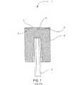
図1は、圧力を測定するための従来のファブリ・ペローセンサー1の構成を示す。双方向光ファイバー2は、光信号をファブリ・ペロー圧力チップ(Fabry-Perot pressure tip)(符号なし)に導く。圧力チップは、ガラス基板4からなる。一つの第1の部分的反射鏡5が、ガラス基板4の上面に形成された窪み空洞3内に取り付けられている。ダイヤフラム7は、ガラス基板4に接着又は溶接され、ダイヤフラム7の内面が第2の鏡6となる。双方の鏡5,6は、ファブリ・ペロー空洞共振器を構成する窪み空洞3の深さの距離だけ離れている。第2の鏡6は、印加圧力に応じて、第1の鏡5に向かって湾曲し、FP空洞の長さを変える。FP空洞の長さが、圧力の一義的な関数となる。 FIG. 1 shows a configuration of a conventional Fabry-
図2は、印加圧力によって変形した一般的なダイヤフラム7の形状を示す。圧力が増加すると、ダイヤフラムの増分偏差は減少する。即ち、ダイヤフラムの偏差は、印加圧力に対して非線形関数である。図3は、異なるダイヤフラム厚を有する同じ圧力センサーの一般的な反応を示す図である。ダイヤフラム厚が減少すると(SiエッチなしからSiエッチ4まで)、最低圧力領域(真空付近)では、感度が非常に増加するが、最高圧力領域(この場合、大気圧付近)で稼働するときには、感度が飽和状態になる。そして、バイアス圧力における絶対圧力センサーの感度の向上が制限される。 FIG. 2 shows the shape of a
上記の感度制限に加えて、ダイヤフラム厚が減少すると、ダイヤフラム内の内部応力が増加し、ダイヤフラム破損が生じる。ダイヤフラム破損の危険性は、システムがバイアス圧(例えば、大気圧)で稼働することで、明らかに増加する。カテーテル先端圧力センシングを有する医療装置において、関心圧力は、大気圧(一般的には、760mmHg)が中心となる。ダイヤフラム厚を減少することで、0mmHga付近での感度は向上するが、760mmHga付近での感度の向上は制限される。 In addition to the sensitivity limitation described above, when the diaphragm thickness is reduced, the internal stress in the diaphragm is increased and the diaphragm is broken. The risk of diaphragm failure is clearly increased when the system is operated at a bias pressure (eg, atmospheric pressure). In medical devices having catheter tip pressure sensing, the pressure of interest is centered on atmospheric pressure (typically 760 mmHg). By reducing the diaphragm thickness, the sensitivity near 0 mmHga is improved, but the improvement in sensitivity near 760 mmHga is limited.
上記の結果の通り、現在の静電容量型の圧力センサーの構成と同様に、現在のファブリ・ペローセンサーを小型化するときの最大の障害は、圧力に対する十分な感度が不足することである。そして、正確性、分解能及び信頼性が不十分なものになるのに対し、他の不必要な寄生効果(例えば、水分漂流(moisture drift)及び熱的効果)が圧力に対して増幅するように思われる。 As described above, like the current configuration of the capacitance type pressure sensor, the biggest obstacle to downsizing the current Fabry-Perot sensor is the lack of sufficient sensitivity to pressure. And so that other unnecessary parasitic effects (eg, moisture drift and thermal effects) are amplified over pressure while accuracy, resolution and reliability are inadequate. Seem.
従って、小型センサーにおける高感度を有するセンサーの構成が必要となっている。 Therefore, a sensor configuration having high sensitivity in a small sensor is required.
バイアス圧力のまわりの感度が最適化された小型光ファイバー圧力センサーの構成について説明する。 A configuration of a small optical fiber pressure sensor in which the sensitivity around the bias pressure is optimized will be described.
一実施形態において、圧力センサーは、基板と、基板に取り付けられたダイヤフラムと、を備えたファブリ・ペロー(FP)センサーである。ダイヤフラムは、中心を有すると共に、第1の材料を有する第1の層と、第2の材料を有する第2の層と、を備える。第2の層は、ドット(dot)を形成する。ドットは、第1の層に取り付けられると共に、ダイヤフラムの中心に配置される。第2の材料は、内部プレストレスを有し、内部プレストレスを解放することで、ダイヤフラムの中心が基板から離れて上反りになる。 In one embodiment, the pressure sensor is a Fabry-Perot (FP) sensor comprising a substrate and a diaphragm attached to the substrate. The diaphragm has a center and a first layer having a first material and a second layer having a second material. The second layer forms dots. The dots are attached to the first layer and placed in the center of the diaphragm. The second material has internal prestress, and releasing the internal prestress causes the center of the diaphragm to warp away from the substrate.
ドットを有する実施形態において、第1の層は、基板に取り付けるために用いられる内面と、内面に対向する外面と、を備え、第2の層は、外面に取り付けられ、第2の材料は、圧縮でプレストレスされる。第2の層の内部圧縮応力が解放して、ダイヤフラムを外側に移動する。その結果として生じるダイヤフラムの形状によって、センサーの圧力感度を上昇させる効果がある。 In embodiments having dots, the first layer comprises an inner surface used for attachment to the substrate and an outer surface opposite the inner surface, the second layer is attached to the outer surface, and the second material is: Prestressed by compression. The internal compressive stress in the second layer is released, moving the diaphragm outward. The resulting diaphragm shape has the effect of increasing the pressure sensitivity of the sensor.
ドットを有し、第2の材料が圧縮でプレストレスされる実施形態において、第1の材料は、シリコンを有する。 In embodiments having dots and the second material being prestressed by compression, the first material comprises silicon.
ドットを有し、第2の材料が圧縮でプレストレスされる実施形態において、第2の材料は、第1の層のシリコン材料に設けられたSiO2を有する。In embodiments having dots and the second material is pre-stressed by compression, the second material comprises SiO2 provided in the silicon material of the first layer.
ドットを有し、第2の材料が圧縮でプレストレスされる実施形態において、第2の材料は、第1の層のシリコン材料に設けられたクロム、アルミニウム、チタン、鉄、金、酸化チタン、酸化タンタル、酸化シリコン、酸化ジルコニウム、酸化アルミニウム及び窒化ケイ素のいずれかを有する。 In an embodiment having dots and the second material is prestressed by compression, the second material is chromium, aluminum, titanium, iron, gold, titanium oxide provided in the first layer of silicon material, One of tantalum oxide, silicon oxide, zirconium oxide, aluminum oxide, and silicon nitride is included.
ドットを有する実施形態において、第1の層は、基板に取り付けるために用いられる内面を備え、第2の層は、内面に取り付けられ、第2の材料は、引張でプレストレスされる。 In embodiments with dots, the first layer comprises an inner surface that is used to attach to the substrate, the second layer is attached to the inner surface, and the second material is prestressed in tension.
ドットを有し、第2の材料が引張でプレストレスされる実施形態において、第1の材料は、シリコンを有する。 In embodiments having dots and the second material being prestressed in tension, the first material comprises silicon.
ドットを有し、第2の材料が引張でプレストレスされる実施形態において、第2の材料は、第1の層のシリコン材料に設けられたクロムを有する。 In embodiments having dots and the second material is pre-stressed by tension, the second material has chromium provided in the silicon material of the first layer.
ドットを有し、第2の材料が引張でプレストレスされる実施形態において、第2の材料は、第1の層のシリコン材料に設けられたクロム、アルミニウム、チタン、鉄、金、酸化チタン、酸化タンタル、酸化シリコン、酸化ジルコニウム、酸化アルミニウム及び窒化ケイ素のいずれかを有する。 In an embodiment having dots and the second material is prestressed by tension, the second material is chromium, aluminum, titanium, iron, gold, titanium oxide provided on the first layer of silicon material, One of tantalum oxide, silicon oxide, zirconium oxide, aluminum oxide, and silicon nitride is included.
他の実施形態において、圧力センサーは、基板と、基板に取り付けられたダイヤフラムと、を備えるファブリ・ペロー(FP)センサーである。ダイヤフラムは、中心を有すると共に、第1の材料を有する第1の層と、第2の材料を有する第2の層と、を備える。第2の層は、リングを形成する。リングは、第1の層に取り付けられると共に、ダイヤフラムの中心に配置される。第2の材料は、内部プレストレスを備え、内部プレストレスを解放することで、ダイヤフラムの中心のまわりの周辺部が基板から離れて上反りになる。 In another embodiment, the pressure sensor is a Fabry-Perot (FP) sensor comprising a substrate and a diaphragm attached to the substrate. The diaphragm has a center and a first layer having a first material and a second layer having a second material. The second layer forms a ring. The ring is attached to the first layer and is located in the center of the diaphragm. The second material has an internal prestress, and by releasing the internal prestress, the peripheral part around the center of the diaphragm is warped away from the substrate.
リングを有する実施形態において、第1の層は、基板に取り付けるために用いられる内面と、内面に対向する外面と、を備え、第2の層は、外面に取り付けられ、第2の材料は、引張でプレストレスされる。 In an embodiment having a ring, the first layer comprises an inner surface used for attachment to the substrate and an outer surface opposite the inner surface, the second layer is attached to the outer surface, and the second material is: Prestressed by tension.
リングを有し、第2の材料が引張でプレストレスされる実施形態において、第1の材料は、シリコンを有する。 In an embodiment having a ring and the second material is prestressed in tension, the first material comprises silicon.
リングを有し、第2の材料が引張でプレストレスされる実施形態において、第2の材料は、第1の層のシリコン材料に設けられたクロムを有する。 In an embodiment having a ring and the second material is pre-stressed by tension, the second material has chromium provided in the silicon material of the first layer.
リングを有し、第2の材料が引張でプレストレスされる実施形態において、第2の材料は、第1の層のシリコン材料に設けられたクロム、アルミニウム、チタン、鉄、金、酸化チタン、酸化タンタル、酸化シリコン、酸化ジルコニウム、酸化アルミニウム及び窒化ケイ素のいずれかを有する。 In an embodiment having a ring and the second material is prestressed by tension, the second material is chromium, aluminum, titanium, iron, gold, titanium oxide provided in the silicon material of the first layer, One of tantalum oxide, silicon oxide, zirconium oxide, aluminum oxide, and silicon nitride is included.
リングを有する実施形態において、第1の層は、基板に取り付けるために用いられる内面を備え、第2の層は、内面に取り付けられ、第2の材料は、圧縮でプレストレスされる。 In embodiments having a ring, the first layer comprises an inner surface used for attachment to the substrate, the second layer is attached to the inner surface, and the second material is prestressed by compression.
リングを有し、第2の材料が引張でプレストレスされる実施形態において、第1の材料は、シリコンを有する。 In an embodiment having a ring and the second material is prestressed in tension, the first material comprises silicon.
リングを有し、第2の材料が引張でプレストレスされる実施形態において、第2の材料は、第1の層のシリコン材料に設けられたSiO2を有する。In an embodiment having a ring and the second material is prestressed by tension, the second material comprises SiO2 provided in the silicon material of the first layer.
リングを有し、第2の材料が引張でプレストレスされる実施形態において、第2の材料は、第1の層のシリコン材料に設けられたクロム、アルミニウム、チタン、鉄、金、酸化チタン、酸化タンタル、酸化シリコン、酸化ジルコニウム、酸化アルミニウム及び窒化ケイ素のいずれかを有する。 In an embodiment having a ring and the second material is prestressed by tension, the second material is chromium, aluminum, titanium, iron, gold, titanium oxide provided in the silicon material of the first layer, One of tantalum oxide, silicon oxide, zirconium oxide, aluminum oxide, and silicon nitride is included.
ダイヤフラム上に取り付けられ、成長され、又は、その他で設けられた内部プレストレス材料を加えることで、小型のファブリ・ペロー又は静電容量型の圧力センサーの感度が増加し、さらに、このような内部プレストレス材料の解放下で、バイアス圧力での感度が増加するように、ダイヤフラムの形状変化を生じさせる。 Adding internal prestressed material mounted, grown or otherwise on the diaphragm increases the sensitivity of a small Fabry-Perot or capacitive pressure sensor, and such internal Under the release of the prestress material, a change in the shape of the diaphragm is caused so that the sensitivity at the bias pressure increases.
実施形態に関する以下の説明において、添付図面を参照して、本発明を説明する。なお、開示された本発明の範囲から逸脱することなく、他の実施形態でもよいことは理解できる。 In the following description of the embodiments, the present invention will be described with reference to the accompanying drawings. It should be understood that other embodiments may be used without departing from the scope of the disclosed invention.
図1に示す圧力センサーに対して、印加圧力は、ダイヤフラム7の変形を測定することで得られる。このようなセンサーの感度は、印加圧力に対するダイヤフラムの変形によって得られる。ダイヤフラムが大きく変形するほど、感度は良くなる。 For the pressure sensor shown in FIG. 1, the applied pressure is obtained by measuring the deformation of the
バイアス圧力範囲(真空からオフセットされた圧力範囲)で稼働する絶対圧力センサーの感度は、ダイヤフラムを薄くすることで向上すると言われている。しかし、図3では、所定のダイヤフラム厚さに対して、ダイヤフラムを薄くしても、感度が向上しないことを示している。ダイヤフラムが薄くなると、低圧での感度は増加するが、例えば、760mmHgのような高圧では、それ以上、感度は向上しない。所定のバイアス圧力範囲で稼働する所定の圧力センサーダイヤフラムの直径に対しては、超えることができない最高感度がある。 It is said that the sensitivity of an absolute pressure sensor operating in the bias pressure range (pressure range offset from vacuum) is improved by making the diaphragm thinner. However, FIG. 3 shows that the sensitivity is not improved even if the diaphragm is thinned with respect to a predetermined diaphragm thickness. As the diaphragm becomes thinner, the sensitivity at low pressure increases. However, at a high pressure such as 760 mmHg, the sensitivity does not increase further. There is a maximum sensitivity that cannot be exceeded for a given pressure sensor diaphragm diameter operating in a given bias pressure range.
このような圧力センサーの感度を増加する方法の一つとして、バイアス圧力が存在しない箇所にダイヤフラムを再配置することがある。この目的を達成する方法の一つとして、バイアス圧力での差圧がなくなるように、バイアス圧力(カテーテル先端装置に対する大気圧(atmospheric pressure for catheter tip applications))と同じ圧力で、センサーの内部空洞をガスで充填することがある。しかし、真空にする代わりに、ガスで内部空洞を充填すると、センサーは温度に対して非常に敏感になる。例えば、大気圧では、圧力センサーの内部空洞でのガス圧力は、20度から37度に温度上昇すると、44mmHg増加する。 One way to increase the sensitivity of such a pressure sensor is to reposition the diaphragm where there is no bias pressure. One way to achieve this goal is to close the sensor's internal cavity at the same pressure as the bias pressure (atmospheric pressure for catheter tip applications) so that there is no differential pressure at the bias pressure. May be filled with gas. However, instead of applying a vacuum, filling the internal cavity with gas makes the sensor very sensitive to temperature. For example, at atmospheric pressure, the gas pressure in the internal cavity of the pressure sensor increases by 44 mmHg as the temperature increases from 20 degrees to 37 degrees.
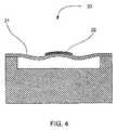
図4に示す実施形態では、ダイヤフラムの外面に引張応力を生じさせることで、ダイヤフラムが上方の最適位置に移動するように、ダイヤフラムが元の位置の近くに再配置されるように構成されている。展伸材の薄層22(内部圧縮応力を解放するこのような層を有することで提供される)をダイヤフラム21の外面の中心に配置することで、この目的を達成できる。 In the embodiment shown in FIG. 4, the diaphragm is rearranged close to the original position so that the diaphragm moves to the upper optimal position by generating a tensile stress on the outer surface of the diaphragm. . By placing a
図5〜図8は、このような高圧力感度を有する圧力センサーを製作する方法を示す図である。図5に示す通り、ファブリ・ペロー(Fabry-Perot)圧力センサーのダイヤフラムは、シリコン・オン・インスレーター(SOI)を用いて製作できる。SOIは、ハンドル33からなり、シリコンの厚い部分である。センサーが完成すると、ハンドル33は、通常、解放(released)、即ち、取り除かれる(removed)。シリコン具31は、ダイヤフラムを構成するSOIの一部である。これは、二酸化ケイ素(SiO2)の層32によってハンドルから分離される。二酸化ケイ素にわたるシリコンを選択的にエッチングするための化学薬品があるので、SiO2層32によって簡単にダイヤフラムをハンドルから取り外すことができる。5-8 is a figure which shows the method of manufacturing the pressure sensor which has such a high pressure sensitivity. As shown in FIG. 5, a Fabry-Perot pressure sensor diaphragm can be fabricated using a silicon-on-insulator (SOI). The SOI consists of a
SOI基板の製作工程は、かなり高い温度でSiO2層32を熱成長させる。SiO2層32が成長する温度、及びSiO2とシリコン具31との間の熱膨張係数(室温で、それぞれ0.5×10⁻⁶及び2.7×10⁻⁶)を考慮すると、室温で、SiO2層32は大きな圧縮応力を受けることが明らかである。同様に、シリコン具31は、反対の応力(引張応力)を受ける。In the manufacturing process of the SOI substrate, the SiO2 layer 32 is thermally grown at a considerably high temperature. Considering the temperature at which the SiO2 layer 32 grows and the thermal expansion coefficient between the SiO2 and the silicon tool 31 (at room temperature, 0.5 × 10⁻⁶ and 2.7 × 10⁻⁶ , respectively), at room temperature It is clear that the SiO2 layer 32 is subjected to a large compressive stress. Similarly, the
図6に示す通り、シリコン具41及びSiO2層42は、ハンドルから取り外されると、残りの層がたわむことがわかる。この挙動はバイメタルと同様であって、複合材料は、層の応力を緩和するために湾曲する。SiO2層42は圧縮応力下で伸長しようとする一方、シリコン具41は引張応力下で収縮しようとする。As shown in FIG. 6, when the
ファブリ・ペロー圧力センサー(図7)を製作するためにSOIを使用するとき、SOI全体は、陽極接合でガラス基板51に接合され、先ず、ファブリ・ペロー空洞52が、表面にエッチングされる。SOIがガラス基板に接合された後、当業者に良く知られる研磨及びエッチング工程によって、ハンドルが取り外される。センサーには、シリコン具層53及びSiO2層54からなるダイヤフラムが残される。図6に示すダイヤフラムのバイメタル作業の結果、ダイヤフラムが上方へ移動することがわかるが、これは外部からのバイアス圧力を考慮していない。たわんだダイヤフラムの外面における応力は、純粋な引張応力ではない。ダイヤフラムの中央部57は圧縮されており、端部55は引っ張られている。SiO2層54及びシリコン具層53に対する内部応力の緩和によって、中央部57は外側へ移動するが、端部55は内側へ移動する。これら二つの力は、大部分で互いに釣り合っている。最終的に、ダイヤフラムは元の位置へ戻らない。When using SOI to fabricate a Fabry-Perot pressure sensor (FIG. 7), the entire SOI is bonded to the
ダイヤフラムを内側へ移動するSiO2層54の端部55を取り除き、ダイヤフラムを外側へ引っ張る中央部57のみを残すことで、上記の釣り合いの影響を減少できる。図8は、最適位置へ戻したダイヤフラムを有する同一の圧力センサーを示す図である。中央のSiO2ドット部(dot portion)61は、シリコンダイヤフラム62の外面にわたって無傷で残されるのに対し、端部は、当業者に良く知られる選択的エッチング(preferential etching)によって取り除かれる。By removing the
様々なパラメーターを適用することで、最適な設計がなされることがわかる。図9及び図10は、1)同一のダイヤフラム直径で、2)異なるダイヤフラム厚(図9のセンサーは、より厚い方のダイヤフラムである)で、及び3)SiO2ドット厚が様々な、二つの圧力センサーの感度を示す図であり、It can be seen that an optimum design can be made by applying various parameters. FIGS. 9 and 10 show two cases of 1) the same diaphragm diameter, 2) different diaphragm thicknesses (the sensor of FIG. 9 is the thicker diaphragm), and 3) various SiO2 dot thicknesses. It is a diagram showing the sensitivity of the pressure sensor,
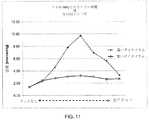
図11は、760mmHgにおける図9及び図10の反応曲線の傾斜を示す。ドットがないとき、760mmHgにおける圧力センサー(薄いダイヤフラムと厚いダイヤフラムの双方)の感度は、双方とも、1.36nm/mmHgと測定される。従って、ダイヤフラムを薄くしても感度を向上することはできない。一方、薄いダイヤフラム及び最適SiO2ドット厚を有するセンサーにおける最高感度は、9.7nm/mmHgまで上昇するのに対し、厚いダイヤフラムを有するセンサーでは3.2nm/mmHgとなる。これは、ドットのない1.36nm/mmHgの感度より優れている。FIG. 11 shows the slope of the response curves of FIGS. 9 and 10 at 760 mmHg. In the absence of dots, the sensitivity of the pressure sensor at 760 mmHg (both thin and thick diaphragms) is both measured at 1.36 nm / mmHg. Therefore, the sensitivity cannot be improved even if the diaphragm is thinned. On the other hand, the maximum sensitivity for sensors with thin diaphragms and optimum SiO2 dot thickness rises to 9.7 nm / mmHg, whereas for sensors with thick diaphragms it is 3.2 nm / mmHg. This is superior to the sensitivity of 1.36 nm / mmHg without dots.
最高感度は、圧力範囲の制限領域で生じる。SiO2ドットは、SiO2ドットのないセンサーのセンサー反応曲線をより高圧側にスライドする作用を有している。即ち、センサー反応曲線が、より大きな圧力側にバイアスされる。SiO2ドットがないとき、センサー反応は0mmHgで変曲点を有しており、ダイヤフラムは平坦である。負圧(圧力が内部空洞の内側でより高い状態)におけるセンサー反応は対称となる。図9及び図10では、より高圧側にシフトした全体の反応曲線であって、SiO2ドットの厚さが増加すると、変曲点がより高圧側に移動する。このようなプレストレス・ドット(pre-stress dot)の存在によって、最高感度を実際のバイアス圧力(actual bias pressure)に相当する点にもたらす圧力センサーに対して、バイアス(bias)を生じさせる。Maximum sensitivity occurs in the restricted region of the pressure range. The SiO2 dots have the effect of sliding the sensor response curve of the sensor without the SiO2 dots to the higher pressure side. That is, the sensor response curve is biased to a larger pressure side. In the absence of SiO2 dots, the sensor response has an inflection point at 0 mmHg and the diaphragm is flat. The sensor response at negative pressure (where the pressure is higher inside the internal cavity) is symmetric. In FIGS. 9 and 10, the overall reaction curve is shifted to the higher pressure side, and the inflection point moves to the higher pressure side as the thickness of the SiO2 dots increases. The presence of such pre-stress dots creates a bias for the pressure sensor that provides the highest sensitivity at a point corresponding to the actual bias pressure.
ダイヤフラムをバイアスすることで、圧力センサーの感度を向上できることがわかる。圧縮でプレストレスされたドットをダイヤフラムの外面の中央に付加することで、ダイヤフラムがバイアスされる。このような内部圧縮応力を解放することで、ダイヤフラムは外側に湾曲して感度が向上する。同様に、引張でプレストレスされたドットをダイヤフラムの外面の中央に付加することで、ダイヤフラムをバイアスできる。 It can be seen that the sensitivity of the pressure sensor can be improved by biasing the diaphragm. The diaphragm is biased by adding a dot prestressed by compression to the center of the outer surface of the diaphragm. By releasing such internal compressive stress, the diaphragm is curved outward and the sensitivity is improved. Similarly, the diaphragm can be biased by adding a tension prestressed dot to the center of the outer surface of the diaphragm.
図12は、FPセンサー70を示す図であり、ダイヤフラムが上方の最適位置に移動するように、ダイヤフラムの内面に圧縮応力を生じさせることで、ダイヤフラムはその平坦位置付近に再配置される。材料の薄層72が、内部引張応力を生じると共に、ダイヤフラム71の内面の中心に配置されることで、この目的が達成される。このような内部引張応力を生じさせるために付着又は成長される関心材料として、例えば、クロム、アルミニウム、チタン、鉄、金、酸化チタン、酸化タンタル、酸化シリコン、酸化ジルコニウム、酸化アルミニウム及び窒化ケイ素がある。 FIG. 12 is a diagram showing the
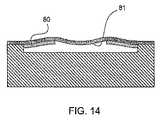
同様の構成として、ダイヤフラムの周辺端部55に付着又は成長した、リング形状の材料のプレストレス層を有するものも含む。図13に示す通り、内部引張応力を有する層75がダイヤフラムの外面76の周辺部に付着又は成長することで、同様の結果が生じる一方で、図14の通り、内部圧縮応力を有する層80がダイヤフラムの内面81の周辺部に付着又は成長することで、同様の結果が生じる。 Similar configurations include those having a prestress layer of ring-shaped material attached or grown on the
ウエハーを製作する間にシリコン・オン・インスレーター(SOI)ウエハーの層のSiO2内に発生する圧縮応力を用いて、本発明の実施形態が実証される。しかし、付着、成長又は他の工程の後に、他の付着又は成長された材料の薄層に内部応力を生じさせることによっても、同じ目的を達成できることがわかる。例えば、クロム、アルミニウム、チタン、鉄、金、酸化チタン、酸化タンタル、酸化シリコン、酸化ジルコニウム、酸化アルミニウム及び窒化ケイ素が、内部応力と共に付着される材料の一つである。Embodiments of the present invention are demonstrated using compressive stresses that occur in the SiO2 of a layer of a silicon-on-insulator (SOI) wafer during wafer fabrication. However, it can be seen that the same objective can be achieved by applying internal stress to a thin layer of other deposited or grown material after deposition, growth or other steps. For example, chromium, aluminum, titanium, iron, gold, titanium oxide, tantalum oxide, silicon oxide, zirconium oxide, aluminum oxide, and silicon nitride are one of the materials that are deposited with internal stress.
特定の実施形態に基づいて上記の通り本発明を説明したが、本発明の思想の範囲から逸脱することなく実施できる。 Although the invention has been described above based on specific embodiments, it can be practiced without departing from the scope of the spirit of the invention.
Claims (18)
Translated fromJapanese前記基板に取り付けられたダイヤフラムと、を備え、
前記ダイヤフラムは、中心を有すると共に、
第1の材料を有する第1の層と、
第2の材料を有する第2の層と、を備え、前記第2の層は、ドットを形成し、前記ドットは、前記第1の層に取り付けられると共に、前記ダイヤフラムの中心に配置され、前記第2の材料は、内部プレストレスを備え、前記内部プレストレスを解放することで、前記ダイヤフラムの中心が前記基板から離れて上反りになる
ことを特徴とするファブリ・ペロー(FP)センサー。A substrate,
A diaphragm attached to the substrate,
The diaphragm has a center and
A first layer having a first material;
A second layer comprising a second material, wherein the second layer forms a dot, the dot is attached to the first layer and disposed at the center of the diaphragm, The Fabry-Perot (FP) sensor, wherein the second material includes an internal prestress, and the center of the diaphragm is warped away from the substrate by releasing the internal prestress.
前記基板に取り付けられたダイヤフラムと、を備え、
前記ダイヤフラムは、中心を有すると共に、
第1の材料を有する第1の層と、
第2の材料を有する第2の層と、を備え、前記第2の層は、リングを形成し、前記リングは、前記第1の層に取り付けられると共に、前記ダイヤフラムの中心に配置され、前記第2の材料は、内部プレストレスを備え、前記内部プレストレスを解放することで、前記ダイヤフラムの中心のまわりの周辺部が前記基板から離れて上反りになる
ことを特徴とするファブリ・ペロー(FP)センサー。A substrate,
A diaphragm attached to the substrate,
The diaphragm has a center and
A first layer having a first material;
A second layer comprising a second material, the second layer forming a ring, the ring being attached to the first layer and disposed in the center of the diaphragm, The second material includes an internal prestress, and the peripheral part around the center of the diaphragm is warped away from the substrate by releasing the internal prestress. FP) sensor.
Applications Claiming Priority (3)
| Application Number | Priority Date | Filing Date | Title |
|---|---|---|---|
| US201161450959P | 2011-03-09 | 2011-03-09 | |
| US61/450,959 | 2011-03-09 | ||
| PCT/CA2012/000211WO2012119237A1 (en) | 2011-03-09 | 2012-03-09 | A miniature high sensitivity pressure sensor |
Publications (2)
| Publication Number | Publication Date |
|---|---|
| JP2014507666Atrue JP2014507666A (en) | 2014-03-27 |
| JP5894197B2 JP5894197B2 (en) | 2016-03-23 |
Family
ID=46794292
Family Applications (1)
| Application Number | Title | Priority Date | Filing Date |
|---|---|---|---|
| JP2013556942AActiveJP5894197B2 (en) | 2011-03-09 | 2012-03-09 | Compact high-sensitivity pressure sensor |
Country Status (6)
| Country | Link |
|---|---|
| US (1) | US8752435B2 (en) |
| EP (1) | EP2638375B1 (en) |
| JP (1) | JP5894197B2 (en) |
| CN (1) | CN103534568B (en) |
| CA (1) | CA2819564C (en) |
| WO (1) | WO2012119237A1 (en) |
Cited By (2)
| Publication number | Priority date | Publication date | Assignee | Title |
|---|---|---|---|---|
| JP2016508051A (en)* | 2012-12-28 | 2016-03-17 | ヴォルカノ コーポレイションVolcano Corporation | Intravascular device having stored information and / or wireless communication function, and related device, system and method |
| US11454558B2 (en) | 2017-12-05 | 2022-09-27 | Beijing Bywave Sensing Science & Technology Development Co., Ltd. | Fabry-Perot sensor and method for manufacturing same |
Families Citing this family (63)
| Publication number | Priority date | Publication date | Assignee | Title |
|---|---|---|---|---|
| CN103328033B (en) | 2010-11-09 | 2016-05-18 | 奥普森斯公司 | There is the seal wire of internal pressure sensor |
| US10463259B2 (en) | 2011-10-28 | 2019-11-05 | Three Rivers Cardiovascular Systems Inc. | System and apparatus comprising a multi-sensor catheter for right heart and pulmonary artery catheterization |
| US20140243688A1 (en) | 2011-10-28 | 2014-08-28 | Three Rivers Cardiovascular Systems Inc. | Fluid temperature and flow sensor apparatus and system for cardiovascular and other medical applications |
| DE102012207053A1 (en) | 2012-04-27 | 2013-10-31 | Abiomed Europe Gmbh | INTRAVASAL ROTATION BLOOD PUMP |
| WO2013177577A2 (en) | 2012-05-25 | 2013-11-28 | Eberle Michael J | Optical fiber pressure sensor |
| EP2887863B1 (en) | 2012-08-27 | 2019-11-27 | Boston Scientific Scimed, Inc. | Pressure-sensing medical device system |
| DE102012111533A1 (en)* | 2012-11-28 | 2014-05-28 | Endress + Hauser Gmbh + Co. Kg | Pressure measuring cell |
| EP2934309B1 (en) | 2012-12-21 | 2022-02-09 | Philips Image Guided Therapy Corporation | Pressure-sensing intravascular device |
| JP2016501674A (en) | 2012-12-28 | 2016-01-21 | ヴォルカノ コーポレイションVolcano Corporation | Intravascular device, system, and method with information stored in the intravascular device and / or wireless communication capability with associated devices |
| CN105209102B (en) | 2013-03-15 | 2018-10-02 | 波士顿科学国际有限公司 | Pressure-sensing seal wire |
| CN105682544B (en) | 2013-05-22 | 2019-09-24 | 波士顿科学国际有限公司 | Pressure detecting godet system including optical connector optical cable |
| CN103344381B (en)* | 2013-06-08 | 2016-03-30 | 天津大学 | Wide region vacuum optical fiber sensor with multiple stage rank and preparation method thereof |
| WO2015013646A1 (en) | 2013-07-26 | 2015-01-29 | Boston Scientific Scimed, Inc. | Ffr sensor head design that minimizes stress induced pressure offsets |
| US10835182B2 (en) | 2013-08-14 | 2020-11-17 | Boston Scientific Scimed, Inc. | Medical device systems including an optical fiber with a tapered core |
| WO2015051003A1 (en) | 2013-10-04 | 2015-04-09 | Vascular Imaging Corporation | Imaging techniques using an imaging guidewire |
| WO2015057518A1 (en) | 2013-10-14 | 2015-04-23 | Boston Scientific Scimed, Inc. | Pressure sensing guidewire and methods for calculating fractional flow reserve |
| CN104614119B (en)* | 2013-11-05 | 2017-11-28 | 中芯国际集成电路制造(上海)有限公司 | Pressure sensor and forming method thereof |
| US9877660B2 (en) | 2013-11-14 | 2018-01-30 | Medtronic Vascular Galway | Systems and methods for determining fractional flow reserve without adenosine or other pharmalogical agent |
| US10130269B2 (en) | 2013-11-14 | 2018-11-20 | Medtronic Vascular, Inc | Dual lumen catheter for providing a vascular pressure measurement |
| US10537255B2 (en) | 2013-11-21 | 2020-01-21 | Phyzhon Health Inc. | Optical fiber pressure sensor |
| US9913585B2 (en) | 2014-01-15 | 2018-03-13 | Medtronic Vascular, Inc. | Catheter for providing vascular pressure measurements |
| JP6311341B2 (en)* | 2014-02-14 | 2018-04-18 | オムロン株式会社 | Capacitance type pressure sensor and input device |
| US10932679B2 (en) | 2014-03-18 | 2021-03-02 | Boston Scientific Scimed, Inc. | Pressure sensing guidewires and methods of use |
| EP3132296B1 (en) | 2014-04-17 | 2023-01-04 | Boston Scientific Scimed, Inc. | Self-cleaning optical connector |
| WO2015187385A1 (en) | 2014-06-04 | 2015-12-10 | Boston Scientific Scimed, Inc. | Pressure sensing guidewire systems with reduced pressure offsets |
| US10973418B2 (en) | 2014-06-16 | 2021-04-13 | Medtronic Vascular, Inc. | Microcatheter sensor design for minimizing profile and impact of wire strain on sensor |
| US10201284B2 (en) | 2014-06-16 | 2019-02-12 | Medtronic Vascular Inc. | Pressure measuring catheter having reduced error from bending stresses |
| US11330989B2 (en) | 2014-06-16 | 2022-05-17 | Medtronic Vascular, Inc. | Microcatheter sensor design for mounting sensor to minimize induced strain |
| CA2954959C (en) | 2014-07-13 | 2018-03-20 | Three Rivers Cardiovascular Systems Inc. | System and apparatus comprising a multisensor guidewire for use in interventional cardiology |
| WO2016019207A1 (en) | 2014-08-01 | 2016-02-04 | Boston Scientific Scimed, Inc. | Pressure sensing guidewires |
| US10080872B2 (en) | 2014-11-04 | 2018-09-25 | Abbott Cardiovascular Systems Inc. | System and method for FFR guidewire recovery |
| US10258240B1 (en) | 2014-11-24 | 2019-04-16 | Vascular Imaging Corporation | Optical fiber pressure sensor |
| CN107405089B (en) | 2014-12-05 | 2020-09-04 | 波士顿科学国际有限公司 | Pressure sensing guide wire |
| US10194812B2 (en) | 2014-12-12 | 2019-02-05 | Medtronic Vascular, Inc. | System and method of integrating a fractional flow reserve device with a conventional hemodynamic monitoring system |
| DE102015000773B4 (en) | 2015-01-26 | 2021-09-16 | Karl Storz Se & Co. Kg | Endoscope and method of making an endoscope |
| PT3353517T (en)* | 2015-09-21 | 2020-05-20 | Opsens Solutions Inc | Optical pressure sensor with reduced mechanical stresses |
| US11633113B2 (en) | 2015-10-09 | 2023-04-25 | Phyzhon Health Inc. | Optical sensor assemblies and methods |
| CN105725973A (en)* | 2016-02-02 | 2016-07-06 | 杨松 | Shaping pillow capable of collecting human body physiological data and system |
| EP3419514B1 (en) | 2016-02-23 | 2023-08-23 | Boston Scientific Scimed, Inc. | Pressure sensing guidewire systems including an optical connector cable |
| US10342906B2 (en) | 2016-06-06 | 2019-07-09 | Abiomed, Inc. | Blood pump assembly having a sensor and a sensor shield |
| US11272850B2 (en) | 2016-08-09 | 2022-03-15 | Medtronic Vascular, Inc. | Catheter and method for calculating fractional flow reserve |
| US11272847B2 (en) | 2016-10-14 | 2022-03-15 | Hemocath Ltd. | System and apparatus comprising a multi-sensor catheter for right heart and pulmonary artery catheterization |
| US11330994B2 (en) | 2017-03-08 | 2022-05-17 | Medtronic Vascular, Inc. | Reduced profile FFR catheter |
| US10646122B2 (en) | 2017-04-28 | 2020-05-12 | Medtronic Vascular, Inc. | FFR catheter with covered distal pressure sensor and method of manufacture |
| CN116327157B (en) | 2017-08-03 | 2025-09-30 | 波士顿科学国际有限公司 | Methods for assessing fractional flow reserve |
| US11219741B2 (en) | 2017-08-09 | 2022-01-11 | Medtronic Vascular, Inc. | Collapsible catheter and method for calculating fractional flow reserve |
| US11235124B2 (en) | 2017-08-09 | 2022-02-01 | Medtronic Vascular, Inc. | Collapsible catheter and method for calculating fractional flow reserve |
| US11311196B2 (en) | 2018-02-23 | 2022-04-26 | Boston Scientific Scimed, Inc. | Methods for assessing a vessel with sequential physiological measurements |
| EP3768156B1 (en) | 2018-03-23 | 2023-09-20 | Boston Scientific Scimed, Inc. | Medical device with pressure sensor |
| WO2019195721A1 (en) | 2018-04-06 | 2019-10-10 | Boston Scientific Scimed, Inc. | Medical device with pressure sensor |
| CN119564167A (en) | 2018-04-18 | 2025-03-07 | 波士顿科学国际有限公司 | System for vascular assessment using continuous physiological measurements |
| US11185244B2 (en) | 2018-08-13 | 2021-11-30 | Medtronic Vascular, Inc. | FFR catheter with suspended pressure sensor |
| CN109238437A (en)* | 2018-08-28 | 2019-01-18 | 电子科技大学 | A kind of Fabry-perot optical fiber sonic probe based on silicon nitride MEMS film |
| CN109259752A (en)* | 2018-09-25 | 2019-01-25 | 山东大学 | FFR sensor structure based on fiber F-P cavity principle |
| CN109770854B (en)* | 2019-02-02 | 2021-10-01 | 东北大学秦皇岛分校 | Human body sign information monitoring system based on optical fiber sensing |
| WO2021062527A1 (en) | 2019-09-30 | 2021-04-08 | Hemocath Ltd. | Multi-sensor catheter for right heart and pulmonary artery catheterization |
| US20210214211A1 (en)* | 2020-01-15 | 2021-07-15 | Stmicroelectronics Pte Ltd | Mems thin membrane with stress structure |
| CN111473896A (en)* | 2020-05-26 | 2020-07-31 | 中山大学 | An optical fiber pressure sensor based on soft silicon diaphragm and its detection method |
| US12087000B2 (en) | 2021-03-05 | 2024-09-10 | Boston Scientific Scimed, Inc. | Systems and methods for vascular image co-registration |
| EP4329676A1 (en) | 2021-04-29 | 2024-03-06 | Edwards Lifesciences Corporation | Prosthetic heart valve delivery assemblies with multiple location pressure sensing |
| US11872403B2 (en) | 2021-08-06 | 2024-01-16 | Solo Pace Inc. | Systems, methods, and apparatus for external cardiac pacing |
| EP4380678A1 (en) | 2021-08-06 | 2024-06-12 | Solo Pace Inc. | Systems, methods, and apparatus for external cardiac pacing |
| WO2025029856A1 (en) | 2023-08-01 | 2025-02-06 | Solo Pace Inc. | Systems, methods, and apparatus for ambulatory cardiac pacing |
Citations (5)
| Publication number | Priority date | Publication date | Assignee | Title |
|---|---|---|---|---|
| JPS5737235A (en)* | 1980-08-19 | 1982-03-01 | Omron Tateisi Electronics Co | Semiconductor pressure-sensitive device |
| JP2000340805A (en)* | 1999-04-19 | 2000-12-08 | Motorola Inc | Electronic part and manufacture |
| JP2005156164A (en)* | 2003-11-20 | 2005-06-16 | Matsushita Electric Works Ltd | Pressure sensor, and manufacturing method for pressure sensor |
| JP2006319945A (en)* | 2005-04-12 | 2006-11-24 | Osaka Industrial Promotion Organization | Diaphragm type sensor element and manufacturing method thereof |
| JP2008524606A (en)* | 2004-12-22 | 2008-07-10 | オプセンス インコーポレイテッド | Optical fiber pressure sensor for catheter |
Family Cites Families (12)
| Publication number | Priority date | Publication date | Assignee | Title |
|---|---|---|---|---|
| DE4018998A1 (en) | 1990-06-13 | 1992-01-02 | Dynisco Geraete Gmbh | FIBER OPTICAL PRESSURE SENSOR |
| US5868678A (en)* | 1993-06-30 | 1999-02-09 | Medex, Inc. | Two-part medical pressure transducer with diaphragm stand-offs |
| US5808210A (en)* | 1996-12-31 | 1998-09-15 | Honeywell Inc. | Thin film resonant microbeam absolute pressure sensor |
| DE69922727T2 (en) | 1998-03-31 | 2005-12-15 | Hitachi, Ltd. | Capacitive pressure transducer |
| US7235914B2 (en)* | 2000-10-25 | 2007-06-26 | Washington State University Research Foundation | Piezoelectric micro-transducers, methods of use and manufacturing methods for same |
| WO2006092052A1 (en)* | 2005-03-02 | 2006-09-08 | Fiso Technologies Inc. | Fabry-perot optical sensor and method of manufacturing the same |
| US6984141B1 (en) | 2005-03-02 | 2006-01-10 | Casco Products Corporation | Power socket device with enabling switch |
| WO2007019676A1 (en) | 2005-08-12 | 2007-02-22 | Fiso Technologies Inc. | Single piece fabry-perot optical sensor and method of manufacturing the same |
| WO2007126491A2 (en)* | 2006-03-31 | 2007-11-08 | Davidson Instruments, Inc. | Differential pressure transducer configurations including displacement sensor |
| CN101164675A (en)* | 2006-10-20 | 2008-04-23 | 霍尼韦尔国际公司 | Polymer self-assembling multi-layer film for ion selection: design, preparation and use in sensor |
| US7707891B2 (en) | 2008-06-27 | 2010-05-04 | Inficon Gmbh | Optical interferometric pressure sensor |
| CN101982864B (en)* | 2010-09-30 | 2015-03-04 | 深圳市金亿帝科技有限公司 | Movable electrode of variable capacitor, pressure sensor and blood pressure measuring equipment |
- 2012
- 2012-03-08USUS13/415,514patent/US8752435B2/enactiveActive
- 2012-03-09CACA2819564Apatent/CA2819564C/enactiveActive
- 2012-03-09EPEP12755222.2Apatent/EP2638375B1/enactiveActive
- 2012-03-09JPJP2013556942Apatent/JP5894197B2/enactiveActive
- 2012-03-09WOPCT/CA2012/000211patent/WO2012119237A1/enactiveApplication Filing
- 2012-03-09CNCN201280022543.2Apatent/CN103534568B/enactiveActive
Patent Citations (5)
| Publication number | Priority date | Publication date | Assignee | Title |
|---|---|---|---|---|
| JPS5737235A (en)* | 1980-08-19 | 1982-03-01 | Omron Tateisi Electronics Co | Semiconductor pressure-sensitive device |
| JP2000340805A (en)* | 1999-04-19 | 2000-12-08 | Motorola Inc | Electronic part and manufacture |
| JP2005156164A (en)* | 2003-11-20 | 2005-06-16 | Matsushita Electric Works Ltd | Pressure sensor, and manufacturing method for pressure sensor |
| JP2008524606A (en)* | 2004-12-22 | 2008-07-10 | オプセンス インコーポレイテッド | Optical fiber pressure sensor for catheter |
| JP2006319945A (en)* | 2005-04-12 | 2006-11-24 | Osaka Industrial Promotion Organization | Diaphragm type sensor element and manufacturing method thereof |
Cited By (2)
| Publication number | Priority date | Publication date | Assignee | Title |
|---|---|---|---|---|
| JP2016508051A (en)* | 2012-12-28 | 2016-03-17 | ヴォルカノ コーポレイションVolcano Corporation | Intravascular device having stored information and / or wireless communication function, and related device, system and method |
| US11454558B2 (en) | 2017-12-05 | 2022-09-27 | Beijing Bywave Sensing Science & Technology Development Co., Ltd. | Fabry-Perot sensor and method for manufacturing same |
Also Published As
| Publication number | Publication date |
|---|---|
| JP5894197B2 (en) | 2016-03-23 |
| WO2012119237A1 (en) | 2012-09-13 |
| EP2638375B1 (en) | 2019-01-02 |
| CA2819564A1 (en) | 2012-09-13 |
| CN103534568B (en) | 2015-11-25 |
| CA2819564C (en) | 2017-01-24 |
| US20120227505A1 (en) | 2012-09-13 |
| EP2638375A4 (en) | 2014-10-15 |
| US8752435B2 (en) | 2014-06-17 |
| EP2638375A1 (en) | 2013-09-18 |
| CN103534568A (en) | 2014-01-22 |
Similar Documents
| Publication | Publication Date | Title |
|---|---|---|
| JP5894197B2 (en) | Compact high-sensitivity pressure sensor | |
| US7689071B2 (en) | Fiber optic pressure sensor for catheter use | |
| US6546804B2 (en) | Method of making a pressure sensor comprising a resonant beam structure | |
| CN102576149B (en) | For the actuator of mobile micro mechanical organ | |
| EP2339357B1 (en) | Method for fabricating a sensor | |
| JP4871513B2 (en) | Micromechanical device with thinly formed cantilever structure and related method | |
| JP6053357B2 (en) | Pressure measuring device with optimized sensitivity | |
| US7207227B2 (en) | Pressure sensor | |
| US20100320548A1 (en) | Silicon-Rich Nitride Etch Stop Layer for Vapor HF Etching in MEMS Device Fabrication | |
| US9010200B2 (en) | Device for measuring forces and method of making the same | |
| WO2016119417A1 (en) | Z-axis structure of accelerometer and method for manufacturing same | |
| JP2009276176A (en) | Mems and mems production method | |
| CN113891224A (en) | A kind of MEMS structure and its manufacturing method | |
| JPH116779A (en) | Pressure sensor |
Legal Events
| Date | Code | Title | Description |
|---|---|---|---|
| A621 | Written request for application examination | Free format text:JAPANESE INTERMEDIATE CODE: A621 Effective date:20140522 | |
| A977 | Report on retrieval | Free format text:JAPANESE INTERMEDIATE CODE: A971007 Effective date:20150218 | |
| A131 | Notification of reasons for refusal | Free format text:JAPANESE INTERMEDIATE CODE: A131 Effective date:20150225 | |
| A521 | Request for written amendment filed | Free format text:JAPANESE INTERMEDIATE CODE: A523 Effective date:20150417 | |
| A131 | Notification of reasons for refusal | Free format text:JAPANESE INTERMEDIATE CODE: A131 Effective date:20150603 | |
| A521 | Request for written amendment filed | Free format text:JAPANESE INTERMEDIATE CODE: A523 Effective date:20150604 | |
| A131 | Notification of reasons for refusal | Free format text:JAPANESE INTERMEDIATE CODE: A131 Effective date:20151104 | |
| A521 | Request for written amendment filed | Free format text:JAPANESE INTERMEDIATE CODE: A523 Effective date:20151222 | |
| TRDD | Decision of grant or rejection written | ||
| A01 | Written decision to grant a patent or to grant a registration (utility model) | Free format text:JAPANESE INTERMEDIATE CODE: A01 Effective date:20160210 | |
| A61 | First payment of annual fees (during grant procedure) | Free format text:JAPANESE INTERMEDIATE CODE: A61 Effective date:20160225 | |
| R150 | Certificate of patent or registration of utility model | Ref document number:5894197 Country of ref document:JP Free format text:JAPANESE INTERMEDIATE CODE: R150 | |
| R250 | Receipt of annual fees | Free format text:JAPANESE INTERMEDIATE CODE: R250 | |
| R250 | Receipt of annual fees | Free format text:JAPANESE INTERMEDIATE CODE: R250 | |
| R250 | Receipt of annual fees | Free format text:JAPANESE INTERMEDIATE CODE: R250 | |
| R250 | Receipt of annual fees | Free format text:JAPANESE INTERMEDIATE CODE: R250 | |
| R250 | Receipt of annual fees | Free format text:JAPANESE INTERMEDIATE CODE: R250 | |
| R250 | Receipt of annual fees | Free format text:JAPANESE INTERMEDIATE CODE: R250 | |
| R250 | Receipt of annual fees | Free format text:JAPANESE INTERMEDIATE CODE: R250 |