JP2014507589A - Reciprocating compressor control system and method for cooling - Google Patents
Reciprocating compressor control system and method for coolingDownload PDFInfo
- Publication number
- JP2014507589A JP2014507589AJP2013550708AJP2013550708AJP2014507589AJP 2014507589 AJP2014507589 AJP 2014507589AJP 2013550708 AJP2013550708 AJP 2013550708AJP 2013550708 AJP2013550708 AJP 2013550708AJP 2014507589 AJP2014507589 AJP 2014507589A
- Authority
- JP
- Japan
- Prior art keywords
- rotational speed
- speed
- compressor
- compression mechanism
- compression
- Prior art date
- Legal status (The legal status is an assumption and is not a legal conclusion. Google has not performed a legal analysis and makes no representation as to the accuracy of the status listed.)
- Granted
Links
Images


Classifications
- F—MECHANICAL ENGINEERING; LIGHTING; HEATING; WEAPONS; BLASTING
- F04—POSITIVE - DISPLACEMENT MACHINES FOR LIQUIDS; PUMPS FOR LIQUIDS OR ELASTIC FLUIDS
- F04B—POSITIVE-DISPLACEMENT MACHINES FOR LIQUIDS; PUMPS
- F04B49/00—Control, e.g. of pump delivery, or pump pressure of, or safety measures for, machines, pumps, or pumping installations, not otherwise provided for, or of interest apart from, groups F04B1/00 - F04B47/00
- F04B49/06—Control using electricity
- F—MECHANICAL ENGINEERING; LIGHTING; HEATING; WEAPONS; BLASTING
- F04—POSITIVE - DISPLACEMENT MACHINES FOR LIQUIDS; PUMPS FOR LIQUIDS OR ELASTIC FLUIDS
- F04B—POSITIVE-DISPLACEMENT MACHINES FOR LIQUIDS; PUMPS
- F04B35/00—Piston pumps specially adapted for elastic fluids and characterised by the driving means to their working members, or by combination with, or adaptation to, specific driving engines or motors, not otherwise provided for
- F04B35/04—Piston pumps specially adapted for elastic fluids and characterised by the driving means to their working members, or by combination with, or adaptation to, specific driving engines or motors, not otherwise provided for the means being electric
- F—MECHANICAL ENGINEERING; LIGHTING; HEATING; WEAPONS; BLASTING
- F04—POSITIVE - DISPLACEMENT MACHINES FOR LIQUIDS; PUMPS FOR LIQUIDS OR ELASTIC FLUIDS
- F04B—POSITIVE-DISPLACEMENT MACHINES FOR LIQUIDS; PUMPS
- F04B49/00—Control, e.g. of pump delivery, or pump pressure of, or safety measures for, machines, pumps, or pumping installations, not otherwise provided for, or of interest apart from, groups F04B1/00 - F04B47/00
- F04B49/02—Stopping, starting, unloading or idling control
- F—MECHANICAL ENGINEERING; LIGHTING; HEATING; WEAPONS; BLASTING
- F04—POSITIVE - DISPLACEMENT MACHINES FOR LIQUIDS; PUMPS FOR LIQUIDS OR ELASTIC FLUIDS
- F04B—POSITIVE-DISPLACEMENT MACHINES FOR LIQUIDS; PUMPS
- F04B49/00—Control, e.g. of pump delivery, or pump pressure of, or safety measures for, machines, pumps, or pumping installations, not otherwise provided for, or of interest apart from, groups F04B1/00 - F04B47/00
- F04B49/06—Control using electricity
- F04B49/065—Control using electricity and making use of computers
- F—MECHANICAL ENGINEERING; LIGHTING; HEATING; WEAPONS; BLASTING
- F04—POSITIVE - DISPLACEMENT MACHINES FOR LIQUIDS; PUMPS FOR LIQUIDS OR ELASTIC FLUIDS
- F04B—POSITIVE-DISPLACEMENT MACHINES FOR LIQUIDS; PUMPS
- F04B49/00—Control, e.g. of pump delivery, or pump pressure of, or safety measures for, machines, pumps, or pumping installations, not otherwise provided for, or of interest apart from, groups F04B1/00 - F04B47/00
- F04B49/10—Other safety measures
- F04B49/103—Responsive to speed
- F—MECHANICAL ENGINEERING; LIGHTING; HEATING; WEAPONS; BLASTING
- F04—POSITIVE - DISPLACEMENT MACHINES FOR LIQUIDS; PUMPS FOR LIQUIDS OR ELASTIC FLUIDS
- F04B—POSITIVE-DISPLACEMENT MACHINES FOR LIQUIDS; PUMPS
- F04B49/00—Control, e.g. of pump delivery, or pump pressure of, or safety measures for, machines, pumps, or pumping installations, not otherwise provided for, or of interest apart from, groups F04B1/00 - F04B47/00
- F04B49/20—Control, e.g. of pump delivery, or pump pressure of, or safety measures for, machines, pumps, or pumping installations, not otherwise provided for, or of interest apart from, groups F04B1/00 - F04B47/00 by changing the driving speed
- F—MECHANICAL ENGINEERING; LIGHTING; HEATING; WEAPONS; BLASTING
- F04—POSITIVE - DISPLACEMENT MACHINES FOR LIQUIDS; PUMPS FOR LIQUIDS OR ELASTIC FLUIDS
- F04B—POSITIVE-DISPLACEMENT MACHINES FOR LIQUIDS; PUMPS
- F04B2201/00—Pump parameters
- F04B2201/02—Piston parameters
- F04B2201/0201—Position of the piston
- F—MECHANICAL ENGINEERING; LIGHTING; HEATING; WEAPONS; BLASTING
- F04—POSITIVE - DISPLACEMENT MACHINES FOR LIQUIDS; PUMPS FOR LIQUIDS OR ELASTIC FLUIDS
- F04B—POSITIVE-DISPLACEMENT MACHINES FOR LIQUIDS; PUMPS
- F04B2201/00—Pump parameters
- F04B2201/02—Piston parameters
- F04B2201/0209—Duration of piston stroke
- F—MECHANICAL ENGINEERING; LIGHTING; HEATING; WEAPONS; BLASTING
- F04—POSITIVE - DISPLACEMENT MACHINES FOR LIQUIDS; PUMPS FOR LIQUIDS OR ELASTIC FLUIDS
- F04B—POSITIVE-DISPLACEMENT MACHINES FOR LIQUIDS; PUMPS
- F04B2201/00—Pump parameters
- F04B2201/08—Cylinder or housing parameters
- F04B2201/0802—Vibration
- F—MECHANICAL ENGINEERING; LIGHTING; HEATING; WEAPONS; BLASTING
- F04—POSITIVE - DISPLACEMENT MACHINES FOR LIQUIDS; PUMPS FOR LIQUIDS OR ELASTIC FLUIDS
- F04B—POSITIVE-DISPLACEMENT MACHINES FOR LIQUIDS; PUMPS
- F04B2201/00—Pump parameters
- F04B2201/12—Parameters of driving or driven means
- F04B2201/1201—Rotational speed of the axis
- F—MECHANICAL ENGINEERING; LIGHTING; HEATING; WEAPONS; BLASTING
- F04—POSITIVE - DISPLACEMENT MACHINES FOR LIQUIDS; PUMPS FOR LIQUIDS OR ELASTIC FLUIDS
- F04B—POSITIVE-DISPLACEMENT MACHINES FOR LIQUIDS; PUMPS
- F04B2201/00—Pump parameters
- F04B2201/12—Parameters of driving or driven means
- F04B2201/127—Braking parameters
- F—MECHANICAL ENGINEERING; LIGHTING; HEATING; WEAPONS; BLASTING
- F05—INDEXING SCHEMES RELATING TO ENGINES OR PUMPS IN VARIOUS SUBCLASSES OF CLASSES F01-F04
- F05B—INDEXING SCHEME RELATING TO WIND, SPRING, WEIGHT, INERTIA OR LIKE MOTORS, TO MACHINES OR ENGINES FOR LIQUIDS COVERED BY SUBCLASSES F03B, F03D AND F03G
- F05B2210/00—Working fluid
- F05B2210/10—Kind or type
- F05B2210/12—Kind or type gaseous, i.e. compressible
- Y—GENERAL TAGGING OF NEW TECHNOLOGICAL DEVELOPMENTS; GENERAL TAGGING OF CROSS-SECTIONAL TECHNOLOGIES SPANNING OVER SEVERAL SECTIONS OF THE IPC; TECHNICAL SUBJECTS COVERED BY FORMER USPC CROSS-REFERENCE ART COLLECTIONS [XRACs] AND DIGESTS
- Y10—TECHNICAL SUBJECTS COVERED BY FORMER USPC
- Y10S—TECHNICAL SUBJECTS COVERED BY FORMER USPC CROSS-REFERENCE ART COLLECTIONS [XRACs] AND DIGESTS
- Y10S415/00—Rotary kinetic fluid motors or pumps
- Y—GENERAL TAGGING OF NEW TECHNOLOGICAL DEVELOPMENTS; GENERAL TAGGING OF CROSS-SECTIONAL TECHNOLOGIES SPANNING OVER SEVERAL SECTIONS OF THE IPC; TECHNICAL SUBJECTS COVERED BY FORMER USPC CROSS-REFERENCE ART COLLECTIONS [XRACs] AND DIGESTS
- Y10—TECHNICAL SUBJECTS COVERED BY FORMER USPC
- Y10S—TECHNICAL SUBJECTS COVERED BY FORMER USPC CROSS-REFERENCE ART COLLECTIONS [XRACs] AND DIGESTS
- Y10S417/00—Pumps
Landscapes
- Engineering & Computer Science (AREA)
- Mechanical Engineering (AREA)
- General Engineering & Computer Science (AREA)
- Computer Hardware Design (AREA)
- Control Of Positive-Displacement Pumps (AREA)
- Compressor (AREA)
- Control Of Positive-Displacement Air Blowers (AREA)
- Control Of Electric Motors In General (AREA)
Abstract
Translated fromJapaneseDescription
Translated fromJapanese本発明は、往復圧縮機の停止(制動)動作を制御することができるシステム及びシステムに関する。 The present invention relates to a system and a system capable of controlling a stop (braking) operation of a reciprocating compressor.
往復型密閉圧縮機は往復動型のロッド、クランク及びピストンを有し、一般家庭や営利業界の冷房装置に広く使用されている。 A reciprocating hermetic compressor has a reciprocating rod, a crank, and a piston, and is widely used for cooling devices in general households and commercial industries.
往復圧縮機は、2つの一定速度状態(オン/オフ)の制御が最高温度での圧縮機オンと、最低温度での圧縮機オフによって実行されるような固定容量型圧縮機の場合があり、またその制御がある電気機械装置や電子回路によって実行されかつ例えばコンパートメントの内部温度などの冷房装置用制御変数に依存するプログラムに対応でき圧縮機が変化する速度と制動の往復動サイクルで作動するような変動容量型圧縮機の場合もある。 A reciprocating compressor may be a fixed capacity compressor in which control of two constant speed states (on / off) is performed by turning on the compressor at the highest temperature and turning off the compressor at the lowest temperature, It can also handle programs that are executed by some electromechanical device or electronic circuit and depend on control variables for the cooling system, such as the internal temperature of the compartment, so that the compressor operates at varying speeds and reciprocating cycles of braking. There is also a case of a variable capacity compressor.
運転期間中に、往復圧縮機は、冷却回路を介して冷却ガスを循環することに関与し、ロッド・クランク・ピストン機構は、ピストンの前進によってガス圧を上げ、冷却ガスが逆の応力を同機構と回転車軸に与えるといったような周期的な運動の実行に関与する。ピストンへのこの応力と、その結果として生じる機構と回転車軸への反作用は、回転車軸の回転を通して大きく変化し、その変動は冷却ガスの圧力値に直接比例する(蒸発圧と冷却回路の凝縮圧の差が大きくなれば、それだけ変動も大きくなる)。 During operation, the reciprocating compressor is responsible for circulating the cooling gas through the cooling circuit, and the rod-crank-piston mechanism raises the gas pressure by the advance of the piston, and the cooling gas has the opposite stress. It is involved in the execution of periodic movements such as giving to the mechanism and rotating axle. This stress on the piston, and the resulting mechanism and reaction to the rotating axle, changes significantly throughout the rotation of the rotating axle, and its variation is directly proportional to the pressure value of the cooling gas (evaporation pressure and condensation pressure of the cooling circuit). The larger the difference, the greater the variation.)
このため、往復圧縮機を使用する冷房装置では、圧縮機のスイッチが切られた瞬間は、機構はアセンブリの慣性、主に回転運動を課すモータ回転子の慣性により、依然として回転する。慣性運動は、ガスの圧力差によって生じるピストンへの逆衝撃に起因して、圧縮機停止時のショックを発生させる。その衝撃は、車軸の急激な停止により起こるか、或いはストンが圧力を克服することができないために車軸の最後の回転時での反対方向の回転運動によって起こる。このように、交互運動においてガスが圧縮・非圧縮され、その状態は往復圧縮機に諸問題を生じさせる可能性がある。 For this reason, in a cooling system that uses a reciprocating compressor, the moment the compressor is switched off, the mechanism still rotates due to the inertia of the assembly, mainly the inertia of the motor rotor that imposes rotational motion. The inertial motion generates a shock when the compressor is stopped due to a reverse impact on the piston caused by a gas pressure difference. The impact can be caused by a sudden stop of the axle, or it can be caused by rotational movement in the opposite direction during the last revolution of the axle because the stone cannot overcome the pressure. As described above, the gas is compressed and uncompressed in the alternate motion, and this state may cause various problems in the reciprocating compressor.
このため、停止ショックは冷房用往復圧縮機ではよくあることである。一般的に、圧縮機内部にあってアセンブリ全体を支持するサスペンションスプリングシステムは、衝動を吸収・減衰し、部品間衝撃によるスプリング破損や停止騒音などの問題を発生しないように設計される。圧縮機が作動する圧力差が大きければそれだけ、停止衝撃も大きくなるであろう。 For this reason, stop shocks are common in reciprocating compressors for cooling. In general, a suspension spring system that is inside a compressor and supports the entire assembly is designed to absorb and dampen impulses and prevent problems such as spring breakage and stop noise due to impact between components. The greater the pressure differential at which the compressor operates, the greater the stop impact.
圧縮機が停止する際のショックの問題に対する技術的解決法の一つは、サスペンションスプリングにおけるバランスのとれた設計である。そのサスペンションスプリングの主な機能は、ポンプ装置の通常作動中においてピストンの往復動によって発生する振動の伝達を減衰することにあり、以てこれらの振動が外側圧縮機ボディに移り、最終的にはクーラーに伝わって騒音を発生するのを防止することにある。このような方法では、スプリングは、停止衝撃を吸収する以外に、正常機能振動を減衰するのに充分なほど柔らかでなくてはならない。他方、スプリングはこの停止衝撃の間、アセンブリを長く変位させる地点まで過度に柔軟なように設計すべきではない。何故なら過度に柔軟であると機械的停止の際に衝撃を生じ、騒音を発生してしまう可能性があるからである。同様に、スプリングの疲労や破壊を起こす程度まで過剰な応力がスプリングに生じないような設計が採択されなければならない。 One technical solution to the shock problem when the compressor stops is a balanced design in the suspension spring. The main function of the suspension spring is to dampen the transmission of vibrations generated by the reciprocating movement of the pistons during normal operation of the pump device, so that these vibrations move to the outer compressor body and eventually It is to prevent noise from being transmitted to the cooler. In such a method, the spring must be soft enough to damp normal function vibrations in addition to absorbing the stop impact. On the other hand, the spring should not be designed to be overly flexible to the point of long displacement of the assembly during this stop impact. This is because excessively flexible may cause an impact at the time of mechanical stop and generate noise. Similarly, a design that does not cause excessive stress in the spring to the extent that it causes fatigue or failure of the spring must be adopted.
ここで留意すべきことは、その停止ショックは、大きな圧力差で作動する圧縮機や、構成部品の内部質量がより小さい圧縮機にとってはより強烈なものであるかもしれないということである。尚、圧力状態やアセンブリ質量に関連する要因は、サスペンションスプリングの設計を困難にしており、通常作動の振動を減衰しようとすればそれだけ、このプロジェクトは特に低回転での作動においてより高度なものとなるであろう。このため、設計者はより深刻で達成困難な外形条件に直面している。 It should be noted that the stop shock may be more intense for compressors that operate with large pressure differentials and compressors with smaller internal mass of components. It should be noted that factors related to pressure conditions and assembly mass make suspension springs difficult to design, and that the project will be more sophisticated, especially in low-speed operation, if one tries to damp out normal operating vibrations. It will be. For this reason, designers are faced with more serious and difficult external conditions.
厳しい圧力条件やアセンブリ重量の最適化、さらに低回転運転時の騒音レベルを大幅にへらす必要、が存在する設計において、スプリング設計への解決策は全ての希望条件を満たさないかもしれない。 In designs where severe pressure conditions, assembly weight optimization, and the need to significantly reduce noise levels during low speed operation exist, the spring design solution may not meet all desired requirements.
したがって、本発明の第1の目的は、サスペンションシステムにおけるスプリングの剛性を低減でき、以て通常動作時の振動レベルを最小に抑えるシステム及び方法を提供することにある。 Accordingly, it is a first object of the present invention to provide a system and method that can reduce the stiffness of a spring in a suspension system, thereby minimizing the vibration level during normal operation.
本発明の別の目的は、サスペンションシステムのロバスト性に対する要求を下げることができ、スプリングの破損を回避することで信頼性レベルと耐用年数を維持するシステム及び方法を提供することにある。 Another object of the present invention is to provide a system and method that can reduce the robustness requirements of a suspension system and maintain reliability levels and service life by avoiding spring breakage.
本発明の更なる目的は、圧縮機を高い圧力差の条件で作動させることができ、その状態の下で好ましからぬ衝撃や騒音を発生することなく圧縮機の電源を切ることができるシステム及び方法を提供することにある。 A further object of the present invention is a system and method whereby the compressor can be operated at high pressure differential conditions and the compressor can be turned off under that condition without generating undesired shocks and noise. Is to provide.
本発明の目的は、1つの電子制御装置と、少なくとも1つの圧縮機構及び1台のモータを具備する少なくとも1つの機械アセンブリを備えた往復圧縮機とを、少なくとも備えた、圧縮機を冷却するための制御システムにおいて、電子制御装置は、前記圧縮機構の回転速度を検出すると共に、前記回転速度が予め定められた速度値より下であることを検出した後、制動トルクを機械アセンブリに付与するように構成されていることを特徴とする制御システムによって達成される。 An object of the present invention is to cool a compressor, comprising at least an electronic control unit and a reciprocating compressor comprising at least one mechanical assembly comprising at least one compression mechanism and one motor. In this control system, the electronic control unit detects the rotational speed of the compression mechanism and, after detecting that the rotational speed is lower than a predetermined speed value, applies the braking torque to the mechanical assembly. It is achieved by a control system characterized by being configured as follows.
さらに、本発明により、密閉した冷房圧縮機のための制御方法において、
(a)少なくとも圧縮機構と1台のモータを有する機械アセンブリの回転速度を検出するステップと、
(b)回転速度を速度値レベルと比較するステップ、及び、
(c)回転速度が速度値より下であることを検出した後、制動トルクを付与して機械アセンブリを減速させるステップを有することを特徴とする密閉した冷房圧縮機のための制御方法を提供する。Furthermore, according to the present invention, in a control method for a hermetic cooling compressor,
(A) detecting the rotational speed of a mechanical assembly having at least a compression mechanism and one motor;
(B) comparing the rotational speed with a speed value level; and
(C) providing a control method for a hermetic cooling compressor, comprising: applying a braking torque to decelerate the mechanical assembly after detecting that the rotational speed is below the speed value; .
以下の図面を参照し、本発明をさらに詳細に説明する。 The present invention will be described in more detail with reference to the following drawings.
図1に示すように、冷却システムは往復圧縮機3を有し、それは電力ネットワーク1によって給電され、往復圧縮機3の作動を制御可能な電子制御装置2を備える。往復圧縮機3は、ガス循環閉回路18内で冷却ガスを駆動し、この回路内で冷却ガスの流れ7を生成し、そのガスを凝縮器5にガスを導く。凝縮器5の後は、冷却ガスは例えば毛細管であるかもしれない流動冷却装置6を流れる。次いでガスは蒸発器4に導かれ、その後、往復圧縮機3に戻り、再びガス循環回路を開始させる。 As shown in FIG. 1, the cooling system includes a
図2は、圧縮機内部にあるサブシステムに焦点をあてたものであり、往復圧縮機3はハウジング17と、機械アセンブリ12の運動より発生する機械的振動を減衰するサスペンションスプリング11と、同アセンブリ12を形成するモータ9及び圧縮機構8とによって形成され、同機構及びモータはトルクと回転運動を伝達する車軸10によって相互連結されている。 FIG. 2 focuses on the subsystems inside the compressor. The reciprocating
不均衡とトルク変動に起因し、圧縮機構8によって生じる機械的振動は、サスペンションスプリング11によってフィルタリングされる。このため、サスペンションスプリング11は、振動フィルタリングの効率を高めるため低弾性係数をもつように(即ち、できるだけ柔軟に)計画化される。しかしながら、仮にサスペンションスプリング11が柔軟に作られたならば、この設計は、往復圧縮機3の停止時、機械アセンブリ12の過渡振動と変位の振幅を増大させ、往復圧縮機3のハウジング17に対する機械アセンブリ12(駆動と圧縮)間の機械的衝撃を生じる恐れがあり、騒音やサスペンションスプリング11の疲労や破損を生じる可能性がある。 Mechanical vibrations caused by the
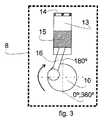
図3は圧縮機構8を示しており、同機構は回転する車軸10を有し、ここにロッド16が取り付けられる。ロッド16はピストンを駆動してシリンダ13内部で移動させることで、回転車軸10の回転運動を往復動に変え、以て圧縮ガスをバルブプレート14を介して循環させる。この機構は、高い圧力差と高い反作用トルクのピークが生じるようにガスを圧縮する。回転車軸10の回転運動は、それ自身の慣性によって保持され、その平均速度は、モータ9が発生したトルクによって維持される。 FIG. 3 shows a
図4は、モータ9によって生成されかつ圧縮機構8の反作用トルク21と直面する運転トルク20を示しており、反作用トルクは往復圧縮機3の回転車軸10の回転速度23の変動を発生するようになっている。回転車軸10のこの回転速度23は圧縮サイクル/ストロークを通して変化するものであり、その圧縮サイクルは通常、回転角が0度となるピストン15の下死点で始まり、回転の180度に近いほぼ低角度において車軸を減速させて最大圧縮と最大反作用トルクに到達する。 FIG. 4 shows the
図5から分かるように、従来技術による往復圧縮機3の停止過程の間では、モータ9が作動トルク20の生成を止める瞬間に、圧縮機構8は、回転車軸10に蓄えられた運動エネルギによる慣性運動を継続し、回転車軸10の回転速度23は圧縮サイクルが終了する毎に徐々に減少し、回転車軸の回転がかなり減少したために圧縮サイクルを完了するほど充分なエネルギがなくなるような衝撃時期24に至るまで、回転する質量車軸10から運動エネルギを抜き出す。 As can be seen from FIG. 5, during the stopping process of the reciprocating
このため、回転する車軸10は急激に回転速度23をなくし、即ち高い減速(rpm/s)が起こり、衝撃時期24において圧縮機構8の逆衝撃を引き起こす。非常に短い期間内での圧縮機構8の減速は機械アセンブリ12全体を駆動し、回転車軸10を反対方向に回転させるかもしれない。回転車軸10の運動エネルギは、回転(角)と回転軸10の慣性力に依存する。急停止で生じた逆の衝撃は、機械アセンブリ12に強い衝撃を与え、このようにして機械アセンブリ12とハウジング17の間に大きな変位と、場合によっては機械的衝撃を起こし、これにより騒音とサスペンションスプリング11の疲労を発生させる。 For this reason, the rotating
図6は、逆の方法で、指摘した問題の解決策を示した、本発明によるグラフを示しており、ここでは往復圧縮機3の停止過程の間、モータ9が作動トルクの発生を停止した制動時期32において、圧縮機構8は、回転車軸10に蓄えられた運動エネルギよってその慣性運動を続けており、回転車軸10の回転速度23は、回転車軸10の回転が速度レベル34より下になるまでは徐々に減少している状態を示している。電子制御装置2が、回転車軸10の回転が速度レベル34に到達したことを検知したならば、続く時期35において電子制御装置2は反対方向の制動トルク36を圧縮機構8の回転に付与する。 FIG. 6 shows a graph according to the invention showing the solution of the problem pointed out in the opposite way, in which the
好ましくは、この検出は、ロータ位置の変化の間の時間を検出する電子制御装置2によってなされる。図5及び図6から分かるように、ピストンのストローク期間(0°〜360°)は速度に反比例して変化する。したがって、電子制御装置2は、圧縮機構8がその運動(0°〜360°)を実行する必要がある期間を検出し、その期間の最大基準時間と比較するように構成すればよい。この最大基準時間は、圧縮機構8が速度レベル34でその運動を実行する必要がある期間に関係する。従って、回転車軸10の回転速度が電子制御装置2により予め設定された速度レベル34を下回った時、制動トルク36が付与されるということができる。本発明の好ましい実施形態では、制動トルク36は通常、反作用トルク31がその最大値(ピーク)の1つを通った時、適用され、既に減速下にあるモータ9の慣性を利用することで制動を容易にしている。この制動トルク36の最も関連性のある特徴は、モータ9巻線を循環する電流レベルに依存するその強度と、速度レベル34に到達した瞬間からモータ9が完全停止するまで続くかもしれないその継続時間にある。 Preferably, this detection is made by an
制動トルク36は様々な方法によって付与することができる。モータ9の巻線間に抵抗を追加し、モータ9動作によって生じる電流を閉じ回路に循環させてその動作とは逆のトルクを発生する方法(モータ9を制御するインバータのPWM変調によっても実行可能)や、或いは運転中、モータ9に供される電流とは逆の電流を与える方法が採用されることが好ましい。 The braking
速度レベル34に続くこの継続期間35には、回転車軸10の制動期間37を始め、回転車軸10の最後の回転の多くが含まれる。このようにして、最後の圧縮サイクルが生じることが回避され、以て圧縮機構8へ強い逆衝撃がかかるのも防止される。このようにして回転車軸10は減速され、その減速は制御された形で最後の回転の至るところへと分散され、結果として昨今の技術で見られるような値よりも実質的に低い減速値(rpm/s)が得られることになる。この事象を起こすためには、回転車軸10の回転速度レベル34は、往復圧縮機3の回転軸車10に蓄えられた運動エネルギによって完全な圧縮サイクルが完了されるほど十分であることが好ましく、以て圧縮機構8の突然の減速やショックを回避できるものでなければならない。 This
このようにして、本発明によれば、機械アセンブリ12のサスペンションスプリング11を、振動をフィルタリングするのに非常に効果的な低弾性係数を持つように設計することができ、さらに往復圧縮機3のハウジング17と伴う機械アセンブリ12のショックを回避する。加えて、本発明は、停止過渡中において機械アセンブリ12が大きく変位するのを防止し、サスペンションスプリング11に加わる機械的な応力や疲労を最小限に抑える。 In this way, according to the present invention, the
従って、本発明は、回転する車軸の最後の回転中、ロッド/クランク/ピストンからなるアセンブリの減速を制御することによって、停止の際の圧縮機の機械アセンブリにかかるショックを大幅に低減する(或いは無くする)システム及び方法を規定するものであり、これにより、ピストンが最後の不完全なガス圧縮サイクル中において急激に減速するのを回避すると共に、トルクを伴った高い衝撃の発生を防止するものである。 Thus, the present invention greatly reduces the shock on the compressor mechanical assembly during a stop by controlling the deceleration of the rod / crank / piston assembly during the final rotation of the rotating axle (or System) and method to prevent the piston from decelerating rapidly during the last incomplete gas compression cycle and to prevent the occurrence of high impact with torque It is.
以上、本発明の好ましい実施例を説明したが、本発明の範囲は、添付した請求項の中身によってのみ限定された形で、考えられ得る等価物を含んだその他の予想可能な変形例を包含していることを理解すべきである。 Although the preferred embodiment of the present invention has been described above, the scope of the present invention is limited only by the content of the appended claims and includes other possible variations including possible equivalents. You should understand that.
本発明は、往復圧縮機の停止(制動)動作を制御することができるシステム及びシステムに関する。 The present invention relates to a system and a system capable of controlling a stop (braking) operation of a reciprocating compressor.
往復型密閉圧縮機は往復動型のロッド、クランク及びピストンを有し、一般家庭や営利業界の冷房装置に広く使用されている。 A reciprocating hermetic compressor has a reciprocating rod, a crank, and a piston, and is widely used for cooling devices in general households and commercial industries.
往復圧縮機は、2つの一定速度状態(オン/オフ)の制御が最高温度での圧縮機オンと、最低温度での圧縮機オフによって実行されるような固定容量型圧縮機の場合があり、またその制御がある電気機械装置や電子回路によって実行されかつ例えばコンパートメントの内部温度などの冷房装置用制御変数に依存するプログラムに対応でき圧縮機が変化する速度と制動の往復動サイクルで作動するような変動容量型圧縮機の場合もある。 A reciprocating compressor may be a fixed capacity compressor in which control of two constant speed states (on / off) is performed by turning on the compressor at the highest temperature and turning off the compressor at the lowest temperature, It can also handle programs that are executed by some electromechanical device or electronic circuit and depend on control variables for the cooling system, such as the internal temperature of the compartment, so that the compressor operates at varying speeds and reciprocating cycles of braking. There is also a case of a variable capacity compressor.
運転期間中に、往復圧縮機は、冷却回路を介して冷却ガスを循環することに関与し、ロッド・クランク・ピストン機構は、ピストンの前進によってガス圧を上げ、冷却ガスが逆の応力を同機構と回転車軸に与えるといったような周期的な運動の実行に関与する。ピストンへのこの応力と、その結果として生じる機構と回転車軸への反作用は、回転車軸の回転を通して大きく変化し、その変動は冷却ガスの圧力値に直接比例する(蒸発圧と冷却回路の凝縮圧の差が大きくなれば、それだけ変動も大きくなる)。 During operation, the reciprocating compressor is responsible for circulating the cooling gas through the cooling circuit, and the rod-crank-piston mechanism raises the gas pressure by the advance of the piston, and the cooling gas has the opposite stress. It is involved in the execution of periodic movements such as giving to the mechanism and rotating axle. This stress on the piston, and the resulting mechanism and reaction to the rotating axle, changes significantly throughout the rotation of the rotating axle, and its variation is directly proportional to the pressure value of the cooling gas (evaporation pressure and condensation pressure of the cooling circuit). The larger the difference, the greater the variation.)
このため、往復圧縮機を使用する冷房装置では、圧縮機のスイッチが切られた瞬間は、機構はアセンブリの慣性、主に回転運動を課すモータ回転子の慣性により、依然として回転する。慣性運動は、ガスの圧力差によって生じるピストンへの逆衝撃に起因して、圧縮機停止時のショックを発生させる。その衝撃は、車軸の急激な停止により起こるか、或いはストンが圧力を克服することができないために車軸の最後の回転時での反対方向の回転運動によって起こる。このように、交互運動においてガスが圧縮・非圧縮され、その状態は往復圧縮機に諸問題を生じさせる可能性がある。 For this reason, in a cooling system that uses a reciprocating compressor, the moment the compressor is switched off, the mechanism still rotates due to the inertia of the assembly, mainly the inertia of the motor rotor that imposes rotational motion. The inertial motion generates a shock when the compressor is stopped due to a reverse impact on the piston caused by a gas pressure difference. The impact can be caused by a sudden stop of the axle, or it can be caused by rotational movement in the opposite direction during the last revolution of the axle because the stone cannot overcome the pressure. As described above, the gas is compressed and uncompressed in the alternate motion, and this state may cause various problems in the reciprocating compressor.
このため、停止ショックは冷房用往復圧縮機ではよくあることである。一般的に、圧縮機内部にあってアセンブリ全体を支持するサスペンションスプリングシステムは、衝動を吸収・減衰し、部品間衝撃によるスプリング破損や停止騒音などの問題を発生しないように設計される。圧縮機が作動する圧力差が大きければそれだけ、停止衝撃も大きくなるであろう。 For this reason, stop shocks are common in reciprocating compressors for cooling. In general, a suspension spring system that is inside a compressor and supports the entire assembly is designed to absorb and dampen impulses and prevent problems such as spring breakage and stop noise due to impact between components. The greater the pressure differential at which the compressor operates, the greater the stop impact.
圧縮機が停止する際のショックの問題に対する技術的解決法の一つは、サスペンションスプリングにおけるバランスのとれた設計である。そのサスペンションスプリングの主な機能は、ポンプ装置の通常作動中においてピストンの往復動によって発生する振動の伝達を減衰することにあり、以てこれらの振動が外側圧縮機ボディに移り、最終的にはクーラーに伝わって騒音を発生するのを防止することにある。このような方法では、スプリングは、停止衝撃を吸収する以外に、正常機能振動を減衰するのに充分なほど柔らかでなくてはならない。他方、スプリングはこの停止衝撃の間、アセンブリを長く変位させる地点まで過度に柔軟なように設計すべきではない。何故なら過度に柔軟であると機械的停止の際に衝撃を生じ、騒音を発生してしまう可能性があるからである。同様に、スプリングの疲労や破壊を起こす程度まで過剰な応力がスプリングに生じないような設計が採択されなければならない。 One technical solution to the shock problem when the compressor stops is a balanced design in the suspension spring. The main function of the suspension spring is to dampen the transmission of vibrations generated by the reciprocating movement of the pistons during normal operation of the pump device, so that these vibrations move to the outer compressor body and eventually It is to prevent noise from being transmitted to the cooler. In such a method, the spring must be soft enough to damp normal function vibrations in addition to absorbing the stop impact. On the other hand, the spring should not be designed to be overly flexible to the point of long displacement of the assembly during this stop impact. This is because excessively flexible may cause an impact at the time of mechanical stop and generate noise. Similarly, a design that does not cause excessive stress in the spring to the extent that it causes fatigue or failure of the spring must be adopted.
ここで留意すべきことは、その停止ショックは、大きな圧力差で作動する圧縮機や、構成部品の内部質量がより小さい圧縮機にとってはより強烈なものであるかもしれないということである。尚、圧力状態やアセンブリ質量に関連する要因は、サスペンションスプリングの設計を困難にしており、通常作動の振動を減衰しようとすればそれだけ、このプロジェクトは特に低回転での作動においてより高度なものとなるであろう。このため、設計者はより深刻で達成困難な外形条件に直面している。 It should be noted that the stop shock may be more intense for compressors that operate with large pressure differentials and compressors with smaller internal mass of components. It should be noted that factors related to pressure conditions and assembly mass make suspension springs difficult to design, and that the project will be more sophisticated, especially in low-speed operation, if one tries to damp out normal operating vibrations. It will be. For this reason, designers are faced with more serious and difficult external conditions.
厳しい圧力条件やアセンブリ重量の最適化、さらに低回転運転時の騒音レベルを大幅にへらす必要、が存在する設計において、スプリング設計への解決策は全ての希望条件を満たさないかもしれない。 In designs where severe pressure conditions, assembly weight optimization, and the need to significantly reduce noise levels during low speed operation exist, the spring design solution may not meet all desired requirements.
モータの減速を制御する技術の他の例としては、米国特許第5,986,419号(特許文献1)に見ることができる。この文献は機械アセンブリの減速に制動トルクを利用しているが、その適用は回転速度はある速度レベルより下であることを検出した後に限られたものである。この速度レベルはゼロ(V=0)であるため、制動トルクはモータが間違った方向で回転している時だけ適用されるだけに過ぎず、それは全く異なる問題と解決法である。Another example of a technique for controlling the deceleration of a motor can be found in US Pat. No. 5,986,419 (Patent Document 1). This document uses braking torque to decelerate the mechanical assembly, but its application is limited after detecting that the rotational speed is below a certain speed level. Since this speed level is zero (V = 0), the braking torque is only applied when the motor is rotating in the wrong direction, which is a completely different problem and solution.
したがって、本発明の第1の目的は、サスペンションシステムにおけるスプリングの剛性を低減でき、以て通常動作時の振動レベルを最小に抑えるシステム及び方法を提供することにある。 Accordingly, it is a first object of the present invention to provide a system and method that can reduce the stiffness of a spring in a suspension system, thereby minimizing the vibration level during normal operation.
本発明の別の目的は、サスペンションシステムのロバスト性に対する要求を下げることができ、スプリングの破損を回避することで信頼性レベルと耐用年数を維持するシステム及び方法を提供することにある。 Another object of the present invention is to provide a system and method that can reduce the robustness requirements of a suspension system and maintain reliability levels and service life by avoiding spring breakage.
本発明の更なる目的は、圧縮機を高い圧力差の条件で作動させることができ、その状態の下で好ましからぬ衝撃や騒音を発生することなく圧縮機の電源を切ることができるシステム及び方法を提供することにある。 A further object of the present invention is a system and method whereby the compressor can be operated at high pressure differential conditions and the compressor can be turned off under that condition without generating undesired shocks and noise. Is to provide.
本発明の目的は、少なくとも1つの圧縮機構及び1台のモータを具備する少なくとも1つの機械アセンブリ、及び少なくとも1つの電子制御装置、を有する往復圧縮機において、前記電子制御装置は、前記圧縮機構の回転速度を検出すると共に、回転速度が所定の速度値より下であることを検出した後の圧縮機の制動過程中、制動トルクを機械アセンブリに付与するように構成され、前記制動トルクは圧縮ストロークが完了した後の次の瞬間に開始され、前記制動トルクは、新しい圧縮ストロークが今まさに始まろうとしている瞬間に前記圧縮機構の回転速度が0の値を有するように、回転速度を段階的に減速するように設定されている往復圧縮機によって達成される。An object of the present invention isto provide a reciprocating compressor having at least one mechanical assembly including at least one compression mechanism and one motor, and at least one electronic control unit, wherein the electronic control unit includes the compression mechanism. During the braking process of the compressor after detecting the rotational speed and detecting that the rotational speed is below a predetermined speed value, the braking torque is applied to the mechanical assembly, the braking torque being a compression stroke. Is started at the next moment after completion of the rotation, and the braking torque is stepped in such a way that the rotation speed of the compression mechanism has a value of zero at the moment when a new compression stroke is about to begin. This is achieved by areciprocating compressor that is set to decelerate .
さらに、上記の目的は、
(a)少なくとも圧縮機構と1台のモータを有する機械アセンブリの回転速度を検出するステップ、
(b)前記回転速度を所定の速度値と比較するステップ、及び
(c)前記回転速度が所定の速度値より下であることを検出した後の圧縮機の制動過程中、制動トルクを付与して機械アセンブリを減速させるステップであって、前記制動トルクは圧縮ストロークが完了した後の次の瞬間に開始されるような前記ステップを有し、前記ステップ(c)は、新しい圧縮ストロークが今まさに始まろうとしている瞬間に前記圧縮機構の回転速度が0の値を有するように、回転速度を段階的に減速させるように設定されるような往復圧縮機制御方法によって達成される。Furthermore, the above objective
(A) detecting a rotational speed of a mechanical assembly having at least a compression mechanism and one motor;
(B) comparing the rotational speed with a predetermined speed value; and
(C) applying a braking torque to decelerate the mechanical assembly during the braking process of the compressor after detecting that the rotational speed is below a predetermined speed value, the braking torque being a compression stroke And the step (c) is such that the rotational speed of the compression mechanism is zero at the moment when a new compression stroke is about to begin. It is achieved bya reciprocating compressor control method such that the rotational speed is set to be stepwise reduced .
上記目的はさらに、少なくとも:1つの電子制御装置、及び少なくとも1つの圧縮機構と1台のモータを備えた、少なくとも1つの機械アセンブリを有する1つの往復圧縮機、
を有すると共に、前記電子制御装置は、前記圧縮機構の回転速度を検出すると共に、回転速度が所定の速度値より下であることを検出した後の圧縮機の制動過程中、制動トルクを機械アセンブリに付与するように構成され、前記制動トルクは圧縮ストロークが完了した後の次の瞬間に開始され、前記制動トルクは、新しい圧縮ストロークが今まさに始まろうとしている瞬間に前記圧縮機構の回転速度が0の値を有するように、回転速度を段階的に減速するように設定されている冷房圧縮機制御システムによって達成される。The object further includes at least one electronic controller and one reciprocating compressor having at least one mechanical assembly comprising at least one compression mechanism and one motor,
And the electronic control unit detects the rotational speed of the compression mechanism and, during the braking process of the compressor after detecting that the rotational speed is below a predetermined speed value, The braking torque is started at the next moment after the compression stroke is completed, and the braking torque is applied at the moment the new compression stroke is about to start. This is achieved by a cooling compressor control system that is set to reduce the rotational speed in steps to have a value of zero.
以下の図面を参照し、本発明をさらに詳細に説明する。 The present invention will be described in more detail with reference to the following drawings.
図1に示すように、冷却システムは往復圧縮機3を有し、それは電力ネットワーク1によって給電され、往復圧縮機3の作動を制御可能な電子制御装置2を備える。往復圧縮機3は、ガス循環閉回路18内で冷却ガスを駆動し、この回路内で冷却ガスの流れ7を生成し、そのガスを凝縮器5にガスを導く。凝縮器5の後は、冷却ガスは例えば毛細管であるかもしれない流動冷却装置6を流れる。次いでガスは蒸発器4に導かれ、その後、往復圧縮機3に戻り、再びガス循環回路を開始させる。 As shown in FIG. 1, the cooling system includes a
図2は、圧縮機内部にあるサブシステムに焦点をあてたものであり、往復圧縮機3はハウジング17と、機械アセンブリ12の運動より発生する機械的振動を減衰するサスペンションスプリング11と、同アセンブリ12を形成するモータ9及び圧縮機構8とによって形成され、同機構及びモータはトルクと回転運動を伝達する車軸10によって相互連結されている。 FIG. 2 focuses on the subsystems inside the compressor. The
不均衡とトルク変動に起因し、圧縮機構8によって生じる機械的振動は、サスペンションスプリング11によってフィルタリングされる。このため、サスペンションスプリング11は、振動フィルタリングの効率を高めるため低弾性係数をもつように(即ち、できるだけ柔軟に)計画化される。しかしながら、仮にサスペンションスプリング11が柔軟に作られたならば、この設計は、往復圧縮機3の停止時、機械アセンブリ12の過渡振動と変位の振幅を増大させ、往復圧縮機3のハウジング17に対する機械アセンブリ12(駆動と圧縮)間の機械的衝撃を生じる恐れがあり、騒音やサスペンションスプリング11の疲労や破損を生じる可能性がある。 Mechanical vibrations caused by the
図3は圧縮機構8を示しており、同機構は回転する車軸10を有し、ここにロッド16が取り付けられる。ロッド16はピストンを駆動してシリンダ13内部で移動させることで、回転車軸10の回転運動を往復動に変え、以て圧縮ガスをバルブプレート14を介して循環させる。この機構は、高い圧力差と高い反作用トルクのピークが生じるようにガスを圧縮する。回転車軸10の回転運動は、それ自身の慣性によって保持され、その平均速度は、モータ9が発生したトルクによって維持される。 FIG. 3 shows a
図4は、モータ9によって生成されかつ圧縮機構8の反作用トルク21と直面する運転トルク20を示しており、反作用トルクは往復圧縮機3の回転車軸10の回転速度23の変動を発生するようになっている。回転車軸10のこの回転速度23は圧縮サイクル/ストロークを通して変化するものであり、その圧縮サイクル/ストロークは通常、回転角が0度となるピストン15の下死点で始まり、回転の180度に近いほぼ低角度において車軸を減速させて最大圧縮と最大反作用トルクに到達する。FIG. 4 shows the operating
図5から分かるように、従来技術による往復圧縮機3の停止過程の間では、モータ9が作動トルク20の生成を止める瞬間に、圧縮機構8は、回転車軸10に蓄えられた運動エネルギによる慣性運動を継続し、回転車軸10の回転速度23は圧縮ストロークが終了する毎に徐々に減少し、回転車軸の回転がかなり減少したために圧縮ストロークを完了するほど充分なエネルギがなくなるような衝撃時期24に至るまで、回転する質量車軸10から運動エネルギを抜き出す。As can be seen from FIG. 5, during the stopping process of the
このため、回転する車軸10は急激に回転速度23をなくし、即ち高い減速(rpm/s)が起こり、衝撃時期24において圧縮機構8の逆衝撃を引き起こす。非常に短い期間内での圧縮機構8の減速は機械アセンブリ12全体を駆動し、回転車軸10を反対方向に回転させるかもしれない。回転車軸10の運動エネルギは、回転(角)と回転軸10の慣性力に依存する。急停止で生じた逆の衝撃は、機械アセンブリ12に強い衝撃を与え、このようにして機械アセンブリ12とハウジング17の間に大きな変位と、場合によっては機械的衝撃を起こし、これにより騒音とサスペンションスプリング11の疲労を発生させる。 For this reason, the rotating
図6は、逆の方法で、指摘した問題の解決策を示した、本発明によるグラフを示しており、ここでは往復圧縮機3の停止過程の間、モータ9が作動トルクの発生を停止した制動時期32において、圧縮機構8は、回転車軸10に蓄えられた運動エネルギよってその慣性運動を続けており、回転車軸10の回転速度23は、回転車軸10の回転が予め定められた速度値34より下になるまでは徐々に減少している状態を示している。電子制御装置2が、回転車軸10の回転が予め定められた速度値34に到達したことを検知したならば、続く時期35において電子制御装置2は反対方向の制動トルク36を圧縮機構8の回転に付与する。FIG. 6 shows a graph according to the invention showing the solution of the problem pointed out in the opposite way, in which the
好ましくは、この検出は、ロータ位置の変化の間の時間を検出する電子制御装置2によってなされる。図5及び図6から分かるように、ピストンのストローク期間(0°〜360°)は速度に反比例して変化する。したがって、電子制御装置2は、圧縮機構8がその運動(0°〜360°)を実行する必要がある期間を検出し、その期間の最大基準時間と比較するように構成すればよい。この最大基準時間は、圧縮機構8が予め定められた速度値34でその運動を実行する必要がある期間に関係する。従って、回転車軸10の回転速度が電子制御装置2により予め設定された予め定められた速度値34を下回った時、制動トルク36が付与されるということができる。本発明の好ましい実施形態では、制動トルク36は通常、反作用トルク31がその最大値(ピーク)の1つを通った時、適用され、既に減速下にあるモータ9の慣性を利用することで制動を容易にしている。この制動トルク36の最も関連性のある特徴は、モータ9巻線を循環する電流レベルに依存するその強度と、予め定められた速度値34に到達した瞬間からモータ9が完全停止するまで続くかもしれないその継続時間にある。Preferably, this detection is made by an
制動トルク36は様々な方法によって付与することができる。モータ9の巻線間に抵抗を追加し、モータ9動作によって生じる電流を閉じ回路に循環させてその動作とは逆のトルクを発生する方法(モータ9を制御するインバータのPWM変調によっても実行可能)や、或いは運転中、モータ9に供される電流とは逆の電流を与える方法が採用されることが好ましい。 The braking
予め定められた速度値34に続くこの継続期間35には、回転車軸10の制動期間37を始め、回転車軸10の最後の回転の多くが含まれる。このようにして、最後の圧縮ストロークが生じることが回避され、以て圧縮機構8へ強い逆衝撃がかかるのも防止される。このようにして回転車軸10は減速され、その減速は制御された形で最後の回転の至るところへと分散され、結果として昨今の技術で見られるような値よりも実質的に低い減速値(rpm/s)が得られることになる。この事象を起こすためには、回転車軸10の予め定められた回転速度値34は、往復圧縮機3の回転軸車10に蓄えられた運動エネルギによって完全な圧縮ストロークが完了されるほど十分であることが好ましく、以て圧縮機構8の突然の減速やショックを回避できるものでなければならない。This
このようにして、本発明によれば、機械アセンブリ12のサスペンションスプリング11を、振動をフィルタリングするのに非常に効果的な低弾性係数を持つように設計することができ、さらに往復圧縮機3のハウジング17と伴う機械アセンブリ12のショックを回避する。加えて、本発明は、停止過渡中において機械アセンブリ12が大きく変位するのを防止し、サスペンションスプリング11に加わる機械的な応力や疲労を最小限に抑える。 In this way, according to the present invention, the
従って、本発明は、回転する車軸の最後の回転中、ロッド/クランク/ピストンからなるアセンブリの減速を制御することによって、停止の際の圧縮機の機械アセンブリにかかるショックを大幅に低減する(或いは無くする)システム及び方法を規定するものであり、これにより、ピストンが最後の不完全なガス圧縮ストローク中において急激に減速するのを回避すると共に、トルクを伴った高い衝撃の発生を防止するものである。Thus, the present invention greatly reduces the shock on the compressor mechanical assembly during a stop by controlling the deceleration of the rod / crank / piston assembly during the final rotation of the rotating axle (or System) and method to prevent the piston from decelerating rapidly during the last incomplete gas compressionstroke and to prevent the occurrence of high impact with torque It is.
以上、本発明の好ましい実施例を説明したが、本発明の範囲は、添付した請求項の中身によってのみ限定された形で、考えられ得る等価物を含んだその他の予想可能な変形例を包含していることを理解すべきである。 Although the preferred embodiment of the present invention has been described above, the scope of the present invention is limited only by the content of the appended claims and includes other possible variations including possible equivalents. You should understand that.
Claims (18)
Translated fromJapanese前記電子制御装置(2)は、前記圧縮機構(8)の回転速度(23)を検出すると共に、前記回転速度(23)が予め定められた速度値(34)より下であることを検出した後、制動トルク(36)を機械アセンブリ(12)に付与するように構成されていることを特徴とする制御システム。At least one electronic controller (2) and a reciprocating compressor (3) comprising at least one mechanical assembly (12) comprising at least one compression mechanism (8) and one motor (9); A control system for cooling a compressor, comprising:
The electronic control unit (2) detects the rotational speed (23) of the compression mechanism (8) and detects that the rotational speed (23) is lower than a predetermined speed value (34). Thereafter, a control system configured to apply a braking torque (36) to the mechanical assembly (12).
(a)少なくとも圧縮機構(8)と1台のモータ(9)を有する機械アセンブリ(12)の回転速度(23)を検出するステップと、
(b)前記回転速度(23)を速度値レベル(34)と比較するステップ、及び、
(c)前記回転速度(23)が速度値(34)より下であることを検出した後、制動トルク(36)を付与して機械アセンブリ(12)を減速させるステップを有することを特徴とする密閉した冷房圧縮機のための制御方法。In a control method for a hermetic cooling compressor,
(A) detecting a rotational speed (23) of a mechanical assembly (12) having at least a compression mechanism (8) and one motor (9);
(B) comparing the rotational speed (23) with a speed value level (34); and
(C) after detecting that the rotational speed (23) is lower than the speed value (34), applying a braking torque (36) to decelerate the mechanical assembly (12). Control method for hermetic cooling compressor.
Applications Claiming Priority (3)
| Application Number | Priority Date | Filing Date | Title |
|---|---|---|---|
| BRPI1100026-0ABRPI1100026A2 (en) | 2011-01-26 | 2011-01-26 | reciprocal compressor system and control method |
| BRPI1100026-0 | 2011-01-26 | ||
| PCT/BR2012/000014WO2012100313A1 (en) | 2011-01-26 | 2012-01-25 | Control system and method for reciprocating compressors |
Related Child Applications (1)
| Application Number | Title | Priority Date | Filing Date |
|---|---|---|---|
| JP2016087880ADivisionJP6174753B2 (en) | 2011-01-26 | 2016-04-26 | Reciprocating compressor control system and method |
Publications (2)
| Publication Number | Publication Date |
|---|---|
| JP2014507589Atrue JP2014507589A (en) | 2014-03-27 |
| JP6030576B2 JP6030576B2 (en) | 2016-11-24 |
Family
ID=45872751
Family Applications (2)
| Application Number | Title | Priority Date | Filing Date |
|---|---|---|---|
| JP2013550708AActiveJP6030576B2 (en) | 2011-01-26 | 2012-01-25 | Reciprocating compressor control system and method for cooling |
| JP2016087880AExpired - Fee RelatedJP6174753B2 (en) | 2011-01-26 | 2016-04-26 | Reciprocating compressor control system and method |
Family Applications After (1)
| Application Number | Title | Priority Date | Filing Date |
|---|---|---|---|
| JP2016087880AExpired - Fee RelatedJP6174753B2 (en) | 2011-01-26 | 2016-04-26 | Reciprocating compressor control system and method |
Country Status (12)
| Country | Link |
|---|---|
| US (1) | US10590925B2 (en) |
| EP (3) | EP2957770B1 (en) |
| JP (2) | JP6030576B2 (en) |
| KR (1) | KR20140004691A (en) |
| CN (3) | CN103403349B (en) |
| AR (1) | AR084928A1 (en) |
| BR (2) | BRPI1100026A2 (en) |
| DE (1) | DE202012013046U1 (en) |
| ES (2) | ES2551398T3 (en) |
| SG (1) | SG192003A1 (en) |
| TR (1) | TR201900678T4 (en) |
| WO (1) | WO2012100313A1 (en) |
Cited By (2)
| Publication number | Priority date | Publication date | Assignee | Title |
|---|---|---|---|---|
| JP6331183B1 (en)* | 2017-11-22 | 2018-05-30 | 新日本特機株式会社 | Brake torque generator for electric vehicle and electric vehicle |
| JP6457684B1 (en)* | 2017-11-22 | 2019-01-23 | 新日本特機株式会社 | Brake torque generator for electric vehicle and electric vehicle |
Families Citing this family (16)
| Publication number | Priority date | Publication date | Assignee | Title |
|---|---|---|---|---|
| BRPI1100026A2 (en) | 2011-01-26 | 2013-04-24 | Whirlpool Sa | reciprocal compressor system and control method |
| EP3054158A1 (en)* | 2015-02-09 | 2016-08-10 | Secop GmbH | Method for stopping a hermetic refrigerant compressor and control system for same |
| DE102015215972A1 (en) | 2015-08-21 | 2017-02-23 | BSH Hausgeräte GmbH | Domestic refrigeration appliance with a refrigerant circuit and method for operating a household refrigerator with a refrigerant circuit |
| DE102015221881A1 (en) | 2015-11-06 | 2017-05-11 | BSH Hausgeräte GmbH | Domestic refrigeration appliance with a refrigerant circuit and method for operating a household refrigerator with a refrigerant circuit |
| CN105370559B (en)* | 2015-12-03 | 2017-08-01 | 浙江工业大学 | Measuring device and method for no-load torque of reciprocating mechanical mechanism of refrigeration compressor |
| EP3199809B1 (en)* | 2016-01-28 | 2021-06-09 | ABB Schweiz AG | Control method for a compressor system |
| US10436226B2 (en)* | 2016-02-24 | 2019-10-08 | Emerson Climate Technologies, Inc. | Compressor having sound control system |
| EP3282126B1 (en) | 2016-03-30 | 2019-08-21 | Nidec Global Appliance Germany GmbH | Electronic control device for a refrigerant compressor |
| DE102016222958A1 (en) | 2016-11-22 | 2018-05-24 | BSH Hausgeräte GmbH | Method for stopping a reciprocating compressor and reciprocating compressor of a refrigeration device, air conditioner or a heat pump and refrigeration device, air conditioner or heat pump with it |
| WO2018114978A1 (en)* | 2016-12-19 | 2018-06-28 | Nidec Global Appliance Germany Gmbh | Control device and method for operating a refrigerant compressor |
| CN110300850B (en)* | 2016-12-19 | 2021-06-15 | 思科普有限公司 | Control device and method for operating a refrigerant compressor |
| EP3534000B1 (en)* | 2018-03-01 | 2020-08-05 | Secop GmbH | System containing a refrigerant compressor, and method for operating the refrigerant compressor |
| BR102019027356A2 (en)* | 2019-12-19 | 2021-06-29 | Embraco Indústria De Compressores E Soluções Em Refrigeração Ltda. | NOISE REDUCTION METHOD AND SYSTEM AND PISTON POSITIONING IN ENGINE START FAILURE |
| KR102342001B1 (en)* | 2020-05-26 | 2021-12-24 | 어보브반도체 주식회사 | Control apparatus of compressor and method for controlling compressor |
| US12123803B2 (en)* | 2020-08-27 | 2024-10-22 | University Of Idaho | Rapid compression machine with electrical drive and methods for use thereof |
| CN116324168A (en)* | 2020-11-09 | 2023-06-23 | 海德鲁西昂公司 | Motor speed control system, device and method |
Citations (6)
| Publication number | Priority date | Publication date | Assignee | Title |
|---|---|---|---|---|
| JPS60153483A (en)* | 1984-01-20 | 1985-08-12 | Mitsubishi Heavy Ind Ltd | Method of stopping electric compressor |
| US5986419A (en)* | 1996-07-15 | 1999-11-16 | General Electric Company | Quadrature axis winding for sensorless rotor angular position control of single phase permanent magnet motor |
| JP2001037281A (en)* | 1999-05-18 | 2001-02-09 | Matsushita Electric Ind Co Ltd | Motor torque control device |
| US20030180148A1 (en)* | 2002-03-21 | 2003-09-25 | Kendro Laboratory Products, Inc. | Device for prevention of backward operation of scroll compressors |
| WO2004083744A1 (en)* | 2003-03-17 | 2004-09-30 | Matsushita Electric Industrial Co. Ltd. | Air conditioner |
| JP2010270700A (en)* | 2009-05-22 | 2010-12-02 | Nissan Motor Co Ltd | Stop control device for compressor for fuel cell |
Family Cites Families (23)
| Publication number | Priority date | Publication date | Assignee | Title |
|---|---|---|---|---|
| US3540813A (en) | 1969-03-27 | 1970-11-17 | Bendix Westinghouse Automotive | Mounting support for hermetic motor compressors |
| US4355959A (en)* | 1979-10-26 | 1982-10-26 | Kabushiki Kaisha Toyoda Jidoshokki Seisakusho | Rotation sensor of a swash-plate type compressor |
| US5220259A (en)* | 1991-10-03 | 1993-06-15 | Graco Inc. | Dc motor drive system and method |
| JPH07167076A (en) | 1993-12-17 | 1995-07-04 | Sanyo Electric Co Ltd | Electric motor-driven compression device |
| MY122977A (en) | 1995-03-14 | 2006-05-31 | Panasonic Corp | Refrigerating apparatus, and refrigerator control and brushless motor starter used in same |
| JPH09121590A (en)* | 1995-09-14 | 1997-05-06 | Copeland Corp | Rotary compressor provided with counter-current braking mechanism |
| DE19654084C1 (en)* | 1996-12-23 | 1998-04-23 | Lang Apparatebau Gmbh | Method of increasing dosing accuracy of liquid dosing pump driven by asynchronous motor with eccentric gear |
| JP2000287485A (en)* | 1999-03-30 | 2000-10-13 | Toshiba Corp | Compressor motor control device for air conditioner |
| KR100414093B1 (en)* | 2001-08-01 | 2004-01-07 | 엘지전자 주식회사 | Velocity control apparatus for reciprocating compressor |
| KR100414095B1 (en)* | 2001-08-01 | 2004-01-07 | 엘지전자 주식회사 | Top dead center control apparatus for reciprocating compressor |
| JP3941452B2 (en)* | 2001-10-17 | 2007-07-04 | 株式会社豊田自動織機 | Operation stop control method and operation stop control device for vacuum pump |
| US6544017B1 (en) | 2001-10-22 | 2003-04-08 | Tecumseh Products Company | Reverse rotation brake for scroll compressor |
| KR100480118B1 (en)* | 2002-10-04 | 2005-04-06 | 엘지전자 주식회사 | Stroke detecting apparatus and method for reciprocating compressor |
| JP2006112340A (en)* | 2004-10-15 | 2006-04-27 | Mitsubishi Heavy Ind Ltd | Pressure machine, method of suppressing vibration thereof, and fluid machine |
| US7300257B2 (en)* | 2004-12-20 | 2007-11-27 | Carrier Corporation | Prevention of unpowered reverse rotation in compressors |
| JP4559241B2 (en)* | 2005-01-21 | 2010-10-06 | 株式会社神戸製鋼所 | Refrigeration equipment |
| US7922457B2 (en)* | 2005-02-26 | 2011-04-12 | Ingersoll-Rand Company | System and method for controlling a variable speed compressor during stopping |
| JP2007092686A (en)* | 2005-09-29 | 2007-04-12 | Sharp Corp | Compressor drive unit |
| US8027751B2 (en)* | 2007-07-16 | 2011-09-27 | Delphi Technologies Holding S.Arl | Fluid delivery system |
| US20090092501A1 (en)* | 2007-10-08 | 2009-04-09 | Emerson Climate Technologies, Inc. | Compressor protection system and method |
| JP4940104B2 (en)* | 2007-10-30 | 2012-05-30 | 株式会社東芝 | Compressor control device |
| US10100827B2 (en)* | 2008-07-28 | 2018-10-16 | Eaton Intelligent Power Limited | Electronic control for a rotary fluid device |
| BRPI1100026A2 (en)* | 2011-01-26 | 2013-04-24 | Whirlpool Sa | reciprocal compressor system and control method |
- 2011
- 2011-01-26BRBRPI1100026-0Apatent/BRPI1100026A2/ennot_activeApplication Discontinuation
- 2012
- 2012-01-25BRBR112013018718-2Apatent/BR112013018718B1/enactiveIP Right Grant
- 2012-01-25DEDE202012013046.3Upatent/DE202012013046U1/ennot_activeExpired - Lifetime
- 2012-01-25EPEP15001898.4Apatent/EP2957770B1/enactiveActive
- 2012-01-25USUS13/982,126patent/US10590925B2/enactiveActive
- 2012-01-25CNCN201280006608.4Apatent/CN103403349B/enactiveActive
- 2012-01-25ESES12709775.6Tpatent/ES2551398T3/enactiveActive
- 2012-01-25WOPCT/BR2012/000014patent/WO2012100313A1/enactiveApplication Filing
- 2012-01-25JPJP2013550708Apatent/JP6030576B2/enactiveActive
- 2012-01-25SGSG2013054598Apatent/SG192003A1/enunknown
- 2012-01-25CNCN201610022973.4Apatent/CN105649930A/enactivePending
- 2012-01-25EPEP18206545.8Apatent/EP3462022B1/enactiveActive
- 2012-01-25KRKR1020137019503Apatent/KR20140004691A/ennot_activeAbandoned
- 2012-01-25CNCN201510619851.9Apatent/CN105156296B/enactiveActive
- 2012-01-25TRTR2019/00678Tpatent/TR201900678T4/enunknown
- 2012-01-25ESES15001898Tpatent/ES2713227T3/enactiveActive
- 2012-01-25EPEP12709775.6Apatent/EP2669519B1/enactiveActive
- 2012-01-26ARARP120100262Apatent/AR084928A1/ennot_activeApplication Discontinuation
- 2016
- 2016-04-26JPJP2016087880Apatent/JP6174753B2/ennot_activeExpired - Fee Related
Patent Citations (7)
| Publication number | Priority date | Publication date | Assignee | Title |
|---|---|---|---|---|
| JPS60153483A (en)* | 1984-01-20 | 1985-08-12 | Mitsubishi Heavy Ind Ltd | Method of stopping electric compressor |
| US5986419A (en)* | 1996-07-15 | 1999-11-16 | General Electric Company | Quadrature axis winding for sensorless rotor angular position control of single phase permanent magnet motor |
| JP2001037281A (en)* | 1999-05-18 | 2001-02-09 | Matsushita Electric Ind Co Ltd | Motor torque control device |
| US20030180148A1 (en)* | 2002-03-21 | 2003-09-25 | Kendro Laboratory Products, Inc. | Device for prevention of backward operation of scroll compressors |
| WO2004083744A1 (en)* | 2003-03-17 | 2004-09-30 | Matsushita Electric Industrial Co. Ltd. | Air conditioner |
| JPWO2004083744A1 (en)* | 2003-03-17 | 2006-06-22 | 松下電器産業株式会社 | Air conditioner |
| JP2010270700A (en)* | 2009-05-22 | 2010-12-02 | Nissan Motor Co Ltd | Stop control device for compressor for fuel cell |
Cited By (3)
| Publication number | Priority date | Publication date | Assignee | Title |
|---|---|---|---|---|
| JP6331183B1 (en)* | 2017-11-22 | 2018-05-30 | 新日本特機株式会社 | Brake torque generator for electric vehicle and electric vehicle |
| JP6457684B1 (en)* | 2017-11-22 | 2019-01-23 | 新日本特機株式会社 | Brake torque generator for electric vehicle and electric vehicle |
| WO2019102633A1 (en)* | 2017-11-22 | 2019-05-31 | 新日本特機株式会社 | Braking torque generation device for electric vehicle and electric vehicle |
Also Published As
| Publication number | Publication date |
|---|---|
| BRPI1100026A2 (en) | 2013-04-24 |
| SG192003A1 (en) | 2013-08-30 |
| US20140072451A1 (en) | 2014-03-13 |
| BR112013018718A2 (en) | 2016-10-25 |
| CN105156296B (en) | 2017-05-17 |
| EP2957770A1 (en) | 2015-12-23 |
| DE202012013046U1 (en) | 2014-09-15 |
| KR20140004691A (en) | 2014-01-13 |
| EP2957770B1 (en) | 2019-01-02 |
| JP2016145580A (en) | 2016-08-12 |
| ES2713227T3 (en) | 2019-05-20 |
| JP6030576B2 (en) | 2016-11-24 |
| WO2012100313A1 (en) | 2012-08-02 |
| EP2669519B1 (en) | 2015-07-29 |
| CN103403349A (en) | 2013-11-20 |
| CN105649930A (en) | 2016-06-08 |
| US10590925B2 (en) | 2020-03-17 |
| EP3462022A1 (en) | 2019-04-03 |
| ES2551398T3 (en) | 2015-11-18 |
| CN105156296A (en) | 2015-12-16 |
| AR084928A1 (en) | 2013-07-10 |
| JP6174753B2 (en) | 2017-08-02 |
| EP2669519A1 (en) | 2013-12-04 |
| EP3462022B1 (en) | 2020-09-09 |
| BR112013018718B1 (en) | 2020-03-31 |
| CN103403349B (en) | 2016-02-17 |
| TR201900678T4 (en) | 2019-02-21 |
Similar Documents
| Publication | Publication Date | Title |
|---|---|---|
| JP6174753B2 (en) | Reciprocating compressor control system and method | |
| CN100529362C (en) | Electrically driven camshaft adjuster | |
| JP4525918B2 (en) | Damping force generating system and vehicle suspension system including the same | |
| CN111396278B (en) | Valve timing in electronically commutated hydraulic press | |
| CN109312730B (en) | Electronic control device for refrigerant compressor | |
| KR20200060949A (en) | Active suspension system for vehicle | |
| JP4920670B2 (en) | Hermetic compressor | |
| WO2016192974A1 (en) | Compressor with a movable oil suction apparatus and a control method | |
| CN110300850B (en) | Control device and method for operating a refrigerant compressor | |
| WO2016192976A1 (en) | Compressor with a movable oil suction apparatus | |
| CN209129806U (en) | A kind of high stable type piston compressor eccentric disc | |
| JP2021050704A (en) | Fluid operation machine and vehicle having fluid operation machine | |
| JP5579676B2 (en) | Hermetic compressor and refrigerator using the same | |
| JP2011236999A (en) | Bearing structure of rotary machine, revolving speed control device, and refrigerating cycle control device | |
| JP5389010B2 (en) | Air conditioner compressor | |
| CN208348013U (en) | A kind of drive disk of automobile air conditioner compressor | |
| KR20210117573A (en) | Compressor | |
| JP2020076468A (en) | Vibration control device and control method of vibration control device | |
| JP2008121553A (en) | Compressor | |
| JP2020067176A (en) | Vehicular power transmission device | |
| RO132353B1 (en) | System and method for variation and control of inertial mass of a flywheel meant for an engine of transportation means | |
| JPS61106994A (en) | Rotary compressor rotation speed control method | |
| JP2010242590A (en) | Hermetic compressor | |
| KR20150102259A (en) | Power transmission device of clutchless compressor |
Legal Events
| Date | Code | Title | Description |
|---|---|---|---|
| A621 | Written request for application examination | Free format text:JAPANESE INTERMEDIATE CODE: A621 Effective date:20150108 | |
| A977 | Report on retrieval | Free format text:JAPANESE INTERMEDIATE CODE: A971007 Effective date:20151022 | |
| A131 | Notification of reasons for refusal | Free format text:JAPANESE INTERMEDIATE CODE: A131 Effective date:20151027 | |
| A601 | Written request for extension of time | Free format text:JAPANESE INTERMEDIATE CODE: A601 Effective date:20160127 | |
| A521 | Request for written amendment filed | Free format text:JAPANESE INTERMEDIATE CODE: A523 Effective date:20160426 | |
| TRDD | Decision of grant or rejection written | ||
| A01 | Written decision to grant a patent or to grant a registration (utility model) | Free format text:JAPANESE INTERMEDIATE CODE: A01 Effective date:20160920 | |
| A61 | First payment of annual fees (during grant procedure) | Free format text:JAPANESE INTERMEDIATE CODE: A61 Effective date:20161020 | |
| R150 | Certificate of patent or registration of utility model | Ref document number:6030576 Country of ref document:JP Free format text:JAPANESE INTERMEDIATE CODE: R150 | |
| S111 | Request for change of ownership or part of ownership | Free format text:JAPANESE INTERMEDIATE CODE: R313113 | |
| R360 | Written notification for declining of transfer of rights | Free format text:JAPANESE INTERMEDIATE CODE: R360 | |
| R360 | Written notification for declining of transfer of rights | Free format text:JAPANESE INTERMEDIATE CODE: R360 | |
| R371 | Transfer withdrawn | Free format text:JAPANESE INTERMEDIATE CODE: R371 | |
| S111 | Request for change of ownership or part of ownership | Free format text:JAPANESE INTERMEDIATE CODE: R313113 | |
| R350 | Written notification of registration of transfer | Free format text:JAPANESE INTERMEDIATE CODE: R350 | |
| R250 | Receipt of annual fees | Free format text:JAPANESE INTERMEDIATE CODE: R250 | |
| R250 | Receipt of annual fees | Free format text:JAPANESE INTERMEDIATE CODE: R250 | |
| R250 | Receipt of annual fees | Free format text:JAPANESE INTERMEDIATE CODE: R250 | |
| R250 | Receipt of annual fees | Free format text:JAPANESE INTERMEDIATE CODE: R250 | |
| R250 | Receipt of annual fees | Free format text:JAPANESE INTERMEDIATE CODE: R250 | |
| R250 | Receipt of annual fees | Free format text:JAPANESE INTERMEDIATE CODE: R250 | |
| S533 | Written request for registration of change of name | Free format text:JAPANESE INTERMEDIATE CODE: R313533 | |
| R350 | Written notification of registration of transfer | Free format text:JAPANESE INTERMEDIATE CODE: R350 | |
| R250 | Receipt of annual fees | Free format text:JAPANESE INTERMEDIATE CODE: R250 |