JP2014504468A - 2D to 3D conversion method based on image motion information - Google Patents
2D to 3D conversion method based on image motion informationDownload PDFInfo
- Publication number
- JP2014504468A JP2014504468AJP2013540213AJP2013540213AJP2014504468AJP 2014504468 AJP2014504468 AJP 2014504468AJP 2013540213 AJP2013540213 AJP 2013540213AJP 2013540213 AJP2013540213 AJP 2013540213AJP 2014504468 AJP2014504468 AJP 2014504468A
- Authority
- JP
- Japan
- Prior art keywords
- image
- value
- pixel
- depth
- motion information
- Prior art date
- Legal status (The legal status is an assumption and is not a legal conclusion. Google has not performed a legal analysis and makes no representation as to the accuracy of the status listed.)
- Pending
Links
Images


Classifications
- H—ELECTRICITY
- H04—ELECTRIC COMMUNICATION TECHNIQUE
- H04N—PICTORIAL COMMUNICATION, e.g. TELEVISION
- H04N13/00—Stereoscopic video systems; Multi-view video systems; Details thereof
- H04N13/10—Processing, recording or transmission of stereoscopic or multi-view image signals
- H04N13/106—Processing image signals
- H04N13/128—Adjusting depth or disparity
- G—PHYSICS
- G06—COMPUTING OR CALCULATING; COUNTING
- G06T—IMAGE DATA PROCESSING OR GENERATION, IN GENERAL
- G06T7/00—Image analysis
- G06T7/50—Depth or shape recovery
- G06T7/55—Depth or shape recovery from multiple images
- G06T7/579—Depth or shape recovery from multiple images from motion
- G—PHYSICS
- G06—COMPUTING OR CALCULATING; COUNTING
- G06T—IMAGE DATA PROCESSING OR GENERATION, IN GENERAL
- G06T7/00—Image analysis
- G06T7/20—Analysis of motion
- G06T7/223—Analysis of motion using block-matching
- G06T7/238—Analysis of motion using block-matching using non-full search, e.g. three-step search
- H—ELECTRICITY
- H04—ELECTRIC COMMUNICATION TECHNIQUE
- H04N—PICTORIAL COMMUNICATION, e.g. TELEVISION
- H04N13/00—Stereoscopic video systems; Multi-view video systems; Details thereof
- H04N13/20—Image signal generators
- H04N13/261—Image signal generators with monoscopic-to-stereoscopic image conversion
- H04N13/264—Image signal generators with monoscopic-to-stereoscopic image conversion using the relative movement of objects in two video frames or fields
- G—PHYSICS
- G06—COMPUTING OR CALCULATING; COUNTING
- G06T—IMAGE DATA PROCESSING OR GENERATION, IN GENERAL
- G06T2207/00—Indexing scheme for image analysis or image enhancement
- G06T2207/20—Special algorithmic details
- G06T2207/20021—Dividing image into blocks, subimages or windows
- H—ELECTRICITY
- H04—ELECTRIC COMMUNICATION TECHNIQUE
- H04N—PICTORIAL COMMUNICATION, e.g. TELEVISION
- H04N2213/00—Details of stereoscopic systems
- H04N2213/003—Aspects relating to the "2D+depth" image format
Landscapes
- Engineering & Computer Science (AREA)
- Multimedia (AREA)
- Computer Vision & Pattern Recognition (AREA)
- Physics & Mathematics (AREA)
- General Physics & Mathematics (AREA)
- Theoretical Computer Science (AREA)
- Signal Processing (AREA)
- Testing, Inspecting, Measuring Of Stereoscopic Televisions And Televisions (AREA)
- Processing Or Creating Images (AREA)
Abstract
Translated fromJapaneseDescription
Translated fromJapanese本発明は2Dから3Dに変換する技術分野に関する、特に、画像運動情報に基づく2Dから3Dへの変換方法に関する。 The present invention relates to the technical field of converting 2D to 3D, and more particularly to a 2D to 3D conversion method based on image motion information.
スリーディー(Three Dimensions、3D)テレビが席巻してきて、世界のテレビ産業の新しい発展方向となり、各大手テレビメーカーは相次いで各自の3Dテレビを開発してきた。3D技術の応用は生活の中でますます人気が高まり、3D映画が絶えず制作されているが、3Dビデオ素材はまだ現在の市場ニーズを満足できない。ツーディー(Two Dimensions、2D)ビデオ素材を自動的に3Dに変換することは、新たな市場ニーズとなった。2Dから3Dへの変換は即ち2D画像内容に基づく第二画像・ビデオを作成することであり、この過程は、深度推定により深度マップ(depth map/image)を得ることと、深度マップに基づき画像を再構築する(Depth Image Based Rendering, DIBR)ことの二つの処理を含む。深度マップには8ビットのグレー値で深度情報が格納されている(グレー値0は最も遠い値であり、グレー値255は最も近い値である)。近年に、2Dから3Dへの変換の分野には、たくさんのアルゴリズムが開発され、運動推定に基づく2Dから3Dへの変換アルゴリズムがよく用いられる。この方法は、運動推定の方法により入力された画像の深度マップを得る。但し、深度マップはかなりの密度と精度を必要とするが、従来の、運動推定に基づく2Dから3Dへの変換アルゴリズムにより得られる深度マップは疎らであるため、物体を分解する時、異なる物体を区別できないので、DIBRによる画像の品質を影響する。従って、この方法が広く使用されることに制限がある。 Three Dimensions (3D) TV has swept over and became the new development direction of the global TV industry, and each major TV manufacturer has developed its own 3D TV one after another. Although the application of 3D technology is becoming more and more popular in life and 3D movies are constantly being produced, 3D video material still cannot meet the current market needs. The automatic conversion of 2D video material to 3D has become a new market need. The conversion from 2D to 3D is to create a second image / video based on the 2D image content, and this process involves obtaining a depth map / image by depth estimation and image based on the depth map. It includes two processes of reconstructing (Depth Image Based Rendering, DIBR). Depth information is stored in the depth map as 8-bit gray values (gray value 0 is the farthest value, and gray value 255 is the nearest value). In recent years, many algorithms have been developed in the field of 2D to 3D conversion, and 2D to 3D conversion algorithms based on motion estimation are often used. This method obtains a depth map of an image input by a motion estimation method. However, the depth map requires considerable density and accuracy, but the depth map obtained by the conventional 2D to 3D conversion algorithm based on motion estimation is sparse, so when disassembling objects, different objects are Since it cannot be distinguished, it affects the image quality by DIBR. Therefore, there is a limit to how widely this method can be used.
本発明は、画像運動情報に基づく2Dから3Dへの変換方法により得られる画像の品質を向上させることを目的とする。 An object of the present invention is to improve the quality of an image obtained by a 2D to 3D conversion method based on image motion information.
上記の課題を解決するために、本発明は、画像運動情報に基づく2Dから3Dへの変換方法を提供する。この方法は、
運動推定の方法により、入力された2D画像における各画素の深度値を得るステップS1と、
各画素の輝度値により、前記各画素の深度値を加算し、前記の入力された2D画像の深度マップを得るステップS2と、
ステップS2により得られる深度マップにより、深度マップによる画像の再構築を行い、左目画像及び/又は右目画像を再構築するステップS3と、
ステップS4による左目画像及び右目画像を合成して出力し、3D画像を得るステップS4と、を含む。In order to solve the above problems, the present invention provides a 2D to 3D conversion method based on image motion information. This method
Step S1 to obtain the depth value of each pixel in the input 2D image by the motion estimation method,
Step S2 to obtain the depth map of the input 2D image by adding the depth value of each pixel according to the luminance value of each pixel,
Step S3 for reconstructing the image by the depth map and reconstructing the left eye image and / or the right eye image from the depth map obtained in step S2,
Step S4 that combines and outputs the left-eye image and the right-eye image in Step S4 to obtain a 3D image.
好ましくは、ステップS1は、
運動推定の方法により、各画素の動きべクトルを算出するステップS1.1と、
ステップS1.1により得られる動きべクトルを用い、各画素の深度値を算出するステップS1.2と、をさらに含む。Preferably, step S1
Step S1.1 for calculating a motion vector of each pixel by a motion estimation method;
The method further includes step S1.2 of calculating the depth value of each pixel using the motion vector obtained in step S1.1.
好ましくは、前記深度値の計算式は以下の通りである。 Preferably, the formula for calculating the depth value is as follows.

好ましくは、前記運動推定の方法は、ダイヤモンド検索アルゴリズム(diamond search algorithm)である。 Preferably, the motion estimation method is a diamond search algorithm.
好ましくは、ステップS2は、
前記の入力された2D画像の一行目から、各画素の深度値を加算して、画素ごとの深度加算値D(x,y)'を得るステップS2.1と、
以下の式により、前記深度加算値を[0,255]の間に正規化して、正規化された深度値D(x,y)''を得るステップS2.2と、を更に含む。Preferably, step S2 includes
From the first row of the input 2D image, step S2.1 to obtain the depth addition value D (x, y) ′ for each pixel by adding the depth value of each pixel,
Further comprising step S2.2 of normalizing the depth addition value between [0,255] to obtain a normalized depth value D (x, y) '' according to the following equation.
(式の中に、I(x,y)は(x,y)に位置する画素の輝度値であり、その値は[0,255]の範囲にあり、SCALEは輝度値のスケーリング係数であり、widthは前記の入力された2D画像の幅であり、heightは前記の入力された2D画像の高さであり、DEPTH_SCALEは深度値のスケーリング係数であり、(In the equation, I (x, y) is the luminance value of the pixel located at (x, y), its value is in the range [0,255], SCALE is the luminance value scaling factor, and width Is the width of the input 2D image, height is the height of the input 2D image, DEPTH_SCALE is a depth value scaling factor,
好ましくは、ステップS2.1は、
yは0である場合、D(x,y)'=0であるが、そうではない場合、ステップS2.12へ進むステップS2.11と、
yは奇数である場合、且つxは0であると、D(x,y)'=D(x,y-1)'+D(x,y)であって、xは0ではないと、Preferably, step S2.1 includes
If y is 0, D (x, y) ′ = 0, but if not, step S2.11 proceeds to step S2.12, and
If y is an odd number and x is 0, then D (x, y) '= D (x, y-1)' + D (x, y), and x is not 0,
であるが、そうではない場合、ステップS2.13へ進むステップS2.12と、
x=width-1である場合、D(x,y)'=D(x,y-1)'+D(x,y)であるが、そうではない場合、If not, step S2.12 proceed to step S2.13; and
If x = width-1 then D (x, y) '= D (x, y-1)' + D (x, y), otherwise
であるステップS2.13と、
y<heightである場合、ステップS2.11に戻るが、そうではない場合、ステップS2.12またはS2.13によるD(x,y)'を出力するステップS2.14とを、更に含む。Step S2.13 which is
If y <height, the process returns to step S2.11. If not, step S2.14 that outputs D (x, y) ′ according to step S2.12 or S2.13 is further included.
好ましくは、SCALE=0.1である。 Preferably, SCALE = 0.1.
好ましくは、DEPTH_SCALE=120である。 Preferably, DEPTH_SCALE = 120.
好ましくは、ステップS3は、
以下の式により左目画像または右目画像を再構築するステップS3.1と、Preferably, step S3 includes
Step S3.1 for reconstructing the left eye image or the right eye image according to the following formula:
(式の中に、xl、xrは、それぞれ左目画像及び右目画像において、入力された2D画像の位置xcに対応する位置であり、fは目の焦点距離であり、txは左右の目の間隔であり、Zは画素の点が人の目から離れる距離であり、Dzeroはゼロ平面の位置で、その値が[0,255]の範囲にある。)
(xc,y)に位置する画素値を、対応する(xl,y)または(xr,y)にコピーするステップS3.2と、を更に含む。(In the expression, xl and xr are positions corresponding to the input 2D image position xc in the left-eye image and right-eye image, f is the focal distance of the eyes, and tx is the distance between the left and right eyes, respectively. Z is the distance the pixel point is away from the human eye, Dzero is the zero plane position and its value is in the range [0,255].)
a step S3.2 of copying the pixel value located at (xc, y) to the corresponding (xl, y) or (xr, y).
好ましくは、Dzero=255である。 Preferably, Dzero = 255.
本発明において、運動推定により得られた深度値に対して、加算処理を行うため、得られた深度マップは連続で且つ密であり、再構築された画像の品質及び3Dの視覚効果を向上させることができる。 In the present invention, since the addition processing is performed on the depth value obtained by motion estimation, the obtained depth map is continuous and dense, improving the quality of the reconstructed image and the 3D visual effect. be able to.
次に、図面と実施例を参考にして、本発明に係る、画像の運動情報に基づく2Dから3Dへの変換方法を詳しく説明する。 Next, a 2D to 3D conversion method based on image motion information according to the present invention will be described in detail with reference to the drawings and examples.
図1に示すように、本発明の一実施形態に係る、画像の運動情報に基づく2Dから3Dへの変換方法は、
運動推定の方法により、入力された2D画像における各画素の深度値を得るステップS1と、
各画素の輝度値により、各画素の深度値を加算し、入力された2D画像の深度マップを得るステップS2と、
ステップS2により得られる深度マップにより、深度マップによる画像の再構築を行い、左目画像及び/又は右目画像を再構築するステップS3と、
ステップS4による左目画像及び右目画像を合成して出力し、3D画像を得るステップS4とを含む。As shown in FIG. 1, according to an embodiment of the present invention, a 2D to 3D conversion method based on motion information of an image is as follows:
Step S1 to obtain the depth value of each pixel in the input 2D image by the motion estimation method,
Step S2 to obtain the depth map of the input 2D image by adding the depth value of each pixel according to the luminance value of each pixel;
Step S3 for reconstructing the image by the depth map and reconstructing the left eye image and / or the right eye image from the depth map obtained in step S2,
And step S4 for synthesizing and outputting the left eye image and the right eye image in step S4 to obtain a 3D image.
この実施形態において、ステップS1は、
運動推定の方法により、各画素の動きべクトルを算出するステップS1.1と、
ステップS1.1により得られる動きべクトルを用い、各画素の深度値を算出するステップS1.2とをさらに含む。
ステップS1.1の中、運動推定の方法として、ダイヤモンド検索アルゴリズムが用いられ、まず、大きいダイヤモンドの検索を行い、次は小さいダイヤモンドの検索を行い、最後には、整数画素精度の動きベクトルを得る。当然ながら、ここでは、本発明の方法はこれに限定されなく、他の検索アルゴリズムも適用できる。In this embodiment, step S1 includes
Step S1.1 for calculating a motion vector of each pixel by a motion estimation method;
The method further includes step S1.2 of calculating the depth value of each pixel using the motion vector obtained in step S1.1.
In step S1.1, a diamond search algorithm is used as a motion estimation method. First, a large diamond is searched, then a small diamond is searched, and finally a motion vector with integer pixel precision is obtained. . Of course, here, the method of the present invention is not limited to this, and other search algorithms can be applied.
中には、深度値の計算式は以下の通りである。 Among them, the formula for calculating the depth value is as follows.
(式の中に、yは画素の位置する行番号であり、xは画素の位置する列番号であり、D(x,y)は未知の(x,y)に位置する画素の深度値であり、MVx及びMVyはそれぞれ上記画素の水平方向及び垂直方向における動きベクトルであり、Cは定数であり、本実施形態において、C=1である。)(In the equation, y is the row number where the pixel is located, x is the column number where the pixel is located, and D (x, y) is the depth value of the pixel located at the unknown (x, y). MVx and MVy are the motion vectors in the horizontal and vertical directions of the pixel, respectively, C is a constant, and C = 1 in this embodiment.)
ステップS1.1において検索の精度を向上させ、ノイズ(特に、ビデオ素材に加えたごま塩ノイズ)による動き検索への影響を低減させるために、ステップS1.1の動き検索を行う前に、入力された2D画像に対してノイズ除去処理を行ってもよい。これは当業者にとって周知なものであるため、ここでは贅言しない。 In order to improve the search accuracy in step S1.1 and reduce the influence of noise (especially sesame salt noise added to the video material) on the motion search, it is input before performing the motion search in step S1.1. Alternatively, noise removal processing may be performed on the 2D image. Since this is well known to those skilled in the art, it is not a luxury here.
動き検索による動きベクトルは連続ではなく、直接的に算出すると、得られる深度マップが疎らであるが、実際の深度マップが密であるはずだ。従って、本発明において、各画素の輝度値によって、動きベクトルから算出した深度値を加算する。 The motion vectors from motion search are not continuous, and when calculated directly, the resulting depth map is sparse, but the actual depth map should be dense. Therefore, in the present invention, the depth value calculated from the motion vector is added according to the luminance value of each pixel.
この実施形態において、ステップS2は、
入力された2D画像の一行目から、各画素の深度値を加算して、画素ごとの深度加算値D(x,y)'を得るステップS2.1と、
以下の式により、深度加算値を[0,255]の間に正規化して、正規化された深度値D(x,y)''を得ることで、連続で且つ密な深度マップを得るステップS2.2と、In this embodiment, step S2 includes
From the first line of the input 2D image, adding the depth value of each pixel, obtaining a depth addition value D (x, y) ′ for each pixel, step S2.1,
By obtaining the normalized depth value D (x, y) '' by normalizing the depth addition value between [0,255] by the following equation, a continuous and dense depth map is obtained in step S2. 2 and
(式の中に、I(x,y)は (x,y)に位置する画素の輝度値であり、その値は[0,255]の範囲にあり、SCALEは輝度値のスケーリング係数であり、本実施形態において、SCALE=0.1であり、widthは入力された2D画像の幅であり、heightは入力された2D画像の高さであり、DEPTH_SCALEは深度値のスケーリング係数であり、本実施形態において、DEPTH_SCALE=120であり、(In the equation, I (x, y) is the luminance value of the pixel located at (x, y), its value is in the range of [0,255], SCALE is the luminance value scaling factor, In the embodiment, SCALE = 0.1, width is the width of the input 2D image, height is the height of the input 2D image, DEPTH_SCALE is a scaling factor of the depth value, and in this embodiment, DEPTH_SCALE = 120,
である。)
ステップS2.2で得られる、正規化された深度値D(x,y)''に対して、非対称ガウスのフィルタリング処理を行い、最終の深度値D(x,y)''を得るステップS2.3とを、さらに含む。この非対称ガウスのフィルタリング処理は本分野において周知なものであるため、ここでは贅言しない。
さらに、このステップS2.1は、
yは0である場合、D(x,y)'=0であり、そうではない場合、ステップS2.12へ進むステップS2.11と、
yは奇数である場合、且つ、xは0であると、D(x,y)'=D(x,y-1)'+D(x,y)であり、xは0ではないと、It is. )
Step S2 that performs asymmetric Gaussian filtering on the normalized depth value D (x, y) '' obtained in step S2.2 to obtain the final depth value D (x, y) '' And .3. This asymmetric Gaussian filtering process is well known in the art and will not be described here.
Furthermore, this step S2.1
If y is 0, D (x, y) ′ = 0, otherwise step S2.11 proceeding to step S2.12,
If y is an odd number and x is 0, D (x, y) '= D (x, y-1)' + D (x, y), and x is not 0,
であるが、そうではない場合、ステップS2.13へ進むステップS2.12と、
x=width-1である場合、D(x,y)'=D(x,y-1)'+D(x,y)であり、そうではない場合、If not, step S2.12 proceed to step S2.13; and
If x = width-1 then D (x, y) '= D (x, y-1)' + D (x, y), otherwise
であるステップS2.13と、
y<heightである場合、ステップS2.11に戻るが、そうではない場合、ステップS2.12またはS2.13によるD(x,y)'を出力するステップS2.14とをさらに含む。Step S2.13 which is
If y <height, the process returns to step S2.11, but if not, step S2.14 that outputs D (x, y) ′ according to step S2.12 or S2.13 is further included.
画像の水平方向に投影変換を行うので、水平方向において、深度値の連続性をできるだけ保持して、動き検索によるノイズからの大きな影響を避ける。従って、本発明において、スケールモーション(Scale Motion)に水平グラデーション値を用いずに深度値を得る。 Since the projection conversion is performed in the horizontal direction of the image, the continuity of the depth value is kept as much as possible in the horizontal direction to avoid a large influence from noise due to motion search. Therefore, in the present invention, the depth value is obtained without using the horizontal gradation value for the scale motion.
人の目の視覚特性によると、視感覚が右目に頼る人は70%で、視感覚が左目に頼る人は20%である。そして、計算量を低減させるために、本発明において、DIBRにより画像を再構築する際に、一般性を失うことないように、ユーザーの頼らない目だけを再構築する。ここで、左目を黙認する。しかも、この場合、再構築されたフレームは品質が低下であるが、3Dの視覚効果に影響を与えない。従って、本実施形態におけるステップS3では、左目の画像を例として、即ち、ステップS3において、ステップS2による深度マップに基づいて、DIBRにより左目の画像を再構築する。 According to the visual characteristics of human eyes, 70% of people rely on the right eye for visual sensation and 20% rely on the left eye for visual sensation. In order to reduce the amount of calculation, in the present invention, when reconstructing an image by DIBR, only the eyes that the user does not rely on are reconstructed so as not to lose generality. Here, the left eye is acquiesced. Moreover, in this case, the reconstructed frame has a reduced quality, but does not affect the 3D visual effect. Therefore, in step S3 in the present embodiment, the left eye image is reconstructed by DIBR based on the left eye image as an example, that is, in step S3, based on the depth map in step S2.
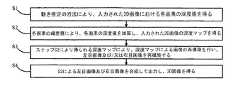
図2に示すように、その中に、Ccは入力された2D画像であり、Clは再構築された左目画像であり、Crは再構築された右目画像であり、fは目の焦点距離であり、txはベースライン距離であり、即ち、左右の目の間隔であり、Zは観察される画素の点が人の目から離れる距離であり、式(11)により算出する。Dzeroはゼロ平面の位置で、その値が[0,255]の範囲にあるが、本実施形態において、255になってもよい。式(9)(10)は、図2において、Cl、Cr、Ccにおける同一の画素の点に対応する投影の幾何学的関係である。式(9)(10)により、入力された2D画像の位置xcに対応する位置xlまたはxrの値を算出する。その後、 (xc,y)に位置する画素値を、対応する位置(xl,y)または(xr,y)にコピーする(本実施形態には位置(xl,y)にコピーする)。 As shown in FIG. 2, Cc is the input 2D image, Cl is the reconstructed left eye image, Cr is the reconstructed right eye image, and f is the focal length of the eye. Yes, tx is the baseline distance, that is, the distance between the left and right eyes, Z is the distance that the observed pixel point is away from the human eye, and is calculated by equation (11). Dzero is a position on the zero plane, and its value is in the range of [0, 255], but may be 255 in this embodiment. Expressions (9) and (10) are the geometric relationships of the projections corresponding to the same pixel points in Cl, Cr, and Cc in FIG. The value of the position xl or xr corresponding to the position xc of the input 2D image is calculated by Expressions (9) and (10). Thereafter, the pixel value located at (xc, y) is copied to the corresponding position (xl, y) or (xr, y) (in this embodiment, copied to the position (xl, y)).
即ち、ステップS3は、
以下の式により左目画像または右目画像を再構築するステップS3.1と、That is, step S3 is
Step S3.1 for reconstructing the left eye image or the right eye image according to the following formula:
(式の中に、xl、xrは、それぞれ左目画像及び右目画像において、入力された2D画像の位置xcに対応する位置であり、fは目の焦点距離であり、txは左右の目の間隔であり、Zは画素の点が人の目から離れる距離であり、Dzeroはゼロ平面の位置であり、その値は[0,255]の範囲にある。)
(xc,y)に位置する画素値を、対応する(xl,y)または(xr,y)にコピーするステップS3.2とを、さらに含む。(In the expression, xl and xr are positions corresponding to the input 2D image position xc in the left-eye image and right-eye image, f is the focal distance of the eyes, and tx is the distance between the left and right eyes, respectively. Z is the distance that the pixel point is away from the human eye, Dzero is the zero plane position, and its value is in the range [0,255].)
Step S3.2 is further included which copies the pixel value located at (xc, y) to the corresponding (xl, y) or (xr, y).
再構築された画像におけるのこぎり効果(saw teeth effect)を低減させるために、まず、入力された2D画像を水平方向にスケーリングすることで、投影する際の画像精度を向上させる。本実施形態において、水平方向に画像を元の4倍になるように引っ張って、上記した人の目の視覚関係により、行ごとのxlに対応する1/4の画像精度のx値を算出する。xlに対応するx値は画像範囲を超える場合、補間値によりxlに位置する画素値を得る。複数のxlに対応するx値は同じである場合、D(x,y)''の中の最大のxl値を採用し、他のxl位置の値は補間値により得る。xlに対応するx値は唯一である場合、xlに位置する画素値は入力された2D画像の、xに位置する画素値である。 In order to reduce the saw teeth effect in the reconstructed image, first, the input 2D image is horizontally scaled to improve the image accuracy when projecting. In this embodiment, by pulling the image in the horizontal direction to be four times the original, the x value of 1/4 image accuracy corresponding to xl for each row is calculated according to the visual relationship of the human eye described above. . When the x value corresponding to xl exceeds the image range, the pixel value located at xl is obtained by the interpolation value. When the x values corresponding to a plurality of xl are the same, the maximum xl value in D (x, y) ″ is adopted, and values at other xl positions are obtained by interpolation values. When the x value corresponding to xl is unique, the pixel value located at xl is the pixel value located at x in the input 2D image.
上記した実施形態は本発明を説明したものに過ぎず、本発明は上述した実施の形態に限定されない。当業者であれば、本発明の主旨及び範囲から逸脱しない範囲で、種々の変更や変形が可能である。そのため、あらゆる同等の技術案は本発明の範囲に属し、本発明の保護しようとする範囲は請求の範囲により決定される。 The above-described embodiments are merely descriptions of the present invention, and the present invention is not limited to the above-described embodiments. Those skilled in the art can make various changes and modifications without departing from the spirit and scope of the present invention. Therefore, all equivalent technical solutions belong to the scope of the present invention, and the scope of protection of the present invention is determined by the claims.
本発明に係る画像の運動情報に基づく2Dから3Dへの変換方法を利用して得られた画像の再構築は、画像の品質が高く、3Dの視覚効果が優れる。これによって、2Dビデオ素材を3Dに自動的に変換する市場開発を進める上で重大な意義を持っている。 The reconstruction of an image obtained by using the 2D to 3D conversion method based on the motion information of the image according to the present invention has high image quality and excellent 3D visual effects. This has significant implications for market development that automatically converts 2D video material to 3D.
本発明は2Dから3Dに変換する技術分野に関する、特に、画像運動情報に基づく2Dから3Dへの変換方法に関する。 The present invention relates to the technical field of converting 2D to 3D, and more particularly to a 2D to 3D conversion method based on image motion information.
スリーディー(Three Dimensions、3D)テレビが席巻してきて、世界のテレビ産業の新しい発展方向となり、各大手テレビメーカーは相次いで各自の3Dテレビを開発してきた。3D技術の応用は生活の中でますます人気が高まり、3D映画が絶えず制作されているが、3Dビデオ素材はまだ現在の市場ニーズを満足できない。ツーディー(Two Dimensions、2D)ビデオ素材を自動的に3Dに変換することは、新たな市場ニーズとなった。2Dから3Dへの変換は即ち2D画像内容に基づく第二画像・ビデオを作成することであり、この過程は、深度推定により深度マップ(depth map/image)を得ることと、深度マップに基づき画像を再構築する(Depth Image Based Rendering, DIBR)ことの二つの処理を含む。深度マップには8ビットのグレー値で深度情報が格納されている(グレー値0は最も遠い値であり、グレー値255は最も近い値である)。近年に、2Dから3Dへの変換の分野には、たくさんのアルゴリズムが開発され、運動推定に基づく2Dから3Dへの変換アルゴリズムがよく用いられる。この方法は、運動推定の方法により入力された画像の深度マップを得る。但し、深度マップはかなりの密度と精度を必要とするが、従来の、運動推定に基づく2Dから3Dへの変換アルゴリズムにより得られる深度マップは疎らであるため、物体を分解する時、異なる物体を区別できないので、DIBRによる画像の品質を影響する。従って、この方法が広く使用されることに制限がある。 Three Dimensions (3D) TV has swept over and became the new development direction of the global TV industry, and each major TV manufacturer has developed its own 3D TV one after another. Although the application of 3D technology is becoming more and more popular in life and 3D movies are constantly being produced, 3D video material still cannot meet the current market needs. The automatic conversion of 2D video material to 3D has become a new market need. The conversion from 2D to 3D is to create a second image / video based on the 2D image content, and this process involves obtaining a depth map / image by depth estimation and image based on the depth map. It includes two processes of reconstructing (Depth Image Based Rendering, DIBR). Depth information is stored in the depth map as 8-bit gray values (gray value 0 is the farthest value, and gray value 255 is the nearest value). In recent years, many algorithms have been developed in the field of 2D to 3D conversion, and 2D to 3D conversion algorithms based on motion estimation are often used. This method obtains a depth map of an image input by a motion estimation method. However, the depth map requires considerable density and accuracy, but the depth map obtained by the conventional 2D to 3D conversion algorithm based on motion estimation is sparse, so when disassembling objects, different objects are Since it cannot be distinguished, it affects the image quality by DIBR. Therefore, there is a limit to how widely this method can be used.
本発明は、画像運動情報に基づく2Dから3Dへの変換方法により得られる画像の品質を向上させることを目的とする。 An object of the present invention is to improve the quality of an image obtained by a 2D to 3D conversion method based on image motion information.
上記の課題を解決するために、本発明は、画像運動情報に基づく2Dから3Dへの変換方法を提供する。この方法は、
運動推定の方法により、入力された2D画像における各画素の深度値を得るステップS1と、
各画素の輝度値により、前記各画素の深度値を加算し、前記の入力された2D画像の深度マップを得るステップS2と、
ステップS2により得られる深度マップにより、深度マップによる画像の再構築を行い、左目画像及び/又は右目画像を再構築するステップS3と、
ステップS3による左目画像及び右目画像を合成して出力し、3D画像を得るステップS4と、を含む。In order to solve the above problems, the present invention provides a 2D to 3D conversion method based on image motion information. This method
Step S1 to obtain the depth value of each pixel in the input 2D image by the motion estimation method,
Step S2 to obtain the depth map of the input 2D image by adding the depth value of each pixel according to the luminance value of each pixel,
Step S3 for reconstructing the image by the depth map and reconstructing the left eye image and / or the right eye image from the depth map obtained in step S2,
The left-eye image and right-eye image by the step S3 synthesized and output, including the step S4 to obtain a 3D image.
好ましくは、ステップS1は、
運動推定の方法により、各画素の動きべクトルを算出するステップS1.1と、
ステップS1.1により得られる動きべクトルを用い、各画素の深度値を算出するステップS1.2と、をさらに含む。Preferably, step S1
Step S1.1 for calculating a motion vector of each pixel by a motion estimation method;
The method further includes step S1.2 of calculating the depth value of each pixel using the motion vector obtained in step S1.1.
好ましくは、前記深度値の計算式は以下の通りである。 Preferably, the formula for calculating the depth value is as follows.
好ましくは、前記運動推定の方法は、ダイヤモンド検索アルゴリズム(diamond search algorithm)である。 Preferably, the motion estimation method is a diamond search algorithm.
好ましくは、ステップS2は、
前記の入力された2D画像の一行目から、各画素の深度値を加算して、画素ごとの深度加算値D(x,y)'を得るステップS2.1と、
以下の式により、前記深度加算値を[0,255]の間に正規化して、正規化された深度値D(x,y)''を得るステップS2.2と、を更に含む。Preferably, step S2 includes
From the first row of the input 2D image, step S2.1 to obtain the depth addition value D (x, y) ′ for each pixel by adding the depth value of each pixel,
Further comprising step S2.2 of normalizing the depth addition value between [0,255] to obtain a normalized depth value D (x, y) '' according to the following equation.
(式の中に、I(x,y)は(x,y)に位置する画素の輝度値であり、その値は[0,255]の範囲にあり、SCALEは輝度値のスケーリング係数であり、widthは前記の入力された2D画像の幅であり、heightは前記の入力された2D画像の高さであり、DEPTH_SCALEは深度値のスケーリング係数であり、(In the equation, I (x, y) is the luminance value of the pixel located at (x, y), its value is in the range [0,255], SCALE is the luminance value scaling factor, and width Is the width of the input 2D image, height is the height of the input 2D image, DEPTH_SCALE is a depth value scaling factor,
好ましくは、ステップS2.1は、
yは0である場合、D(x,y)'=0であるが、そうではない場合、ステップS2.12へ進むステップS2.11と、
yは奇数である場合、且つxは0であると、D(x,y)'=D(x,y-1)'+D(x,y)であって、xは0ではないと、Preferably, step S2.1 includes
If y is 0, D (x, y) ′ = 0, but if not, step S2.11 proceeds to step S2.12, and
If y is an odd number and x is 0, then D (x, y) '= D (x, y-1)' + D (x, y), and x is not 0,
であるが、そうではない場合、ステップS2.13へ進むステップS2.12と、
x=width-1である場合、D(x,y)'=D(x,y-1)'+D(x,y)であるが、そうではない場合、If not, step S2.12 proceed to step S2.13; and
If x = width-1 then D (x, y) '= D (x, y-1)' + D (x, y), otherwise
であるステップS2.13と、
y<heightである場合、ステップS2.11に戻るが、そうではない場合、ステップS2.12またはS2.13によるD(x,y)'を出力するステップS2.14とを、更に含む。Step S2.13 which is
If y <height, the process returns to step S2.11. If not, step S2.14 that outputs D (x, y) ′ according to step S2.12 or S2.13 is further included.
好ましくは、SCALE=0.1である。 Preferably, SCALE = 0.1.
好ましくは、DEPTH_SCALE=120である。 Preferably, DEPTH_SCALE = 120.
好ましくは、ステップS3は、
以下の式により左目画像または右目画像を再構築するステップS3.1と、Preferably, step S3 includes
Step S3.1 for reconstructing the left eye image or the right eye image according to the following formula:
(式の中に、xl、xrは、それぞれ左目画像及び右目画像において、入力された2D画像の位置xcに対応する位置であり、fは目の焦点距離であり、txは左右の目の間隔であり、Zは画素の点が人の目から離れる距離であり、Dzeroはゼロ平面の位置で、その値が[0,255]の範囲にある。)
(xc,y)に位置する画素値を、対応する(xl,y)または(xr,y)にコピーするステップS3.2と、を更に含む。(In the expression, xl and xr are positions corresponding to the input 2D image position xc in the left-eye image and right-eye image, f is the focal distance of the eyes, and tx is the distance between the left and right eyes, respectively. Z is the distance the pixel point is away from the human eye, Dzero is the zero plane position and its value is in the range [0,255].)
a step S3.2 of copying the pixel value located at (xc, y) to the corresponding (xl, y) or (xr, y).
好ましくは、Dzero=255である。 Preferably, Dzero = 255.
本発明において、運動推定により得られた深度値に対して、加算処理を行うため、得られた深度マップは連続で且つ密であり、再構築された画像の品質及び3Dの視覚効果を向上させることができる。 In the present invention, since the addition processing is performed on the depth value obtained by motion estimation, the obtained depth map is continuous and dense, improving the quality of the reconstructed image and the 3D visual effect. be able to.
次に、図面と実施例を参考にして、本発明に係る、画像の運動情報に基づく2Dから3Dへの変換方法を詳しく説明する。 Next, a 2D to 3D conversion method based on image motion information according to the present invention will be described in detail with reference to the drawings and examples.
図1に示すように、本発明の一実施形態に係る、画像の運動情報に基づく2Dから3Dへの変換方法は、
運動推定の方法により、入力された2D画像における各画素の深度値を得るステップS1と、
各画素の輝度値により、各画素の深度値を加算し、入力された2D画像の深度マップを得るステップS2と、
ステップS2により得られる深度マップにより、深度マップによる画像の再構築を行い、左目画像及び/又は右目画像を再構築するステップS3と、
ステップS3による左目画像及び右目画像を合成して出力し、3D画像を得るステップS4とを含む。As shown in FIG. 1, according to an embodiment of the present invention, a 2D to 3D conversion method based on motion information of an image is as follows:
Step S1 to obtain the depth value of each pixel in the input 2D image by the motion estimation method,
Step S2 to obtain the depth map of the input 2D image by adding the depth value of each pixel according to the luminance value of each pixel;
Step S3 for reconstructing the image by the depth map and reconstructing the left eye image and / or the right eye image from the depth map obtained in step S2,
The left-eye image and right-eye image by the step S3 synthesized and output, and a step S4 for obtaining a 3D image.
この実施形態において、ステップS1は、
運動推定の方法により、各画素の動きべクトルを算出するステップS1.1と、
ステップS1.1により得られる動きべクトルを用い、各画素の深度値を算出するステップS1.2とをさらに含む。
ステップS1.1の中、運動推定の方法として、ダイヤモンド検索アルゴリズムが用いられ、まず、大きいダイヤモンドの検索を行い、次は小さいダイヤモンドの検索を行い、最後には、整数画素精度の動きベクトルを得る。当然ながら、ここでは、本発明の方法はこれに限定されなく、他の検索アルゴリズムも適用できる。In this embodiment, step S1 includes
Step S1.1 for calculating a motion vector of each pixel by a motion estimation method;
The method further includes step S1.2 of calculating the depth value of each pixel using the motion vector obtained in step S1.1.
In step S1.1, a diamond search algorithm is used as a motion estimation method. First, a large diamond is searched, then a small diamond is searched, and finally a motion vector with integer pixel precision is obtained. . Of course, here, the method of the present invention is not limited to this, and other search algorithms can be applied.
中には、深度値の計算式は以下の通りである。 Among them, the formula for calculating the depth value is as follows.
(式の中に、yは画素の位置する行番号であり、xは画素の位置する列番号であり、D(x,y)は未知の(x,y)に位置する画素の深度値であり、MVx及びMVyはそれぞれ上記画素の水平方向及び垂直方向における動きベクトルであり、Cは定数であり、本実施形態において、C=1である。)(In the equation, y is the row number where the pixel is located, x is the column number where the pixel is located, and D (x, y) is the depth value of the pixel located at the unknown (x, y). MVx and MVy are the motion vectors in the horizontal and vertical directions of the pixel, respectively, C is a constant, and C = 1 in this embodiment.)
ステップS1.1において検索の精度を向上させ、ノイズ(特に、ビデオ素材に加えたごま塩ノイズ)による動き検索への影響を低減させるために、ステップS1.1の動き検索を行う前に、入力された2D画像に対してノイズ除去処理を行ってもよい。これは当業者にとって周知なものであるため、ここでは贅言しない。 In order to improve the search accuracy in step S1.1 and reduce the influence of noise (especially sesame salt noise added to the video material) on the motion search, it is input before performing the motion search in step S1.1. Alternatively, noise removal processing may be performed on the 2D image. Since this is well known to those skilled in the art, it is not a luxury here.
動き検索による動きベクトルは連続ではなく、直接的に算出すると、得られる深度マップが疎らであるが、実際の深度マップが密であるはずだ。従って、本発明において、各画素の輝度値によって、動きベクトルから算出した深度値を加算する。 The motion vectors from motion search are not continuous, and when calculated directly, the resulting depth map is sparse, but the actual depth map should be dense. Therefore, in the present invention, the depth value calculated from the motion vector is added according to the luminance value of each pixel.
この実施形態において、ステップS2は、
入力された2D画像の一行目から、各画素の深度値を加算して、画素ごとの深度加算値D(x,y)'を得るステップS2.1と、
以下の式により、深度加算値を[0,255]の間に正規化して、正規化された深度値D(x,y)''を得ることで、連続で且つ密な深度マップを得るステップS2.2と、In this embodiment, step S2 includes
From the first line of the input 2D image, adding the depth value of each pixel, obtaining a depth addition value D (x, y) ′ for each pixel, step S2.1,
By obtaining the normalized depth value D (x, y) '' by normalizing the depth addition value between [0,255] by the following equation, a continuous and dense depth map is obtained in step S2. 2 and
(式の中に、I(x,y)は (x,y)に位置する画素の輝度値であり、その値は[0,255]の範囲にあり、SCALEは輝度値のスケーリング係数であり、本実施形態において、SCALE=0.1であり、widthは入力された2D画像の幅であり、heightは入力された2D画像の高さであり、DEPTH_SCALEは深度値のスケーリング係数であり、本実施形態において、DEPTH_SCALE=120であり、(In the equation, I (x, y) is the luminance value of the pixel located at (x, y), its value is in the range of [0,255], SCALE is the luminance value scaling factor, In the embodiment, SCALE = 0.1, width is the width of the input 2D image, height is the height of the input 2D image, DEPTH_SCALE is a scaling factor of the depth value, and in this embodiment, DEPTH_SCALE = 120,
である。)
ステップS2.2で得られる、正規化された深度値D(x,y)''に対して、非対称ガウスのフィルタリング処理を行い、最終の深度値D(x,y)''を得るステップS2.3とを、さらに含む。この非対称ガウスのフィルタリング処理は本分野において周知なものであるため、ここでは贅言しない。
さらに、このステップS2.1は、
yは0である場合、D(x,y)'=0であり、そうではない場合、ステップS2.12へ進むステップS2.11と、
yは奇数である場合、且つ、xは0であると、D(x,y)'=D(x,y-1)'+D(x,y)であり、xは0ではないと、It is. )
Step S2 that performs asymmetric Gaussian filtering on the normalized depth value D (x, y) '' obtained in step S2.2 to obtain the final depth value D (x, y) '' And .3. This asymmetric Gaussian filtering process is well known in the art and will not be described here.
Furthermore, this step S2.1
If y is 0, D (x, y) ′ = 0, otherwise step S2.11 proceeding to step S2.12,
If y is an odd number and x is 0, D (x, y) '= D (x, y-1)' + D (x, y), and x is not 0,
であるが、そうではない場合、ステップS2.13へ進むステップS2.12と、
x=width-1である場合、D(x,y)'=D(x,y-1)'+D(x,y)であり、そうではない場合、If not, step S2.12 proceed to step S2.13; and
If x = width-1 then D (x, y) '= D (x, y-1)' + D (x, y), otherwise
であるステップS2.13と、
y<heightである場合、ステップS2.11に戻るが、そうではない場合、ステップS2.12またはS2.13によるD(x,y)'を出力するステップS2.14とをさらに含む。Step S2.13 which is
If y <height, the process returns to step S2.11, but if not, step S2.14 that outputs D (x, y) ′ according to step S2.12 or S2.13 is further included.
画像の水平方向に投影変換を行うので、水平方向において、深度値の連続性をできるだけ保持して、動き検索によるノイズからの大きな影響を避ける。従って、本発明において、スケールモーション(Scale Motion)に水平グラデーション値を用いずに深度値を得る。 Since the projection conversion is performed in the horizontal direction of the image, the continuity of the depth value is kept as much as possible in the horizontal direction to avoid a large influence from noise due to motion search. Therefore, in the present invention, the depth value is obtained without using the horizontal gradation value for the scale motion.
人の目の視覚特性によると、視感覚が右目に頼る人は70%で、視感覚が左目に頼る人は20%である。そして、計算量を低減させるために、本発明において、DIBRにより画像を再構築する際に、一般性を失うことないように、ユーザーの頼らない目だけを再構築する。ここで、左目を黙認する。しかも、この場合、再構築されたフレームは品質が低下であるが、3Dの視覚効果に影響を与えない。従って、本実施形態におけるステップS3では、左目の画像を例として、即ち、ステップS3において、ステップS2による深度マップに基づいて、DIBRにより左目の画像を再構築する。 According to the visual characteristics of human eyes, 70% of people rely on the right eye for visual sensation and 20% rely on the left eye for visual sensation. In order to reduce the amount of calculation, in the present invention, when reconstructing an image by DIBR, only the eyes that the user does not rely on are reconstructed so as not to lose generality. Here, the left eye is acquiesced. Moreover, in this case, the reconstructed frame has a reduced quality, but does not affect the 3D visual effect. Therefore, in step S3 in the present embodiment, the left eye image is reconstructed by DIBR based on the left eye image as an example, that is, in step S3, based on the depth map in step S2.
図2に示すように、その中に、Ccは入力された2D画像であり、Clは再構築された左目画像であり、Crは再構築された右目画像であり、fは目の焦点距離であり、txはベースライン距離であり、即ち、左右の目の間隔であり、Zは観察される画素の点が人の目から離れる距離であり、式(11)により算出する。Dzeroはゼロ平面の位置で、その値が[0,255]の範囲にあるが、本実施形態において、255になってもよい。式(9)(10)は、図2において、Cl、Cr、Ccにおける同一の画素の点に対応する投影の幾何学的関係である。式(9)(10)により、入力された2D画像の位置xcに対応する位置xlまたはxrの値を算出する。その後、 (xc,y)に位置する画素値を、対応する位置(xl,y)または(xr,y)にコピーする(本実施形態には位置(xl,y)にコピーする)。 As shown in FIG. 2, Cc is the input 2D image, Cl is the reconstructed left eye image, Cr is the reconstructed right eye image, and f is the focal length of the eye. Yes, tx is the baseline distance, that is, the distance between the left and right eyes, Z is the distance that the observed pixel point is away from the human eye, and is calculated by equation (11). Dzero is a position on the zero plane, and its value is in the range of [0, 255], but may be 255 in this embodiment. Expressions (9) and (10) are the geometric relationships of the projections corresponding to the same pixel points in Cl, Cr, and Cc in FIG. The value of the position xl or xr corresponding to the position xc of the input 2D image is calculated by Expressions (9) and (10). Thereafter, the pixel value located at (xc, y) is copied to the corresponding position (xl, y) or (xr, y) (in this embodiment, copied to the position (xl, y)).
即ち、ステップS3は、
以下の式により左目画像または右目画像を再構築するステップS3.1と、That is, step S3 is
Step S3.1 for reconstructing the left eye image or the right eye image according to the following formula:
(式の中に、xl、xrは、それぞれ左目画像及び右目画像において、入力された2D画像の位置xcに対応する位置であり、fは目の焦点距離であり、txは左右の目の間隔であり、Zは画素の点が人の目から離れる距離であり、Dzeroはゼロ平面の位置であり、その値は[0,255]の範囲にある。)
(xc,y)に位置する画素値を、対応する(xl,y)または(xr,y)にコピーするステップS3.2とを、さらに含む。(In the expression, xl and xr are positions corresponding to the input 2D image position xc in the left-eye image and right-eye image, f is the focal distance of the eyes, and tx is the distance between the left and right eyes, respectively. Z is the distance that the pixel point is away from the human eye, Dzero is the zero plane position, and its value is in the range [0,255].)
Step S3.2 is further included which copies the pixel value located at (xc, y) to the corresponding (xl, y) or (xr, y).
再構築された画像におけるのこぎり効果(saw teeth effect)を低減させるために、まず、入力された2D画像を水平方向にスケーリングすることで、投影する際の画像精度を向上させる。本実施形態において、水平方向に画像を元の4倍になるように引っ張って、上記した人の目の視覚関係により、行ごとのxlに対応する1/4の画像精度のx値を算出する。xlに対応するx値は画像範囲を超える場合、補間値によりxlに位置する画素値を得る。複数のxlに対応するx値は同じである場合、D(x,y)''の中の最大のxl値を採用し、他のxl位置の値は補間値により得る。xlに対応するx値は唯一である場合、xlに位置する画素値は入力された2D画像の、xに位置する画素値である。 In order to reduce the saw teeth effect in the reconstructed image, first, the input 2D image is horizontally scaled to improve the image accuracy when projecting. In this embodiment, by pulling the image in the horizontal direction to be four times the original, the x value of 1/4 image accuracy corresponding to xl for each row is calculated according to the visual relationship of the human eye described above. . When the x value corresponding to xl exceeds the image range, the pixel value located at xl is obtained by the interpolation value. When the x values corresponding to a plurality of xl are the same, the maximum xl value in D (x, y) ″ is adopted, and values at other xl positions are obtained by interpolation values. When the x value corresponding to xl is unique, the pixel value located at xl is the pixel value located at x in the input 2D image.
上記した実施形態は本発明を説明したものに過ぎず、本発明は上述した実施の形態に限定されない。当業者であれば、本発明の主旨及び範囲から逸脱しない範囲で、種々の変更や変形が可能である。そのため、あらゆる同等の技術案は本発明の範囲に属し、本発明の保護しようとする範囲は請求の範囲により決定される。 The above-described embodiments are merely descriptions of the present invention, and the present invention is not limited to the above-described embodiments. Those skilled in the art can make various changes and modifications without departing from the spirit and scope of the present invention. Therefore, all equivalent technical solutions belong to the scope of the present invention, and the scope of protection of the present invention is determined by the claims.
本発明に係る画像の運動情報に基づく2Dから3Dへの変換方法を利用して得られた画像の再構築は、画像の品質が高く、3Dの視覚効果が優れる。これによって、2Dビデオ素材を3Dに自動的に変換する市場開発を進める上で重大な意義を持っている。 The reconstruction of an image obtained by using the 2D to 3D conversion method based on the motion information of the image according to the present invention has high image quality and excellent 3D visual effects. This has significant implications for market development that automatically converts 2D video material to 3D.
Claims (9)
Translated fromJapanese各画素の輝度値により、前記各画素の深度値を加算し、前記の入力された2D画像の深度マップを得るステップS2と、
ステップS2により得られる深度マップにより、深度マップによる画像の再構築を行い、左目画像及び/又は右目画像を再構築するステップS3と、
ステップS4による左目画像及び右目画像を合成して出力し、3D画像を得るステップS4と、を含む、ことを特徴とする画像運動情報に基づく2Dから3Dへの変換方法。Step S1 to obtain the depth value of each pixel in the input 2D image by the motion estimation method,
Step S2 to obtain the depth map of the input 2D image by adding the depth value of each pixel according to the luminance value of each pixel,
Step S3 for reconstructing the image by the depth map and reconstructing the left eye image and / or the right eye image from the depth map obtained in step S2,
A method of converting from 2D to 3D based on image motion information, comprising: combining and outputting the left eye image and right eye image in step S4 to obtain a 3D image.
運動推定の方法により、各画素の動きべクトルを算出するステップS1.1と、
S1.1により得られる動きべクトルを用い、各画素の深度値を算出するステップS1.2とをさらに含む、ことを特徴とする請求項1に記載の画像運動情報に基づく2Dから3Dへの変換方法。Step S1 is a step S1.1 of calculating a motion vector of each pixel by a motion estimation method,
2. From 2D to 3D based on image motion information according to claim 1, further comprising a step S1.2 of calculating a depth value of each pixel using a motion vector obtained by S1.1. Conversion method.
前記の入力された2D画像の一行目から、各画素の深度値を加算して、画素ごとの深度加算値D(x,y)'を得るステップS2.1と、
以下の式により、前記深度加算値を[0,255]の間に正規化して、正規化された深度値D(x,y)''を得るステップS2.2とを更に含む、ことを特徴とする請求項3に記載の画像運動情報に基づく2Dから3Dへの変換方法。
The step further includes the step S2.2 of obtaining the normalized depth value D (x, y) '' by normalizing the depth addition value between [0,255] by the following equation: The 2D to 3D conversion method based on the image motion information according to claim 3.
yは0である場合、D(x,y)'=0であるが、そうではない場合、ステップS2.12へ進むステップS2.11と、
yは奇数である場合、且つxは0であると、D(x,y)'=D(x,y-1)'+D(x,y)であって、xは0ではないと、
x=width-1である場合、D(x,y)'=D(x,y-1)'+D(x,y)であるが、そうではない場合、
y<heightである場合、ステップS2.11に戻るが、そうではない場合、ステップS2.12またはS2.13によるD(x,y)'を出力するステップS2.14とを更に含む、ことを特徴とする請求項4に記載の画像運動情報に基づく2Dから3Dへの変換方法。Step S2.1
If y is 0, D (x, y) ′ = 0, but if not, step S2.11 proceeds to step S2.12, and
If y is an odd number and x is 0, then D (x, y) '= D (x, y-1)' + D (x, y), and x is not 0,
If x = width-1 then D (x, y) '= D (x, y-1)' + D (x, y), otherwise
If y <height, return to step S2.11, otherwise, further include step S2.14 to output D (x, y) 'according to step S2.12 or S2.13. 5. The 2D to 3D conversion method based on image motion information according to claim 4.
以下の式により左目画像または右目画像を再構築するステップS3.1と、
(xc,y)に位置する画素値を、対応する位置(xl,y)または(xr,y)にコピーするステップS3.2とを更に含む、ことを特徴とする請求項5に記載の画像運動情報に基づく2Dから3Dへの変換方法。Step S3
Step S3.1 for reconstructing the left eye image or the right eye image according to the following formula:
The image according to claim 5, further comprising a step S3.2 of copying the pixel value located at (xc, y) to the corresponding position (xl, y) or (xr, y). Conversion method from 2D to 3D based on motion information.
Applications Claiming Priority (1)
| Application Number | Priority Date | Filing Date | Title |
|---|---|---|---|
| PCT/CN2011/001377WO2013023325A1 (en) | 2011-08-18 | 2011-08-18 | Method for converting 2d into 3d based on image motion information |
Publications (1)
| Publication Number | Publication Date |
|---|---|
| JP2014504468Atrue JP2014504468A (en) | 2014-02-20 |
Family
ID=47714669
Family Applications (1)
| Application Number | Title | Priority Date | Filing Date |
|---|---|---|---|
| JP2013540213APendingJP2014504468A (en) | 2011-08-18 | 2011-08-18 | 2D to 3D conversion method based on image motion information |
Country Status (5)
| Country | Link |
|---|---|
| US (1) | US20130235155A1 (en) |
| EP (1) | EP2629531A4 (en) |
| JP (1) | JP2014504468A (en) |
| CN (1) | CN103053165B (en) |
| WO (1) | WO2013023325A1 (en) |
Families Citing this family (10)
| Publication number | Priority date | Publication date | Assignee | Title |
|---|---|---|---|---|
| US9483836B2 (en)* | 2011-02-28 | 2016-11-01 | Sony Corporation | Method and apparatus for real-time conversion of 2-dimensional content to 3-dimensional content |
| KR20130033125A (en)* | 2011-09-26 | 2013-04-03 | 삼성전자주식회사 | Apparatus and method for converting 2d content into 3d content |
| CN104113745A (en) | 2013-04-17 | 2014-10-22 | 咏传电子科技(上海)有限公司 | Display device and image display method thereof |
| JP5858254B2 (en)* | 2013-06-06 | 2016-02-10 | ソニー株式会社 | Method and apparatus for real-time conversion of 2D content to 3D content |
| CN103533329B (en)* | 2013-10-09 | 2016-04-27 | 上海大学 | A kind of 2D turns the video automatic evaluation method of 3D |
| CN103826032B (en)* | 2013-11-05 | 2017-03-15 | 四川长虹电器股份有限公司 | Depth map post-processing method |
| CN105989326B (en)* | 2015-01-29 | 2020-03-03 | 北京三星通信技术研究有限公司 | Method and device for determining three-dimensional position information of human eyes |
| CN109274951B (en)* | 2017-07-13 | 2020-11-10 | 富泰华工业(深圳)有限公司 | Depth calculation method and device |
| CN111369612B (en)* | 2018-12-25 | 2023-11-24 | 北京欣奕华科技有限公司 | Three-dimensional point cloud image generation method and device |
| TWI784428B (en)* | 2021-03-03 | 2022-11-21 | 宏碁股份有限公司 | Stereo image generation method and electronic apparatus using the same |
Citations (6)
| Publication number | Priority date | Publication date | Assignee | Title |
|---|---|---|---|---|
| JPH08331607A (en)* | 1995-03-29 | 1996-12-13 | Sanyo Electric Co Ltd | Three-dimensional display image generating method |
| JP2001016609A (en)* | 1999-06-05 | 2001-01-19 | Soft Foo Deii:Kk | Stereoscopic video image generator and its method using mpeg data |
| JP2007300169A (en)* | 2006-04-27 | 2007-11-15 | Toshiba Corp | Motion vector detector |
| WO2010037512A1 (en)* | 2008-10-02 | 2010-04-08 | Fraunhofer-Gesellschaft zur Förderung der angewandten Forschung e.V. | Intermediate view synthesis and multi-view data signal extraction |
| JP2010093816A (en)* | 2008-10-09 | 2010-04-22 | Samsung Electronics Co Ltd | Apparatus and method for converting 2d image to 3d image based on visual attention |
| JP2010239177A (en)* | 2009-03-30 | 2010-10-21 | Toppan Printing Co Ltd | Image generation method |
Family Cites Families (10)
| Publication number | Priority date | Publication date | Assignee | Title |
|---|---|---|---|---|
| JP2001103513A (en)* | 1999-09-27 | 2001-04-13 | Sanyo Electric Co Ltd | Method for converting two-dimensional video image into three-dimensional video image |
| US8036451B2 (en)* | 2004-02-17 | 2011-10-11 | Koninklijke Philips Electronics N.V. | Creating a depth map |
| CN101720480B (en)* | 2007-07-03 | 2012-07-18 | 皇家飞利浦电子股份有限公司 | Computing a depth map |
| CN101271578B (en)* | 2008-04-10 | 2010-06-02 | 清华大学 | A Depth Sequence Generation Method in Plane Video to Stereo Video Technology |
| KR20100002032A (en)* | 2008-06-24 | 2010-01-06 | 삼성전자주식회사 | Image generating method, image processing method, and apparatus thereof |
| KR20100135032A (en)* | 2009-06-16 | 2010-12-24 | 삼성전자주식회사 | 3D image conversion device and method of 2D image |
| TWI564843B (en)* | 2009-07-01 | 2017-01-01 | 晨星半導體股份有限公司 | Motion estimation method and motion estimation apparatus thereof |
| CN101631256B (en)* | 2009-08-13 | 2011-02-09 | 浙江大学 | Method for converting 2D video to 3D video in 3D television system |
| US8610758B2 (en)* | 2009-12-15 | 2013-12-17 | Himax Technologies Limited | Depth map generation for a video conversion system |
| CN102075780B (en)* | 2011-02-25 | 2014-02-26 | 福建华映显示科技有限公司 | Stereoscopic image generating device and method |
- 2011
- 2011-08-18JPJP2013540213Apatent/JP2014504468A/enactivePending
- 2011-08-18CNCN201180028889.9Apatent/CN103053165B/enactiveActive
- 2011-08-18EPEP11870997.1Apatent/EP2629531A4/ennot_activeWithdrawn
- 2011-08-18USUS13/818,101patent/US20130235155A1/ennot_activeAbandoned
- 2011-08-18WOPCT/CN2011/001377patent/WO2013023325A1/enactiveApplication Filing
Patent Citations (7)
| Publication number | Priority date | Publication date | Assignee | Title |
|---|---|---|---|---|
| JPH08331607A (en)* | 1995-03-29 | 1996-12-13 | Sanyo Electric Co Ltd | Three-dimensional display image generating method |
| JP2001016609A (en)* | 1999-06-05 | 2001-01-19 | Soft Foo Deii:Kk | Stereoscopic video image generator and its method using mpeg data |
| JP2007300169A (en)* | 2006-04-27 | 2007-11-15 | Toshiba Corp | Motion vector detector |
| WO2010037512A1 (en)* | 2008-10-02 | 2010-04-08 | Fraunhofer-Gesellschaft zur Förderung der angewandten Forschung e.V. | Intermediate view synthesis and multi-view data signal extraction |
| JP2012504805A (en)* | 2008-10-02 | 2012-02-23 | フラウンホッファー−ゲゼルシャフト ツァ フェルダールング デァ アンゲヴァンテン フォアシュンク エー.ファオ | Intermediate image synthesis and multi-view data signal extraction |
| JP2010093816A (en)* | 2008-10-09 | 2010-04-22 | Samsung Electronics Co Ltd | Apparatus and method for converting 2d image to 3d image based on visual attention |
| JP2010239177A (en)* | 2009-03-30 | 2010-10-21 | Toppan Printing Co Ltd | Image generation method |
Also Published As
| Publication number | Publication date |
|---|---|
| US20130235155A1 (en) | 2013-09-12 |
| CN103053165A (en) | 2013-04-17 |
| WO2013023325A1 (en) | 2013-02-21 |
| EP2629531A4 (en) | 2015-01-21 |
| EP2629531A1 (en) | 2013-08-21 |
| CN103053165B (en) | 2015-02-11 |
Similar Documents
| Publication | Publication Date | Title |
|---|---|---|
| JP2014504468A (en) | 2D to 3D conversion method based on image motion information | |
| JP7403528B2 (en) | Method and system for reconstructing color and depth information of a scene | |
| JP5153940B2 (en) | System and method for image depth extraction using motion compensation | |
| JP5818514B2 (en) | Image processing apparatus, image processing method, and program | |
| US9401039B2 (en) | Image processing device, image processing method, program, and integrated circuit | |
| JP5665135B2 (en) | Image display device, image generation device, image display method, image generation method, and program | |
| CN105144234A (en) | Generate a depth map for an input image using an example approximate depth map associated with an example similar image | |
| CN107578430B (en) | Stereo matching method based on self-adaptive weight and local entropy | |
| WO2011033673A1 (en) | Image processing apparatus | |
| JP5473173B2 (en) | Image processing apparatus, image processing method, and image processing program | |
| CN101873508B (en) | Intermediate view synthesis method based on improved BP (Belief Propagation) algorithm | |
| JP2013143702A (en) | Virtual viewpoint image generation device, virtual viewpoint image generation method, control program, recording medium, and stereoscopic display device | |
| JP5691965B2 (en) | Depth estimation data generation apparatus, generation method and generation program, and pseudo stereoscopic image generation apparatus, generation method and generation program | |
| JP5692051B2 (en) | Depth estimation data generation apparatus, generation method and generation program, and pseudo stereoscopic image generation apparatus, generation method and generation program | |
| JP5210416B2 (en) | Stereoscopic image generating apparatus, stereoscopic image generating method, program, and recording medium | |
| US20130187907A1 (en) | Image processing apparatus, image processing method, and program | |
| JP5304758B2 (en) | Multi-viewpoint image creation apparatus, multi-viewpoint image creation method, and multi-viewpoint image display system | |
| CN114640885A (en) | Video frame insertion method, training method, device and electronic equipment | |
| JP5627498B2 (en) | Stereo image generating apparatus and method | |
| JP5464129B2 (en) | Image processing apparatus and parallax information generating apparatus | |
| CN118447143A (en) | Three-dimensional model reconstruction method, device, medium and computer equipment | |
| CN103200417B (en) | 2D (Two Dimensional) to 3D (Three Dimensional) conversion method | |
| CN107610070B (en) | Free stereo matching method based on three-camera collection | |
| JP2013513172A (en) | Modeling concave surfaces in image-based visual hulls | |
| KR20150037203A (en) | Device for correcting depth map of three dimensional image and method for correcting the same |
Legal Events
| Date | Code | Title | Description |
|---|---|---|---|
| A977 | Report on retrieval | Free format text:JAPANESE INTERMEDIATE CODE: A971007 Effective date:20140625 | |
| A131 | Notification of reasons for refusal | Free format text:JAPANESE INTERMEDIATE CODE: A131 Effective date:20140708 | |
| A02 | Decision of refusal | Free format text:JAPANESE INTERMEDIATE CODE: A02 Effective date:20141209 |