JP2014502528A - Method and apparatus for accurately tracking charge available in a transdermal energy transmission system - Google Patents
Method and apparatus for accurately tracking charge available in a transdermal energy transmission systemDownload PDFInfo
- Publication number
- JP2014502528A JP2014502528AJP2013544821AJP2013544821AJP2014502528AJP 2014502528 AJP2014502528 AJP 2014502528AJP 2013544821 AJP2013544821 AJP 2013544821AJP 2013544821 AJP2013544821 AJP 2013544821AJP 2014502528 AJP2014502528 AJP 2014502528A
- Authority
- JP
- Japan
- Prior art keywords
- remaining time
- battery pack
- user
- charge
- implantable
- Prior art date
- Legal status (The legal status is an assumption and is not a legal conclusion. Google has not performed a legal analysis and makes no representation as to the accuracy of the status listed.)
- Pending
Links
Images


Classifications
- H—ELECTRICITY
- H02—GENERATION; CONVERSION OR DISTRIBUTION OF ELECTRIC POWER
- H02J—CIRCUIT ARRANGEMENTS OR SYSTEMS FOR SUPPLYING OR DISTRIBUTING ELECTRIC POWER; SYSTEMS FOR STORING ELECTRIC ENERGY
- H02J7/00—Circuit arrangements for charging or depolarising batteries or for supplying loads from batteries
- H02J7/0047—Circuit arrangements for charging or depolarising batteries or for supplying loads from batteries with monitoring or indicating devices or circuits
- A—HUMAN NECESSITIES
- A61—MEDICAL OR VETERINARY SCIENCE; HYGIENE
- A61M—DEVICES FOR INTRODUCING MEDIA INTO, OR ONTO, THE BODY; DEVICES FOR TRANSDUCING BODY MEDIA OR FOR TAKING MEDIA FROM THE BODY; DEVICES FOR PRODUCING OR ENDING SLEEP OR STUPOR
- A61M60/00—Blood pumps; Devices for mechanical circulatory actuation; Balloon pumps for circulatory assistance
- A61M60/10—Location thereof with respect to the patient's body
- A61M60/122—Implantable pumps or pumping devices, i.e. the blood being pumped inside the patient's body
- A61M60/126—Implantable pumps or pumping devices, i.e. the blood being pumped inside the patient's body implantable via, into, inside, in line, branching on, or around a blood vessel
- A61M60/148—Implantable pumps or pumping devices, i.e. the blood being pumped inside the patient's body implantable via, into, inside, in line, branching on, or around a blood vessel in line with a blood vessel using resection or like techniques, e.g. permanent endovascular heart assist devices
- A—HUMAN NECESSITIES
- A61—MEDICAL OR VETERINARY SCIENCE; HYGIENE
- A61M—DEVICES FOR INTRODUCING MEDIA INTO, OR ONTO, THE BODY; DEVICES FOR TRANSDUCING BODY MEDIA OR FOR TAKING MEDIA FROM THE BODY; DEVICES FOR PRODUCING OR ENDING SLEEP OR STUPOR
- A61M60/00—Blood pumps; Devices for mechanical circulatory actuation; Balloon pumps for circulatory assistance
- A61M60/10—Location thereof with respect to the patient's body
- A61M60/122—Implantable pumps or pumping devices, i.e. the blood being pumped inside the patient's body
- A61M60/165—Implantable pumps or pumping devices, i.e. the blood being pumped inside the patient's body implantable in, on, or around the heart
- A61M60/178—Implantable pumps or pumping devices, i.e. the blood being pumped inside the patient's body implantable in, on, or around the heart drawing blood from a ventricle and returning the blood to the arterial system via a cannula external to the ventricle, e.g. left or right ventricular assist devices
- A—HUMAN NECESSITIES
- A61—MEDICAL OR VETERINARY SCIENCE; HYGIENE
- A61M—DEVICES FOR INTRODUCING MEDIA INTO, OR ONTO, THE BODY; DEVICES FOR TRANSDUCING BODY MEDIA OR FOR TAKING MEDIA FROM THE BODY; DEVICES FOR PRODUCING OR ENDING SLEEP OR STUPOR
- A61M60/00—Blood pumps; Devices for mechanical circulatory actuation; Balloon pumps for circulatory assistance
- A61M60/20—Type thereof
- A61M60/205—Non-positive displacement blood pumps
- A61M60/216—Non-positive displacement blood pumps including a rotating member acting on the blood, e.g. impeller
- A—HUMAN NECESSITIES
- A61—MEDICAL OR VETERINARY SCIENCE; HYGIENE
- A61M—DEVICES FOR INTRODUCING MEDIA INTO, OR ONTO, THE BODY; DEVICES FOR TRANSDUCING BODY MEDIA OR FOR TAKING MEDIA FROM THE BODY; DEVICES FOR PRODUCING OR ENDING SLEEP OR STUPOR
- A61M60/00—Blood pumps; Devices for mechanical circulatory actuation; Balloon pumps for circulatory assistance
- A61M60/50—Details relating to control
- A61M60/508—Electronic control means, e.g. for feedback regulation
- A61M60/538—Regulation using real-time blood pump operational parameter data, e.g. motor current
- A—HUMAN NECESSITIES
- A61—MEDICAL OR VETERINARY SCIENCE; HYGIENE
- A61M—DEVICES FOR INTRODUCING MEDIA INTO, OR ONTO, THE BODY; DEVICES FOR TRANSDUCING BODY MEDIA OR FOR TAKING MEDIA FROM THE BODY; DEVICES FOR PRODUCING OR ENDING SLEEP OR STUPOR
- A61M60/00—Blood pumps; Devices for mechanical circulatory actuation; Balloon pumps for circulatory assistance
- A61M60/50—Details relating to control
- A61M60/585—User interfaces
- A—HUMAN NECESSITIES
- A61—MEDICAL OR VETERINARY SCIENCE; HYGIENE
- A61M—DEVICES FOR INTRODUCING MEDIA INTO, OR ONTO, THE BODY; DEVICES FOR TRANSDUCING BODY MEDIA OR FOR TAKING MEDIA FROM THE BODY; DEVICES FOR PRODUCING OR ENDING SLEEP OR STUPOR
- A61M60/00—Blood pumps; Devices for mechanical circulatory actuation; Balloon pumps for circulatory assistance
- A61M60/80—Constructional details other than related to driving
- A61M60/855—Constructional details other than related to driving of implantable pumps or pumping devices
- A61M60/871—Energy supply devices; Converters therefor
- A61M60/873—Energy supply devices; Converters therefor specially adapted for wireless or transcutaneous energy transfer [TET], e.g. inductive charging
- A—HUMAN NECESSITIES
- A61—MEDICAL OR VETERINARY SCIENCE; HYGIENE
- A61M—DEVICES FOR INTRODUCING MEDIA INTO, OR ONTO, THE BODY; DEVICES FOR TRANSDUCING BODY MEDIA OR FOR TAKING MEDIA FROM THE BODY; DEVICES FOR PRODUCING OR ENDING SLEEP OR STUPOR
- A61M60/00—Blood pumps; Devices for mechanical circulatory actuation; Balloon pumps for circulatory assistance
- A61M60/80—Constructional details other than related to driving
- A61M60/855—Constructional details other than related to driving of implantable pumps or pumping devices
- A61M60/871—Energy supply devices; Converters therefor
- A61M60/876—Implantable batteries
- A—HUMAN NECESSITIES
- A61—MEDICAL OR VETERINARY SCIENCE; HYGIENE
- A61M—DEVICES FOR INTRODUCING MEDIA INTO, OR ONTO, THE BODY; DEVICES FOR TRANSDUCING BODY MEDIA OR FOR TAKING MEDIA FROM THE BODY; DEVICES FOR PRODUCING OR ENDING SLEEP OR STUPOR
- A61M2205/00—General characteristics of the apparatus
- A61M2205/17—General characteristics of the apparatus with redundant control systems
- A—HUMAN NECESSITIES
- A61—MEDICAL OR VETERINARY SCIENCE; HYGIENE
- A61M—DEVICES FOR INTRODUCING MEDIA INTO, OR ONTO, THE BODY; DEVICES FOR TRANSDUCING BODY MEDIA OR FOR TAKING MEDIA FROM THE BODY; DEVICES FOR PRODUCING OR ENDING SLEEP OR STUPOR
- A61M2205/00—General characteristics of the apparatus
- A61M2205/18—General characteristics of the apparatus with alarm
- A—HUMAN NECESSITIES
- A61—MEDICAL OR VETERINARY SCIENCE; HYGIENE
- A61M—DEVICES FOR INTRODUCING MEDIA INTO, OR ONTO, THE BODY; DEVICES FOR TRANSDUCING BODY MEDIA OR FOR TAKING MEDIA FROM THE BODY; DEVICES FOR PRODUCING OR ENDING SLEEP OR STUPOR
- A61M2205/00—General characteristics of the apparatus
- A61M2205/35—Communication
- A61M2205/3507—Communication with implanted devices, e.g. external control
- A61M2205/3523—Communication with implanted devices, e.g. external control using telemetric means
- A—HUMAN NECESSITIES
- A61—MEDICAL OR VETERINARY SCIENCE; HYGIENE
- A61M—DEVICES FOR INTRODUCING MEDIA INTO, OR ONTO, THE BODY; DEVICES FOR TRANSDUCING BODY MEDIA OR FOR TAKING MEDIA FROM THE BODY; DEVICES FOR PRODUCING OR ENDING SLEEP OR STUPOR
- A61M2205/00—General characteristics of the apparatus
- A61M2205/50—General characteristics of the apparatus with microprocessors or computers
- A—HUMAN NECESSITIES
- A61—MEDICAL OR VETERINARY SCIENCE; HYGIENE
- A61M—DEVICES FOR INTRODUCING MEDIA INTO, OR ONTO, THE BODY; DEVICES FOR TRANSDUCING BODY MEDIA OR FOR TAKING MEDIA FROM THE BODY; DEVICES FOR PRODUCING OR ENDING SLEEP OR STUPOR
- A61M2205/00—General characteristics of the apparatus
- A61M2205/82—Internal energy supply devices
- A61M2205/8206—Internal energy supply devices battery-operated
- A—HUMAN NECESSITIES
- A61—MEDICAL OR VETERINARY SCIENCE; HYGIENE
- A61M—DEVICES FOR INTRODUCING MEDIA INTO, OR ONTO, THE BODY; DEVICES FOR TRANSDUCING BODY MEDIA OR FOR TAKING MEDIA FROM THE BODY; DEVICES FOR PRODUCING OR ENDING SLEEP OR STUPOR
- A61M2205/00—General characteristics of the apparatus
- A61M2205/82—Internal energy supply devices
- A61M2205/8237—Charging means
- A61M2205/8243—Charging means by induction
- H—ELECTRICITY
- H02—GENERATION; CONVERSION OR DISTRIBUTION OF ELECTRIC POWER
- H02J—CIRCUIT ARRANGEMENTS OR SYSTEMS FOR SUPPLYING OR DISTRIBUTING ELECTRIC POWER; SYSTEMS FOR STORING ELECTRIC ENERGY
- H02J2310/00—The network for supplying or distributing electric power characterised by its spatial reach or by the load
- H02J2310/10—The network having a local or delimited stationary reach
- H02J2310/20—The network being internal to a load
- H02J2310/23—The load being a medical device, a medical implant, or a life supporting device
- H—ELECTRICITY
- H02—GENERATION; CONVERSION OR DISTRIBUTION OF ELECTRIC POWER
- H02J—CIRCUIT ARRANGEMENTS OR SYSTEMS FOR SUPPLYING OR DISTRIBUTING ELECTRIC POWER; SYSTEMS FOR STORING ELECTRIC ENERGY
- H02J7/00—Circuit arrangements for charging or depolarising batteries or for supplying loads from batteries
- H02J7/0047—Circuit arrangements for charging or depolarising batteries or for supplying loads from batteries with monitoring or indicating devices or circuits
- H02J7/0048—Detection of remaining charge capacity or state of charge [SOC]
Landscapes
- Health & Medical Sciences (AREA)
- Engineering & Computer Science (AREA)
- Heart & Thoracic Surgery (AREA)
- Cardiology (AREA)
- Animal Behavior & Ethology (AREA)
- General Health & Medical Sciences (AREA)
- Anesthesiology (AREA)
- Biomedical Technology (AREA)
- Hematology (AREA)
- Life Sciences & Earth Sciences (AREA)
- Veterinary Medicine (AREA)
- Mechanical Engineering (AREA)
- Public Health (AREA)
- Vascular Medicine (AREA)
- Computer Networks & Wireless Communication (AREA)
- Power Engineering (AREA)
- Human Computer Interaction (AREA)
- Charge And Discharge Circuits For Batteries Or The Like (AREA)
- Measurement Of The Respiration, Hearing Ability, Form, And Blood Characteristics Of Living Organisms (AREA)
- Electrotherapy Devices (AREA)
Abstract
Translated fromJapaneseDescription
Translated fromJapanese本願は、2010年12月20日に出願し、米国仮特許出願第61/425,162号の、「経皮エネルギー伝送システムにおいて使用可能な充電を正確に追跡するための方法および装置」の出願の優先権を主張する。 This application is filed on December 20, 2010 and is filed in US Provisional Patent Application No. 61 / 425,162, “Method and Apparatus for Accurately Tracking Charges Usable in Transcutaneous Energy Transmission Systems”. Claim priority.
本発明は、経皮エネルギー伝送(TET)システムに関するものであり、とくに、TETシステムにおいて電池充電を正確に追跡し患者に正確な電池駆動時間を提供するための改善された装置および方法に関するものである。 The present invention relates to transcutaneous energy transfer (TET) systems, and more particularly, to an improved apparatus and method for accurately tracking battery charging and providing accurate battery life to a patient in a TET system. is there.
埋め込み用に構成された多くの医療装置は高電力要件を有し、外部電力源に頻繁に接続しなければならない。これらの高電力埋め込み可能装置に接続して用いられる、誘導的に接続した経皮エネルギー伝送(TET)システムはますます普及してきている。TETシステムを用い、再充電可能な電池のような埋め込まれた電源を補充、交換、または充電することができる。他のタイプの電力伝送システムとは異なり、TETシステムは、皮膚に穴をあけることなく、埋め込まれた電気装置および/または機械装置に電力を提供する、または内部電源を再充電することができるという利点を有する。よって、感染の可能性が低減し、快適さと便利さが向上する。 Many medical devices configured for implantation have high power requirements and must be frequently connected to an external power source. Inductively connected transcutaneous energy transfer (TET) systems used in connection with these high power implantable devices are becoming increasingly popular. A TET system can be used to replenish, replace, or charge an embedded power source such as a rechargeable battery. Unlike other types of power transfer systems, TET systems can provide power to embedded electrical and / or mechanical devices or recharge internal power supplies without puncturing the skin. Have advantages. Thus, the possibility of infection is reduced and comfort and convenience are improved.
TET装置は、組織の層をはさむことにより離れた、外部の一次コイルおよび埋め込まれた二次コイルを備える。一次コイルは、一般的に直流電流に変換して埋め込まれた装置に電力を供給するため、皮下の二次コイルにおいて交流電流を誘導するように設計される。TET装置は従って一般的には、一次コイルに適切な交流電流を提供するためのオシレータおよび他の電気回路も備える。これらの回路は一般的には電力を外部電源から受ける。 The TET device comprises an external primary coil and an embedded secondary coil that are separated by sandwiching a layer of tissue. The primary coil is typically designed to induce an alternating current in the subcutaneous secondary coil to convert it to a direct current and power the implanted device. TET devices therefore generally also include an oscillator and other electrical circuitry for providing a suitable alternating current to the primary coil. These circuits generally receive power from an external power source.
TETシステムは一般に、外部電源が使用可能でない場合に、いずれかの埋め込まれた装置に電力を供給するのに用いることができる、埋め込まれた再充電可能な電池パックを備える。しかしながら、外部電源から切断された際、患者は内部電池パックが充電サイクルを要するまでどれだけ持続するかわからない場合が多い。残り充電を計算するための従来技術の方法は、実際の残り充電ではなく、電池電圧に基づく。電池電圧は充電に対して線形ではないので、これらの方法は時間とともに線形的減少を報告するのではなく、長時間ほぼ完全充電を報告した後すぐに完全消耗となり得る。この電池充電の誤解を招く表示は、生存を埋め込まれたTETシステムに依存し、外部電力または充電源にすぐに再接続することができない場合があり得る患者にとって、極めて危険であり得る。 A TET system generally comprises an embedded rechargeable battery pack that can be used to power any embedded device when an external power source is not available. However, when disconnected from an external power source, the patient often does not know how long the internal battery pack will last until it takes a charge cycle. Prior art methods for calculating remaining charge are based on battery voltage, not actual remaining charge. Since battery voltage is not linear with respect to charging, these methods do not report a linear decrease over time, but can become fully depleted immediately after reporting almost full charge for an extended period of time. This misleading indication of battery charging can be extremely dangerous for patients who rely on an embedded TET system for survival and may not be able to immediately reconnect to external power or a charging source.
従来のシステムの上記の欠点および他の欠点を克服するため、本発明は、経皮エネルギー伝送(TET)システムにおいて、電池パックまたは充電貯蔵装置の充電および放電を追跡するための改善された方法および装置を提供する。 In order to overcome the above and other shortcomings of conventional systems, the present invention provides an improved method for tracking the charging and discharging of a battery pack or charge storage device in a transcutaneous energy transfer (TET) system and Providing equipment.
本発明の第1態様は、電池パックに残る最新の充電を割り出し、心臓補助装置の最新の電力消費速度を測定するステップと、電池パックのエネルギーレベルが測定された電力消費速度で所定の閾値レベルを下回るまでの残り時間を割り出すステップと、電池パックの消耗までの残り時間を使用者に伝達するステップとを含む、経皮エネルギー伝送システムにおいて電力消費および電力補充を追跡する方法を提供する。 The first aspect of the present invention includes the step of determining the latest charge remaining in the battery pack and measuring the latest power consumption rate of the cardiac assist device; A method of tracking power consumption and power replenishment in a transdermal energy transmission system is provided that includes determining a remaining time until the battery pack is less than and communicating a remaining time until the battery pack is exhausted to a user.
1つの実施形態では、これらのステップを繰り返し行って、使用者に報告される残り時間を更新する。 In one embodiment, these steps are repeated to update the remaining time reported to the user.
特定の実施形態では、残り時間は外部ディスプレイによって使用者に伝達することができるが、他の実施形態では、振動信号または聴覚信号を用いて、電池パックの消耗までの残り時間を伝達する。 In certain embodiments, the remaining time can be communicated to the user by an external display, while in other embodiments, a vibration signal or an audible signal is used to communicate the remaining time until battery pack depletion.
本発明の第2態様は、心臓補助装置、再充電可能な電池パック、および制御装置を備える埋め込み可能な装置を提供する。制御装置は心臓補助装置および再充電可能な電池パックに接続する。制御装置は電池パックの充電レベルおよび心臓補助装置の電力消費速度を測定するように構成される。制御装置はさらに、電池パックの充電レベルが所定の閾値レベルに達するまでの残り時間を計算し、その時間を使用者に伝達するように構成される。 A second aspect of the present invention provides an implantable device comprising a cardiac assist device, a rechargeable battery pack, and a control device. The control device connects to the cardiac assist device and the rechargeable battery pack. The controller is configured to measure the charge level of the battery pack and the power consumption rate of the cardiac assist device. The controller is further configured to calculate a remaining time until the charge level of the battery pack reaches a predetermined threshold level and communicate the time to the user.
1つの実施形態では、制御装置はさらに電池充電レベルおよび電力消費速度を繰り返し測定し、更新された残り時間を使用者に継続的に伝達するように構成される。制御装置は履歴負荷監視および残り電池容量に基づき残り電池時間を予測することができる。 In one embodiment, the controller is further configured to repeatedly measure the battery charge level and the power consumption rate and continuously communicate the updated remaining time to the user. The controller can predict remaining battery time based on historical load monitoring and remaining battery capacity.
特定の実施形態では、制御装置は残り時間を外部ディスプレイによって使用者に伝達する。他の実施形態では、制御装置は振動信号または聴覚信号を用いて、残り時間を使用者に伝達することができる。 In certain embodiments, the controller communicates the remaining time to the user via an external display. In other embodiments, the controller can communicate the remaining time to the user using vibration signals or auditory signals.
本発明は添付の図面に関連する以下の詳細な説明からより完全に理解されるだろう。ここで特定の典型的な実施形態について記載し、本明細書に開示する方法および装置の原理の全体的な理解を提供する。これらの実施形態の1つ以上の例を添付の図面に示す。当業者であれば、本明細書に具体的に記載し添付の図面に示す方法および装置が、非限定的な典型的な実施形態であり、本発明の範囲が特許請求の範囲によってのみ定義されることを理解するだろう。1つの典型的な実施形態に関して示される、または記載される特徴は他の実施形態の特徴と組み合わせてもよい。こうした変更および変形は本発明の範囲内に含まれることを意図する。 The invention will be more fully understood from the following detailed description taken in conjunction with the accompanying drawings, in which: Certain exemplary embodiments will now be described to provide an overall understanding of the principles of the methods and apparatus disclosed herein. One or more examples of these embodiments are illustrated in the accompanying drawings. Those skilled in the art will appreciate that the methods and apparatus specifically described herein and shown in the accompanying drawings are exemplary, non-limiting embodiments, and the scope of the present invention is defined only by the claims. You will understand that. The features shown or described with respect to one exemplary embodiment may be combined with the features of other embodiments. Such modifications and variations are intended to be included within the scope of the present invention.
経皮エネルギー伝送(TET)システムは、一次コイルを二次コイルに誘導的に接続することにより作動する。患者の体外へ配置するために構成された一次コイルは電源に接続され、当該一次コイルは時変磁場を生成する。一次コイルを二次コイルと適切に位置調整すると、一次コイルからの時変磁場が二次コイルにおいて交流電流を誘導する。二次コイルは患者の体内への埋め込み用に構成され、電流を配線しこれを用い、例えば、電池パックを充電する、または心室補助装置(VAD)、心臓補助装置、または他の埋め込み可能な装置のような埋め込み可能な装置に電力を供給する制御装置に接続することができる。誘導を用いてエネルギーを伝送することにより、TETシステムは、埋め込み可能な装置に電力を供給するのに患者の皮膚を貫通した開放通路を維持する必要を回避する。 Transcutaneous energy transfer (TET) systems operate by inductively connecting a primary coil to a secondary coil. A primary coil configured for placement outside the patient's body is connected to a power source, and the primary coil generates a time-varying magnetic field. When the primary coil is properly aligned with the secondary coil, the time-varying magnetic field from the primary coil induces an alternating current in the secondary coil. The secondary coil is configured for implantation into the patient's body and routes and uses current to charge, for example, a battery pack, or ventricular assist device (VAD), cardiac assist device, or other implantable device Can be connected to a controller that provides power to the implantable device. By using induction to transmit energy, the TET system avoids the need to maintain an open passage through the patient's skin to power the implantable device.
TETシステムは、患者が外部の一次コイルおよび電源との接続を切断していくらかの時間を過ごすことを可能にする、埋め込まれた再充電可能な電池パックを備える。再充電可能な電池パックに接続した制御装置は、その充電を測定し、残り駆動時間に基づき、電池がほぼ消耗し尽くしている場合に患者に警告するように構成される。 The TET system includes an embedded rechargeable battery pack that allows the patient to spend some time disconnecting from the external primary coil and power source. A controller connected to the rechargeable battery pack is configured to measure the charge and warn the patient when the battery is almost exhausted based on the remaining drive time.
従来技術の方法および装置は、残り充電を電池パックの電圧のみに基づき割り出す。しかしながら、電池電圧と残り充電との間の関係は線形ではないため、これは誤解を招き得る。結果として、電池は予想される時間より長く完全充電を報告する場合があり得る。さらに悪いことには、電池の測定電圧が低下し始めた後、完全消耗の状態まで急速に低下する場合があり得る。これは埋め込まれたTETシステムを有する患者にとって極めて危険である。多くの場合、彼らの意識および生存が、電池パックおよび接続された心臓補助装置の作動に依存しているためである。 Prior art methods and devices determine the remaining charge based solely on battery pack voltage. However, this can be misleading because the relationship between battery voltage and remaining charge is not linear. As a result, the battery may report a full charge longer than expected. To make matters worse, after the measured voltage of the battery begins to drop, it can drop rapidly to a fully exhausted state. This is extremely dangerous for patients with an implanted TET system. In many cases, their consciousness and survival depends on the operation of the battery pack and the connected cardiac assist device.
本発明は、電池パックの残り充電および接続された心臓補助装置の電力消費速度を測定し、電池パックの充電レベルが測定消費速度で所定の閾値レベルに達するまでの残り時間を計算し、残り時間を使用者に伝達するTETシステムにおいて電力消費を追跡する埋め込み可能な装置および方法を提供することにより、これらの問題を解決する。この方法は充電サイクルが必要になるまでの残り時間のより正確な表示を使用者に提供する。これは、従って、外部電力供給を必要としない時間の、より信頼できる推定値を提供することにより、患者の生活の質を向上させる。 The present invention measures the remaining charge of the battery pack and the power consumption rate of the connected cardiac assist device, calculates the remaining time until the charge level of the battery pack reaches a predetermined threshold level at the measured consumption rate, These problems are solved by providing an implantable device and method for tracking power consumption in a TET system that communicates to a user. This method provides the user with a more accurate indication of the time remaining until a charge cycle is required. This therefore improves the patient's quality of life by providing a more reliable estimate of the time when no external power supply is required.
図1は、本発明の典型的なTETシステムの図を示す。埋め込み可能な装置は、患者の体内への配置用に構成された、複数の二次コイル100、または単一の二次コイルを備える。二次コイルは、使用または貯蔵のため、単一または複数の二次コイルから電流を受けるように構成された制御装置102に接続される。制御装置は次に、電流が、例えば、(制御装置102と一体化させることができる)電池を充電するまたは心室補助装置104もしくは他の埋め込み可能な装置に電力を供給するように、指示することができる。 FIG. 1 shows a diagram of an exemplary TET system of the present invention. The implantable device comprises a plurality of secondary coils 100, or a single secondary coil, configured for placement within a patient's body. The secondary coil is connected to a controller 102 that is configured to receive current from a single or multiple secondary coils for use or storage. The controller then directs the current to charge, for example, a battery (which can be integrated with the controller 102) or power the
図1は、体外に残り、二次コイルにエネルギーを誘導的に伝送するように構成された、一次コイル106の典型的な実施形態も示す。一次コイル106は外部電源に接続し、当該外部電源は、例えば調整および制御回路を備えることができる。任意で、2つ以上の一次コイル106を多数の二次コイル100と同時に用いて、埋め込まれた電池を充電するのに必要な時間を低減することができる。 FIG. 1 also shows an exemplary embodiment of a primary coil 106 that remains outside the body and is configured to inductively transfer energy to a secondary coil. The primary coil 106 is connected to an external power source, which can include, for example, a regulation and control circuit. Optionally, two or more primary coils 106 can be used simultaneously with multiple secondary coils 100 to reduce the time required to charge the embedded battery.
使用時に、一次コイル106と二次コイル100とが実質的に軸方向に位置合わせされるように、一次コイル106は二次コイル100の領域の上に配置される。電源108を次に作動し、一次コイル106において時変磁場を生成する。電源108は所望の出力電圧および電流プロファイルを生成する調整回路を備えることができる。時変磁場は二次コイル100において電流を誘導し、電流はその後、制御装置102および接続されたいずれかの心室補助装置104または充電貯蔵装置に分配される。 In use, primary coil 106 is positioned over the area of secondary coil 100 such that primary coil 106 and secondary coil 100 are substantially axially aligned. The power supply 108 is then activated to generate a time varying magnetic field in the primary coil 106. The power supply 108 can include a regulator circuit that generates a desired output voltage and current profile. The time-varying magnetic field induces a current in the secondary coil 100 that is then distributed to the controller 102 and any connected ventricular assist
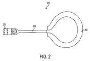
図2は、患者の体内への配置用に構成された典型的な二次コイル200を示す。二次コイル200は、数巻きの導電線で構成されるコイル部202、接続部204、および任意のインターフェース部206を特徴とする。コイル部202は、意図する埋め込み部位のような多数の要因に応じて、大きさおよび電線の巻き数が異なり得る。典型的な実施形態では、コイル部202は、直径2インチのコイルに12回巻きのリッツ線を備える。電線に加えて、コイル202は鉄のコアと、AC電流を整流し、外部コイルおよび駆動装置と通信し、制御されたDC出力電圧を提供する電子回路とを含むことができる。典型的な二次コイルについては、本明細書に参照により組み入れられる、米国特許公開第2003/0171792号に記載される。 FIG. 2 shows a typical
コイル部202は接続部204に電気的に接続する。接続部204は、コイル部を形成するのに用いた電線と同じ電線の部分から形成することができる。接続部204の長さも、例えば二次コイルの埋め込み部位から制御装置の埋め込み部位までの距離に基づき、異なり得る。 The
接続部204も任意のインターフェース部206に電気的に接続する。インターフェース部206を用いて、二次コイル200を制御装置102に接続する。インターフェース部は、当技術分野において知られるいずれかの電気コネクタを備え、制御装置102とのモジュラー接続を促進することができ、または制御装置に電気的に接続することができる接続部204の末端で構成することができる。 The
図3は、図2に示すような二次コイルに経皮的にエネルギーを伝送するように構成された典型的な一次コイル300を示す。図2における二次コイル200と同様に、一次コイル300はコイル部302、接続部304、およびインターフェース部306を備えることができる。一次コイル300は患者の体外への配置用に構成されるが、コイル部302から時変磁場を放射することにより、二次コイル200において電流を誘導する。 FIG. 3 shows an exemplary
コイル部302は、例えばともに用いるいずれかの二次コイルの大きさを含む、いくつかの要因に応じて、大きさおよび電線の巻き数が異なり得る。コイル部302は接続部304に電気的に接続される。接続部304は、コイル部302を形成するのに用いた電線の一部から形成することができる。接続部304は、例えば患者が電源からどれくらいの距離かを含む、いくつかの要因のいずれかに応じて、長さが異なり得る。接続部304は従って、インターフェース部306に電気的に接続する。インターフェース部306は、図1の電源108のような電源(または関連する調整回路もしくは制御回路)に接続するように構成される。インターフェース部306は、当技術分野において知られるいずれかの電気コネクタを備え、外部電源108とのモジュラー接続を促進することができ、または電源108に電気的に接続するように構成された接続部304の末端で構成することができる。
図4に示す心室補助装置(VAD)400のような埋め込み可能な装置を最終的にサポートするため、一次コイル300を用い、電力を経皮的に伝送する。心室補助装置400は心臓が血液を体全体に循環させるのを補助する。心室補助装置は、TETシステムから利益を得ることができる埋め込み可能な装置の典型的な実施形態であるが、これは決してこの方法で電力を供給することができる唯一の埋め込み可能な装置であるわけではない。多くの他のタイプの電力を供給された埋め込み可能な装置と同様に、他の心臓補助装置を本発明のシステムとともに用いることができる。 In order to ultimately support an implantable device such as the ventricular assist device (VAD) 400 shown in FIG. 4, a
図1は、図5に示すような制御装置によって心室補助装置104に接続された二次コイル100を示す。図5は、患者の体内への配置用に構成された一体化した制御装置および電池パック500を示す。再充電可能な電池パックは、二次コイル100から受けた電流を用いて充電することができる電池セル502を備える。二次コイル100から受けた電流はTETインターフェース回路514によって処理され、充電装置回路518によって電池セル502とともに用いるため、または電力制御回路504により内部電子機器および心室補助装置104に電力を供給するために調整される。電力制御回路504は、TETインターフェース回路514から受けた電圧および電流を、内部電子機器回路506、508、510、512、および血液ポンプモータードライバ516を経由して心室補助装置104に電力を供給するのに用いることができる所望の出力電圧および電流に変換するのに効果的な、当技術分野において知られるいくつかの回路設計のいずれかを含むことができる。 FIG. 1 shows a secondary coil 100 connected to a
制御装置500は心室補助装置104を制御するように構成されたVAD回路506および516も備えることができる。VAD回路は監視機構を備えることができ、心室補助装置104におけるいずれの障害も制御装置500において検出される。制御装置500はさらに、充電装置回路518、電力制御回路504、血液ポンプモータードライバ回路516、およびA/D回路506により実行される機能を調整する中央処理装置510を備えることができる。
処理装置510も二次コイル100および心室補助装置104の機能を監視する。いずれかの部品において障害が検出される場合、処理装置510はRFテレメトリモジュール508を用い、外部ディスプレイまたは制御コンソールによって障害情報を使用者と通信することを可能にすることができる。ディスプレイまたは制御コンソールは一般的なデスクトップコンピュータ、携帯電話、PDA、ベッドサイド制御コンソール、または当技術分野において知られるその他のタイプの計算装置もしくは信号伝達装置の形態をとることができる。使用者に伝達される障害情報を、上述のようなディスプレイまたは制御コンソールにより鳴らされる警報の形態とすることもできる。あるいは、制御装置500は、障害の場合には振動警報を鳴らすことができる警報モジュール512を備えることができる。なお、外部電源108も、接続した二次コイル100における障害を検出し、患者にその旨を警告するように構成することができる。 The
制御装置500は、電池セル502に残る最新の充電およびVAD104の電力消費速度の両方を測定するように構成された燃料ゲージ回路520も備える。残り充電を割り出すため、燃料ゲージ回路520は、電池インピーダンス、開放回路電圧、温度、放電速度、およびセル老朽化のような複数の測定基準を記録する。結果として得られる測定値は、電圧のみに基づき充電を測定する従来システムより正確である。 The
これらの追加の電池セル測定基準を監視することは他の利点も有する。例えば、電池セル温度に基づき、長時間高温であることを回避するように、充電速度を調節することができる。電池の作動温度をこの方法で低減することは、セル老朽化を遅らせ、電池パックを交換する必要性を低減する。なお、外部電源に安全に接続しながら完全に監視された放電/充電サイクルを行うことができる。これらの完全な放電/充電サイクルを定期的に行うことは、患者が外部電源から離れる際のサイクル寿命を向上させる。 Monitoring these additional battery cell metrics has other advantages. For example, based on the battery cell temperature, the charging rate can be adjusted so as to avoid a high temperature for a long time. Reducing the operating temperature of the battery in this way delays cell aging and reduces the need to replace the battery pack. It should be noted that a fully monitored discharge / charge cycle can be performed while safely connected to an external power source. Performing these complete discharge / charge cycles periodically improves the cycle life as the patient leaves the external power source.
電池充電を正確に割り出すための典型的なシステムは、Impedance Track(商標)測定技術を特徴とするTaxas Instruments,Inc.によるbq20z95プラットフォームである。このシステムについてのさらなる情報は、http://focus.ti.com/lit/an/slua364/slua364.pdfおよびhttp://focus.ti.com/lit/ds/slus757b/slus757b.pdfで見つけることができる。これらの刊行物はその全開示を本明細書に参照により組み入れられる。当業者であれば、同程度またはより良好な正確さを提供する他の電力追跡システムを用いることができ、bq20z95プラットフォームは例としてのみ提示されていることを理解するだろう。 A typical system for accurately determining battery charging is Tax Instruments, Inc., which features Impedance Track ™ measurement technology. By bq20z95 platform. More information about this system can be found at http: // focus. ti. com / lit / an / slua364 / slua364.pdf and http: // focus. ti. com / lit / ds / slus757b / sulus757b.pdf. These publications are hereby incorporated by reference in their entirety. One skilled in the art will appreciate that other power tracking systems that provide comparable or better accuracy can be used and that the bq20z95 platform is presented as an example only.
電池セル502に残る正確な充電レベルおよびVAD104の電力消費速度を割り出した後、燃料ゲージ回路520またはマイクロプロセッサ510は、最新の消費レベルに基づき、電池が所定の閾値レベルに達するまでの残り時間を計算することができる。これは、例えば(充電の単位として表すことができる)測定充電量を(単位時間当たりの充電の単位として表すことができる)測定消費速度で割ることにより行うことができる。結果は測定充電量が消耗し尽くすまでの予想時間である。この計算は、計算前の測定充電レベルから閾値充電レベルを単純に引くことにより、所定の閾値充電レベルに達するまでの予測時間を測定するように調節することができる。当業者であれば、電池が所定のレベルに達するまでの残り時間を計算するための代替方法を理解することができ、当該方法のすべてが本発明の範囲内であると考えられる。 After determining the exact charge level remaining in the
所定の閾値レベルは、電池を消耗し尽くしたレベルよりも高く設定し、いくらかの予備時間を提供し、患者が外部電源に到着することができるようにする。なお、多数の閾値レベルを設定し、電池が消耗するにつれ多数の警告を患者に提供することができる。 The predetermined threshold level is set higher than the depleted level of the battery, providing some spare time and allowing the patient to reach an external power source. It should be noted that multiple threshold levels can be set and multiple warnings can be provided to the patient as the battery runs out.
マイクロプロセッサ510は、RFテレメトリモジュール508または警報モジュール512を用い、使用者に残り時間を伝達することができる。例えば、図6に示すように、RFテレメトリモジュール508を用い、残り時間を外部ディスプレイ600によって使用者に伝達することができる。外部ディスプレイ600は、制御コンソールまたは診断装置に一体化したディスプレイ、PDA、ラップトップコンピュータまたはデスクトップコンピュータ、等を含む、当技術分野において知られるいずれのディスプレイであってもよい。 The
電池電力で作動する場合、外部ディスプレイ600は、燃料ゲージおよび充電装置回路518により測定される最新の消費速度602および最新の残り充電604、用いられる閾値レベル608、および電池がその閾値レベルに達するまでの残り時間606を表示するように構成することができる。一次コイル106を二次コイル100に接続する場合、外部ディスプレイ600は電池が完全に充電されるまでの時間610を表示するように構成することができる。当業者であれば、この作動データおよび他の作動データの多くの異なる組み合わせは、RFテレメトリモジュール508を用いて制御装置500から外部ディスプレイ600まで伝達することができることを理解するだろう。 When operating on battery power, the
他の実施形態では、制御装置500は残り時間を振動信号により患者に伝達することができる。これらの実施形態では、警報モジュール512は振動信号を生成するように構成され、またはRFテレメトリモジュール508を用いて制御装置500外に位置する聴覚信号伝達装置または振動信号伝達装置と通信することができる。 In other embodiments, the
聴覚信号伝達の場合、信号は残り時間のアナウンスの形態であってもよく、または残り充電レベルを表す一連のビープ音であってもよい。振動信号伝達の場合、信号は残り充電レベルを示す一連のオンオフまたは定時振動であってもよい。例えば、閾値レベルが30分に設定された場合、電池セル502の充電容量が30分に達すると、警報モジュール512は、外部電源が使用されるまで30秒毎に3秒間振動信号を生成することができる。同様に、極めて低い閾値レベルは15分に設定され得、電池セル502の容量がそのレベルに達すると、警報モジュール512は外部TETが使用されるまで10秒毎に3秒間振動信号を生成することができる。警報閾値および振動パターンは、患者、医療専門家または製造業者の要件に応じて、ソフトウェアにおいて構成可能である。最後の手段として、VADは、装置の駆動時間を延長するため、自動的に低電力モードに入るように構成することができる。 In the case of auditory signaling, the signal may be in the form of a remaining time announcement or a series of beeps that represent the remaining charge level. In the case of vibration signal transmission, the signal may be a series of on-off or on-time vibrations indicating the remaining charge level. For example, when the threshold level is set to 30 minutes, when the charge capacity of the
本発明の方法を一度実行して電池セル502が所定の閾値レベルに達するまでの残り時間を割り出すことができ、または当該方法のステップを繰り返し行い、継続的に更新される残り時間の推定値を提供することができる。当該推定値は、VADにより消費される電力の変化により変わり得る。当業者であれば、これらの2つの方法のハイブリッドも可能であり、方法のステップをスケジュールに基づき、例えば2分毎に一度、繰り返すことができ、タイマーを合間に用い、最後に計算された残り時間推定値からカウントダウンすることができることを理解するだろう。 The method of the present invention can be performed once to determine the remaining time until the
図7は本発明の埋め込み可能な装置の典型的な回路図を示す。その図は、(血液ポンプモータードライバ516を含む)VAD回路、電池セル502、燃料ゲージ回路520、電池充電装置回路518、マイクロプロセッサ510、RFテレメトリモジュール508、および警報モジュール512の間の電気接続を示す。当業者であれば、これが典型的な回路図であるのみで、本発明の埋め込み可能な装置を製造するのに同様に効果的ないくつかの他の構成があることを理解するだろう。 FIG. 7 shows a typical circuit diagram of the implantable device of the present invention. The figure shows the electrical connections between the VAD circuit (including blood pump motor driver 516),
本発明のシステムは、従来のTETシステムに対するいくつかの利点を提供する。例えば、本発明の方法は、再充電可能な電池パックが所定の閾値レベルに達するまでの残り時間のより正確な推定値を提供する。これは患者が外部電源から離れる時間をより安心して計画し、彼らの生活の質を向上することを可能にする。 The system of the present invention provides several advantages over conventional TET systems. For example, the method of the present invention provides a more accurate estimate of the time remaining until a rechargeable battery pack reaches a predetermined threshold level. This allows patients to more safely plan their time away from the external power source and improve their quality of life.
本明細書に引用したすべての文書および刊行物はその全開示を本明細書に参照により組み入れられる。当業者であれば、上述の実施形態に基づき、本発明のさらなる特徴および利点を理解するだろう。従って、本発明は、添付の特許請求の範囲により示す以外、とくに図示および記載したものにより限定されるものではない。 All documents and publications cited herein are hereby incorporated by reference in their entirety. One skilled in the art will appreciate further features and advantages of the invention based on the above-described embodiments. Accordingly, the invention is not to be limited by what has been particularly shown and described, except as indicated by the appended claims.
Claims (11)
Translated fromJapanese電池パックに残る最新の充電を割り出し、埋め込み可能な装置の最新の電力消費速度を測定するステップと、
該電池パックのエネルギーレベルが該測定された電力消費速度で所定の閾値レベルを下回るまでの残り時間を割り出すステップと、
該電池パックの消耗までの該残り時間を使用者に伝達するステップと、を含む方法。A method of accurately tracking the available charge stored in a transdermal energy transmission system, comprising:
Determining the latest charge remaining in the battery pack and measuring the latest power consumption rate of the implantable device;
Determining the remaining time until the energy level of the battery pack falls below a predetermined threshold level at the measured power consumption rate;
Communicating the remaining time until the battery pack is exhausted to a user.
再充電可能な電池パックと、
該埋め込み可能な補助装置および該再充電可能な電池パックに接続される制御装置と、
を備える埋め込み可能な装置であって、
該制御装置が、該電池パックの充電レベル、および該埋め込み可能な補助装置の電力消費速度を測定し、該電池パックのエネルギーレベルが所定の閾値レベルに達するまでの残り時間を計算し、該残り時間を使用者に伝達するように構成される、装置。An implantable auxiliary device;
A rechargeable battery pack;
A control device connected to the implantable auxiliary device and the rechargeable battery pack;
An implantable device comprising:
The controller measures the charge level of the battery pack and the power consumption rate of the implantable auxiliary device, calculates the remaining time until the energy level of the battery pack reaches a predetermined threshold level, A device configured to communicate time to a user.
Applications Claiming Priority (3)
| Application Number | Priority Date | Filing Date | Title |
|---|---|---|---|
| US201061425162P | 2010-12-20 | 2010-12-20 | |
| US61/425,162 | 2010-12-20 | ||
| PCT/US2011/065463WO2012087816A2 (en) | 2010-12-20 | 2011-12-16 | Method and apparatus for accurately tracking available charge in a transcutaneous energy transfer system |
Publications (1)
| Publication Number | Publication Date |
|---|---|
| JP2014502528Atrue JP2014502528A (en) | 2014-02-03 |
Family
ID=46235249
Family Applications (1)
| Application Number | Title | Priority Date | Filing Date |
|---|---|---|---|
| JP2013544821APendingJP2014502528A (en) | 2010-12-20 | 2011-12-16 | Method and apparatus for accurately tracking charge available in a transdermal energy transmission system |
Country Status (6)
| Country | Link |
|---|---|
| US (1) | US9220826B2 (en) |
| EP (2) | EP4112115A1 (en) |
| JP (1) | JP2014502528A (en) |
| DK (1) | DK2654883T3 (en) |
| ES (1) | ES2927625T3 (en) |
| WO (1) | WO2012087816A2 (en) |
Families Citing this family (58)
| Publication number | Priority date | Publication date | Assignee | Title |
|---|---|---|---|---|
| WO2012087819A2 (en) | 2010-12-20 | 2012-06-28 | Abiomed, Inc. | Transcutaneous energy transfer system with vibration inducing warning circuitry |
| DK2654878T3 (en) | 2010-12-20 | 2019-07-22 | Abiomed Inc | TRANSCUTANT ENERGY TRANSFER SYSTEM WITH A MULTIPLE OF SECONDARY COILS |
| EP2697890B1 (en) | 2011-04-14 | 2019-02-20 | Abiomed, Inc. | Transcutaneous energy transfer coil with integrated radio frequency antenna |
| US9002468B2 (en) | 2011-12-16 | 2015-04-07 | Abiomed, Inc. | Automatic power regulation for transcutaneous energy transfer charging system |
| US9283397B2 (en) | 2012-01-31 | 2016-03-15 | Christopher C. Stancer | Charge control for high voltage therapy energy storage component |
| US9630018B2 (en)* | 2012-01-31 | 2017-04-25 | Medtronic, Inc. | Charge control for high voltage therapy energy storage component |
| US9287040B2 (en) | 2012-07-27 | 2016-03-15 | Thoratec Corporation | Self-tuning resonant power transfer systems |
| WO2014018969A2 (en) | 2012-07-27 | 2014-01-30 | Thoratec Corporation | Resonant power transfer system and method of estimating system state |
| WO2014018971A1 (en) | 2012-07-27 | 2014-01-30 | Thoratec Corporation | Resonant power transfer systems with protective algorithm |
| EP4257174A3 (en) | 2012-07-27 | 2023-12-27 | Tc1 Llc | Thermal management for implantable wireless power transfer systems |
| WO2014018974A1 (en) | 2012-07-27 | 2014-01-30 | Thoratec Corporation | Magnetic power transmission utilizing phased transmitter coil arrays and phased receiver coil arrays |
| WO2014018973A1 (en) | 2012-07-27 | 2014-01-30 | Thoratec Corporation | Resonant power transmission coils and systems |
| US10291067B2 (en) | 2012-07-27 | 2019-05-14 | Tc1 Llc | Computer modeling for resonant power transfer systems |
| US10383990B2 (en) | 2012-07-27 | 2019-08-20 | Tc1 Llc | Variable capacitor for resonant power transfer systems |
| EP2746874A3 (en)* | 2012-12-19 | 2017-11-08 | Seiko Epson Corporation | Electronic device having power generation function, control method of electronic device having power generation function, and portable electronic device having power generation function, and control method of portable electronic device having power generation function |
| US9364596B2 (en) | 2013-01-04 | 2016-06-14 | HeartWave, Inc. | Controller and power source for implantable blood pump |
| EP2984731B8 (en) | 2013-03-15 | 2019-06-26 | Tc1 Llc | Malleable tets coil with improved anatomical fit |
| WO2014145664A1 (en) | 2013-03-15 | 2014-09-18 | Thoratec Corporation | Integrated implantable tets housing including fins and coil loops |
| EP3069358B1 (en) | 2013-11-11 | 2019-06-12 | Tc1 Llc | Hinged resonant power transfer coil |
| US10695476B2 (en) | 2013-11-11 | 2020-06-30 | Tc1 Llc | Resonant power transfer systems with communications |
| EP3072210B1 (en) | 2013-11-11 | 2023-12-20 | Tc1 Llc | Resonant power transfer systems with communications |
| WO2015134871A1 (en) | 2014-03-06 | 2015-09-11 | Thoratec Corporation | Electrical connectors for implantable devices |
| US9641012B2 (en) | 2014-04-18 | 2017-05-02 | Medtronic, Inc. | Methods, implantable medical devices, and systems that abort a high voltage charge when a transformer is impaired |
| EP3826104B1 (en) | 2014-09-22 | 2023-05-03 | Tc1 Llc | Antenna designs for communication between a wirelessly powered implant to an external device outside the body |
| EP3200846B1 (en) | 2014-10-01 | 2020-01-15 | Heartware, Inc. | Backup controller system with updating |
| WO2016057525A1 (en) | 2014-10-06 | 2016-04-14 | Thoratec Corporation | Multiaxial connector for implantable devices |
| EP3340925B1 (en)* | 2015-08-28 | 2020-09-23 | Tc1 Llc | Blood pump controllers and methods of use for improved energy efficiency |
| US10148126B2 (en) | 2015-08-31 | 2018-12-04 | Tc1 Llc | Wireless energy transfer system and wearables |
| WO2017062552A1 (en) | 2015-10-07 | 2017-04-13 | Tc1 Llc | Resonant power transfer systems having efficiency optimization based on receiver impedance |
| WO2017087728A1 (en) | 2015-11-20 | 2017-05-26 | Tc1 Llc | Improved connectors and cables for use with ventricle assist systems |
| EP3377136B1 (en) | 2015-11-20 | 2020-05-06 | Tc1 Llc | Energy management of blood pump controllers |
| DE102016209871A1 (en) | 2016-06-06 | 2017-12-07 | Robert Bosch Gmbh | Punching device and method for punching a lumen and implanting an implant device |
| EP4084271A1 (en) | 2016-09-21 | 2022-11-02 | Tc1 Llc | Systems and methods for locating implanted wireless power transmission devices |
| WO2018136592A2 (en) | 2017-01-18 | 2018-07-26 | Tc1 Llc | Systems and methods for transcutaneous power transfer using microneedles |
| CA3066361A1 (en) | 2017-06-07 | 2018-12-13 | Shifamed Holdings, Llc | Intravascular fluid movement devices, systems, and methods of use |
| WO2019094963A1 (en) | 2017-11-13 | 2019-05-16 | Shifamed Holdings, Llc | Intravascular fluid movement devices, systems, and methods of use |
| WO2019135890A1 (en) | 2018-01-04 | 2019-07-11 | Tc1 Llc | Systems and methods for elastic wireless power transmission devices |
| DE102018201030B4 (en) | 2018-01-24 | 2025-10-16 | Kardion Gmbh | Magnetic dome element with magnetic bearing function |
| CN112004563B (en) | 2018-02-01 | 2024-08-06 | 施菲姆德控股有限责任公司 | Intravascular blood pump and methods of use and manufacture |
| DE102018206731A1 (en) | 2018-05-02 | 2019-11-07 | Kardion Gmbh | Device for inductive energy transmission in a human body and use of the device |
| DE102018206754A1 (en) | 2018-05-02 | 2019-11-07 | Kardion Gmbh | Method and device for determining the temperature at a surface and use of the method |
| DE102018206750A1 (en) | 2018-05-02 | 2019-11-07 | Kardion Gmbh | Device for inductive energy transfer into a human body and its use |
| DE102018206724A1 (en) | 2018-05-02 | 2019-11-07 | Kardion Gmbh | Energy transmission system and method for wireless energy transmission |
| DE102018206725A1 (en) | 2018-05-02 | 2019-11-07 | Kardion Gmbh | Receiving unit, transmitting unit, energy transmission system and method for wireless energy transmission |
| DE102018208555A1 (en) | 2018-05-30 | 2019-12-05 | Kardion Gmbh | Apparatus for anchoring a cardiac assist system in a blood vessel, method of operation, and method of making a device and cardiac assist system |
| US12161857B2 (en) | 2018-07-31 | 2024-12-10 | Shifamed Holdings, Llc | Intravascular blood pumps and methods of use |
| WO2020073047A1 (en) | 2018-10-05 | 2020-04-09 | Shifamed Holdings, Llc | Intravascular blood pumps and methods of use |
| WO2021011473A1 (en) | 2019-07-12 | 2021-01-21 | Shifamed Holdings, Llc | Intravascular blood pumps and methods of manufacture and use |
| US11654275B2 (en) | 2019-07-22 | 2023-05-23 | Shifamed Holdings, Llc | Intravascular blood pumps with struts and methods of use and manufacture |
| WO2021062265A1 (en) | 2019-09-25 | 2021-04-01 | Shifamed Holdings, Llc | Intravascular blood pump systems and methods of use and control thereof |
| US12121713B2 (en) | 2019-09-25 | 2024-10-22 | Shifamed Holdings, Llc | Catheter blood pumps and collapsible blood conduits |
| EP4501393A3 (en) | 2019-09-25 | 2025-04-09 | Shifamed Holdings, LLC | Catheter blood pumps and collapsible pump housings |
| EP4072650A4 (en) | 2019-12-11 | 2024-01-10 | Shifamed Holdings, LLC | Descending aorta and vena cava blood pumps |
| US11883675B2 (en) | 2019-12-20 | 2024-01-30 | Medtronic, Inc. | Transcutaneous energy transfer system including alarm |
| US11497905B2 (en)* | 2020-05-13 | 2022-11-15 | Medtronic, Inc. | Algorithm for utilizing multiple inputs to modulate the charging rate of a fully implantable system |
| CN114123368A (en)* | 2020-09-01 | 2022-03-01 | 深圳迈瑞生物医疗电子股份有限公司 | Medical device and its control method and storage medium |
| US11699551B2 (en) | 2020-11-05 | 2023-07-11 | Kardion Gmbh | Device for inductive energy transmission in a human body and use of the device |
| CN118920641B (en)* | 2024-07-23 | 2025-03-25 | 苏州市立医院 | A charging control system for a vagus nerve electrical stimulator |
Citations (9)
| Publication number | Priority date | Publication date | Assignee | Title |
|---|---|---|---|---|
| JPH05227677A (en)* | 1990-10-12 | 1993-09-03 | Compaq Computer Corp | Circuit and system for charging battery |
| JPH07198807A (en)* | 1993-12-30 | 1995-08-01 | Tokyo Gas Co Ltd | Battery level calculator |
| JPH10172616A (en)* | 1996-12-17 | 1998-06-26 | Sanyo Electric Co Ltd | Charging device |
| JP2001155788A (en)* | 1999-11-30 | 2001-06-08 | Olympus Optical Co Ltd | Electronic camera and battery remaining amount display method |
| JP2003526308A (en)* | 2000-02-29 | 2003-09-02 | アラリス メディカル システムズ インコーポレイテッド | Power management system |
| JP2007325500A (en)* | 2001-02-14 | 2007-12-13 | Sony Corp | Charger/discharger and charging/discharging method, power supply device and method, power supply system and method, program storage medium, and program |
| JP2008518711A (en)* | 2004-11-08 | 2008-06-05 | コーニンクレッカ フィリップス エレクトロニクス エヌ ヴィ | Wireless battery status management for medical devices |
| WO2010014332A1 (en)* | 2008-07-30 | 2010-02-04 | 3M Innovative Properties Company | Lithium ion battery pack charging system and device including the same |
| US20100076516A1 (en)* | 2006-09-26 | 2010-03-25 | Koninklijke Philips Electronics N.V. | Remaining time indication for a rechargeable implantable medical device |
Family Cites Families (195)
| Publication number | Priority date | Publication date | Assignee | Title |
|---|---|---|---|---|
| NL278413A (en) | 1961-05-15 | |||
| US3195540A (en) | 1963-03-29 | 1965-07-20 | Louis C Waller | Power supply for body implanted instruments |
| US3357434A (en) | 1964-04-06 | 1967-12-12 | Avco Corp | Inductively linked receiver |
| US3357432A (en) | 1965-02-09 | 1967-12-12 | Edwards Lab Inc | Anastomotic coupling |
| JPS50497Y1 (en) | 1970-08-13 | 1975-01-09 | ||
| US3867950A (en) | 1971-06-18 | 1975-02-25 | Univ Johns Hopkins | Fixed rate rechargeable cardiac pacemaker |
| US3756246A (en) | 1971-07-15 | 1973-09-04 | American Optical Corp | Apparatus for externally determining actual output of an implanted energy source |
| FR2179507B1 (en) | 1972-04-10 | 1975-03-21 | Drusch Gaston | |
| US3888260A (en) | 1972-06-28 | 1975-06-10 | Univ Johns Hopkins | Rechargeable demand inhibited cardiac pacer and tissue stimulator |
| US3824129A (en) | 1973-03-14 | 1974-07-16 | Mallory & Co Inc P R | Heart pacer rechargeable cell and protective control system |
| JPS5232625B2 (en) | 1973-03-29 | 1977-08-23 | ||
| US3866616A (en) | 1973-07-12 | 1975-02-18 | Coratomic | Heart pacer |
| US3987799A (en) | 1973-07-12 | 1976-10-26 | Coratomic Inc. | Heart pacer |
| US3942535A (en) | 1973-09-27 | 1976-03-09 | G. D. Searle & Co. | Rechargeable tissue stimulating system |
| US3915038A (en) | 1973-10-09 | 1975-10-28 | Walter Malin | Fiber board cutter |
| US3934177A (en) | 1975-01-09 | 1976-01-20 | Stephen Horbach | Heat sink casing for circuit board components |
| US4068292A (en) | 1975-03-27 | 1978-01-10 | International Medical Electronics, Inc. | Electrostatic shield for diathermy treatment head |
| US4012769A (en) | 1975-08-04 | 1977-03-15 | Thermalloy Incorporated | Heat sink with parallel flat faces |
| US4041955A (en) | 1976-01-29 | 1977-08-16 | Pacesetter Systems Inc. | Implantable living tissue stimulator with an improved hermetic metal container |
| US4071032A (en) | 1976-01-29 | 1978-01-31 | Pacesetter Systems Inc. | Implantable living tissue stimulators |
| US4011499A (en) | 1976-02-11 | 1977-03-08 | The Bendix Corporation | Low loss a.c. voltage regulator |
| US4134408A (en) | 1976-11-12 | 1979-01-16 | Research Corporation | Cardiac pacer energy conservation system |
| US4266532A (en) | 1976-11-17 | 1981-05-12 | Electro-Biology, Inc. | Modification of the growth, repair and maintenance behavior of living tissues and cells by a specific and selective change in electrical environment |
| US4104701A (en) | 1976-11-22 | 1978-08-01 | Powercube Corporation | Mounting assembly for electronic power devices |
| US4186749A (en) | 1977-05-12 | 1980-02-05 | The United States Of America As Represented By The Administrator Of The National Aeronautics And Space Administration | Induction powered biological radiosonde |
| US4143661A (en) | 1977-12-12 | 1979-03-13 | Andros Incorporated | Power supply for body implant and method for operation |
| US4441210A (en) | 1981-09-18 | 1984-04-03 | Hochmair Erwin S | Transcutaneous signal transmission system and methods |
| US4441498A (en) | 1982-05-10 | 1984-04-10 | Cardio-Pace Medical, Inc. | Planar receiver antenna coil for programmable electromedical pulse generator |
| FR2527832A1 (en) | 1982-05-25 | 1983-12-02 | Barthelemy Louis | ELECTRICAL TRANSFORMER WITH MODULAR PRIMARY CIRCUITS POWERED SELECTIVELY |
| US4517585A (en) | 1982-08-13 | 1985-05-14 | Lucas Chloride Ev Systems Limited | Heat sink for semi-conductor devices having terminals projecting from a heat sink transfer face |
| US4539433A (en) | 1982-11-24 | 1985-09-03 | Tdk Corporation | Electromagnetic shield |
| US4586508A (en) | 1984-03-23 | 1986-05-06 | Cordis Corporation | Implant communication system with patient coil |
| US4741339A (en) | 1984-10-22 | 1988-05-03 | Cochlear Pty. Limited | Power transfer for implanted prostheses |
| US4679560A (en) | 1985-04-02 | 1987-07-14 | Board Of Trustees Of The Leland Stanford Junior University | Wide band inductive transdermal power and data link |
| US4665896A (en) | 1985-07-22 | 1987-05-19 | Novacor Medical Corporation | Power supply for body implant and method of use |
| US5000178A (en) | 1986-05-23 | 1991-03-19 | Lti Biomedical, Inc. | Shielded electromagnetic transducer |
| US4717889A (en) | 1986-09-02 | 1988-01-05 | Electro-Voice, Incorporated | Power control system for periodically and selectively energizing or shorting primary windings of transformers for controlling the output voltage across a common secondary winding |
| US4673888A (en) | 1986-09-02 | 1987-06-16 | Electro-Voice, Inc. | Power control system |
| US4716353A (en) | 1986-09-02 | 1987-12-29 | Electro-Voice Inc. | Battery charger |
| US4808924A (en) | 1987-02-19 | 1989-02-28 | Atomic Energy Of Canada Limited | Circumferentially compensating eddy current probe with alternately polarized transmit coils and receiver coils |
| US4925443A (en) | 1987-02-27 | 1990-05-15 | Heilman Marlin S | Biocompatible ventricular assist and arrhythmia control device |
| JP2597623B2 (en) | 1987-10-08 | 1997-04-09 | 株式会社トキメック | Power supply method by electromagnetic induction coupling |
| US4837497A (en) | 1987-12-29 | 1989-06-06 | Gregory Leibovich | Variable transformer, reactor and method of their control |
| US5214392A (en) | 1988-11-08 | 1993-05-25 | Murata Mfg. Co., Ltd. | Multilayered ceramic type electromagnetic coupler apparatus |
| FR2643362B1 (en) | 1989-02-22 | 1993-04-09 | Air Liquide | PROCESS FOR PREPARING A GLASS-METAL LINK AND APPARATUS FOR IMPLEMENTING SAME |
| US4944299A (en) | 1989-08-08 | 1990-07-31 | Siemens-Pacesetter, Inc. | High speed digital telemetry system for implantable device |
| US5350413B1 (en) | 1990-06-21 | 1999-09-07 | Heart Inst Research Corp | Transcutaneous energy transfer device |
| US5109843A (en) | 1990-11-30 | 1992-05-05 | University Of Cincinnati | Extra to-intracorporeal power supply |
| EP0507360B1 (en) | 1991-01-30 | 1996-05-08 | The Boeing Company | Current mode bus coupler with planar coils and shields |
| US5314453A (en) | 1991-12-06 | 1994-05-24 | Spinal Cord Society | Position sensitive power transfer antenna |
| US5312439A (en) | 1991-12-12 | 1994-05-17 | Loeb Gerald E | Implantable device having an electrolytic storage electrode |
| US5193539A (en) | 1991-12-18 | 1993-03-16 | Alfred E. Mann Foundation For Scientific Research | Implantable microstimulator |
| US5358514A (en) | 1991-12-18 | 1994-10-25 | Alfred E. Mann Foundation For Scientific Research | Implantable microdevice with self-attaching electrodes |
| CA2076205C (en) | 1992-08-14 | 1999-04-20 | Valentino S. Cecco | Differential transmit-receive eddy current probe incorporating bracelets of multi-coil units |
| US5355296A (en) | 1992-12-10 | 1994-10-11 | Sundstrand Corporation | Switching converter and summing transformer for use therein |
| US5383912A (en) | 1993-05-05 | 1995-01-24 | Intermedics, Inc. | Apparatus for high speed data communication between an external medical device and an implantable medical device |
| US5411536A (en) | 1993-06-03 | 1995-05-02 | Intermedics, Inc. | Method and apparatus for communicating data between medical devices to improve detectability of errors |
| US5350411A (en) | 1993-06-28 | 1994-09-27 | Medtronic, Inc. | Pacemaker telemetry system |
| JPH0746164A (en) | 1993-07-26 | 1995-02-14 | Tokin Corp | Magnetic communication equipment |
| WO1995007109A1 (en) | 1993-09-10 | 1995-03-16 | Ottawa Heart Institute Research Corporation | Electrohydraulic ventricular assist device |
| US5411537A (en) | 1993-10-29 | 1995-05-02 | Intermedics, Inc. | Rechargeable biomedical battery powered devices with recharging and control system therefor |
| US5545191A (en) | 1994-05-06 | 1996-08-13 | Alfred E. Mann Foundation For Scientific Research | Method for optimally positioning and securing the external unit of a transcutaneous transducer of the skin of a living body |
| US5613935A (en) | 1994-12-16 | 1997-03-25 | Jarvik; Robert | High reliability cardiac assist system |
| US5630836A (en) | 1995-01-19 | 1997-05-20 | Vascor, Inc. | Transcutaneous energy and information transmission apparatus |
| US5527348A (en) | 1995-02-03 | 1996-06-18 | Medtronic, Inc. | Magnetically permeable E-shield and method of connection thereto |
| US5556421A (en) | 1995-02-22 | 1996-09-17 | Intermedics, Inc. | Implantable medical device with enclosed physiological parameter sensors or telemetry link |
| US20080065290A1 (en) | 2000-09-08 | 2008-03-13 | Automotive Technologies International, Inc. | Component Monitoring System |
| US5722998A (en) | 1995-06-07 | 1998-03-03 | Intermedics, Inc. | Apparatus and method for the control of an implantable medical device |
| US5702431A (en) | 1995-06-07 | 1997-12-30 | Sulzer Intermedics Inc. | Enhanced transcutaneous recharging system for battery powered implantable medical device |
| US5690693A (en) | 1995-06-07 | 1997-11-25 | Sulzer Intermedics Inc. | Transcutaneous energy transmission circuit for implantable medical device |
| US5621369A (en) | 1995-09-18 | 1997-04-15 | Gardner; Harris L. | Flexible magnet |
| US6051017A (en) | 1996-02-20 | 2000-04-18 | Advanced Bionics Corporation | Implantable microstimulator and systems employing the same |
| WO1997047065A1 (en) | 1996-06-04 | 1997-12-11 | Murphy, Timothy, M. | A device for transferring electromagnetic energy between primary and secondary coils |
| US5755748A (en) | 1996-07-24 | 1998-05-26 | Dew Engineering & Development Limited | Transcutaneous energy transfer device |
| US5733313A (en) | 1996-08-01 | 1998-03-31 | Exonix Corporation | RF coupled, implantable medical device with rechargeable back-up power source |
| US5713939A (en) | 1996-09-16 | 1998-02-03 | Sulzer Intermedics Inc. | Data communication system for control of transcutaneous energy transmission to an implantable medical device |
| US5963132A (en) | 1996-10-11 | 1999-10-05 | Avid Indentification Systems, Inc. | Encapsulated implantable transponder |
| US5749909A (en) | 1996-11-07 | 1998-05-12 | Sulzer Intermedics Inc. | Transcutaneous energy coupling using piezoelectric device |
| US5741316A (en) | 1996-12-02 | 1998-04-21 | Light Sciences Limited Partnership | Electromagnetic coil configurations for power transmission through tissue |
| US5735887A (en) | 1996-12-10 | 1998-04-07 | Exonix Corporation | Closed-loop, RF-coupled implanted medical device |
| US5740257A (en) | 1996-12-19 | 1998-04-14 | Lucent Technologies Inc. | Active noise control earpiece being compatible with magnetic coupled hearing aids |
| DE69812447D1 (en) | 1997-01-20 | 2003-04-30 | Daido Steel Co Ltd | Soft magnetic powder for electromagnetic and magnetic shielding and shielding with this powder |
| US5861019A (en) | 1997-07-25 | 1999-01-19 | Medtronic Inc. | Implantable medical device microstrip telemetry antenna |
| ES2224420T3 (en) | 1997-08-01 | 2005-03-01 | Alfred E. Mann Foundation For Scientific Research | IMPLANTABLE DEVICE WITH IMPROVED POWER AND BATTERY RECHARGE CONFIGURATION. |
| US5951459A (en) | 1997-08-29 | 1999-09-14 | Orthosoft, L.L.C. | Magnetic coil for pulsed electromagnetic field |
| US5991665A (en)* | 1997-09-18 | 1999-11-23 | Sulzer Intermedics Inc. | Self-cooling transcutaneous energy transfer system for battery powered implantable device |
| US6947795B2 (en) | 2001-10-01 | 2005-09-20 | Transoma Medical, Inc. | Frame length modulation and pulse position modulation for telemetry of analog and digital data |
| US5959522A (en) | 1998-02-03 | 1999-09-28 | Motorola, Inc. | Integrated electromagnetic device and method |
| US5978713A (en) | 1998-02-06 | 1999-11-02 | Intermedics Inc. | Implantable device with digital waveform telemetry |
| US5995874A (en) | 1998-02-09 | 1999-11-30 | Dew Engineering And Development Limited | Transcutaneous energy transfer device |
| US6058330A (en) | 1998-03-06 | 2000-05-02 | Dew Engineering And Development Limited | Transcutaneous energy transfer device |
| US6141592A (en) | 1998-03-06 | 2000-10-31 | Intermedics Inc. | Data transmission using a varying electric field |
| US6144841A (en) | 1998-03-10 | 2000-11-07 | Nortel Networks Corporation | Method and system for managing forward link power control within a code-division multiple access mobile telephone communication network |
| US6047214A (en) | 1998-06-09 | 2000-04-04 | North Carolina State University | System and method for powering, controlling, and communicating with multiple inductively-powered devices |
| US6243608B1 (en) | 1998-06-12 | 2001-06-05 | Intermedics Inc. | Implantable device with optical telemetry |
| US6389318B1 (en) | 1998-07-06 | 2002-05-14 | Abiomed, Inc. | Magnetic shield for primary coil of transcutaneous energy transfer device |
| US6324430B1 (en) | 1998-07-06 | 2001-11-27 | Abiomed, Inc. | Magnetic shield for primary coil of transcutaneous energy transfer device |
| US8489200B2 (en) | 1998-07-06 | 2013-07-16 | Abiomed, Inc. | Transcutaneous energy transfer module with integrated conversion circuitry |
| US6324431B1 (en) | 1998-07-06 | 2001-11-27 | Abiomed, Inc. | Transcutaneous energy transfer device with magnetic field protected components in secondary coil |
| US6149683A (en) | 1998-10-05 | 2000-11-21 | Kriton Medical, Inc. | Power system for an implantable heart pump |
| US6275737B1 (en) | 1998-10-14 | 2001-08-14 | Advanced Bionics Corporation | Transcutaneous transmission pouch |
| US5948006A (en) | 1998-10-14 | 1999-09-07 | Advanced Bionics Corporation | Transcutaneous transmission patch |
| US6321118B1 (en) | 1999-01-28 | 2001-11-20 | Advanced Bionics Corporation | Method and apparatus for power link detection with implantable medical devices |
| US6166518A (en) | 1999-04-26 | 2000-12-26 | Exonix Corporation | Implantable power management system |
| US6212430B1 (en) | 1999-05-03 | 2001-04-03 | Abiomed, Inc. | Electromagnetic field source with detection of position of secondary coil in relation to multiple primary coils |
| SE9902734D0 (en)* | 1999-07-19 | 1999-07-19 | Pacesetter Ab | Battery status detection |
| US7177690B2 (en)* | 1999-07-27 | 2007-02-13 | Advanced Bionics Corporation | Implantable system having rechargeable battery indicator |
| US6553263B1 (en) | 1999-07-30 | 2003-04-22 | Advanced Bionics Corporation | Implantable pulse generators using rechargeable zero-volt technology lithium-ion batteries |
| US7295878B1 (en) | 1999-07-30 | 2007-11-13 | Advanced Bionics Corporation | Implantable devices using rechargeable zero-volt technology lithium-ion batteries |
| US6445956B1 (en) | 1999-10-18 | 2002-09-03 | Abiomed, Inc. | Implantable medical device |
| US6442434B1 (en) | 1999-10-19 | 2002-08-27 | Abiomed, Inc. | Methods and apparatus for providing a sufficiently stable power to a load in an energy transfer system |
| US6415186B1 (en) | 2000-01-14 | 2002-07-02 | Advanced Bionics Corporation | Active feed forward power control loop |
| US6577899B2 (en) | 2000-01-21 | 2003-06-10 | Medtronic Minimed, Inc. | Microprocessor controlled ambulatory medical apparatus with hand held communication device |
| US6631296B1 (en) | 2000-03-17 | 2003-10-07 | Advanced Bionics Corporation | Voltage converter for implantable microstimulator using RF-powering coil |
| US6395027B1 (en) | 2000-04-25 | 2002-05-28 | The Penn State Research Foundation | Artificial heart with arrhythmia signalling |
| US6478820B1 (en) | 2000-04-25 | 2002-11-12 | The Penn State Research Foundation | Artificial heart with synchronous rectification |
| US6327504B1 (en) | 2000-05-10 | 2001-12-04 | Thoratec Corporation | Transcutaneous energy transfer with circuitry arranged to avoid overheating |
| US6591139B2 (en) | 2000-09-06 | 2003-07-08 | Advanced Bionics Corporation | Low-power, high-modulation-index amplifier for use in battery-powered device |
| US6443891B1 (en) | 2000-09-20 | 2002-09-03 | Medtronic, Inc. | Telemetry modulation protocol system for medical devices |
| US6745077B1 (en) | 2000-10-11 | 2004-06-01 | Advanced Bionics Corporation | Electronic impedance transformer for inductively-coupled load stabilization |
| US6542777B1 (en) | 2001-01-19 | 2003-04-01 | Advanced Bionics Corporation | Spiral shield for a flexible high-Q implantable inductively coupled device |
| KR100606307B1 (en) | 2001-05-23 | 2006-07-28 | 안태영 | Contactless power train for human implant |
| US7151914B2 (en) | 2001-08-21 | 2006-12-19 | Medtronic, Inc. | Transmitter system for wireless communication with implanted devices |
| US6671552B2 (en)* | 2001-10-02 | 2003-12-30 | Medtronic, Inc. | System and method for determining remaining battery life for an implantable medical device |
| US6763269B2 (en) | 2001-11-02 | 2004-07-13 | Pacesetter, Inc. | Frequency agile telemetry system for implantable medical device |
| US7238151B2 (en) | 2002-02-26 | 2007-07-03 | Frazier O Howard | Permanent heart assist system |
| US6968234B2 (en) | 2002-04-25 | 2005-11-22 | Medtronic, Inc. | Implantable medical device having biologically active polymeric casing |
| US7015769B2 (en) | 2002-06-20 | 2006-03-21 | Alfred E. Mann Foundation For Scientific Research | System and method for automatic tuning of a magnetic field generator |
| US7515012B2 (en) | 2002-06-20 | 2009-04-07 | Alfred E. Mann Foundation For Scientific Research | System and method for automatic tuning of a magnetic field generator |
| US7822480B2 (en) | 2002-06-28 | 2010-10-26 | Boston Scientific Neuromodulation Corporation | Systems and methods for communicating with an implantable stimulator |
| US7016738B1 (en) | 2002-07-31 | 2006-03-21 | Advanced Bionics Corporation | Digitally controlled RF amplifier with wide dynamic range output |
| US6772011B2 (en) | 2002-08-20 | 2004-08-03 | Thoratec Corporation | Transmission of information from an implanted medical device |
| US6959217B2 (en) | 2002-10-24 | 2005-10-25 | Alfred E. Mann Foundation For Scientific Research | Multi-mode crystal oscillator system selectively configurable to minimize power consumption or noise generation |
| US7027871B2 (en) | 2002-10-31 | 2006-04-11 | Medtronic, Inc. | Aggregation of data from external data sources within an implantable medical device |
| US7076304B2 (en) | 2003-04-07 | 2006-07-11 | Kidney Replacement Services P.C. | Transcutaneous power supply |
| AU2003902964A0 (en) | 2003-06-13 | 2003-06-26 | Cochlear Limited | Adjustment mechanism for a coil magnet |
| US7308316B2 (en) | 2003-10-02 | 2007-12-11 | Medtronic, Inc. | Storable implantable medical device assembly allowing in package charging |
| US7286880B2 (en) | 2003-10-02 | 2007-10-23 | Medtronic, Inc. | System and method for transcutaneous energy transfer achieving high efficiency |
| US7515967B2 (en) | 2003-10-02 | 2009-04-07 | Medtronic, Inc. | Ambulatory energy transfer system for an implantable medical device and method therefore |
| US20050075696A1 (en) | 2003-10-02 | 2005-04-07 | Medtronic, Inc. | Inductively rechargeable external energy source, charger, system and method for a transcutaneous inductive charger for an implantable medical device |
| US8265770B2 (en) | 2003-10-02 | 2012-09-11 | Medtronic, Inc. | Driver circuitry switchable between energy transfer and telemetry for an implantable medical device |
| EP1673143B1 (en) | 2003-10-02 | 2012-08-22 | Medtronic, Inc. | User interface for external charger for implantable medical device |
| US7286881B2 (en) | 2003-10-02 | 2007-10-23 | Medtronic, Inc. | External power source having an adjustable magnetic core and method of use |
| US7225032B2 (en) | 2003-10-02 | 2007-05-29 | Medtronic Inc. | External power source, charger and system for an implantable medical device having thermal characteristics and method therefore |
| DE10353943B4 (en) | 2003-11-18 | 2013-01-03 | Deutsches Zentrum für Luft- und Raumfahrt e.V. | Arrangement for the wireless transmission of energy to an implanted device |
| US7471986B2 (en) | 2004-02-20 | 2008-12-30 | Cardiac Pacemakers, Inc. | System and method for transmitting energy to and establishing a communications network with one or more implanted devices |
| US7512443B2 (en) | 2004-04-30 | 2009-03-31 | Medtronic, Inc. | Spacers for use with transcutaneous energy transfer system |
| US7289855B2 (en) | 2004-06-09 | 2007-10-30 | Medtronic, Inc. | Implantable medical device package antenna |
| US20050288740A1 (en) | 2004-06-24 | 2005-12-29 | Ethicon Endo-Surgery, Inc. | Low frequency transcutaneous telemetry to implanted medical device |
| US7191007B2 (en) | 2004-06-24 | 2007-03-13 | Ethicon Endo-Surgery, Inc | Spatially decoupled twin secondary coils for optimizing transcutaneous energy transfer (TET) power transfer characteristics |
| US7599743B2 (en) | 2004-06-24 | 2009-10-06 | Ethicon Endo-Surgery, Inc. | Low frequency transcutaneous energy transfer to implanted medical device |
| US7599744B2 (en) | 2004-06-24 | 2009-10-06 | Ethicon Endo-Surgery, Inc. | Transcutaneous energy transfer primary coil with a high aspect ferrite core |
| US20050288739A1 (en)* | 2004-06-24 | 2005-12-29 | Ethicon, Inc. | Medical implant having closed loop transcutaneous energy transfer (TET) power transfer regulation circuitry |
| US20080027513A1 (en) | 2004-07-09 | 2008-01-31 | Advanced Bionics Corporation | Systems And Methods For Using A Butterfly Coil To Communicate With Or Transfer Power To An Implantable Medical Device |
| US7437644B2 (en)* | 2004-10-29 | 2008-10-14 | Codman Neuro Sciences Sárl | Automatic self-testing of an internal device in a closed system |
| US7632235B1 (en) | 2004-11-22 | 2009-12-15 | Pacesetter, Inc. | System and method for measuring cardiac output via thermal dilution using an implantable medical device with an external ultrasound power delivery system |
| US7237712B2 (en) | 2004-12-01 | 2007-07-03 | Alfred E. Mann Foundation For Scientific Research | Implantable device and communication integrated circuit implementable therein |
| US7658196B2 (en) | 2005-02-24 | 2010-02-09 | Ethicon Endo-Surgery, Inc. | System and method for determining implanted device orientation |
| US7689176B2 (en) | 2005-03-07 | 2010-03-30 | Codman NeuroSciences Sárl | Telemetry system employing DC balanced encoding |
| US7532932B2 (en) | 2005-03-08 | 2009-05-12 | Kenergy, Inc. | Implantable medical apparatus having an omnidirectional antenna for receiving radio frequency signals |
| US7774069B2 (en) | 2005-04-29 | 2010-08-10 | Medtronic, Inc. | Alignment indication for transcutaneous energy transfer |
| US7801620B2 (en) | 2005-08-29 | 2010-09-21 | Cardiac Pacemakers, Inc. | RF telemetry link quality assessment system and method |
| US20070106274A1 (en) | 2005-10-19 | 2007-05-10 | Ayre Peter J | Control systems for implantable medical devices |
| US20070142696A1 (en) | 2005-12-08 | 2007-06-21 | Ventrassist Pty Ltd | Implantable medical devices |
| US7813801B2 (en) | 2005-12-15 | 2010-10-12 | Cardiac Pacemakers, Inc. | Implantable medical device powered by rechargeable battery |
| US7962211B2 (en) | 2006-04-28 | 2011-06-14 | Medtronic, Inc. | Antenna for an external power source for an implantable medical device, system and method |
| US7738965B2 (en) | 2006-04-28 | 2010-06-15 | Medtronic, Inc. | Holster for charging pectorally implanted medical devices |
| US9480846B2 (en) | 2006-05-17 | 2016-11-01 | Medtronic Urinary Solutions, Inc. | Systems and methods for patient control of stimulation systems |
| US9002445B2 (en) | 2006-07-28 | 2015-04-07 | Boston Scientific Neuromodulation Corporation | Charger with orthogonal PCB for implantable medical device |
| US20080129517A1 (en) | 2006-11-24 | 2008-06-05 | Ventrassist Pty Ltd | Control System With Alarm |
| US20080167531A1 (en) | 2007-01-05 | 2008-07-10 | Cardiac Pacemakers, Inc. | System and method to monitor battery status in an implantable medical device |
| WO2008106717A1 (en) | 2007-03-02 | 2008-09-12 | Ventrassist Pty Ltd | Transcutaneous energy transfer system |
| US20090069869A1 (en) | 2007-09-11 | 2009-03-12 | Advanced Bionics Corporation | Rotating field inductive data telemetry and power transfer in an implantable medical device system |
| EP2211989A4 (en) | 2007-10-16 | 2016-01-20 | Kirk Promotion Ltd | METHOD AND APPARATUS FOR PROVIDING ENERGY TO A MEDICAL DEVICE |
| NZ565234A (en) | 2008-01-18 | 2010-11-26 | Telemetry Res Ltd | Selectable resonant frequency transcutaneous energy transfer system |
| US8314594B2 (en)* | 2008-04-30 | 2012-11-20 | Medtronic, Inc. | Capacity fade adjusted charge level or recharge interval of a rechargeable power source of an implantable medical device, system and method |
| US8229567B2 (en) | 2008-04-30 | 2012-07-24 | Medtronic, Inc. | Concentric primary coils for inductively charging an implantable medical device, external power source and method |
| US8823382B2 (en) | 2008-04-30 | 2014-09-02 | Medtronic, Inc. | System and method for monitoring a power source of an implantable medical device |
| AU2009292201B2 (en) | 2008-09-10 | 2015-04-16 | Heartware, Inc. | TET system for implanted medical device |
| US7956591B2 (en) | 2008-09-26 | 2011-06-07 | Apple Inc. | Power supply with zero power consumption capability |
| US8612013B2 (en) | 2008-10-10 | 2013-12-17 | Milux Holdings SA | Method and apparatus for supplying energy to an implant |
| EP2385805A4 (en) | 2008-11-21 | 2012-10-17 | Milux Holding Sa | System for supplying energy |
| TWI503101B (en) | 2008-12-15 | 2015-10-11 | Proteus Digital Health Inc | Body-associated receiver and method |
| US8214042B2 (en) | 2009-05-26 | 2012-07-03 | Boston Scientific Neuromodulation Corporation | Techniques for controlling charging of batteries in an external charger and an implantable medical device |
| JP2010284065A (en) | 2009-06-08 | 2010-12-16 | Nec Tokin Corp | Power/signal transmission module, noncontact charging module, and noncontact charging and signal transmission systems |
| US8996121B2 (en) | 2009-07-10 | 2015-03-31 | Cochlear Limited | Varying the effective coil area for an inductive transcutaneous power link |
| EP4122531A1 (en) | 2009-07-17 | 2023-01-25 | Implantica Patent Ltd. | Coil system |
| US8562508B2 (en) | 2009-12-30 | 2013-10-22 | Thoratec Corporation | Mobility-enhancing blood pump system |
| CA2791908C (en)* | 2010-03-05 | 2015-01-27 | Minnetronix Inc. | Portable controller with integral power source for mechanical circulation support systems |
| US8597350B2 (en)* | 2010-12-09 | 2013-12-03 | Heartware, Inc. | Controller and power source for implantable blood pump |
| WO2012087811A2 (en) | 2010-12-20 | 2012-06-28 | Abiomed, Inc. | A compact battery and controller module for a transcutaneous energy transfer system |
| DK2654878T3 (en) | 2010-12-20 | 2019-07-22 | Abiomed Inc | TRANSCUTANT ENERGY TRANSFER SYSTEM WITH A MULTIPLE OF SECONDARY COILS |
| WO2012087819A2 (en) | 2010-12-20 | 2012-06-28 | Abiomed, Inc. | Transcutaneous energy transfer system with vibration inducing warning circuitry |
| EP2697890B1 (en) | 2011-04-14 | 2019-02-20 | Abiomed, Inc. | Transcutaneous energy transfer coil with integrated radio frequency antenna |
| US9002468B2 (en) | 2011-12-16 | 2015-04-07 | Abiomed, Inc. | Automatic power regulation for transcutaneous energy transfer charging system |
- 2011
- 2011-12-16JPJP2013544821Apatent/JP2014502528A/enactivePending
- 2011-12-16USUS13/328,610patent/US9220826B2/enactiveActive
- 2011-12-16DKDK11850952.0Tpatent/DK2654883T3/enactive
- 2011-12-16WOPCT/US2011/065463patent/WO2012087816A2/enactiveApplication Filing
- 2011-12-16ESES11850952Tpatent/ES2927625T3/enactiveActive
- 2011-12-16EPEP22191974.9Apatent/EP4112115A1/enactivePending
- 2011-12-16EPEP11850952.0Apatent/EP2654883B1/enactiveActive
Patent Citations (9)
| Publication number | Priority date | Publication date | Assignee | Title |
|---|---|---|---|---|
| JPH05227677A (en)* | 1990-10-12 | 1993-09-03 | Compaq Computer Corp | Circuit and system for charging battery |
| JPH07198807A (en)* | 1993-12-30 | 1995-08-01 | Tokyo Gas Co Ltd | Battery level calculator |
| JPH10172616A (en)* | 1996-12-17 | 1998-06-26 | Sanyo Electric Co Ltd | Charging device |
| JP2001155788A (en)* | 1999-11-30 | 2001-06-08 | Olympus Optical Co Ltd | Electronic camera and battery remaining amount display method |
| JP2003526308A (en)* | 2000-02-29 | 2003-09-02 | アラリス メディカル システムズ インコーポレイテッド | Power management system |
| JP2007325500A (en)* | 2001-02-14 | 2007-12-13 | Sony Corp | Charger/discharger and charging/discharging method, power supply device and method, power supply system and method, program storage medium, and program |
| JP2008518711A (en)* | 2004-11-08 | 2008-06-05 | コーニンクレッカ フィリップス エレクトロニクス エヌ ヴィ | Wireless battery status management for medical devices |
| US20100076516A1 (en)* | 2006-09-26 | 2010-03-25 | Koninklijke Philips Electronics N.V. | Remaining time indication for a rechargeable implantable medical device |
| WO2010014332A1 (en)* | 2008-07-30 | 2010-02-04 | 3M Innovative Properties Company | Lithium ion battery pack charging system and device including the same |
Non-Patent Citations (1)
| Title |
|---|
| V. POP, ET AL.: "State-of-Charge Indication in Portable Applications", INDUSTRIAL ELECTRONICS, 2005. ISIE 2005. PROCEEDINGS OF THE IEEE INTERNATIONAL SYMPOSIUM ON, vol. 3, JPN6016022908, 2005, pages 1007 - 1012, XP010850222, ISSN: 0003340038, DOI: 10.1109/ISIE.2005.1529061* |
Also Published As
| Publication number | Publication date |
|---|---|
| WO2012087816A3 (en) | 2012-11-22 |
| ES2927625T3 (en) | 2022-11-08 |
| EP2654883B1 (en) | 2022-09-14 |
| US9220826B2 (en) | 2015-12-29 |
| WO2012087816A2 (en) | 2012-06-28 |
| DK2654883T3 (en) | 2022-10-10 |
| EP2654883A2 (en) | 2013-10-30 |
| EP4112115A1 (en) | 2023-01-04 |
| EP2654883A4 (en) | 2018-02-21 |
| US20120157755A1 (en) | 2012-06-21 |
Similar Documents
| Publication | Publication Date | Title |
|---|---|---|
| JP2014502528A (en) | Method and apparatus for accurately tracking charge available in a transdermal energy transmission system | |
| US8766788B2 (en) | Transcutaneous energy transfer system with vibration inducing warning circuitry | |
| US11770016B2 (en) | Medical device temperature estimation | |
| US11351360B2 (en) | Transcutaneous energy transfer systems | |
| US8823382B2 (en) | System and method for monitoring a power source of an implantable medical device | |
| US10898628B2 (en) | Coil parameters and control | |
| EP2651469B1 (en) | Battery management system | |
| US9855376B2 (en) | Power scaling | |
| CN106464029B (en) | Improvements in Transcutaneous Energy Delivery Systems | |
| US20180126053A1 (en) | Wristwatch for monitoring operation of an implanted ventricular assist device | |
| CN104080514B (en) | Adaptation rate recharging system | |
| EP2162752A1 (en) | Method and device for determining the state of charge of a battery | |
| CN111417416B (en) | Intermediate power supply equipment with sensing and communication systems | |
| US20230361562A1 (en) | Protection for single fault in wireless power transfer |
Legal Events
| Date | Code | Title | Description |
|---|---|---|---|
| A621 | Written request for application examination | Free format text:JAPANESE INTERMEDIATE CODE: A621 Effective date:20141204 | |
| A977 | Report on retrieval | Free format text:JAPANESE INTERMEDIATE CODE: A971007 Effective date:20151026 | |
| A131 | Notification of reasons for refusal | Free format text:JAPANESE INTERMEDIATE CODE: A131 Effective date:20151110 | |
| A521 | Request for written amendment filed | Free format text:JAPANESE INTERMEDIATE CODE: A523 Effective date:20160210 | |
| A131 | Notification of reasons for refusal | Free format text:JAPANESE INTERMEDIATE CODE: A131 Effective date:20160621 | |
| A601 | Written request for extension of time | Free format text:JAPANESE INTERMEDIATE CODE: A601 Effective date:20160916 | |
| A521 | Request for written amendment filed | Free format text:JAPANESE INTERMEDIATE CODE: A523 Effective date:20161219 | |
| A02 | Decision of refusal | Free format text:JAPANESE INTERMEDIATE CODE: A02 Effective date:20170411 | |
| A521 | Request for written amendment filed | Free format text:JAPANESE INTERMEDIATE CODE: A523 Effective date:20170630 | |
| A911 | Transfer to examiner for re-examination before appeal (zenchi) | Free format text:JAPANESE INTERMEDIATE CODE: A911 Effective date:20170710 | |
| A912 | Re-examination (zenchi) completed and case transferred to appeal board | Free format text:JAPANESE INTERMEDIATE CODE: A912 Effective date:20170922 |