JP2014501873A - Blower - Google Patents
BlowerDownload PDFInfo
- Publication number
- JP2014501873A JP2014501873AJP2013541420AJP2013541420AJP2014501873AJP 2014501873 AJP2014501873 AJP 2014501873AJP 2013541420 AJP2013541420 AJP 2013541420AJP 2013541420 AJP2013541420 AJP 2013541420AJP 2014501873 AJP2014501873 AJP 2014501873A
- Authority
- JP
- Japan
- Prior art keywords
- blade
- edge
- casing
- blower
- hub
- Prior art date
- Legal status (The legal status is an assumption and is not a legal conclusion. Google has not performed a legal analysis and makes no representation as to the accuracy of the status listed.)
- Granted
Links
- 230000007423decreaseEffects0.000claimsdescription3
- 230000007246mechanismEffects0.000description4
- 230000004044responseEffects0.000description4
- 125000006850spacer groupChemical group0.000description4
- 238000013459approachMethods0.000description3
- 230000000694effectsEffects0.000description3
- 239000006260foamSubstances0.000description3
- 238000000034methodMethods0.000description3
- 238000001816coolingMethods0.000description2
- 239000012530fluidSubstances0.000description2
- 239000000463materialSubstances0.000description2
- 241000954177Bangana arizaSpecies0.000description1
- 230000009471actionEffects0.000description1
- 239000000853adhesiveSubstances0.000description1
- 230000001070adhesive effectEffects0.000description1
- 238000001704evaporationMethods0.000description1
- 230000008020evaporationEffects0.000description1
- NJPPVKZQTLUDBO-UHFFFAOYSA-NnovaluronChemical compoundC1=C(Cl)C(OC(F)(F)C(OC(F)(F)F)F)=CC=C1NC(=O)NC(=O)C1=C(F)C=CC=C1FNJPPVKZQTLUDBO-UHFFFAOYSA-N0.000description1
- 230000009467reductionEffects0.000description1
- 238000000926separation methodMethods0.000description1
Images


Classifications
- F—MECHANICAL ENGINEERING; LIGHTING; HEATING; WEAPONS; BLASTING
- F04—POSITIVE - DISPLACEMENT MACHINES FOR LIQUIDS; PUMPS FOR LIQUIDS OR ELASTIC FLUIDS
- F04D—NON-POSITIVE-DISPLACEMENT PUMPS
- F04D29/00—Details, component parts, or accessories
- F04D29/26—Rotors specially for elastic fluids
- F04D29/32—Rotors specially for elastic fluids for axial flow pumps
- F04D29/38—Blades
- F04D29/384—Blades characterised by form
- F—MECHANICAL ENGINEERING; LIGHTING; HEATING; WEAPONS; BLASTING
- F04—POSITIVE - DISPLACEMENT MACHINES FOR LIQUIDS; PUMPS FOR LIQUIDS OR ELASTIC FLUIDS
- F04D—NON-POSITIVE-DISPLACEMENT PUMPS
- F04D17/00—Radial-flow pumps, e.g. centrifugal pumps; Helico-centrifugal pumps
- F04D17/06—Helico-centrifugal pumps
- F—MECHANICAL ENGINEERING; LIGHTING; HEATING; WEAPONS; BLASTING
- F04—POSITIVE - DISPLACEMENT MACHINES FOR LIQUIDS; PUMPS FOR LIQUIDS OR ELASTIC FLUIDS
- F04D—NON-POSITIVE-DISPLACEMENT PUMPS
- F04D17/00—Radial-flow pumps, e.g. centrifugal pumps; Helico-centrifugal pumps
- F04D17/08—Centrifugal pumps
- F04D17/16—Centrifugal pumps for displacing without appreciable compression
- F—MECHANICAL ENGINEERING; LIGHTING; HEATING; WEAPONS; BLASTING
- F04—POSITIVE - DISPLACEMENT MACHINES FOR LIQUIDS; PUMPS FOR LIQUIDS OR ELASTIC FLUIDS
- F04D—NON-POSITIVE-DISPLACEMENT PUMPS
- F04D25/00—Pumping installations or systems
- F04D25/02—Units comprising pumps and their driving means
- F04D25/08—Units comprising pumps and their driving means the working fluid being air, e.g. for ventilation
- F—MECHANICAL ENGINEERING; LIGHTING; HEATING; WEAPONS; BLASTING
- F04—POSITIVE - DISPLACEMENT MACHINES FOR LIQUIDS; PUMPS FOR LIQUIDS OR ELASTIC FLUIDS
- F04D—NON-POSITIVE-DISPLACEMENT PUMPS
- F04D29/00—Details, component parts, or accessories
- F04D29/26—Rotors specially for elastic fluids
- F04D29/28—Rotors specially for elastic fluids for centrifugal or helico-centrifugal pumps for radial-flow or helico-centrifugal pumps
- F04D29/281—Rotors specially for elastic fluids for centrifugal or helico-centrifugal pumps for radial-flow or helico-centrifugal pumps for fans or blowers
- F—MECHANICAL ENGINEERING; LIGHTING; HEATING; WEAPONS; BLASTING
- F04—POSITIVE - DISPLACEMENT MACHINES FOR LIQUIDS; PUMPS FOR LIQUIDS OR ELASTIC FLUIDS
- F04D—NON-POSITIVE-DISPLACEMENT PUMPS
- F04D29/00—Details, component parts, or accessories
- F04D29/26—Rotors specially for elastic fluids
- F04D29/28—Rotors specially for elastic fluids for centrifugal or helico-centrifugal pumps for radial-flow or helico-centrifugal pumps
- F04D29/30—Vanes
- F—MECHANICAL ENGINEERING; LIGHTING; HEATING; WEAPONS; BLASTING
- F04—POSITIVE - DISPLACEMENT MACHINES FOR LIQUIDS; PUMPS FOR LIQUIDS OR ELASTIC FLUIDS
- F04F—PUMPING OF FLUID BY DIRECT CONTACT OF ANOTHER FLUID OR BY USING INERTIA OF FLUID TO BE PUMPED; SIPHONS
- F04F5/00—Jet pumps, i.e. devices in which flow is induced by pressure drop caused by velocity of another fluid flow
- F04F5/14—Jet pumps, i.e. devices in which flow is induced by pressure drop caused by velocity of another fluid flow the inducing fluid being elastic fluid
- F04F5/16—Jet pumps, i.e. devices in which flow is induced by pressure drop caused by velocity of another fluid flow the inducing fluid being elastic fluid displacing elastic fluids
Landscapes
- Engineering & Computer Science (AREA)
- Mechanical Engineering (AREA)
- General Engineering & Computer Science (AREA)
- Physics & Mathematics (AREA)
- Fluid Mechanics (AREA)
- Structures Of Non-Positive Displacement Pumps (AREA)
- Jet Pumps And Other Pumps (AREA)
Abstract
Translated fromJapaneseDescription
Translated fromJapanese本発明は、室内で空気流を発生させる送風機に関する。特に、限定されるものではないが、本発明は、机上型、タワー型、又は台座型送風機のような床上又は卓上送風機に関する。 The present invention relates to a blower that generates an air flow indoors. In particular, but not limited to, the present invention relates to a floor or tabletop blower such as a desktop, tower or pedestal blower.
従来の家庭用送風機は、通常、軸線の周りで回転するように取り付けられたブレードセット又はベーンセットと、ブレードセットを回転させて空気流を発生させる駆動装置とを備える。空気流の移動及び循環が「風冷」又は微風を引き起こし、結果的に、ユーザは、対流及び蒸発により熱が放散する際に冷却効果を体感する。一般的に、ブレードは、ケージ内に配置されおり、ユーザが送風機の使用中に回転ブレードに接触するのを防止しながら、空気流がハウジングを通過することが可能になっている。 Conventional home blowers typically include a blade set or vane set mounted to rotate about an axis and a drive device that rotates the blade set to generate an air flow. The movement and circulation of the air flow causes “wind cooling” or breeze, and as a result, the user experiences a cooling effect as heat is dissipated by convection and evaporation. In general, the blades are placed in a cage to allow airflow to pass through the housing while preventing the user from contacting the rotating blades during use of the blower.
国際公開第2010/100448号には、送風機組立体から空気を放出するためにケージブレードを使用しない送風機組立体が開示される。送風機組立体は、代わりに、一次空気流を引き込むモータ駆動式インペラを収容する円筒形基部と、該基部に連結され、一次空気流が送風機から噴出される環状スロットを含む環状ノズルとを備える。ノズルは、送風機組立体の局部的環境の空気が出口から噴出される一次空気流に引き込まれる中心開口部を規定し、一次空気流を増幅する。 WO 2010/100448 discloses a blower assembly that does not use cage blades to release air from the blower assembly. The blower assembly instead comprises a cylindrical base that houses a motor driven impeller that draws the primary air flow, and an annular nozzle that is connected to the base and includes an annular slot through which the primary air flow is ejected from the blower. The nozzle defines a central opening through which the air in the local environment of the blower assembly is drawn into the primary air stream ejected from the outlet and amplifies the primary air stream.
インペラは、混流インペラの形態であり、軸線方向の一次空気流を受け取り、一次空気流を軸線方向及び半径方向の両方に放出する。インペラは、略円錐形のハブと、該ハブに連結された複数のブレードとを備える。インペラは、送風機の基部内に取り付けられたインペラハウジング内に配置されている。インペラのブレードの前縁は、インペラハウジングの空気出口に隣接して配置されている。ブレードの前縁は、インペラからブレード先端へ後方に向かって湾曲している。換言すれば、ブレードの前縁は、インペラハウジングの空気入口から離れて後方に延びている。 The impeller is in the form of a mixed flow impeller that receives an axial primary air flow and discharges the primary air flow both axially and radially. The impeller includes a substantially conical hub and a plurality of blades connected to the hub. The impeller is disposed in an impeller housing attached in the base of the blower. The leading edge of the impeller blade is located adjacent to the air outlet of the impeller housing. The leading edge of the blade is curved backward from the impeller to the blade tip. In other words, the leading edge of the blade extends rearward away from the air inlet of the impeller housing.
第1の態様において、本発明は、室内で空気流を発生させる送風機を提供し、送風機は、
空気流が通って送風機に引き込まれる空気入口を備える第1のケーシングと、該第1のケーシングに連結される第2のケーシングとを備え、該第2のケーシングは、空気流が通って送風機から噴出される空気出口を備え、
第1のケーシングは、
空気入口及び空気出口を有するインペラハウジングと、
インペラハウジング内に配置され、第1のケーシングの空気入口を介して空気流を引き込む混流インペラと、
インペラを駆動するモータと、
を備え、
インペラは、モータに連結される実質的に円錐形状のハブと、該ハブに連結される複数のブレードとを備え、該ブレードの各々は、インペラハウジングの空気入口に隣接して配置される前縁、後縁、前記ハブの外面に連結され、その周りを部分的に延びる内側縁、該内側縁の反対側に配置される外側縁、及び前縁と外側縁との交差部に配置されるブレード先端を備え、
前縁は、ハブに隣接して配置される内側部分と、ブレード先端に隣接して配置される外側部分とを備え、内側部分は、ハブから外側部分へ後方に湾曲し、外側部分は、内側部分からブレード先端へ前方に湾曲する。In the first aspect, the present invention provides a blower that generates an air flow indoors,
A first casing provided with an air inlet through which an air flow is drawn into the blower; and a second casing connected to the first casing, the second casing from the blower through which the air flow passes. With a spouted air outlet,
The first casing is
An impeller housing having an air inlet and an air outlet;
A mixed flow impeller disposed within the impeller housing and drawing an air flow through an air inlet of the first casing;
A motor that drives the impeller;
With
The impeller includes a substantially conical hub coupled to the motor and a plurality of blades coupled to the hub, each of the blades being disposed adjacent to the air inlet of the impeller housing. A rear edge, an inner edge connected to and partially extending around the outer surface of the hub, an outer edge disposed on the opposite side of the inner edge, and a blade disposed at the intersection of the front edge and the outer edge With a tip,
The leading edge comprises an inner portion disposed adjacent to the hub and an outer portion disposed adjacent to the blade tip, the inner portion curved backward from the hub to the outer portion, the outer portion being the inner Curve forward from part to blade tip.
インペラは、国際公開第2010/100448号のインペラと比較して、各ブレードの前縁が、ハブに隣接して配置される内側部分と、ブレード先端に隣接して配置される外側部分とを備える点で異なる。内側部分は、ハブから外側部分へ後方に、即ちインペラハウジングの空気入口から遠ざかるように湾曲するが、外側部分は、内側部分からブレード先端へ前方に、即ちインペラハウジングの空気入口に向かって湾曲する。 The impeller comprises an inner portion where the leading edge of each blade is located adjacent to the hub and an outer portion located adjacent to the blade tip as compared to the impeller of WO 2010/100448. It is different in point. The inner part curves backward from the hub to the outer part, i.e. away from the air inlet of the impeller housing, while the outer part curves forward from the inner part to the blade tip, i.e. towards the air inlet of the impeller housing. .
前縁の形状の変更により、国際公開第2010/100448号のインペラに比べて送風機の使用中の騒音を低減することができる。各ブレードの前縁のブレード先端に向かう局部的な前方への湾曲により、ブレードのハブと先端との間の負荷のピークを低減することができ、このピークはブレードのほぼ前縁又はその近くにある。ハブと先端との間の負荷は、ブレードを横切る圧力勾配を分析する方法であり、以下の式で定義される。
上式において、Wtはブレード先端での流れの相対速度であり、Whはハブでの流れの相対速度である。発明者は、各ブレードの前縁の前方への湾曲がブレードを横切る圧力勾配を低下でき、ブレードからの流れの剥離を低減して、結果的に乱流に関連する騒音を低減することを見出した。In the above equation, Wt is the relative velocity of the flow at the blade tip, and Wh is the relative velocity of the flow at the hub. The inventor has found that the forward curvature of the leading edge of each blade can reduce the pressure gradient across the blade, reducing flow separation from the blade and consequently reducing noise associated with turbulence. It was.
しかしながら、完全に湾曲した前縁、即ちハブからブレード先端まで湾曲した前縁は、ブレードの前縁におけるブレード間負荷を増大させる可能性がある。ブレード間負荷は、ブレードに沿う圧力勾配を分析する方法であり、以下の式で定義される。
上式において、Wssはブレードの吸引側での流れの相対速度であり、Wpsはブレードの圧力側での流れの相対速度である。発明者は、ブレード前縁でのブレード間負荷は、ブレードの内側縁の長さを、内側縁の長さが外側縁の長さに近づくように増大させることで低下できることを見出し、その結果、前縁の内側部分は、ハブから外側部分へ後方に湾曲されている。Where Wss is the relative velocity of the flow on the suction side of the blade and Wps is the relative velocity of the flow on the pressure side of the blade. The inventors have found that the blade-to-blade load at the blade leading edge can be reduced by increasing the length of the inner edge of the blade so that the length of the inner edge approaches the length of the outer edge, and as a result, The inner portion of the leading edge is curved backward from the hub to the outer portion.
好ましくは、前縁の内側部分は、前縁の長さの30%から80%の範囲、より好ましくは、50%から70%の範囲で延びる。 Preferably, the inner portion of the leading edge extends in the range of 30% to 80% of the length of the leading edge, more preferably in the range of 50% to 70%.
前縁の内側部分は、好ましくは、凸状であるが、前縁の外側部分は、好ましくは、凹状である。しかしながら、前縁の各部分の少なくとも一部は、直線状とすることができる。例えば、前縁の内側部分は直線状とすることができる。 The inner part of the leading edge is preferably convex, while the outer part of the leading edge is preferably concave. However, at least a portion of each portion of the leading edge can be straight. For example, the inner portion of the leading edge can be straight.
ブレードの長さに沿ったブレード間負荷は、各ブレードの傾斜角、すなわちブレードとハブから半径方向外向きに延びる平面との間に規定される角度を制御することにより最適化することができる。各ブレードは、好ましくは、ブレードの長さに沿って変化する傾斜角を有する。傾斜角は、好ましくは、ブレードの前縁に隣接する最大値と、ブレードの後縁に隣接する最小値との間で変化する。傾斜角の最大値は、好ましくは、正、すなわちブレードはインペラの回転方向で前方に傾いているが、傾斜角の最小値は、好ましくは、負、すなわちブレードはインペラの回転方向から後方に遠ざかるように傾いている。傾斜角の最大値は、好ましくは、15度から30度の範囲であり、傾斜角の最小値は、好ましくは、−20度から−30度の範囲である。傾斜角は、好ましくは、ブレードの前縁と後縁との間の中程のブレード部分又はその近くで0度である。 The blade-to-blade load along the blade length can be optimized by controlling the angle of inclination of each blade, ie, the angle defined between the blade and a plane extending radially outward from the hub. Each blade preferably has a tilt angle that varies along the length of the blade. The tilt angle preferably varies between a maximum value adjacent to the leading edge of the blade and a minimum value adjacent to the trailing edge of the blade. The maximum value of the tilt angle is preferably positive, i.e. the blade is tilted forward in the direction of rotation of the impeller, but the minimum value of tilt angle is preferably negative, i.e. the blade is moved backward from the direction of rotation of the impeller. Tilted like that. The maximum value of the tilt angle is preferably in the range of 15 degrees to 30 degrees, and the minimum value of the tilt angle is preferably in the range of −20 degrees to −30 degrees. The tilt angle is preferably 0 degrees at or near the middle blade portion between the leading and trailing edges of the blade.
ブレードの幅は、好ましくは、前縁から後縁に向かって次第に減少する。また、ブレードの厚さは、好ましくは、最大値と最小値との間で変化する。ブレードの厚さの最小値は、好ましくは、後縁にあり、ブレードの空気力学的特性を最適化する。ブレードの厚さの最大値は、好ましくは、前縁と後縁との間の中程にあり、この最大値は、好ましくは、0.9mmから1.1mmの範囲にある。後縁は、好ましくは、直線状である。 The width of the blade preferably decreases gradually from the leading edge to the trailing edge. Also, the thickness of the blade preferably varies between a maximum value and a minimum value. The minimum blade thickness is preferably at the trailing edge to optimize the aerodynamic characteristics of the blade. The maximum thickness of the blade is preferably in the middle between the leading and trailing edges, and this maximum is preferably in the range of 0.9 mm to 1.1 mm. The trailing edge is preferably linear.
各ブレードは、好ましくは、ハブの周りに60度から120度の範囲の角度で延びる。 Each blade preferably extends around the hub at an angle in the range of 60 degrees to 120 degrees.
ブレードの数は、好ましくは、6から12の範囲である。 The number of blades is preferably in the range of 6 to 12.
インペラの剛性を高めるために、インペラは、各ブレードの外側縁に連結され、ハブ及びブレードを取り囲む略切頭円錐形状のシュラウドを備える。シュラウドを設けることで、使用時にインペラがインペラハウジングに対して位置づれした場合に、ブレード先端がインペラハウジングに接触することが防止される。 In order to increase the rigidity of the impeller, the impeller includes a substantially frustoconical shroud connected to the outer edge of each blade and surrounding the hub and the blade. Providing the shroud prevents the blade tip from coming into contact with the impeller housing when the impeller is positioned with respect to the impeller housing during use.
第2のケーシングは、好ましくは、マウス部から噴出される空気流によって、第2のケーシングの外側の空気がそこを通って引き込まれる開口部の周りに延びる。好ましくは、第2のケーシングは開口部を取り囲む。第2のケーシングは、好ましくは、高さが200mmから600mmの範囲、より好ましくは、高さが250mmから500mmの範囲の、環状の第2のケーシングとすることができる。 The second casing preferably extends around an opening through which air outside the second casing is drawn through by an air stream ejected from the mouth portion. Preferably, the second casing surrounds the opening. The second casing may preferably be an annular second casing having a height in the range of 200 mm to 600 mm, more preferably a height in the range of 250 mm to 500 mm.
好ましくは、第2のケーシングのマウス部は、開口部の周りに延び、好ましくは、環状である。第2のケーシングは、該第2のケーシングのマウス部を形成する内側ケーシングセクション及び外側ケーシングセクションを備える。各セクションは、好ましくは、個別の環状部材から形成されるが、各セクションは、連結されるか又はそうでなければこのセクションを形成するように組み立てられる、複数の部材を備えることができる。外側ケーシングセクションは、内側ケーシングセクションと部分的に重なるように形作ることができる。これにより、第2のケーシングにおいて、内側ケーシングセクションの外面及び外側ケーシングセクションの内面の重なり部分にマウス部出口を形成することができる。 Preferably, the mouth portion of the second casing extends around the opening and is preferably annular. The second casing includes an inner casing section and an outer casing section that form a mouth portion of the second casing. Each section is preferably formed from a separate annular member, but each section may comprise a plurality of members that are connected or otherwise assembled to form this section. The outer casing section can be shaped to partially overlap the inner casing section. Thereby, in a 2nd casing, a mouth part exit can be formed in the overlap part of the outer surface of an inner casing section, and the inner surface of an outer casing section.
出口は、好ましくは、スロットの形態であり、好ましくは、幅が0.5mmから5mmの範囲にあり、より好ましくは、幅が0.5mmから2mmの範囲にある。第2のケーシングは、複数のスペーサを備えることができ、スペーサは、第2のケーシングの外側ケーシングセクション及び内側ケーシングセクションの重なり部分を離間させる。これにより、開口部の周りで実質的に均一な出口幅を維持することが可能となる。スペーサは、好ましくは、出口の周りに等間隔で配置される。 The outlet is preferably in the form of a slot and preferably has a width in the range of 0.5 mm to 5 mm, more preferably a width in the range of 0.5 mm to 2 mm. The second casing can include a plurality of spacers that separate the overlapping portions of the outer casing section and the inner casing section of the second casing. This makes it possible to maintain a substantially uniform outlet width around the opening. The spacers are preferably arranged at regular intervals around the outlet.
第2のケーシングは、好ましくは、スタンドから空気流を受け入れる内部通路を備える。内部通路は、好ましくは、環状であり、好ましくは、空気流を開口部の周りを反対方向に流れる2つの空気ストリームに分流するように形作られる。また、内部通路は、好ましくは、第2のケーシングの外側ケーシングセクション及び内側ケーシングセクションにより形成される。 The second casing preferably comprises an internal passage that receives the air flow from the stand. The internal passage is preferably annular and is preferably shaped to divert the air flow into two air streams flowing in opposite directions around the opening. Also, the internal passage is preferably formed by the outer casing section and the inner casing section of the second casing.
第2のケーシングは、マウス部に隣接して配置される表面、好ましくはコアンダ面を備え、マウス部は、該マウス部から噴出される空気がその上に向かうように構成されている。好ましくは、第2のケーシングの内側ケーシングセクションの外面は、コアンダ面を形成するように形作られている。コアンダ面は、好ましくは、開口部の周りに延びる。コアンダ面は、隣接した出口オリフィスから流出する空気流がその上でコアンダ効果を発揮する公知の形式の表面である。流体はコアンダ面上に接近して、ほぼコアンダ面に「くっついて」又は「沿って」流れる傾向がある。コアンダ効果は、文献で十分に証明された同伴方法であり、一次空気流はコアンダ面の上に向けられる。コアンダ面の機能及びコアンダ面上の流体の作用に関する記載は、Reba著の「Scientific American」、214巻、1966年6月、84〜92ページ、の文献に見出すことができる。コアンダ面を使用することで、マウス部から噴出する空気によって、送風機組立体の外側から増量した空気が開口部を通って引き込まれる。 The second casing includes a surface, preferably a Coanda surface, disposed adjacent to the mouse part, and the mouse part is configured such that air ejected from the mouse part is directed thereon. Preferably, the outer surface of the inner casing section of the second casing is shaped to form a Coanda surface. The Coanda surface preferably extends around the opening. A Coanda surface is a known type of surface on which an air flow exiting from an adjacent exit orifice exerts a Coanda effect thereon. The fluid tends to approach the Coanda surface and flow "sticking" or "along" the Coanda surface. The Coanda effect is a well-documented entrainment method in which the primary air flow is directed over the Coanda surface. A description of the function of the Coanda surface and the action of the fluid on the Coanda surface can be found in the literature by Reba, "Scientific American", 214, June 1966, pages 84-92. By using the Coanda surface, air increased from the outside of the blower assembly is drawn through the opening by the air ejected from the mouse portion.
好ましくは、空気流は、第1のケーシングから送風機組立体の第2のケーシングに入る。以下の記載では、この空気流は一次空気流と呼ぶ。一次空気流は、第2のケーシングのマウス部から噴出され、好ましくは、コアンダ面の上を通る。一次空気流はマウス部を取り囲む空気を同伴し、これは一次空気流及び同伴空気をユーザに供給する空気増幅部として作用する。同伴空気は本明細書では二次空気流と呼ぶ。二次空気流は、第2のケーシングのマウス部を取り囲む室内空間、領域、又は外部環境から、及び置換により送風機組立体の周りの他の領域から引き込まれ、主として第2のケーシングが規定する開口部を通って流れる。コアンダ面の上に向けられ、同伴された2次空気流と合体される一次空気流は、第2のケーシングが規定する開口部から前方へ放出又は噴出される総体空気流と同じである。好ましくは、第2のケーシングのマウス部を取り囲む空気の同伴は、滑らかな全体出力を維持しながら、一次空気流が少なくとも5倍、より好ましくは、少なくとも10倍に増幅されるようになっている。 Preferably, the air flow enters the second casing of the blower assembly from the first casing. In the following description, this air flow is referred to as the primary air flow. The primary air flow is ejected from the mouth portion of the second casing and preferably passes over the Coanda surface. The primary air flow entrains the air surrounding the mouse portion, which acts as an air amplifier that supplies the primary air flow and the accompanying air to the user. Entrained air is referred to herein as secondary air flow. The secondary air flow is drawn from the interior space, area surrounding the mouth portion of the second casing, or the external environment, and from other areas around the blower assembly by replacement, mainly the opening defined by the second casing. Flowing through the part. The primary air flow directed onto the Coanda surface and merged with the entrained secondary air flow is the same as the total air flow discharged or ejected forward from the opening defined by the second casing. Preferably, the entrainment of air surrounding the mouth portion of the second casing is such that the primary air flow is amplified at least 5 times, more preferably at least 10 times, while maintaining a smooth overall output. .
好ましくは、第2のケーシングは、コアンダ面の下流に配置されるディフューザ面を備える。内側ケーシングセクションの外面は、好ましくは、ディフューザ面を規定するように形作られている。 Preferably, the second casing includes a diffuser surface disposed downstream of the Coanda surface. The outer surface of the inner casing section is preferably shaped to define a diffuser surface.
例えば、既存のインペラの置換に関して、インペラは、送風機の他の特徴部とは無関係に構成することができるので、第2の態様において、本発明は、好ましくは、送風機用のインペラを提供し、インペラは、実質的に円錐形状のハブと、該ハブに連結された複数のブレードとを備え、各ブレードは、前縁、後縁、ハブの外側面に連結されてその周りに部分的に延びる内側縁、該内側縁の反対側に配置される外側縁、及び前縁と外側縁との交差部に配置されるブレード先端を備え、前縁は、ハブに隣接して配置された内側部分とブレード先端に隣接して配置される外側部分とを備え、内側部分は、ハブから外側部分へ後方に湾曲し、外側部分は、内側部分からブレード先端へ前方に湾曲する。 For example, with respect to the replacement of existing impellers, in a second aspect, the present invention preferably provides an impeller for a blower, since the impeller can be configured independently of other features of the blower. The impeller includes a substantially conical hub and a plurality of blades coupled to the hub, each blade coupled to and extending partially around the leading edge, trailing edge, and outer surface of the hub. An inner edge, an outer edge disposed opposite the inner edge, and a blade tip disposed at the intersection of the leading edge and the outer edge, the leading edge including an inner portion disposed adjacent to the hub; An outer portion disposed adjacent to the blade tip, the inner portion curves backward from the hub to the outer portion, and the outer portion curves forward from the inner portion to the blade tip.
本発明の第1の態様に関連して前述した特徴は、本発明の第2の態様にも同様に適用可能であり、逆も同じである。
以下に、例示的に本発明の好ましい特徴を添付の図面を参照して説明する。Features described above in relation to the first aspect of the invention are equally applicable to the second aspect of the invention, and vice versa.
Hereinafter, exemplary features of the present invention will be described by way of example with reference to the accompanying drawings.
図1は、送風機10の正面図である。送風機は、本実施例では、外面に形成された複数の開口の形態の空気入口14を有する、本体12の形態の下部ケーシングを備え、一次空気流が外部環境から空気入口を通って本体12内へ引き込まれる。送風機10から一次空気流を噴出する空気出口20を有する上部環状ケーシング18は、本体12に連結されている。さらに、本体12は、ユーザが送風機10の作動を制御することを可能にするユーザインタフェースを備える。ユーザインタフェースは、ユーザが操作可能な複数のボタン22、24、及びユーザが操作可能なダイアル26を備える。 FIG. 1 is a front view of the blower 10. The blower in this embodiment comprises a lower casing in the form of a main body 12 having an
また、図2に示すように、上部ケーシング18は、環状内側ケーシングセクション30に連結されてその周りに延びる環状外側ケーシングセクション28を備える。上部ケーシング18の環状セクション28、30は、開口部32の周りに延びてこれ規定する。セクションの各々は、複数の連結部品から形成することができるが、本実施形態では、外側ケーシングセクション28及び内側ケーシングセクション30の各々は、それぞれの単一の成形部品から形成されている。組立時、外側ケーシングセクション28は、内側ケーシングセクション30の前部に配置されたスロット内に挿入される。外側ケーシングセクション28及び内側ケーシングセクション30は、スロット内に導入された接着剤により一体的に連結することができる。外側ケーシングセクション28は、本体12の開放上端に連結される基部34を備え、基部は開放下端を有し、本体12から一次空気流を受け入れるようになっている。 As shown in FIG. 2, the
外側ケーシングセクション28と内側ケーシングセクション30とは、一緒になって、一次空気流を空気出口20へ送る環状内部通路35(図4に示す)を形成する。内部通路35は、外側ケーシングセクション28の内面及び内側ケーシングセクション30の内面によって境界付けされる。外側ケーシングセクション28の基部34は、一次空気流を上部ケーシング18の内部通路35内に送るように形作られている。 The
空気出口20は、上部ケーシング18の後方に向けて配置され、一次空気流が開口部32を通って送風機10の前方に向けて噴出されるように構成される。空気出口20は、開口部32の周りに少なくとも部分的に延び、好ましくは、開口部32を取り囲んでいる。空気出口20は、外側ケーシングセクション28の内面及び内側ケーシングセクション30の外面のそれぞれの部分を重ねるか又は向かい合わせることにより形成され、好ましくは、0.5mmから5mmの範囲の比較的一定の幅を有する環状スロットの形態とされている。本実施例では、空気出口の幅は約1mmである。スペーサを空気出口20の周りに間隔を置いて配置することができ、外側ケーシングセクション28及び内側ケーシングセクション30のオーバーラップ部が離間するようにして、空気出口20の幅を所望レベルに維持するようになっている。これらのスペーサは、外側ケーシングセクション28又は内側ケーシングセクション30の何れかと一体化することができる。 The
空気出口20は、一次空気流を内側ケーシングセクション30の外面上に向けるように形作られている。内側ケーシングセクション30の外面は、空気出口20に隣接して配置され、空気出口20が送風機10から噴出された空気を送るコアンダ面36と、コアンダ面36の下流に配置されるディフューザ面38と、ディフューザ面38の下流に配置される案内面40とを備える。ディフューザ面38は、送風機10から噴出される空気流を助長するように、開口部32の中心軸Xから離れるようにテーパ付けされる。ディフューザ面38と開口部32の中心軸Xとの間に規定される角度は、5度から25度の範囲にあり、本実施例では約15度である。案内面40は、ディフューザ面38に対して内向きの角度になっており、空気流が軸線Xに向かって戻るように導く。案内面40は、好ましくは、開口部32の中心軸Xと実質的に平行に配置され、空気出口20から噴出される空気流に、実質的に平らで実質的に滑らかな面を提供する。視覚的にアピールするテーパ面42は、案内面40の下流に配置され、開口部32の中心軸Xに対して実質的に垂直に置かれる先端面44で終端する。テーパ面42と開口部32の中心軸Xとの間に規定される角度は、好ましくは、約45度である。 The
図4は、送風機10の本体12を貫通する側面断面図である。本体12は、略円筒形の下側本体セクション52上に取り付けられた略円筒形の主本体セクション50を備える。主本体セクション50及び下側本体セクション52は、好ましくは、プラスチック材料から形成されている。主本体セクション50及び下側本体セクション52は、好ましくは、実質的に同じ外径を有し、上側本体セクション50の外面は、下側本体セクション52の外面と実質的に同一平面にある。 FIG. 4 is a side cross-sectional view that penetrates the main body 12 of the blower 10. The body 12 includes a generally cylindrical
主本体セクション50は、空気入口14を備え、一次空気流は空気入口14を通って送風機組立体10に入る。本実施形態では、空気入口14は、主本体セクション50に形成される開口アレイを備える。代替的に、空気入口14は、主本体セクション50に形成された窓内に取り付けられる1つ又はそれ以上のグリル又はメッシュを備えることができる。主本体セクション50は上端で開放されており(図示のように)、一次空気流が本体12から排出される空気出口54を提供するようになっている。 The
主本体セクション50は、下側本体セクション52に対して傾くことができ、一次空気流が送風機組立体10から噴出される方向を調節するようになっている。例えば、下側本体セクション52の上面及び主本体セクション50の下面は、主本体セクション50の下側本体セクション52から持ち上がることを防止しながら、主本体セクション50が下側本体セクション52に対して移動することを可能にする、相互連結機構を備えることができる。例えば、下側本体セクション52及び主本体セクション50は、連動L字形部材を備えることができる。 The
下側本体セクション52は、基部56に取り付けられ、送風機組立体10が配置される表面と係合する。下側本体セクション52は、前述のユーザインタフェース及び全体を符号58で示す制御回路を備え、ユーザインタフェースの操作に応答して送風機10の様々な機能を制御するようになっている。また、下側本体セクション52は、基部36に対して下側本体セクション52を周期的に往復させる機構を収容する。往復機構の作動は、ユーザによるユーザインタフェースのボタン24の押圧に応答して制御回路58により制御される。基部56に対する下側本体セクション52の各往復サイクルの範囲は、好ましくは、60度から120度であり、往復機構は、毎分約3回から5回の往復サイクルを実行するように構成されている。電力を送風機10に供給するための電源電力ケーブル(図示せず)は、基部56に形成された開口を通って延びる。
主本体セクション50は、空気入口14を通して一次空気流を本体12に引き込むインペラ60を収容する。インペラ60は、混流インペラである。インペラ60は、モータ64から外向きに延びる回転軸62に連結されている。本実施形態では、モータ64は、ダイアル26のユーザ操作に応答して制御回路58により速度が可変とされたDCブラシレスモータである。モータ64の最大速度は、好ましくは、5,000rpmから10,000rpmの範囲にある。 The
図5及び図6を参照すると、モータ64はモータハウジングに収容されている。モータハウジングは、モータ64を支持する下部セクション66と、該下部セクション66に連結される上部セクション68とを備える。軸62はモータハウジングの下部セクション66に形成された開口を通って突出し、インペラ60を軸62へ連結することが可能になっている。モータハウジングの上部セクション68は、インペラ60から排出される一次空気流を受け入れて、空気流を主本体セクション50の空気出口へ案内する複数のブレードを有する環状ディフューザ70を備える。 5 and 6, the
モータハウジングは、インペラハウジング72により主本体セクション50に支持されている。ディフューザ70は、該ディフューザ70のブレードの周りに延びる外側環状部材74を備え、これはモータハウジングの上部部分68と一体になっている。外側環状部材74は、インペラハウジング72の内面に配置された環状支持面76により支持されている。 The motor housing is supported on the
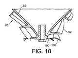
インペラハウジング72は、略切頭円錐形状であり、下部端部が一次空気流を受け入れる比較的小さい円形の空気入口78と(図示するように)、上部端部の比較的大きい円形の空気出口80と(図示するように)を備え、モータハウジングがインペラハウジング72に収容される場合、インペラハウジングの中にディフューザ70が配置される。環状入口部材82は、インペラハウジング72の外面に連結され、一次空気流をインペラハウジング72の空気入口78に向かって案内する。
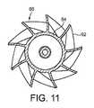
インペラ60は、略円錐形状のハブ84と、該ハブ84に連結された複数のインペラブレード86と、該ブレード86に連結されハブ84及びブレード86を取り囲む略切頭円錐形状のシュラウド88とを備える。ブレード86は、好ましくは、ハブ84と一体であり、好ましくは、プラスチック材料で作られている。ハブ84の厚さx1は、1mmから3mmの範囲にある。ハブ84は、モータハウジングの下部セクション66の外面の円錐形状と同じ円錐形状の内面を有する。ハブ84は、同様に1mmから3mmの範囲にある距離x2だけモータハウジングから離間している。The
インペラ60のハブ84及びブレード86は、図7から図11により詳細に示されている。本実施例では、インペラ60は、9枚のブレード86を備える。各ブレード86は、ハブ84の周りに60度から120度の範囲の角度で部分的に延び、本実施例では、各ブレード86はハブ84の周りに約105度の角度で延びる。各ブレード86は、ハブ84に連結される内側縁90と、該内側縁90とは反対側に配置された外側縁92とを有する。また、各ブレード86は、インペラハウジング74の空気入口74に隣接して配置される前縁94、ブレード86の先端94とは反対端に配置された後縁96、及び前縁94と外側縁92との交差部に配置されたブレード先端98を有する。 The
各側縁90、92の長さは、前縁94及び後縁96の長さよりも大きい。外側縁92の長さは、好ましくは、70mmから90mmの範囲であり、本実施例では約80mmである。前縁94の長さは、好ましくは、15mmから30mmの範囲であり、本実施例では、約20mmである。後縁96の長さは、好ましくは、5mmから15mmの範囲であり、本実施例では、約10mmである。ブレード86の幅は、前縁94から後縁96に向かって徐々に減少している。 The length of each
各ブレード86の後縁96は、好ましくは、直線状である。各ブレード86の前縁94は、ハブ84に隣接して配置される内側部分100と、ブレード先端98に隣接して配置された外側部分102とを備える。前縁94の内側部分100は、前縁94の長さの30%から80%の範囲で延びる。本実施例では、内側部分100は外側部分102よりも長く、前縁94の長さの50%から70%の範囲で延びる。 The trailing
ブレード86の形状は、ブレード86の一部を横切る圧力勾配を低減することで、インペラ64の回転時に発生する騒音を最小にするように設計されている。これらの圧力勾配の低減により、一次空気流がブレード86から剥離する傾向が低減され、結果的に空気流内の乱流が低減される。 The shape of the
前縁94の外側部分102は、内側部分100からブレード先端98まで、前方に湾曲している。各ブレード86の前縁94のブレード先端98に向かう局部的な前方への湾曲は、ブレード86のハブから先端への負荷ピークを低減できる。外側部分102は、凹形状であり、内側部分100からブレード先端98へ前方に湾曲している。ブレード86のブレード間負荷を低減するために、内側部分100は、内側縁90の長さが外側縁92の長さ近づくように、ハブ86から外側部分102へ後方に湾曲している。本実施例では、前縁94の内側部分100は、凸形状であり、ハブ84から前縁94の外側部分102へ後方に湾曲して、内側縁90の長さを最大にしている。 The
各ブレード86の長さに沿ったブレード間負荷は、各ブレード86の傾斜角、つまりブレード86とハブ84から半径方向外向きに延びる平面との間に規定される角度を制御することにより低減される。各ブレード86は、ブレード86の前縁94に隣接する最大値から、ブレード86の後縁96に隣接する最小値まで、ブレード86の長さに沿って変動する傾斜角を有する。傾斜角は、好ましくは、ブレード86が前縁94においてインペラの回転方向で前方に傾くように前縁94で正であり、一方、傾斜角は、好ましくは、ブレード86がインペラの回転方向から後方に離れるように後縁96で負である。これは、図9に示されている。傾斜角の最大値は、好ましくは、15度から30度の範囲であり、本実施例では約20度であり、傾斜角の最小値は、好ましくは、−20度から−30度の範囲であり、本実施例では約−25度である。傾斜角は、ブレード86の前縁94と後縁96との間の中程部分又はその近くで0度である。 The blade-to-blade load along the length of each
各ブレード86の後縁96におけるブレード間負荷を最小にするように、ブレードの厚さは、好ましくは、後縁96で最小値とされている。ブレード86の厚さの最大値は、好ましくは、前縁94と後縁96との間の中程に設定され、この最大値は、好ましくは、0.9mmから1.1mmの範囲にある。本実施例では、この最大値は、約1mmである。最小厚さは、好ましくは、0.2mmから0.8mmの範囲にある。前縁94におけるブレード86の厚さは、好ましくは、これら最大値と最小値との間である。ブレードの厚さの、それらの長さに沿った変動は図10に見られる。 The blade thickness is preferably minimized at the trailing
図4に戻って、複数のゴムマウント108は、インペラハウジング72に連結されている。これらのマウント108は、インペラハウジング72が基部12内に配置される場合、基部12の主本体セクション50内に配置及び連結された支持体110にそれぞれ設けられている。電気ケーブル112は、主制御回路58から、本体12の主本体部分50及び下側本体部分52、並びにインペラハウジング74及びモータバケットに形成された開口を通って、モータ64へ延びている。 Returning to FIG. 4, the plurality of rubber mounts 108 are connected to the
好ましくは、本体12は、該本体12からのノイズ放出を低減する消音発泡体を備える。本実施形態では、本体12の主本体部分50は、空気入口14の下に配置される第1の発泡部材114と、モータバケット内に配置される第2の環状発泡部材116とを備える。 Preferably, the main body 12 includes a sound deadening foam that reduces noise emission from the main body 12. In the present embodiment, the
送風機10の作動に際し、ユーザはユーザインタフェースのボタン22を押圧し、これに応答して、主制御回路58は、モータ64を駆動してインペラ60を回転させる。インペラ60の回転は、空気入口14を通って本体12内へ引き込まれる一次空気流を引き起こす。ユーザは、ユーザインタフェースのダイアル26を操作することにより、モータ64の速度、従って空気入口14を通って本体12内へ引き込まれる空気の割合を制御できる。インペラ60が発生する一次空気流は、モータ64の速度に応じて、毎秒20リットルと30リットルとの間とすることができる。一次空気流は、本体12の空気出口54を通る前に、順に、インペラハウジング72とディフューザ70を通り、上部ケーシング18に入る。本体12の空気出口54における一次空気流の圧力は、少なくとも150Pとすることができ、好ましくは、250Paから1.5kPaの範囲にある。 In operating the blower 10, the user presses the
上部ケーシング18内で、一次空気流は、ケーシング14の開口部32の周りで反対方向に流れる2つの空気ストリームに分流される。空気ストリームが内部通路35を通る際に、空気は、空気出口20から噴出される。空気出口20から噴出される一次空気流は、上部ケーシング18のコアンダ面36の上に向けられ、外部環境から、特に空気出口20の周りの領域からの及び上部ケーシング18の後部の周りからの空気を同伴することにより、二次空気流を発生させる。二次空気流は、上部ケーシング18の中心開口部32を通って流れ、そこで、二次空気流は一次空気流と合体して、上部ケーシング18から前方へ噴出される合体空気流又は空気の流れを生成する。 Within the
Claims (16)
Translated fromJapanese空気流が通って前記送風機に引き込まれる空気入口を備える第1のケーシングと、該第1のケーシングに連結されるとともに、前記空気流が通って前記送風機から噴出される空気出口を備えた第2のケーシングとを備え、
前記第1のケーシングは、
空気入口及び空気出口を有するインペラハウジングと、
前記インペラハウジング内に配置され、前記第1のケーシングの前記空気入口を介して前記空気流を引き込む混流インペラと、
前記インペラを駆動するモータと、
を備え、
前記インペラは、前記モータに連結される実質的に円錐形状のハブと、該ハブに連結される複数のブレードとを備え、該ブレードの各々は、前記インペラハウジングの前記空気入口に隣接して配置される前縁と、後縁と、前記ハブの外面に連結され、その周りに部分的に延びる内側縁と、該内側縁の反対側に配置される外側縁と、前記前縁と前記外側縁との交差部に配置されるブレード先端とを備え、
前記前縁は、前記ハブに隣接して配置される内側部分と、前記ブレード先端に隣接して配置される外側部分とを備え、前記内側部分は、前記ハブから前記外側部分へ後方に湾曲し、前記外側部分は、前記内側部分から前記ブレード先端へ前方に湾曲する、送風機。An air blower that generates an air flow in a room,
A first casing provided with an air inlet through which an air flow is drawn and drawn into the blower; and a second casing connected to the first casing and provided with an air outlet through which the air flow passes and is ejected from the blower. With a casing of
The first casing is
An impeller housing having an air inlet and an air outlet;
A mixed flow impeller disposed within the impeller housing and drawing the air flow through the air inlet of the first casing;
A motor for driving the impeller;
With
The impeller includes a substantially conical hub coupled to the motor and a plurality of blades coupled to the hub, each blade disposed adjacent to the air inlet of the impeller housing. A leading edge, a trailing edge, an inner edge connected to and partially extending around the outer surface of the hub, an outer edge disposed opposite the inner edge, the leading edge and the outer edge Blade tip arranged at the intersection with
The leading edge includes an inner portion disposed adjacent to the hub and an outer portion disposed adjacent to the blade tip, the inner portion curved backward from the hub to the outer portion. The blower, wherein the outer portion curves forward from the inner portion to the blade tip.
Applications Claiming Priority (3)
| Application Number | Priority Date | Filing Date | Title |
|---|---|---|---|
| GB1020419.6AGB2486019B (en) | 2010-12-02 | 2010-12-02 | A fan |
| GB1020419.6 | 2010-12-02 | ||
| PCT/GB2011/052109WO2012072996A1 (en) | 2010-12-02 | 2011-10-28 | A fan |
Publications (2)
| Publication Number | Publication Date |
|---|---|
| JP2014501873Atrue JP2014501873A (en) | 2014-01-23 |
| JP5592024B2 JP5592024B2 (en) | 2014-09-17 |
Family
ID=43531342
Family Applications (1)
| Application Number | Title | Priority Date | Filing Date |
|---|---|---|---|
| JP2013541420AExpired - Fee RelatedJP5592024B2 (en) | 2010-12-02 | 2011-10-28 | Blower |
Country Status (6)
| Country | Link |
|---|---|
| US (1) | US9745996B2 (en) |
| JP (1) | JP5592024B2 (en) |
| CN (2) | CN102562652B (en) |
| GB (2) | GB2486019B (en) |
| TW (1) | TWM428255U (en) |
| WO (1) | WO2012072996A1 (en) |
Cited By (6)
| Publication number | Priority date | Publication date | Assignee | Title |
|---|---|---|---|---|
| JP2015212547A (en)* | 2014-05-05 | 2015-11-26 | ジール・アベッグ エスエー | Impeller wheel for diagonal or radial fans, injection molding tool for manufacturing such impeller wheel, and device comprising at least one impeller wheel |
| JP2019023433A (en)* | 2017-07-21 | 2019-02-14 | 日本電産株式会社 | Blower and cleaner |
| JP2019124142A (en)* | 2018-01-12 | 2019-07-25 | 日本電産株式会社 | Blower module and cleaner |
| KR20210029270A (en)* | 2018-07-23 | 2021-03-15 | 다이슨 테크놀러지 리미티드 | Wearable air purifier |
| US11236767B2 (en) | 2016-10-07 | 2022-02-01 | Mitsubishi Electric Corporation | Electric blower, electric vacuum cleaner and hand dryer |
| US12311204B2 (en) | 2018-07-23 | 2025-05-27 | Dyson Technology Limited | Wearable air purifier |
Families Citing this family (38)
| Publication number | Priority date | Publication date | Assignee | Title |
|---|---|---|---|---|
| GB2468322B (en) | 2009-03-04 | 2011-03-16 | Dyson Technology Ltd | Tilting fan stand |
| GB2468312A (en) | 2009-03-04 | 2010-09-08 | Dyson Technology Ltd | Fan assembly |
| GB2483448B (en) | 2010-09-07 | 2015-12-02 | Dyson Technology Ltd | A fan |
| JP5879103B2 (en)* | 2011-11-17 | 2016-03-08 | 株式会社日立製作所 | Centrifugal fluid machine |
| GB2498547B (en) | 2012-01-19 | 2015-02-18 | Dyson Technology Ltd | A fan |
| GB2518935B (en) | 2012-05-16 | 2016-01-27 | Dyson Technology Ltd | A fan |
| GB2532557B (en) | 2012-05-16 | 2017-01-11 | Dyson Technology Ltd | A fan comprsing means for suppressing noise |
| EP2850324A2 (en)* | 2012-05-16 | 2015-03-25 | Dyson Technology Limited | A fan |
| GB2503907B (en) | 2012-07-11 | 2014-05-28 | Dyson Technology Ltd | A fan assembly |
| JP5606515B2 (en)* | 2012-12-13 | 2014-10-15 | 三菱重工業株式会社 | Compressor |
| CN103291655A (en)* | 2013-06-24 | 2013-09-11 | 浙江理工大学 | Bladeless fan turbine device with splitter blades |
| GB2516058B (en) | 2013-07-09 | 2016-12-21 | Dyson Technology Ltd | A fan assembly with an oscillation and tilt mechanism |
| JP6064179B2 (en)* | 2014-06-11 | 2017-01-25 | パナソニックIpマネジメント株式会社 | Temperature conditioning unit, temperature conditioning system, and vehicle equipped with temperature conditioning unit |
| JP6678302B2 (en)* | 2015-07-24 | 2020-04-08 | パナソニックIpマネジメント株式会社 | Temperature control unit, temperature control system, vehicle |
| CN105179278A (en)* | 2015-10-30 | 2015-12-23 | 佛山市神风航空科技有限公司 | Electric conical impeller blower fan |
| CN105179277A (en)* | 2015-10-30 | 2015-12-23 | 佛山市神风航空科技有限公司 | Conical impeller fan |
| US10280935B2 (en) | 2016-04-26 | 2019-05-07 | Parker-Hannifin Corporation | Integral fan and airflow guide |
| CA2966053C (en) | 2016-05-05 | 2022-10-18 | Tti (Macao Commercial Offshore) Limited | Mixed flow fan |
| ITUA20163576A1 (en)* | 2016-05-18 | 2017-11-18 | De Longhi Appliances Srl | FAN |
| CA2936339C (en)* | 2016-07-18 | 2019-02-12 | Carl R. Bachellier | Low shear, low velocity differential, impeller having a progressively tapered hub volume with periods formed into a bottom surface |
| US10151329B2 (en) | 2017-02-04 | 2018-12-11 | Hamilton G. Moore | Systems and methods for flying sheet materials |
| WO2018157337A1 (en)* | 2017-03-01 | 2018-09-07 | 美的集团股份有限公司 | Fan head and bladeless fan |
| US11384956B2 (en) | 2017-05-22 | 2022-07-12 | Sharkninja Operating Llc | Modular fan assembly with articulating nozzle |
| US10760587B2 (en) | 2017-06-06 | 2020-09-01 | Elliott Company | Extended sculpted twisted return channel vane arrangement |
| CN108252949A (en)* | 2018-01-29 | 2018-07-06 | 广东美的厨房电器制造有限公司 | Mixed flow wind wheel and flow-mixing blower fan |
| WO2019191237A1 (en)* | 2018-03-29 | 2019-10-03 | Walmart Apollo, Llc | Aerial vehicle turbine system |
| JP6737839B2 (en)* | 2018-06-19 | 2020-08-12 | 三菱重工コンプレッサ株式会社 | Impeller, centrifugal fluid machine, and fluid device |
| AU2020288201A1 (en)* | 2019-06-07 | 2022-02-03 | Beacon Lighting International Limited | Airflow device |
| EP4189251A1 (en)* | 2020-07-31 | 2023-06-07 | Safran Power USA, LLC | Rotating machine with cooling fan |
| WO2022252825A1 (en)* | 2021-06-04 | 2022-12-08 | 深圳市几素科技有限公司 | Hanging neck fan |
| CN216844967U (en)* | 2021-11-02 | 2022-06-28 | 深圳秒新科技有限公司 | Humidifier |
| US11754088B2 (en)* | 2021-12-03 | 2023-09-12 | Hamilton Sundstrand Corporation | Fan impeller with thin blades |
| USD1067419S1 (en)* | 2022-04-27 | 2025-03-18 | Foshan Samyoo Electronic Co., Ltd. | Impeller |
| KR102808433B1 (en)* | 2022-12-21 | 2025-05-16 | 엘지전자 주식회사 | Vacuum cleaner |
| JP2024158726A (en)* | 2023-04-28 | 2024-11-08 | 三星電子株式会社 | Impellers, blowers and vacuum cleaners |
| WO2025038080A1 (en)* | 2023-08-15 | 2025-02-20 | Safran Electrical & Power Usa, Llc | Mixed flow cooling fan |
| WO2025054708A1 (en)* | 2023-09-13 | 2025-03-20 | Silent Propulsion Inc. | Fluid displacement or propulsion device having a progressively tapered hub volume with periods formed into a surface, system and methods for moving a fluid or causing propulsion |
| WO2025171159A1 (en)* | 2024-02-09 | 2025-08-14 | Air Distribution Technologies Ip, Llc | Hvac ventilator with mixed flow fan wheel |
Citations (2)
| Publication number | Priority date | Publication date | Assignee | Title |
|---|---|---|---|---|
| JPS5990797A (en)* | 1982-09-30 | 1984-05-25 | ゼネラル・エレクトリツク・カンパニイ | Centrifugal compressor and compression method |
| JP2010203443A (en)* | 2009-03-04 | 2010-09-16 | Dyson Technology Ltd | Fan assembly |
Family Cites Families (390)
| Publication number | Priority date | Publication date | Assignee | Title |
|---|---|---|---|---|
| GB593828A (en) | 1945-06-14 | 1947-10-27 | Dorothy Barker | Improvements in or relating to propeller fans |
| GB601222A (en) | 1944-10-04 | 1948-04-30 | Berkeley & Young Ltd | Improvements in, or relating to, electric fans |
| US1357261A (en) | 1918-10-02 | 1920-11-02 | Ladimir H Svoboda | Fan |
| US1767060A (en) | 1928-10-04 | 1930-06-24 | W H Addington | Electric motor-driven desk fan |
| US2014185A (en) | 1930-06-25 | 1935-09-10 | Martin Brothers Electric Compa | Drier |
| GB383498A (en) | 1931-03-03 | 1932-11-17 | Spontan Ab | Improvements in or relating to fans, ventilators, or the like |
| US1896869A (en) | 1931-07-18 | 1933-02-07 | Master Electric Co | Electric fan |
| US2035733A (en) | 1935-06-10 | 1936-03-31 | Marathon Electric Mfg | Fan motor mounting |
| US2210458A (en) | 1936-11-16 | 1940-08-06 | Lester S Keilholtz | Method of and apparatus for air conditioning |
| US2115883A (en) | 1937-04-21 | 1938-05-03 | Sher Samuel | Lamp |
| US2258961A (en) | 1939-07-26 | 1941-10-14 | Prat Daniel Corp | Ejector draft control |
| US2336295A (en) | 1940-09-25 | 1943-12-07 | Reimuller Caryl | Air diverter |
| GB641622A (en) | 1942-05-06 | 1950-08-16 | Fernan Oscar Conill | Improvements in or relating to hair drying |
| US2433795A (en) | 1945-08-18 | 1947-12-30 | Westinghouse Electric Corp | Fan |
| US2476002A (en) | 1946-01-12 | 1949-07-12 | Edward A Stalker | Rotating wing |
| US2547448A (en) | 1946-02-20 | 1951-04-03 | Demuth Charles | Hot-air space heater |
| US2473325A (en) | 1946-09-19 | 1949-06-14 | E A Lab Inc | Combined electric fan and air heating means |
| US2544379A (en) | 1946-11-15 | 1951-03-06 | Oscar J Davenport | Ventilating apparatus |
| US2488467A (en) | 1947-09-12 | 1949-11-15 | Lisio Salvatore De | Motor-driven fan |
| GB633273A (en) | 1948-02-12 | 1949-12-12 | Albert Richard Ponting | Improvements in or relating to air circulating apparatus |
| US2510132A (en) | 1948-05-27 | 1950-06-06 | Morrison Hackley | Oscillating fan |
| GB661747A (en) | 1948-12-18 | 1951-11-28 | British Thomson Houston Co Ltd | Improvements in and relating to oscillating fans |
| US2620127A (en) | 1950-02-28 | 1952-12-02 | Westinghouse Electric Corp | Air translating apparatus |
| US2583374A (en) | 1950-10-18 | 1952-01-22 | Hydraulic Supply Mfg Company | Exhaust fan |
| FR1033034A (en) | 1951-02-23 | 1953-07-07 | Articulated stabilizer support for fan with flexible propellers and variable speeds | |
| US2813673A (en) | 1953-07-09 | 1957-11-19 | Gilbert Co A C | Tiltable oscillating fan |
| US2838229A (en) | 1953-10-30 | 1958-06-10 | Roland J Belanger | Electric fan |
| US2765977A (en) | 1954-10-13 | 1956-10-09 | Morrison Hackley | Electric ventilating fans |
| FR1119439A (en) | 1955-02-18 | 1956-06-20 | Enhancements to portable and wall fans | |
| US2830779A (en) | 1955-02-21 | 1958-04-15 | Lau Blower Co | Fan stand |
| NL110393C (en) | 1955-11-29 | 1965-01-15 | Bertin & Cie | |
| CH346643A (en) | 1955-12-06 | 1960-05-31 | K Tateishi Arthur | Electric fan |
| US2808198A (en) | 1956-04-30 | 1957-10-01 | Morrison Hackley | Oscillating fans |
| BE560119A (en) | 1956-09-13 | |||
| GB863124A (en) | 1956-09-13 | 1961-03-15 | Sebac Nouvelle Sa | New arrangement for putting gases into movement |
| US2922570A (en) | 1957-12-04 | 1960-01-26 | Burris R Allen | Automatic booster fan and ventilating shield |
| US3004403A (en) | 1960-07-21 | 1961-10-17 | Francis L Laporte | Refrigerated space humidification |
| DE1291090B (en) | 1963-01-23 | 1969-03-20 | Schmidt Geb Halm Anneliese | Device for generating an air flow |
| DE1457461A1 (en) | 1963-10-01 | 1969-02-20 | Siemens Elektrogeraete Gmbh | Suitcase-shaped hair dryer |
| FR1387334A (en) | 1963-12-21 | 1965-01-29 | Hair dryer capable of blowing hot and cold air separately | |
| US3270655A (en) | 1964-03-25 | 1966-09-06 | Howard P Guirl | Air curtain door seal |
| US3339867A (en) | 1966-06-28 | 1967-09-05 | Electrolux Corp | Motor mount |
| US3518776A (en) | 1967-06-03 | 1970-07-07 | Bremshey & Co | Blower,particularly for hair-drying,laundry-drying or the like |
| US3444817A (en)* | 1967-08-23 | 1969-05-20 | William J Caldwell | Fluid pump |
| US3487555A (en) | 1968-01-15 | 1970-01-06 | Hoover Co | Portable hair dryer |
| US3495343A (en) | 1968-02-20 | 1970-02-17 | Rayette Faberge | Apparatus for applying air and vapor to the face and hair |
| US3503138A (en) | 1969-05-19 | 1970-03-31 | Oster Mfg Co John | Hair dryer |
| GB1278606A (en) | 1969-09-02 | 1972-06-21 | Oberlind Veb Elektroinstall | Improvements in or relating to transverse flow fans |
| US3645007A (en) | 1970-01-14 | 1972-02-29 | Sunbeam Corp | Hair dryer and facial sauna |
| DE2944027A1 (en) | 1970-07-22 | 1981-05-07 | Erevanskyj politechničeskyj institut imeni Karla Marksa, Erewan | EJECTOR ROOM AIR CONDITIONER OF THE CENTRAL AIR CONDITIONING |
| US3724092A (en) | 1971-07-12 | 1973-04-03 | Westinghouse Electric Corp | Portable hair dryer |
| GB1403188A (en) | 1971-10-22 | 1975-08-28 | Olin Energy Systems Ltd | Fluid flow inducing apparatus |
| US3743186A (en) | 1972-03-14 | 1973-07-03 | Src Lab | Air gun |
| US3885891A (en) | 1972-11-30 | 1975-05-27 | Rockwell International Corp | Compound ejector |
| US3795367A (en) | 1973-04-05 | 1974-03-05 | Src Lab | Fluid device using coanda effect |
| US3872916A (en) | 1973-04-05 | 1975-03-25 | Int Harvester Co | Fan shroud exit structure |
| US4037991A (en) | 1973-07-26 | 1977-07-26 | The Plessey Company Limited | Fluid-flow assisting devices |
| US3875745A (en) | 1973-09-10 | 1975-04-08 | Wagner Minning Equipment Inc | Venturi exhaust cooler |
| GB1434226A (en) | 1973-11-02 | 1976-05-05 | Roberts S A | Pumps |
| US3943329A (en) | 1974-05-17 | 1976-03-09 | Clairol Incorporated | Hair dryer with safety guard air outlet nozzle |
| CA1055344A (en) | 1974-05-17 | 1979-05-29 | International Harvester Company | Heat transfer system employing a coanda effect producing fan shroud exit |
| US4180130A (en) | 1974-05-22 | 1979-12-25 | International Harvester Company | Heat exchange apparatus including a toroidal-type radiator |
| US4184541A (en) | 1974-05-22 | 1980-01-22 | International Harvester Company | Heat exchange apparatus including a toroidal-type radiator |
| GB1501473A (en) | 1974-06-11 | 1978-02-15 | Charbonnages De France | Fans |
| GB1495013A (en) | 1974-06-25 | 1977-12-14 | British Petroleum Co | Coanda unit |
| GB1593391A (en) | 1977-01-28 | 1981-07-15 | British Petroleum Co | Flare |
| JPS517258A (en) | 1974-07-11 | 1976-01-21 | Tsudakoma Ind Co Ltd | YOKOITO CHORYUSOCHI |
| DE2451557C2 (en) | 1974-10-30 | 1984-09-06 | Arnold Dipl.-Ing. 8904 Friedberg Scheel | Device for ventilating a occupied zone in a room |
| US4136735A (en) | 1975-01-24 | 1979-01-30 | International Harvester Company | Heat exchange apparatus including a toroidal-type radiator |
| US4061188A (en) | 1975-01-24 | 1977-12-06 | International Harvester Company | Fan shroud structure |
| US4173995A (en) | 1975-02-24 | 1979-11-13 | International Harvester Company | Recirculation barrier for a heat transfer system |
| US4332529A (en) | 1975-08-11 | 1982-06-01 | Morton Alperin | Jet diffuser ejector |
| US4046492A (en) | 1976-01-21 | 1977-09-06 | Vortec Corporation | Air flow amplifier |
| JPS5351608A (en) | 1976-10-20 | 1978-05-11 | Asahi Giken Kk | Fluid conveying tube to be installed under the water surface |
| DK140426B (en) | 1976-11-01 | 1979-08-27 | Arborg O J M | Propulsion nozzle for means of transport in air or water. |
| US4113416A (en) | 1977-02-24 | 1978-09-12 | Ishikawajima-Harima Jukogyo Kabushiki Kaisha | Rotary burner |
| JPS56167897A (en) | 1980-05-28 | 1981-12-23 | Toshiba Corp | Fan |
| AU7279281A (en) | 1980-07-17 | 1982-01-21 | General Conveyors Ltd. | Variable nozzle for jet pump |
| MX147915A (en) | 1981-01-30 | 1983-01-31 | Philips Mexicana S A De C V | ELECTRIC FAN |
| JPS57157097A (en) | 1981-03-20 | 1982-09-28 | Sanyo Electric Co Ltd | Fan |
| US4568243A (en) | 1981-10-08 | 1986-02-04 | Barry Wright Corporation | Vibration isolating seal for mounting fans and blowers |
| CH662623A5 (en) | 1981-10-08 | 1987-10-15 | Wright Barry Corp | INSTALLATION FRAME FOR A FAN. |
| GB2111125A (en) | 1981-10-13 | 1983-06-29 | Beavair Limited | Apparatus for inducing fluid flow by Coanda effect |
| US4448354A (en) | 1982-07-23 | 1984-05-15 | The United States Of America As Represented By The Secretary Of The Air Force | Axisymmetric thrust augmenting ejector with discrete primary air slot nozzles |
| US4653976A (en)* | 1982-09-30 | 1987-03-31 | General Electric Company | Method of compressing a fluid flow in a multi stage centrifugal impeller |
| FR2534983A1 (en) | 1982-10-20 | 1984-04-27 | Chacoux Claude | Jet supersonic compressor |
| US4718870A (en) | 1983-02-15 | 1988-01-12 | Techmet Corporation | Marine propulsion system |
| JPS59167984A (en) | 1983-03-12 | 1984-09-21 | 日本特殊陶業株式会社 | Resistor for ignition plug and method of producing same |
| JPS60105896A (en) | 1983-11-14 | 1985-06-11 | Mitsubishi Heavy Ind Ltd | Air and water extracting device for water heat exchanger |
| KR900001873B1 (en) | 1984-06-14 | 1990-03-26 | 산요덴끼 가부시끼가이샤 | Ultrasonic humidifier |
| JP2594029B2 (en) | 1984-07-25 | 1997-03-26 | 三洋電機株式会社 | Ultrasonic humidifier |
| JPS61116093A (en) | 1984-11-12 | 1986-06-03 | Matsushita Electric Ind Co Ltd | Fan |
| FR2574854B1 (en) | 1984-12-17 | 1988-10-28 | Peugeot Aciers Et Outillage | MOTOR FAN, PARTICULARLY FOR MOTOR VEHICLE, FIXED ON SOLID BODY SUPPORT ARMS |
| US4630475A (en) | 1985-03-20 | 1986-12-23 | Sharp Kabushiki Kaisha | Fiber optic level sensor for humidifier |
| JPS61280787A (en) | 1985-05-30 | 1986-12-11 | Sanyo Electric Co Ltd | Fan |
| US4832576A (en) | 1985-05-30 | 1989-05-23 | Sanyo Electric Co., Ltd. | Electric fan |
| US4703152A (en) | 1985-12-11 | 1987-10-27 | Holmes Products Corp. | Tiltable and adjustably oscillatable portable electric heater/fan |
| GB2185533A (en) | 1986-01-08 | 1987-07-22 | Rolls Royce | Ejector pumps |
| GB2185531B (en) | 1986-01-20 | 1989-11-22 | Mitsubishi Electric Corp | Electric fans |
| US4732539A (en) | 1986-02-14 | 1988-03-22 | Holmes Products Corp. | Oscillating fan |
| JPS62223494A (en) | 1986-03-21 | 1987-10-01 | Uingu:Kk | Cold air fan |
| US4850804A (en) | 1986-07-07 | 1989-07-25 | Tatung Company Of America, Inc. | Portable electric fan having a universally adjustable mounting |
| US4790133A (en) | 1986-08-29 | 1988-12-13 | General Electric Company | High bypass ratio counterrotating turbofan engine |
| FR2603953B1 (en)* | 1986-09-12 | 1991-02-22 | Peugeot Aciers Et Outillage | PROPELLER BLADE AND ITS APPLICATION TO MOTOR FANS |
| DE3644567C2 (en) | 1986-12-27 | 1993-11-18 | Ltg Lufttechnische Gmbh | Process for blowing supply air into a room |
| JPH0781559B2 (en) | 1987-01-20 | 1995-08-30 | 三洋電機株式会社 | Blower |
| JPS63306340A (en) | 1987-06-06 | 1988-12-14 | Koichi Hidaka | Bacteria preventive ultrasonic humidifier incorporating sterilizing lamp lighting circuit |
| JPH079279B2 (en) | 1987-07-15 | 1995-02-01 | 三菱重工業株式会社 | Heat insulation structure on the bottom of tank and its construction method |
| JPS6483884A (en) | 1987-09-28 | 1989-03-29 | Matsushita Seiko Kk | Chargeable electric fan |
| JPH0660638B2 (en) | 1987-10-07 | 1994-08-10 | 松下電器産業株式会社 | Mixed flow impeller |
| JPH01138399A (en) | 1987-11-24 | 1989-05-31 | Sanyo Electric Co Ltd | Blowing fan |
| JPH0633850B2 (en) | 1988-03-02 | 1994-05-02 | 三洋電機株式会社 | Device elevation angle adjustment device |
| JPH0636437Y2 (en) | 1988-04-08 | 1994-09-21 | 耕三 福田 | Air circulation device |
| US4878620A (en) | 1988-05-27 | 1989-11-07 | Tarleton E Russell | Rotary vane nozzle |
| US4978281A (en) | 1988-08-19 | 1990-12-18 | Conger William W Iv | Vibration dampened blower |
| US6293121B1 (en) | 1988-10-13 | 2001-09-25 | Gaudencio A. Labrador | Water-mist blower cooling system and its new applications |
| JPH02146294A (en) | 1988-11-24 | 1990-06-05 | Japan Air Curtain Corp | Air blower |
| FR2640857A1 (en) | 1988-12-27 | 1990-06-29 | Seb Sa | Hairdryer with an air exit flow of modifiable form |
| JPH02211400A (en) | 1989-02-08 | 1990-08-22 | Mitsubishi Electric Corp | Mixed flow blower |
| JPH02218890A (en) | 1989-02-20 | 1990-08-31 | Matsushita Seiko Co Ltd | Oscillating device for fan |
| JPH02248690A (en) | 1989-03-22 | 1990-10-04 | Hitachi Ltd | Fan |
| US5203521A (en) | 1989-05-12 | 1993-04-20 | Day Terence R | Annular body aircraft |
| JPH033419A (en) | 1989-05-30 | 1991-01-09 | Nec Corp | Phase synchronization circuit |
| JPH0695808B2 (en) | 1989-07-14 | 1994-11-24 | 三星電子株式会社 | Induction motor control circuit and control method |
| GB2236804A (en) | 1989-07-26 | 1991-04-17 | Anthony Reginald Robins | Compound nozzle |
| GB2237323A (en) | 1989-10-06 | 1991-05-01 | Coal Ind | Fan silencer apparatus |
| GB2240268A (en) | 1990-01-29 | 1991-07-31 | Wik Far East Limited | Hair dryer |
| US5061405A (en) | 1990-02-12 | 1991-10-29 | Emerson Electric Co. | Constant humidity evaporative wicking filter humidifier |
| FR2658593B1 (en) | 1990-02-20 | 1992-05-07 | Electricite De France | AIR INLET. |
| GB9005709D0 (en) | 1990-03-14 | 1990-05-09 | S & C Thermofluids Ltd | Coanda flue gas ejectors |
| JP2619548B2 (en) | 1990-03-19 | 1997-06-11 | 株式会社日立製作所 | Blower |
| JPH0443895A (en) | 1990-06-08 | 1992-02-13 | Matsushita Seiko Co Ltd | Controller of electric fan |
| USD325435S (en) | 1990-09-24 | 1992-04-14 | Vornado Air Circulation Systems, Inc. | Fan support base |
| JPH0499258U (en) | 1991-01-14 | 1992-08-27 | ||
| CN2085866U (en) | 1991-03-16 | 1991-10-02 | 郭维涛 | Portable electric fan |
| US5188508A (en) | 1991-05-09 | 1993-02-23 | Comair Rotron, Inc. | Compact fan and impeller |
| JPH04366330A (en) | 1991-06-12 | 1992-12-18 | Taikisha Ltd | Induction type blowing device |
| DE4127134B4 (en) | 1991-08-15 | 2004-07-08 | Papst Licensing Gmbh & Co. Kg | diagonal fan |
| US5168722A (en) | 1991-08-16 | 1992-12-08 | Walton Enterprises Ii, L.P. | Off-road evaporative air cooler |
| JPH05263786A (en) | 1992-07-23 | 1993-10-12 | Sanyo Electric Co Ltd | Electric fan |
| JPH05157093A (en) | 1991-12-03 | 1993-06-22 | Sanyo Electric Co Ltd | Electric fan |
| JPH05164089A (en) | 1991-12-10 | 1993-06-29 | Matsushita Electric Ind Co Ltd | Axial fan motor |
| US5296769A (en) | 1992-01-24 | 1994-03-22 | Electrolux Corporation | Air guide assembly for an electric motor and methods of making |
| US5762661A (en) | 1992-01-31 | 1998-06-09 | Kleinberger; Itamar C. | Mist-refining humidification system having a multi-direction, mist migration path |
| CN2111392U (en) | 1992-02-26 | 1992-07-29 | 张正光 | Switch device for electric fan |
| JP3109277B2 (en) | 1992-09-09 | 2000-11-13 | 松下電器産業株式会社 | Clothes dryer |
| JPH06147188A (en) | 1992-11-10 | 1994-05-27 | Hitachi Ltd | Electric fan |
| US5411371A (en) | 1992-11-23 | 1995-05-02 | Chen; Cheng-Ho | Swiveling electric fan |
| US5310313A (en) | 1992-11-23 | 1994-05-10 | Chen C H | Swinging type of electric fan |
| JPH06257591A (en) | 1993-03-08 | 1994-09-13 | Hitachi Ltd | Fan |
| JPH06280800A (en) | 1993-03-29 | 1994-10-04 | Matsushita Seiko Co Ltd | Induced blast device |
| JPH06336113A (en) | 1993-05-28 | 1994-12-06 | Sawafuji Electric Co Ltd | Automotive humidifier |
| US5317815A (en) | 1993-06-15 | 1994-06-07 | Hwang Shyh Jye | Grille assembly for hair driers |
| JPH0674190A (en) | 1993-07-30 | 1994-03-15 | Sanyo Electric Co Ltd | Fan |
| US5402938A (en) | 1993-09-17 | 1995-04-04 | Exair Corporation | Fluid amplifier with improved operating range using tapered shim |
| US5425902A (en) | 1993-11-04 | 1995-06-20 | Tom Miller, Inc. | Method for humidifying air |
| GB2285504A (en) | 1993-12-09 | 1995-07-12 | Alfred Slack | Hot air distribution |
| JPH07190443A (en) | 1993-12-24 | 1995-07-28 | Matsushita Seiko Co Ltd | Blower equipment |
| US5407324A (en) | 1993-12-30 | 1995-04-18 | Compaq Computer Corporation | Side-vented axial fan and associated fabrication methods |
| JP2921384B2 (en) | 1994-03-04 | 1999-07-19 | 株式会社日立製作所 | Mixed flow fan |
| DE4418014A1 (en) | 1994-05-24 | 1995-11-30 | E E T Umwelt Und Gastechnik Gm | Method of conveying and mixing a first fluid with a second fluid under pressure |
| CA2192327C (en)* | 1994-06-10 | 2005-10-04 | Mehrdad Zangeneh | Centrifugal or mixed flow turbomachinery |
| US5645769A (en) | 1994-06-17 | 1997-07-08 | Nippondenso Co., Ltd. | Humidified cool wind system for vehicles |
| JP3614467B2 (en) | 1994-07-06 | 2005-01-26 | 鎌田バイオ・エンジニアリング株式会社 | Jet pump |
| DE19510397A1 (en) | 1995-03-22 | 1996-09-26 | Piller Gmbh | Blower unit for car=wash |
| CA2155482A1 (en) | 1995-03-27 | 1996-09-28 | Honeywell Consumer Products, Inc. | Portable electric fan heater |
| US5518370A (en) | 1995-04-03 | 1996-05-21 | Duracraft Corporation | Portable electric fan with swivel mount |
| FR2735854B1 (en) | 1995-06-22 | 1997-08-01 | Valeo Thermique Moteur Sa | DEVICE FOR ELECTRICALLY CONNECTING A MOTOR-FAN FOR A MOTOR VEHICLE HEAT EXCHANGER |
| US5620633A (en) | 1995-08-17 | 1997-04-15 | Circulair, Inc. | Spray misting device for use with a portable-sized fan |
| CN2228996Y (en) | 1995-08-22 | 1996-06-12 | 广东省二轻制冷机公司 | Vane for low-noise centrifugal fan |
| US6126393A (en) | 1995-09-08 | 2000-10-03 | Augustine Medical, Inc. | Low noise air blower unit for inflating blankets |
| JP3843472B2 (en) | 1995-10-04 | 2006-11-08 | 株式会社日立製作所 | Ventilator for vehicles |
| US5762034A (en) | 1996-01-16 | 1998-06-09 | Board Of Trustees Operating Michigan State University | Cooling fan shroud |
| US5609473A (en) | 1996-03-13 | 1997-03-11 | Litvin; Charles | Pivot fan |
| US5649370A (en) | 1996-03-22 | 1997-07-22 | Russo; Paul | Delivery system diffuser attachment for a hair dryer |
| JP3883604B2 (en) | 1996-04-24 | 2007-02-21 | 株式会社共立 | Blower pipe with silencer |
| US5749702A (en) | 1996-10-15 | 1998-05-12 | Air Handling Engineering Ltd. | Fan for air handling system |
| JPH10122188A (en) | 1996-10-23 | 1998-05-12 | Matsushita Seiko Co Ltd | Centrifugal blower |
| US5783117A (en) | 1997-01-09 | 1998-07-21 | Hunter Fan Company | Evaporative humidifier |
| US5730582A (en)* | 1997-01-15 | 1998-03-24 | Essex Turbine Ltd. | Impeller for radial flow devices |
| US5862037A (en) | 1997-03-03 | 1999-01-19 | Inclose Design, Inc. | PC card for cooling a portable computer |
| DE19712228B4 (en) | 1997-03-24 | 2006-04-13 | Behr Gmbh & Co. Kg | Fastening device for a blower motor |
| JP2987133B2 (en) | 1997-04-25 | 1999-12-06 | 日本電産コパル株式会社 | Axial fan and method for manufacturing blade of axial fan and mold for manufacturing blade of axial fan |
| US6056518A (en) | 1997-06-16 | 2000-05-02 | Engineered Machined Products | Fluid pump |
| US6123618A (en) | 1997-07-31 | 2000-09-26 | Jetfan Australia Pty. Ltd. | Air movement apparatus |
| USD398983S (en) | 1997-08-08 | 1998-09-29 | Vornado Air Circulation Systems, Inc. | Fan |
| US6015274A (en) | 1997-10-24 | 2000-01-18 | Hunter Fan Company | Low profile ceiling fan having a remote control receiver |
| US6082969A (en)* | 1997-12-15 | 2000-07-04 | Caterpillar Inc. | Quiet compact radiator cooling fan |
| EP1048850B1 (en) | 1998-01-14 | 2006-07-19 | Ebara Corporation | Centrifugal turbomachinery |
| JPH11227866A (en) | 1998-02-17 | 1999-08-24 | Matsushita Seiko Co Ltd | Fan packing equipment |
| JP3204208B2 (en) | 1998-04-14 | 2001-09-04 | 松下電器産業株式会社 | Mixed-flow blower impeller |
| US6073881A (en) | 1998-08-18 | 2000-06-13 | Chen; Chung-Ching | Aerodynamic lift apparatus |
| JP4173587B2 (en) | 1998-10-06 | 2008-10-29 | カルソニックカンセイ株式会社 | Air conditioning control device for brushless motor |
| KR20000032363A (en) | 1998-11-13 | 2000-06-15 | 황한규 | Sound-absorbing material of air conditioner |
| USD415271S (en) | 1998-12-11 | 1999-10-12 | Holmes Products, Corp. | Fan housing |
| US6269549B1 (en) | 1999-01-08 | 2001-08-07 | Conair Corporation | Device for drying hair |
| JP2000201723A (en) | 1999-01-11 | 2000-07-25 | Hirokatsu Nakano | Hair dryer with improved hair setting effect |
| JP3501022B2 (en) | 1999-07-06 | 2004-02-23 | 株式会社日立製作所 | Electric vacuum cleaner |
| US6155782A (en) | 1999-02-01 | 2000-12-05 | Hsu; Chin-Tien | Portable fan |
| US6348106B1 (en) | 1999-04-06 | 2002-02-19 | Oreck Holdings, Llc | Apparatus and method for moving a flow of air and particulate through a vacuum cleaner |
| FR2794195B1 (en) | 1999-05-26 | 2002-10-25 | Moulinex Sa | FAN EQUIPPED WITH AN AIR HANDLE |
| US6386845B1 (en) | 1999-08-24 | 2002-05-14 | Paul Bedard | Air blower apparatus |
| JP2001128432A (en) | 1999-09-10 | 2001-05-11 | Jianzhun Electric Mach Ind Co Ltd | Ac power supply drive type dc brushless electric motor |
| DE19950245C1 (en) | 1999-10-19 | 2001-05-10 | Ebm Werke Gmbh & Co Kg | Radial fan |
| USD435899S1 (en) | 1999-11-15 | 2001-01-02 | B.K. Rehkatex (H.K.) Ltd. | Electric fan with clamp |
| JP2001140796A (en) | 1999-11-18 | 2001-05-22 | Matsushita Refrig Co Ltd | Blower |
| DE19955517A1 (en) | 1999-11-18 | 2001-05-23 | Leybold Vakuum Gmbh | High-speed turbopump |
| US6321034B2 (en) | 1999-12-06 | 2001-11-20 | The Holmes Group, Inc. | Pivotable heater |
| US6282746B1 (en) | 1999-12-22 | 2001-09-04 | Auto Butler, Inc. | Blower assembly |
| FR2807117B1 (en) | 2000-03-30 | 2002-12-13 | Technofan | CENTRIFUGAL FAN AND BREATHING ASSISTANCE DEVICE COMPRISING SAME |
| JP2001295785A (en) | 2000-04-13 | 2001-10-26 | Nidec Shibaura Corp | Cross flow fan with protective net |
| JP2002021797A (en) | 2000-07-10 | 2002-01-23 | Denso Corp | Blower |
| JP4276363B2 (en) | 2000-07-31 | 2009-06-10 | 株式会社小松製作所 | Method for forming porous sound absorbing material used for noise reduction mechanism of fan device |
| US6427984B1 (en) | 2000-08-11 | 2002-08-06 | Hamilton Beach/Proctor-Silex, Inc. | Evaporative humidifier |
| DE10041805B4 (en) | 2000-08-25 | 2008-06-26 | Conti Temic Microelectronic Gmbh | Cooling device with an air-flowed cooler |
| US6511288B1 (en) | 2000-08-30 | 2003-01-28 | Jakel Incorporated | Two piece blower housing with vibration absorbing bottom piece and mounting flanges |
| JP4526688B2 (en) | 2000-11-06 | 2010-08-18 | ハスクバーナ・ゼノア株式会社 | Wind tube with sound absorbing material and method of manufacturing the same |
| JP3503822B2 (en) | 2001-01-16 | 2004-03-08 | ミネベア株式会社 | Axial fan motor and cooling device |
| KR20020061691A (en) | 2001-01-17 | 2002-07-25 | 엘지전자주식회사 | Heat loss reduction structure of Turbo compressor |
| JP2002213388A (en) | 2001-01-18 | 2002-07-31 | Mitsubishi Electric Corp | Fan |
| JP2002227799A (en) | 2001-02-02 | 2002-08-14 | Honda Motor Co Ltd | Variable flow rate ejector and fuel cell system provided with the variable flow rate ejector |
| US6480672B1 (en) | 2001-03-07 | 2002-11-12 | Holmes Group, Inc. | Flat panel heater |
| FR2821922B1 (en) | 2001-03-09 | 2003-12-19 | Yann Birot | MOBILE MULTIFUNCTION VENTILATION DEVICE |
| JP2002371998A (en) | 2001-06-19 | 2002-12-26 | Sanyo Electric Co Ltd | Blower |
| US20030059307A1 (en) | 2001-09-27 | 2003-03-27 | Eleobardo Moreno | Fan assembly with desk organizer |
| US6599088B2 (en) | 2001-09-27 | 2003-07-29 | Borgwarner, Inc. | Dynamically sealing ring fan shroud assembly |
| US6789787B2 (en) | 2001-12-13 | 2004-09-14 | Tommy Stutts | Portable, evaporative cooling unit having a self-contained water supply |
| DE10200913A1 (en) | 2002-01-12 | 2003-07-24 | Vorwerk Co Interholding | High-speed electric motor |
| GB0202835D0 (en) | 2002-02-07 | 2002-03-27 | Johnson Electric Sa | Blower motor |
| AUPS049202A0 (en) | 2002-02-13 | 2002-03-07 | Silverbrook Research Pty. Ltd. | Methods and systems (ap52) |
| ES2198204B1 (en) | 2002-03-11 | 2005-03-16 | Pablo Gumucio Del Pozo | VERTICAL FAN FOR OUTDOORS AND / OR INTERIOR. |
| US7014423B2 (en) | 2002-03-30 | 2006-03-21 | University Of Central Florida Research Foundation, Inc. | High efficiency air conditioner condenser fan |
| BR0201397B1 (en) | 2002-04-19 | 2011-10-18 | Mounting arrangement for a cooler fan. | |
| JP2003329273A (en) | 2002-05-08 | 2003-11-19 | Mind Bank:Kk | Mist cold air blower also serving as humidifier |
| JP4160786B2 (en) | 2002-06-04 | 2008-10-08 | 日立アプライアンス株式会社 | Washing and drying machine |
| JP3836050B2 (en)* | 2002-06-07 | 2006-10-18 | 三菱重工業株式会社 | Turbine blade |
| KR100481600B1 (en) | 2002-07-24 | 2005-04-08 | (주)앤틀 | Turbo machine |
| US6830433B2 (en) | 2002-08-05 | 2004-12-14 | Kaz, Inc. | Tower fan |
| US20040049842A1 (en) | 2002-09-13 | 2004-03-18 | Conair Cip, Inc. | Remote control bath mat blower unit |
| US7699580B2 (en) | 2002-12-18 | 2010-04-20 | Lasko Holdings, Inc. | Portable air moving device |
| US20060199515A1 (en) | 2002-12-18 | 2006-09-07 | Lasko Holdings, Inc. | Concealed portable fan |
| US7158716B2 (en) | 2002-12-18 | 2007-01-02 | Lasko Holdings, Inc. | Portable pedestal electric heater |
| JP4131169B2 (en) | 2002-12-27 | 2008-08-13 | 松下電工株式会社 | Hair dryer |
| JP2004216221A (en) | 2003-01-10 | 2004-08-05 | Omc:Kk | Atomizing device |
| US20040149881A1 (en) | 2003-01-31 | 2004-08-05 | Allen David S | Adjustable support structure for air conditioner and the like |
| USD485895S1 (en) | 2003-04-24 | 2004-01-27 | B.K. Rekhatex (H.K.) Ltd. | Electric fan |
| EP1518450B8 (en) | 2003-07-15 | 2006-05-03 | ebm-papst St. Georgen GmbH & Co. KG | Mini fan to be fixed in a recess of a wall |
| ATE468491T1 (en) | 2003-07-15 | 2010-06-15 | Ebm Papst St Georgen Gmbh & Co | FAN ARRANGEMENT AND METHOD FOR PRODUCING SAME |
| US6752711B1 (en) | 2003-07-16 | 2004-06-22 | Peter Yeung | Motor housing for range hood |
| US7059826B2 (en) | 2003-07-25 | 2006-06-13 | Lasko Holdings, Inc. | Multi-directional air circulating fan |
| US20050053465A1 (en) | 2003-09-04 | 2005-03-10 | Atico International Usa, Inc. | Tower fan assembly with telescopic support column |
| CN2650005Y (en) | 2003-10-23 | 2004-10-20 | 上海复旦申花净化技术股份有限公司 | Humidity-retaining spray machine with softening function |
| WO2005050026A1 (en) | 2003-11-18 | 2005-06-02 | Distributed Thermal Systems Ltd. | Heater fan with integrated flow control element |
| US7162770B2 (en) | 2003-11-26 | 2007-01-16 | Electrolux Home Care Products Ltd. | Dust separation system |
| US20050128698A1 (en) | 2003-12-10 | 2005-06-16 | Huang Cheng Y. | Cooling fan |
| US20050163670A1 (en) | 2004-01-08 | 2005-07-28 | Stephnie Alleyne | Heat activated air freshener system utilizing auto cigarette lighter |
| JP4478464B2 (en) | 2004-01-15 | 2010-06-09 | 三菱電機株式会社 | Humidifier |
| CA2456249C (en) | 2004-01-26 | 2012-04-10 | Plasticair Inc. | Upblast fan nozzle with wind deflecting panels |
| ZA200500984B (en) | 2004-02-12 | 2005-10-26 | Weir- Envirotech ( Pty) Ltd | Rotary pump |
| CN1680727A (en) | 2004-04-05 | 2005-10-12 | 奇鋐科技股份有限公司 | DC fan motor high voltage activates the control circuit for low voltage and high speed operation |
| KR100634300B1 (en) | 2004-04-21 | 2006-10-16 | 서울반도체 주식회사 | Humidifier with germicidal light emitting diode |
| TWI260485B (en) | 2004-06-09 | 2006-08-21 | Quanta Comp Inc | Centrifugal fan with resonant silencer |
| US7088913B1 (en) | 2004-06-28 | 2006-08-08 | Jcs/Thg, Llc | Baseboard/upright heater assembly |
| DE102004034733A1 (en) | 2004-07-17 | 2006-02-16 | Siemens Ag | Radiator frame with at least one electrically driven fan |
| US8485875B1 (en) | 2004-07-21 | 2013-07-16 | Candyrific, LLC | Novelty hand-held fan and object holder |
| US20060018807A1 (en) | 2004-07-23 | 2006-01-26 | Sharper Image Corporation | Air conditioner device with enhanced germicidal lamp |
| CN2713643Y (en) | 2004-08-05 | 2005-07-27 | 大众电脑股份有限公司 | heat sink |
| FR2874409B1 (en) | 2004-08-19 | 2006-10-13 | Max Sardou | TUNNEL FAN |
| JP2006089096A (en) | 2004-09-24 | 2006-04-06 | Toshiba Home Technology Corp | Package apparatus |
| ITBO20040743A1 (en) | 2004-11-30 | 2005-02-28 | Spal Srl | VENTILATION PLANT, IN PARTICULAR FOR MOTOR VEHICLES |
| CN2888138Y (en) | 2005-01-06 | 2007-04-11 | 拉斯科控股公司 | Space saving vertically oriented fan |
| US20100171465A1 (en) | 2005-06-08 | 2010-07-08 | Belkin International, Inc. | Charging Station Configured To Provide Electrical Power to Electronic Devices And Method Therefor |
| JP2005307985A (en) | 2005-06-17 | 2005-11-04 | Matsushita Electric Ind Co Ltd | Electric blower for electric vacuum cleaner and electric vacuum cleaner using the same |
| KR100748525B1 (en) | 2005-07-12 | 2007-08-13 | 엘지전자 주식회사 | Air conditioner simultaneous air conditioner and indoor fan control method |
| US7147336B1 (en) | 2005-07-28 | 2006-12-12 | Ming Shi Chou | Light and fan device combination |
| GB2428569B (en) | 2005-07-30 | 2009-04-29 | Dyson Technology Ltd | Dryer |
| DE502006005443D1 (en) | 2005-08-19 | 2010-01-07 | Ebm Papst St Georgen Gmbh & Co | Fan |
| US7617823B2 (en) | 2005-08-24 | 2009-11-17 | Ric Investments, Llc | Blower mounting assembly |
| US7563074B2 (en)* | 2005-09-13 | 2009-07-21 | Ingersoll-Rand Company | Impeller for a centrifugal compressor |
| CN2835669Y (en) | 2005-09-16 | 2006-11-08 | 霍树添 | Air blowing mechanism of post type electric fan |
| JP2007092697A (en) | 2005-09-30 | 2007-04-12 | Sanyo Electric Co Ltd | Electric blower and vacuum cleaner using the same |
| CN2833197Y (en) | 2005-10-11 | 2006-11-01 | 美的集团有限公司 | Foldable fan |
| FR2892278B1 (en) | 2005-10-25 | 2007-11-30 | Seb Sa | HAIR DRYER COMPRISING A DEVICE FOR MODIFYING THE GEOMETRY OF THE AIR FLOW |
| EP3045196B1 (en) | 2005-10-28 | 2018-12-12 | ResMed Motor Technologies Inc | Single or multiple stage blower and nested volute(s) and/or impeller(s) therefor |
| JP4867302B2 (en) | 2005-11-16 | 2012-02-01 | パナソニック株式会社 | Fan |
| JP2007138789A (en) | 2005-11-17 | 2007-06-07 | Matsushita Electric Ind Co Ltd | Fan |
| US7455504B2 (en) | 2005-11-23 | 2008-11-25 | Hill Engineering | High efficiency fluid movers |
| JP2008100204A (en) | 2005-12-06 | 2008-05-01 | Akira Tomono | Mist generating apparatus |
| JP4823694B2 (en) | 2006-01-13 | 2011-11-24 | 日本電産コパル株式会社 | Small fan motor |
| US7316540B2 (en) | 2006-01-18 | 2008-01-08 | Kaz, Incorporated | Rotatable pivot mount for fans and other appliances |
| GB0601449D0 (en)* | 2006-01-25 | 2006-03-08 | Applied Energy Products Ltd | Improved impeller and fan |
| US7478993B2 (en) | 2006-03-27 | 2009-01-20 | Valeo, Inc. | Cooling fan using Coanda effect to reduce recirculation |
| JP4735364B2 (en) | 2006-03-27 | 2011-07-27 | マックス株式会社 | Ventilation equipment |
| USD539414S1 (en) | 2006-03-31 | 2007-03-27 | Kaz, Incorporated | Multi-fan frame |
| US7942646B2 (en) | 2006-05-22 | 2011-05-17 | University of Central Florida Foundation, Inc | Miniature high speed compressor having embedded permanent magnet motor |
| CN201027677Y (en) | 2006-07-25 | 2008-02-27 | 王宝珠 | New multifunctional electric fan |
| JP2008039316A (en) | 2006-08-08 | 2008-02-21 | Sharp Corp | Humidifier |
| US8438867B2 (en) | 2006-08-25 | 2013-05-14 | David Colwell | Personal or spot area environmental management systems and apparatuses |
| FR2906980B1 (en) | 2006-10-17 | 2010-02-26 | Seb Sa | HAIR DRYER COMPRISING A FLEXIBLE NOZZLE |
| JP4350122B2 (en) | 2006-12-20 | 2009-10-21 | 株式会社日立産機システム | Mixed flow fan |
| US7866958B2 (en) | 2006-12-25 | 2011-01-11 | Amish Patel | Solar powered fan |
| EP1939456B1 (en) | 2006-12-27 | 2014-03-12 | Pfannenberg GmbH | Air passage device |
| US20080166224A1 (en) | 2007-01-09 | 2008-07-10 | Steve Craig Giffin | Blower housing for climate controlled systems |
| US7806388B2 (en) | 2007-03-28 | 2010-10-05 | Eric Junkel | Handheld water misting fan with improved air flow |
| US8235649B2 (en) | 2007-04-12 | 2012-08-07 | Halla Climate Control Corporation | Blower for vehicles |
| US7762778B2 (en) | 2007-05-17 | 2010-07-27 | Kurz-Kasch, Inc. | Fan impeller |
| JP2008294243A (en) | 2007-05-25 | 2008-12-04 | Mitsubishi Electric Corp | Cooling fan mounting structure |
| AU2008202487B2 (en) | 2007-06-05 | 2013-07-04 | Resmed Motor Technologies Inc. | Blower with Bearing Tube |
| US7621984B2 (en) | 2007-06-20 | 2009-11-24 | Head waters R&D, Inc. | Electrostatic filter cartridge for a tower air cleaner |
| CN101350549A (en) | 2007-07-19 | 2009-01-21 | 瑞格电子股份有限公司 | Operation device for ceiling fan |
| US20090026850A1 (en) | 2007-07-25 | 2009-01-29 | King Jih Enterprise Corp. | Cylindrical oscillating fan |
| US7652439B2 (en) | 2007-08-07 | 2010-01-26 | Air Cool Industrial Co., Ltd. | Changeover device of pull cord control and wireless remote control for a DC brushless-motor ceiling fan |
| JP2009044568A (en) | 2007-08-09 | 2009-02-26 | Sharp Corp | Storage stand and storage structure |
| GB0814835D0 (en) | 2007-09-04 | 2008-09-17 | Dyson Technology Ltd | A Fan |
| GB2452490A (en) | 2007-09-04 | 2009-03-11 | Dyson Technology Ltd | Bladeless fan |
| US7540474B1 (en) | 2008-01-15 | 2009-06-02 | Chuan-Pan Huang | UV sterilizing humidifier |
| CN201180678Y (en) | 2008-01-25 | 2009-01-14 | 台达电子工业股份有限公司 | Fan structure adjusted by dynamic balance |
| DE202008001613U1 (en) | 2008-01-25 | 2009-06-10 | Ebm-Papst St. Georgen Gmbh & Co. Kg | Fan unit with an axial fan |
| US20090214341A1 (en) | 2008-02-25 | 2009-08-27 | Trevor Craig | Rotatable axial fan |
| JP2009264121A (en) | 2008-04-22 | 2009-11-12 | Panasonic Corp | Centrifugal blower, and method for reducing noise of centrifugal fan |
| CN201221477Y (en) | 2008-05-06 | 2009-04-15 | 王衡 | Charging type fan |
| AU325225S (en) | 2008-06-06 | 2009-03-24 | Dyson Technology Ltd | A fan |
| AU325226S (en) | 2008-06-06 | 2009-03-24 | Dyson Technology Ltd | Fan head |
| AU325551S (en) | 2008-07-19 | 2009-04-03 | Dyson Technology Ltd | Fan head |
| AU325552S (en) | 2008-07-19 | 2009-04-03 | Dyson Technology Ltd | Fan |
| JP3146538U (en) | 2008-09-09 | 2008-11-20 | 宸維 范 | Atomizing fan |
| GB2463698B (en) | 2008-09-23 | 2010-12-01 | Dyson Technology Ltd | A fan |
| CN201281416Y (en) | 2008-09-26 | 2009-07-29 | 黄志力 | Ultrasonic vibration humidifier |
| GB2464736A (en) | 2008-10-25 | 2010-04-28 | Dyson Technology Ltd | Fan with a filter |
| CA130551S (en) | 2008-11-07 | 2009-12-31 | Dyson Ltd | Fan |
| KR101265794B1 (en) | 2008-11-18 | 2013-05-23 | 오휘진 | A hair drier nozzle |
| JP5112270B2 (en) | 2008-12-05 | 2013-01-09 | パナソニック株式会社 | Scalp care equipment |
| GB2466058B (en) | 2008-12-11 | 2010-12-22 | Dyson Technology Ltd | Fan nozzle with spacers |
| KR20100072857A (en) | 2008-12-22 | 2010-07-01 | 삼성전자주식회사 | Controlling method of interrupt and potable device using the same |
| CN201349269Y (en) | 2008-12-22 | 2009-11-18 | 康佳集团股份有限公司 | Couple remote controller |
| DE102009007037A1 (en) | 2009-02-02 | 2010-08-05 | GM Global Technology Operations, Inc., Detroit | Discharge nozzle for ventilation device or air-conditioning system for vehicle, has horizontal flow lamellas pivoted around upper horizontal axis and/or lower horizontal axis and comprising curved profile |
| GB2468153A (en) | 2009-02-27 | 2010-09-01 | Dyson Technology Ltd | A silencing arrangement |
| GB2468331B (en) | 2009-03-04 | 2011-02-16 | Dyson Technology Ltd | A fan |
| KR101395177B1 (en) | 2009-03-04 | 2014-05-15 | 다이슨 테크놀러지 리미티드 | A fan |
| GB2468326A (en) | 2009-03-04 | 2010-09-08 | Dyson Technology Ltd | Telescopic pedestal fan |
| GB2468313B (en) | 2009-03-04 | 2012-12-26 | Dyson Technology Ltd | A fan |
| CN202056982U (en) | 2009-03-04 | 2011-11-30 | 戴森技术有限公司 | Humidifying device |
| GB0903682D0 (en) | 2009-03-04 | 2009-04-15 | Dyson Technology Ltd | A fan |
| PL2276933T3 (en) | 2009-03-04 | 2011-10-31 | Dyson Technology Ltd | A fan |
| GB2468319B (en) | 2009-03-04 | 2013-04-10 | Dyson Technology Ltd | A fan |
| GB2468325A (en) | 2009-03-04 | 2010-09-08 | Dyson Technology Ltd | Height adjustable fan with nozzle |
| GB2468315A (en)* | 2009-03-04 | 2010-09-08 | Dyson Technology Ltd | Tilting fan |
| GB2473037A (en) | 2009-08-28 | 2011-03-02 | Dyson Technology Ltd | Humidifying apparatus comprising a fan and a humidifier with a plurality of transducers |
| GB2468329A (en) | 2009-03-04 | 2010-09-08 | Dyson Technology Ltd | Fan assembly |
| GB2468312A (en) | 2009-03-04 | 2010-09-08 | Dyson Technology Ltd | Fan assembly |
| GB2468322B (en) | 2009-03-04 | 2011-03-16 | Dyson Technology Ltd | Tilting fan stand |
| GB2468320C (en) | 2009-03-04 | 2011-06-01 | Dyson Technology Ltd | Tilting fan |
| GB2468323A (en) | 2009-03-04 | 2010-09-08 | Dyson Technology Ltd | Fan assembly |
| GB2468328A (en) | 2009-03-04 | 2010-09-08 | Dyson Technology Ltd | Fan assembly with humidifier |
| GB2468317A (en) | 2009-03-04 | 2010-09-08 | Dyson Technology Ltd | Height adjustable and oscillating fan |
| CN201407198Y (en)* | 2009-05-07 | 2010-02-17 | 漳州灿坤实业有限公司 | Mixed-flow fan |
| CN101603436A (en)* | 2009-07-18 | 2009-12-16 | 大同北方天力增压技术有限公司 | A kind of efficient mixed flow turbine |
| CN201502549U (en) | 2009-08-19 | 2010-06-09 | 张钜标 | Fan with external storage battery |
| DE102009044349A1 (en) | 2009-10-28 | 2011-05-05 | Minebea Co., Ltd. | Ventilator arrangement for ventilation of vehicle seat, has diaphragm flexibly interconnecting ventilator housing and frame structure and attached to front end of frame structure such that diaphragm covers front end of frame structure |
| DE102009051104A1 (en) | 2009-10-28 | 2011-05-05 | Mann + Hummel Gmbh | centrifugal compressors |
| GB0919473D0 (en) | 2009-11-06 | 2009-12-23 | Dyson Technology Ltd | A fan |
| CN201568337U (en) | 2009-12-15 | 2010-09-01 | 叶建阳 | Electric fan without blade |
| CN101749288B (en) | 2009-12-23 | 2013-08-21 | 杭州玄冰科技有限公司 | Airflow generating method and device |
| TWM394383U (en) | 2010-02-03 | 2010-12-11 | sheng-zhi Yang | Bladeless fan structure |
| GB2479760B (en) | 2010-04-21 | 2015-05-13 | Dyson Technology Ltd | An air treating appliance |
| KR100985378B1 (en) | 2010-04-23 | 2010-10-04 | 윤정훈 | A bladeless fan for air circulation |
| CN201779080U (en) | 2010-05-21 | 2011-03-30 | 海尔集团公司 | Bladeless fan |
| CN201770513U (en) | 2010-08-04 | 2011-03-23 | 美的集团有限公司 | Sterilizing device for ultrasonic humidifier |
| GB2482547A (en) | 2010-08-06 | 2012-02-08 | Dyson Technology Ltd | A fan assembly with a heater |
| GB2482548A (en) | 2010-08-06 | 2012-02-08 | Dyson Technology Ltd | A fan assembly with a heater |
| GB2482549A (en) | 2010-08-06 | 2012-02-08 | Dyson Technology Ltd | A fan assembly with a heater |
| CN201802648U (en) | 2010-08-27 | 2011-04-20 | 海尔集团公司 | Fan without fan blades |
| GB2483448B (en) | 2010-09-07 | 2015-12-02 | Dyson Technology Ltd | A fan |
| CN101984299A (en) | 2010-09-07 | 2011-03-09 | 林美利 | Electronic ice fan |
| CN201763706U (en) | 2010-09-18 | 2011-03-16 | 任文华 | Non-bladed fan |
| CN201763705U (en) | 2010-09-22 | 2011-03-16 | 任文华 | Fan |
| CN101936310A (en) | 2010-10-04 | 2011-01-05 | 任文华 | Fan without fan blades |
| GB2484670B (en) | 2010-10-18 | 2018-04-25 | Dyson Technology Ltd | A fan assembly |
| EP2630373B1 (en) | 2010-10-18 | 2016-12-28 | Dyson Technology Limited | A fan assembly |
| CN101985948A (en) | 2010-11-27 | 2011-03-16 | 任文华 | Bladeless fan |
| TWM407299U (en) | 2011-01-28 | 2011-07-11 | Zhong Qin Technology Co Ltd | Structural improvement for blade free fan |
| CN102095236B (en) | 2011-02-17 | 2013-04-10 | 曾小颖 | Ventilation device |
| CN202165330U (en) | 2011-06-03 | 2012-03-14 | 刘金泉 | Cooling/heating bladeless fan |
| CN102305220B (en) | 2011-08-16 | 2015-01-07 | 江西维特科技有限公司 | Low-noise blade-free fan |
| CN102367813A (en) | 2011-09-30 | 2012-03-07 | 王宁雷 | Nozzle of bladeless fan |
| GB2498547B (en) | 2012-01-19 | 2015-02-18 | Dyson Technology Ltd | A fan |
| EP2850324A2 (en) | 2012-05-16 | 2015-03-25 | Dyson Technology Limited | A fan |
| GB2532557B (en) | 2012-05-16 | 2017-01-11 | Dyson Technology Ltd | A fan comprsing means for suppressing noise |
| GB2518935B (en) | 2012-05-16 | 2016-01-27 | Dyson Technology Ltd | A fan |
| GB2503907B (en) | 2012-07-11 | 2014-05-28 | Dyson Technology Ltd | A fan assembly |
- 2010
- 2010-12-02GBGB1020419.6Apatent/GB2486019B/ennot_activeExpired - Fee Related
- 2011
- 2011-04-05GBGBGB1105776.7Apatent/GB201105776D0/ennot_activeCeased
- 2011-10-28USUS13/991,121patent/US9745996B2/ennot_activeExpired - Fee Related
- 2011-10-28WOPCT/GB2011/052109patent/WO2012072996A1/enactiveApplication Filing
- 2011-10-28JPJP2013541420Apatent/JP5592024B2/ennot_activeExpired - Fee Related
- 2011-11-18TWTW100221765Upatent/TWM428255U/ennot_activeIP Right Cessation
- 2011-12-02CNCN201110396505.0Apatent/CN102562652B/ennot_activeExpired - Fee Related
- 2011-12-02CNCN2011204971247Upatent/CN202326401U/ennot_activeExpired - Fee Related
Patent Citations (2)
| Publication number | Priority date | Publication date | Assignee | Title |
|---|---|---|---|---|
| JPS5990797A (en)* | 1982-09-30 | 1984-05-25 | ゼネラル・エレクトリツク・カンパニイ | Centrifugal compressor and compression method |
| JP2010203443A (en)* | 2009-03-04 | 2010-09-16 | Dyson Technology Ltd | Fan assembly |
Cited By (7)
| Publication number | Priority date | Publication date | Assignee | Title |
|---|---|---|---|---|
| JP2015212547A (en)* | 2014-05-05 | 2015-11-26 | ジール・アベッグ エスエー | Impeller wheel for diagonal or radial fans, injection molding tool for manufacturing such impeller wheel, and device comprising at least one impeller wheel |
| US11236767B2 (en) | 2016-10-07 | 2022-02-01 | Mitsubishi Electric Corporation | Electric blower, electric vacuum cleaner and hand dryer |
| JP2019023433A (en)* | 2017-07-21 | 2019-02-14 | 日本電産株式会社 | Blower and cleaner |
| JP2019124142A (en)* | 2018-01-12 | 2019-07-25 | 日本電産株式会社 | Blower module and cleaner |
| KR20210029270A (en)* | 2018-07-23 | 2021-03-15 | 다이슨 테크놀러지 리미티드 | Wearable air purifier |
| KR102445753B1 (en)* | 2018-07-23 | 2022-09-21 | 다이슨 테크놀러지 리미티드 | wearable air purifier |
| US12311204B2 (en) | 2018-07-23 | 2025-05-27 | Dyson Technology Limited | Wearable air purifier |
Also Published As
| Publication number | Publication date |
|---|---|
| CN102562652B (en) | 2015-05-06 |
| GB2486019B (en) | 2013-02-20 |
| TWM428255U (en) | 2012-05-01 |
| GB201020419D0 (en) | 2011-01-19 |
| GB201105776D0 (en) | 2011-05-18 |
| CN102562652A (en) | 2012-07-11 |
| US20130302156A1 (en) | 2013-11-14 |
| US9745996B2 (en) | 2017-08-29 |
| GB2486019A (en) | 2012-06-06 |
| JP5592024B2 (en) | 2014-09-17 |
| CN202326401U (en) | 2012-07-11 |
| WO2012072996A1 (en) | 2012-06-07 |
Similar Documents
| Publication | Publication Date | Title |
|---|---|---|
| JP5592024B2 (en) | Blower | |
| JP5588565B2 (en) | Blower assembly | |
| JP5778293B2 (en) | Blower assembly | |
| JP5546607B2 (en) | Fan assembly | |
| JP5433743B2 (en) | Fan assembly | |
| JP4769988B2 (en) | Blower | |
| JP4756286B2 (en) | Blower | |
| JP5438078B2 (en) | Blower | |
| EP2404063B1 (en) | A fan assembly | |
| KR101595474B1 (en) | A fan assembly | |
| EP2274520B9 (en) | A fan assembly | |
| JP2013040620A (en) | Fan assembly | |
| GB2485161A (en) | An Annular Fan Nozzle | |
| HK1148047B (en) | A fan assembly |
Legal Events
| Date | Code | Title | Description |
|---|---|---|---|
| A131 | Notification of reasons for refusal | Free format text:JAPANESE INTERMEDIATE CODE: A131 Effective date:20140324 | |
| A521 | Request for written amendment filed | Free format text:JAPANESE INTERMEDIATE CODE: A523 Effective date:20140623 | |
| TRDD | Decision of grant or rejection written | ||
| A01 | Written decision to grant a patent or to grant a registration (utility model) | Free format text:JAPANESE INTERMEDIATE CODE: A01 Effective date:20140716 | |
| A61 | First payment of annual fees (during grant procedure) | Free format text:JAPANESE INTERMEDIATE CODE: A61 Effective date:20140730 | |
| R150 | Certificate of patent or registration of utility model | Ref document number:5592024 Country of ref document:JP Free format text:JAPANESE INTERMEDIATE CODE: R150 | |
| R250 | Receipt of annual fees | Free format text:JAPANESE INTERMEDIATE CODE: R250 | |
| R250 | Receipt of annual fees | Free format text:JAPANESE INTERMEDIATE CODE: R250 | |
| R250 | Receipt of annual fees | Free format text:JAPANESE INTERMEDIATE CODE: R250 | |
| LAPS | Cancellation because of no payment of annual fees |