JP2014501366A - Check valve with optimized closing element - Google Patents
Check valve with optimized closing elementDownload PDFInfo
- Publication number
- JP2014501366A JP2014501366AJP2013545191AJP2013545191AJP2014501366AJP 2014501366 AJP2014501366 AJP 2014501366AJP 2013545191 AJP2013545191 AJP 2013545191AJP 2013545191 AJP2013545191 AJP 2013545191AJP 2014501366 AJP2014501366 AJP 2014501366A
- Authority
- JP
- Japan
- Prior art keywords
- check valve
- zone
- flow
- closing element
- closure element
- Prior art date
- Legal status (The legal status is an assumption and is not a legal conclusion. Google has not performed a legal analysis and makes no representation as to the accuracy of the status listed.)
- Pending
Links
- 238000007789sealingMethods0.000claimsabstractdescription18
- 230000007704transitionEffects0.000claimsdescription4
- 230000015572biosynthetic processEffects0.000claimsdescription2
- 230000006835compressionEffects0.000claims1
- 238000007906compressionMethods0.000claims1
- 239000000463materialSubstances0.000description6
- 239000002245particleSubstances0.000description5
- 230000002093peripheral effectEffects0.000description5
- 239000000356contaminantSubstances0.000description3
- 230000000694effectsEffects0.000description3
- 238000004519manufacturing processMethods0.000description3
- 230000000903blocking effectEffects0.000description2
- 230000005484gravityEffects0.000description2
- 238000001746injection mouldingMethods0.000description2
- 230000007246mechanismEffects0.000description2
- 229910001369BrassInorganic materials0.000description1
- RYGMFSIKBFXOCR-UHFFFAOYSA-NCopperChemical compound[Cu]RYGMFSIKBFXOCR-UHFFFAOYSA-N0.000description1
- 229910000831SteelInorganic materials0.000description1
- 238000009825accumulationMethods0.000description1
- 230000009471actionEffects0.000description1
- 230000008901benefitEffects0.000description1
- 239000010951brassSubstances0.000description1
- 238000004140cleaningMethods0.000description1
- 239000010949copperSubstances0.000description1
- 229910052802copperInorganic materials0.000description1
- 238000007667floatingMethods0.000description1
- 239000007788liquidSubstances0.000description1
- 238000003754machiningMethods0.000description1
- 238000000034methodMethods0.000description1
- 238000003825pressingMethods0.000description1
- 238000000746purificationMethods0.000description1
- 230000009467reductionEffects0.000description1
- 230000000717retained effectEffects0.000description1
- 238000000926separation methodMethods0.000description1
- 239000010959steelSubstances0.000description1
- 230000032258transportEffects0.000description1
- XLYOFNOQVPJJNP-UHFFFAOYSA-NwaterSubstancesOXLYOFNOQVPJJNP-UHFFFAOYSA-N0.000description1
Images


Classifications
- F—MECHANICAL ENGINEERING; LIGHTING; HEATING; WEAPONS; BLASTING
- F16—ENGINEERING ELEMENTS AND UNITS; GENERAL MEASURES FOR PRODUCING AND MAINTAINING EFFECTIVE FUNCTIONING OF MACHINES OR INSTALLATIONS; THERMAL INSULATION IN GENERAL
- F16K—VALVES; TAPS; COCKS; ACTUATING-FLOATS; DEVICES FOR VENTING OR AERATING
- F16K27/00—Construction of housing; Use of materials therefor
- F16K27/02—Construction of housing; Use of materials therefor of lift valves
- F16K27/0209—Check valves or pivoted valves
- F—MECHANICAL ENGINEERING; LIGHTING; HEATING; WEAPONS; BLASTING
- F16—ENGINEERING ELEMENTS AND UNITS; GENERAL MEASURES FOR PRODUCING AND MAINTAINING EFFECTIVE FUNCTIONING OF MACHINES OR INSTALLATIONS; THERMAL INSULATION IN GENERAL
- F16K—VALVES; TAPS; COCKS; ACTUATING-FLOATS; DEVICES FOR VENTING OR AERATING
- F16K15/00—Check valves
- F16K15/02—Check valves with guided rigid valve members
- F16K15/06—Check valves with guided rigid valve members with guided stems
- F16K15/063—Check valves with guided rigid valve members with guided stems the valve being loaded by a spring
- F—MECHANICAL ENGINEERING; LIGHTING; HEATING; WEAPONS; BLASTING
- F16—ENGINEERING ELEMENTS AND UNITS; GENERAL MEASURES FOR PRODUCING AND MAINTAINING EFFECTIVE FUNCTIONING OF MACHINES OR INSTALLATIONS; THERMAL INSULATION IN GENERAL
- F16K—VALVES; TAPS; COCKS; ACTUATING-FLOATS; DEVICES FOR VENTING OR AERATING
- F16K25/00—Details relating to contact between valve members and seats
- F16K25/005—Particular materials for seats or closure elements
- F—MECHANICAL ENGINEERING; LIGHTING; HEATING; WEAPONS; BLASTING
- F16—ENGINEERING ELEMENTS AND UNITS; GENERAL MEASURES FOR PRODUCING AND MAINTAINING EFFECTIVE FUNCTIONING OF MACHINES OR INSTALLATIONS; THERMAL INSULATION IN GENERAL
- F16K—VALVES; TAPS; COCKS; ACTUATING-FLOATS; DEVICES FOR VENTING OR AERATING
- F16K29/00—Arrangements for movement of valve members other than for opening and closing the valve, e.g. for grinding-in, for preventing sticking
- Y—GENERAL TAGGING OF NEW TECHNOLOGICAL DEVELOPMENTS; GENERAL TAGGING OF CROSS-SECTIONAL TECHNOLOGIES SPANNING OVER SEVERAL SECTIONS OF THE IPC; TECHNICAL SUBJECTS COVERED BY FORMER USPC CROSS-REFERENCE ART COLLECTIONS [XRACs] AND DIGESTS
- Y10—TECHNICAL SUBJECTS COVERED BY FORMER USPC
- Y10T—TECHNICAL SUBJECTS COVERED BY FORMER US CLASSIFICATION
- Y10T137/00—Fluid handling
- Y10T137/7722—Line condition change responsive valves
- Y10T137/7837—Direct response valves [i.e., check valve type]
- Y10T137/7904—Reciprocating valves
- Y10T137/7922—Spring biased
- Y10T137/7924—Spring under tension
Landscapes
- Engineering & Computer Science (AREA)
- General Engineering & Computer Science (AREA)
- Mechanical Engineering (AREA)
- Check Valves (AREA)
Abstract
Translated fromJapaneseDescription
Translated fromJapanese本発明は、逆止弁であって、該逆止弁が、弁ハウジングを有しており、該弁ハウジング内に、一体形の閉鎖エレメントが位置しており、該閉鎖エレメントが、通流媒体によって移動可能に配置されていて、閉鎖位置で、シール部分に設けられた異形シール部材に接触しており、閉鎖エレメントが、支承部によってガイドされており、該支承部が、リブによって弁ハウジング内に同心的に配置されている逆止弁に関する。 The invention relates to a check valve, wherein the check valve has a valve housing, in which an integral closing element is located, the closing element being a flow medium In a closed position and in contact with a deformed sealing member provided on the sealing part, the closing element being guided by a bearing, which is in the valve housing by a rib And a check valve disposed concentrically.
配管の内部でガス状のまたは液状の媒体の流れ方向を規定するために、逆止弁が現存している。逆止弁は、規則的な通流方向と逆方向への媒体の逆流を阻止するために、ガス管路、水管路またはこれに類する供給管路内に使用される。したがって、逆止弁は、逆の流れ方向での媒体の通過を自動的に遮断し、流れ方向で流れる媒体の滞留時にも、媒体の通過を自動的に遮断する機能を有している。 In order to define the flow direction of the gaseous or liquid medium inside the pipe, a check valve is present. Check valves are used in gas lines, water lines or similar supply lines to prevent back flow of the medium in the opposite direction to the regular flow direction. Accordingly, the check valve has a function of automatically blocking the passage of the medium in the reverse flow direction and automatically blocking the passage of the medium even when the medium flowing in the flow direction is retained.
大抵、逆止弁は、公知先行技術に基づき公知である。この公知の逆止弁は、閉鎖位置で最適なシール性を保証するという理由から、閉鎖エレメントとしてボールを有している。このような逆止弁には、弁の開放時に即座に大きな通流横断面が形成されるという欠点がある。これによって、乱流が生じ、振動が発生し、閉鎖エレメントとして働くボールが往復打撃される。したがって、閉鎖エレメントにおける摩滅ならびに材料破損が生じる。これによって、閉鎖位置での申し分のないシール作用がより長い期間保証されなくなってしまう。さらに、摩滅および材料破損は媒体を汚染し、これによって、配管系それ自体、配置された弁、ポンプまたは制御機器における損傷を引き起こしてしまう。 In most cases, check valves are known based on known prior art. This known check valve has a ball as a closing element because it ensures an optimum sealing performance in the closed position. Such check valves have the disadvantage that a large flow cross section is formed immediately upon opening of the valve. As a result, turbulence is generated, vibration is generated, and a ball acting as a closing element is hit back and forth. Accordingly, wear and material failure in the closure element occurs. This prevents a perfect sealing action in the closed position from being guaranteed for a longer period. In addition, wear and material failure contaminates the media, thereby causing damage to the piping system itself, the valves, pumps or control equipment in place.
閉鎖エレメントとしてのボールは、その形状と、これに伴ったシール部材への最適な密着とによる最良の密閉という所望の特性に並んで、望ましくない振動やボールのぐらつきひいては高い騒音も引き起こす。 The ball as the closure element, along with the desired properties of optimal sealing due to its shape and associated optimum adhesion to the sealing member, also causes undesirable vibrations and wobbling of the ball and thus high noise.
閉鎖エレメントとしてのボールにより生じる別の所望されない特性は、弁を通る媒体の獲得可能な流量に対する尺度として利用される変動しやすい流量係数である。 Another undesirable characteristic caused by the ball as a closure element is a variable flow coefficient that is used as a measure for the obtainable flow rate of the media through the valve.
ボールを備えた逆止弁における更なる欠点は、弁への、組込み可能なばねの好ましくない増設もしくは大抵の場合にはほとんど不可能である増設である。弁内に組み込まれるばねによって、閉鎖エレメントもしくはボールにばね圧が加えられ、ひいては、ばねによって発生させられる付加的な押圧力によって、最適な閉鎖が行われる。しかし、閉鎖エレメントとしてのボールを備えた逆止弁の場合には、ばねの追補的な組込みがほとんど不可能となる。なぜならば、ばねのための支持面が、閉鎖エレメントにもハウジングにも存在しておらず、したがって、逆止弁のばね構成のために、特殊な弁ハウジングと、適合された閉鎖エレメントとが製造されなければならないからである。このことは、やはり付加的なコストに結び付けられてしまう。 A further disadvantage of a check valve with a ball is the undesired addition of an installable spring to the valve, or an addition that is almost impossible in most cases. A spring built into the valve applies a spring pressure to the closing element or the ball, and thus an optimal closing is achieved by the additional pressing force generated by the spring. However, in the case of a check valve with a ball as a closing element, it is almost impossible to add a spring additionally. This is because there is no support surface for the springs in the closing element and in the housing, so a special valve housing and adapted closing element are produced for the spring configuration of the check valve. Because it must be done. This again leads to additional costs.
欧州特許第0047055号明細書には、弁が開示されている。この弁は、弾性的なプラスチックから製造されたボールを有している。このボールは、ばねによって円錐形の機構内に押圧される。さらに、この機構は、円錐台形の外周壁のより大きな直径部で円錐形の孔に対して密に押圧される。さらに、弾性的なボールは円錐形の孔に押圧され、これによって、更なる密閉が達成される。 EP 0047055 discloses a valve. This valve has a ball made of elastic plastic. The ball is pressed into a conical mechanism by a spring. Furthermore, this mechanism is pressed tightly against the conical hole at the larger diameter of the frustoconical outer peripheral wall. Furthermore, the elastic ball is pressed into the conical hole, thereby achieving a further sealing.
このような従来例には、個別部材が多く、ひいては、生産コストが高いという欠点があり、さらに、継ぎ目もしくは射出成形開始点またはその他の斑のないボールが、如何なる材料から成っていようとも、機械的な加工、たとえば旋削によって製造されるか、または少なくとも機械的に余剰に加工されなければならない。さもないと、ボールが弁内で著しく不安定な挙動を示してしまう恐れがある。 Such prior art has the disadvantages of many individual parts and thus high production costs, and further, no matter what material the ball of the seam or injection molding starting point or other spots is made of Must be manufactured by mechanical machining, for example turning, or at least mechanically surplus. Otherwise, the ball may behave extremely unstable in the valve.
本発明の課題は、流量係数の改善と、一定の流量係数と、最適なシール性とが保証され、更には、閉鎖エレメントの望ましくない振動が回避され、ひいては、騒音発生が低減される逆止弁を提案することである。 The object of the present invention is to provide a check that ensures improved flow coefficient, constant flow coefficient and optimum sealing performance, and further avoids undesirable vibration of the closure element and thus reduces noise generation. It is to propose a valve.
この課題は、本発明によれば、閉鎖エレメントが、流れに対して最適化された形状の外側輪郭を備えたゾーンAと、球冠形状の外側輪郭を備えたゾーンBとを有しており、ゾーンAとゾーンBとが、連続して配置されていて、互いになだらかに移行し合っていることによって解決される。流れに対して最適化されたゾーンAにおける輪郭によって、管路内もしくは弁内には、可能な限り少ない抵抗が生じる。このことは、さらに、極めて良好な流量係数を実現する。流れに対して最適化されたゾーンAにおける外側輪郭の形状は、閉鎖エレメントの先端もしくは前側に、流れを自動的に完全に均等に分配する球面を有している。ゾーンAにおける外側輪郭の外周もしくは直径は、ゾーンAがゾーンBに移行するまで、通流方向において増加させられ、これによって、層流が保証されている。ゾーンAの曲線は、ゾーンBにおける球冠に接線方向で続いている。 This object is achieved according to the invention in that the closure element comprises a zone A with an outer contour of a shape optimized for the flow and a zone B with an outer contour of a spherical crown shape. The problem is solved by the fact that the zone A and the zone B are arranged in succession and smoothly move to each other. The contour in zone A optimized for flow results in as little resistance as possible in the conduit or valve. This further achieves a very good flow coefficient. The shape of the outer contour in zone A optimized for flow has a spherical surface at the tip or front side of the closure element that automatically and completely distributes the flow. The outer circumference or diameter of the outer contour in zone A is increased in the flow direction until zone A transitions to zone B, thereby ensuring laminar flow. The curve in zone A continues tangentially to the crown in zone B.
有利な態様は、閉鎖エレメントのゾーンAの外側輪郭を円錐形に形成することにある。これによって、製造が簡単に可能となると同時に弁内での流れが最適となるかもしくは抵抗が少なくなる。 An advantageous embodiment consists in forming the outer contour of zone A of the closure element in a conical shape. This simplifies manufacturing and at the same time optimizes the flow in the valve or reduces resistance.
ゾーンBでは、外側輪郭が球冠の形状に変化している。したがって、ゾーンAの曲線は、球もしくは球冠の外側輪郭に接線方向で続いている。球もしくは球冠の形状は、逆止弁の最良の密閉を保証するものの、通流の間もしくは弁の開放の間の抵抗最小化には相応しくない。すなわち、閉鎖エレメントとして使用されるボールは、閉鎖エレメントの前側において丸み付けられた先端に移行していないかもしくは流れ技術的に最適化されていない形状によって、弁の開放の間、流れ内に極めて高い抵抗を引き起こしてしまう。したがって、本発明によれば、弁入口の方向に見て、抵抗最小化されたゾーンAの曲線もしくは外側輪郭が、ゾーンBにおける球形状もしくは球冠形状の前方に設けられていて、この球形状もしくは球冠形状に接線方向で接続されている。 In zone B, the outer contour changes to a spherical crown shape. Thus, the curve in zone A continues tangentially to the outer contour of the sphere or sphere crown. The shape of the sphere or sphere crown ensures the best sealing of the check valve, but is not suitable for minimizing resistance during flow or during valve opening. That is, the ball used as the closure element is not in the flow during the opening of the valve due to a shape that is not transitioned to a rounded tip on the front side of the closure element or that is not flow technically optimized. Cause high resistance. Therefore, according to the present invention, when viewed in the direction of the valve inlet, the curve or outer contour of the zone A with the resistance minimized is provided in front of the spherical shape or the spherical crown shape in the zone B. Alternatively, it is connected in a tangential direction to a spherical crown shape.
閉鎖エレメントの後続の断面変化では、ゾーンCが続いている。このゾーンCは、ゾーンBの球形状もしくは球冠形状に続いて、円弧を有している。この円弧はゾーン端部に向かって、流れ案内エレメントとして働く短い直線に移行している。これによって、渦流形成が著しく最小限に抑えられるので、ぐらつきと振動とが著しく減少させられる。流れ案内エレメントによって得られる別の重要な効果は、ゾーンCの下流側の流れ内での渦流発生の減少である。これによって、閉鎖エレメントが、水平な組付け方向でも、流れ内でより安定した姿勢をとり、こうして、流量係数が一定に維持される。 In subsequent cross-sectional changes of the closure element, zone C follows. This zone C has an arc following the spherical shape or the crown shape of the zone B. This arc transitions to a short straight line acting as a flow guide element towards the end of the zone. This significantly reduces wobble and vibration because vortex formation is significantly minimized. Another important effect obtained by the flow guiding element is the reduction of vortex generation in the flow downstream of zone C. This ensures that the closing element takes a more stable posture in the flow, even in the horizontal assembly direction, thus keeping the flow coefficient constant.
閉鎖エレメントの、ゾーンCに続く円筒状の軸部は、ガイド部として働く。これによって、閉鎖エレメントの反転または流れ方向での閉鎖エレメントの回転が不可能となる。閉鎖エレメントのガイド部は、弁ハウジング内に設けられた支承部によって形状接続的に、つまり、互いに対応する部分の形状に基づく係合によりガイドされ、これによって、安定させられる。閉鎖エレメントのガイド部は、ばねが所望されるかまたは必要となる場合、ばねガイド部として付加的に使用することができる。 The cylindrical shaft of the closure element following zone C serves as a guide. This makes it impossible to reverse the closure element or to rotate it in the flow direction. The guide part of the closing element is guided in a connected manner by means of a bearing part provided in the valve housing, i.e. by engagement based on the shape of the corresponding parts, and is thereby stabilized. The guide part of the closure element can additionally be used as a spring guide part if a spring is desired or required.
閉鎖エレメントのガイド部にわたって、複数のガイドリブが延びている。閉鎖エレメントのガイド部はガイドリブを介してのみ弁ハウジング内の支承部に接触していて、閉鎖エレメントのガイド部の全周では接触していない。これによって、場合により存在する汚染粒子が、弁もしくは弁ハウジング内の支承部を通して浚われ、弁の目詰まりもしくは汚物の集積によるガイド範囲での閉鎖エレメントの引っ掛かりが阻止されるかまたは最小限に抑えられる。なお、ガイド部の別の態様も可能である。 A plurality of guide ribs extend over the guide portion of the closure element. The guide part of the closing element is in contact with the bearing part in the valve housing only via the guide rib, and is not in contact with the entire circumference of the guide part of the closing element. In this way, any contaminating particles present may be trapped through the bearings in the valve or valve housing, preventing or minimizing the closure element from being caught in the guide area due to valve clogging or dirt accumulation. It is done. In addition, another aspect of a guide part is also possible.
弁ハウジング内の支承部に設けられたばね支持面によって、弁内に戻しエレメント、有利にはばねを組み込むことが可能であり、これによって、水平な組付け位置でも弁を通じて確実な閉鎖が保証される。弁が水平な姿勢で組み付けられてもよいことによって、ばねを備えておらず、流れが停滞している場合には、閉鎖エレメントが、規定されない姿勢で位置してしまう。ばねの組込みによって、閉鎖エレメントは異形シール部材に押圧される。 A spring support surface provided at the bearing in the valve housing allows a return element, preferably a spring, to be incorporated into the valve, which ensures a reliable closure through the valve even in a horizontal mounting position. . The valve may be assembled in a horizontal position, so that if it is not provided with a spring and the flow is stagnant, the closure element will be positioned in an undefined position. By incorporating the spring, the closure element is pressed against the profile seal member.
小さな比重を有していて、ひいては、自重によって弁を鉛直な組付け方向では不十分にしか閉鎖しない閉鎖エレメント材料の場合にも、ばねは有利であり、このような弁構造で問題なく追補的に組み込むこともできる。なお、その際には、既存の部材、たとえばハウジングまたは閉鎖エレメントは交換されない。このことは、製造コストを減少させる。なぜならば、ばねの有無にかかわらず、両態様に対して同一の部材を使用することができるからである。 The spring is also advantageous in the case of a closing element material that has a small specific gravity and thus closes the valve due to its own weight only in the vertical assembly direction, and is supplementary without problems with such a valve structure. Can also be incorporated. In this case, existing members, such as housings or closing elements, are not replaced. This reduces manufacturing costs. This is because the same member can be used for both modes regardless of the presence or absence of a spring.
本発明のような外側輪郭を備えた閉鎖エレメントを有する弁における更なる利点は、閉鎖エレメントがプラスチックから形成されている場合、流れに影響を与えない箇所、たとえばガイド部の端部に射出成形開始点と分離箇所の継ぎ目とを選択することができることにある。 A further advantage in a valve with a closing element with an outer contour as in the present invention is that when the closing element is made of plastic, injection molding starts at a point where the flow is not affected, for example at the end of the guide part The point is that it is possible to select the point and the seam of the separation part.
有利な態様は、ゾーンAの周面、つまり、流れの形に最適化された周壁面の範囲内に、逆止弁を媒体が通流する間に閉鎖エレメントの回転を発生させる複数の羽根を取り付けることにある。これによって、やはり、逆止弁を自動的に浄化し、汚染粒子を搬送することが可能となる。大抵の場合、閉鎖エレメントは媒体内で浮遊していて、弁ハウジングの支承部に設けられた当接面に接触していないので、回転の発生は、コンスタントに自動的に実行される効率のよい浄化法である。 An advantageous embodiment comprises a plurality of vanes for generating rotation of the closing element during the flow of the medium through the check valve within the peripheral surface of zone A, i.e. the peripheral wall optimized for the shape of the flow. There is to install. This again allows the check valve to be purified automatically and transports contaminating particles. In most cases, the closure element floats in the medium and does not contact the abutment surface provided on the bearing of the valve housing, so that the generation of rotation is always carried out automatically and efficiently. It is a purification method.
態様の別の可能性は、閉鎖エレメントのガイド部に設けられたガイドリブが、螺線状の経過を有していることにある。これによって、回転がアシストされ、汚染粒子が搬出される。 Another possibility of the embodiment is that the guide rib provided on the guide part of the closing element has a spiral course. Thereby, rotation is assisted and contaminant particles are carried out.
本発明の複数の実施の形態を図面につき説明する。ただし、本発明は、これらの実施の形態にのみ限定されるものではない。 A plurality of embodiments of the present invention will be described with reference to the drawings. However, the present invention is not limited only to these embodiments.
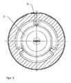
図1に示した逆止弁1は弁ハウジング2を有している。この弁ハウジング2内には、通流調整のための閉鎖エレメント3が位置している。すなわち、この閉鎖エレメント3は、媒体の逆流を不可能にし、媒体の一方向のみの通流を保証する。逆止弁1は矢印方向8への流れによって通流される。これによって、閉鎖エレメント3が、開放された位置にとどめられる。逆止弁1の流入側には、シール部分7が位置している。このシール部分7は、逆止弁1の閉鎖時にシール性を保証している。シール部分7は、異形シール部材5と、支持リング4と、螺入部材6とから形成されている。異形シール部材5は支持リング4と螺入部材6との間に不動に緊締されている。螺入部材6は弁ハウジング2内にねじ込まれていて、支持リング4が弁ハウジング2に接触するまで固く締結される。閉鎖エレメント3は、弁ハウジング2にリブ11を介して同心的に位置固定されて位置決めされた支承部10を介してガイドされる。この支承部10を弁ハウジング2に位置固定するために、理想的には、全周に沿って均等に分配された3つのリブ11が使用される。ただし、3つよりも多くのリブ11も可能であるが、この場合には、流れ抵抗が望ましくない形で高められてしまう。支承部10は当接面12を有している。この当接面12には、閉鎖エレメント3が、開放された状態で接触している。さらに、支承部10は支持面16を有している。この支持面16は、当接面12に対して僅かに凹状に引っ込められている。支持面16は、必要に応じて組込み可能であるばね15を支持するために働く。流れ方向8における媒体が滞留している場合には、閉鎖エレメント3が閉鎖位置に落下していて、媒体の逆流9を阻止している。有利には、部材がプラスチックから製造されている。しかし、別種の材料、たとえば銅、鋼、黄銅等も可能である。 The check valve 1 shown in FIG. 1 has a
支承部10を弁ハウジング2に固定するリブ11は、さらに、閉鎖エレメント3のガイド部として働く。このことは、図2に認められる。これによって、閉鎖エレメント3の移動の間の座屈が不可能になる。 The
弁ハウジング2は両端部に雄ねじ山を備えている。両雄ねじ山には、ユニオンナット20,21が螺合される。このユニオンナット20,21によって、接続部材22,23がOリング18,19に向かって押圧される。このOリング18,19は、螺入部材6の端面にもしくは出口側で弁ハウジング2の端面に位置している。螺入部材6は、弁ハウジング2に配置された雌ねじ山を介してねじ込まれる。これによって、支持リング4が異形シール部材5を介して弁ハウジング2の端面13に向かって押圧される。図3では、閉鎖エレメント3が、閉鎖された位置にある。この閉鎖エレメント3は、ゾーンB35の球形状もしくは球冠形状の球面で異形シール部材5を押圧する。この異形シール部材5を安定させるために、螺入部材6が使用される。これによって、閉鎖エレメント3に作用する圧力が過度に高い場合に異形シール部材5が撓まず、したがって、閉鎖エレメント3が滑らないようになっている。 The
図4には、ばね15が挿入された逆止弁1が示してあり、これによって、たとえば逆止弁1が水平に組み付けられている場合、それにもかかわらず、閉鎖エレメント3と異形シール部材5との間に確実な密閉が達成される。ばね15によって、閉鎖エレメント3にばね圧が加えられる。これによって、ばね15の抵抗圧を上回るために、流れ方向8に十分な圧力を発生させる流れが生じるまで、逆止弁1は閉鎖されている。このようなばね15は、閉鎖エレメント3に使用された材料が小さな比重を有していて、自重だけでは逆止弁1を十分に閉鎖することができない場合に有利に組み込むこともできる。さらに、閉鎖エレメント3に設けられたガイド部32が、支持面16に接触しているばね15のガイド部として働く。ガイド部32には、4つのガイドリブ33が配置されている。これと異なる個数のガイドリブ33も可能である。こうして、ガイド部32が全周で支承部10に接触するのではなく、ガイドリブ33を介してのみ接触し、これによって、摩擦を著しく減少させることができ、それにもかかわらず、閉鎖エレメント3が弁ハウジング2に対して同心的にガイドされる。別の形態のガイド部も可能である。 FIG. 4 shows a check valve 1 with a
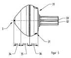
所望の流量もしくは所望の流量係数を達成すると共に一定に維持し、また、要求されたシール性を達成するためには、閉鎖エレメント3の外側輪郭が、図5に示した種々異なるゾーンから形成されている。ゾーンA34は、流れに対して最適化された外側輪郭を有している。この場合、ゾーンA34における外側輪郭は、円錐形に延びていてもよい。曲線は、逆止弁1内での抵抗が最小となり、これによって、この逆止弁1が極めて良好な流れ技術的な数値を獲得するように成形加工されている。ゾーンA34の曲線には、逆止弁1の最適な密閉のために働くゾーンB35の球形状もしくは球冠形状が続いている。両幾何学形状の並列によって、閉鎖された位置でシール性が付与されているだけでなく、逆止弁1の開放中には、ゾーンA34によって達成される最小の流れ抵抗も付与されている。ゾーンB35に続くゾーンC36では、ゾーンB35の円弧に対応している必要はない円弧が、この円弧に対して接線方向に延びていない直線に移行している。これによって、流れ案内エレメント31が形成される。この流れ案内エレメント31によって、閉鎖エレメント3の姿勢が一層安定する。すなわち、流量係数もしくは通流体積が一定に保たれる。流れ案内エレメント31の使用は渦流発生を減少させ、ひいては、閉鎖エレメント3の支持面37に作用する抵抗圧も減少させる。閉鎖エレメント3の、流れに対して最適化された曲線と、最適に密閉する球形状もしくは球冠形状と、流れ案内エレメント31とから形成された外側輪郭によって、振動が減少させられ、流量係数が一定に維持され、騒音が低減され、さらに、ばね15による逆止弁1の拡張、つまり、逆止弁1へのばね15の増設が問題なく可能となる。 In order to achieve the desired flow rate or the desired flow coefficient and to keep it constant and to achieve the required sealing properties, the outer contour of the closure element 3 is formed from different zones as shown in FIG. ing. Zone A34 has an outer contour optimized for flow. In this case, the outer contour in the zone A34 may extend conically. The curve is shaped so that the resistance in the check valve 1 is minimized, so that the check valve 1 obtains a very good flow technical value. The curve of zone A34 is followed by the sphere or crown shape of zone B35 which serves for optimal sealing of the check valve 1. The parallel arrangement of both geometries not only provides sealing in the closed position, but also provides the minimum flow resistance achieved by zone A34 during the opening of check valve 1. In the zone C36 following the zone B35, an arc that does not need to correspond to the arc of the zone B35 has shifted to a straight line that does not extend tangentially to the arc. Thereby, the
図6には、流れに対して最適化された外側輪郭の全周に沿ってゾーンA34の範囲内に複数の羽根38を有する閉鎖エレメント3の実施の形態が示してある。羽根38は全周にわたって均等に分配されている。図示の実施の形態では、閉鎖エレメント3が5つの羽根38を有している。これと異なる個数の羽根38も可能である。これらの羽根38は僅かな曲率を有している。このことは、流れ方向8に通流する媒体による回転発生時に役立つ。閉鎖エレメント3の回転の効果は、逆止弁1の自浄に利用される。回転によって、シール部分7とガイド部分14とから汚染粒子が解離される。閉鎖エレメント3は、通常のケースでは、通流する媒体内で浮遊しており、閉鎖エレメント3の回転を困難にする恐れがあるような、当接面12に接触するケースは僅かでしかないので、前述した効果が可能となる。図6に示した実施の形態では、ガイド部32がガイドリブ33を有している。このガイドリブ33は、ガイド部32の円筒状の周面に沿って螺旋状に延びている。ガイドリブ33はその螺旋状の配置によって閉鎖エレメント3の回転運動をアシストし、逆止弁1を通る汚染粒子の搬送をアシストする。ガイド部32に沿って真っ直ぐ延びるガイドリブ33と、図6に示したように、ゾーンA34の範囲内の周面に設けられた羽根38との組合せも可能である。 FIG. 6 shows an embodiment of the closure element 3 having a plurality of
1 逆止弁
2 弁ハウジング
3 閉鎖エレメント
4 支持リング
5 異形シール部材
6 螺入部材
7 シール部分
8 通流方向
9 逆流方向
10 支承部
11 リブ
12 当接面
13 端面
15 ばね
16 支持面
18 Oリング
19 Oリング
20 ユニオンナット
21 ユニオンナット
22 接続部材
23 接続部材
31 流れ案内エレメント
32 閉鎖エレメントのガイド部
33 閉鎖エレメントのガイドリブ
34 ゾーンA
35 ゾーンB
36 ゾーンC
37 閉鎖エレメントの支持面
38 羽根DESCRIPTION OF SYMBOLS 1
35 Zone B
36 Zone C
37 Closing
Claims (12)
Translated fromJapaneseApplications Claiming Priority (3)
| Application Number | Priority Date | Filing Date | Title |
|---|---|---|---|
| EP10196422.9 | 2010-12-22 | ||
| EP10196422.9AEP2469136B1 (en) | 2010-12-22 | 2010-12-22 | Check valve with optimised closing element |
| PCT/EP2011/072691WO2012084625A1 (en) | 2010-12-22 | 2011-12-14 | Check valve having an optimized closing element |
Publications (1)
| Publication Number | Publication Date |
|---|---|
| JP2014501366Atrue JP2014501366A (en) | 2014-01-20 |
Family
ID=43983589
Family Applications (1)
| Application Number | Title | Priority Date | Filing Date |
|---|---|---|---|
| JP2013545191APendingJP2014501366A (en) | 2010-12-22 | 2011-12-14 | Check valve with optimized closing element |
Country Status (10)
| Country | Link |
|---|---|
| US (1) | US20140020774A1 (en) |
| EP (1) | EP2469136B1 (en) |
| JP (1) | JP2014501366A (en) |
| KR (1) | KR20130132561A (en) |
| CN (1) | CN103403421A (en) |
| AU (1) | AU2011347798A1 (en) |
| ES (1) | ES2547274T3 (en) |
| SG (1) | SG190778A1 (en) |
| TW (1) | TW201235585A (en) |
| WO (1) | WO2012084625A1 (en) |
Cited By (2)
| Publication number | Priority date | Publication date | Assignee | Title |
|---|---|---|---|---|
| WO2016013301A1 (en)* | 2014-07-24 | 2016-01-28 | 日立オートモティブシステムズ株式会社 | High-pressure fuel pump |
| JP2018194017A (en)* | 2017-05-12 | 2018-12-06 | 株式会社テイエルブイ | Check valve |
Families Citing this family (14)
| Publication number | Priority date | Publication date | Assignee | Title |
|---|---|---|---|---|
| DE102011077252B4 (en)* | 2011-06-09 | 2018-10-04 | Robert Bosch Gmbh | Valve for controlling a fluid |
| CN103092384A (en) | 2011-11-02 | 2013-05-08 | 宸鸿科技(厦门)有限公司 | Touch panel with conductive bridge structure and manufacturing method thereof |
| EP2770208B1 (en) | 2013-02-20 | 2018-01-10 | Schukra Gerätebau GmbH | Adjusting device for a vehicle component |
| DE102014009178B4 (en)* | 2014-06-21 | 2019-05-02 | Festo Ag & Co. Kg | Check valve and thus equipped vacuum working device |
| WO2017027963A1 (en)* | 2015-08-14 | 2017-02-23 | Dana Canada Corporation | Anti-drain valve assembly with integrated fixation function |
| KR101681453B1 (en)* | 2016-06-03 | 2016-12-12 | 채희동 | Check valve with a vortex generator |
| KR102391684B1 (en)* | 2017-06-23 | 2022-04-28 | 엘지전자 주식회사 | Clothes treating apparatus |
| CN107314133A (en)* | 2017-08-22 | 2017-11-03 | 赛洛克流体设备成都有限公司 | A kind of super-pressure check valve easy to use |
| DE102018111811A1 (en)* | 2018-05-16 | 2019-11-21 | Otto Egelhof Gmbh & Co. Kg | Check valve, in particular for a refrigeration or heat cycle |
| CN112361040B (en)* | 2021-01-13 | 2021-04-16 | 潍柴动力股份有限公司 | check valve |
| PL439697A1 (en) | 2021-11-30 | 2023-06-05 | Aweco Polska Appliance Spółka Z Ograniczoną Odpowiedzialnością Spółka Komandytowa | Non-return valve, piston, especially for domestic dishwashers |
| KR102656503B1 (en)* | 2021-12-09 | 2024-04-09 | 정성권 | Angle valve |
| WO2024259365A1 (en)* | 2023-06-16 | 2024-12-19 | Wanner Engineering, Inc. | Valve with replaceable hard inserts |
| CN117489832B (en)* | 2023-10-26 | 2025-01-17 | 青岛伟隆阀门股份有限公司 | Pipeline backflow preventer and method thereof |
Family Cites Families (17)
| Publication number | Priority date | Publication date | Assignee | Title |
|---|---|---|---|---|
| US1942616A (en)* | 1931-01-26 | 1934-01-09 | James W Sandlin | Valve mechanism |
| US2143399A (en)* | 1935-05-06 | 1939-01-10 | Abercrombie Pump Company | Pump valve |
| GB1115993A (en)* | 1965-04-29 | 1968-06-06 | Belliss & Morcom Mfg Ltd | Non-return valves |
| US4201243A (en)* | 1978-12-15 | 1980-05-06 | The Drum Engineering Company Limited | Check valves |
| US4340084A (en) | 1980-08-28 | 1982-07-20 | Houdaille Industries, Inc. | Check valve |
| US4375939A (en)* | 1980-09-29 | 1983-03-08 | Carrier Corporation | Capacity-prewhirl control mechanism |
| IT1157513B (en)* | 1982-02-17 | 1987-02-18 | Bonomi Ilario & C Enol Gas | NON-RETURN VALVE WITH PERFECTED SPRING SHUTTER |
| US4535808A (en)* | 1983-07-08 | 1985-08-20 | Dicken Manufacturing Company | Check valve |
| US4813452A (en)* | 1987-09-28 | 1989-03-21 | Smith Roger R | Kinetic check valve |
| JPH0651519B2 (en)* | 1989-12-26 | 1994-07-06 | 東洋製罐株式会社 | Aseptic filling valve |
| CA2017405C (en)* | 1990-05-23 | 1995-02-21 | Kenneth Richard Mcconnell | Ball and seat-type valve for downhole rod pump |
| US5044604A (en)* | 1990-08-31 | 1991-09-03 | Topham Fred A | Valve plug having fluid directing grooves |
| US6971405B2 (en)* | 2002-10-09 | 2005-12-06 | Delphi Technologies, Inc. | Check valve for fuel pump |
| JP2004138146A (en)* | 2002-10-17 | 2004-05-13 | Univ Hiroshima | Check valve, auxiliary circulation device, and method of driving auxiliary circulation device |
| JP4418267B2 (en)* | 2004-03-17 | 2010-02-17 | 日立オートモティブシステムズ株式会社 | Check valve |
| US8453673B2 (en)* | 2009-04-22 | 2013-06-04 | Michael Brent Ford | Valve cage for a pump |
| CN101737533B (en)* | 2009-12-31 | 2012-02-08 | 广东联塑科技实业有限公司 | Water hammer-resistant mute check valve |
- 2010
- 2010-12-22ESES10196422.9Tpatent/ES2547274T3/enactiveActive
- 2010-12-22EPEP10196422.9Apatent/EP2469136B1/enactiveActive
- 2011
- 2011-10-17TWTW100137575Apatent/TW201235585A/enunknown
- 2011-12-14CNCN201180061943XApatent/CN103403421A/enactivePending
- 2011-12-14SGSG2013035860Apatent/SG190778A1/enunknown
- 2011-12-14JPJP2013545191Apatent/JP2014501366A/enactivePending
- 2011-12-14KRKR20137019447Apatent/KR20130132561A/ennot_activeCeased
- 2011-12-14AUAU2011347798Apatent/AU2011347798A1/ennot_activeAbandoned
- 2011-12-14WOPCT/EP2011/072691patent/WO2012084625A1/enactiveApplication Filing
- 2011-12-14USUS13/996,612patent/US20140020774A1/ennot_activeAbandoned
Cited By (2)
| Publication number | Priority date | Publication date | Assignee | Title |
|---|---|---|---|---|
| WO2016013301A1 (en)* | 2014-07-24 | 2016-01-28 | 日立オートモティブシステムズ株式会社 | High-pressure fuel pump |
| JP2018194017A (en)* | 2017-05-12 | 2018-12-06 | 株式会社テイエルブイ | Check valve |
Also Published As
| Publication number | Publication date |
|---|---|
| SG190778A1 (en) | 2013-07-31 |
| TW201235585A (en) | 2012-09-01 |
| KR20130132561A (en) | 2013-12-04 |
| EP2469136A1 (en) | 2012-06-27 |
| ES2547274T3 (en) | 2015-10-05 |
| US20140020774A1 (en) | 2014-01-23 |
| CN103403421A (en) | 2013-11-20 |
| EP2469136B1 (en) | 2015-08-19 |
| AU2011347798A1 (en) | 2013-06-13 |
| WO2012084625A1 (en) | 2012-06-28 |
Similar Documents
| Publication | Publication Date | Title |
|---|---|---|
| JP2014501366A (en) | Check valve with optimized closing element | |
| US9856893B2 (en) | Erosion-resistant fluid pressure reduction device | |
| US8215609B2 (en) | Flow control valve assembly with low noise | |
| JP2010091110A (en) | Butterfly valve flow controller | |
| US7581712B2 (en) | Valve | |
| US7036523B2 (en) | Serviceable check valve | |
| JP6914072B2 (en) | Ball valve | |
| JPS6213552B2 (en) | ||
| KR100993446B1 (en) | Back-flow preventing apparatus for waterworks | |
| WO1998021419A1 (en) | Flow regulator | |
| US1172739A (en) | Condenser water-valve. | |
| CN113063026A (en) | A New Labyrinth Sleeve Regulating Valve | |
| US20220186850A1 (en) | Check-valve | |
| CN110220018B (en) | One-way valve | |
| US11970845B2 (en) | Valve for controlling water flow and for improving water meter health and readings | |
| KR20090000772U (en) | Piping backflow prevention structure | |
| CN210423857U (en) | Plastic safety valve | |
| KR101595536B1 (en) | Vortex prevention apparatus | |
| US1180989A (en) | Boiler-check. | |
| KR200441924Y1 (en) | Backflow prevention connecting valve | |
| KR20230086879A (en) | Angle valve | |
| KR101098842B1 (en) | 2-stage check valve | |
| CN111911658A (en) | One-piece full-pass eccentric half-ball valve | |
| KR19980021117U (en) | Impeller Built-in Check Valve | |
| GB2461463A (en) | Ballcock diaphragm valve |