JP2014501131A - Humidifier system that humidifies the gas supplied to the patient - Google Patents
Humidifier system that humidifies the gas supplied to the patientDownload PDFInfo
- Publication number
- JP2014501131A JP2014501131AJP2013543932AJP2013543932AJP2014501131AJP 2014501131 AJP2014501131 AJP 2014501131AJP 2013543932 AJP2013543932 AJP 2013543932AJP 2013543932 AJP2013543932 AJP 2013543932AJP 2014501131 AJP2014501131 AJP 2014501131A
- Authority
- JP
- Japan
- Prior art keywords
- liquid
- patient circuit
- patient
- chamber
- aerosol chamber
- Prior art date
- Legal status (The legal status is an assumption and is not a legal conclusion. Google has not performed a legal analysis and makes no representation as to the accuracy of the status listed.)
- Granted
Links
Images


Classifications
- A—HUMAN NECESSITIES
- A61—MEDICAL OR VETERINARY SCIENCE; HYGIENE
- A61M—DEVICES FOR INTRODUCING MEDIA INTO, OR ONTO, THE BODY; DEVICES FOR TRANSDUCING BODY MEDIA OR FOR TAKING MEDIA FROM THE BODY; DEVICES FOR PRODUCING OR ENDING SLEEP OR STUPOR
- A61M16/00—Devices for influencing the respiratory system of patients by gas treatment, e.g. ventilators; Tracheal tubes
- A61M16/10—Preparation of respiratory gases or vapours
- A61M16/14—Preparation of respiratory gases or vapours by mixing different fluids, one of them being in a liquid phase
- A61M16/16—Devices to humidify the respiration air
- A—HUMAN NECESSITIES
- A61—MEDICAL OR VETERINARY SCIENCE; HYGIENE
- A61M—DEVICES FOR INTRODUCING MEDIA INTO, OR ONTO, THE BODY; DEVICES FOR TRANSDUCING BODY MEDIA OR FOR TAKING MEDIA FROM THE BODY; DEVICES FOR PRODUCING OR ENDING SLEEP OR STUPOR
- A61M11/00—Sprayers or atomisers specially adapted for therapeutic purposes
- A61M11/005—Sprayers or atomisers specially adapted for therapeutic purposes using ultrasonics
- A—HUMAN NECESSITIES
- A61—MEDICAL OR VETERINARY SCIENCE; HYGIENE
- A61M—DEVICES FOR INTRODUCING MEDIA INTO, OR ONTO, THE BODY; DEVICES FOR TRANSDUCING BODY MEDIA OR FOR TAKING MEDIA FROM THE BODY; DEVICES FOR PRODUCING OR ENDING SLEEP OR STUPOR
- A61M11/00—Sprayers or atomisers specially adapted for therapeutic purposes
- A61M11/006—Sprayers or atomisers specially adapted for therapeutic purposes operated by applying mechanical pressure to the liquid to be sprayed or atomised
- A—HUMAN NECESSITIES
- A61—MEDICAL OR VETERINARY SCIENCE; HYGIENE
- A61M—DEVICES FOR INTRODUCING MEDIA INTO, OR ONTO, THE BODY; DEVICES FOR TRANSDUCING BODY MEDIA OR FOR TAKING MEDIA FROM THE BODY; DEVICES FOR PRODUCING OR ENDING SLEEP OR STUPOR
- A61M11/00—Sprayers or atomisers specially adapted for therapeutic purposes
- A61M11/04—Sprayers or atomisers specially adapted for therapeutic purposes operated by the vapour pressure of the liquid to be sprayed or atomised
- A61M11/041—Sprayers or atomisers specially adapted for therapeutic purposes operated by the vapour pressure of the liquid to be sprayed or atomised using heaters
- A61M11/042—Sprayers or atomisers specially adapted for therapeutic purposes operated by the vapour pressure of the liquid to be sprayed or atomised using heaters electrical
- A—HUMAN NECESSITIES
- A61—MEDICAL OR VETERINARY SCIENCE; HYGIENE
- A61M—DEVICES FOR INTRODUCING MEDIA INTO, OR ONTO, THE BODY; DEVICES FOR TRANSDUCING BODY MEDIA OR FOR TAKING MEDIA FROM THE BODY; DEVICES FOR PRODUCING OR ENDING SLEEP OR STUPOR
- A61M16/00—Devices for influencing the respiratory system of patients by gas treatment, e.g. ventilators; Tracheal tubes
- A61M16/021—Devices for influencing the respiratory system of patients by gas treatment, e.g. ventilators; Tracheal tubes operated by electrical means
- A61M16/022—Control means therefor
- A61M16/024—Control means therefor including calculation means, e.g. using a processor
- A—HUMAN NECESSITIES
- A61—MEDICAL OR VETERINARY SCIENCE; HYGIENE
- A61M—DEVICES FOR INTRODUCING MEDIA INTO, OR ONTO, THE BODY; DEVICES FOR TRANSDUCING BODY MEDIA OR FOR TAKING MEDIA FROM THE BODY; DEVICES FOR PRODUCING OR ENDING SLEEP OR STUPOR
- A61M16/00—Devices for influencing the respiratory system of patients by gas treatment, e.g. ventilators; Tracheal tubes
- A61M16/10—Preparation of respiratory gases or vapours
- A61M16/1075—Preparation of respiratory gases or vapours by influencing the temperature
- A61M16/1085—Preparation of respiratory gases or vapours by influencing the temperature after being humidified or mixed with a beneficial agent
- A—HUMAN NECESSITIES
- A61—MEDICAL OR VETERINARY SCIENCE; HYGIENE
- A61M—DEVICES FOR INTRODUCING MEDIA INTO, OR ONTO, THE BODY; DEVICES FOR TRANSDUCING BODY MEDIA OR FOR TAKING MEDIA FROM THE BODY; DEVICES FOR PRODUCING OR ENDING SLEEP OR STUPOR
- A61M16/00—Devices for influencing the respiratory system of patients by gas treatment, e.g. ventilators; Tracheal tubes
- A61M16/10—Preparation of respiratory gases or vapours
- A61M16/1075—Preparation of respiratory gases or vapours by influencing the temperature
- A61M16/109—Preparation of respiratory gases or vapours by influencing the temperature the humidifying liquid or the beneficial agent
- A—HUMAN NECESSITIES
- A61—MEDICAL OR VETERINARY SCIENCE; HYGIENE
- A61M—DEVICES FOR INTRODUCING MEDIA INTO, OR ONTO, THE BODY; DEVICES FOR TRANSDUCING BODY MEDIA OR FOR TAKING MEDIA FROM THE BODY; DEVICES FOR PRODUCING OR ENDING SLEEP OR STUPOR
- A61M16/00—Devices for influencing the respiratory system of patients by gas treatment, e.g. ventilators; Tracheal tubes
- A61M16/10—Preparation of respiratory gases or vapours
- A61M16/1075—Preparation of respiratory gases or vapours by influencing the temperature
- A61M16/1095—Preparation of respiratory gases or vapours by influencing the temperature in the connecting tubes
- A—HUMAN NECESSITIES
- A61—MEDICAL OR VETERINARY SCIENCE; HYGIENE
- A61M—DEVICES FOR INTRODUCING MEDIA INTO, OR ONTO, THE BODY; DEVICES FOR TRANSDUCING BODY MEDIA OR FOR TAKING MEDIA FROM THE BODY; DEVICES FOR PRODUCING OR ENDING SLEEP OR STUPOR
- A61M16/00—Devices for influencing the respiratory system of patients by gas treatment, e.g. ventilators; Tracheal tubes
- A61M16/10—Preparation of respiratory gases or vapours
- A61M16/14—Preparation of respiratory gases or vapours by mixing different fluids, one of them being in a liquid phase
- A61M16/142—Preparation of respiratory gases or vapours by mixing different fluids, one of them being in a liquid phase with semi-permeable walls separating the liquid from the respiratory gas
- A—HUMAN NECESSITIES
- A61—MEDICAL OR VETERINARY SCIENCE; HYGIENE
- A61M—DEVICES FOR INTRODUCING MEDIA INTO, OR ONTO, THE BODY; DEVICES FOR TRANSDUCING BODY MEDIA OR FOR TAKING MEDIA FROM THE BODY; DEVICES FOR PRODUCING OR ENDING SLEEP OR STUPOR
- A61M15/00—Inhalators
- A61M15/0085—Inhalators using ultrasonics
- A—HUMAN NECESSITIES
- A61—MEDICAL OR VETERINARY SCIENCE; HYGIENE
- A61M—DEVICES FOR INTRODUCING MEDIA INTO, OR ONTO, THE BODY; DEVICES FOR TRANSDUCING BODY MEDIA OR FOR TAKING MEDIA FROM THE BODY; DEVICES FOR PRODUCING OR ENDING SLEEP OR STUPOR
- A61M16/00—Devices for influencing the respiratory system of patients by gas treatment, e.g. ventilators; Tracheal tubes
- A61M16/10—Preparation of respiratory gases or vapours
- A61M16/14—Preparation of respiratory gases or vapours by mixing different fluids, one of them being in a liquid phase
- A61M16/16—Devices to humidify the respiration air
- A61M16/161—Devices to humidify the respiration air with means for measuring the humidity
- A—HUMAN NECESSITIES
- A61—MEDICAL OR VETERINARY SCIENCE; HYGIENE
- A61M—DEVICES FOR INTRODUCING MEDIA INTO, OR ONTO, THE BODY; DEVICES FOR TRANSDUCING BODY MEDIA OR FOR TAKING MEDIA FROM THE BODY; DEVICES FOR PRODUCING OR ENDING SLEEP OR STUPOR
- A61M16/00—Devices for influencing the respiratory system of patients by gas treatment, e.g. ventilators; Tracheal tubes
- A61M16/10—Preparation of respiratory gases or vapours
- A61M16/14—Preparation of respiratory gases or vapours by mixing different fluids, one of them being in a liquid phase
- A61M16/16—Devices to humidify the respiration air
- A61M16/162—Water-reservoir filling system, e.g. automatic
- A—HUMAN NECESSITIES
- A61—MEDICAL OR VETERINARY SCIENCE; HYGIENE
- A61M—DEVICES FOR INTRODUCING MEDIA INTO, OR ONTO, THE BODY; DEVICES FOR TRANSDUCING BODY MEDIA OR FOR TAKING MEDIA FROM THE BODY; DEVICES FOR PRODUCING OR ENDING SLEEP OR STUPOR
- A61M2205/00—General characteristics of the apparatus
- A61M2205/33—Controlling, regulating or measuring
- A61M2205/3368—Temperature
- A—HUMAN NECESSITIES
- A61—MEDICAL OR VETERINARY SCIENCE; HYGIENE
- A61M—DEVICES FOR INTRODUCING MEDIA INTO, OR ONTO, THE BODY; DEVICES FOR TRANSDUCING BODY MEDIA OR FOR TAKING MEDIA FROM THE BODY; DEVICES FOR PRODUCING OR ENDING SLEEP OR STUPOR
- A61M2205/00—General characteristics of the apparatus
- A61M2205/36—General characteristics of the apparatus related to heating or cooling
- A61M2205/3653—General characteristics of the apparatus related to heating or cooling by Joule effect, i.e. electric resistance
- A—HUMAN NECESSITIES
- A61—MEDICAL OR VETERINARY SCIENCE; HYGIENE
- A61M—DEVICES FOR INTRODUCING MEDIA INTO, OR ONTO, THE BODY; DEVICES FOR TRANSDUCING BODY MEDIA OR FOR TAKING MEDIA FROM THE BODY; DEVICES FOR PRODUCING OR ENDING SLEEP OR STUPOR
- A61M2205/00—General characteristics of the apparatus
- A61M2205/75—General characteristics of the apparatus with filters
- A61M2205/7536—General characteristics of the apparatus with filters allowing gas passage, but preventing liquid passage, e.g. liquophobic, hydrophobic, water-repellent membranes
Landscapes
- Health & Medical Sciences (AREA)
- Engineering & Computer Science (AREA)
- Life Sciences & Earth Sciences (AREA)
- Animal Behavior & Ethology (AREA)
- Anesthesiology (AREA)
- Biomedical Technology (AREA)
- Heart & Thoracic Surgery (AREA)
- Hematology (AREA)
- Veterinary Medicine (AREA)
- Public Health (AREA)
- General Health & Medical Sciences (AREA)
- Pulmonology (AREA)
- Emergency Medicine (AREA)
- Mechanical Engineering (AREA)
- Air Humidification (AREA)
- Nozzles (AREA)
- Otolaryngology (AREA)
- Devices For Medical Bathing And Washing (AREA)
Abstract
Translated fromJapaneseDescription
Translated fromJapanese本発明は、エアロゾル化ミストの加熱を使用してガスの加湿を提供するシステム及び方法に関する。 The present invention relates to a system and method for providing humidification of a gas using heating of an aerosolized mist.
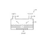
患者に供給するガスを加湿する一部の従来の方法は、チャンバを使用する。水チャンバは、加熱素子を使用して加熱される大量の水を保持する。乾いたガスは、前記チャンバにフィードされ、ここで加湿される。加湿されたガスは、前記チャンバを出て、患者回路に供給され、前記患者回路は、最終的に前記加湿されたガスを患者に供給する。図1Aは、水チャンバ101と、加熱素子103と、ガス注入口105と、排出口107とを含む水チャンバ加湿器100の一例を示す。 Some conventional methods of humidifying gas supplied to a patient use a chamber. The water chamber holds a large amount of water that is heated using a heating element. Dry gas is fed into the chamber where it is humidified. Humidified gas exits the chamber and is supplied to the patient circuit, which ultimately supplies the humidified gas to the patient. FIG. 1A shows an example of a
加湿に対する水チャンバの使用は、いくつかの欠点を引き起こす。例えば、前記水チャンバ自体は、扱いにくい可能性があり、したがって典型的には(例えばベンチレータスタンドにおける)患者から離れて配置される。このようなものとして、導管が、前記水チャンバから患者回路に加湿ガスを供給するのに使用されなければならない。この構成は、加湿器導管内で凝縮を引き起こし、加湿器を持つ患者回路において大きな抵抗及びコンプライアンスを加え、(典型的には独立した電源を必要とする)大量の電力を使用し、他の困難を引き起こす。更に、この構成は、扱いにくい水チャンバ及び大きな電力需要のため、患者移送中、家庭使用中、及び他の状況において使用するのに厄介であることができる。 The use of a water chamber for humidification causes several drawbacks. For example, the water chamber itself can be cumbersome and is therefore typically placed away from the patient (eg, in a ventilator stand). As such, a conduit must be used to supply humidified gas from the water chamber to the patient circuit. This configuration causes condensation in the humidifier conduit, adds significant resistance and compliance in the patient circuit with the humidifier, uses large amounts of power (typically requiring an independent power supply), and other difficulties cause. Furthermore, this configuration can be cumbersome to use during patient transport, home use, and other situations due to cumbersome water chambers and large power demands.
ガスを加湿する他の従来の方法は、パッシブ熱湿交換器(HME)の使用を含む。図1Bは、導管151及び親水性泡フィルタ153を含むHME150を示す。乾いたガスは、泡フィルタ153に提供されることができ、泡フィルタ153は、そこに水を含み、したがって前記ガスを加湿し、加湿されたガスが患者に提供される。HMEは、患者回路内に配置されることができるのに対し、これは、信頼できるように十分な加湿を提供しない。 Another conventional method of humidifying the gas involves the use of a passive thermal humidity exchanger (HME). FIG. 1B shows an
これら及び他の問題が存在する。 These and other problems exist.
一部の実施例において、患者に供給されるガスを加湿する加湿器システムが、提供される。前記加湿器システムは、液体源及び加湿ユニットを有することができる。前記加湿ユニットは、患者にガスを提供する患者回路に配置されることができる。前記加湿ユニットは、前記液体源から液体を受け取る液体チャンバと、前記液体チャンバからの液体を霧状にする噴霧器と、前記噴霧器からエアロゾル化液体を受け取るエアロゾルチャンバと、前記エアロゾル化液体を、前記患者回路においてガスを加湿する蒸気に変換する熱源とを有することができる。 In some embodiments, a humidifier system is provided that humidifies a gas supplied to a patient. The humidifier system can include a liquid source and a humidification unit. The humidification unit can be placed in a patient circuit that provides gas to the patient. The humidifying unit includes a liquid chamber that receives liquid from the liquid source, a nebulizer that atomizes the liquid from the liquid chamber, an aerosol chamber that receives aerosolized liquid from the nebulizer, and the aerosolized liquid to the patient. And a heat source that converts the gas to steam for humidification in the circuit.
一部の実施例において、前記加湿ユニットは、前記患者回路から前記エアロゾルチャンバを分離する疎水性膜を含み、前記疎水性膜は、液体が前記エアロゾルチャンバから前記患者回路に入ることを防ぐが、蒸気が前記エアロゾルチャンバから前記患者回路に入ることを可能にする。 In some embodiments, the humidification unit includes a hydrophobic membrane that separates the aerosol chamber from the patient circuit, the hydrophobic membrane preventing liquid from entering the patient circuit from the aerosol chamber, Allow vapor to enter the patient circuit from the aerosol chamber.
一部の実施例において、前記加湿ユニットの前記熱源は、前記エアロゾルチャンバの壁に配置される。一部の実施例において、前記加湿ユニットの前記熱源は、前記エアロゾルチャンバから前記患者回路への経路に沿った場所に配置される。一部の実施例において、前記加湿ユニットの前記熱源は、前記患者回路内に配置される。 In some embodiments, the heat source of the humidification unit is located on the wall of the aerosol chamber. In some embodiments, the heat source of the humidification unit is located at a location along the path from the aerosol chamber to the patient circuit. In some embodiments, the heat source of the humidification unit is disposed in the patient circuit.
一部の実施例において、患者に供給されるガスを加湿する方法が提供される。前記方法は、液体チャンバにおいて、液体源からの水を受け取るステップと、前記液体チャンバからの液体をエアロゾル化するステップと、前記エアロゾル化された液体をエアロゾルチャンバに供給するステップと、前記エアロゾル化された液体を蒸気にするように加熱するステップと、ガスを加湿するように患者回路に前記蒸気を供給するステップとを含むことができる。一部の実施例において、疎水性膜は、液体が前記エアロゾルチャンバから前記患者回路に入ることを防止され、前記蒸気が前記エアロゾルチャンバから前記患者回路に入ることを可能にされるように、前記患者回路から前記エアロゾルチャンバを分離する。 In some embodiments, a method for humidifying a gas supplied to a patient is provided. The method includes receiving in a liquid chamber water from a liquid source, aerosolizing the liquid from the liquid chamber, supplying the aerosolized liquid to an aerosol chamber, and the aerosolized. Heating the liquid to vapor to supply the vapor to the patient circuit to humidify the gas. In some embodiments, the hydrophobic membrane prevents liquid from entering the patient circuit from the aerosol chamber and allows the vapor to enter the patient circuit from the aerosol chamber. Separate the aerosol chamber from the patient circuit.
一部の実施例において、前記エアロゾル化液体は、前記エアロゾルチャンバの壁に配置された熱源から前記蒸気になるように加熱される。一部の実施例において、前記エアロゾル化液体は、前記エアロゾルチャンバから前記患者回路への経路に沿った場所に配置された熱源から前記蒸気に加熱される。一部の実施例において、前記エアロゾル化液体は、前記患者回路内に配置された熱源から前記蒸気になるように加熱される。 In some embodiments, the aerosolized liquid is heated to become the vapor from a heat source located on the wall of the aerosol chamber. In some embodiments, the aerosolized liquid is heated to the vapor from a heat source located at a location along the path from the aerosol chamber to the patient circuit. In some embodiments, the aerosolized liquid is heated to become the vapor from a heat source disposed in the patient circuit.
一部の実施例において、患者に供給されるガスを加湿する加湿器システムが、提供されることができる。前記加湿システムは、液体を蓄える液体源手段と、患者にガスを供給する患者回路に配置された加湿手段とを有することができる。前記加湿手段は、前記液体源手段から液体を受け取る液体チャンバ手段と、前記液体チャンバ手段からの液体を霧状にする噴霧手段と、前記噴霧手段からのエアロゾル化液体を受け取るエアロゾルチャンバ手段と、前記エアロゾル化液体を、前記患者回路においてガスを加湿する蒸気に変換する熱源手段とを有する。 In some examples, a humidifier system that humidifies the gas supplied to the patient can be provided. The humidification system may comprise liquid source means for storing liquid and humidification means disposed in a patient circuit for supplying gas to the patient. The humidifying means comprises: liquid chamber means for receiving liquid from the liquid source means; spray means for atomizing liquid from the liquid chamber means; aerosol chamber means for receiving aerosolized liquid from the spray means; Heat source means for converting the aerosolized liquid into vapor that humidifies the gas in the patient circuit.
一部の実施例において、前記加湿手段は、液体が前記エアロゾルチャンバ手段から前記患者回路に入ることを防がれるが、蒸気が前記エアロゾルチャンバ手段から前記患者回路に入ることを可能にされるように、前記患者回路から前記エアロゾルチャンバ手段を分離する膜手段を更に含む。 In some embodiments, the humidification means prevents liquid from entering the patient circuit from the aerosol chamber means, but allows vapor to enter the patient circuit from the aerosol chamber means. And further includes membrane means for separating the aerosol chamber means from the patient circuit.
一部の実施例において、前記加湿手段の前記熱源は、前記エアロゾルチャンバ手段の壁に配置される。一部の実施例において、前記加湿手段の前記熱源は、前記エアロゾルチャンバ手段から前記患者回路への経路に沿った場所に配置される。一部の実施例において、前記加湿手段の前記熱源は、前記患者回路内に配置される。 In some embodiments, the heat source of the humidifying means is located on the wall of the aerosol chamber means. In some embodiments, the heat source of the humidifying means is located at a location along the path from the aerosol chamber means to the patient circuit. In some embodiments, the heat source of the humidifying means is disposed in the patient circuit.
本開示のこれら及び他の目的、フィーチャ及び特徴、並びに動作の方法及び構造の関連する要素の機能及び部品の組み合わせ及び製造の経済性は、添付の図面を参照して以下の記載及び添付の請求項を検討すると、より明らかになり、全ての図面は、この明細書の一部を形成し、同様の参照番号は、様々な図において対応する部分を示す。一実施例において、ここに示される構造的構成要素は、一定の縮尺で描かれている。しかしながら、図面が例示及び説明の目的のみであり、限定ではないと、明らかに理解されるべきである。加えて、ここでいずれかの実施例に示される又は記載される構造的フィーチャが、他の実施例でも同様に使用されることができると理解されるべきである。しかしながら、図面が例示及び説明の目的のみであり、限定の定義として意図されないと明らかに理解されるべきである。明細書及び請求項において使用される、"ある"及び"その"の単数形は、他に明らかに指示されない限り、複数形を含む。 These and other objects, features and characteristics of the present disclosure, as well as the function of the relevant elements of the method and structure of operation and the economics of the combination of parts and manufacturing, will be described below with reference to the accompanying drawings and the appended claims. Examining the sections makes it clearer, all drawings form part of this specification, and like reference numerals indicate corresponding parts in the various figures. In one embodiment, the structural components shown herein are drawn to scale. However, it should be clearly understood that the drawings are for purposes of illustration and description only and are not limiting. In addition, it should be understood that the structural features shown or described in any of the embodiments herein can be used in other embodiments as well. However, it should be clearly understood that the drawings are for purposes of illustration and description only and are not intended as a definition of limitation. As used in the specification and claims, the singular forms “a” and “the” include the plural unless the context clearly dictates otherwise.
ここに記載される実施例は、一部の従来の加湿器と比較して減少された電力消費で患者に対するガスの加湿を可能にすることができる。更に、ここに記載される実施例は、加湿器導管又は患者回路における凝縮又は水を除去することができる。ここに記載される実施例は、減少された電力消費で、患者移送中の使用、ベンチレータシステムとの一体化、NICU(新生児集中治療室)における使用及び家庭応用を可能にする、及び/又は他の利点を提供する、小さくコンパクトな軽量設計を持つ加湿器を提供することができる。 The embodiments described herein can enable humidification of the gas to the patient with reduced power consumption compared to some conventional humidifiers. Further, the embodiments described herein can remove condensation or water in the humidifier conduit or patient circuit. The embodiments described herein enable reduced power consumption, use during patient transfer, integration with ventilator systems, use in NICU (neonatal intensive care units) and home applications, and / or others It is possible to provide a humidifier with a small, compact and lightweight design that provides the advantages of:
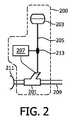
図2は、患者に加湿ガスを提供する加湿器システムの一例である加湿器システム200を示す。一部の実施例において、加湿器システム200は、加湿ユニット201、液体源203、供給部分205、コントローラ207、及び/又は他の要素を含む。 FIG. 2 shows a
加湿ユニット201は、患者インタフェース211を介して患者に加湿ガスを供給する患者回路209に沿って配置されることができる。一部の実施例において、加湿ユニット201は、患者回路209に沿って患者インタフェース211の近位に配置されることができる。例えば、一部の実施例において、加湿ユニット201は、患者回路209において、患者インタフェース211から6ないし8インチに配置されることができる。一部の実施例において、加湿ユニット201は、非侵襲的換気に使用されるマスク又は他の患者インタフェース211の屈曲部に配置されることができる。他の距離及び/又は配置が、使用されることができる。ベンチレータカートに取り付けられた従来の加湿器は、典型的には、患者から4ないし6フィート離れて配置される。この距離は、前記ベンチレータを患者回路に接続する導管における凝縮を引き起こすことができ、これは、不十分な加湿ガスを生じることができる。例えば、ワイヤ加熱導管のようなこの問題の解決法は、付加的な複雑さ及びシステムに対する電力需要を導入し、患者に供給されるガスの湿度及び温度に不利に影響を与えることもありうる。 The
患者回路209は、前記患者の呼吸器系に対する導入のために前記患者に向けたガスの流れを作るシステムを含む又はその一部であることができる。例えば、一部の実施例において、患者回路209は、ベンチレータシステム(図示されない)の一部であることができる。患者回路209の患者インタフェース211は、鼻及び/又は口マスク、鼻カニューレ、侵襲チューブ、及び/又は患者の呼吸器系に対する他のインタフェースを含むことができる。 The
液体源203は、エアロゾル化されることができ、患者の呼吸器系に提供されるべきガスを加湿するのに適した流体のコンテナ(例えば、バッグ、缶容器等)を含むことができる。一部の実施例において、前記液体は、水であることができる。一部の実施例において、前記液体は、1つ又は複数の添加物を含む水であることができ、又はエアロゾル化されることができ、患者に供給されるべきガスを加湿するのに適したいかなる流体であることもできる。一部の実施例において、液体源203は、液体源203から加湿ユニット201に流体を移送することができる可撓性管又は他の導管である又は含むことができる供給部分205を介して加湿ユニット201に接続される。水は、重力フィード、ポンプ(図示されない)又は気道内圧より上の圧力を維持する他の方法により加湿ユニット201に供給されることができる。 The
加湿システム200は、液体源203から加湿ユニット201への液体の流れを制御するために供給管に沿って又はシステム200内の他の場所に配置された弁213(例えば、ピンチ弁)をも含むことができる。加えて、1つ又は複数のセンサ(例えば、温度センサ、湿度センサ、流れセンサ、及び/又は他のセンサ)が、システム200の一部である又はシステム200とともに使用されることができる。 The
コントローラ207は、加湿器システム200の1つ又は複数の態様を制御する電子及び/又はコンピュータ実施装置を含むことができる。一部の実施例において、コントローラ107は、1つ又は複数のマイクロプロセッサ、関連したメモリ、及び/又は熱源の制御、噴霧器の制御、弁の制御、センサからのデータの受信、ユーザからの命令/データの受信、計算/決定の実行、及び/又は他のタスクを含む様々な計算タスクを実行する他のコンピュータコンポーネントを含むことができる。前記コントローラの1つ又は複数のプロセッサは、ここに記載されるようにガスを加湿するプロセッサ実行可能命令を有する1つ又は複数のモジュールを使用してプログラムされることができる。一部の実施例において、コントローラ207は、他のフィーチャを提供する装置(例えば、ベンチレータ)のコントローラの一部である、又は他の形で関連することができる。 The
加湿器システム200が、コントローラ、噴霧器、熱源、弁、センサ、ポンプ、又は加湿器システム200の他の構成要素の動作に必要な電源(例えば、バッテリ、AC接続)を含む又は接続可能であることができることは、当業者に理解される。 The
図3Aは、加湿システム200において使用されることができる加湿ユニットの一例である加湿ユニット201aの断面を示す。一部の実施例において、加湿ユニット201aは、供給管205の一部であることができる又は接続することができる若しくは他の形で液体源203に接続することができる液体注入口301を含むことができる。加湿ユニット201aは、液体注入口301から液体を受け取る液体チャンバ303をも含むことができる。一部の実施例において、液体は、ドリップワイズ(drip-wise)接続を介して滴で液体チャンバに入ることができる。他の接続及び流れタイプも、使用されることができる。加湿ユニット201aは、液体チャンバ303からエアロゾルチャンバ307内に液体を噴霧する噴霧器305をも含むことができる。一部の実施例において、噴霧器305は、振動素子(例えば、圧電素子又は圧電素子により駆動される超音波ホーン)に接続される1つ又は複数の小さな孔(例えば平均2μmまで)を持つ開口板又はメッシュを含むことができる。前記振動素子の振動は、前記メッシュ又は開口板に振動させ、これは、液体に前記孔を通ってエアロゾルチャンバ307に移動させ、前記液体をエアロゾル化粒子に変換する(すなわち、前記液体を霧状にする)。一部の実施例において、前記振動素子は、圧電素子を含むことができる。一部の実施例において、前記圧電素子は、孔を持つ開口板を有することができる。一部の実施例において、噴霧器305は、液体チャンバ内の液体を霧状にし、エアロゾルチャンバ307内に押し出すように開口部を通って押し出す圧力ベースの噴霧器を含むことができる。 FIG. 3A shows a cross section of a
一部の実施例において、液体チャンバ303は、凹形又はボウル形底部又は床を含むことができる。噴霧器305は、液体チャンバ303内に導入された液体が噴霧器に向けて流し込まれるようにこの床の底に配置されることができる。液体チャンバは、液体注入口301を含む上面カバーを含むこともできるが、他の形で周囲環境から液体チャンバ303を密封することができる。一部の実施例において、他の構成が使用されることができる。 In some examples, the
加湿ユニット201aは、エアロゾルチャンバ307内に配置され、エアロゾルチャンバ307内のエアロゾル化液体をガス/蒸気(例えば、水蒸気)に変換することができるヒータ309aをも含むことができる。エアロゾル化液体を蒸気に変換するためには、非エアロゾル化液体を蒸気に変換するのに必要である電力消費より少ない電力消費が、必要とされうる。エアロゾル化粒子の空気動力学的中央粒子径(MMAD)は、典型的には、1μmないし5μmの範囲である。ヒータ309aは、例えば、PTC(正温度係数)セラミックヒータ素子、絶縁エッチングホイルヒータ、絶縁巻線ヒータ、カーボンファイバヒータ、又は医療応用で使用するのに適した他の加熱素子であることができる。ヒータ309a及び/又は噴霧部305は、電力を提供するワイヤ又は他のコネクタ及び/又はコントローラ207に対する動作可能接続であることができるコネクタ311を含むことができる。一部の実施例において、エアロゾルチャンバ307は、円筒形チャンバであることができる(図3A−Cは円筒を縦方向に通る断面を示す)。しかしながら、他の構成が使用されてもよい。図3Aに示されるように、ヒータ309aは、エアロゾルチャンバ307の壁に並び、したがって前記エアロゾル化液体を取り囲むことができる。一部の実施例において、ヒータ309aは、エアロゾル化液体を蒸気に変換するのに十分な熱を提供することができる1つ又は複数の不連続パネル又は素子を含むことができる。 The
加湿ユニット201aは、患者回路209からエアロゾルチャンバ307を分離することができる膜313を含むことができる。一部の実施例において、膜313は、液体に不透過性であるが蒸気に透過性である疎水性膜(例えば、ポリテトラフルオロエチレン(PTFE)ベース材料を使用して作られる膜)を有することができる。このようなものとして、(エアロゾル化された水を含む)液体は、エアロゾルチャンバ307から患者回路209に入ることができないが、蒸発した液体は、入ることができ、これにより患者回路209内のガスを加湿する。 The
図3Bは、加湿システム200で使用されることができる加湿ユニットの一例である加湿ユニット201bの断面を示す。加湿ユニット201bは、液体注入口301、液体チャンバ303、噴霧部305、エアロゾルチャンバ307、コネクタ311、及び膜313を含む。加湿ユニット201bは、エアロゾルチャンバ307において噴霧器305と膜313との間に配置されることができるヒータ309bを含むこともできる。ヒータ309bは、液体チャンバ303と患者回路209との間のエアロゾルチャンバ307内の経路に沿った場所に配置されることができる。このようなものとして、ヒータ309bは、一般に、この経路に沿った流れを妨害しうる。しかしながら、ヒータ309bは、エアロゾル化液体が通過することを可能にすることができる多孔性素子(例えば、セラミック又はカーボンファイバ加熱素子)である又は含むことができる。このようなものとして、ヒータ309bは、エアロゾル化液体がヒータ309bの孔を通過すると(又はその直前に)エアロゾル化液体を加熱し、蒸気に変換する。 FIG. 3B shows a cross section of a
図3Cは、加湿システム200で使用されることができる加湿ユニットの一例である加湿ユニット201cの断面を示す。加湿ユニット201cは、液体注入口301、液体チャンバ303、噴霧部305、エアロゾルチャンバ307、及びコネクタ311を含む。加湿ユニット201cは、患者回路209内に配置された加熱素子315をも含むことができる。加熱素子315は、患者回路209の中に配置されるワイヤ又は他の熱発生素子であることができる。一部の実施例において、加湿ユニット201cは、患者インタフェース211から離れて、関連したベンチレータユニットの近くに配置されることができる(すなわち、前記患者インタフェースの近くに配置されなくてもよい)。更に、一部の実施例において、加湿ユニット201cは、膜を含まなくてもよい。したがって、エアロゾル化液体は、前記患者から離れたベンチレータに近い場所における患者回路209に自由に入ることができ、ここで、加熱素子315からの熱により蒸気に変換される。加熱素子は、コネクタ317によりコントローラ207及び/又は電源に接続されることができる。加湿ユニット201cは、加熱素子315からの熱が前記患者に対して十分に加熱及び加湿されたガスを提供するように前記患者インタフェースから更に離れて配置されてもよい。 FIG. 3C shows a cross section of a
図4は、患者に供給するガスを加湿するプロセスの一例であるプロセス400を示す。プロセスは、液体が液体源(例えば、液体源203)から液体チャンバ(例えば、液体チャンバ303)内に受け取られる動作401を含む。動作403において、前記液体チャンバ内の液体は、(例えば、噴霧器305を使用して)エアロゾル化され、エアロゾルチャンバ(例えば、エアロゾルチャンバ307)に供給される。動作405において、前記エアロゾル化液体は、(例えば、熱源309a、309b、加熱素子315、加熱されたガスを使用して)蒸気になるように加熱されることができる。動作407において、前記蒸気は、患者回路内のガスを加湿するように患者回路(例えば、患者回路209)に供給されることができる。ここに記載されるように、一部の例において、前記エアロゾル化液体は、前記患者回路において加熱され、蒸気に変換されることができる。 FIG. 4 shows a
ここで論じられるように、近位配置加湿器での加湿に対するエアロゾル化液体の使用は、液体を蒸発させるためのより少ない電力使用、コンパクト及び効率的設計、(より少量の液体が必要とされるので)より速い応答速度、及び/又は他の利益を含むいくつかの利益を提供する。更に、ここに記載された実施例は、患者回路において最小のコンプライアンス、抵抗及び死腔を加える。表1は、ここに記載されたエアロゾル化近位加湿器と比較した代表的なパッシブ熱湿交換器(HME)及び代表的な従来の水チャンバ加湿器の比較抵抗又は圧力降下及びコンプライアンス又は体積を示す。
ここに記載される実施例は、侵襲的換気、非侵襲的換気、高流量酸素治療、新生児CPAP(持続的気道陽圧法)、(例えば、大人の無呼吸に対する)家庭CPAP、高頻度換気及び/又は他の治療/使用を含む、家庭又は病院使用に対するガスの加湿及び加熱を必要とする様々な治療に対して使用されることができる。一部の実施例において、加湿器システム100は、大人、子ども又は新生児加湿をサポートするように様々な管サイズ(例えば、22mm、15mm、10mm又は他のサイズ)を持つ患者回路とともに使用されることができる。一部の実施例において、加湿器システム100(又はここに記載された様々な加湿ユニット)は、独立した加熱及び加湿制御ユニットを持つスタンドアロン加湿器として使用されることができる。一部の実施例において、加湿器システム100(又はここに記載された様々な加湿ユニット)は、他のシステム(例えば、ベンチレータ)と一体化されることができ、一体化された電力、制御、アラーム及び/又は他のフィーチャを可能にする。 Examples described herein include invasive ventilation, non-invasive ventilation, high flow oxygen therapy, neonatal CPAP (continuous positive airway pressure), home CPAP (eg for adult apnea), high frequency ventilation and / or Or it can be used for various treatments that require humidification and heating of gas for home or hospital use, including other treatments / uses. In some embodiments, the
ここに記載されたシステム及び方法は、例としてのみ提供される。当業者は、ここに記載されたシステムが、様々なシステム構成で機能することができることを理解する。したがって、より多い又は少ない前述のシステム構成要素が、様々な実施例において使用される及び/又は組み合わせられることができる。ここに記載された機能を達成するのに使用されるソフトウェアモジュールが、ここに記載されたもの以外の構成要素に保持されることができることも理解されるべきである。一部の実施例において、理解されるように、ここに記載された機能は、ソフトウェアに加えて又は代わりにハードウェア及び/又はファームウェアの様々な組み合わせで実施されることができる。ここに記載されたプロセスは、より多い又は少ない記載された動作を使用することができ、動作の順序は、理解されるように変更されることができる。 The systems and methods described herein are provided as examples only. Those skilled in the art will appreciate that the system described herein can function in a variety of system configurations. Accordingly, more or fewer of the aforementioned system components can be used and / or combined in various embodiments. It should also be understood that software modules used to accomplish the functions described herein may be held in components other than those described herein. In some embodiments, as will be appreciated, the functions described herein may be implemented with various combinations of hardware and / or firmware in addition to or instead of software. The processes described herein can use more or fewer described operations, and the order of operations can be changed as understood.
実施例は、1つ又は複数のプロセッサに、ここに記載されたフィーチャ及び機能の一部又は全てを実行させる/実行するように構成/命令するコンピュータ実行可能命令を持つ持続性コンピュータ可読媒体(例えば、ディスク、メモリスティック、ハードディスク、又は他の揮発性若しくは不揮発性記憶媒体)を更に含む。 An example embodiment is a persistent computer readable medium having computer-executable instructions configured / instructed to cause / activate one or more processors to perform / execute some or all of the features and functions described herein (eg, , Disk, memory stick, hard disk, or other volatile or non-volatile storage medium).
ここに含まれる詳細は、何が現在最も実際的かつ好適な実施例であるとみなされるかに基づく説明の目的であり、このような詳細が、当該目的のみであり、この明細書の範囲が開示された実施例に限定されないが、逆に、添付の請求項の範囲及び精神内である修正例及び同等の構成をカバーすることを意図されると理解されるべきである。例えば、本開示が、可能な限り、いかなる実施例の1つ又は複数のフィーチャも、いかなる他の実施例の1つ又は複数のフィーチャと組み合わせられることができることを意図すると理解されるべきである。 The details contained herein are for illustrative purposes based on what is presently considered to be the most practical and preferred embodiment, and such details are solely for that purpose and the scope of this specification is It should be understood that the invention is not limited to the disclosed embodiments, but on the contrary is intended to cover modifications and equivalent arrangements that are within the scope and spirit of the appended claims. For example, it should be understood that the present disclosure contemplates that, to the extent possible, one or more features of any embodiment can be combined with one or more features of any other embodiment.
Claims (15)
Translated fromJapanese液体源と、
患者にガスを供給する患者回路に配置された加湿ユニットであって、
前記液体源から液体を受け取る液体チャンバ、
前記液体チャンバからの液体を霧状にする噴霧器、
前記噴霧器からエアロゾル化液体を受け取るエアロゾルチャンバ、及び
前記エアロゾル化液体を、前記患者回路内のガスを加湿する蒸気に変換する熱源、
を有する当該加湿ユニットと、
を有するシステム。In a humidifier system that humidifies the gas supplied to the patient,
A liquid source;
A humidifying unit arranged in a patient circuit for supplying gas to a patient,
A liquid chamber for receiving liquid from the liquid source;
A nebulizer for atomizing the liquid from the liquid chamber;
An aerosol chamber that receives aerosolized liquid from the nebulizer; and a heat source that converts the aerosolized liquid into vapor that humidifies the gas in the patient circuit;
The humidifying unit having
Having a system.
液体チャンバにおいて、液体源からの水を受け取るステップと、
前記液体チャンバからの液体をエアロゾル化するステップと、
前記エアロゾル化液体をエアロゾルチャンバに供給するステップと、
前記エアロゾル化液体を蒸気にするように加熱するステップと、
ガスを加湿するように患者回路に前記蒸気を供給するステップと、
を有する方法。In a method of humidifying a gas supplied to a patient,
Receiving in a liquid chamber water from a liquid source;
Aerosolizing the liquid from the liquid chamber;
Supplying the aerosolized liquid to an aerosol chamber;
Heating the aerosolized liquid to vapor;
Supplying the vapor to a patient circuit to humidify the gas;
Having a method.
液体を蓄える液体源手段と、
患者にガスを供給する患者回路に配置された加湿手段であって、
前記液体源手段から液体を受け取る液体チャンバ手段、
前記液体チャンバ手段からの液体を霧状にする噴霧手段、
前記噴霧手段からのエアロゾル化液体を受け取るエアロゾルチャンバ手段、及び
前記エアロゾル化液体を、前記患者回路におけるガスを加湿する蒸気に変換する熱源手段、
を有する当該加湿手段と、
を有するシステム。In a humidifier system that humidifies the gas supplied to the patient,
A liquid source means for storing the liquid;
A humidifying means arranged in a patient circuit for supplying gas to the patient,
Liquid chamber means for receiving liquid from said liquid source means;
Spraying means for atomizing the liquid from the liquid chamber means;
Aerosol chamber means for receiving aerosolized liquid from the spraying means; and heat source means for converting the aerosolized liquid into vapor for humidifying gas in the patient circuit;
Said humidifying means comprising:
Having a system.
Applications Claiming Priority (3)
| Application Number | Priority Date | Filing Date | Title |
|---|---|---|---|
| US201061424347P | 2010-12-17 | 2010-12-17 | |
| US61/424,347 | 2010-12-17 | ||
| PCT/IB2011/055586WO2012080923A1 (en) | 2010-12-17 | 2011-12-09 | A humidifier system for humidifying gas delivered to a patient |
Publications (3)
| Publication Number | Publication Date |
|---|---|
| JP2014501131Atrue JP2014501131A (en) | 2014-01-20 |
| JP2014501131A5 JP2014501131A5 (en) | 2015-02-05 |
| JP6297332B2 JP6297332B2 (en) | 2018-03-20 |
Family
ID=45531895
Family Applications (1)
| Application Number | Title | Priority Date | Filing Date |
|---|---|---|---|
| JP2013543932AExpired - Fee RelatedJP6297332B2 (en) | 2010-12-17 | 2011-12-09 | Humidifier system that humidifies the gas supplied to the patient |
Country Status (8)
| Country | Link |
|---|---|
| US (1) | US9375548B2 (en) |
| EP (1) | EP2651482B1 (en) |
| JP (1) | JP6297332B2 (en) |
| CN (1) | CN103260686B (en) |
| BR (1) | BR112013014795A8 (en) |
| RU (1) | RU2594241C2 (en) |
| TR (1) | TR201910722T4 (en) |
| WO (1) | WO2012080923A1 (en) |
Cited By (4)
| Publication number | Priority date | Publication date | Assignee | Title |
|---|---|---|---|---|
| JP2017522154A (en)* | 2014-06-25 | 2017-08-10 | アウトスタンディング ヘルスケア カンパニー リミテッド | Micro humidifier |
| WO2017179569A1 (en)* | 2016-04-13 | 2017-10-19 | 株式会社メトラン | Humidifier and respiratory aid device |
| WO2018002989A1 (en)* | 2016-06-27 | 2018-01-04 | 日本たばこ産業株式会社 | Flavor inhaler cartridge and flavor inhaler having flavor inhaler cartridge |
| JP2021507777A (en)* | 2017-12-29 | 2021-02-25 | コーニンクレッカ フィリップス エヌ ヴェKoninklijke Philips N.V. | Humidifier and airway pressure assist system including it |
Families Citing this family (32)
| Publication number | Priority date | Publication date | Assignee | Title |
|---|---|---|---|---|
| EP2667919B1 (en) | 2011-01-24 | 2021-05-26 | ResMed Pty Ltd | Humidifier |
| US9629566B2 (en) | 2011-03-11 | 2017-04-25 | Spacelabs Healthcare Llc | Methods and systems to determine multi-parameter managed alarm hierarchy during patient monitoring |
| GB201114580D0 (en)* | 2011-08-23 | 2011-10-05 | Armstrong Medical Ltd | Humidified gas delivery system |
| US20130228177A1 (en)* | 2012-03-01 | 2013-09-05 | Gerald Schueller | Cpap humidifier tank control valve |
| US20150083126A1 (en)* | 2012-04-27 | 2015-03-26 | Draeger Medical Systems, Inc. | Breathing Circuit Humidification System |
| US10155098B2 (en)* | 2012-06-25 | 2018-12-18 | Fisher & Paykel Healthcare Limited | Medical components with microstructures for humidification and condensate management |
| EP3909633B1 (en)* | 2013-03-14 | 2023-11-22 | Fisher & Paykel Healthcare Limited | Humidification chamber with a mixing element comprising microstructures |
| US10987026B2 (en) | 2013-05-30 | 2021-04-27 | Spacelabs Healthcare Llc | Capnography module with automatic switching between mainstream and sidestream monitoring |
| WO2016028525A1 (en)* | 2014-08-18 | 2016-02-25 | Hancock Medical, Inc. | Portable pap device with humidification |
| CA3175751A1 (en)* | 2014-09-03 | 2016-03-10 | Fisher & Paykel Healthcare Limited | Deterministically controlled humidification system |
| US9649468B2 (en) | 2014-09-03 | 2017-05-16 | Fisher & Paykel Healthcare Limited | Respiratory gas humidifier |
| CN105498062A (en)* | 2014-10-09 | 2016-04-20 | 台达电子工业股份有限公司 | Humidifying device for breathing mask |
| CN106178219B (en)* | 2015-04-30 | 2018-06-15 | 小牛科技河北有限公司 | A kind of humidification machine of lung ventilator |
| DE102015119523B4 (en)* | 2015-11-12 | 2024-02-22 | Wilamed Gmbh | Ventilation circuit |
| EP3386578B1 (en) | 2015-12-11 | 2023-01-25 | Fisher & Paykel Healthcare Limited | Humidification system |
| EP3457926A4 (en) | 2016-05-19 | 2020-09-09 | Hancock Medical, Inc. | SYSTEM FOR DETECTING POSITIONAL OBSTRUCTIVE SLEEP APNEA |
| WO2018035579A1 (en) | 2016-08-26 | 2018-03-01 | Resmed Limited | Respiratory pressure therapy system with nebulising humidifier |
| WO2018081272A1 (en)* | 2016-10-26 | 2018-05-03 | Teleflex Medical Incorporated | System and method for on-demand near-patient humidification |
| WO2018109095A1 (en)* | 2016-12-14 | 2018-06-21 | Koninklijke Philips N.V. | Humidification of a pressurized flow of breathable gas |
| US11534569B2 (en)* | 2017-05-31 | 2022-12-27 | Virginia Commonwealth University | Combination devices, systems, and methods for humidification of the airways and high efficiency delivery of pharmaceutical aerosols |
| CN107174718B (en)* | 2017-06-21 | 2024-05-24 | 湖南明康中锦医疗科技发展有限公司 | Breathing machine humidifier and breathing humidification treatment device |
| EP4173664A3 (en) | 2017-07-10 | 2023-05-31 | Medline Industries, LP | Moisture removal and condensation and humidity management apparatus for a breathing circuit |
| US11156218B2 (en)* | 2017-12-29 | 2021-10-26 | Koninklijke Philips N.V. | Humidifier and airway pressure support system including same |
| EP3793653B1 (en) | 2018-05-14 | 2023-10-25 | Covidien LP | Systems and methods for ventilation humidification |
| CN118902469A (en) | 2019-06-26 | 2024-11-08 | 太空实验室健康护理有限公司 | Modifying monitored physiological data using data of body worn sensors |
| EP4051351A1 (en)* | 2019-10-31 | 2022-09-07 | ResMed Sensor Technologies Limited | Systems and methods for injecting substances into a respiratory system |
| CA3175946A1 (en) | 2020-05-21 | 2021-11-25 | Good News Medical Co., Ltd. | Device for alleviating obstructive sleep apnea |
| US12427282B2 (en) | 2020-09-09 | 2025-09-30 | Covidien Lp | Systems and methods for active humidification in ventilatory support |
| WO2022119790A1 (en)* | 2020-12-01 | 2022-06-09 | The Government Of The United States, As Represented By The Secretary Of The Army | Thermogenic airway management device and methods |
| CN116115864A (en)* | 2021-11-15 | 2023-05-16 | 深圳麦克韦尔科技有限公司 | Atomizing device |
| US20230191068A1 (en)* | 2021-12-22 | 2023-06-22 | Covidien Lp | Vaporization configurations for breathing gases humidifier |
| EP4260893B1 (en) | 2022-04-14 | 2024-10-30 | Sedana Medical Limited | Active humidification device |
Citations (3)
| Publication number | Priority date | Publication date | Assignee | Title |
|---|---|---|---|---|
| JP2000500988A (en)* | 1995-08-28 | 2000-02-02 | ポンヌ,ジルマン エ アントニー ボフ | Heated respiratory therapy humidifier |
| WO2009037863A1 (en)* | 2007-09-21 | 2009-03-26 | Metran Co., Ltd. | Medical treatment gas humidifier, medical treatment gas humidifier/transporting system, and artificial respirator system |
| US20090241948A1 (en)* | 2007-03-28 | 2009-10-01 | Dermot Joseph Clancy | Humidification in breathing circuits |
Family Cites Families (14)
| Publication number | Priority date | Publication date | Assignee | Title |
|---|---|---|---|---|
| US3949743A (en) | 1973-03-19 | 1976-04-13 | Schick Incorporated | Medicated vapor production method and apparatus |
| GB1490974A (en) | 1973-11-12 | 1977-11-09 | Fodor I | Air humidifiers |
| DE2702674C3 (en) | 1977-01-24 | 1981-02-12 | Draegerwerk Ag, 2400 Luebeck | Respiratory gas humidifier |
| US4921642A (en) | 1987-12-03 | 1990-05-01 | Puritan-Bennett Corporation | Humidifier module for use in a gas humidification assembly |
| DE4312793C2 (en) | 1993-04-20 | 1995-04-27 | Devilbiss Medizinische Produkt | Device for providing warm humidified breathing gas |
| DE19621541C1 (en) | 1996-05-29 | 1997-04-10 | Draegerwerk Ag | Respirator machine humidifier with hollow fibre membrane |
| JPH1028737A (en) | 1996-07-16 | 1998-02-03 | Metoran:Kk | Humidification adjustment unit, humidifier for ventilator, and method of manufacturing humidification adjustment unit |
| SE9902627D0 (en) | 1999-07-08 | 1999-07-08 | Siemens Elema Ab | Medical nebulizer |
| US6978779B2 (en)* | 2002-04-19 | 2005-12-27 | Instrumentarium Corp. | Vibrating element liquid discharging apparatus having gas pressure sensing |
| US7073500B2 (en) | 2003-05-23 | 2006-07-11 | Lawrence Kates | Method and apparatus for defending against naso-pharyngeal viral attacks |
| US8944056B2 (en)* | 2007-02-09 | 2015-02-03 | Resmed Limited | Humidification arrangement for a respiratory apparatus |
| WO2009118718A1 (en)* | 2008-03-28 | 2009-10-01 | Stamford Devices Limited | Ηumidification in breathin circuits |
| RU83187U1 (en)* | 2008-07-07 | 2009-05-27 | Государственное образовательное учреждение высшего профессионального образования "Омская государственная медицинская академия Федерального агентства по здравоохранению и социальному развитию" Росздрава | DEVICE FOR RESPIRATORY SUPPORT FOR PATIENTS WITH SEVERE CRANIO-BRAIN INJURY |
| WO2010035251A2 (en) | 2008-09-26 | 2010-04-01 | Stamford Devices Limited | A supplemental oxygen delivery system |
- 2011
- 2011-12-09RURU2013132946/14Apatent/RU2594241C2/ennot_activeIP Right Cessation
- 2011-12-09BRBR112013014795Apatent/BR112013014795A8/ennot_activeApplication Discontinuation
- 2011-12-09USUS13/993,133patent/US9375548B2/ennot_activeExpired - Fee Related
- 2011-12-09TRTR2019/10722Tpatent/TR201910722T4/enunknown
- 2011-12-09JPJP2013543932Apatent/JP6297332B2/ennot_activeExpired - Fee Related
- 2011-12-09WOPCT/IB2011/055586patent/WO2012080923A1/enactiveApplication Filing
- 2011-12-09CNCN201180060784.1Apatent/CN103260686B/ennot_activeExpired - Fee Related
- 2011-12-09EPEP11813562.3Apatent/EP2651482B1/ennot_activeNot-in-force
Patent Citations (3)
| Publication number | Priority date | Publication date | Assignee | Title |
|---|---|---|---|---|
| JP2000500988A (en)* | 1995-08-28 | 2000-02-02 | ポンヌ,ジルマン エ アントニー ボフ | Heated respiratory therapy humidifier |
| US20090241948A1 (en)* | 2007-03-28 | 2009-10-01 | Dermot Joseph Clancy | Humidification in breathing circuits |
| WO2009037863A1 (en)* | 2007-09-21 | 2009-03-26 | Metran Co., Ltd. | Medical treatment gas humidifier, medical treatment gas humidifier/transporting system, and artificial respirator system |
Cited By (7)
| Publication number | Priority date | Publication date | Assignee | Title |
|---|---|---|---|---|
| JP2017522154A (en)* | 2014-06-25 | 2017-08-10 | アウトスタンディング ヘルスケア カンパニー リミテッド | Micro humidifier |
| WO2017179569A1 (en)* | 2016-04-13 | 2017-10-19 | 株式会社メトラン | Humidifier and respiratory aid device |
| JPWO2017179569A1 (en)* | 2016-04-13 | 2019-02-21 | 株式会社メトラン | Humidifier, respiratory assistance device |
| US11305089B2 (en) | 2016-04-13 | 2022-04-19 | Metran Co., Ltd. | Humidifier and respiratory assistance device |
| WO2018002989A1 (en)* | 2016-06-27 | 2018-01-04 | 日本たばこ産業株式会社 | Flavor inhaler cartridge and flavor inhaler having flavor inhaler cartridge |
| JP2021507777A (en)* | 2017-12-29 | 2021-02-25 | コーニンクレッカ フィリップス エヌ ヴェKoninklijke Philips N.V. | Humidifier and airway pressure assist system including it |
| JP7284173B2 (en) | 2017-12-29 | 2023-05-30 | コーニンクレッカ フィリップス エヌ ヴェ | Humidifier and airway pressure support system including same |
Also Published As
| Publication number | Publication date |
|---|---|
| BR112013014795A2 (en) | 2017-10-31 |
| EP2651482B1 (en) | 2019-05-15 |
| US20130263845A1 (en) | 2013-10-10 |
| CN103260686A (en) | 2013-08-21 |
| US9375548B2 (en) | 2016-06-28 |
| EP2651482A1 (en) | 2013-10-23 |
| TR201910722T4 (en) | 2019-08-21 |
| RU2594241C2 (en) | 2016-08-10 |
| JP6297332B2 (en) | 2018-03-20 |
| WO2012080923A1 (en) | 2012-06-21 |
| RU2013132946A (en) | 2015-01-27 |
| BR112013014795A8 (en) | 2018-01-02 |
| CN103260686B (en) | 2016-11-23 |
Similar Documents
| Publication | Publication Date | Title |
|---|---|---|
| JP6297332B2 (en) | Humidifier system that humidifies the gas supplied to the patient | |
| EP1507568B1 (en) | Device for heating and moistening a breathing gas | |
| EP2621575B1 (en) | Devices for humidifying a respiratory tract | |
| EP2273933B1 (en) | Humidification in breathing circuits | |
| JP2011512889A (en) | Pressure support system with upstream humidifier | |
| US12263308B2 (en) | Respiratory pressure therapy system with nebulising humidifier | |
| CN109069785B (en) | Humidifier and breathing assistance device | |
| HK1214981A1 (en) | A micro-humidifier | |
| US20130255672A1 (en) | Transporting liquid in a respiratory component | |
| JP2005058709A (en) | Humidifier for artificial respirator | |
| AU2015200180B2 (en) | Methods, systems and devices for humidifying a respiratory tract | |
| EP3645087B1 (en) | Insert with aerosol generator for a system for humidification of a pressurized flow of breathable gas delivered to a patient | |
| CN112933367A (en) | Miniature humidifier |
Legal Events
| Date | Code | Title | Description |
|---|---|---|---|
| A521 | Request for written amendment filed | Free format text:JAPANESE INTERMEDIATE CODE: A523 Effective date:20141208 | |
| A621 | Written request for application examination | Free format text:JAPANESE INTERMEDIATE CODE: A621 Effective date:20141208 | |
| A977 | Report on retrieval | Free format text:JAPANESE INTERMEDIATE CODE: A971007 Effective date:20151113 | |
| A131 | Notification of reasons for refusal | Free format text:JAPANESE INTERMEDIATE CODE: A131 Effective date:20151119 | |
| A521 | Request for written amendment filed | Free format text:JAPANESE INTERMEDIATE CODE: A523 Effective date:20160210 | |
| A02 | Decision of refusal | Free format text:JAPANESE INTERMEDIATE CODE: A02 Effective date:20160705 | |
| A521 | Request for written amendment filed | Free format text:JAPANESE INTERMEDIATE CODE: A523 Effective date:20161024 | |
| A911 | Transfer to examiner for re-examination before appeal (zenchi) | Free format text:JAPANESE INTERMEDIATE CODE: A911 Effective date:20161101 | |
| A912 | Re-examination (zenchi) completed and case transferred to appeal board | Free format text:JAPANESE INTERMEDIATE CODE: A912 Effective date:20170113 | |
| RD04 | Notification of resignation of power of attorney | Free format text:JAPANESE INTERMEDIATE CODE: A7424 Effective date:20170214 | |
| A521 | Request for written amendment filed | Free format text:JAPANESE INTERMEDIATE CODE: A523 Effective date:20180109 | |
| A61 | First payment of annual fees (during grant procedure) | Free format text:JAPANESE INTERMEDIATE CODE: A61 Effective date:20180221 | |
| R150 | Certificate of patent or registration of utility model | Ref document number:6297332 Country of ref document:JP Free format text:JAPANESE INTERMEDIATE CODE: R150 | |
| LAPS | Cancellation because of no payment of annual fees |