JP2014241457A - Scene change detection device, display device, scene change detection method, and scene change detection program - Google Patents
Scene change detection device, display device, scene change detection method, and scene change detection programDownload PDFInfo
- Publication number
- JP2014241457A JP2014241457AJP2011220216AJP2011220216AJP2014241457AJP 2014241457 AJP2014241457 AJP 2014241457AJP 2011220216 AJP2011220216 AJP 2011220216AJP 2011220216 AJP2011220216 AJP 2011220216AJP 2014241457 AJP2014241457 AJP 2014241457A
- Authority
- JP
- Japan
- Prior art keywords
- unit
- value
- scene change
- frame
- inter
- Prior art date
- Legal status (The legal status is an assumption and is not a legal conclusion. Google has not performed a legal analysis and makes no representation as to the accuracy of the status listed.)
- Pending
Links
Images


Classifications
- H—ELECTRICITY
- H04—ELECTRIC COMMUNICATION TECHNIQUE
- H04N—PICTORIAL COMMUNICATION, e.g. TELEVISION
- H04N5/00—Details of television systems
- H04N5/14—Picture signal circuitry for video frequency region
- H04N5/147—Scene change detection
- G—PHYSICS
- G06—COMPUTING OR CALCULATING; COUNTING
- G06F—ELECTRIC DIGITAL DATA PROCESSING
- G06F16/00—Information retrieval; Database structures therefor; File system structures therefor
- G06F16/70—Information retrieval; Database structures therefor; File system structures therefor of video data
- G06F16/78—Retrieval characterised by using metadata, e.g. metadata not derived from the content or metadata generated manually
- G06F16/783—Retrieval characterised by using metadata, e.g. metadata not derived from the content or metadata generated manually using metadata automatically derived from the content
- G06F16/7847—Retrieval characterised by using metadata, e.g. metadata not derived from the content or metadata generated manually using metadata automatically derived from the content using low-level visual features of the video content
- G06F16/785—Retrieval characterised by using metadata, e.g. metadata not derived from the content or metadata generated manually using metadata automatically derived from the content using low-level visual features of the video content using colour or luminescence
- H—ELECTRICITY
- H04—ELECTRIC COMMUNICATION TECHNIQUE
- H04N—PICTORIAL COMMUNICATION, e.g. TELEVISION
- H04N5/00—Details of television systems
- H04N5/76—Television signal recording
- H04N5/765—Interface circuits between an apparatus for recording and another apparatus
Landscapes
- Engineering & Computer Science (AREA)
- Multimedia (AREA)
- Signal Processing (AREA)
- Theoretical Computer Science (AREA)
- Library & Information Science (AREA)
- Data Mining & Analysis (AREA)
- Databases & Information Systems (AREA)
- Physics & Mathematics (AREA)
- General Engineering & Computer Science (AREA)
- General Physics & Mathematics (AREA)
- Television Systems (AREA)
- Transforming Electric Information Into Light Information (AREA)
- Compression Or Coding Systems Of Tv Signals (AREA)
Abstract
Description
Translated fromJapanese本発明は、シーンチェンジ検出装置、表示装置、シーンチェンジ検出方法およびシーンチェンジ検出プログラムに関する。 The present invention relates to a scene change detection device, a display device, a scene change detection method, and a scene change detection program.
従来、画像信号からシーンチェンジを検出することが行われている。例えば、特許文献1では、以下に示すシーンチェンジ検出部が記載されている。特許文献1におけるシーンチェンジ検出部は、画像信号SDinを1フレーム遅延させた遅延画像信号SDaを生成し、画像信号SDinと遅延画像信号SDaに基づき、各画素における2フレーム間の輝度レベルの差分値を算出して、得られた差分値の平均値を差分平均値Davを算出する。 Conventionally, a scene change is detected from an image signal. For example,
そして、シーンチェンジ検出部は、画像信号SDinに基づき、各画素の輝度レベルに基づき1フレームにおける輝度レベルの平均値である輝度平均値Yavを算出する。そして、シーンチェンジ検出部は、差分平均値Davを画像の明るさを示す輝度平均値Yavで正規化した正規化値を算出する。
そして、シーンチェンジ検出部は、予め設定された閾値を有しており、正規化値と閾値を比較して、正規化値が閾値よりも大きいときにはシーンチェンジと判定する。一方、シーンチェンジ検出部は、正規化値が閾値以下であるときにはシーンチェンジでないと判定する。Then, based on the image signal SDin, the scene change detection unit calculates a luminance average value Yav that is an average value of luminance levels in one frame based on the luminance level of each pixel. Then, the scene change detection unit calculates a normalized value obtained by normalizing the difference average value Dav with the luminance average value Yav indicating the brightness of the image.
The scene change detection unit has a preset threshold value, compares the normalized value with the threshold value, and determines that the scene change has occurred when the normalized value is larger than the threshold value. On the other hand, the scene change detection unit determines that it is not a scene change when the normalized value is equal to or less than a threshold value.
しかしながら、特許文献1に記載のシーンチェンジ検出部は、画像の明るさに応じて差分平均値に正規化を施し、輝度に依存しないように改善を試みてはいるが、閾値が固定であるため、固定したカメラの向きを振るパンやズームに伴う画像の変化に対してもシーンチェンジと検出する場合があり、シーンチェンジの検出精度が低いという問題があった。 However, the scene change detection unit described in
そこで本発明は、上記問題に鑑みてなされたものであり、高精度でシーンチェンジを検出することを可能とするシーンチェンジ検出装置、表示装置、シーンチェンジ検出方法およびシーンチェンジ検出プログラムを提供することを課題とする。 Accordingly, the present invention has been made in view of the above problems, and provides a scene change detection device, a display device, a scene change detection method, and a scene change detection program capable of detecting a scene change with high accuracy. Is an issue.
(1)本発明は前記事情に鑑みなされたもので、本発明の一態様は、画像信号に基づいて、フレーム間の画素値の差分であるフレーム間差分値を算出するフレーム間差分算出部と、対象フレームの前記フレーム間差分値と、該対象フレーム以外の前記フレーム間差分値に基づく比較値とに基づいて、前記対象フレームがシーンチェンジしたか否か判定する判定部と、を備えることを特徴とするシーンチェンジ検出装置である。 (1) The present invention has been made in view of the above circumstances, and one aspect of the present invention is an inter-frame difference calculation unit that calculates an inter-frame difference value that is a difference between pixel values between frames based on an image signal. A determination unit that determines whether or not the target frame has undergone a scene change based on the inter-frame difference value of the target frame and a comparison value based on the inter-frame difference value other than the target frame. This is a featured scene change detection device.
(2)本発明の一態様は、上記に記載のシーンチェンジ検出装置において、前記比較値は、前記対象フレームの近傍のフレームにおけるフレーム間差分値に基づく値であることを特徴とする。(2) One aspect of the present invention is characterized in that in the scene change detection device described above, the comparison value is a value based on an inter-frame difference value in a frame near the target frame.
(3)本発明の一態様は、上記に記載のシーンチェンジ検出装置において、前記比較値は、前記対象フレームと隣接しているフレームのフレーム間差分値に基づく値であることを特徴とする。(3) One aspect of the present invention is characterized in that in the scene change detection apparatus described above, the comparison value is a value based on an inter-frame difference value of a frame adjacent to the target frame.
(4)本発明の一態様は、上記に記載のシーンチェンジ検出装置において、前記比較値は、前記対象フレームより前のフレームのフレーム間差分値に基づく値であることを特徴とする。(4) One aspect of the present invention is characterized in that in the scene change detection device described above, the comparison value is a value based on an inter-frame difference value of a frame before the target frame.
(5)本発明の一態様は、上記に記載のシーンチェンジ検出装置において、前記対象フレーム以外の前記フレーム間差分値に基づいて、前記対象フレームの前記フレーム間差分値を平滑化することにより前記比較値を算出する平滑化部を備え、前記判定部は、前記フレーム間差分値と前記平滑化部が算出した比較値とに基づいて、前記対象フレームがシーンチェンジしたか否か判定することを特徴とする。 (5) One aspect of the present invention is the scene change detection device described above, wherein the inter-frame difference value of the target frame is smoothed based on the inter-frame difference value other than the target frame. A smoothing unit that calculates a comparison value; and the determination unit determines whether or not the target frame has undergone a scene change based on the inter-frame difference value and the comparison value calculated by the smoothing unit. Features.
(6)本発明の一態様は、上記に記載のシーンチェンジ検出装置において、前記判定部は、前記比較値に基づいて、対象フレームのフレーム間差分値を二つの集合に分類することにより、対象フレームがシーンチェンジしたか否か判定することを特徴とする。(6) According to one aspect of the present invention, in the scene change detection device described above, the determination unit classifies the inter-frame difference values of the target frame into two sets based on the comparison value. It is characterized by determining whether or not the frame has undergone a scene change.
(7)本発明の一態様は、上記に記載のシーンチェンジ検出装置において、前記判定部は、前記比較値に基づいて閾値を算出する閾値算出部と、前記フレーム間差分値と前記閾値算出部が算出した閾値との比較に基づいて、前記対象フレームがシーンチェンジしたか否か判定する比較部と、を備えることを特徴とする。 (7) One aspect of the present invention is the scene change detection device described above, wherein the determination unit calculates a threshold value based on the comparison value, the inter-frame difference value, and the threshold value calculation unit. A comparison unit that determines whether or not the target frame has undergone a scene change based on a comparison with the threshold value calculated by.
(8)本発明の一態様は、上記に記載のシーンチェンジ検出装置において、前記閾値算出部は、予め決められた関数に前記比較値を適用することにより、前記閾値を算出することを特徴とする。(8) One aspect of the present invention is characterized in that in the scene change detection device described above, the threshold value calculation unit calculates the threshold value by applying the comparison value to a predetermined function. To do.
(9)本発明の一態様は、上記に記載のシーンチェンジ検出装置において、前記関数は、前記比較値が大きくなるほど前記閾値が大きくなる関数であることを特徴とする。(9) One aspect of the present invention is characterized in that, in the scene change detection device described above, the function is a function in which the threshold value increases as the comparison value increases.
(10)本発明の一態様は、上記に記載のシーンチェンジ検出装置において、前記判定部は、前記対象フレームがシーンチェンジしたと判定した場合、該対象フレームの後のフレームの前記閾値を、該対象フレームの後のフレームについての前記比較値に基づく閾値より高くすることを特徴とする。(10) According to one aspect of the present invention, in the scene change detection device described above, when the determination unit determines that the target frame has undergone a scene change, the threshold value of a frame after the target frame is set to the threshold value. It is characterized by being higher than a threshold value based on the comparison value for the frame after the target frame.
(11)本発明の一態様は、上記に記載のシーンチェンジ検出装置において、前記閾値算出部は、前記比較値に基づいて下閾値を算出する下閾値算出部と、前記比較値に基づいて、該比較値に基づいて前記下閾値算出部が算出する前記下閾値より大きい上閾値を算出する上閾値算出部と、前記比較部が前記対象フレームの前のフレームがシーンチェンジしたと判定した場合、前記上閾値を該対象フレームの前記閾値に選択し、前記比較部が前記対象フレームの前のフレームがシーンチェンジしていないと判定した場合、前記下閾値を該対象フレームの前記閾値に選択する選択部と、を備えることを特徴とする。 (11) According to one aspect of the present invention, in the scene change detection device described above, the threshold value calculation unit is configured to calculate a lower threshold value based on the comparison value, and based on the comparison value, When the upper threshold value calculation unit that calculates an upper threshold value that is greater than the lower threshold value calculated by the lower threshold value calculation unit based on the comparison value, and the comparison unit determines that the frame before the target frame has changed, Selecting the upper threshold as the threshold of the target frame, and selecting the lower threshold as the threshold of the target frame when the comparison unit determines that the frame before the target frame has not changed the scene And a section.
(12)本発明の一態様は、上記に記載のシーンチェンジ検出装置において、前記下閾値算出部は、予め決められた第1の関数に前記比較値を適用することにより、前記下閾値を算出し、前記上閾値算出部は、予め決められた第2の関数に前記比較値を適用することにより、前記上閾値を算出し、前記比較値が0以上の値において、同一の比較値に対する前記第2の関数の返り値は第1の関数の返り値以上であることを特徴とする。 (12) In one aspect of the present invention, in the scene change detection apparatus described above, the lower threshold value calculation unit calculates the lower threshold value by applying the comparison value to a predetermined first function. The upper threshold value calculation unit calculates the upper threshold value by applying the comparison value to a second function that is determined in advance, and the comparison value for the same comparison value is calculated when the comparison value is 0 or more. The return value of the second function is greater than or equal to the return value of the first function.
(13)本発明の一態様は、上記に記載のシーンチェンジ検出装置において、既知のシーンの切り替わりを示す既知シーン切替信号を取得する信号取得部と、前記閾値算出部は、前記比較値と前記信号取得部が取得した既知シーン切替信号と前記比較部が判定した判定結果とに基づいて、前記閾値を算出することを特徴とする。 (13) According to one aspect of the present invention, in the scene change detection device described above, a signal acquisition unit that acquires a known scene switching signal indicating switching of a known scene, and the threshold value calculation unit includes the comparison value, The threshold value is calculated based on the known scene switching signal acquired by the signal acquisition unit and the determination result determined by the comparison unit.
(14)本発明の一態様は、上記に記載のシーンチェンジ検出装置において、前記閾値算出部は、前記既知シーン切替信号と前記比較部が判定した判定結果とに基づいて、係数を変更する係数変更部を備え、前記係数変更部が変更した係数を有する関数に前記比較値を適用することにより、前記閾値を算出することを特徴とする。 (14) One aspect of the present invention is the scene change detection device according to the above, wherein the threshold value calculation unit is configured to change a coefficient based on the known scene switching signal and the determination result determined by the comparison unit. The threshold value is calculated by applying the comparison value to a function having a coefficient changed by the coefficient changing unit.
(15)本発明の一態様は、上記に記載のシーンチェンジ検出装置において、前記対象フレームのフレーム間差分値と前記比較値とを予め構築されたニューラルネットワークに適用することにより、前記対象フレームがシーンチェンジしたか否か判定することを特徴とする。(15) According to one aspect of the present invention, in the scene change detection device described above, the target frame is obtained by applying the inter-frame difference value of the target frame and the comparison value to a pre-built neural network. It is characterized by determining whether or not a scene change has occurred.
(16)本発明の一態様は、上記に記載のシーンチェンジ検出装置において、前記フレーム間差分算出部は、画像信号を1フレーム以上遅延させる遅延部と、前記遅延部の入力と出力の差分を演算する差分算出部と、前記差分の絶対値を算出する絶対値算出部と、有効画素区間で前記絶対値の合計値を計算する累積加算部と、を備えることを特徴とする。 (16) In one aspect of the present invention, in the scene change detection apparatus described above, the inter-frame difference calculation unit includes a delay unit that delays an image signal by one frame or more, and a difference between an input and an output of the delay unit. And a difference calculating unit for calculating, an absolute value calculating unit for calculating an absolute value of the difference, and a cumulative adding unit for calculating a total value of the absolute values in an effective pixel section.
(17)本発明の一態様は、上記に記載のシーンチェンジ検出装置を備える表示装置である。(17) One aspect of the present invention is a display device including the scene change detection device described above.
(18)本発明の一態様は、シーンチェンジ検出装置が実行するシーンチェンジ検出方法であって、画像信号に基づいて、フレーム間の画素値の差分であるフレーム間差分値を算出するフレーム間差分算出手順と、対象フレームの前記フレーム間差分値と、該対象フレーム以外の前記フレーム間差分値に基づく比較値とに基づいて、対象フレームがシーンチェンジしたか否か判定する判定手順と、を有することを特徴とするシーンチェンジ検出方法である。 (18) One aspect of the present invention is a scene change detection method executed by a scene change detection apparatus, and calculates an interframe difference value that is a difference between pixel values between frames based on an image signal. And a determination procedure for determining whether or not the target frame has undergone a scene change based on the inter-frame difference value of the target frame and a comparison value based on the inter-frame difference value other than the target frame. This is a method for detecting a scene change.
(19)本発明の一態様は、コンピュータに、画像信号に基づいて、フレーム間の画素値の差分であるフレーム間差分値を算出するフレーム間差分算出ステップと、対象フレームの前記フレーム間差分値と、該対象フレーム以外の前記フレーム間差分値に基づく比較値とに基づいて、対象フレームがシーンチェンジしたか否か判定するステップと、を実行させるためのシーンチェンジ検出プログラムである。 (19) According to one aspect of the present invention, an inter-frame difference calculating step of calculating an inter-frame difference value, which is a difference between pixel values between frames, on a computer based on an image signal, and the inter-frame difference value of the target frame And a step of determining whether or not the target frame has undergone a scene change based on a comparison value based on the inter-frame difference value other than the target frame.
本発明によれば、高精度でシーンチェンジを検出することができる。 According to the present invention, a scene change can be detected with high accuracy.
<第1の実施形態>
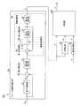
以下、本発明の実施形態について、図面を参照して詳細に説明する。図1は、第1の実施形態における表示装置10aの概略ブロック図である。表示装置10aは、受信部11と、シーンチェンジ検出部12aと、画像調整部13と、タイミング制御部14と、液晶表示部20と、映像記憶処理部21と、記憶部22と、入力部23と、映像切替部24とを備える。液晶表示部20は、ソースドライバ部15と、ゲートドライバ部16と、液晶パネル部17とを備える。<First Embodiment>
Hereinafter, embodiments of the present invention will be described in detail with reference to the drawings. FIG. 1 is a schematic block diagram of a
受信部11は、一例として、不図示のアンテナから供給されたデジタルテレビジョン放送の複数チャネルの高周波信号を受信する。受信部11は、受信した信号から希望のチャネルの高周波信号を抽出し、抽出した高周波信号をベースバンドの信号に変換し、変換したベースバンドの信号を所定のサンプリング周波数でデジタル信号へ変換する。
なお、受信部11は、不図示のアンテナから供給されたアナログテレビジョン放送の複数チャネルの高周波信号を受信して、これをデジタル信号へ変換する機能を有するものであってもよい。As an example, the receiving
The receiving
受信部11は、変換されたデジタル信号からデジタルデータMPEG(Moving Picture Experts Group)−2トランスポートストリーム(以下、「MPEG−2TS」と言う)信号を抽出する。 The receiving
受信部11は、MPEG−2TS信号からTS(Transport Stream、トランスポートストリーム)パケットを抽出し、映像信号および音声信号のデータを復号する。以下では、専ら映像信号の処理について説明をし、音声信号の処理については説明を省略する。
受信部11は、復号した映像信号をインターレース信号からプログレッシブ信号に変換する。そして、受信部11は、プログレッシブ信号に変換後の映像信号SINをシーンチェンジ検出部12aと映像記憶処理部21へ供給する。ここで、映像信号SINは、一例として、画像の主走査方向(横方向、水平方向)に隣接して並ぶ画素の輝度信号と、色差信号(Cb、Cr)と、水平同期信号HSYNCと、垂直同期信号VSYNCとからなるプログレッシブ信号である。The receiving
The receiving
シーンチェンジ検出部12aは、受信部11から供給された映像信号SINを受信する。シーンチェンジ検出部12aは、後述する処理によって受信した映像信号SINを構成する各フレームがシーンチェンジであるか否かを検出し、検出した結果を示すシーンチェンジ信号Vを映像記憶処理部21へ供給する。Scene
記憶部22は、ハードディスク記憶装置のような大容量記憶装置である。
映像記憶処理部21は、シーンチェンジ検出部12aから供給されたシーンチェンジ信号Vと受信部11から供給された映像信号SINとに基づいて、映像信号SINを構成する各フレームと、そのフレームがシーンチェンジしたか否かを示すシーンチェンジ情報とを関連付けて記憶部22に記憶させる。また、映像記憶処理部21は、シーンチェンジしたと判定したフレーム毎に、そのシーンを識別するシーン識別情報(例えば、映像中の何番目のシーンであるか示す情報)SIDを生成する。そして、映像記憶処理部21は、シーン識別情報SIDとそのフレームが映像中で何番目のフレームにあるかを示すフレーム順番情報とを関連づけて記憶させる。The
Image
入力部23は、不図示のリモートコントローラ(以下、リモコンと称す)から赤外線通信を介して、次のシーンへ切り替える旨を指示する次シーン切替信号Nの入力を受け付け、受け付けた次シーン切替信号Nを映像切替部24へ出力する。
また、入力部23は、不図示のリモコンから赤外線通信を介して、前のシーンへ切り替える旨を指示する前シーン切替信号Pの入力を受け付け、受け付けた前シーン切替信号Pを映像切替部24へ出力する。
また、入力部23は、不図示のリモコンから赤外線通信を介して、シーンの選択を受け付け、受け付けたシーンを識別するシーン識別情報SIDを映像切替部24へ出力する。The
Further, the
In addition, the
映像切替部24は、入力部23から入力された次シーン切替信号に基づいて、次のシーン以降の次シーン映像信号SNを記憶部22から読み出す。具体的には、例えば、映像切替部24は、現在表示しているフレーム以降のフレームであって、シーンチェンジを示すシーンチェンジ情報に対応するフレームのうち現在表示しているフレームに一番近いフレームから順次、フレームを記憶部22から読み出す。そして、映像切替部24は、順次読み出したフレームを次シーン映像信号SNとして画像調整部13へ供給する。The
映像切替部24は、入力部23から入力された前シーン切替信号に基づいて、前のシーン以降の前シーン映像信号SPを記憶部22から読み出す。具体的には、例えば、映像切替部24は、現在表示しているフレーム以前のフレームであって、シーンチェンジを示すシーンチェンジ情報に対応するフレームのうち現在表示しているフレームに一番近いフレームから順次、フレームを記憶部22から読み出す。そして、映像切替部24は、順次読み出したフレームを前シーン映像信号SPとして画像調整部13へ供給する。
映像切替部24は、入力部23から入力されたシーン識別情報SIDに対応するフレーム順番情報を参照し、参照したフレーム順番情報が示すフレーム順番のフレームから順次、映像信号を記憶部22から読み出す。そして、映像切替部24は、順次読み出した映像信号を画像調整部13へ供給する。 The
画像調整部13は、受信部11から供給された映像信号SINまたは映像切替部24から供給された信号の画素数を、表示部の解像度に合わせて調整するスケーリング処理を行う。画像調整部13は、スケーリング処理後の映像信号をRGB信号(Red、Green、Blueのカラービデオ信号)に変換する。画像調整部13は、RGB信号をタイミング制御部14と液晶表示部20内のソースドライバ部15とへ供給する。
なお、画像調整部13は、不図示のアンテナから供給されるテレビジョン放送信号がプログレッシブ信号であれば、前述のインターレース信号からプログレッシブ信号への変換をしない。その場合、画像調整部13は、映像信号SOUTの画素数を表示部の解像度に合わせて調整するスケーリング処理を行う。Note that if the television broadcast signal supplied from an antenna (not shown) is a progressive signal, the
タイミング制御部14は、液晶パネル部17に供給される映像データを平面上の画素に配分するためのクロック信号などを生成する。タイミング制御部14は、液晶表示部20内のソースドライバ部15と、ゲートドライバ部16へ、生成したクロック信号を供給する。 The
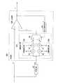
図2は、第1の実施形態における液晶表示部20の概略ブロック図である。液晶表示部20は、一例として、アクティブマトリクス型の表示装置である。液晶表示部20は、マトリクス状に配された画素PIXを有する液晶パネル部17と、ゲート線18と、ソース線19と、ゲート線18を駆動するゲートドライバ部16と、ソース線19を駆動するソースドライバ部15と、を備える。 FIG. 2 is a schematic block diagram of the liquid
ソースドライバ部15は、画像調整部13から供給されたRGB信号から液晶駆動用の階調化された電圧を生成する。ソースドライバ部15は、ソース線19ごとに、その階調化された電圧を、内部のホールド回路で保持する。
ソースドライバ部15は、タイミング制御部14から供給されたクロック信号を受信すると、画面の縦方向の配列に対して、クロック信号に同期して、階調化された電圧(ソース信号)を、液晶パネル部17のソース線19およびTFT(Thin Film Transistor、薄膜トランジスタ)を介して、各画素PIXの不図示のサブ画素に供給する。The
When the
ゲートドライバ部16は、タイミング制御部14から供給されたクロック信号を受信する。ゲートドライバ部16は、液晶パネル部17のTFTのゲート線18を通じて画面のサブ画素の1行分に対して、クロック信号に同期して、所定の走査信号を各TFTのゲートに供給する。 The
液晶パネル部17は、アレイ基板と対向基板と液晶とを備える。アレイ基板上のゲート線とデータ線との交点ごとに、TFTとTFTのドレイン電極に接続されている画素電極と対向電極(対向基板上のストリップ電極により構成されている)とが1組ずつ配置されて、画素、特にサブ画素を構成している。また、画素電極と対向電極との間には、封入された液晶が存在する。また、液晶パネル部17は、画素ごとに、3原色RGB(Red、Green、Blue)に対応する3つのサブ画素(不図示)を有する。液晶パネル部17は、そのサブ画素毎に1つずつのTFTを有する。これらのサブ画素はそれぞれのスイッチング素子であるTFT(薄膜トランジスタ)を介してゲート線18及びソース線19に接続される。 The liquid
TFTのゲート電極は、ゲートドライバ部16から供給されたゲート信号を受信して、ゲート信号が例えばハイレベルの時、そのTFTが選択されてオン状態となる。TFTのソース電極は、ソースドライバ部15から供給されたソース信号を受信するから、これによって、TFTのドレイン電極に接続されている画素電極に階調化された電圧が出現する。 The gate electrode of the TFT receives the gate signal supplied from the
その階調化された電圧に応じて、液晶の配向が変化し、これによって液晶の光の透過度が変化する。その階調化された電圧がTFTのドレイン電極に接続されている画素電極と対向電極との間の液晶部分により構成される液晶容量に保持されて、液晶の配向が維持される。また、次の信号がソース電極に到来するまで液晶の配向が維持され、その結果、液晶の光の透過度も維持される。 The alignment of the liquid crystal changes in accordance with the gradation voltage, thereby changing the light transmittance of the liquid crystal. The gradation voltage is held in the liquid crystal capacitor formed by the liquid crystal portion between the pixel electrode connected to the drain electrode of the TFT and the counter electrode, and the alignment of the liquid crystal is maintained. Further, the orientation of the liquid crystal is maintained until the next signal arrives at the source electrode, and as a result, the light transmittance of the liquid crystal is also maintained.
以上説明したようにして、液晶パネル部17は、供給された映像データを階調表示する。なお、本実施形態では透過型の液晶パネルについて説明したが、これに限定されず反射型の液晶パネルを用いてもよい。 As described above, the liquid
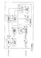
図3は、第1の実施形態におけるシーンチェンジ検出部12aの構成を示す概略ブロック図である。シーンチェンジ検出部12aは、フレーム間差分算出部30と、平滑化部40と、判定部50aとを備える。ここで、映像信号SINは、輝度信号および色差信号から成る。以後、輝度信号を例にシーンチェンジ検出部12aの処理を説明する。FIG. 3 is a schematic block diagram showing the configuration of the scene
フレーム間差分算出部30は、受信部11から入力された映像信号SINを構成する各フレームに対して、シーンチェンジしたか否かの判定の対象となる対象フレームと該対象フレームの直前のフレーム(以下、直前フレームとも称する)との間で、対象フレームの画素値と該対象フレームの画素値の位置に相当する直前フレームの画素値との差分を算出する。そして、フレーム間差分算出部30は、算出した差分の絶対値の総和をフレーム間差分値Dとして算出し、算出したフレーム間差分値Dを対象フレームの次のフレームの画像信号が入力される期間に、平滑化部40と判定部50aとへ出力する。Interframe
すなわち、フレーム間差分算出部30は、画像信号に基づいて、フレーム間の画素値の差分であるフレーム間差分値Dを算出する。
ここで、フレーム間差分算出部30は、第1の遅延部31(遅延部)と、差分算出部32と、絶対値算出部33と、累積加算部34とを備える。That is, the inter-frame
Here, the inter-frame
第1の遅延部31は、受信部11から入力された映像信号SINを構成する画像信号を1フレーム分遅延させる。ここで、画像信号は、ラスタースキャンされているものとする。そして、第1の遅延部31は、1フレーム分遅延させた遅延信号SDを差分算出部32へ供給する。ここで、遅延信号SDは、シーンチェンジしたか否かを検出する対象となる対象フレームの画素値の位置に相当する位置における直前フレームの画素値を示す信号である。The
差分算出部32は、第1の遅延部31から入力された遅延信号SDから、受信部11から入力された対象フレームの画素値を示す信号を減算し、減算により得られたフレーム間の画素値の差分を示す信号を絶対値算出部33へ供給する。
絶対値算出部33は、差分算出部32から供給されたフレーム間の画素値の差分を示す信号が示す差分の絶対値を算出し、算出した絶対値を示す絶対値信号を累積加算部34へ供給する。The difference calculation unit 32 subtracts a signal indicating the pixel value of the target frame input from the
The absolute
累積加算部34は、絶対値算出部33から供給された絶対値信号が示す絶対値を1フレーム分加算し、1フレーム分加算することにより得られるフレーム間差分値Dを生成する。すなわち、累積加算部34は、各画素における差分の絶対値を1フレーム内の有効画素にわたって加算を行い、フレーム毎に、フレーム間差分値Dを算出する。そして、累積加算部34は、算出したフレーム間差分値Dを示す信号を平滑化部40と判定部50aへ供給する。また、累積加算部34は0を示す信号を保持している。 The
ここで、累積加算部34は、第1の加算部35と、第1の選択部36と、第2の遅延部37と、第1の保持部38と、垂直同期信号抽出部39とを備える。
第1の加算部35は、絶対値算出部33から供給された絶対値信号と第2の遅延部37から入力された累積加算値Aを示す信号とを加算し、加算後の信号を第1の選択部36へ供給する。
垂直同期信号抽出部39は、受信部11から供給された映像信号SINから垂直同期信号VSYNCを抽出し、抽出した垂直同期信号VSYNCを第1の選択部36と第1の第1の保持部38とへ供給する。Here, the
The
Vertical synchronizing
第1の選択部36は、垂直同期信号抽出部39から供給された垂直同期信号VSYNCが0の間は、第1の加算部35から供給された加算後の信号を第2の遅延部37へ供給する。ここで、垂直同期信号VSYNCは、垂直帰線区間で1であり、それ以外で0である。すなわち、1フレーム中の画像信号が入力されている間、第1の選択部36は、第1の加算部35から供給された加算後の信号を第2の遅延部37へ供給する。
一方、垂直帰線区間において、第1の選択部36に、値が1である垂直同期信号VSYNCが供給された場合、累積加算部34が保持する0を示す信号を第2の遅延部37へ出力する。これにより、第2の遅延部37の出力値である累積加算値Aがリセットされる。While the vertical synchronization signal VSYNC supplied from the vertical synchronization
On the other hand, when a vertical synchronization signal VSYNC having a value of 1 is supplied to the first selector 36 in the vertical blanking interval, a signal indicating 0 held by the
第2の遅延部37は、第1の選択部36から供給された信号を、1ピクセルクロックだけ遅延させる。そして、第2の遅延部37は、1ピクセルクロックだけ遅延させた信号を、累積加算値Aを示す信号として、第1の加算部35と第1の保持部38とへ供給する。
これにより、第1の加算部35は、帰線区間でない場合は、絶対値算出部33から入力された差分の絶対値と第2の遅延部37から入力された1ピクセル前までの累積加算値Aとを加算することによって、累積加算を行う。
一方、第1の加算部35は、垂直帰線区間において、絶対値算出部33から入力された差分の絶対値と0とを加算するので、累積加算値Aがリセットされる。The
Thereby, when it is not a blanking interval, the
On the other hand, since the
第1の保持部38は、垂直同期信号抽出部39から供給された垂直同期信号VSYNCが0から1になる立ち上がりを検出すると、保持していた累積加算値Aをフレーム間差分値Dと、フレーム間差分値Dを示す信号を平滑化部40と判定部50aとへ出力する。第1の保持部38は、次の垂直同期信号VSYNCが0から1になる立ち上がりが検出されるまで、同一のフレーム間差分値Dを示す信号を平滑化部40と判定部50aとへ出力する。第1の保持部38は、例えば、Dフリップフロップである。 When the
平滑化部40は、累積加算部34から供給されたフレーム間差分値Dを複数のフレーム区間にわたり平滑化する。具体的には、例えば、平滑化部40は、直前のフレームであって、予め決められたフレーム数(例えば、直前の8フレーム)分のフレーム間差分値Dの平均値を算出する。平滑化部40は、平滑化により得られた比較値Daを示す比較値信号を判定部50aへ出力する。 The smoothing
なお、本実施形態では、比較値Daをフレーム間差分値Dの平均値としてが、これに限らず、フレーム間差分値の中央値でもよい。また、平滑化部40は、予め決められたフレーム数分のフレーム間差分値Dに対して、ローパスフィルタをかけることにより、比較値Daを算出してもよい。 In the present embodiment, the comparison value Da is the average value of the inter-frame difference values D, but is not limited to this, and may be the median of the inter-frame difference values. Further, the smoothing
また、本実施形態では、平滑化部40は、比較値として、直近のフレームであって、予め決められたフレーム数(例えば、8フレーム)のフレームを用いて算出したが、これに限らず、平滑化部40は、対象フレーム以外のフレーム間差分値Dに基づいて、対象フレームのフレーム間差分値Dを平滑化すればよい。 In the present embodiment, the smoothing
すなわち、比較値は、対象フレーム以外のフレームにおけるフレーム間差分値Dに基づく値であればよい。例えば、比較値は、対象フレームの近傍のフレームにおけるフレーム間差分値Dに基づく値でもよい。また、比較値は、対象フレームと隣接しているフレームのフレーム間差分値Dに基づく値でもよい。また、比較値は、対象フレームの後のフレームのフレーム間差分値Dに基づく値でもよい。また、比較値は、対象フレームの前と後のフレームのフレーム間差分値Dに基づく値でもよい。 That is, the comparison value may be a value based on the inter-frame difference value D in a frame other than the target frame. For example, the comparison value may be a value based on the inter-frame difference value D in a frame near the target frame. Further, the comparison value may be a value based on the inter-frame difference value D between frames adjacent to the target frame. Further, the comparison value may be a value based on the inter-frame difference value D of the frame after the target frame. Further, the comparison value may be a value based on the inter-frame difference value D between the frame before and after the target frame.
判定部50aは、フレーム間差分算出部30の累積加算部34から供給されたフレーム間差分値Dを示す信号と、平滑化部40から供給された比較値Daを示す信号とに基づいて、対象フレームがシーンチェンジしたか否か判定する。そして、判定部50aは、判定した結果を示すシーンチェンジ信号Vを映像記憶処理部21に供給する。 The determination unit 50a is based on the signal indicating the inter-frame difference value D supplied from the
図4は、フレーム間差分値Dの算出処理を説明するための図である。同図において、上から1段目に原画像である第1の遅延部31へ入力される映像信号SINが示す画像X41〜X46が、時間tの経過とともに示されている。また、同図の上から2段目に、1段目の画像を示す画像信号が第1の遅延部31に入力された場合に、第1の遅延部31から出力される遅延信号SDが示す画像Y41〜Y46が、時間tの経過とともに示されている。ここで、同図の上から2段目の画像は、1段目の画像よりも1フレーム遅れていることが示されている。FIG. 4 is a diagram for explaining the calculation process of the inter-frame difference value D. In the figure, the image X41~X46 indicated by a picture signal SIN input to the
また、同図の上から1段目の画像を示す画像信号が第1の遅延部31に入力され、かつ同図の上から2番目の画像を示す遅延信号SDが第1の遅延部31から出力される場合において、同図の上から3段目には累積加算部34内の累積加算値Aの時間変化が示されている。ここで、累積加算値Aは、時間の経過とともに単調に増加し、1フレーム分の画像信号の第1の遅延部31への入力が終わると、0にリセットされている。In addition, an image signal indicating the first-stage image from the top of the figure is input to the
また、同図の上から3段目のように累積加算値Aが時間変化する場合に、同図の上から4段目にフレーム間差分値Dの時間変化が示されている。ここで、フレーム間差分値Dは、各フレーム内で同一の値を示し、その値は、対象フレーム開始の直前の時刻における画像累積加算値Aである。例えば、時刻t3からt4までのフレーム間差分値Dは、時刻t3の直前の累積加算値Aである。 Further, when the cumulative addition value A changes with time as shown in the third row from the top of the figure, the time change of the interframe difference value D is shown at the fourth row from the top of the figure. Here, the inter-frame difference value D indicates the same value in each frame, and the value is the image cumulative addition value A at the time immediately before the start of the target frame. For example, the inter-frame difference value D from time t3 to t4 is the cumulative addition value A immediately before time t3.
図5は、第1の実施形態における判定部50aの概略ブロック図である。判定部50aは、閾値算出部51と、比較部59とを備える。
閾値算出部51は、平滑化部40から供給された比較値信号が示す比較値Daに基づいて、閾値Tを算出し、算出した閾値Tを示す閾値信号を比較部59へ供給する。FIG. 5 is a schematic block diagram of the determination unit 50a in the first embodiment. The determination unit 50 a includes a threshold
The
ここで、閾値算出部51は、第1の乗算部53と第2の加算部54とを備える。第1の乗算部53は、平滑化部40から供給された比較値信号が示す比較値Daに、予め決められた傾きaLを乗じ、乗算後の値を示す信号を第2の加算部54へ供給する。
第2の加算部54は、第1の乗算部53から供給された乗算後の値を示す信号に切片bLを加算し、加算により得られた信号を閾値を示す閾値信号として比較部59へ供給する。Here, the threshold
The
比較部59は、フレーム間差分算出部30の累積加算部34から供給されたフレーム間差分値Dを示す信号と、閾値算出部51の第2の加算部54から供給された閾値信号とを比較する。比較部59は、フレーム間差分値Dが閾値信号が示す閾値より大きい場合、シーンチェンジ信号Vの値を1とし、そのシーンチェンジ信号Vを映像記憶処理部21へ供給する。すなわち、比較部59は、フレーム間差分値Dが閾値信号が示す閾値より大きい場合、対象フレームがシーンチェンジしたと判定する。 The comparison unit 59 compares the signal indicating the inter-frame difference value D supplied from the
一方、比較部59は、フレーム間差分値Dが閾値信号が示す閾値以下の場合、シーンチェンジ信号Vの値を0とし、そのシーンチェンジ信号Vを映像記憶処理部21へ供給する。すなわち、比較部59は、フレーム間差分値Dが閾値信号が示す閾値以下の場合、対象フレームがシーンチェンジしていないと判定する。
以上により、比較部59は、フレーム間差分算出部30が算出したフレーム間差分値Dと閾値算出部51が算出した閾値との比較に基づいて、対象フレームがシーンチェンジしたか否か判定する。On the other hand, when the interframe difference value D is equal to or less than the threshold value indicated by the threshold signal, the comparison unit 59 sets the value of the scene change signal V to 0 and supplies the scene change signal V to the video
As described above, the comparison unit 59 determines whether the target frame has undergone a scene change based on the comparison between the inter-frame difference value D calculated by the inter-frame
続いて、図6〜8を用いて、第1の実施形態における判定部50aの処理を説明する。図6は、フレーム間差分値Dと比較値Daとの関係の一例が示された図である。同図において、従来の閾値を示す直線L61と、本実施形態の閾値Tを示す直線L62とが示されている。ここで、直線L62は、傾きaおよび切片bであり、T=a×Da+bで表される。 Then, the process of the determination part 50a in 1st Embodiment is demonstrated using FIGS. FIG. 6 is a diagram showing an example of the relationship between the inter-frame difference value D and the comparison value Da. In the figure, a straight line L61 indicating the conventional threshold value and a straight line L62 indicating the threshold value T of the present embodiment are shown. Here, the straight line L62 has an inclination a and an intercept b, and is represented by T = a × Da + b.
従来の閾値を示す直線L61が示すように、従来の閾値は、比較値Daによらず一定である。そのため、比較値Daが小さい場合に、シーンチェンジしたときのフレーム間差分値Dが従来の閾値以下になる場合(例えば、点P63、点P64)があり、この場合、従来の装置は、実際にはシーンチェンジしているにも関わらずシーンチェンジを検出できない。また、比較値Daが中程度の場合に、シーンチェンジしていないときのフレーム間差分値Dが従来の閾値を超えている場合(例えば、点P65〜点P67)があり、この場合、従来の装置は、実際にはシーンチェンジしていないにも関わらずシーンチェンジしたと誤検出してしまう。 As indicated by the straight line L61 indicating the conventional threshold value, the conventional threshold value is constant regardless of the comparison value Da. Therefore, when the comparison value Da is small, there are cases where the inter-frame difference value D when the scene is changed is less than or equal to the conventional threshold (for example, point P63, point P64). In this case, the conventional apparatus actually Cannot detect a scene change despite the scene change. Further, when the comparison value Da is medium, there is a case where the inter-frame difference value D when the scene is not changed exceeds a conventional threshold value (for example, point P65 to point P67). The device erroneously detects that the scene has changed even though the scene has not actually changed.
一方、本実施形態の閾値Tを示す直線L62が示すように、閾値Tは、比較値Daが大きくなるほど、線形に大きくなっている。同図において、シーンチェンジしたときのフレーム間差分値Dが閾値Tを超えていることが示されている。また、シーンチェンジしていないときのフレーム間差分値Dが閾値T以下であることが示されている。
このように、本実施形態の閾値算出部51は、比較値Daに応じて閾値Tを変動させることにより、判定部50aは、対象フレームがシーンチェンジしたか否かを従来よりも高い精度で判定することができる。On the other hand, as indicated by the straight line L62 indicating the threshold value T in the present embodiment, the threshold value T increases linearly as the comparison value Da increases. In the figure, it is shown that the inter-frame difference value D when the scene is changed exceeds the threshold value T. Further, it is shown that the inter-frame difference value D when the scene is not changed is equal to or less than the threshold value T.
Thus, the threshold
なお、本実施形態では、閾値算出部51は、閾値Tを比較値Daに応じて線形に増加させたが、これに限らず、非線形に増加させてもよい。 In the present embodiment, the threshold
図7は、従来の閾値を用いた判定について説明する際の問題点について説明するための図である。同図において、フレーム間差分値Dのフレーム変化を示す曲線L71と、従来の閾値を示す直線L72とが示されている。また、星型のマークは、実際にシーンチェンジしたときのフレーム間差分値Dを示している。
領域R73のフレームでは、実際にはパンであるにも関わらず、フレーム間差分値Dが閾値を超えているため、シーンチェンジしたと判定されてしまう。
点P74のフレーム及び点P75のフレームでは、実際にはシーンチェンジしているにも関わらず、フレーム間差分値Dが閾値以下のために、シーンチェンジしていないと判定されてしまう。FIG. 7 is a diagram for explaining a problem in explaining determination using a conventional threshold value. In the figure, a curve L71 indicating a frame change of the inter-frame difference value D and a straight line L72 indicating a conventional threshold are shown. The star-shaped mark indicates the inter-frame difference value D when the scene is actually changed.
In the frame of the region R73, although the pan is actually pan, the inter-frame difference value D exceeds the threshold value, so that it is determined that the scene has been changed.
In the frame at the point P74 and the frame at the point P75, although the scene change is actually performed, it is determined that the scene change has not occurred because the inter-frame difference value D is equal to or less than the threshold value.
図8は、本実施形態の閾値Tを用いた判定について説明するための図である。同図において、フレーム間差分値Dのフレーム毎の変化を示す曲線L81と、閾値Tを示す曲線L82とが示されている。また、星型のマークは、実際のシーンチェンジしたときのフレーム間差分値Dを示している。
同図において、シーンチェンジしたときのフレーム間差分値Dの全てが、閾値Tを越えていることが示されている。FIG. 8 is a diagram for explaining determination using the threshold value T of the present embodiment. In the figure, a curve L81 indicating a change of the interframe difference value D for each frame and a curve L82 indicating a threshold T are shown. A star-shaped mark indicates an inter-frame difference value D when an actual scene change is made.
In the figure, it is shown that all of the inter-frame difference values D when the scene changes exceeds the threshold T.
また、実際にパンをしているフレームである領域R83のフレームでは、フレーム間差分値Dが閾値T以下のため、判定部50aはシーンチェンジしていないと判定することができる。
実際にフレームチェンジしている点P84のフレーム及び点P85のフレームでは、フレーム間差分値Dが閾値Tを越えているため、判定部50aはシーンチェンジしたと判定することができる。Further, since the interframe difference value D is equal to or less than the threshold value T in the frame of the region R83 that is actually a panning frame, the determination unit 50a can determine that no scene change has occurred.
Since the inter-frame difference value D exceeds the threshold value T at the point P84 frame and the point P85 frame that have actually undergone frame change, the determination unit 50a can determine that a scene change has occurred.
このように、従来では、フレーム間差分値Dの値に関わらず固定の閾値を用いていたため、フレーム間差分値Dが小さい場合のパンとシーンチェンジとを分別することができなかったが、本実施形態の判定部50aは、フレーム間差分値Dの値に応じて閾値を変動させつことで、フレーム間差分値Dが小さい場合のパンとシーンチェンジとを分別することができる。よって、判定部50aは、対象フレームがシーンチェンジしたか否かを従来よりも高い精度で判定することができる。 As described above, conventionally, a fixed threshold value is used regardless of the value of the inter-frame difference value D. Therefore, panning and scene change when the inter-frame difference value D is small cannot be distinguished. The determination unit 50a of the embodiment can discriminate panning and scene change when the inter-frame difference value D is small by changing the threshold value according to the inter-frame difference value D. Therefore, the determination unit 50a can determine whether or not the target frame has undergone a scene change with higher accuracy than before.
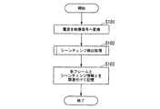
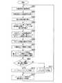
図9は、第1の実施形態における表示装置10aの映像の保存処理の流れの一例を示すフローチャートである。まず、受信部11は、アンテナから電波を受信する。受信部11は、受信した電波を映像信号に変換する(ステップS101)。受信部11は、変換した映像信号をシーンチェンジ検出部12aと映像記憶処理部21へ供給する。シーンチェンジ検出部12aは、受信部11から供給された映像信号に基づいて、対象フレームがシーンチェンジしたか否か判定する(ステップS102)。シーンチェンジ検出部12aは、判定した結果を示すシーンチェンジ信号Vを映像記憶処理部21へ供給する。 FIG. 9 is a flowchart illustrating an example of a flow of video storage processing of the
映像記憶処理部21は、シーンチェンジ検出部12aから供給されたシーンチェンジ信号Vと受信部11から供給された映像信号SINとに基づいて、映像信号SINを構成する各フレームと、そのフレームがシーンチェンジしたか否かを示すシーンチェンジ情報とを関連付けて記憶部22に記憶させる(ステップS103)。以上で、本フローチャートの処理を終了する。Image
これにより、表示装置10aは、受信した映像信号をフレーム毎に、判定の対象となる対象フレームがシーンチェンジであるか否か判定し、その判定結果を示すシーンチェンジ情報と当該対象フレームの画像とを関連づけて記憶する。これにより、表示装置10aは、記憶されたシーンチェンジ情報を参照することにより、シーン毎に映像信号を再生することができる。また、本実施形態の表示装置10aは、映像を再生中に、次のシーンへスキップする場合、現在再生中のシーンの次のシーンのシーンチェンジ情報に関連づけられた映像を読み出して表示することにより、シーン毎に映像をスキップすることができる。同様に、表示装置10aは、映像を再生中に、前のシーンへスキップする場合、現在再生中のシーンの前のシーンのシーンチェンジ情報に関連づけられた映像を読み出して表示することにより、シーン毎に映像を巻き戻すことができる。 Thereby, the
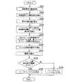
図10は、図9のステップS102におけるシーンチェンジ検出処理の流れの一例を示すフローチャートである。まず、第1の遅延部31は、映像信号SINを遅延させ、遅延信号SDを生成する(ステップS201)。次に,差分算出部32は、映像信号SINから遅延信号を差分する(ステップS202)。次に、絶対値算出部33は、差分の絶対値を算出する(ステップS203)。次に、累積加算部34は、1フレームに渡って差分の絶対値を加算することにより、フレーム間差分値Dを算出する(ステップS204)。次に、累積加算部34は、対象フレームの次のフレームの映像信号が入力されている間、対象フレームのフレーム間差分値Dを示す信号を出力する(ステップS205)FIG. 10 is a flowchart showing an example of the flow of the scene change detection process in step S102 of FIG. First, the
次に、平滑化部40は、一例として直近の近傍数フレームに渡って、フレーム間差分値Dを平滑化することにより比較値Daを算出する(ステップS206)。次に、判定部50aは、比較値Daに基づいて、閾値Tを算出する(ステップS207)。次に、判定部50aは、フレーム間差分値Dが閾値T以上か否か判定する(ステップS208)。フレーム間差分値Dが閾値T以上である場合(ステップS208 YES)、判定部50aは、シーンチェンジと判定し(ステップS209)、値が1を示すシーンチェンジ信号Vを映像記憶処理部21へ供給する。フレーム間差分値Dが閾値T未満である場合(ステップS208 NO)、判定部50aは、シーンチェンジでないと判定し(ステップS210)、値が0を示すシーンチェンジ信号Vを映像記憶処理部21へ供給する。以上で、本フローチャートの処理を終了する。 Next, for example, the smoothing
これにより、シーンチェンジ検出部12aは、一例として直近の近傍数フレームに渡ってフレーム間差分値Dを平滑化することにより比較値Daを算出し、その比較値Daに基づいて閾値Tを算出する。これにより、閾値Tは、対象フレームの直近の近傍数フレームに基づいて変動する。これにより、フレーム間差分値Dが時間の経過とともに急峻に上昇するシーンチェンジ時には、シーンチェンジのフレームのフレーム間差分値Dに対して直近の近傍数フレームのフレーム間差分値Dの平均である比較値Daが、充分に小さいので、判定部50aは、閾値Tをシーンチェンジ時のフレーム間差分値Dより小さい値として算出する。これにより、シーンチェンジ時のフレーム間差分値Dを閾値T以上になるので、判定部50aは、シーンチェンジを高精度で検出することができる。 Thereby, the scene
一方、フレーム間差分値Dが時間の経過とともになだらかに上昇するパンのときには、直近の近傍数フレームのフレーム間差分値Dの平均である比較値Daが、シーンチェンジフレームの直近の近傍数フレームのフレーム間差分値Dの平均である比較値Daより大きくなる傾向にあるので、判定部50aは、パンの際の閾値Tをその際のフレーム間差分値Dより大きい値として算出する。これにより、パン時のフレーム間差分値Dが閾値T未満になるので、判定部50aは、パンをシーンチェンジと誤検出することを防ぐことができ、シーンチェンジを高精度で検出することができる。 On the other hand, in the case of pan in which the inter-frame difference value D rises gradually with time, the comparison value Da, which is the average of the inter-frame difference values D of the nearest neighbor frames, is the value of the nearest neighbor frames of the scene change frame. Since it tends to be larger than the comparison value Da that is the average of the inter-frame difference values D, the determination unit 50a calculates the threshold value T for panning as a value larger than the inter-frame difference value D at that time. As a result, since the inter-frame difference value D during panning is less than the threshold value T, the determination unit 50a can prevent erroneous detection of pan as a scene change, and can detect a scene change with high accuracy. .
図11は、第1の実施形態における表示装置10aの再生処理の流れの一例を示すフローチャートである。まず、映像切替部24は、映像信号を記憶部22から読み出し、読み出した映像信号を画像調整部13へ供給する(ステップS301)。次に、画像調整部13は、映像切替部24から供給されたノイズを低減した輝度信号を受信する。画像調整部13は、そのノイズを低減した輝度信号をI/P変換する(インターレース信号からプログレッシブ信号への変換を行う)(ステップS302)。画像調整部13は、I/P変換された信号の画素数を調整する。画像調整部13は、画素数調整後の調整後信号をタイミング制御部14と、ソースドライバ部15とへ供給する。 FIG. 11 is a flowchart illustrating an example of the flow of the reproduction process of the
次に、タイミング制御部14は、画像調整部13から供給された調整後信号を受信する。タイミング制御部14は、その調整後信号を平面上の画素に配分するためのクロック信号を生成する(ステップS303)。タイミング制御部14は、ソースドライバ部15と、ゲートドライバ部16へ、生成したクロック信号を供給する。 Next, the
次に、ソースドライバ部15は、その調整後信号から液晶駆動用の階調化された電圧を生成する(ステップS304)。ソースドライバ部15は、ソース線ごとに、その階調化された電圧を、内部のホールド回路で保持する。
次に、ゲートドライバ部16は、所定の電圧を液晶パネル部17のTFTのゲート線に供給する(ステップS305)。
次に、ソースドライバ部15は、画面の縦方向の配列に対して、クロック信号に同期して、階調化された電圧を液晶パネル部17のTFTのソース線に供給する(ステップS306)。Next, the
Next, the
Next, the
これにより、各ゲート線が選択されている時間内に映像データが、ソース線に順次供給され、必要なデータがTFTを介して画素電極に書き込まれる。これによって、画素電極は、画素電極に掛かる電圧に応じて、対応する液晶の透過率を変更する。これによって、液晶パネル部17は、映像信号を表示する(ステップS307)。 As a result, video data is sequentially supplied to the source line within a time when each gate line is selected, and necessary data is written to the pixel electrode via the TFT. Thereby, the pixel electrode changes the transmittance of the corresponding liquid crystal according to the voltage applied to the pixel electrode. Thereby, the liquid
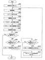
次に、映像切替部24は、映像信号を全て読み出したか否か判定する(ステップS308)。映像切替部24は、映像信号を全て読み出していないと判定した場合(ステップS308 NO)、入力部23から次シーン切替信号Nが入力されたか否か判定する(ステップS309)。映像切替部24は、次シーン切替信号Nが入力されたと判定した場合(ステップS309 YES)、次シーン映像信号SNを記憶部22から読み出し(ステップS310)、読み出した次シーン映像信号SNを画像調整部13へ供給し、ステップS302の処理に戻る。Next, the
一方、映像切替部24は、次シーン切替信号Nが入力されていないと判定した場合(ステップS309 NO)、入力部23から前シーン切替信号Pが入力されたか否か判定する(ステップS311)。映像切替部24は、前シーン切替信号Pが入力されたと判定した場合(ステップS311 YES)、映像切替部24は、前シーン映像信号SPを記憶部22から読み出し(ステップS312)、読み出した前シーン映像信号SPを画像調整部13へ供給し、ステップS302の処理に戻る。On the other hand, when it is determined that the next scene switching signal N is not input (NO in step S309), the
映像切替部24は、前シーン切替信号Pが入力されていないと判定した場合(ステップS311 NO)、次のフレームの映像信号を記憶部22から読み出し(ステップS313)、読み出した次のフレームの映像信号を画像調整部13へ供給し、ステップS302の処理に戻る。ステップS308において、映像切替部24は、映像信号を全て読み出したと判定した場合(ステップS308 YES)、表示装置10aは、本フローチャートの処理を終了する。 When the
以上、本実施形態の表示装置10aは、映像を再生中に、現在再生中のシーンの次のシーンへのシーンチェンジを示すシーンチェンジ情報に関連づけられた映像を読み出して表示することにより、シーン毎に映像をスキップすることができる。同様に、表示装置10aは、現在再生中のシーンの前のシーンへのシーンチェンジを示すシーンチェンジ情報に関連づけられた映像を読み出して表示することにより、シーン毎に映像を巻き戻すことができる。 As described above, the
<第2の実施形態>
次に、本発明の第2の実施形態について説明する。図12は、第2の実施形態における表示装置10bの概略ブロック図である。なお、図1と共通する要素には同一の符号を付し、その具体的な説明を省略する。
図12の表示装置10bの構成は、図1の表示装置10aの構成に対して、シーンチェンジ検出部12aが、シーンチェンジ検出部12bに変更されたものとなっている。<Second Embodiment>
Next, a second embodiment of the present invention will be described. FIG. 12 is a schematic block diagram of a
The configuration of the
図13は、第2の実施形態におけるシーンチェンジ検出部12bの概略ブロック図である。なお、図3と共通する要素には同一の符号を付し、その具体的な説明を省略する。
図13のシーンチェンジ検出部12bの構成は、図3のシーンチェンジ検出部12aの構成に対して、判定部50aが判定部50bに変更されたものになっている。FIG. 13 is a schematic block diagram of the scene
The configuration of the scene
図14は、第2の実施形態における判定部50bの概略ブロック図である。なお、図5と共通する要素には同一の符号を付し、その具体的な説明を省略する。図13の判定部50bの構成は、図5の判定部50aの構成に対して、閾値算出部51が閾値算出部51bに変更され、比較部59が比較部59bに変更され、第2の保持部60が追加されたものになっている。 FIG. 14 is a schematic block diagram of the
閾値算出部51bは、平滑化部40から供給された比較値Daを示す信号に基づいて、閾値Tを算出し、算出した閾値Tを示す信号を比較部59bに供給する。
ここで、閾値算出部51は、下閾値算出部52bと、上閾値算出部55bと、第2の選択部(選択部)58とを備える。The
Here, the threshold
下閾値算出部52bは、平滑化部40から供給された比較値Daを示す信号が示す比較値Daに基づいて下閾値TLを算出し、算出した下閾値TLを示す信号を第2の選択部58へ供給する。
ここで、下閾値算出部52bは、第1の乗算部53と、第2の加算部54とを備える。第1の乗算部53は、平滑化部40から供給された比較値Daを示す信号に予め決められた傾きaLを示す信号を乗じ、乗じた後の信号を第2の加算部54へ供給する。
第2の加算部54は、第1の乗算部53から供給された乗じた後の信号に、予め決められた切片bLを示す信号を加算し、加算後の信号を、下閾値TLを示す信号として第2の選択部58へ供給する。ここで、下閾値TLは、aL×Da+bLで表される。The lower threshold value calculation unit 52b calculates a lower threshold valueTL based on the comparison value Da indicated by the signal indicating the comparison value Da supplied from the smoothing
Here, the lower threshold value calculation unit 52 b includes a
The
上閾値算出部55bは、比較値Daに基づいて、該比較値Daに基づいて下閾値算出部52bが算出する下閾値TLより大きい上閾値THを算出し、算出した上閾値THを示す信号を第2の選択部58供給する。
ここで、上閾値算出部55bは、第2の乗算部56と、第3の加算部57とを備える。第2の乗算部56は、平滑化部40から供給された比較値Daを示す信号に予め決められた傾きaH(但し、aHはaL以上)を示す信号を乗じ、乗じた後の信号を第3の加算部57へ供給する。
第3の加算部57は、第2の乗算部56から供給された乗じた後の信号に、予め決められた切片bH(但し、bHはbL以上)を示す信号を加算し、加算後の信号を、上閾値THを示す信号として第2の選択部58へ供給する。ここで、上閾値THは、aH×Da+bHで表される。Upper threshold value calculation unit 55b, based on the comparison value Da, calculates the lower threshold TL greater than the threshold TH of calculating the lower threshold value calculation unit 52b based on the comparison value Da, the threshold TH on calculated The signal shown is supplied to the
Here, the upper threshold value calculation unit 55 b includes a
The
第2の選択部58は、比較部59bが直前のフレームに対してシーンチェンジしたか否か判定した判定結果に基づいて、下閾値TLと上閾値THのいずれか一方を閾値Tとして選択する。具体的には、第2の選択部58は、第2の保持部60から比較部59bが直前のフレームに対してシーンチェンジしたか否か判定した判定結果を示す信号を受け取る。そして、第2の保持部60から受け取った信号がシーンチェンジをした旨を示す場合(例えば、信号が1を示す場合)、第2の選択部58は、上閾値THを閾値Tに選択する。一方、第2の保持部60から受け取った信号がシーンチェンジをしていない旨を示す場合(例えば、信号が0を示す場合)、第2の選択部58は、下閾値TLを閾値Tに選択する。
すなわち、第2の選択部58は、比較部59bが対象フレームの直前のフレームについてシーンチェンジしたと判定した場合、上閾値THを閾値Tに選択する。第2の選択部58は、比較部59bが対象フレームの直前のフレームについてシーンチェンジしていないと判定した場合、下閾値TLを閾値Tとして選択する。
そして、第2の選択部58は、選択した閾値Tを示す信号を比較部59bに供給する。That is, the
Then, the
これにより、第2の選択部58は、シーンチェンジしたか否か判定する対象となる対象フレームの直前のフレームにおいて、シーンチェンジしたと判定した場合に、閾値Tを上昇させる。これにより、シーンチェンジの直後にパンが始まる場合、判定部50bは、シーンチェンジ直後の閾値Tを上昇させることにより、当該パンをシーンチェンジと誤検出することを防ぐことができるので、シーンチェンジを高精度で検出することができる。 As a result, the
比較部59bは、累積加算部34から供給されたフレーム間差分値Dを示す信号と、閾値算出部51bから供給された閾値Tとに基づいて、当該フレーム間差分値Dに対応する対象フレームがシーンチェンジしたか否か判定する。
具体的には、例えば、比較部59bは、フレーム間差分値Dが閾値T以上の場合、シーンチェンジ信号Vの値を1とする。ここで、シーンチェンジ信号Vの値が1の場合、対象フレームがシーンチェンジしたことを示すことから、上記処理により比較部59bは、フレーム間差分値Dが閾値T以上の場合、対象フレームがシーンチェンジしたと判定する。Based on the signal indicating the inter-frame difference value D supplied from the
Specifically, for example, the comparison unit 59b sets the value of the scene change signal V to 1 when the inter-frame difference value D is equal to or greater than the threshold value T. Here, when the value of the scene change signal V is 1, it indicates that the target frame has changed, so that the comparison unit 59b performs the above processing when the inter-frame difference value D is equal to or greater than the threshold value T. Judge that it has changed.
一方、比較部59bは、フレーム間差分値Dが閾値T未満の場合、シーンチェンジ信号Vの値を0とする。ここで、シーンチェンジ信号Vの値が0の場合、対象フレームがシーンチェンジしていないことを示すことから、上記処理により比較部59bは、フレーム間差分値Dが閾値T未満の場合、対象フレームがシーンチェンジしていないと判定する。 On the other hand, the comparison unit 59b sets the value of the scene change signal V to 0 when the inter-frame difference value D is less than the threshold value T. Here, when the value of the scene change signal V is 0, it indicates that the target frame has not changed, so that the comparison unit 59b performs the above processing when the inter-frame difference value D is less than the threshold T. Determines that the scene has not changed.
比較部59bは、シーンチェンジ信号Vを第2の保持部60と映像記憶処理部21とへ供給する。
第2の保持部60は、不図示のクロック信号の立ち上がりに比較部59bから供給されたシーンチェンジ信号Vを取り込み、取り込んだシーンチェンジ信号Vを第2の選択部58へ供給する。そして、第2の保持部60は、次のクロック信号の立ち上がりまで、その取り込んだシーンチェンジ信号Vを第2の選択部58へ供給する。第2の保持部60は、例えば、Dフリップフロップである。The comparison unit 59b supplies the scene change signal V to the
The
これにより、第2の保持部60は、対象フレームについてのシーンチェンジ信号Vを、対象フレームの次のフレームの閾値Tを算出する処理のときに、第2の選択部58へ供給する。その結果、第2の選択部58は、対象フレームのシーンチェンジ信号Vが1の場合、すなわち対象フレームがシーンチェンジした場合、対象フレームの次のフレームのときに、閾値Tとして上閾値THを選択することができる。また、第2の選択部58は、対象フレームのシーンチェンジ信号Vが0の場合、すなわち対象フレームがシーンチェンジしていない場合、対象フレームの次のフレームのときに、閾値Tとして下閾値TLを選択することができる。As a result, the
続いて、図15を用いて、上閾値TH及び下閾値TLとの関係を説明する。図15は、上閾値TH及び下閾値TLと比較値Daとの関係を示した図である。同図において、下閾値TLを示す直線L151と、上閾値THを示す直線L152とが示されている。同図において、比較値Daが0以上の値において、同一の比較値Daに対して常に、上閾値THが下閾値TL以上であることが示されている。Next, the relationship between the upper threshold value TH and the lower threshold value TL will be described with reference to FIG. FIG. 15 is a diagram showing the relationship between the upper thresholdTH and the lower threshold TL and the comparison value Da. In the figure, the straight line L151 showing the lower threshold TL, the straight line L152 indicating the upper threshold valueT H is shown. In the figure, the comparative value Da is larger than or equal to zero, and always for the same comparative value Da, the upper threshold value TH is shown to be below the threshold value TL or more.
これにより、比較値Daが0以上の値のうちどの値をとったとしても、閾値算出部51bは、シーンチェンジ直後のフレームの判定に用いる閾値Tを、第1の実施形態の場合よりも高くすることができる。その結果、シーンチェンジ直後のフレームがパンの場合に、パンをシーンチェンジと誤検出することを防ぐことができる。また、上閾値THを極端に高くせずに適切な値になるように傾きaHと切片bHとが設定されることで、判定部50bは、シーンチェンジ直後のフレームで再度シーンチェンジした場合に、その直後のフレームにおけるフレーム間差分値Dが上閾値TH以上にすることができるので、シーンチェンジしたと正確に判定することができる。
すなわち、第2の実施形態のシーンチェンジ検出部12bは、シーンチェンジ直後のパンをシーンチェンジと誤検出することを防ぎつつ、連続するシーンチェンジのそれぞれをシーンチェンジと検出することができるので、第1の実施形態のシーンチェンジ検出部12aよりもシーンチェンジを更に高精度で検出することができる。Thereby, no matter which value of the comparison value Da is 0 or more, the threshold
That is, the scene
なお、本実施形態にでは、下閾値算出部52bは、一次関数に比較値Daを適用することにより、下閾値TLを算出したが、これに限らず、下閾値算出部52bは、予め決められた第1の関数(例えば、比較値Daの2次以上の関数)に比較値Daを適用することにより、下閾値TLを算出すればよい。
また、本実施形態にでは、上閾値算出部55bは、一次関数に比較値Daを適用することにより、上閾値THを算出したが、これに限らず、上閾値算出部55bは、予め決められた第2の関数(例えば、比較値Daの2次以上の関数)に比較値Daを適用することにより、上閾値THを算出すればよい。
その場合、比較値Daが0以上の値において、同一の比較値Daに対する上記第2の関数の返り値が上記第1の関数の返り値以上であればよい。In the present embodiment, the lower threshold value calculation unit 52b calculates the lower threshold value TL by applying the comparison value Da to the linear function. However, the present invention is not limited to this, and the lower threshold value calculation unit 52b is determined in advance. The lower threshold value TL may be calculated by applying the comparison value Da to the obtained first function (for example, a second or higher order function of the comparison value Da).
In addition, the present embodiment, the upper threshold value calculation unit 55b, by applying the comparative value Da to the primary function has been calculated upper threshold value TH, not limited thereto, the upper threshold value calculation unit 55b is previously determined second function which is (e.g., second order or more a function of the comparison value Da) by applying the comparative value Da to, may be calculated upper threshold value TH.
In this case, when the comparison value Da is 0 or more, the return value of the second function for the same comparison value Da may be equal to or more than the return value of the first function.
続いて、図16を用いて、シーンチェンジ直後からパンする場合における第2の実施形態の閾値算出部51bの処理の効果を説明する。図16は、シーンチェンジ直後からパンする場合のフレーム間差分値Dおよび閾値Tとフレーム数との関係の一例を示した図である。同図において、フレーム間差分値Dの折れ線L161と、第1の実施形態の閾値Tの折れ線L162と、第2の実施形態の閾値Tの折れ線L163と、シーンチェンジのフレームにおけるフレーム間差分値Dを示す点P164と、シーンチェンジ直後のフレームにおけるフレーム間差分値Dを示す点P165と、シーンチェンジ直後のフレームにおける第1の実施形態の閾値Tを示す点P166と、シーンチェンジ直後のフレームにおける第2の実施形態の閾値Tを示す点P167とが示されている。 Next, the effect of the processing of the threshold
点P165に示されたシーンチェンジ直後のフレームにおけるフレーム間差分値Dは、点P166に示されたシーンチェンジ直後のフレームにおける第1の実施形態の閾値T以上であるため、第1の実施形態の判定部50aは、シーンチェンジ直後のフレームについてシーンチェンジしたと誤検出してしまう。 The inter-frame difference value D in the frame immediately after the scene change indicated by the point P165 is equal to or greater than the threshold value T of the first embodiment in the frame immediately after the scene change indicated by the point P166. The determination unit 50a erroneously detects that the scene has been changed for the frame immediately after the scene change.
一方、点P165に示されたシーンチェンジ直後のフレームにおけるフレーム間差分値Dは、点P167に示されたシーンチェンジ直後のフレームにおける第2の実施形態の閾値T未満であるため、第2の実施形態の判定部50bは、シーンチェンジ直後のフレームについてシーンチェンジしていないと正しく判定することができる。 On the other hand, since the inter-frame difference value D in the frame immediately after the scene change indicated by the point P165 is less than the threshold value T of the second embodiment in the frame immediately after the scene change indicated by the point P167, the second implementation. The
このように、第2の実施形態における判定部50bは、第1の実施形態における判定部50aでは誤検出する可能性があるシーンチェンジ直後のパンについて、確実にシーンチェンジしていないと判定することができるので、第1の実施形態よりも高精度でシーンチェンジを検出することができる。 As described above, the
本実施形態の表示装置10bの映像の保存処理の流れは、第1の実施形態の表示装置10aと同一であるので、その処理の説明を省略する。
また、本実施形態の表示装置10bの映像の再生処理の流れは、第1の実施形態の表示装置10aと同一であるので、その処理の説明を省略する。Since the flow of the video storing process of the
In addition, since the flow of the video playback process of the
図17は、第2の実施形態におけるシーンチェンジ検出部12bの処理の流れの一例を示すフローチャートである。ステップS401からステップS406までの処理は、図10のステップS201からステップS206までの処理と同一であるので、その説明を省略する。 FIG. 17 is a flowchart illustrating an example of a process flow of the scene
同図のステップS407において、閾値算出部51bは、上閾値THと下閾値TLとを算出する(ステップS407)。次に、第2の選択部58は、保持部60から供給されたシーンチェンジ信号Vに基づいて、上閾値THと下閾値TLのうちいずれかを閾値Tに選択する(ステップS408)。次に、比較部59bは、フレーム間差分値Dが閾値T以上か否か判定する(ステップS409)。In step S407 in the figure, the threshold
フレーム間差分値Dが閾値T以上の場合(ステップS409 YES)、比較部59bは、対象フレームがシーンチェンジしたと判定し(ステップS410)、値が1を示すシーンチェンジ信号Vを映像記憶処理部21へ供給する。一方、フレーム間差分値Dが閾値T未満の場合(ステップS409 NO)、比較部59bは、対象フレームがシーンチェンジしていないと判定し(ステップS410)、値が0を示すシーンチェンジ信号Vを映像記憶処理部21へ供給する。
次に、第2の保持部60は、比較部59bがした判定結果を示すシーンチェンジ信号Vを次のクロック信号の立ち上がりで取り込み、取り込んだ信号を第2の選択部58へ供給し(ステップS412)、ステップS401の処理に戻る。以上で、本フローチャートの処理を終了する。If the inter-frame difference value D is equal to or greater than the threshold T (YES in step S409), the comparison unit 59b determines that the target frame has undergone a scene change (step S410), and the video storage processing unit outputs a scene change signal V having a value of 1 To 21. On the other hand, when the inter-frame difference value D is less than the threshold value T (NO in step S409), the comparison unit 59b determines that the target frame has not undergone a scene change (step S410), and generates a scene change signal V having a value of 0. This is supplied to the video
Next, the
以上、本実施形態のシーンチェンジ検出部12bは、対象フレームがシーンチェンジしたと判定した場合、対象フレームの直後のフレームの閾値Tを、対象フレームの直後のフレームについての比較値Daに基づく下閾値TLより高くする。これにより、シーンチェンジ検出部12bは、シーンチェンジの直後からパンが発生する場合でも、そのパンをシーンチェンジでないと判定することができるので、シーンチェンジの検出精度を高めることができる。As described above, when the scene
なお、本実施形態のシーンチェンジ検出部12bは、シーンチェンジと判定した直後のフレームのみ閾値Tを下閾値TLから上閾値THへ変更したが、これに限らず、シーンチェンジと判定した直後のフレームから予め定められたフレーム数分、閾値Tを下閾値TLから上閾値THへ変更してもよい。
その場合、第2の選択部58は、比較部59bが対象フレームの前のフレームがシーンチェンジしたと判定した場合、上閾値THを該対象フレームの閾値Tに選択する。Note that the scene
In this case, when the comparison unit 59b determines that the frame before the target frame has undergone a scene change, the
<第3の実施形態>
次に、本発明の第3の実施形態について説明する。図18は、第3の実施形態における表示装置10cの概略ブロック図である。なお、図1と共通する要素には同一の符号を付し、その具体的な説明を省略する。
図18の表示装置10cの構成は、図1の表示装置10aの構成に対して、受信部11が受信部11cに、シーンチェンジ検出部12aが、シーンチェンジ検出部12cに変更されたものとなっている。
受信部11cは、受信部11と同様の処理を行うが、以下の処理を追加で行う。受信部11cは、例えば、電子番組表(EPG:Electronic Program Guide)データが付加されたデジタル放送波に対して、電子番組表データも含めて復号する。ここで、電子番組表とは、テレビの画面などに表示する放送番組表である。そして、受信部11cは、復号により得られた電子番組表データを示す番組信号Gを信号取得部41に供給する。<Third Embodiment>
Next, a third embodiment of the present invention will be described. FIG. 18 is a schematic block diagram of a display device 10c according to the third embodiment. Elements common to those in FIG. 1 are denoted by the same reference numerals, and detailed description thereof is omitted.
The configuration of the display device 10c in FIG. 18 is different from the configuration of the
The receiving
図19は、第3の実施形態におけるシーンチェンジ検出部12cの概略ブロック図である。なお、図3と共通する要素には同一の符号を付し、その具体的な説明を省略する。
図19のシーンチェンジ検出部12cの構成は、図3のシーンチェンジ検出部12aの構成に対して、信号取得部41が追加され、判定部50aが判定部50cに変更されたものになっている。FIG. 19 is a schematic block diagram of the scene
The configuration of the scene
信号取得部41は、既知のシーンの切り替わりを示す既知シーン切替信号を生成する。ここで、シーンの切り替わりに関する信号の一例として、電子番組表(EPG:Electronic Program Guide)を示す番組信号Gを、用いて以下説明する。例えば、信号取得部41は、受信部11cから供給された電子番組表(EPG:Electronic Program Guide)を示す番組信号Gを取得する。信号取得部41は、取得した番組信号Gに基づいて、既知シーン切替信号Kを生成し、生成した既知シーン切替信号Kを判定部50cへ供給する。ここで、既知シーン切替信号Kは、シーンの切り替わったか否かを示す信号であり、例えば、シーンが切り替わった場合に1、シーンが切り替わっていない場合に0を示す信号である。 The
信号取得部41は、例えば、ある番組の開始時刻または終了時刻になると、既知シーン切替信号Kの値を1とする。これは、その番組の開始時刻になると、前の番組またはコマーシャルから当該番組に切り替わるため、予めシーンが切り替わるとみなすことができるからである。同様に、その番組の終了時刻になると、当該番組またはコマーシャルから次の番組へ切り替わるため、予めシーンが切り替わるとみなすことができるからである。 For example, the
一方、信号取得部41は、例えば、その番組が放送されている時間内であって、当該番組の開始時刻以外の時刻かつ終了時刻以外の時刻では、既知シーン切替信号Kの値を0とする。これは、番組放送途中では、シーンチェンジしている場合もあれば、シーンチェンジしていない場合もあるため、予めシーンチェンジしているか否か分からないためである。 On the other hand, for example, the
本実施形態では、デジタル放送の場合を想定して、信号取得部41は、一例として受信部11から供給された電子番組表を示す信号から、映像信号SINが示す番組の開始時刻と終了時刻を検出する。
そして、信号取得部41は、検出した番組の開始時刻または終了時刻の時に、既知シーン切替信号Kをシーンの切り替えを示す値(例えば、1)とし、他の時に既知シーン切替信号Kをシーンの切り替えを示さない値(例えば、0)とする。そして、信号取得部41は、生成した既知シーン切替信号Kを判定部50cへ供給する。In the present embodiment, on the assumption that the digital broadcasting, the
The
なお、例えば、アナログ放送の場合、信号取得部41がホスト局と呼ばれる特定の放送局、またはインターネットを介して、番組表を示す情報を取得してもよい。
また、信号取得部41は、DVDなどの記録媒体に記録された映像で、チャプターを検出する。ここで、チャプターとは、映像の区切りであり、例えば、シーンやストーリーの変わり目に設定されるものである。そして、信号取得部41は、チャプターを検出した場合、既知シーン切替信号Kをシーンの切り替えを示す値(例えば、1)とし、チャプターを検出していない場合、既知シーン切替信号Kをシーンの切り替えを示さない値(例えば、0)としてもよい。For example, in the case of analog broadcasting, the
Further, the
図20は、第3の実施形態における判定部50cの概略ブロック図である。なお、図5と共通する要素には同一の符号を付し、その具体的な説明を省略する。図20の判定部50cの構成は、図5の判定部50aの構成に対して、閾値算出部51が閾値算出部51cに変更され、比較部59が比較部59cに変更されたものになっている。 FIG. 20 is a schematic block diagram of the
閾値算出部51cは、信号取得部41から供給された既知シーン切替信号Kと、比較部59cから供給されたシーンチェンジ信号Vと、平滑部Daから供給された比較値Daを示す信号に基づいて、閾値Tを算出し、算出した閾値Tを示す信号を比較部59cに供給する。 ここで、閾値算出部51cは、第1の乗算部53cと、第2の加算部54cと、係数変更部61と、傾き記憶部63と、切片記憶部64とを備える。 The
傾き記憶部63には、傾きaLを示す情報が記憶されている。
また、切片記憶部64には、切片bLを示す情報が記憶されている。
係数変更部61は、信号取得部41から供給された既知シーン切替信号Kと、比較部59cから供給されたシーンチェンジ信号Vとに基づいて、傾き記憶部63に記憶されている傾きaLを示す情報と、切片記憶部64に記憶されている切片bLを示す情報を変更する。具体的には、例えば、係数変更部61は、既知シーン切替信号Kを教師信号として、シーンチェンジ信号Vがその教師信号を示すようなパーセプトロンの学習アルゴリズムによって、傾きaLと切片bLといった係数が適切な値になるように係数を算出する。The
Further, the
The
また、係数変更部61は、例えば、既知シーン切替信号Kがシーンの切り替えを示す場合(例えば、値が1)であって、シーンチェンジ信号Vがシーンの切り替えを示さない場合(例えば、値が0)の場合、上記係数を変更する。
具体的には、例えば、検出した番組の開始時刻または終了時刻の時に、比較部59cがシーンチェンジと判定しなかった場合、係数変更部61は、上記係数を変更する。これにより、比較部59cにおける判定が間違っているときに、係数変更部61は、上記係数を変更するので、シーンチェンジしたか否か判定する閾値Tを適切な値に変更することができる。その結果、判定部50cは、その適切な値に設定された閾値Tを用いて、対象フレームがシーンチェンジしたか否か判定するので、シーンチェンジであるか否かを高精度で判定することができる。The
Specifically, for example, when the comparison unit 59c does not determine a scene change at the detected start time or end time of the program, the
そして、係数変更部61は、算出した傾きaLで傾き記憶部63に記憶されている傾きaLを示す情報を更新する。また、係数変更部61は、算出した傾きbLで切片記憶部64に記憶されている切片bLを示す情報を更新する。
これにより、閾値算出部51cは、係数変更部61が変更した係数を有する関数に比較値Daを適用することにより、閾値Tを算出する。The
Thereby, the threshold
第1の乗算部53cは、傾き記憶部63から傾きaLを示す信号を読み出し、平滑化部40から供給された比較値Daに、読み出した傾きaLを示す信号を乗じる。第1の乗算部53cは、乗じた後の乗算後信号を第2の加算部54cに供給する。
第2の加算部54cは、切片記憶部64から切片bLを示す信号を読み出し、第1の乗算部53cから供給された乗算後信号に、読み出した切片bLを示す信号を加算する。第2の加算部54cは、加算後の信号を、閾値Tを示す信号として比較部59cへ供給する。The first multiplication unit 53c reads a signal indicating an inclination aL from the
The second adder 54c reads a signal indicating the intercept bL from the
比較部59cは、累積加算部34から供給されたフレーム間差分値Dを示す信号と閾値算出部51cの第2の加算部54cから供給された閾値Tを示す信号との比較に基づいて、シーンチェンジ信号Vを生成する。具体的には、例えば、比較部59cは、フレーム間差分値Dが閾値T以上であれば、シーンチェンジ信号Vが示す値を1にする。ここで、値が1のシーンチェンジ信号Vは、シーンチェンジした旨を示す。一方、比較部59cは、フレーム間差分値Dが閾値T未満であれば、シーンチェンジ信号Vが示す値を0にする。ここで、値が0のシーンチェンジ信号Vは、シーンチェンジしていない旨を示す。
そして、比較部59cは、生成したシーンチェンジ信号Vを係数変更部61と、映像記憶処理部21とへ供給する。ここで、比較部59cは、例えば、コンパレータである。Based on the comparison between the signal indicating the inter-frame difference value D supplied from the
Then, the comparison unit 59c supplies the generated scene change signal V to the
なお、信号取得部41は、DVDなどの記録媒体に記録された映像からチャプターを検出する場合、信号取得部41がチャプターを検出し、比較部59cがシーンチェンジと判定しなかった場合、係数変更部61は、上記係数を変更してもよい。
これにより、比較部59cにおける判定が間違っているときに、係数変更部61は、上記係数を変更するので、シーンチェンジしたか否か判定する閾値Tを適切な値に変更することができる。その結果、判定部50cは、その適切な値に設定された閾値Tを用いて、対象フレームがシーンチェンジしたか否か判定するので、シーンチェンジであるか否かを高精度で判定することができる。The
Thereby, when the determination in the comparison unit 59c is wrong, the
図21は、第3の実施形態におけるシーンチェンジ検出部12cの処理の流れの一例を示すフローチャートである。ステップS501からステップS506までの処理は、図10のステップS201からステップS206までの処理と同一であるので、その説明を省略する。 FIG. 21 is a flowchart illustrating an example of a process flow of the scene
同図のステップS507において、閾値算出部51cは、比較値Daに基づいて、閾値Tを算出する(ステップS507)。次に、比較部59cは、対象フレームのフレーム間差分値Dが閾値T以上であるか否か判定する(ステップS508)。対象フレームのフレーム間差分値Dが閾値T以上である場合(ステップS508 YES)、比較部59cは、対象フレームがシーンチェンジしたと判定し(ステップS509)、値が1を示すシーンチェンジ信号Vを映像記憶処理部21へ供給する。そして、シーンチェンジ検出部12cは、ステップS501の処理に戻る。 In step S507 in the figure, the threshold
一方、ステップS508において、対象フレームのフレーム間差分値Dが閾値T未満である場合(ステップS508 NO)、比較部59cは、対象フレームがシーンチェンジしていないと判定し(ステップS510)、値が0を示すシーンチェンジ信号Vを映像記憶処理部21へ供給する。 On the other hand, when the inter-frame difference value D of the target frame is less than the threshold T in step S508 (NO in step S508), the comparison unit 59c determines that the target frame has not undergone a scene change (step S510), and the value is A scene change signal V indicating 0 is supplied to the video
次に、係数変更部61は、信号取得部41から供給された既知シーン切替信号Kがシーンの切り替わりを示すか否か判定する(ステップS511)。既知シーン切替信号Kがシーンの切り替わりを示す場合(ステップS511 YES)、係数変更部61は、その既知シーン切替信号Kと比較部59cから供給されたシーンチェンジ信号Vとに基づいて、係数を更新する(ステップS512)。換言すれば、既知シーン切替信号Kがシーンの切り替わりを示すのに、比較部59cがシーンチェンジしていないと判定した場合、すなわち比較部59cが間違った判定をした場合に、係数変更部61は、係数を更新する。そして、シーンチェンジ検出部12cは、係数を更新した後にステップS501の処理に戻る。一方、既知シーン切替信号Kがシーンの切り替わりを示さない場合(ステップS511 NO)、シーンチェンジ検出部12cは、ステップS501の処理に戻る。以上で、本フローチャートの処理を終了する。 Next, the
以上、第3の実施形態のシーンチェンジ検出部12cの判定部50cは、信号取得部41が取得した既知シーン切替信号Kと比較部59cが生成したシーンチェンジ信号Vとに基づいて、係数を更新する。これにより、判定部50cは、係数を更新することにより、シーンチェンジしたか否か判定する閾値Tを適切な値に設定することができる。その結果、判定部50cは、その適切な値に設定された閾値Tを用いて、対象フレームがシーンチェンジしたか否か判定するので、シーンチェンジであるか否かを高精度で判定することができる。 As described above, the
また、既知シーン切替信号Kがシーンの切り替わりを示さないのに、比較部59cはシーンチェンジと判定してしまった場合、または既知シーン切替信号Kがシーンの切り替わりを示すのに、比較部59cはシーンチェンジしていないと判定してしまった場合、係数変更部61は、係数を変更する。これにより、係数変更部61は、比較部59cにおける判定が間違ったときのみ係数を変更するので、適切な係数になるように変更でき、判定部50cにおけるシーンチェンジしたか否かの判定精度を高めることができる。 Further, when the known scene switching signal K does not indicate a scene change and the comparison unit 59c determines that the scene has changed, or when the known scene switching signal K indicates a scene change, the comparison unit 59c If it is determined that the scene has not changed, the
<第4の実施形態>
次に、本発明の第4の実施形態について説明する。図22は、第4の実施形態における表示装置10dの概略ブロック図である。なお、図1と共通する要素には同一の符号を付し、その具体的な説明を省略する。
図22の表示装置10dの構成は、図1の表示装置10aの構成に対して、シーンチェンジ検出部12aが、シーンチェンジ検出部12dに変更されたものとなっている。<Fourth Embodiment>
Next, a fourth embodiment of the present invention will be described. FIG. 22 is a schematic block diagram of a display device 10d according to the fourth embodiment. Elements common to those in FIG. 1 are denoted by the same reference numerals, and detailed description thereof is omitted.
The configuration of the display device 10d in FIG. 22 is the same as the configuration of the
図23は、第4の実施形態におけるシーンチェンジ検出部12dの概略ブロック図である。なお、図3と共通する要素には同一の符号を付し、その具体的な説明を省略する。
図23のシーンチェンジ検出部12dの構成は、図3のシーンチェンジ検出部12aの構成に対して、判定部50aが判定部50dに変更されたものになっている。
第1から第3の実施形態の判別部(50、50b、50c)は、線形分離可能な2クラス識別器であった。一方、本実施形態の判定部50dは、非線形分離可能な2クラス識別器である。FIG. 23 is a schematic block diagram of the scene
The configuration of the scene
The discriminating units (50, 50b, 50c) of the first to third embodiments are two-class classifiers that can be linearly separated. On the other hand, the determination unit 50d of the present embodiment is a two-class classifier capable of nonlinear separation.
図24は、第4の実施形態における判定部50dの概略ブロック図である。判定部50dは、ニューラルネットワーク処理部70を備える。
ニューラルネットワーク処理部70は、累積加算部34から供給されたフレーム間差分値Dを示す信号と平滑化部40から供給された比較値Daを示す信号とに基づいて、シーンチェンジ信号Vを生成する。すなわち、ニューラルネットワーク処理部70は、フレーム間差分値Dと比較値Daとを予め構築されたニューラルネットワークに適用することにより、対象フレームがシーンチェンジしたか否か判定する。FIG. 24 is a schematic block diagram of the determination unit 50d in the fourth embodiment. The determination unit 50d includes a neural
The neural
具体的には、例えば、ニューラルネットワーク処理部70は、比較値Daを入力Xとし、フレーム間差分値Dを入力Yとし、入力Xと入力Yを予め設定された2入力1出力のニューラルネットワークに入力する。ニューラルネットワーク処理部70は、そのニューラルネットワークの出力をシーンチェンジ信号Vとする。そして、ニューラルネットワーク処理部70は、生成したシーンチェンジ信号Vを映像記憶処理部21へ供給する。
なお、2入力1出力のニューラルネットワークは一例であり、これに限ったものではない。Specifically, for example, the neural
The 2-input 1-output neural network is an example, and the present invention is not limited to this.
なお、このニューラルネットワークに学習機能があってもよい。その場合、例えば、第3の実施形態におけるシーンチェンジ検出部12cのように、本実施形態のシーンチェンジ検出部12dは信号取得部41を更に備え、信号取得部41は、既知シーン切替信号Kをニューラルネットワーク処理部70に供給する。そして、ニューラルネットワーク処理部70は、信号取得部41から供給された既知シーン切替信号Kを教師信号として、ニューラルネットワークを構成するニューロン間の重みを更新してもよい。 This neural network may have a learning function. In that case, for example, like the scene
図25は、第4の実施形態におけるシーンチェンジ検出部12dの処理の流れの一例を示すフローチャートである。ステップS601からステップS606までの処理は、図10のステップS201からステップS206までの処理と同一であるので、その説明を省略する。
次に、ニューラルネットワーク処理部70は、フレーム間差分値Dと比較値Daとを予め構築されたニューラルネットワークに適用することにより、シーンチェンジ信号Vを生成し(ステップS607)、シーンチェンジ信号Vを映像記憶処理部21へ供給する。そして、シーンチェンジ検出部12dはステップS601の処理に戻る。以上で、本フローチャートの処理を終了する。FIG. 25 is a flowchart illustrating an example of a process flow of the scene
Next, the neural
以上、第4の実施形態のシーンチェンジ検出部12dの判定部50dは、フレーム間差分値Dと比較値Daとをニューラルネットワークに適用して、シーンチェンジ信号Vを生成する。これにより、判定部50dは、フレーム間差分値Dを比較値Daの非線形関数により、シーンチェンジした集合とシーンチェンジしていない集合の2つの集合に分離することができる。それゆえ、判定部50dは、比較値Daの線形関数で2つの集合に分離できない場合であっても、フレーム間差分値Dを2つの集合に分離することができる。ゆえに、シーンチェンジ検出部12dは、比較値Daの線形関数で2つの集合に分離できない場合であっても、シーンチェンジしたか否かを検出できるので、シーンチェンジを高精度に検出することができる。 As described above, the determination unit 50d of the scene
また、各実施形態に共通して、判定部(50a、50b、50c、50d)は、平滑化部40から入力された比較値Daに基づいて、対象フレームのフレーム間差分値Dを二つの集合に分類することにより、対象フレームがシーンチェンジしたか否か判定する。
これにより、判定部(50、50b、50c、50d)は、比較値Daに基づいてフレーム間差分値Dをシーンチェンジした集合とシーンチェンジしていない2つの集合に分類できるので、シーンチェンジしたか否かを高精度で判定することができる。In addition, in common with each embodiment, the determination unit (50a, 50b, 50c, 50d) sets the inter-frame difference value D of the target frame based on the comparison value Da input from the smoothing
As a result, the determination unit (50, 50b, 50c, 50d) can classify the difference value D between frames into two sets that have undergone a scene change and two sets that have not undergone a scene change based on the comparison value Da. Whether or not can be determined with high accuracy.
なお、各実施形態のシーンチェンジ検出部(12a、12b、12c、12d)は、それぞれ表示装置(10a、10b、10c、10d)の一部として説明したが、単独の装置で実現されてもよい。 In addition, although the scene change detection part (12a, 12b, 12c, 12d) of each embodiment was demonstrated as a part of display apparatus (10a, 10b, 10c, 10d), respectively, you may implement | achieve with a single apparatus. .
また、各実施形態のシーンチェンジ検出部(12a、12b、12c、12d)の各処理を実行するためのプログラムをコンピュータ読み取り可能な記録媒体に記録して、当該記録媒体に記録されたプログラムをコンピュータシステムに読み込ませ、実行することにより、シーンチェンジ検出部(12a、12b、12c、12d)に係る上述した種々の処理を行ってもよい。 Further, a program for executing each process of the scene change detection unit (12a, 12b, 12c, 12d) of each embodiment is recorded on a computer-readable recording medium, and the program recorded on the recording medium is recorded on the computer. The above-described various processes related to the scene change detection units (12a, 12b, 12c, 12d) may be performed by causing the system to read and execute the processes.
なお、ここでいう「コンピュータシステム」とは、OSや周辺機器等のハードウェアを含むものであってもよい。また、「コンピュータシステム」は、WWWシステムを利用している場合であれば、ホームページ提供環境(あるいは表示環境)も含むものとする。また、「コンピュータ読み取り可能な記録媒体」とは、フレキシブルディスク、光磁気ディスク、ROM、フラッシュメモリ等の書き込み可能な不揮発性メモリ、CD−ROM等の可搬媒体、コンピュータシステムに内蔵されるハードディスク等の記憶装置のことをいう。 Here, the “computer system” may include an OS and hardware such as peripheral devices. Further, the “computer system” includes a homepage providing environment (or display environment) if a WWW system is used. The “computer-readable recording medium” means a flexible disk, a magneto-optical disk, a ROM, a writable nonvolatile memory such as a flash memory, a portable medium such as a CD-ROM, a hard disk built in a computer system, etc. This is a storage device.
さらに「コンピュータ読み取り可能な記録媒体」とは、インターネット等のネットワークや電話回線等の通信回線を介してプログラムが送信された場合のサーバやクライアントとなるコンピュータシステム内部の揮発性メモリ(例えばDRAM(Dynamic Random Access Memory))のように、一定時間プログラムを保持しているものも含むものとする。また、上記プログラムは、このプログラムを記憶装置等に格納したコンピュータシステムから、伝送媒体を介して、あるいは、伝送媒体中の伝送波により他のコンピュータシステムに伝送されてもよい。ここで、プログラムを伝送する「伝送媒体」は、インターネット等のネットワーク(通信網)や電話回線等の通信回線(通信線)のように情報を伝送する機能を有する媒体のことをいう。また、上記プログラムは、前述した機能の一部を実現するためのものであっても良い。さらに、前述した機能をコンピュータシステムにすでに記録されているプログラムとの組み合わせで実現できるもの、いわゆる差分ファイル(差分プログラム)であっても良い。 Further, the “computer-readable recording medium” refers to a volatile memory (for example, DRAM (Dynamic) in a computer system serving as a server or a client when a program is transmitted via a network such as the Internet or a communication line such as a telephone line. Random Access Memory)) that holds a program for a certain period of time is also included. The program may be transmitted from a computer system storing the program in a storage device or the like to another computer system via a transmission medium or by a transmission wave in the transmission medium. Here, the “transmission medium” for transmitting the program refers to a medium having a function of transmitting information, such as a network (communication network) such as the Internet or a communication line (communication line) such as a telephone line. The program may be for realizing a part of the functions described above. Furthermore, what can implement | achieve the function mentioned above in combination with the program already recorded on the computer system, and what is called a difference file (difference program) may be sufficient.
以上、本発明の実施形態について図面を参照して詳述したが、具体的な構成はこの実施形態に限られるものではなく、この発明の要旨を逸脱しない範囲の設計等も含まれる。 As mentioned above, although embodiment of this invention was explained in full detail with reference to drawings, the concrete structure is not restricted to this embodiment, The design etc. of the range which does not deviate from the summary of this invention are included.
10a、10b 表示装置
11 受信部
12a、12b、12c、12d シーンチェンジ検出部
13 画像調整部
14 タイミング制御部
15 ソースドライバ部
16 ゲートドライバ部
17 液晶パネル部
20 液晶表示部
21 映像記憶処理部
22 記憶部
23 入力部
24 映像切替部
30 フレーム間差分算出部
31 第1の遅延部(遅延部)
32 差分算出部
33 絶対値算出部
34 累積加算部
35 第1の加算部
36 第1の選択部
37 第2の遅延部
38 第1の保持部
40 平滑化部
50a、50b、50c、50d 判定部
51、51b、51c 閾値算出部
52b 下閾値算出部
53、53c 第1の乗算部
54、54c 第2の加算部
55b 上閾値算出部
56 第2の乗算部
57 第3の加算部
58 第2の選択部(選択部)
59、59b、59c 比較部
60 第2の保持部
61 係数変更部
63 傾き記憶部
64 切片記憶部
70 ニューラルネットワーク処理部10a,
32
59, 59b,
Claims (19)
Translated fromJapanese対象フレームの前記フレーム間差分値と、該対象フレーム以外の前記フレーム間差分値に基づく比較値とに基づいて、前記対象フレームがシーンチェンジしたか否か判定する判定部と、
を備えることを特徴とするシーンチェンジ検出装置。An inter-frame difference calculating unit that calculates an inter-frame difference value that is a difference between pixel values between frames based on an image signal;
A determination unit that determines whether or not the target frame has undergone a scene change based on the inter-frame difference value of the target frame and a comparison value based on the inter-frame difference value other than the target frame;
A scene change detection device comprising:
前記判定部は、前記フレーム間差分値と前記平滑化部が算出した比較値とに基づいて、前記対象フレームがシーンチェンジしたか否か判定することを特徴とする請求項1から請求項4のいずれか一項に記載のシーンチェンジ検出装置。A smoothing unit that calculates the comparison value by smoothing the inter-frame difference value of the target frame based on the inter-frame difference value other than the target frame;
5. The determination unit according to claim 1, wherein the determination unit determines whether or not the target frame has undergone a scene change based on the inter-frame difference value and the comparison value calculated by the smoothing unit. The scene change detection device according to any one of the above.
前記比較値に基づいて閾値を算出する閾値算出部と、
前記フレーム間差分値と前記閾値算出部が算出した閾値との比較に基づいて、前記対象フレームがシーンチェンジしたか否か判定する比較部と、
を備えることを特徴とする請求項1から請求項6のいずれか一項に記載のシーンチェンジ検出装置。The determination unit
A threshold value calculation unit for calculating a threshold value based on the comparison value;
A comparison unit that determines whether or not the target frame has undergone a scene change based on a comparison between the inter-frame difference value and the threshold value calculated by the threshold value calculation unit;
The scene change detection apparatus according to any one of claims 1 to 6, further comprising:
前記比較値に基づいて下閾値を算出する下閾値算出部と、
前記比較値に基づいて、該比較値に基づいて前記下閾値算出部が算出する前記下閾値より大きい上閾値を算出する上閾値算出部と、
前記比較部が前記対象フレームの前のフレームがシーンチェンジしたと判定した場合、前記上閾値を該対象フレームの前記閾値に選択し、前記比較部が前記対象フレームの前のフレームがシーンチェンジしていないと判定した場合、前記下閾値を該対象フレームの前記閾値に選択する選択部と、
を備えることを特徴とする請求項7または請求項10に記載のシーンチェンジ検出装置。The threshold value calculation unit
A lower threshold value calculation unit for calculating a lower threshold value based on the comparison value;
Based on the comparison value, an upper threshold value calculation unit that calculates an upper threshold value that is greater than the lower threshold value calculated by the lower threshold value calculation unit based on the comparison value;
When the comparison unit determines that the frame before the target frame has changed, the upper threshold value is selected as the threshold value of the target frame, and the comparison unit has changed the scene before the target frame. A selection unit that selects the lower threshold as the threshold of the target frame,
The scene change detection apparatus according to claim 7 or 10, further comprising:
前記上閾値算出部は、予め決められた第2の関数に前記比較値を適用することにより、前記上閾値を算出し、
前記比較値が0以上の値において、同一の比較値に対する前記第2の関数の返り値は第1の関数の返り値以上であることを特徴とする請求項11に記載のシーンチェンジ検出装置。The lower threshold value calculation unit calculates the lower threshold value by applying the comparison value to a predetermined first function,
The upper threshold value calculation unit calculates the upper threshold value by applying the comparison value to a predetermined second function,
12. The scene change detection apparatus according to claim 11, wherein when the comparison value is 0 or more, a return value of the second function for the same comparison value is equal to or more than a return value of the first function.
前記閾値算出部は、前記比較値と前記信号取得部が取得した既知シーン切替信号と前記比較部が判定した判定結果とに基づいて、前記閾値を算出することを特徴とする請求項7に記載のシーンチェンジ検出装置。A signal acquisition unit that generates a known scene switching signal indicating switching of a known scene;
The threshold value calculation unit calculates the threshold value based on the comparison value, a known scene switching signal acquired by the signal acquisition unit, and a determination result determined by the comparison unit. Scene change detection device.
前記既知シーン切替信号と前記比較部が判定した判定結果とに基づいて、係数を変更する係数変更部を備え、
前記係数変更部が変更した係数を有する関数に前記比較値を適用することにより、前記閾値を算出することを特徴とする請求項13に記載のシーンチェンジ検出装置。The threshold value calculation unit
A coefficient changing unit that changes a coefficient based on the known scene switching signal and the determination result determined by the comparing unit,
The scene change detection apparatus according to claim 13, wherein the threshold value is calculated by applying the comparison value to a function having a coefficient changed by the coefficient changing unit.
画像信号を1フレーム以上遅延させる遅延部と、
前記遅延部の入力と出力の差分を演算する差分算出部と、
前記差分の絶対値を算出する絶対値算出部と、
有効画素区間で前記絶対値の合計値を計算する累積加算部と、
を備えることを特徴とする請求項1から15のいずれか一項にシーンチェンジ検出装置。The inter-frame difference calculation unit
A delay unit that delays the image signal by one frame or more;
A difference calculating unit for calculating a difference between an input and an output of the delay unit;
An absolute value calculation unit for calculating an absolute value of the difference;
A cumulative addition unit for calculating a total value of the absolute values in an effective pixel section;
The scene change detection apparatus according to claim 1, further comprising:
画像信号に基づいて、フレーム間の画素値の差分であるフレーム間差分値を算出するフレーム間差分算出手順と、
対象フレームの前記フレーム間差分値と、該対象フレーム以外の前記フレーム間差分値に基づく比較値とに基づいて、対象フレームがシーンチェンジしたか否か判定する判定手順と、
を有することを特徴とするシーンチェンジ検出方法。A scene change detection method executed by a scene change detection device,
An inter-frame difference calculation procedure for calculating an inter-frame difference value that is a difference between pixel values between frames based on an image signal;
A determination procedure for determining whether or not the target frame has undergone a scene change based on the inter-frame difference value of the target frame and a comparison value based on the inter-frame difference value other than the target frame;
A scene change detection method comprising:
画像信号に基づいて、フレーム間の画素値の差分であるフレーム間差分値を算出するフレーム間差分算出ステップと、
対象フレームの前記フレーム間差分値と、該対象フレーム以外の前記フレーム間差分値に基づく比較値とに基づいて、対象フレームがシーンチェンジしたか否か判定するステップと、
を実行させるためのシーンチェンジ検出プログラム。On the computer,
An inter-frame difference calculating step for calculating an inter-frame difference value that is a difference between pixel values between frames based on the image signal;
Determining whether the target frame has undergone a scene change based on the inter-frame difference value of the target frame and a comparison value based on the inter-frame difference value other than the target frame;
Scene change detection program to execute
Priority Applications (4)
| Application Number | Priority Date | Filing Date | Title |
|---|---|---|---|
| JP2011220216AJP2014241457A (en) | 2011-10-04 | 2011-10-04 | Scene change detection device, display device, scene change detection method, and scene change detection program |
| CN201280048746.9ACN103875239A (en) | 2011-10-04 | 2012-10-03 | Scene change detection device, display device, scene change detection method, and scene change detection program |
| US14/349,404US20140240602A1 (en) | 2011-10-04 | 2012-10-03 | Scene change detection device, display device, scene change detection method, and scene change detection program |
| PCT/JP2012/075712WO2013051628A1 (en) | 2011-10-04 | 2012-10-03 | Scene change detection device, display device, scene change detection method, and scene change detection program |
Applications Claiming Priority (1)
| Application Number | Priority Date | Filing Date | Title |
|---|---|---|---|
| JP2011220216AJP2014241457A (en) | 2011-10-04 | 2011-10-04 | Scene change detection device, display device, scene change detection method, and scene change detection program |
Publications (1)
| Publication Number | Publication Date |
|---|---|
| JP2014241457Atrue JP2014241457A (en) | 2014-12-25 |
Family
ID=48043782
Family Applications (1)
| Application Number | Title | Priority Date | Filing Date |
|---|---|---|---|
| JP2011220216APendingJP2014241457A (en) | 2011-10-04 | 2011-10-04 | Scene change detection device, display device, scene change detection method, and scene change detection program |
Country Status (4)
| Country | Link |
|---|---|
| US (1) | US20140240602A1 (en) |
| JP (1) | JP2014241457A (en) |
| CN (1) | CN103875239A (en) |
| WO (1) | WO2013051628A1 (en) |
Cited By (3)
| Publication number | Priority date | Publication date | Assignee | Title |
|---|---|---|---|---|
| JP2018120362A (en)* | 2017-01-24 | 2018-08-02 | 日本放送協会 | Scene change point model learning device, scene change point detection device, and program thereof |
| JP2022111459A (en)* | 2021-01-20 | 2022-08-01 | Tvs Regza株式会社 | VIDEO PROCESSING DEVICE, OPERATING METHOD OF VIDEO PROCESSING DEVICE, AND VIDEO PROCESSING PROGRAM |
| JPWO2023073795A1 (en)* | 2021-10-26 | 2023-05-04 |
Families Citing this family (9)
| Publication number | Priority date | Publication date | Assignee | Title |
|---|---|---|---|---|
| CN104394344B (en)* | 2014-11-26 | 2018-02-02 | 北京智谷睿拓技术服务有限公司 | Video frame selecting method and equipment |
| CN104822009B (en)* | 2015-04-14 | 2017-11-28 | 无锡天脉聚源传媒科技有限公司 | A kind of method and device of video scene conversion identification |
| JP6604908B2 (en)* | 2016-06-10 | 2019-11-13 | キヤノン株式会社 | Image processing apparatus, control method thereof, and control program |
| CN110134478B (en)* | 2019-04-28 | 2022-04-05 | 深圳市思为软件技术有限公司 | Scene conversion method and device of panoramic scene and terminal equipment |
| CN111062926B (en)* | 2019-12-18 | 2023-08-22 | 腾讯科技(深圳)有限公司 | Video data processing method, device and storage medium |
| CN113542725B (en)* | 2020-04-22 | 2023-09-05 | 百度在线网络技术(北京)有限公司 | Video auditing method, video auditing device and electronic equipment |
| CN111931691B (en)* | 2020-08-31 | 2021-01-05 | 四川骏逸富顿科技有限公司 | On-duty monitoring method and monitoring system thereof |
| CN115834952A (en)* | 2021-09-16 | 2023-03-21 | 北京字跳网络技术有限公司 | Video frame rate detection method and device based on visual perception |
| CN114245200B (en)* | 2021-11-02 | 2024-05-07 | 浙江大华技术股份有限公司 | Monitoring scene change determining method, device, system and electronic device |
Family Cites Families (7)
| Publication number | Priority date | Publication date | Assignee | Title |
|---|---|---|---|---|
| JPH0654319A (en)* | 1992-07-31 | 1994-02-25 | Hitachi Ltd | Inter-frame encoder |
| US6115420A (en)* | 1997-03-14 | 2000-09-05 | Microsoft Corporation | Digital video signal encoder and encoding method |
| EP2093747A4 (en)* | 2006-11-27 | 2011-04-13 | Panasonic Corp | LUMINANCE RATE CONTROLLER |
| JP5050637B2 (en)* | 2007-05-11 | 2012-10-17 | ソニー株式会社 | VIDEO SIGNAL PROCESSING DEVICE, VIDEO SIGNAL PROCESSING METHOD, VIDEO SIGNAL PROCESSING METHOD PROGRAM, AND RECORDING MEDIUM CONTAINING VIDEO SIGNAL PROCESSING METHOD PROGRAM |
| WO2009045682A2 (en)* | 2007-09-28 | 2009-04-09 | Athanasios Leontaris | Treating video information |
| JP2010016660A (en)* | 2008-07-04 | 2010-01-21 | Sony Corp | Scene change detector, scene change detection method and program |
| JP2011139124A (en)* | 2009-12-25 | 2011-07-14 | Panasonic Corp | Motion vector generator, display device, integrated circuit, motion vector generation program, and motion vector generation method |
- 2011
- 2011-10-04JPJP2011220216Apatent/JP2014241457A/enactivePending
- 2012
- 2012-10-03USUS14/349,404patent/US20140240602A1/ennot_activeAbandoned
- 2012-10-03WOPCT/JP2012/075712patent/WO2013051628A1/enactiveApplication Filing
- 2012-10-03CNCN201280048746.9Apatent/CN103875239A/enactivePending
Cited By (5)
| Publication number | Priority date | Publication date | Assignee | Title |
|---|---|---|---|---|
| JP2018120362A (en)* | 2017-01-24 | 2018-08-02 | 日本放送協会 | Scene change point model learning device, scene change point detection device, and program thereof |
| JP2022111459A (en)* | 2021-01-20 | 2022-08-01 | Tvs Regza株式会社 | VIDEO PROCESSING DEVICE, OPERATING METHOD OF VIDEO PROCESSING DEVICE, AND VIDEO PROCESSING PROGRAM |
| JP7488002B2 (en) | 2021-01-20 | 2024-05-21 | Tvs Regza株式会社 | Image processing device, operation method of image processing device, and image processing program |
| JPWO2023073795A1 (en)* | 2021-10-26 | 2023-05-04 | ||
| JP7619474B2 (en) | 2021-10-26 | 2025-01-22 | 日本電気株式会社 | Class boundary detection device, control method, and program |
Also Published As
| Publication number | Publication date |
|---|---|
| WO2013051628A1 (en) | 2013-04-11 |
| CN103875239A (en) | 2014-06-18 |
| US20140240602A1 (en) | 2014-08-28 |
Similar Documents
| Publication | Publication Date | Title |
|---|---|---|
| WO2013051628A1 (en) | Scene change detection device, display device, scene change detection method, and scene change detection program | |
| US10127889B2 (en) | Display system for enhancing visibility and methods thereof | |
| US8116593B2 (en) | Image processing apparatus, image processing method, and program for determining a zoom area for a displayed zoom image | |
| KR102764822B1 (en) | Image display apparatus | |
| JP5230756B2 (en) | Video display device | |
| EP2806402A1 (en) | Applying different visual effects to object and background in camera live view image frames | |
| US20110032419A1 (en) | Picture processing apparatus and picture processing method | |
| US20150154903A1 (en) | Image signal processing apparatus and control method therefor | |
| CN102209142A (en) | Imaging apparatus, image processing apparatus, image processing method, and program | |
| RU2647673C2 (en) | Method and apparatus for displaying picture | |
| JP2006304266A (en) | Frame rate conversion apparatus, pan/tilt judging apparatus, and video image apparatus | |
| US20050151884A1 (en) | Automatic zoom apparatus and method for playing dynamic images | |
| JP2013122662A (en) | Display system, calibration method, computer program, and recording medium | |
| JP2012253643A (en) | Image processing apparatus and method, and program | |
| KR102640687B1 (en) | Video wall | |
| JP5539298B2 (en) | Display system, calibration method, computer program, and recording medium | |
| US20120133820A1 (en) | Autofocus method and an image capturing system | |
| WO2013069650A1 (en) | Noise reduction device, display device, noise reduction method, and noise reduction program | |
| WO2020039956A1 (en) | Display device, signal processing device, and signal processing method | |
| US20120050559A1 (en) | Image processing apparatus and control method for the same | |
| US10121265B2 (en) | Image processing device and method to calculate luminosity of an environmental light of an image | |
| EP1848203B1 (en) | Method and system for video image aspect ratio conversion | |
| US9747666B2 (en) | Apparatus and method of reproducing multi image | |
| JP2001309202A (en) | Frame synchronizer | |
| JP5057053B2 (en) | Gamma switching device and method |