JP2014238217A - Refrigerator - Google Patents
RefrigeratorDownload PDFInfo
- Publication number
- JP2014238217A JP2014238217AJP2013120790AJP2013120790AJP2014238217AJP 2014238217 AJP2014238217 AJP 2014238217AJP 2013120790 AJP2013120790 AJP 2013120790AJP 2013120790 AJP2013120790 AJP 2013120790AJP 2014238217 AJP2014238217 AJP 2014238217A
- Authority
- JP
- Japan
- Prior art keywords
- camera device
- mirror member
- imaging
- refrigerator
- mirror
- Prior art date
- Legal status (The legal status is an assumption and is not a legal conclusion. Google has not performed a legal analysis and makes no representation as to the accuracy of the status listed.)
- Pending
Links
Images


Landscapes
- Devices That Are Associated With Refrigeration Equipment (AREA)
- Cold Air Circulating Systems And Constructional Details In Refrigerators (AREA)
Abstract
Translated fromJapaneseDescription
Translated fromJapanese本発明の実施形態は、冷蔵庫に関する。 Embodiments of the present invention relate to a refrigerator.
従来、冷蔵庫内の貯蔵物を管理するため、庫内にカメラなどの撮像手段を設けたものがある。
しかし、1台の撮像手段で撮像出来る撮像領域は限られており、食材等の貯蔵物の配置によっては、使用者が撮像したい領域が、その貯蔵物に隠れて撮像出来ないという事態が生じる可能性がある。2. Description of the Related Art Conventionally, in order to manage stored items in a refrigerator, there are some in which an imaging means such as a camera is provided in a warehouse.
However, the imaging area that can be imaged by one imaging means is limited, and depending on the arrangement of stored items such as foodstuffs, a situation may occur in which the area that the user wants to image cannot be captured because it is hidden in the stored item There is sex.
そこで、撮像手段による撮像範囲を広げることができる冷蔵庫を提供する。 Therefore, a refrigerator capable of expanding the imaging range by the imaging means is provided.
実施形態の冷蔵庫は、貯蔵物を貯蔵する貯蔵室と、前記貯蔵室内を撮像する撮像手段が設置される撮像手段設置部と、前記撮像手段設置部に設置される撮像手段の撮像範囲内にあって前記撮像手段と同じ高さ位置又は前記撮像手段の上方に設けられた鏡部材と、を備える。 The refrigerator of the embodiment is within the imaging range of the storage room for storing stored items, the imaging means installation unit in which the imaging unit for imaging the storage room is installed, and the imaging unit installed in the imaging unit installation unit. And a mirror member provided at the same height as the image pickup means or above the image pickup means.
以下、複数の実施形態による冷蔵庫について、図面を参照して説明する。なお、各実施形態において実質的に同一の構成部位には同一の符号を付し、説明を省略する。 Hereinafter, refrigerators according to a plurality of embodiments will be described with reference to the drawings. In addition, in each embodiment, the same code | symbol is attached | subjected to the substantially same component, and description is abbreviate | omitted.
(第一実施形態)
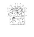
図1に示すように、冷蔵庫10は、本体11を備えている。本体11は、断熱性を有し、前面に開口を有する矩形の箱状に構成されている。冷蔵庫10は、本体11の内部に、食材を貯蔵するための貯蔵室として冷蔵室12、野菜室13、製氷室14、上部冷凍室15、及び下部冷凍室16を備えている。冷蔵室12は、本体11の最上部に設けられている。野菜室13は、冷蔵室12の下方に設けられている。製氷室14及び上部冷凍室15は、野菜室13の下方にあって左右に並べて設けられている。下部冷凍室16は、製氷室14及び上部冷凍室15の下方すなわち本体11の最下部に設けられている。(First embodiment)
As shown in FIG. 1, the
冷蔵庫10は、左側の冷蔵室扉171、右側の冷蔵室扉172、野菜室扉18、製氷室扉19、上部冷凍室扉20、及び下部冷凍室扉21を備えている。左右の冷蔵室扉171、172は、断熱性を有するヒンジ開閉式の扉であって、観音開き式に構成されている。左右の冷蔵室扉171、172は、冷蔵室12の前側に設けられ、冷蔵室12の前側の開口を開閉する。野菜室扉18は、断熱性を有する引き出し式の扉であって、野菜室13の前側に設けられている。野菜室扉18は、野菜室13の前側の開口を開閉する。同様に、製氷室扉19、上部冷凍室扉20、及び下部冷凍室扉21は、それぞれ製氷室14、上部冷凍室15、及び下部冷凍室16の前側に設けられている。これら製氷室扉19、上部冷凍室扉20、及び下部冷凍室扉21は、それぞれ製氷室14、上部冷凍室15、及び下部冷凍室16の前側の開口を開閉する。 The
詳細は図示しないが、野菜室扉18、製氷室扉19、上部冷凍室扉20、及び下部冷凍室扉21には、各貯蔵室側にあって収納容器が設けられている。各収納容器は、野菜室扉18、製氷室扉19、上部冷凍室扉20、又は下部冷凍室扉21の前後方向への出し入れに伴って各貯蔵室内に出し入れされる。 Although details are not shown, the
左側の冷蔵室扉171には、上から順に、上段部のドアポケット22と、中段部のドアポケット23と、下段のドアポケット24とが設けられている。右側の冷蔵室扉172には、上から順に、上段のドアポケット25と、中段部のドアポケット26と、下段部のドアポケット27とが設けられている。これらドアポケット22、23、24、25、26、27には、食材等の貯蔵物が収納される。 The left
中段部のドアポケット26には、カメラ装置設置部28が一体にして設けられている。カメラ装置設置部28は、ドアポケット26において冷蔵庫10の左右方向の中央側に設けられている。カメラ装置30は、カメラ装置設置部28に設置される。これにより、カメラ装置30は、冷蔵庫10の右側の冷蔵室扉172にあって、冷蔵室12の上下方向の中央付近、かつ、冷蔵室12の左右方向の中央付近に取り付けられる。 A camera
この場合、カメラ装置30は、冷蔵庫10とは別に構成されており、冷蔵庫10の構成要素には含まれない。そして、カメラ装置30は、冷蔵庫10に対して取り外し可能に構成されている。この場合、冷蔵庫10を購入した使用者は、別途カメラ装置30を購入し、そのカメラ装置30を事後的に冷蔵庫10に取り付けることができる。カメラ装置設置部28は、冷蔵室12内を撮像する撮像手段たるカメラ装置30が設置される撮像手段設置部として機能する。 In this case, the
なお、カメラ装置設置部28は、ドアポケット26と別体に構成し、冷蔵庫10に予め固定してあってもよい。また、カメラ装置30は、冷蔵庫10の構成要素に含まれていても良い。例えば、カメラ装置30は、冷蔵庫10の右側の冷蔵室扉172固定されたカメラ装置設置部28に予め取り付けられ、冷蔵庫10に対して取り外し不可に構成しても良い。 The camera
カメラ装置30は、図2にも示すように、全体として矩形の箱状に構成されている。カメラ装置30は、詳細は図示しないが、CCD又はCMOS等の撮像素子を有しており、本体11の開口側つまり冷蔵室扉172側から冷蔵室12内の画像を撮像する。カメラ装置30は、レンズ部31と照明部32とを有している。レンズ部31は、120度程度の視野角を有する広角レンズで構成されている。なお、比較例として一般的なWebカメラの場合、その視野角は55度程度である。照明部32は、例えば発光ダイオードなどの光源で構成されている。カメラ装置30は、冷蔵室12内部を撮像する際、照明部32を発光させて冷蔵室12内を照明する。 As shown in FIG. 2, the
カメラ装置30は、レンズ部31が、冷蔵室12の略水平方向の奥方を向く姿勢でカメラ装置設置部28に設置される。カメラ装置30は、レンズ部31及び照明部32カメラ装置設置部28から露出する形態で、カメラ装置設置部28に設置される。この場合、カメラ装置30は、右側の冷蔵室扉172が閉鎖された状態において、冷蔵庫10の前面開口側から視認できる冷蔵室12の内部の略全域の視野を確保している。 The
カメラ装置30は、詳細は図示しないが、静止画又は動画の撮像を制御する制御回路と、撮像した情報を記憶する記憶媒体と、外部との情報通信を行う通信回路と、これらの回路に電源を供給する電池とを有している。カメラ装置30は、図3に示すように、通信装置91やルータ92等と共に、家電ネットワークシステム90を構成する。通信装置91は、冷蔵庫10に予め設けられたものであっても良いし、使用者が事後的に冷蔵庫10に取り付ける構成でも良い。通信装置91は、カメラ装置30とルータ92との間の情報通信を仲介する。ルータ92は、インターネット等の有線又は無線の通信回線93を介して、スマートフォン等の通信端末94やサーバ95に接続される。 Although not shown in detail, the
使用者は、通信端末94を介してカメラ装置30を操作し、これにより冷蔵室12内の撮像を行う。また、カメラ装置30は、使用者の操作によらないで、定期的に撮像するものとしても良い。カメラ装置30によって撮像された画像又は動画は、通信装置91、ルータ92、及び通信回線93を介してサーバ95にアップロードされる。また、カメラ装置30によって撮像された画像又は動画は、通信端末94で直接受信することもできる。使用者は、サーバ95にアップロードされ、又はカメラ装置30から通信回線93を介して直接的に受信した画像又は動画を、通信端末94を通して確認することができる。 The user operates the
図4に示すように、冷蔵庫10は、庫内灯29を備えている。庫内灯29は、冷蔵室12内にあって、冷蔵室12の天井部121に設けられている。庫内灯29は、例えば発光ダイオード等の光源を有し、冷蔵室12内を照明する。冷蔵室12内の最下部には、例えば卵室やチルド室のような特定目的室122が設けられている。冷蔵室12内にあって、特定目的室122の上方には、複数の棚板が設けられている。この場合、冷蔵室12内には、上から順に、上段の棚板41、中段の棚板42、及び下段の棚板43が設けられている。これら棚板41、42、43は、例えばガラスや強化プラスチック等で構成されている。 As shown in FIG. 4, the
冷蔵庫10は、複数の鏡部材、この場合、第1鏡部材51、第2鏡部材52、及び第3鏡部材53を備えている。これら複数の鏡部材51、52、53は、例えばガラスや樹脂製の板又は樹脂製のフィルム等に、鏡面となる金属を蒸着させた一般的な平板状の鏡で構成されている。鏡部材51、52、53は、カメラ装置設置部28に配置されたカメラ装置30の撮像範囲内にあって、カメラ装置30の上方に設けられている。 The
具体的には、第1鏡部材51は、冷蔵室12の天井部121にあって、庫内灯29の前側に設けられている。第2鏡部材52は、上段の棚板41の下面にあって、当該棚板41の略全域に亘って設けられている。第3鏡部材53は、中段の棚板42の下面にあって、当該棚板42の略全域に亘って設けられている。第2鏡部材52は、上段の棚板41に鏡面となる金属を直接蒸着するなどして、上段の棚板41と一体に形成しても良い。同様に、第3鏡部材53も、中段の棚板42に鏡面となる金属を直接蒸着するなどして、中段の棚板42と一体に形成しても良い。 Specifically, the
図5に示すように、各鏡部材51、52、53の鏡面511、521、531が鉛直方向に直角な姿勢すなわち水平状態を0°とし、鉛直方向に平行な姿勢すなわち鉛直状態を90°とした場合、鏡面511、521、531と水平面との成す角θは、0°≦θ<90°の範囲で定められている。この場合、θ=0°であり、各鏡部材51、52、53の姿勢は、略水平状態となっている。すなわち、図4に示すように、各鏡部材51、52、53の鏡面511、521、531は下方を向いている。 As shown in FIG. 5, the mirror surfaces 511, 521, and 531 of the
図4の一点鎖線Aは、カメラ装置設置部28に配置されたカメラ装置30の撮像範囲を示している。二点鎖線B1は、第1鏡部材51の反射により、カメラ装置30が撮像可能となる範囲を示している。二点鎖線B2は、第2鏡部材52の反射により、カメラ装置30が撮像可能となる範囲を示している。そして、二点鎖線B3は、第3鏡部材53の反射により、カメラ装置30が撮像可能となる範囲を示している。このように、鏡部材51、52、53は、その反射によって、カメラ装置30の撮像範囲を、通常の撮像範囲では死角となる各棚板41、42、43の奥方まで拡大する。 An alternate long and short dash line A in FIG. 4 indicates an imaging range of the
図6は、カメラ装置30によって撮像された冷蔵室12内の画像を示している。冷蔵室12内には、複数の貯蔵物が収納されている。これら複数の貯蔵物のうち、カメラ装置30から直接見える貯蔵物を、貯蔵物81で示している。一方、貯蔵物81に隠れてカメラ装置30からは直接見ることができない貯蔵物を、貯蔵物82で示している。本実施形態に構成によれば、貯蔵物81に隠れた貯蔵物82の像は、各鏡部材51、52、53に反射してカメラ装置30へ届く。そのため、カメラ装置30は、各鏡部材51、52、53に反射した貯蔵物82の像を撮像することができる。 FIG. 6 shows an image in the
すなわち、この構成によれば、各鏡部材51、52、53によって、カメラ装置30の撮像範囲を広げることができる。その結果、1台のカメラ装置30によって冷蔵室12内の広範囲を撮像することができ、貯蔵室たる冷蔵室12内の貯蔵物を正確に把握することができる。したがって、カメラ装置30を動かして撮像範囲を変更したり、複数台のカメラ装置30を用いたりする必要がないため、低コストで正確に貯蔵室12内を撮像し、貯蔵物を把握することができる。 That is, according to this configuration, the imaging range of the
(第二実施形態)
次に、第二実施形態について、図7を参照して説明する。第二実施形態において、冷蔵庫10は、鏡部材として第4鏡部材54、第5鏡部材55、及び第6鏡部材56を備えている。これら鏡部材54、55、56の構成は、第一実施形態の鏡部材51、52、53と同様である。第4鏡部材54は、冷蔵室12の天井部121にあって、庫内灯29の前側に設けられている。第5鏡部材55は、中段の棚板42の前端部に設けられている。第6鏡部材56は、中段の棚板42の下面側の後端部に設けられている。第4鏡部材54及び第5鏡部材55は、カメラ装置30の上方に設けられている。第6鏡部材56は、カメラ装置30の高さ位置と略同じ高さ位置に設けられている。各鏡部材54、55、56は、その鏡面が、前方下方へ向いている。すなわち、各鏡部材51、52、53と水平面とのなす角θは、0°<θ<90°の範囲で定められている。(Second embodiment)
Next, a second embodiment will be described with reference to FIG. In the second embodiment, the
二点鎖線B4は、第4鏡部材54の反射により、カメラ装置30が撮像可能となる範囲を示している。二点鎖線B5は、第5鏡部材55の反射により、カメラ装置30が撮像可能となる範囲を示している。そして、二点鎖線B6は、第6鏡部材56の反射により、カメラ装置30が撮像可能となる範囲を示している。この場合、第4鏡部材54は、その反射によって、カメラ装置30の撮像範囲を、通常の撮像範囲では死角となる上段部のドアポケット22、25の範囲まで拡大する。第5鏡部材55は、その反射によって、カメラ装置30の撮像範囲を、通常の撮像範囲では死角となる下段部のドアポケット24、27の範囲まで拡大する。そして、第6鏡部材56は、その反射によって、カメラ装置30の撮像範囲を、通常の撮像範囲では死角となる下段の棚板43の上側後部まで拡大する。 An alternate long and two short dashes line B <b> 4 indicates a range in which the
これによれば、第一実施形態と同様の作用効果が得られる。さらに、カメラ装置30は、当該カメラ装置30の撮像範囲から外れた左右の冷蔵室扉171、172側についても撮像することができる。すなわち、カメラ装置30の撮像範囲をより広範囲に広げることができる。その結果、1台のカメラ装置30によって冷蔵室12内のより広範囲を撮像することができ、貯蔵室たる冷蔵室12内の貯蔵物を正確に把握することができる。したがって、カメラ装置30を動かして撮像範囲を変更したり、複数台のカメラ装置30を用いたりする必要がないため、より低コストで正確に貯蔵室12内を撮像し、貯蔵物を把握することができる。 According to this, the effect similar to 1st embodiment is acquired. Furthermore, the
(第三実施形態)
次に、第三実施形態について、図8を参照して説明する。第三実施形態において、冷蔵庫10は、鏡部材として第7鏡部材57、第8鏡部材58、及び第9鏡部材59を備えている。第7鏡部材57は、冷蔵室12の天井部121にあって、庫内灯29の前側に設けられている。第8鏡部材58は、中段の棚板42の下面側に設けられている。第9鏡部材59は、中段の棚板42の下面側の後端部に設けられている。第7鏡部材57及び第8鏡部材58は、カメラ装置30の上方に設けられている。第9鏡部材59は、カメラ装置30の高さ位置と略同じ高さ位置に設けられている。これら第7鏡部材57、第8鏡部材58、及び第9鏡部材59は、鏡面が曲面形状に湾曲して形成された、いわゆる曲面鏡で構成されている。(Third embodiment)
Next, a third embodiment will be described with reference to FIG. In the third embodiment, the
二点鎖線B7は、第7鏡部材57の反射により、カメラ装置30が撮像可能となる範囲を示している。二点鎖線B8は、第8鏡部材58の反射により、カメラ装置30が撮像可能となる範囲を示している。そして、二点鎖線B9は、第9鏡部材59の反射により、カメラ装置30が撮像可能となる範囲を示している。一般に、曲面鏡は、平面鏡に比べて反射可能な範囲が広い。この場合、第7鏡部材57は、その反射によって、カメラ装置30の撮像範囲を、上段の棚板41の上側後部、及び上段部のドアポケット22、25の範囲まで拡大する。第8鏡部材58は、その反射によって、カメラ装置30の撮像範囲を、中段の棚板42の上側後部、及び下段部のドアポケット24、27の範囲まで拡大する。そして、第9鏡部材59は、その反射によって、カメラ装置30の撮像範囲を、下段の棚板43の上側後部まで拡大する。 An alternate long and two short dashes line B <b> 7 indicates a range in which the
これによれば、第一実施形態と同様の作用効果が得られる。さらに、カメラ装置30は、当該カメラ装置30の撮像範囲から外れた左右の冷蔵室扉171、172側についても撮像することができる。すなわち、各鏡部材57、58、59に平面鏡を採用した場合に比べて、カメラ装置30の撮像範囲をさらに広範囲に広げることができる。その結果、1台のカメラ装置30によって冷蔵室12内のより広範囲を撮像することができ、貯蔵室たる冷蔵室12内の貯蔵物を正確に把握することができる。 According to this, the effect similar to 1st embodiment is acquired. Furthermore, the
なお、庫内灯29と各鏡部材の位置関係は特に限定されない。例えば庫内灯29は、第1鏡部材51又は第4鏡部材54又は第7鏡部材57の前側にあっても良い。野菜室13、上部冷凍室15、又は下部冷凍室16に、鏡部材を設けても良い。カメラ装置設置部28は、左側の冷蔵室扉171に設けても良く、冷蔵室12の左右又は背部の内壁に設けても良い。 The positional relationship between the
以上説明した実施形態の冷蔵庫は、貯蔵物を貯蔵する貯蔵室と、前記貯蔵室内を撮像する撮像手段が設置される撮像手段設置部と、前記撮像手段設置部に設置される撮像手段の撮像範囲内にあって前記撮像手段と同じ高さ位置又は前記撮像手段の上方に設けられた鏡と、を備えている。これによれば、前記鏡の反射によって、前記撮像手段の撮像範囲を広げることができる。したがって、1台の撮像手段によって貯蔵室内の広範囲を撮像することができ、貯蔵室内の貯蔵物を正確に把握することができる。そのため、撮像手段を動かして撮像範囲を変更したり、複数の撮像手段を用いたりする必要がないため、低コストで正確に貯蔵室内を撮像し、貯蔵物を把握することができる。 The refrigerator of the embodiment described above includes a storage room for storing stored items, an imaging means installation unit in which an imaging unit for imaging the storage room is installed, and an imaging range of the imaging unit installed in the imaging unit installation unit. And a mirror provided at the same height as the image pickup means or above the image pickup means. According to this, the imaging range of the imaging means can be expanded by the reflection of the mirror. Therefore, a wide range in the storage room can be imaged by one imaging means, and the stored items in the storage room can be accurately grasped. Therefore, there is no need to move the imaging means to change the imaging range or use a plurality of imaging means, so that the storage room can be accurately imaged and the stored items can be grasped at low cost.
本発明のいくつかの実施形態を説明したが、これらの実施形態は、例として提示したものであり、発明の範囲を限定することは意図していない。これら新規な実施形態は、その他の様々な形態で実施されることが可能であり、発明の要旨を逸脱しない範囲で、種々の省略、置き換え、変更を行うことができる。これら実施形態やその変更は、発明の範囲や要旨に含まれるとともに、特許請求の範囲に記載された発明とその均等の範囲に含まれる。 Although several embodiments of the present invention have been described, these embodiments are presented by way of example and are not intended to limit the scope of the invention. These novel embodiments can be implemented in various other forms, and various omissions, replacements, and changes can be made without departing from the scope of the invention. These embodiments and modifications thereof are included in the scope and gist of the invention, and are included in the invention described in the claims and equivalents thereof.
図面中、10は冷蔵庫、12は冷蔵室(貯蔵室)、121は天井部、13は野菜室(貯蔵室)、14は製氷室(貯蔵室)、15は上部冷凍室(貯蔵室)、16は下部冷凍室(貯蔵室)、171は左側の冷蔵室扉(扉)、172は右側の冷蔵室扉(扉)、18は野菜室扉(扉)、19は製氷室扉(扉)、20は上部冷凍室扉(扉)、21は下部冷凍室扉(扉)、28はカメラ装置設置部(撮像手段設置部)、30はカメラ装置(撮像手段)、41は上段の棚板(棚板)、42は中段の棚板(棚板)、43は下段の棚板(棚板)、51は第1鏡部材(鏡部材)、511は鏡面、52は第2鏡部材(鏡部材)、521は鏡面、53は第3鏡部材(鏡部材)、531は鏡面、54は第4鏡部材(鏡部材)、55は第5鏡部材(鏡部材)、56は第6鏡部材(鏡部材)、57は第7鏡部材(鏡部材)、58は第8鏡部材(鏡部材)、59は第9鏡部材(鏡部材)、81、82は貯蔵物を示す。 In the drawings, 10 is a refrigerator, 12 is a refrigerator room (storage room), 121 is a ceiling, 13 is a vegetable room (storage room), 14 is an ice making room (storage room), 15 is an upper freezer room (storage room), 16 Is a lower freezer compartment (storage room), 171 is a left refrigerator compartment door (door), 172 is a right refrigerator compartment door (door), 18 is a vegetable compartment door (door), 19 is an ice making compartment door (door), 20 Is an upper freezer compartment door (door), 21 is a lower freezer compartment door (door), 28 is a camera device installation part (imaging means installation part), 30 is a camera device (imaging means), and 41 is an upper shelf (shelf). ), 42 is a middle shelf (shelf), 43 is a lower shelf (shelf), 51 is a first mirror member (mirror member), 511 is a mirror surface, 52 is a second mirror member (mirror member), 521 is a mirror surface, 53 is a third mirror member (mirror member), 531 is a mirror surface, 54 is a fourth mirror member (mirror member), 55 is a fifth mirror member (mirror member), and 56 is a sixth mirror. Material (mirror member), a seventh mirror member (mirror member) 57, eighth mirror member (mirror member) is 58, the ninth mirror member (mirror member) 59, 81 and 82 show the reservoir.
Claims (5)
Translated fromJapanese前記貯蔵室内を撮像する撮像手段が設置される撮像手段設置部と、
前記撮像手段設置部に設置される撮像手段の撮像範囲内にあって前記撮像手段と同じ高さ位置又は前記撮像手段の上方に設けられた鏡部材と、
を備える冷蔵庫。A storage room for storing stored items;
An imaging means installation section in which imaging means for imaging the storage chamber is installed;
A mirror member provided within the imaging range of the imaging means installed in the imaging means installation unit and provided at the same height position as the imaging means or above the imaging means;
Refrigerator.
前記鏡部材は、前記棚板の下面に設けられている請求項1から3のいずれか一項に記載の冷蔵庫。It is a shelf plate that is provided in the storage chamber and on which stored items are placed, and includes a shelf plate that is positioned above the imaging unit in a state where the imaging unit is installed in the imaging unit installation unit,
The refrigerator according to any one of claims 1 to 3, wherein the mirror member is provided on a lower surface of the shelf board.
Priority Applications (1)
| Application Number | Priority Date | Filing Date | Title |
|---|---|---|---|
| JP2013120790AJP2014238217A (en) | 2013-06-07 | 2013-06-07 | Refrigerator |
Applications Claiming Priority (1)
| Application Number | Priority Date | Filing Date | Title |
|---|---|---|---|
| JP2013120790AJP2014238217A (en) | 2013-06-07 | 2013-06-07 | Refrigerator |
Publications (1)
| Publication Number | Publication Date |
|---|---|
| JP2014238217Atrue JP2014238217A (en) | 2014-12-18 |
Family
ID=52135500
Family Applications (1)
| Application Number | Title | Priority Date | Filing Date |
|---|---|---|---|
| JP2013120790APendingJP2014238217A (en) | 2013-06-07 | 2013-06-07 | Refrigerator |
Country Status (1)
| Country | Link |
|---|---|
| JP (1) | JP2014238217A (en) |
Cited By (5)
| Publication number | Priority date | Publication date | Assignee | Title |
|---|---|---|---|---|
| JP2017032158A (en)* | 2015-07-29 | 2017-02-09 | シャープ株式会社 | Storage box |
| JP2021009008A (en)* | 2019-07-03 | 2021-01-28 | シャープ株式会社 | refrigerator |
| WO2021250913A1 (en)* | 2020-06-09 | 2021-12-16 | 日立グローバルライフソリューションズ株式会社 | Refrigerator and output device |
| JP2022176288A (en)* | 2018-06-29 | 2022-11-25 | シャープ株式会社 | refrigerator |
| WO2023146264A1 (en)* | 2022-01-26 | 2023-08-03 | 비스타테크놀러지 주식회사 | System and method for managing product inventory by using reflector-camera structure |
Citations (5)
| Publication number | Priority date | Publication date | Assignee | Title |
|---|---|---|---|---|
| JP2000244906A (en)* | 1999-02-19 | 2000-09-08 | Electrolux:Ab | System and method for obtaining information on contents in cabinet |
| US20030164754A1 (en)* | 2000-08-18 | 2003-09-04 | Rutger Roseen | Method and apparatus for keeping a check on the storage time for goods in a storage |
| JP2006084132A (en)* | 2004-09-16 | 2006-03-30 | Mitsubishi Electric Corp | Sensor device, door device, refrigerator |
| JP2007046834A (en)* | 2005-08-09 | 2007-02-22 | Funai Electric Co Ltd | Article storage, article storage monitoring system and refrigerator monitoring system |
| JP2013024491A (en)* | 2011-07-22 | 2013-02-04 | Panasonic Corp | Refrigerator |
- 2013
- 2013-06-07JPJP2013120790Apatent/JP2014238217A/enactivePending
Patent Citations (5)
| Publication number | Priority date | Publication date | Assignee | Title |
|---|---|---|---|---|
| JP2000244906A (en)* | 1999-02-19 | 2000-09-08 | Electrolux:Ab | System and method for obtaining information on contents in cabinet |
| US20030164754A1 (en)* | 2000-08-18 | 2003-09-04 | Rutger Roseen | Method and apparatus for keeping a check on the storage time for goods in a storage |
| JP2006084132A (en)* | 2004-09-16 | 2006-03-30 | Mitsubishi Electric Corp | Sensor device, door device, refrigerator |
| JP2007046834A (en)* | 2005-08-09 | 2007-02-22 | Funai Electric Co Ltd | Article storage, article storage monitoring system and refrigerator monitoring system |
| JP2013024491A (en)* | 2011-07-22 | 2013-02-04 | Panasonic Corp | Refrigerator |
Cited By (8)
| Publication number | Priority date | Publication date | Assignee | Title |
|---|---|---|---|---|
| JP2017032158A (en)* | 2015-07-29 | 2017-02-09 | シャープ株式会社 | Storage box |
| JP2022176288A (en)* | 2018-06-29 | 2022-11-25 | シャープ株式会社 | refrigerator |
| JP7594569B2 (en) | 2018-06-29 | 2024-12-04 | シャープ株式会社 | refrigerator |
| JP2024177521A (en)* | 2018-06-29 | 2024-12-19 | シャープ株式会社 | refrigerator |
| JP2021009008A (en)* | 2019-07-03 | 2021-01-28 | シャープ株式会社 | refrigerator |
| JP7297563B2 (en) | 2019-07-03 | 2023-06-26 | シャープ株式会社 | refrigerator |
| WO2021250913A1 (en)* | 2020-06-09 | 2021-12-16 | 日立グローバルライフソリューションズ株式会社 | Refrigerator and output device |
| WO2023146264A1 (en)* | 2022-01-26 | 2023-08-03 | 비스타테크놀러지 주식회사 | System and method for managing product inventory by using reflector-camera structure |
Similar Documents
| Publication | Publication Date | Title |
|---|---|---|
| JP6371965B2 (en) | Refrigerator and refrigerator system | |
| JP6359179B2 (en) | refrigerator | |
| JP2014238217A (en) | Refrigerator | |
| TWI642886B (en) | Refrigerator and camera system thereof | |
| JP2016183826A (en) | Imaging unit and refrigerator | |
| JP6494946B2 (en) | refrigerator | |
| JP2016023892A (en) | refrigerator | |
| JP6167330B2 (en) | Refrigerator and refrigerator system | |
| JP2014196845A (en) | Refrigerator and refrigerator system | |
| CN111133265A (en) | Digital camera and domestic refrigeration appliance with digital camera | |
| JP6167327B2 (en) | refrigerator | |
| JP6485678B2 (en) | Refrigerator and refrigerator system | |
| JP6681555B2 (en) | refrigerator | |
| JP2014196842A (en) | Refrigerator and refrigerator system | |
| JP6201142B2 (en) | refrigerator | |
| CN111108334A (en) | Home refrigeration appliance with digital camera | |
| JP6641109B2 (en) | refrigerator | |
| JP6307699B2 (en) | Refrigerator and display system in refrigerator | |
| JP6283814B2 (en) | Refrigerator and display system in refrigerator | |
| JP6114916B2 (en) | refrigerator | |
| JP6167329B2 (en) | refrigerator | |
| JP2020094801A (en) | refrigerator | |
| JP6167328B2 (en) | refrigerator | |
| JP6145701B2 (en) | refrigerator | |
| JP6145702B2 (en) | refrigerator |
Legal Events
| Date | Code | Title | Description |
|---|---|---|---|
| A621 | Written request for application examination | Free format text:JAPANESE INTERMEDIATE CODE: A621 Effective date:20160517 | |
| A711 | Notification of change in applicant | Free format text:JAPANESE INTERMEDIATE CODE: A711 Effective date:20160629 | |
| A131 | Notification of reasons for refusal | Free format text:JAPANESE INTERMEDIATE CODE: A131 Effective date:20170321 | |
| A977 | Report on retrieval | Free format text:JAPANESE INTERMEDIATE CODE: A971007 Effective date:20170322 | |
| A521 | Request for written amendment filed | Free format text:JAPANESE INTERMEDIATE CODE: A523 Effective date:20170516 | |
| A02 | Decision of refusal | Free format text:JAPANESE INTERMEDIATE CODE: A02 Effective date:20171010 | |
| A521 | Request for written amendment filed | Free format text:JAPANESE INTERMEDIATE CODE: A523 Effective date:20180109 | |
| A911 | Transfer to examiner for re-examination before appeal (zenchi) | Free format text:JAPANESE INTERMEDIATE CODE: A911 Effective date:20180117 | |
| A912 | Re-examination (zenchi) completed and case transferred to appeal board | Free format text:JAPANESE INTERMEDIATE CODE: A912 Effective date:20180309 |