JP2014237025A - Capacitive sensing method and device for detecting skin - Google Patents
Capacitive sensing method and device for detecting skinDownload PDFInfo
- Publication number
- JP2014237025A JP2014237025AJP2014159520AJP2014159520AJP2014237025AJP 2014237025 AJP2014237025 AJP 2014237025AJP 2014159520 AJP2014159520 AJP 2014159520AJP 2014159520 AJP2014159520 AJP 2014159520AJP 2014237025 AJP2014237025 AJP 2014237025A
- Authority
- JP
- Japan
- Prior art keywords
- skin
- dermatological treatment
- bezel
- treatment device
- capacitance
- Prior art date
- Legal status (The legal status is an assumption and is not a legal conclusion. Google has not performed a legal analysis and makes no representation as to the accuracy of the status listed.)
- Pending
Links
- 238000000034methodMethods0.000titleabstractdescription22
- 238000011282treatmentMethods0.000claimsabstractdescription87
- 230000008859changeEffects0.000claimsabstractdescription10
- 238000001514detection methodMethods0.000claimsdescription6
- 230000003716rejuvenationEffects0.000claims1
- 239000003990capacitorSubstances0.000abstractdescription14
- 230000004913activationEffects0.000abstractdescription6
- 230000005670electromagnetic radiationEffects0.000description6
- 239000000463materialSubstances0.000description5
- 230000035945sensitivityEffects0.000description4
- 239000004642PolyimideSubstances0.000description3
- XECAHXYUAAWDEL-UHFFFAOYSA-Nacrylonitrile butadiene styreneChemical compoundC=CC=C.C=CC#N.C=CC1=CC=CC=C1XECAHXYUAAWDEL-UHFFFAOYSA-N0.000description3
- 229920000122acrylonitrile butadiene styrenePolymers0.000description3
- 239000004676acrylonitrile butadiene styreneSubstances0.000description3
- 230000008901benefitEffects0.000description3
- 238000013461designMethods0.000description3
- 238000010586diagramMethods0.000description3
- 239000011521glassSubstances0.000description3
- 229920001721polyimidePolymers0.000description3
- 208000002874Acne VulgarisDiseases0.000description2
- 206010000496acneDiseases0.000description2
- NIXOWILDQLNWCW-UHFFFAOYSA-Nacrylic acid groupChemical groupC(C=C)(=O)ONIXOWILDQLNWCW-UHFFFAOYSA-N0.000description2
- 239000004020conductorSubstances0.000description2
- 239000003989dielectric materialSubstances0.000description2
- 239000012528membraneSubstances0.000description2
- 239000002184metalSubstances0.000description2
- 230000003287optical effectEffects0.000description2
- 239000004417polycarbonateSubstances0.000description2
- 229920000515polycarbonatePolymers0.000description2
- 238000012545processingMethods0.000description2
- 230000037303wrinklesEffects0.000description2
- 201000004384AlopeciaDiseases0.000description1
- 201000004569BlindnessDiseases0.000description1
- 229920004943Delrin®Polymers0.000description1
- 239000004419PanliteSubstances0.000description1
- 206010057430Retinal injuryDiseases0.000description1
- 208000027418Wounds and injuryDiseases0.000description1
- DHKHKXVYLBGOIT-UHFFFAOYSA-Nacetaldehyde Diethyl AcetalNatural productsCCOC(C)OCCDHKHKXVYLBGOIT-UHFFFAOYSA-N0.000description1
- 125000002777acetyl groupChemical class[H]C([H])([H])C(*)=O0.000description1
- 230000005540biological transmissionEffects0.000description1
- 238000004891communicationMethods0.000description1
- 239000000356contaminantSubstances0.000description1
- 238000001816coolingMethods0.000description1
- 230000006378damageEffects0.000description1
- 230000035614depigmentationEffects0.000description1
- 238000010891electric arcMethods0.000description1
- 231100000040eye damageToxicity0.000description1
- 239000012530fluidSubstances0.000description1
- 230000004907fluxEffects0.000description1
- 230000003779hair growthEffects0.000description1
- 208000024963hair lossDiseases0.000description1
- 230000003676hair lossEffects0.000description1
- 230000002401inhibitory effectEffects0.000description1
- 208000014674injuryDiseases0.000description1
- 238000009413insulationMethods0.000description1
- 238000004519manufacturing processMethods0.000description1
- 238000005259measurementMethods0.000description1
- 230000007246mechanismEffects0.000description1
- 239000000203mixtureSubstances0.000description1
- 230000008569processEffects0.000description1
- 230000001737promoting effectEffects0.000description1
- 230000005855radiationEffects0.000description1
- 230000004044responseEffects0.000description1
- 238000012552reviewMethods0.000description1
- 238000002604ultrasonographyMethods0.000description1
- XLYOFNOQVPJJNP-UHFFFAOYSA-NwaterSubstancesOXLYOFNOQVPJJNP-UHFFFAOYSA-N0.000description1
Images

Classifications
- A—HUMAN NECESSITIES
- A61—MEDICAL OR VETERINARY SCIENCE; HYGIENE
- A61B—DIAGNOSIS; SURGERY; IDENTIFICATION
- A61B18/00—Surgical instruments, devices or methods for transferring non-mechanical forms of energy to or from the body
- A61B18/18—Surgical instruments, devices or methods for transferring non-mechanical forms of energy to or from the body by applying electromagnetic radiation, e.g. microwaves
- A61B18/20—Surgical instruments, devices or methods for transferring non-mechanical forms of energy to or from the body by applying electromagnetic radiation, e.g. microwaves using laser
- A61B18/203—Surgical instruments, devices or methods for transferring non-mechanical forms of energy to or from the body by applying electromagnetic radiation, e.g. microwaves using laser applying laser energy to the outside of the body
- A—HUMAN NECESSITIES
- A61—MEDICAL OR VETERINARY SCIENCE; HYGIENE
- A61N—ELECTROTHERAPY; MAGNETOTHERAPY; RADIATION THERAPY; ULTRASOUND THERAPY
- A61N5/00—Radiation therapy
- A61N5/06—Radiation therapy using light
- A61N5/0613—Apparatus adapted for a specific treatment
- A61N5/0616—Skin treatment other than tanning
- A—HUMAN NECESSITIES
- A61—MEDICAL OR VETERINARY SCIENCE; HYGIENE
- A61B—DIAGNOSIS; SURGERY; IDENTIFICATION
- A61B18/00—Surgical instruments, devices or methods for transferring non-mechanical forms of energy to or from the body
- A61B18/18—Surgical instruments, devices or methods for transferring non-mechanical forms of energy to or from the body by applying electromagnetic radiation, e.g. microwaves
- A61B18/20—Surgical instruments, devices or methods for transferring non-mechanical forms of energy to or from the body by applying electromagnetic radiation, e.g. microwaves using laser
- A—HUMAN NECESSITIES
- A61—MEDICAL OR VETERINARY SCIENCE; HYGIENE
- A61B—DIAGNOSIS; SURGERY; IDENTIFICATION
- A61B18/00—Surgical instruments, devices or methods for transferring non-mechanical forms of energy to or from the body
- A61B2018/00315—Surgical instruments, devices or methods for transferring non-mechanical forms of energy to or from the body for treatment of particular body parts
- A61B2018/00452—Skin
- A—HUMAN NECESSITIES
- A61—MEDICAL OR VETERINARY SCIENCE; HYGIENE
- A61B—DIAGNOSIS; SURGERY; IDENTIFICATION
- A61B18/00—Surgical instruments, devices or methods for transferring non-mechanical forms of energy to or from the body
- A61B2018/00636—Sensing and controlling the application of energy
- A—HUMAN NECESSITIES
- A61—MEDICAL OR VETERINARY SCIENCE; HYGIENE
- A61B—DIAGNOSIS; SURGERY; IDENTIFICATION
- A61B90/00—Instruments, implements or accessories specially adapted for surgery or diagnosis and not covered by any of the groups A61B1/00 - A61B50/00, e.g. for luxation treatment or for protecting wound edges
- A61B90/06—Measuring instruments not otherwise provided for
- A61B2090/064—Measuring instruments not otherwise provided for for measuring force, pressure or mechanical tension
- A61B2090/065—Measuring instruments not otherwise provided for for measuring force, pressure or mechanical tension for measuring contact or contact pressure
- A—HUMAN NECESSITIES
- A61—MEDICAL OR VETERINARY SCIENCE; HYGIENE
- A61N—ELECTROTHERAPY; MAGNETOTHERAPY; RADIATION THERAPY; ULTRASOUND THERAPY
- A61N5/00—Radiation therapy
- A61N5/06—Radiation therapy using light
- A61N2005/0635—Radiation therapy using light characterised by the body area to be irradiated
- A61N2005/0643—Applicators, probes irradiating specific body areas in close proximity
- A61N2005/0644—Handheld applicators
- A—HUMAN NECESSITIES
- A61—MEDICAL OR VETERINARY SCIENCE; HYGIENE
- A61N—ELECTROTHERAPY; MAGNETOTHERAPY; RADIATION THERAPY; ULTRASOUND THERAPY
- A61N5/00—Radiation therapy
- A61N5/06—Radiation therapy using light
- A61N5/0613—Apparatus adapted for a specific treatment
- A61N5/0616—Skin treatment other than tanning
- A61N5/0617—Hair treatment
Landscapes
- Health & Medical Sciences (AREA)
- Life Sciences & Earth Sciences (AREA)
- Physics & Mathematics (AREA)
- Engineering & Computer Science (AREA)
- Biomedical Technology (AREA)
- Nuclear Medicine, Radiotherapy & Molecular Imaging (AREA)
- Optics & Photonics (AREA)
- Surgery (AREA)
- Animal Behavior & Ethology (AREA)
- General Health & Medical Sciences (AREA)
- Public Health (AREA)
- Veterinary Medicine (AREA)
- Electromagnetism (AREA)
- Biophysics (AREA)
- Pathology (AREA)
- Otolaryngology (AREA)
- Radiology & Medical Imaging (AREA)
- Heart & Thoracic Surgery (AREA)
- Medical Informatics (AREA)
- Molecular Biology (AREA)
- Radiation-Therapy Devices (AREA)
- Measurement Of Length, Angles, Or The Like Using Electric Or Magnetic Means (AREA)
- Surgical Instruments (AREA)
- Laser Surgery Devices (AREA)
Abstract
Description
Translated fromJapanese本発明は、皮膚科治療のための皮膚接触センサを含む装置及び方法に関する。より詳しくは、ヒトの皮膚の近接を検知する皮膚科装置の静電容量型センサに関する。 The present invention relates to an apparatus and method including a skin contact sensor for dermatological treatment. More specifically, the present invention relates to a capacitive sensor of a dermatological apparatus that detects the proximity of human skin.
関連出願
本願は以下の米国特許出願の利益に関連し、かつ当該利益を主張する。当該米国特許出願のすべては本出願人が所有し、参照として完全に組み込まれる。
2004年2月19日出願の米国特許出願第10/783,603号(発明の名称:「Eye-Safe Dermatologic Treatment Apparatus And Method」、発明者:Robert E. Grove、Mark V. Weckwerth、及びTobin C. Island);2004年2月19日出願の米国特許出願第10/783,607号(現在、本出願人の米国特許第7,118,563号、発明の名称:「Self-Contained, Diode-Laser-Based Dermatologic Treatment Apparatus and Method」)の継続出願である2006年10月10日出願の米国特許出願第11/545,963号;2004年2月19日出願の米国特許出願第10/783,880号(現在、米国特許第7,250,045号、発明の名称:「Self- Contained Eye-Safe Hair-Regrowth-lnhibitionApparatus And Method」、発明者:Tobin C. Island、Robert E. Grove、及びMark V. Weckwerth)の分割出願である2007年7月27日出願の米国特許出願第11/829,747号;2004年2月25日出願の米国特許出願第10/787,720号(発明の名称:「Optical Sensor and Method for Identifying the Presence of Skin」);2004年3月5日出願の米国特許出願第10/794,504(発明の名称:「Method and Device for Sensing Skin Contact」);及び2007年8月8日出願であり発明の名称及び発明者が本願と同じである米国仮特許出願第60/954,682号。次に、上記特許出願は以下の仮特許出願の1つ以上の利益を主張し、これらもまた参照として組み込まれる。米国仮特許出願第60/451,091号(2003年2月28日出願);第60/456,379号(2003年3月20日出願);第60/458,861号(2003年3月27日出願);第60/472,056号(2003年5月20日出願);第60/450,243号(2003年2月25日出願);第60/450,598号(2003年2月26日出願);第60/452,304号(2003年3月4日出願);第60/451,981号(2003年3月4日出願);第60/452,591号(2003年3月6日出願);及び第60/456,586号(2003年3月21日出願)。これらのすべては本出願人が譲受している。Related Applications This application is related to and claims the benefit of the following US patent applications: All such US patent applications are owned by the Applicant and are fully incorporated by reference.
US patent application Ser. No. 10 / 783,603, filed Feb. 19, 2004 (invention: “Eye-Safe Dermatologic Treatment Apparatus And Method”, inventors: Robert E. Grove, Mark V. Weckwerth, and Tobin C Island); US patent application Ser. No. 10 / 783,607 filed Feb. 19, 2004 (currently US Pat. No. 7,118,563 of the present applicant, title of invention: “Self-Contained, Diode- US patent application Ser. No. 11 / 545,963, filed Oct. 10, 2006, which is a continuation of “Laser-Based Dermatologic Treatment Apparatus and Method”); US Patent Application No. 10/783, filed Feb. 19, 2004; 880 (currently US Pat. No. 7,250,045, title: “Self-Contained Eye-Safe Hair-Regrowth-lnhibition Apparatus And Method”, inventors: Tobin C. Island, Robert E. Grove, and Mark V. Weckwerth) 20 divisional application U.S. Patent Application No. 11 / 829,747 filed July 27, 2007; U.S. Patent Application No. 10 / 787,720 filed February 25, 2004 (Title of Invention: "Optical Sensor and Method for Identifying the Presence of Skin "); US patent application Ser. No. 10 / 794,504 filed Mar. 5, 2004 (invention name:“ Method and Device for Sensing Skin Contact ”); and filed August 8, 2007, invention US Provisional Patent Application No. 60 / 954,682, whose title and inventor are the same as the present application. The above patent application then claims one or more of the following provisional patent applications, which are also incorporated by reference. US Provisional Patent Application No. 60 / 451,091 (filed Feb. 28, 2003); 60 / 456,379 (filed Mar. 20, 2003); 60 / 458,861 (March 2003) No. 60 / 472,056 (filed on May 20, 2003); No. 60 / 450,243 (filed on Feb. 25, 2003); No. 60 / 450,598 (2003 2) No. 60 / 452,304 (filed on Mar. 4, 2003); No. 60 / 451,981 (filed on Mar. 4, 2003); No. 60 / 452,591 (2003) No. 60 / 456,586 (filed Mar. 21, 2003); All of these are assigned by the applicant.
多くの皮膚治療装置では、安全上及び/又は効率上、当該装置のアクティブ領域と当該皮膚との接触が必要となる。 Many skin treatment devices require contact between the active area of the device and the skin for safety and / or efficiency.
例えば、光を用いた除毛システムにおいては、当該光エネルギーが皮膚と接触する透明表面を介して送られるのが通例である。当該システムでは、装置のアクティブ領域が発光表面であり、当該表面と当該被治療皮膚の領域との接触が、治療領域への光の良好な伝達確保の目的と、さもなければ当該装置の目の安全性に応じて目の障害をもたらしかねない迷走光をなくして目の安全を促進する目的との双方にとって望ましい。同時に、発光表面を皮膚に押し当てて当該皮膚を相当程度変形させる必要がないシステムを得ることが望ましい。 For example, in a hair removal system using light, the light energy is typically sent through a transparent surface that contacts the skin. In the system, the active area of the device is a light emitting surface, and the contact between the surface and the area of the skin to be treated is intended to ensure good transmission of light to the treatment area, otherwise the eye of the apparatus. It is desirable both for the purpose of promoting eye safety by eliminating stray light that can cause eye damage depending on safety. At the same time, it is desirable to have a system that does not require the luminescent surface to be pressed against the skin to deform the skin to a considerable extent.
皮膚接触が必要な治療装置の他例には、(1)皮膚冷却は不要だが迷走光防止用接触バッフルを有する紫外線イルミネータのように光の漏れを防止するためにのみ接触が必要な装置、又は(2)皮膚への直接伝導により熱パルスを送る熱ヒータのように動作メカニズムのためにのみ接触が必要であり光の漏れを防止する必要はない装置が含まれる。皮膚接触を含む他の皮膚科装置及び方法には、しわ取りのような超音波及び高周波アプリケーションが含まれる。超音波ジェル、オイル、水、又は屈折率整合流体のような界面材料を介して皮膚接触を与える皮膚科装置及び方法もある。なお、当該装置及び方法はそれでも、当該アプリケーションを目的として皮膚接触が行われるとみなされている。 Other examples of treatment devices that require skin contact include: (1) devices that do not require skin cooling but that need contact only to prevent light leakage, such as ultraviolet illuminators that have a contact baffle to prevent stray light, or (2) Includes devices that need contact only for the operating mechanism and do not need to prevent light leakage, such as a heater that sends heat pulses by direct conduction to the skin. Other dermatological devices and methods involving skin contact include ultrasound and high frequency applications such as wrinkle removal. There are also dermatological devices and methods that provide skin contact through an interfacial material such as an ultrasonic gel, oil, water, or refractive index matching fluid. Note that the apparatus and method are still considered to be skin contacted for the purpose of the application.
上記装置に顕著な問題は、操作者が当該装置のアプリケータに、皮膚に対して実質的には垂直でないように角度をつけ又は傾斜させることにある。これは、アクティブ領域の表面全体が皮膚に接触しないという状況を引き起こす。このため、効率の目的を達成することができない。また、さもなければ目に安全とはならない装置にとっての目的も達成することができない。 A significant problem with the device is that the operator can angle or tilt the applicator of the device so that it is not substantially perpendicular to the skin. This causes a situation where the entire surface of the active area does not touch the skin. For this reason, the objective of efficiency cannot be achieved. Also, the objectives for devices that would otherwise be unsafe for the eye cannot be achieved.
光を用いる装置の他の問題は、発光表面が、例えばメガネとではなく、治療にふさわしい表面と接触していることを確保しなければならない点である。典型的な接触センサは、アプリケータが人間のメガネに当てられると、確実な接触を検知するのが一般的である。このため、当該目に直接発光される可能性が生じ、多くの装置では重傷又は失明につながる。類似の状況は、家庭の窓ガラス又は他の類似の透明表面でも生じる。これにより、接触センサは、当該窓との接触を検知して周囲環境へ光を放射する危険性がある。したがって、皮膚科接触センサがメガネ又は類似の表面によってではなく、好ましくは治療にふさわしい表面によってのみアクティブにされることが望ましい。 Another problem with light-using devices is that it must be ensured that the light-emitting surface is in contact with a surface suitable for treatment, for example with glasses. Typical contact sensors typically detect a positive contact when the applicator is applied to human glasses. This creates the possibility of direct light emission in the eye, leading to serious injury or blindness in many devices. A similar situation occurs with home glazing or other similar transparent surfaces. As a result, the contact sensor may detect contact with the window and emit light to the surrounding environment. Thus, it is desirable that the dermatological contact sensor be activated only by a surface suitable for treatment, not by glasses or a similar surface.
従来技術を検討すると、既存の装置及び方法には重大な欠点が存在することがわかる。特に、既存の設計は、装置アプリケータが角度をもって当てられると皮膚を適切に検知しないという上述の問題を解決していない。危険な発光の防止を試みる様々な機械システムが存在する一方、ほとんどの機械装置は、複雑であり、高コストであり、信頼性がない等の欠点がある。静電容量型センシングの鍵となる利点は、皮膚との直接の電気的接触が不要なので静電放電(ESD)障害に対して本来的に遮へいされることである。静電容量型センシングに限られないが、静電容量型センサのセンサを、薄く電気的に絶縁性の誘電材料によって絶縁することができる。 A review of the prior art shows that there are significant drawbacks to existing devices and methods. In particular, existing designs do not solve the above-mentioned problem of not properly detecting the skin when the device applicator is applied at an angle. While there are various mechanical systems that attempt to prevent dangerous light emission, most mechanical devices have drawbacks such as complexity, high cost, and unreliability. A key advantage of capacitive sensing is that it is inherently shielded from electrostatic discharge (ESD) faults because direct electrical contact with the skin is not required. Although not limited to capacitive sensing, the sensor of the capacitive sensor can be insulated with a thin and electrically insulating dielectric material.
したがって、皮膚接触を検知して装置のアクティブ領域全体にわたる皮膚接触も確保する皮膚治療装置のための実用的な接触センサが明確に求められている。 Therefore, there is a clear need for a practical contact sensor for a skin treatment device that detects skin contact and ensures skin contact throughout the active area of the device.
皮膚治療装置の接触センサの上述及び他の問題点及び欠点が、静電容量型皮膚センシング構造を含む皮膚科治療装置という本発明により克服される。静電容量型センシング構造により、皮膚が検知されたときにのみ関連治療ソースをアクティブにすることができる。また、当該治療ソースのアクティブ領域は治療領域に適切に接触する。一実施例では、静電容量型センシング構造は、治療領域周縁に配置された例えば3つのような複数のセンサを含む。各センサは、平行板コンデンサの1つの電極を形成する平面金属領域である。第2の電極は皮膚の対応領域によって形成される。アクティブ領域まわりにセンサを適切に配列することにより、静電容量型センシング構造が皮膚と接触すると、ユーザは、皮膚の変形が不要であっても当該治療装置のアクティブ領域もまた皮膚と接触していることを確信できる。皮膚がセンシング構造に対して並置されることにより、センシング構造の静電容量が区別可能な特性を伴って変化する。その結果、当該差異を関連制御回路が検知することができる。静電容量の当該変化が検知されると、制御回路は治療ソースをアクティブにする。それにもかかわらず、当該表面に対する他材料の並置はセンサの静電容量を適切に変化させないので、関連制御回路が治療ソースをアクティブにすることはない。 The above and other problems and disadvantages of contact sensors for skin treatment devices are overcome by the present invention of a dermatological treatment device including a capacitive skin sensing structure. The capacitive sensing structure allows the associated treatment source to be activated only when skin is detected. Also, the active area of the treatment source appropriately contacts the treatment area. In one embodiment, the capacitive sensing structure includes a plurality of sensors, such as three, disposed at the periphery of the treatment area. Each sensor is a planar metal region that forms one electrode of a parallel plate capacitor. The second electrode is formed by a corresponding area of the skin. By properly arranging the sensors around the active area, when the capacitive sensing structure is in contact with the skin, the user can also contact the active area of the treatment device with the skin even if skin deformation is not required. I can be confident that As the skin is juxtaposed to the sensing structure, the capacitance of the sensing structure changes with distinguishable characteristics. As a result, the relevant control circuit can detect the difference. When the change in capacitance is detected, the control circuit activates the treatment source. Nevertheless, the juxtaposition of other materials to the surface does not properly change the capacitance of the sensor, so the associated control circuit does not activate the treatment source.
一実施例では、治療ソースは、電磁放射ソースを含み、当該治療ソースのアクティブ領域は窓を含み、当該窓を介して電磁放射が発射される。電磁放射ソース及び皮膚科治療は発毛を抑制するべく構成することができる。当該実施例では、電磁放射ソースのアクティブ化は、皮膚との接触が当該皮膚の変形が不要のままセンサによりセンシングされない限り抑制を受ける。 In one embodiment, the treatment source includes an electromagnetic radiation source, the active area of the treatment source includes a window, and electromagnetic radiation is emitted through the window. The electromagnetic radiation source and dermatological treatment can be configured to suppress hair growth. In this embodiment, activation of the electromagnetic radiation source is inhibited unless contact with the skin is sensed by the sensor without the need for deformation of the skin.
皮膚科治療装置の他実施例では、治療ソースは、以下の治療のために構成された電磁放射ソースであることが考えられる。すなわち、にきび治療、光若返り(photorejuvenation)、しわ取り、色素沈着除去又は色素再沈着のような治療である。また、静電容量型センシング構造による皮膚との接触がセンシングされない限り、電磁放射ソースのアクティブ化が抑制される。 In other embodiments of the dermatological treatment device, the treatment source may be an electromagnetic radiation source configured for the following treatment. That is, treatments like acne treatment, photorejuvenation, wrinkle removal, depigmentation or repigmentation. In addition, activation of the electromagnetic radiation source is suppressed unless contact with the skin is sensed by the capacitive sensing structure.
本発明のさらなる実施例では、治療装置のアクティブ領域は、当該アクティブ領域に対して実質的に平坦な表面を形成するベゼルで囲まれる。静電容量型センサは、ベゼルの後ろに保持されるが、当該ベゼルの十分近くに近接するので皮膚の存在をセンシングすることができる。当該実質的に平坦な表面により、アクティブ領域と皮膚との良好な接触が、当該皮膚の変形なしで可能となる。他実施例では、アクティブ領域をベゼル表面の前に配置することができる。静電容量型センサ構造の感度は、皮膚の変形なしで治療ソースをアクティブにするべく構成することができる。さらなる他実施例では、アクティブ領域を皮膚センシング構造から十分前方に配置することができる。これにより、静電容量型センサは、皮膚の変形が必要となった後に治療ソースをアクティブにする。他実施例では、皮膚接触センサの数は1から6以上まで様々である。 In a further embodiment of the invention, the active area of the treatment device is surrounded by a bezel that forms a substantially flat surface relative to the active area. The capacitive sensor is held behind the bezel, but is close enough to the bezel so that it can sense the presence of skin. The substantially flat surface allows a good contact between the active area and the skin without deformation of the skin. In other embodiments, the active area can be placed in front of the bezel surface. The sensitivity of the capacitive sensor structure can be configured to activate the treatment source without skin deformation. In yet another embodiment, the active area can be located sufficiently forward from the skin sensing structure. This allows the capacitive sensor to activate the treatment source after skin deformation is required. In other embodiments, the number of skin contact sensors varies from 1 to 6 or more.
他実施例は、アクティブ領域が皮膚に近接した場合にのみアクティブにされる静電容量型皮膚センサを含み、当該皮膚との任意の接触が望ましくない処置のために使用することができる。本発明のさらなる他実施例では、センサは、例えば直径1ミリメートルの微小な導電接触領域のみである。各センサは、関連する遠隔配置された固定コンデンサに電気的に接続される。一実施例では、1つのコンデンサは、各接触領域に関連付けられるが、当該1対1の対応が必ずしもすべての実施例で用いられるわけではない。 Other embodiments include capacitive skin sensors that are activated only when the active area is in close proximity to the skin and can be used for treatments where any contact with the skin is undesirable. In yet another embodiment of the invention, the sensor is only a small conductive contact area, for example 1 millimeter in diameter. Each sensor is electrically connected to an associated remotely located fixed capacitor. In one embodiment, one capacitor is associated with each contact area, but the one-to-one correspondence is not necessarily used in all embodiments.
本発明によれば、皮膚接触構造と、当該皮膚接触構造を通して皮膚科治療を与えるべくアクティブにされ得る治療ソースとを有する皮膚科治療装置において皮膚接触センサを与えるための方法は、複数の静電容量型センサを治療ソースのアクティブ領域の周縁に配置するステップと、当該複数のセンサからの信号により皮膚の存在が示されない限りは前記治療ソースのアクティブ化を抑制するステップとを含む。本方法は、当該アクティブ領域を当該複数のセンサとともに、当該皮膚の変形が不要となるように構成するステップをさらに含む。また、その代わりに、当該アクティブ領域を当該センサに対して前記皮膚の変形が必要となるように構成するステップを含むことができる。 In accordance with the present invention, a method for providing a skin contact sensor in a dermatological treatment device having a skin contact structure and a treatment source that can be activated to provide dermatological treatment through the skin contact structure comprises a plurality of electrostatic contacts. Placing a capacitive sensor at the periphery of the active area of the treatment source, and inhibiting activation of the treatment source unless signals from the plurality of sensors indicate the presence of skin. The method further includes configuring the active region with the plurality of sensors such that no skin deformation is required. Alternatively, the method may include configuring the active area such that the skin needs to be deformed relative to the sensor.
したがって、本発明の目的は、皮膚科治療装置での使用に適した皮膚接触センサ及び方法を与えることにある。 Accordingly, it is an object of the present invention to provide a skin contact sensor and method suitable for use in a dermatological treatment device.
本発明の他の目的は、皮膚接触センサが当該装置内での治療ソースのアクティブ化を、対応表面との接触がセンシングされない限りは抑制する皮膚科治療装置のための皮膚接触センサ及び方法を与えることにある。 Another object of the present invention is to provide a skin contact sensor and method for a dermatological treatment device that suppresses activation of a treatment source within the device unless contact with a corresponding surface is sensed. There is.
本発明のさらなる目的は、皮膚接触センサを有する皮膚科治療装置を与えることにある。当該皮膚接触センサは、皮膚接触構造の周縁に配置された複数のセンサと、当該複数のセンサに接続されて当該皮膚が存在しない限りは当該装置内の治療ソースのアクティブ化を抑制するべく構成された回路とを含む。 A further object of the present invention is to provide a dermatological treatment device having a skin contact sensor. The skin contact sensor is configured to suppress activation of a treatment source in the apparatus as long as the skin is not connected to the plurality of sensors arranged at the periphery of the skin contact structure and the plurality of sensors. Circuit.
本発明のさらに他の目的は、皮膚科治療装置で使用するための皮膚接触センサ及び方法を与えることにある。ここで、複数のセンサが治療窓のまわりに配置され、当該複数のセンサは、当該治療装置の使用中に皮膚の変形が不要となるように皮膚接触表面に対して配置される。 Still another object of the present invention is to provide a skin contact sensor and method for use in a dermatological treatment device. Here, a plurality of sensors are disposed around the treatment window, and the plurality of sensors are disposed with respect to the skin contact surface such that skin deformation is not required during use of the treatment apparatus.
本発明のなおもさらなる目的は、皮膚科治療装置における皮膚接触センサの構成及び方法を与えることにある。ここで、3つ以上のセンサが治療窓のまわりに配置され、当該治療窓の皮膚接触表面がベゼルと実質的に共通平面とされる。 A still further object of the present invention is to provide a structure and method for a skin contact sensor in a dermatological treatment device. Here, more than two sensors are arranged around the treatment window, and the skin contact surface of the treatment window is substantially coplanar with the bezel.
本発明に係るこれら及び他の目的、利点、及び特徴が、以下の本発明に係る所定の好ましい実施例の詳細な説明及び添付の図面を考慮することで容易に理解できる。 These and other objects, advantages and features of the present invention can be readily understood by considering the following detailed description of certain preferred embodiments of the invention and the accompanying drawings.
なお、上述の関連出願に注目すること。当業者であれば、当該出願に開示された側面及び特徴を、本明細書に記載された接触センサ装置及び方法とともに使用するのに適するように構成できることが理解できる。 Note the related application mentioned above. One skilled in the art will appreciate that the aspects and features disclosed in the application can be configured to be suitable for use with the contact sensor devices and methods described herein.
Figure1は、本発明により使用される治療装置の一実施例の側面図である。
Figure2は、Figure1の装置の一部の分解斜視図である。治療ソースの実施例が静電容量型皮膚センサ構造とともに示される。
Figure3は、Figure1−4の静電容量型センシング構造を示す。関連リボンケーブルが含まれる。
Figure4は、Figure2に示されるバレル及び関連要素の斜視図である。治療装置の静電容量型センサ構造及びアクティブ領域が含まれる。
Figure5は、Figure3のサブアセンブリの側面図である。静電容量型センサ構造と制御回路とを接続するリボンケーブルが示される。
Figure6は光源すなわち治療ソースをアクティブにする制御回路と組み合わされた静電容量型センシング構造の動作を示す概略ブロック図である。FIG. 1 is a side view of one embodiment of a treatment device used in accordance with the present invention.
FIG. 2 is an exploded perspective view of a part of the FIG. 1 apparatus. An example of a treatment source is shown with a capacitive skin sensor structure.
FIG. 3 shows the capacitance type sensing structure of FIG. 1-4. Includes associated ribbon cable.
FIG. 4 is a perspective view of the barrel and related elements shown in FIG. The capacitive sensor structure and active area of the treatment device are included.
FIG. 5 is a side view of the FIG. 3 sub-assembly. Shown is a ribbon cable connecting the capacitive sensor structure and the control circuit.
FIG. 6 is a schematic block diagram illustrating the operation of the capacitive sensing structure in combination with a control circuit that activates the light source or treatment source.
Figure1及び2をまず参照すると、Figure1には、本発明とともに用いることができる皮膚科治療装置が示される。Figure2には、治療ソース及びこれと一体化される静電容量型皮膚センサの詳細図が示される。すべての実施例において必ずしも必要というわけではないが、典型的な実施例では、本発明は治療装置内に一体化される。明確性のため、当該一体化装置が図面にて示され以下に説明される。加えて、図示され以下に説明される装置は除毛又は減毛を目的とする光を使用するが、当該構成は単なる例示である。本発明を用いる装置は、にきび治療装置、色素再沈着装置等を含むことができる。また、他の波長の放射を含む異なるタイプの治療ソースを使用することができる。さらに、Figure1に示される装置はハンドヘルド、自立式、及びポータブルであるが、本発明はこれに限られない。これらの特徴を有しない又はいくつかのみ有する装置とともに用いることができる。 Referring first to FIG. 1 and 2, FIG. 1 shows a dermatological treatment device that can be used with the present invention. FIG. 2 shows a detailed view of the treatment source and the capacitive skin sensor integrated therewith. Although not necessary in all embodiments, in an exemplary embodiment, the present invention is integrated into a treatment device. For clarity, the integrated device is shown in the drawings and described below. In addition, although the apparatus shown and described below uses light for hair removal or hair loss, the configuration is merely exemplary. Devices using the present invention can include acne treatment devices, repigmentation devices, and the like. Different types of treatment sources including other wavelengths of radiation can also be used. Further, although the device shown in FIG. 1 is handheld, self-supporting, and portable, the present invention is not limited to this. It can be used with devices that do not have these features or have only some.
Figure1の装置では、治療装置10は、ハウジング15、バッテリ20、制御回路25、ヒートシンク30、及びバレル40を含む。ヒートシンク30には治療ソース35(Figure2)が取り付けられる。治療ソース35は、例えば1つ以上のレーザダイオード35Aを含む。レーザダイオード35Aは特定のタイプの治療に適した波長を有する。バレル40は、ヒートシンクの前に固定されて治療ソースと整合される。ベゼル45が、Figure2に良好に示されるアクティブ領域を取り囲む。ベゼル45は例えば、治療ソース35と光学的に連通する窓50を含む。図示の実施例では、ミキサ55及びディフューザ60がバレル40内に保持される。図示の特定の設計では、ディフューザ、治療ソース、及び残りの要素は、網膜障害の点で目に安全となるように構成される。ただし、本発明は目に安全な構成に限定されない。 In the FIG. 1 device, the treatment device 10 includes a housing 15, a battery 20, a control circuit 25, a heat sink 30, and a barrel 40. A treatment source 35 (FIG. 2) is attached to the heat sink 30. The treatment source 35 includes, for example, one or more laser diodes 35A. The laser diode 35A has a wavelength suitable for a particular type of treatment. Barrel 40 is secured in front of the heat sink and aligned with the treatment source. A
加えて、特にFigure2及び3に示されるように、静電容量型センシング構造65は、バレルの前に配置される。静電容量型センシング構造65は、窓50を実質的に取り囲むべく構成されたオリフィス80を含む。図示の実施例では、静電容量型センシング構造65は3つの静電容量型センサ70A−Cを含む。静電容量型センサ70A−Cは窓50のまわりに実質的に等辺に配置される。ただし、他実施例は1つ以上のセンサを有することができる。また、必ずしも窓50の周縁に等角に配置される必要はない。Figure4及び5に最も良好に示されるように、リボンケーブル75又はピグテールがセンサ70A−Cを制御回路85に接続する。窓50と、オリフィス80と、静電容量型センシング構造65の残りとの関係は、Figure4の斜視図から良好に理解できる。 In addition, as shown in particular FIGS. 2 and 3, the capacitive sensing structure 65 is placed in front of the barrel. Capacitive sensing structure 65 includes an orifice 80 configured to substantially surround window 50. In the illustrated embodiment, capacitive sensing structure 65 includes three capacitive sensors 70A-C. Capacitive sensors 70A-C are arranged substantially equilaterally around window 50. However, other embodiments can have more than one sensor. Further, it is not always necessary that the windows 50 are equiangularly arranged on the periphery. As best shown in FIGS. 4 and 5, a ribbon cable 75 or pigtail connects the sensors 70 </ b> A-C to the control circuit 85. The relationship between the window 50, the orifice 80, and the rest of the capacitive sensing structure 65 can be better understood from the perspective view of FIG.
アーチファクト信号の発生を防止するべく、いくつかの実施例では、リボンケーブル75は、汚染物が内部導電トレースに近接して配置されることを回避するべく十分な厚さのポリイミドベース層及びポリイミドカバー層を含む。リボンケーブルがセンサ70A−Cの動作に影響を与えるほどの漂遊容量をもたらすことのないよう十分な絶縁層を与えることが必要な場合、いくつかの実施例では、0.0254から0.254ミリメートル(1000分の1から10インチ)又はそれ以上の範囲のポリイミド厚さを使用することができる。 To prevent the generation of artifact signals, in some embodiments, the ribbon cable 75 includes a polyimide base layer and a polyimide cover that are sufficiently thick to prevent contaminants from being placed in close proximity to the internal conductive traces. Including layers. If it is necessary to provide a sufficient insulation layer so that the ribbon cable does not provide stray capacitance that affects the operation of the sensor 70A-C, in some embodiments, 0.0254 to 0.254 millimeters. Polyimide thicknesses in the range of 1/1000 to 10 inches or more can be used.
Figure4及び5から、ベゼル45が窓50と実質的に共通平面にあることがわかる。これにより、ベゼルと窓との組み合わせが平坦な表面を与え、ターゲット領域の皮膚の変形なしで装置の動作が可能になる。しかし、代替実施例では、センサ70A−Cと窓50との相対的位置を、ベゼル45の形状とともに調整することができる。これにより、ベゼル及び窓が共通平面にない場合であっても、装置は皮膚の変形なしで動作できる。同様に、当該相対配置はまた、治療ソースをアクティブ化するべく皮膚の変形を必要とするように構成することもできる。さらに、皮膚接触が望ましくない場合のようないくつかの実施例では、センサ70A−Cは、近接センサとして動作するべく配置することもできる。これにより、装置は、ベゼル45と皮膚との接触なしで動作できる。Figure1−5に示される実施例では、ベゼル45は典型的に、センサ70A−Cがベゼルの裏と接触するように配置される。ただし、これはすべての実施例に当てはまるわけではない。図示の実施例では、ベゼル、又はセンサ70A−Cの上方に配置される当該ベゼルの少なくとも先端部分は、例えば、公称厚さが0.38±0.05mm(0.015”+/−0.002”)及び誘電率が2.95のパンライト(登録商標)L−1225Lのようなポリカーボネートで作ることができる。その代替として、当該先端部分を、他の材料のうち、例えばGEサイコロイ(登録商標)C6200のような誘電率が2.8のポリカーボネート/ABS(アクリロニトリル・ブタジエン・スチレン)ブレンドから作ることもできる。さらなる代替として、当該先端部分を、誘電率が2.7のサイコラック(登録商標)GPM550のようなABS、又は誘電率が3.3のスミペックス(登録商標)のようなアクリル材料から作ることもできる。しかし、アクリル材料には脆性のものがあるので、かかる場合は少なくともいくつかの実施例では望ましくない。なおもさらなる代替として、誘電率が3.8のデルリン(登録商標)900Pのようなアセタールがある。 From FIGS. 4 and 5, it can be seen that the
次にFigure6を参照すると、静電容量型センサ及び関連制御回路を含む電気回路を良好に理解することができる。各センサ70A−Cは、静電容量型センサ及び信号処理回路600に信号を与える。信号処理回路600は、当該センサの静電容量の変化を検知し、回路600に設定されたしきい値に応じてマイクロコントローラ605へ皮膚が検知されたことを知らせる。当業者であれば理解できることだが、センサ70A−Cは、少なくともいくつかの実施例において、2つの端子を接地して第3の端子で測定された充電量又は放電量の変化を検知することによりセンシングされる。加えて、センサは構成に応じて順次又は一度にセンシングされてもよい。ただし、現在好ましい構成では、センサは順次センシングされる。一実施例では、静電容量型センサ構造600はフリースケール(登録商標)社製のカスタマイズされたMC9S08QD4CSCマイクロコントローラであり、マイクロコントローラ回路605はマイクロチップ(登録商標)社製のP18LF452−I/PTである。なお、Figure6においては回路600がマイクロコントローラ(及び関連回路)605と別個に示されるが、当業者であれば、回路600の機能をマイクロコントローラ605でも実行し得ることがわかる。したがって、多くの実施例では、回路600及びマイクロコントローラ605は1つのユニットとして一体化される。次に、マイクロコントローラ605は光源回路610に制御信号を与える。光源回路610は、光源615に電力を供給する。 Next, referring to FIG. 6, the electric circuit including the capacitance type sensor and the related control circuit can be well understood. Each sensor 70 </ b> A-C provides a signal to the capacitive sensor and
Figure1に示される治療装置に対し、一実施例では、マイクロコントローラ605が治療ソース又は光源35をアクティブにする前にセンサ70A−Cのそれぞれで皮膚が検知されるのが好ましい。しかし、いくつかの実施例では、3つの検知器すべてが皮膚をセンシングする必要はない。この場合、マイクロコントローラは、所定数のセンサでの皮膚の検知に応じて動作するべくプログラムされる。 For the treatment device shown in FIG. 1, in one embodiment, skin is preferably sensed at each of the sensors 70A-C before the
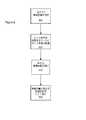
図1(Figure7)は、センサの代替実施例を示す。ここで、Figure1のパッド70A−Cは、ベゼル710を通って延びて導体730A−Cにより遠隔固定コンデンサ720A−Cに電気的に接続される微小センサ700A−Cで置換される。微小センサ700A−Cは一実施例では金属であるが、他実施例では他のタイプの低インピーダンス導電材料であってよい。この実施例では、遠隔固定コンデンサ内の絶縁誘電材料により与えられるESD遮へいを維持しながら静電容量型センシング構造を全体的に小さくできる。この実施例の微小センサは、皮膚と電気的に接触する必要がない。その代わりに、少なくともいくつかの実施例において、センサ上の酸化物層等の偶発的な膜又は死んだ若しくは脱水状態の皮膚の層が皮膚からセンサを完全に又は部分的に絶縁する。皮膚とセンサとの間で十分に低い抵抗の接触が図れない場合であっても、センサと皮膚との間の相対的に薄い偶発的な膜に起因して皮膚とセンサとの間には有効に大きな静電容量が存在する。この大きな静電容量は当該相対的に小さな遠隔コンデンサと直列になる。このため、このセンサ静電容量が遠隔静電容量の測定に影響を与えることがない。この構成の付加的な特徴は、センサ700A−Cへの皮膚の近接を検知する所望の感度を与えるべく遠隔コンデンサ720A−Cの誘電率を調整できることである。Figure7から理解できるように、Figure7に示される残りの機能は、機能レベルにおいてFigure6の機能と実質的に同じである。このため、同じ要素には同じ参照番号を付す。ベゼル表面からある程度遠隔した場所にコンデンサ720A−Cを配置できることにより、増大した感度を与え得る大きなコンデンサを使用することができる。この構成はまた、静電放電に対する保護設計を可能とする。コンデンサを遠隔配置することにより、端子間に十分な距離を有するコンデンサを使用して一端子と他端子とのアーク放電を回避することができるからである。 FIG. 1 (Figure 7) shows an alternative embodiment of the sensor. Here, FIG. 1 pads 70A-C are replaced with
いくつかの実施例では、センサのキャリブレーションを行うことが望ましい。センサの感度は装置ごとにある程度異なり得るからである。このキャリブレーションは、図2(Figure8)に示されるように製造中に実施することができる。ステップ800では、開放空気中の基準静電容量が測定される。次に、既知かつ反復可能な特性でヒトの皮膚を複製するツールを使用して、810においてセンサが当該ツールに対して配置される。これにより、静電容量の変化が得られ、820において測定される。開放空気と皮膚への直接接触との間の静電容量の変化により、その後830に示されるように、当該特定のセンサの特性を確立するべく用いられる範囲が得られる。 In some embodiments, it may be desirable to calibrate the sensor. This is because the sensitivity of the sensor can vary from device to device to some extent. This calibration can be performed during manufacture as shown in FIG. 2 (FIGURE 8). In
なお、当業者であれば、本発明から逸脱することなく多数の代替例及び均等例を実施することができる。いくつかの例では、様々なセンサの幾何形状を使用することができる。センサの数、センサの有効サイズ、装置のアクティブな皮膚接触表面から凹んだセンサまでの距離、及び他の同様な構成を変更することが含まれる。本発明の一実施例では、図面に示されるように、各センサ70のアクティブ領域は5.08mm×3.81mm(0.200”×0.150”)[寸法]の微小さである。 One skilled in the art can implement numerous alternatives and equivalents without departing from the present invention. In some examples, various sensor geometries may be used. It includes changing the number of sensors, the effective size of the sensor, the distance from the active skin contact surface of the device to the recessed sensor, and other similar configurations. In one embodiment of the present invention, as shown in the drawings, the active area of each sensor 70 is as small as 5.08 mm × 3.81 mm (0.200 ″ × 0.150 ″) [dimensions].
同様に、他のタイプのセンサ回路が使用できる。センサ出力は、純粋にハードウェア的に処理されてよい。または、装置は、様々な異なるソフトウェア及び/又はハードウェアアルゴリズムを用いて、例えば4つのボタンのうち3つが接触を示した場合に使用を許可するというように安全性、信頼性、又は有効特性を変化させてよい。加えて、回路は、センサからの信号を様々な付加的な目的のために比較することができる。例えば、接触表面を通しての熱流束を評価することができる。 Similarly, other types of sensor circuits can be used. The sensor output may be processed purely in hardware. Alternatively, the device may use various different software and / or hardware algorithms to provide safety, reliability, or effective characteristics, such as allowing use when three of the four buttons indicate contact. You can change it. In addition, the circuit can compare the signals from the sensors for various additional purposes. For example, the heat flux through the contact surface can be evaluated.
したがって、本発明の例示的図面及び詳細な実施例が説明及び図示されたが、本発明の範囲は説明に係る特定の実施例に限定されない。図示及び説明に係る実施例は、限定ではなく例示としてみなされる。本発明は添付の特許請求の範囲によってのみ限定される。 Thus, although exemplary drawings and detailed embodiments of the invention have been described and illustrated, the scope of the invention is not limited to the specific embodiments described. The embodiments shown and described are to be regarded as illustrative and not restrictive. The present invention is limited only by the appended claims.
加えて、上述された本明細書の好ましい実施例により実施できる方法では、動作が、選択された順序で説明されている。しかし、当該順序は選択されたものであるから、もっぱら明確性及び便宜性のために並べられたものであって、請求項に明示され又は当業者が必要と理解する場合を除いては当該動作を実施するべく任意の特定順序が要求されることを示唆するものではない。 In addition, in the methods that can be performed according to the preferred embodiments described herein above, the operations are described in a selected order. However, since the order is selected, it is arranged only for clarity and convenience, and it is not specifically stated in the claims or unless otherwise understood by those skilled in the art. It does not imply that any particular order is required to implement.
Claims (20)
Translated fromJapanese前記光源からの光を発する窓と、
前記窓を取り囲み前記窓と実質的に共通平面のベゼルと、
前記窓の周縁かつ前記ベゼルの下に配置された複数の静電容量型センサと
を含み、
前記静電容量型センサは、前記ベゼルと実質的に接触する皮膚の存在を検知することにより、前記静電容量型センサの少なくとも所定数が前記皮膚の存在を検知した場合にのみ前記光源が発光する皮膚科治療装置。A light source;
A window emitting light from the light source;
A bezel that surrounds the window and is substantially coplanar with the window;
A plurality of capacitive sensors disposed at the periphery of the window and under the bezel;
The capacitive sensor detects the presence of skin substantially in contact with the bezel, so that the light source emits light only when at least a predetermined number of the capacitive sensors detect the presence of the skin. Dermatological treatment device.
前記光源からの光を発する窓と、
前記窓を取り囲むベゼルと、
前記窓の周縁に配置されて前記ベゼルを通して延びる複数の接触部と、
複数の静電容量部と、
コントローラと
を含み、
前記静電容量部の1つが各接触部に電気的に接続され、
前記コントローラは、関連する前記接触部での皮膚の存在によりもたらされる前記静電容量部の少なくともいくつかの値の認識された変化に応答し、
前記光源は、前記皮膚の存在が前記コントローラにより検知された場合にのみ発光する皮膚科治療装置。A light source having an output;
A window emitting light from the light source;
A bezel surrounding the window;
A plurality of contacts disposed at a periphery of the window and extending through the bezel;
A plurality of capacitance units;
Including the controller and
One of the capacitance portions is electrically connected to each contact portion;
The controller is responsive to a perceived change in at least some values of the capacitive portion caused by the presence of skin at the associated contact portion;
The light source is a dermatological treatment device that emits light only when the presence of the skin is detected by the controller.
前記表面に配置された複数の導電接触部と、
それぞれが前記複数の接触部の少なくとも1つに電気的に接続された複数の静電容量部と、
前記静電容量部に接続されて前記静電容量部での少なくともいくつかの変化に応答するコントローラと
を含み、
前記接触部が皮膚に近接すると前記静電容量部に変化が生じ、
前記コントローラは、前記皮膚が関連する前記接触部に近接して存在することを示す出力信号を生成する前記静電容量の変化皮膚検知装置。A non-conductive surface;
A plurality of conductive contacts disposed on the surface;
A plurality of capacitance portions each electrically connected to at least one of the plurality of contact portions;
A controller connected to the capacitance unit and responsive to at least some changes in the capacitance unit;
When the contact portion is close to the skin, a change occurs in the capacitance portion,
The capacitance change skin sensing device, wherein the controller generates an output signal indicating that the skin is in proximity to the associated contact.
Applications Claiming Priority (2)
| Application Number | Priority Date | Filing Date | Title |
|---|---|---|---|
| US95468207P | 2007-08-08 | 2007-08-08 | |
| US60/954,682 | 2007-08-08 |
Related Parent Applications (1)
| Application Number | Title | Priority Date | Filing Date |
|---|---|---|---|
| JP2010520342ADivisionJP5595270B2 (en) | 2007-08-08 | 2008-08-08 | Capacitive sensing method and apparatus for skin detection |
Publications (1)
| Publication Number | Publication Date |
|---|---|
| JP2014237025Atrue JP2014237025A (en) | 2014-12-18 |
Family
ID=40341785
Family Applications (2)
| Application Number | Title | Priority Date | Filing Date |
|---|---|---|---|
| JP2010520342AExpired - Fee RelatedJP5595270B2 (en) | 2007-08-08 | 2008-08-08 | Capacitive sensing method and apparatus for skin detection |
| JP2014159520APendingJP2014237025A (en) | 2007-08-08 | 2014-08-05 | Capacitive sensing method and device for detecting skin |
Family Applications Before (1)
| Application Number | Title | Priority Date | Filing Date |
|---|---|---|---|
| JP2010520342AExpired - Fee RelatedJP5595270B2 (en) | 2007-08-08 | 2008-08-08 | Capacitive sensing method and apparatus for skin detection |
Country Status (4)
| Country | Link |
|---|---|
| US (1) | US8709003B2 (en) |
| EP (1) | EP2194899A4 (en) |
| JP (2) | JP5595270B2 (en) |
| WO (1) | WO2009021225A1 (en) |
Cited By (1)
| Publication number | Priority date | Publication date | Assignee | Title |
|---|---|---|---|---|
| KR101611231B1 (en)* | 2015-02-06 | 2016-04-11 | 김용호 | laser irradiation device for medical |
Families Citing this family (44)
| Publication number | Priority date | Publication date | Assignee | Title |
|---|---|---|---|---|
| US20060149343A1 (en)* | 1996-12-02 | 2006-07-06 | Palomar Medical Technologies, Inc. | Cooling system for a photocosmetic device |
| US6648904B2 (en)* | 2001-11-29 | 2003-11-18 | Palomar Medical Technologies, Inc. | Method and apparatus for controlling the temperature of a surface |
| WO2004000098A2 (en) | 2002-06-19 | 2003-12-31 | Palomar Medical Technologies, Inc. | Method and apparatus for treatment of cutaneous and subcutaneous conditions |
| EP2604216B1 (en) | 2003-02-25 | 2018-08-22 | Tria Beauty, Inc. | Self-contained, diode-laser-based dermatologic treatment apparatus |
| US20100069898A1 (en)* | 2003-02-25 | 2010-03-18 | Tria Beauty, Inc. | Acne Treatment Method, System and Device |
| US20060009749A1 (en)* | 2004-02-19 | 2006-01-12 | Weckwerth Mark V | Efficient diffuse light source assembly and method |
| US8777935B2 (en)* | 2004-02-25 | 2014-07-15 | Tria Beauty, Inc. | Optical sensor and method for identifying the presence of skin |
| US7856985B2 (en) | 2005-04-22 | 2010-12-28 | Cynosure, Inc. | Method of treatment body tissue using a non-uniform laser beam |
| US7586957B2 (en) | 2006-08-02 | 2009-09-08 | Cynosure, Inc | Picosecond laser apparatus and methods for its operation and use |
| US20080262484A1 (en)* | 2007-04-23 | 2008-10-23 | Nlight Photonics Corporation | Motion-controlled laser surface treatment apparatus |
| WO2009132355A1 (en)* | 2008-04-25 | 2009-10-29 | Tria Beauty, Inc. | Optical sensor and method for identifying the presence of skin and the pigmentation of skin |
| KR101740350B1 (en) | 2009-10-16 | 2017-05-26 | 셰이서 인코포레이티드 | Power supply for light-based dermatologic treatment device |
| US8518027B2 (en)* | 2009-10-28 | 2013-08-27 | Tria Beauty, Inc. | Phototherapy device thermal control apparatus and method |
| US9302118B2 (en) | 2009-10-28 | 2016-04-05 | Tria Beauty, Inc. | Phototherapy device thermal control apparatus and method |
| FR2954690A1 (en)* | 2009-12-29 | 2011-07-01 | Ekkyo | DEVICE FOR DERMATOLOGICAL TREATMENT BY LIGHT BEAM |
| IT1404140B1 (en)* | 2010-11-26 | 2013-11-15 | Touch Life Rehab S R L | SYSTEM AND METHOD OF PROTECTION FOR THE USE OF A LASER |
| US20120277659A1 (en)* | 2011-04-29 | 2012-11-01 | Palomar Medical Technologies, Inc. | Sensor-lotion system for use with body treatment devices |
| US8968281B2 (en)* | 2011-07-28 | 2015-03-03 | Illuminage Beauty, Ltd. | Handholdable laser device featuring sensor for eye safe activation |
| AT512238A1 (en)* | 2011-11-16 | 2013-06-15 | Pantec Biosolutions Ag | SKIN CONTACT DETECTION DEVICE |
| GB2496895A (en)* | 2011-11-25 | 2013-05-29 | Cyden Ltd | Skin treatment apparatus |
| EP2839552A4 (en) | 2012-04-18 | 2015-12-30 | Cynosure Inc | PICOSECOND LASER APPARATUS AND METHOD OF PROCESSING TARGET TISSUES USING THE SAME |
| WO2014068414A1 (en) | 2012-10-31 | 2014-05-08 | Koninklijke Philips N.V. | Skin treatment device having a skin detector |
| US10285757B2 (en) | 2013-03-15 | 2019-05-14 | Cynosure, Llc | Picosecond optical radiation systems and methods of use |
| GB2526764B (en) | 2013-12-04 | 2020-10-07 | Ipulse Ltd | Skin treatment apparatus utilising intense pulsed light (IPL) |
| WO2015106118A1 (en) | 2014-01-09 | 2015-07-16 | Sonitec Llc | Systems and methods using ultrasound for treatment |
| FR3018694B1 (en)* | 2014-03-24 | 2020-01-03 | Lucibel Sa | PHOTOTHERAPY TREATMENT DEVICE |
| KR101426539B1 (en) | 2014-04-22 | 2014-08-13 | (주)하배런메디엔뷰티 | Hair removing apparatus |
| EP3069762B1 (en)* | 2015-03-20 | 2018-08-08 | Capillus LLC | Laser therapy apparatus |
| US10099065B2 (en) | 2015-03-20 | 2018-10-16 | Capillus, Llc | Laser therapy apparatus and method |
| DE102015121409A1 (en)* | 2015-12-09 | 2017-06-14 | Emperra Gmbh E-Health Technologies | Injection device for injecting metered quantities of a liquid therapeutic agent |
| CN108885134A (en) | 2016-02-08 | 2018-11-23 | 平等化妆品公司 | Apparatus and methods for formulating and dispensing visually customized cosmetics |
| EP3641883B1 (en)* | 2017-06-20 | 2021-10-13 | Colgate-Palmolive Company | Skin care implement and system |
| JP3227542U (en) | 2017-07-25 | 2020-09-03 | ブリー.エルエルシー | Systems and devices for cosmetic customization |
| WO2019071315A1 (en)* | 2017-10-12 | 2019-04-18 | Somark Group Limited | Systems and methods for marking or penetrating a part of an animal |
| WO2019165426A1 (en) | 2018-02-26 | 2019-08-29 | Cynosure, Inc. | Q-switched cavity dumped sub-nanosecond laser |
| CN108186113A (en)* | 2018-03-28 | 2018-06-22 | 深圳可思美科技有限公司 | Skin identifies electro-optical device, method and depilatory apparatus |
| US10575623B2 (en) | 2018-06-29 | 2020-03-03 | Sephora USA, Inc. | Color capture system and device |
| US12233280B2 (en)* | 2018-07-26 | 2025-02-25 | Azulite, Inc. | Adhesive phototherapy method, system, and devices for acne |
| US10967197B2 (en) | 2018-08-29 | 2021-04-06 | Azulite, Inc. | Phototherapy devices and methods for treating truncal acne and scars |
| US20220212026A1 (en)* | 2020-02-29 | 2022-07-07 | Cutera, Inc. | Dermatological laser systems and methods with pressure sensing handpiece |
| US11253720B2 (en) | 2020-02-29 | 2022-02-22 | Cutera, Inc. | Dermatological systems and methods with handpiece for coaxial pulse delivery and temperature sensing |
| CN113827183B (en)* | 2020-06-23 | 2023-11-14 | 福州数据技术研究院有限公司 | Device and method for photo-acoustic probe light-emitting protection based on transparent capacitance film |
| US12070729B2 (en) | 2020-08-19 | 2024-08-27 | Blee. Llc | System and device for customization of cosmetics |
| WO2025140336A1 (en)* | 2023-12-26 | 2025-07-03 | Shenzhen Ulike Smart Electronics Co., Ltd. | Method for manufacturing circuit board, and light-based skin treatment device |
Citations (6)
| Publication number | Priority date | Publication date | Assignee | Title |
|---|---|---|---|---|
| JP2004533866A (en)* | 2000-11-16 | 2004-11-11 | イノテック ユーエスエイ インコーポレイテッド | Laser skin perforator |
| JP2005278724A (en)* | 2004-03-26 | 2005-10-13 | Ya Man Ltd | Treatment apparatus |
| JP2006192073A (en)* | 2005-01-13 | 2006-07-27 | Matsushita Electric Ind Co Ltd | Phototherapy device |
| US20060206103A1 (en)* | 2001-03-02 | 2006-09-14 | Palomar Medical Technologies, Inc. | Dermatological treatment device |
| JP2006525036A (en)* | 2003-03-06 | 2006-11-09 | スペクトラジェニクス インコーポレイテッド | Skin contact sensing method and apparatus |
| US20070038206A1 (en)* | 2004-12-09 | 2007-02-15 | Palomar Medical Technologies, Inc. | Photocosmetic device |
Family Cites Families (192)
| Publication number | Priority date | Publication date | Assignee | Title |
|---|---|---|---|---|
| US3307533A (en)* | 1963-11-26 | 1967-03-07 | Meredith | Apparatus for generating and controlling pressure |
| US3538919A (en) | 1967-04-07 | 1970-11-10 | Gregory System Inc | Depilation by means of laser energy |
| US3622743A (en) | 1969-04-28 | 1971-11-23 | Hrand M Muncheryan | Laser eraser and microwelder |
| US3693623A (en) | 1970-12-25 | 1972-09-26 | Gregory System Inc | Photocoagulation means and method for depilation |
| US3834391A (en) | 1973-01-19 | 1974-09-10 | Block Carol Ltd | Method and apparatus for photoepilation |
| US3821510A (en)* | 1973-02-22 | 1974-06-28 | H Muncheryan | Hand held laser instrumentation device |
| FR2390968A1 (en) | 1977-05-16 | 1978-12-15 | Skovajsa Joseph | Local acupuncture treatment appts. - has oblong head with end aperture and contains laser diode unit (NL 20.11.78) |
| JPS5824124B2 (en) | 1978-10-05 | 1983-05-19 | 松下電器産業株式会社 | hair adjustment tool |
| US4240738A (en) | 1979-06-14 | 1980-12-23 | Vivitar Corporation | Light mixing system for a photographic enlarger |
| US4388924A (en)* | 1981-05-21 | 1983-06-21 | Weissman Howard R | Method for laser depilation |
| US4573466A (en)* | 1981-05-29 | 1986-03-04 | Hitachi, Ltd. | Surgical equipment |
| US4423736A (en)* | 1981-10-13 | 1984-01-03 | Purdue Research Foundation | Method for evaluation of erythema utilizing skin reflectance measurements |
| GB2123287B (en) | 1982-07-09 | 1986-03-05 | Anna Gunilla Sutton | Depilaton device |
| US4551628A (en) | 1983-04-01 | 1985-11-05 | Mcdonnell Douglas Corporation | Radiation dispersing cavities |
| US4608978A (en) | 1983-09-26 | 1986-09-02 | Carol Block Limited | Method and apparatus for photoepiltion |
| US4592353A (en)* | 1984-05-22 | 1986-06-03 | Surgical Laser Technologies Ohio, Inc. | Medical and surgical laser probe |
| IL75998A0 (en)* | 1984-08-07 | 1985-12-31 | Medical Laser Research & Dev C | Laser system for providing target tissue specific energy deposition |
| DE3577026D1 (en)* | 1984-10-25 | 1990-05-10 | Candela Laser Corp | TUNABLE LONG-PULSE DYE LASER. |
| FR2579884B1 (en)* | 1985-04-09 | 1988-12-02 | Sanofi Sa | |
| US4690141A (en) | 1985-09-16 | 1987-09-01 | Castel John C | Fresnel lens light applicator |
| WO1988000072A1 (en)* | 1986-06-30 | 1988-01-14 | Medical Laser Research Co., Ltd. | Semiconductor laser therapeutic apparatus |
| US5259380A (en) | 1987-11-04 | 1993-11-09 | Amcor Electronics, Ltd. | Light therapy system |
| US4930504A (en)* | 1987-11-13 | 1990-06-05 | Diamantopoulos Costas A | Device for biostimulation of tissue and method for treatment of tissue |
| US5059013A (en) | 1988-08-29 | 1991-10-22 | Kantilal Jain | Illumination system to produce self-luminous light beam of selected cross-section, uniform intensity and selected numerical aperture |
| US5057104A (en)* | 1989-05-30 | 1991-10-15 | Cyrus Chess | Method and apparatus for treating cutaneous vascular lesions |
| US5486172A (en)* | 1989-05-30 | 1996-01-23 | Chess; Cyrus | Apparatus for treating cutaneous vascular lesions |
| US5846252A (en) | 1989-12-21 | 1998-12-08 | Mehl, Sr.; Thomas L. | Method of removing hair from the body and inhibiting future growth |
| US5109465A (en)* | 1990-01-16 | 1992-04-28 | Summit Technology, Inc. | Beam homogenizer |
| US5059192A (en) | 1990-04-24 | 1991-10-22 | Nardo Zaias | Method of hair depilation |
| FR2665366A1 (en) | 1990-07-10 | 1992-02-07 | Rameil Jean | Apparatus for dermal electrostimulation |
| US5075971A (en) | 1990-07-17 | 1991-12-31 | Wahl Clipper Corporation | Methods and apparatus for trimming hair and disposing of hair clippings |
| DE4032860A1 (en) | 1990-10-12 | 1992-04-16 | Zeiss Carl Fa | POWER-CONTROLLED CONTACT APPLICATOR FOR LASER RADIATION |
| US5549660A (en) | 1990-11-15 | 1996-08-27 | Amron, Ltd. | Method of treating acne |
| US6390370B1 (en) | 1990-11-15 | 2002-05-21 | Symbol Technologies, Inc. | Light beam scanning pen, scan module for the device and method of utilization |
| DE9116216U1 (en)* | 1990-12-19 | 1992-05-27 | Dornier MedizinLaser GmbH, 82110 Germering | Application device for laser radiation |
| IL97531A (en)* | 1991-03-12 | 1995-12-31 | Kelman Elliot | Hair cutting apparatus |
| EP0792663B1 (en) | 1991-04-05 | 2001-11-21 | Indigo Medical, Incorporated | Apparatus using a laser lucent needle |
| US5769844A (en)* | 1991-06-26 | 1998-06-23 | Ghaffari; Shahriar | Conventional light-pumped high power system for medical applications |
| US5871480A (en)* | 1991-10-29 | 1999-02-16 | Thermolase Corporation | Hair removal using photosensitizer and laser |
| US5425728A (en)* | 1991-10-29 | 1995-06-20 | Tankovich; Nicolai I. | Hair removal device and method |
| US5752949A (en)* | 1991-10-29 | 1998-05-19 | Thermolase Corporation | Hair removal method |
| US5817089A (en) | 1991-10-29 | 1998-10-06 | Thermolase Corporation | Skin treatment process using laser |
| US5752948A (en)* | 1991-10-29 | 1998-05-19 | Thermolase Corporation | Hair removal method |
| US5226907A (en)* | 1991-10-29 | 1993-07-13 | Tankovich Nikolai I | Hair removal device and method |
| US5344418A (en) | 1991-12-12 | 1994-09-06 | Shahriar Ghaffari | Optical system for treatment of vascular lesions |
| US5342404A (en) | 1992-04-03 | 1994-08-30 | Intermedics, Inc. | Implantable medical interventional device |
| US5405368A (en)* | 1992-10-20 | 1995-04-11 | Esc Inc. | Method and apparatus for therapeutic electromagnetic treatment |
| US5295052A (en) | 1992-10-09 | 1994-03-15 | Luxtec Corporation | Light source assembly |
| US5683380A (en) | 1995-03-29 | 1997-11-04 | Esc Medical Systems Ltd. | Method and apparatus for depilation using pulsed electromagnetic radiation |
| US6280438B1 (en) | 1992-10-20 | 2001-08-28 | Esc Medical Systems Ltd. | Method and apparatus for electromagnetic treatment of the skin, including hair depilation |
| US5643252A (en)* | 1992-10-28 | 1997-07-01 | Venisect, Inc. | Laser perforator |
| US5707403A (en)* | 1993-02-24 | 1998-01-13 | Star Medical Technologies, Inc. | Method for the laser treatment of subsurface blood vessels |
| US5647866A (en)* | 1993-11-09 | 1997-07-15 | Zaias; Nardo | Method of hair depilation |
| US6277111B1 (en) | 1993-12-08 | 2001-08-21 | Icn Photonics Limited | Depilation |
| US5628744A (en)* | 1993-12-21 | 1997-05-13 | Laserscope | Treatment beam handpiece |
| US5591127A (en) | 1994-01-28 | 1997-01-07 | Barwick, Jr.; Billie J. | Phacoemulsification method and apparatus |
| US5556612A (en) | 1994-03-15 | 1996-09-17 | The General Hospital Corporation | Methods for phototherapeutic treatment of proliferative skin diseases |
| US5464436A (en) | 1994-04-28 | 1995-11-07 | Lasermedics, Inc. | Method of performing laser therapy |
| US5519534A (en)* | 1994-05-25 | 1996-05-21 | The Government Of The United States Of America As Represented By The Secretary Of The Department Of Health And Human Services | Irradiance attachment for an optical fiber to provide a uniform level of illumination across a plane |
| US5473408A (en) | 1994-07-01 | 1995-12-05 | Anvik Corporation | High-efficiency, energy-recycling exposure system |
| US5431647A (en)* | 1994-07-13 | 1995-07-11 | Pioneer Optics Company | Fiberoptic cylindrical diffuser |
| US5669916A (en) | 1994-09-28 | 1997-09-23 | The General Hospital Corporation | Method of hair removal |
| ATE205723T1 (en) | 1994-11-04 | 2001-10-15 | Polymun Scient Immunbio Forsch | APPLICATION OF SOD IN LIPOSOMES |
| US5632741A (en)* | 1995-01-20 | 1997-05-27 | Lucid Technologies, Inc. | Epilation system |
| US5735844A (en)* | 1995-02-01 | 1998-04-07 | The General Hospital Corporation | Hair removal using optical pulses |
| US5595568A (en)* | 1995-02-01 | 1997-01-21 | The General Hospital Corporation | Permanent hair removal using optical pulses |
| US5728090A (en)* | 1995-02-09 | 1998-03-17 | Quantum Devices, Inc. | Apparatus for irradiating living cells |
| US5885273A (en)* | 1995-03-29 | 1999-03-23 | Esc Medical Systems, Ltd. | Method for depilation using pulsed electromagnetic radiation |
| US5624435A (en)* | 1995-06-05 | 1997-04-29 | Cynosure, Inc. | Ultra-long flashlamp-excited pulse dye laser for therapy and method therefor |
| US5658323A (en) | 1995-07-12 | 1997-08-19 | Miller; Iain D. | Method and apparatus for dermatology treatment |
| JP3551996B2 (en) | 1995-08-25 | 2004-08-11 | 松下電器産業株式会社 | Medical laser probe |
| US5849029A (en) | 1995-12-26 | 1998-12-15 | Esc Medical Systems, Ltd. | Method for controlling the thermal profile of the skin |
| US5824023A (en) | 1995-10-12 | 1998-10-20 | The General Hospital Corporation | Radiation-delivery device |
| IL118229A0 (en)* | 1996-05-12 | 1997-03-18 | Laser Ind Ltd | Apparatus and method for cutaneous treatment employing a laser |
| US5879346A (en)* | 1995-12-18 | 1999-03-09 | Esc Medical Systems, Ltd. | Hair removal by selective photothermolysis with an alexandrite laser |
| US6350276B1 (en)* | 1996-01-05 | 2002-02-26 | Thermage, Inc. | Tissue remodeling apparatus containing cooling fluid |
| US7022121B2 (en) | 1999-03-09 | 2006-04-04 | Thermage, Inc. | Handpiece for treatment of tissue |
| US6114862A (en)* | 1996-02-14 | 2000-09-05 | Stmicroelectronics, Inc. | Capacitive distance sensor |
| US5630811A (en)* | 1996-03-25 | 1997-05-20 | Miller; Iain D. | Method and apparatus for hair removal |
| US5871479A (en)* | 1996-11-07 | 1999-02-16 | Cynosure, Inc. | Alexandrite laser system for hair removal and method therefor |
| US5843072A (en) | 1996-11-07 | 1998-12-01 | Cynosure, Inc. | Method for treatment of unwanted veins and device therefor |
| CN1220591A (en) | 1996-04-09 | 1999-06-23 | 希诺索尔公司 | Alexandrite laser system for treatment of dermatological specimens |
| US5766214A (en)* | 1996-04-18 | 1998-06-16 | Mehl, Sr.; Thomas L. | Melanin enhanced photothermolysis hair removal |
| US5743901A (en)* | 1996-05-15 | 1998-04-28 | Star Medical Technologies, Inc. | High fluence diode laser device and method for the fabrication and use thereof |
| DE19629978A1 (en) | 1996-07-25 | 1998-01-29 | Heinz Renner | Cable-less laser pistol for firearms training |
| US6106514A (en) | 1996-08-12 | 2000-08-22 | O'donnell, Jr.; Francis E. | Laser method for subsurface cutaneous treatment |
| US6096029A (en) | 1997-02-24 | 2000-08-01 | Laser Skin Toner, Inc. | Laser method for subsurface cutaneous treatment |
| JP3036232U (en) | 1996-09-26 | 1997-04-15 | ヤーマン株式会社 | Optical hair removal device |
| IL119683A (en)* | 1996-11-25 | 2002-12-01 | Rachel Lubart | Method and device for light irradiation into tissue |
| JPH10153720A (en)* | 1996-11-25 | 1998-06-09 | Sony Corp | Optical transmitter and receiver |
| US6653618B2 (en)* | 2000-04-28 | 2003-11-25 | Palomar Medical Technologies, Inc. | Contact detecting method and apparatus for an optical radiation handpiece |
| US8182473B2 (en) | 1999-01-08 | 2012-05-22 | Palomar Medical Technologies | Cooling system for a photocosmetic device |
| US6517532B1 (en) | 1997-05-15 | 2003-02-11 | Palomar Medical Technologies, Inc. | Light energy delivery head |
| US6015404A (en)* | 1996-12-02 | 2000-01-18 | Palomar Medical Technologies, Inc. | Laser dermatology with feedback control |
| US7204832B2 (en)* | 1996-12-02 | 2007-04-17 | Pálomar Medical Technologies, Inc. | Cooling system for a photo cosmetic device |
| US6063108A (en) | 1997-01-06 | 2000-05-16 | Salansky; Norman | Method and apparatus for localized low energy photon therapy (LEPT) |
| US5810801A (en) | 1997-02-05 | 1998-09-22 | Candela Corporation | Method and apparatus for treating wrinkles in skin using radiation |
| WO1998037811A1 (en)* | 1997-02-28 | 1998-09-03 | Electro-Optical Sciences, Inc. | Systems and methods for the multispectral imaging and characterization of skin tissue |
| US5966210A (en) | 1997-03-20 | 1999-10-12 | Hartford Hospital | Apparatus for evaluating the performance characteristics of endoscopes |
| US6441943B1 (en) | 1997-04-02 | 2002-08-27 | Gentex Corporation | Indicators and illuminators using a semiconductor radiation emitter package |
| ES2226133T3 (en) | 1997-05-15 | 2005-03-16 | Palomar Medical Technologies, Inc. | DERMATOLOGICAL TREATMENT DEVICE. |
| CA2206203A1 (en) | 1997-05-27 | 1998-11-27 | University Of British Columbia | Photoactivation of endogenous porphyrins for treatment of psoriasis |
| US6099520A (en) | 1997-06-10 | 2000-08-08 | Shimoji; Yutaka | Method of using a cordless medical laser to cure composites and sterilize living tissue |
| EP1018955A4 (en) | 1997-06-24 | 2001-06-20 | Laser Aesthetics Inc | Pulsed filament lamp for dermatological treatment |
| US6273885B1 (en) | 1997-08-16 | 2001-08-14 | Cooltouch Corporation | Handheld photoepilation device and method |
| US6251127B1 (en)* | 1997-08-25 | 2001-06-26 | Advanced Photodynamic Technologies, Inc. | Dye treatment solution and photodynamic therapy and method of using same |
| US20030133292A1 (en)* | 1999-11-18 | 2003-07-17 | Mueller George G. | Methods and apparatus for generating and modulating white light illumination conditions |
| ATE328642T1 (en) | 1997-10-08 | 2006-06-15 | Gen Hospital Corp | PHOTOTHERAPEUTIC SYSTEMS |
| US6165170A (en) | 1998-01-29 | 2000-12-26 | International Business Machines Corporation | Laser dermablator and dermablation |
| US6080146A (en)* | 1998-02-24 | 2000-06-27 | Altshuler; Gregory | Method and apparatus for hair removal |
| US6059765A (en)* | 1998-02-26 | 2000-05-09 | Allergan Sales, Inc. | Fluid management system with vertex chamber |
| ES2245506T3 (en)* | 1998-03-12 | 2006-01-01 | Palomar Medical Technologies, Inc. | ELECTROMAGNETIC RADIATION APPLICATION SYSTEM ON SKIN. |
| CA2326120C (en) | 1998-03-27 | 2015-01-13 | The General Hospital Corporation | Method and apparatus for the selective targeting of lipid-rich tissues |
| US6516013B1 (en)* | 1999-12-20 | 2003-02-04 | Lambda Physik Ag | Laser beam monitoring apparatus and method |
| WO2000002491A1 (en) | 1998-07-09 | 2000-01-20 | Curelight Ltd. | Apparatus and method for efficient high energy photodynamic therapy of acne vulgaris and seborrhea |
| US6322584B2 (en) | 1998-07-31 | 2001-11-27 | Surx, Inc. | Temperature sensing devices and methods to shrink tissues |
| US6138041A (en) | 1998-09-23 | 2000-10-24 | Ccm Cellular Connection Of Miami, Inc. | Device for safe use of a portable cellular telephone while driving |
| US6478990B1 (en)* | 1998-09-25 | 2002-11-12 | Q2100, Inc. | Plastic lens systems and methods |
| US6228074B1 (en)* | 1998-10-15 | 2001-05-08 | Stephen Almeida | Multiple pulse photo-epilator |
| US6160831A (en) | 1998-10-26 | 2000-12-12 | Lambda Physik Gmbh | Wavelength calibration tool for narrow band excimer lasers |
| US6663659B2 (en)* | 2000-01-13 | 2003-12-16 | Mcdaniel David H. | Method and apparatus for the photomodulation of living cells |
| US6887260B1 (en)* | 1998-11-30 | 2005-05-03 | Light Bioscience, Llc | Method and apparatus for acne treatment |
| US6183500B1 (en)* | 1998-12-03 | 2001-02-06 | Sli Lichtsysteme Gmbh | Process and apparatus for the cosmetic treatment of acne vulgaris |
| US6514242B1 (en)* | 1998-12-03 | 2003-02-04 | David Vasily | Method and apparatus for laser removal of hair |
| US6183773B1 (en) | 1999-01-04 | 2001-02-06 | The General Hospital Corporation | Targeting of sebaceous follicles as a treatment of sebaceous gland disorders |
| US6243406B1 (en) | 1999-03-12 | 2001-06-05 | Peter Heist | Gas performance control system for gas discharge lasers |
| US6383176B1 (en) | 1999-03-15 | 2002-05-07 | Altus Medical, Inc. | Hair removal device and method |
| US6419873B1 (en) | 1999-03-19 | 2002-07-16 | Q2100, Inc. | Plastic lens systems, compositions, and methods |
| DE19915000C2 (en)* | 1999-04-01 | 2002-05-08 | Microlas Lasersystem Gmbh | Device and method for controlling the intensity distribution of a laser beam |
| US6778574B1 (en) | 1999-04-05 | 2004-08-17 | Sharp Kabushiki Kaisha | Semiconductor laser device and its manufacturing method, and optical communication system and optical sensor system |
| JP2000300683A (en) | 1999-04-20 | 2000-10-31 | Shimoji Yutaka | Dental and medical cordless lasers and methods for curing composites and sterilizing living tissue using the same |
| US6533775B1 (en)* | 1999-05-05 | 2003-03-18 | Ioana M. Rizoiu | Light-activated hair treatment and removal device |
| US20020128695A1 (en) | 1999-07-07 | 2002-09-12 | Yoram Harth | Apparatus and method for high energy photodynamic therapy of acne vulgaris and seborrhea |
| US20040122492A1 (en)* | 1999-07-07 | 2004-06-24 | Yoram Harth | Phototherapeutic treatment of skin conditions |
| US20020173833A1 (en) | 1999-07-07 | 2002-11-21 | Avner Korman | Apparatus and method for high energy photodynamic therapy of acne vulgaris, seborrhea and other skin disorders |
| US20030216795A1 (en) | 1999-07-07 | 2003-11-20 | Yoram Harth | Apparatus and method for high energy photodynamic therapy of acne vulgaris, seborrhea and other skin disorders |
| US6290713B1 (en) | 1999-08-24 | 2001-09-18 | Thomas A. Russell | Flexible illuminators for phototherapy |
| US6406474B1 (en) | 1999-09-30 | 2002-06-18 | Ceramoptec Ind Inc | Device and method for application of radiation |
| JP4495894B2 (en)* | 2000-01-25 | 2010-07-07 | パロマー・メディカル・テクノロジーズ・インコーポレーテッド | Device for medical treatment using long-term electromagnetic radiation |
| US20020097587A1 (en)* | 2000-02-11 | 2002-07-25 | Krietzman Mark Howard | Variable output laser illuminator and targeting device |
| JP2001252363A (en)* | 2000-03-09 | 2001-09-18 | Ya Man Ltd | Laser beam radiating probe |
| TWI240788B (en) | 2000-05-04 | 2005-10-01 | Koninkl Philips Electronics Nv | Illumination system, light mixing chamber and display device |
| US6862307B2 (en)* | 2000-05-15 | 2005-03-01 | Lambda Physik Ag | Electrical excitation circuit for a pulsed gas laser |
| US6655810B2 (en) | 2000-06-21 | 2003-12-02 | Fujitsu Display Technologies Corporation | Lighting unit |
| US20020031160A1 (en)* | 2000-08-04 | 2002-03-14 | Lambda Physik Ag | Delay compensation for magnetic compressors |
| DE10044662A1 (en) | 2000-09-09 | 2002-03-21 | Cognis Deutschland Gmbh | Cosmetic or pharmaceutical composition e.g. useful for skin cleansing or acne treatment, comprise salicylic acid, alkyl and/or alkenyl oligoglycosides and alkyl ether sulfates |
| WO2002031467A1 (en)* | 2000-10-12 | 2002-04-18 | Amnis Corporation | Multipass cavity for illumination and excitation of moving objects |
| AU2002245163A1 (en) | 2000-10-20 | 2002-07-24 | Photomedex | Controlled dose delivery of ultraviolet light for treating skin disorders |
| EP1700573A3 (en) | 2000-12-28 | 2010-12-01 | Palomar Medical Technologies, Inc. | Apparatus for therapeutic EMR treatment of the skin |
| WO2002069825A2 (en) | 2001-03-02 | 2002-09-12 | Palomar Medical Technologies, Inc. | Apparatus and method for photocosmetic and photodermatological treatment |
| DE10123926A1 (en)* | 2001-03-08 | 2002-09-19 | Optomed Optomedical Systems Gmbh | irradiation device |
| US20020138071A1 (en) | 2001-03-22 | 2002-09-26 | Angeley David G. | Scanning laser handpiece with shaped output beam |
| US6941675B2 (en)* | 2001-04-02 | 2005-09-13 | Fred M. Slingo | Hair dryer employing far infrared radiation and negative ions |
| EP2314246A1 (en)* | 2001-05-23 | 2011-04-27 | Palomar Medical Technologies, Inc. | Cooling system for a photocosmetic device |
| US7217266B2 (en)* | 2001-05-30 | 2007-05-15 | Anderson R Rox | Apparatus and method for laser treatment with spectroscopic feedback |
| WO2002096366A2 (en)* | 2001-05-31 | 2002-12-05 | Miravant Pharmaceuticals, Inc. | Metallotetrapyrrolic photosensitizing agents for use in photodynamic therapy |
| US6723090B2 (en)* | 2001-07-02 | 2004-04-20 | Palomar Medical Technologies, Inc. | Fiber laser device for medical/cosmetic procedures |
| FR2826856B1 (en)* | 2001-07-09 | 2004-03-12 | Oreal | DEVICE FOR DETERMINING THE DEGREE OF A BODY TYPOLOGY CHARACTERISTIC |
| US20030009158A1 (en)* | 2001-07-09 | 2003-01-09 | Perricone Nicholas V. | Skin treatments using blue and violet light |
| JP4035418B2 (en) | 2001-10-31 | 2008-01-23 | 株式会社本田電子技研 | Proximity switch and object detection device |
| US6922523B2 (en)* | 2001-11-08 | 2005-07-26 | Johnson & Johnson Consumer Companies, Inc. | Method of promoting skin care products |
| US6648904B2 (en) | 2001-11-29 | 2003-11-18 | Palomar Medical Technologies, Inc. | Method and apparatus for controlling the temperature of a surface |
| EP1455671B1 (en) | 2001-12-10 | 2007-06-13 | Inolase 2002 Ltd. | Method and apparatus for improving safety during exposure to a monochromatic light source |
| US7540869B2 (en)* | 2001-12-27 | 2009-06-02 | Palomar Medical Technologies, Inc. | Method and apparatus for improved vascular related treatment |
| US6621702B2 (en) | 2002-01-25 | 2003-09-16 | Lockheed Martin Corporation | Method and apparatus for absorbing thermal energy |
| US6722498B2 (en) | 2002-02-06 | 2004-04-20 | Salton, Inc. | Integrated storage container for an attachment to a personal grooming tool |
| US6739071B2 (en) | 2002-03-01 | 2004-05-25 | Andis Company | Combined diffuser and concentrator for a hair dryer |
| CN1652729A (en)* | 2002-03-12 | 2005-08-10 | 帕洛玛医疗技术公司 | Method and device for treating hair growth |
| US7255691B2 (en)* | 2002-04-16 | 2007-08-14 | Lumerx Inc. | Chemiluminescent light source using visible light for biotherapy |
| EP1358872B1 (en) | 2002-04-30 | 2008-03-12 | Cognis IP Management GmbH | Use of mixtures of active compounds comprising azelaic acid and glycyrrhetic acid in the treatment of acne |
| US20030233138A1 (en) | 2002-06-12 | 2003-12-18 | Altus Medical, Inc. | Concentration of divergent light from light emitting diodes into therapeutic light energy |
| CA2487987C (en)* | 2002-06-19 | 2010-04-13 | Palomar Medical Technologies, Inc. | Method and apparatus for photothermal treatment of tissue at depth |
| WO2004000098A2 (en)* | 2002-06-19 | 2003-12-31 | Palomar Medical Technologies, Inc. | Method and apparatus for treatment of cutaneous and subcutaneous conditions |
| WO2004027466A1 (en) | 2002-09-18 | 2004-04-01 | Koninklijke Philips Electronics N.V. | Light generating device having polarized light emitting waveguide plate |
| US20070292461A1 (en) | 2003-08-04 | 2007-12-20 | Foamix Ltd. | Oleaginous pharmaceutical and cosmetic foam |
| US7267673B2 (en)* | 2002-12-12 | 2007-09-11 | Pacific Biosciences Laboratories, Inc. | System for treatment of acne skin condition using a narrow band light source |
| AU2003301111A1 (en) | 2002-12-20 | 2004-07-22 | Palomar Medical Technologies, Inc. | Apparatus for light treatment of acne and other disorders of follicles |
| US20040120151A1 (en) | 2002-12-20 | 2004-06-24 | Cao Group, Inc. | Forensic light using semiconductor light source |
| ES2570987T3 (en) | 2003-02-25 | 2016-05-23 | Tria Beauty Inc | Dermatological treatment device, based on diode laser and autonomous |
| EP1596707A4 (en) | 2003-02-25 | 2010-08-18 | Tria Beauty Inc | Acne treatment device and method |
| WO2004075718A2 (en) | 2003-02-25 | 2004-09-10 | Spectragenics, Inc. | Eye-safe dermatologic treatment apparatus and method |
| WO2004075976A2 (en) | 2003-02-25 | 2004-09-10 | Spectragenics, Inc. | Method and apparatus for the treatment of benign pigmented lesions |
| US7250045B2 (en) | 2003-02-25 | 2007-07-31 | Spectragenics, Inc. | Self-contained, eye-safe hair-regrowth-inhibition apparatus and method |
| US7413567B2 (en) | 2003-02-25 | 2008-08-19 | Spectragenics, Inc. | Optical sensor and method for identifying the presence of skin |
| DE10360503A1 (en) | 2003-12-22 | 2005-07-14 | Sanguibiotech Gmbh | Combination set and method for the bio-regenerative treatment of skin |
| US20070025947A1 (en)* | 2005-07-29 | 2007-02-01 | L'oreal | Anti-acne method and kit |
| CA2535276A1 (en)* | 2006-02-06 | 2007-08-06 | John Kennedy | Therapy device and system and method for reducing harmful exposure to electromagnetic radiation |
| KR100827702B1 (en)* | 2006-11-01 | 2008-05-07 | 삼성전자주식회사 | Variable resistance semiconductor memory device |
| WO2008061197A2 (en)* | 2006-11-15 | 2008-05-22 | National Biological Corporation | Controlled protocol timer |
| KR100853655B1 (en)* | 2006-12-15 | 2008-08-25 | 한국전기연구원 | Device, light source system and method of use for optical diagnosis and treatment of skin diseases |
| US20090177253A1 (en) | 2008-01-08 | 2009-07-09 | Oregon Aesthetic Technologies | Skin therapy system |
| FR2932679B1 (en) | 2008-06-24 | 2010-08-27 | Oreal | USE OF FERULIC ACID OR DERIVATIVES THEREOF FOR IMPROVING THE SURFACE CONDITION OF AN ALTERNATING SKIN. |
- 2008
- 2008-08-08USUS12/189,079patent/US8709003B2/enactiveActive
- 2008-08-08EPEP08797565Apatent/EP2194899A4/ennot_activeWithdrawn
- 2008-08-08WOPCT/US2008/072722patent/WO2009021225A1/enactiveApplication Filing
- 2008-08-08JPJP2010520342Apatent/JP5595270B2/ennot_activeExpired - Fee Related
- 2014
- 2014-08-05JPJP2014159520Apatent/JP2014237025A/enactivePending
Patent Citations (6)
| Publication number | Priority date | Publication date | Assignee | Title |
|---|---|---|---|---|
| JP2004533866A (en)* | 2000-11-16 | 2004-11-11 | イノテック ユーエスエイ インコーポレイテッド | Laser skin perforator |
| US20060206103A1 (en)* | 2001-03-02 | 2006-09-14 | Palomar Medical Technologies, Inc. | Dermatological treatment device |
| JP2006525036A (en)* | 2003-03-06 | 2006-11-09 | スペクトラジェニクス インコーポレイテッド | Skin contact sensing method and apparatus |
| JP2005278724A (en)* | 2004-03-26 | 2005-10-13 | Ya Man Ltd | Treatment apparatus |
| US20070038206A1 (en)* | 2004-12-09 | 2007-02-15 | Palomar Medical Technologies, Inc. | Photocosmetic device |
| JP2006192073A (en)* | 2005-01-13 | 2006-07-27 | Matsushita Electric Ind Co Ltd | Phototherapy device |
Cited By (1)
| Publication number | Priority date | Publication date | Assignee | Title |
|---|---|---|---|---|
| KR101611231B1 (en)* | 2015-02-06 | 2016-04-11 | 김용호 | laser irradiation device for medical |
Also Published As
| Publication number | Publication date |
|---|---|
| JP2010535597A (en) | 2010-11-25 |
| JP5595270B2 (en) | 2014-09-24 |
| EP2194899A1 (en) | 2010-06-16 |
| EP2194899A4 (en) | 2012-11-28 |
| WO2009021225A1 (en) | 2009-02-12 |
| US20090043294A1 (en) | 2009-02-12 |
| US8709003B2 (en) | 2014-04-29 |
Similar Documents
| Publication | Publication Date | Title |
|---|---|---|
| JP5595270B2 (en) | Capacitive sensing method and apparatus for skin detection | |
| US20040176754A1 (en) | Method and device for sensing skin contact | |
| US10244604B2 (en) | Lighting device | |
| RU2372822C2 (en) | Optical device for hair removal | |
| US8481982B2 (en) | Energy emitting treatment device | |
| US8523849B2 (en) | Radiation-based dermatological devices and methods | |
| US8685008B2 (en) | Devices and methods for radiation-based dermatological treatments | |
| US4573466A (en) | Surgical equipment | |
| JP4886805B2 (en) | Proximity sensor and rotation operation detection device | |
| EP2753261A1 (en) | Devices and methods for radiation-based dermatological treatments | |
| EP2736438B1 (en) | Handholdable laser device featuring sensor for eye safe activation | |
| US20130018626A1 (en) | Non-contact type temperature sensing device with constant distance measurement and temperature measuring method thereof | |
| JP2016513527A (en) | Probe for non-invasive optical monitoring | |
| JP2011194172A (en) | Cosmetic apparatus | |
| EP3919016A1 (en) | Improved cooling for a personal care device | |
| CN116983559A (en) | Laser control technology with human body safety protection function | |
| JP2022500752A (en) | Proximity detection display element | |
| CN220025190U (en) | Skin treater | |
| WO2025140336A1 (en) | Method for manufacturing circuit board, and light-based skin treatment device | |
| WO2017038908A1 (en) | Photoacoustic imaging device | |
| WO2014068414A1 (en) | Skin treatment device having a skin detector | |
| WO2013046086A1 (en) | Skin treatment device with radiation emission protection | |
| KR20220052214A (en) | Contactless thermometer with electromassage | |
| KR20130094111A (en) | Portable treatment device using light |
Legal Events
| Date | Code | Title | Description |
|---|---|---|---|
| A977 | Report on retrieval | Free format text:JAPANESE INTERMEDIATE CODE: A971007 Effective date:20150529 | |
| A131 | Notification of reasons for refusal | Free format text:JAPANESE INTERMEDIATE CODE: A131 Effective date:20150602 | |
| A02 | Decision of refusal | Free format text:JAPANESE INTERMEDIATE CODE: A02 Effective date:20151027 |