JP2014237004A - Implantable flow connector - Google Patents
Implantable flow connectorDownload PDFInfo
- Publication number
- JP2014237004A JP2014237004AJP2014147962AJP2014147962AJP2014237004AJP 2014237004 AJP2014237004 AJP 2014237004AJP 2014147962 AJP2014147962 AJP 2014147962AJP 2014147962 AJP2014147962 AJP 2014147962AJP 2014237004 AJP2014237004 AJP 2014237004A
- Authority
- JP
- Japan
- Prior art keywords
- flow connector
- conduit
- flange
- body space
- destination
- Prior art date
- Legal status (The legal status is an assumption and is not a legal conclusion. Google has not performed a legal analysis and makes no representation as to the accuracy of the status listed.)
- Pending
Links
- 230000007423decreaseEffects0.000claimsabstractdescription5
- 238000000034methodMethods0.000claimsdescription19
- 238000003780insertionMethods0.000claimsdescription10
- 230000037431insertionEffects0.000claimsdescription10
- 230000002829reductive effectEffects0.000claimsdescription9
- 230000006870functionEffects0.000claimsdescription7
- 239000012781shape memory materialSubstances0.000claimsdescription7
- 230000004044responseEffects0.000claimsdescription4
- 230000002093peripheral effectEffects0.000claimsdescription3
- 239000000203mixtureSubstances0.000claims4
- 210000004204blood vesselAnatomy0.000abstractdescription27
- 210000001367arteryAnatomy0.000abstractdescription12
- 230000003872anastomosisEffects0.000abstractdescription11
- 238000001356surgical procedureMethods0.000abstractdescription8
- 230000008878couplingEffects0.000abstract1
- 238000010168coupling processMethods0.000abstract1
- 238000005859coupling reactionMethods0.000abstract1
- 210000001519tissueAnatomy0.000description65
- 239000007788liquidSubstances0.000description24
- 239000000463materialSubstances0.000description20
- 238000002513implantationMethods0.000description19
- 210000003462veinAnatomy0.000description16
- 239000012530fluidSubstances0.000description14
- 238000005452bendingMethods0.000description8
- 206010016717FistulaDiseases0.000description7
- 230000017531blood circulationEffects0.000description7
- 230000003890fistulaEffects0.000description7
- 230000014759maintenance of locationEffects0.000description7
- 238000007789sealingMethods0.000description7
- 230000008859changeEffects0.000description4
- 230000002792vascularEffects0.000description4
- 208000007536ThrombosisDiseases0.000description3
- 230000015572biosynthetic processEffects0.000description3
- 150000001875compoundsChemical class0.000description3
- 201000010099diseaseDiseases0.000description3
- 208000037265diseases, disorders, signs and symptomsDiseases0.000description3
- 206010020718hyperplasiaDiseases0.000description3
- 239000007943implantSubstances0.000description3
- 230000007704transitionEffects0.000description3
- 201000001320AtherosclerosisDiseases0.000description2
- 241000287463PhalacrocoraxSpecies0.000description2
- 230000008901benefitEffects0.000description2
- 230000001684chronic effectEffects0.000description2
- 210000004351coronary vesselAnatomy0.000description2
- 230000003247decreasing effectEffects0.000description2
- 210000000232gallbladderAnatomy0.000description2
- 210000001035gastrointestinal tractAnatomy0.000description2
- 238000001631haemodialysisMethods0.000description2
- 230000000322hemodialysisEffects0.000description2
- 230000001771impaired effectEffects0.000description2
- 238000005304joiningMethods0.000description2
- 210000003141lower extremityAnatomy0.000description2
- 210000001165lymph nodeAnatomy0.000description2
- 238000004519manufacturing processMethods0.000description2
- 230000008520organizationEffects0.000description2
- 210000005259peripheral bloodAnatomy0.000description2
- 239000011886peripheral bloodSubstances0.000description2
- 230000009467reductionEffects0.000description2
- 230000002787reinforcementEffects0.000description2
- 230000003014reinforcing effectEffects0.000description2
- 230000000250revascularizationEffects0.000description2
- 210000002784stomachAnatomy0.000description2
- 238000004381surface treatmentMethods0.000description2
- 230000001225therapeutic effectEffects0.000description2
- 210000001364upper extremityAnatomy0.000description2
- 210000003708urethraAnatomy0.000description2
- 210000003932urinary bladderAnatomy0.000description2
- 208000004476Acute Coronary SyndromeDiseases0.000description1
- 206010007559Cardiac failure congestiveDiseases0.000description1
- 208000006545Chronic Obstructive Pulmonary DiseaseDiseases0.000description1
- 208000031481Pathologic ConstrictionDiseases0.000description1
- 230000001154acute effectEffects0.000description1
- 239000000853adhesiveSubstances0.000description1
- 230000001070adhesive effectEffects0.000description1
- 230000002411adverseEffects0.000description1
- 210000000709aortaAnatomy0.000description1
- 238000013459approachMethods0.000description1
- 230000000903blocking effectEffects0.000description1
- 210000004369bloodAnatomy0.000description1
- 239000008280bloodSubstances0.000description1
- 230000036770blood supplyEffects0.000description1
- 210000000746body regionAnatomy0.000description1
- 239000002775capsuleSubstances0.000description1
- 210000000748cardiovascular systemAnatomy0.000description1
- 230000004087circulationEffects0.000description1
- 238000004891communicationMethods0.000description1
- 238000005520cutting processMethods0.000description1
- 238000000502dialysisMethods0.000description1
- 238000004090dissolutionMethods0.000description1
- 238000009826distributionMethods0.000description1
- 239000003814drugSubstances0.000description1
- 229940079593drugDrugs0.000description1
- 238000012377drug deliveryMethods0.000description1
- 230000000694effectsEffects0.000description1
- 238000005516engineering processMethods0.000description1
- 210000003414extremityAnatomy0.000description1
- 238000001125extrusionMethods0.000description1
- 239000011888foilSubstances0.000description1
- 230000035876healingEffects0.000description1
- 238000010438heat treatmentMethods0.000description1
- 230000002209hydrophobic effectEffects0.000description1
- 238000001727in vivoMethods0.000description1
- 238000007373indentationMethods0.000description1
- 208000014674injuryDiseases0.000description1
- 230000001788irregularEffects0.000description1
- 230000000302ischemic effectEffects0.000description1
- 230000007774longtermEffects0.000description1
- 230000001926lymphatic effectEffects0.000description1
- 210000001365lymphatic vesselAnatomy0.000description1
- 210000001349mammary arteryAnatomy0.000description1
- 238000005259measurementMethods0.000description1
- 239000002184metalSubstances0.000description1
- 230000004048modificationEffects0.000description1
- 238000012986modificationMethods0.000description1
- 230000002107myocardial effectEffects0.000description1
- 208000010125myocardial infarctionDiseases0.000description1
- 230000036961partial effectEffects0.000description1
- 230000007170pathologyEffects0.000description1
- 230000001991pathophysiological effectEffects0.000description1
- 230000037361pathwayEffects0.000description1
- 230000004962physiological conditionEffects0.000description1
- 230000006461physiological responseEffects0.000description1
- 229920001296polysiloxanePolymers0.000description1
- 230000002028prematureEffects0.000description1
- 230000008439repair processEffects0.000description1
- 230000000284resting effectEffects0.000description1
- 230000000717retained effectEffects0.000description1
- 210000003752saphenous veinAnatomy0.000description1
- 230000000392somatic effectEffects0.000description1
- 230000036262stenosisEffects0.000description1
- 208000037804stenosisDiseases0.000description1
- 239000000126substanceSubstances0.000description1
- 238000011477surgical interventionMethods0.000description1
- 208000024891symptomDiseases0.000description1
- 208000011580syndromic diseaseDiseases0.000description1
- 238000002054transplantationMethods0.000description1
- 230000008733traumaEffects0.000description1
- 230000000007visual effectEffects0.000description1
Images


Classifications
- A—HUMAN NECESSITIES
- A61—MEDICAL OR VETERINARY SCIENCE; HYGIENE
- A61B—DIAGNOSIS; SURGERY; IDENTIFICATION
- A61B17/00—Surgical instruments, devices or methods
- A61B17/11—Surgical instruments, devices or methods for performing anastomosis; Buttons for anastomosis
- A—HUMAN NECESSITIES
- A61—MEDICAL OR VETERINARY SCIENCE; HYGIENE
- A61M—DEVICES FOR INTRODUCING MEDIA INTO, OR ONTO, THE BODY; DEVICES FOR TRANSDUCING BODY MEDIA OR FOR TAKING MEDIA FROM THE BODY; DEVICES FOR PRODUCING OR ENDING SLEEP OR STUPOR
- A61M27/00—Drainage appliance for wounds or the like, i.e. wound drains, implanted drains
- A61M27/002—Implant devices for drainage of body fluids from one part of the body to another
- A—HUMAN NECESSITIES
- A61—MEDICAL OR VETERINARY SCIENCE; HYGIENE
- A61M—DEVICES FOR INTRODUCING MEDIA INTO, OR ONTO, THE BODY; DEVICES FOR TRANSDUCING BODY MEDIA OR FOR TAKING MEDIA FROM THE BODY; DEVICES FOR PRODUCING OR ENDING SLEEP OR STUPOR
- A61M39/00—Tubes, tube connectors, tube couplings, valves, access sites or the like, specially adapted for medical use
- A61M39/10—Tube connectors; Tube couplings
- A—HUMAN NECESSITIES
- A61—MEDICAL OR VETERINARY SCIENCE; HYGIENE
- A61B—DIAGNOSIS; SURGERY; IDENTIFICATION
- A61B17/00—Surgical instruments, devices or methods
- A61B17/12—Surgical instruments, devices or methods for ligaturing or otherwise compressing tubular parts of the body, e.g. blood vessels or umbilical cord
- A61B17/12009—Implements for ligaturing other than by clamps or clips, e.g. using a loop with a slip knot
- A—HUMAN NECESSITIES
- A61—MEDICAL OR VETERINARY SCIENCE; HYGIENE
- A61B—DIAGNOSIS; SURGERY; IDENTIFICATION
- A61B17/00—Surgical instruments, devices or methods
- A61B17/11—Surgical instruments, devices or methods for performing anastomosis; Buttons for anastomosis
- A61B2017/1107—Surgical instruments, devices or methods for performing anastomosis; Buttons for anastomosis for blood vessels
- A—HUMAN NECESSITIES
- A61—MEDICAL OR VETERINARY SCIENCE; HYGIENE
- A61B—DIAGNOSIS; SURGERY; IDENTIFICATION
- A61B17/00—Surgical instruments, devices or methods
- A61B17/11—Surgical instruments, devices or methods for performing anastomosis; Buttons for anastomosis
- A61B2017/1135—End-to-side connections, e.g. T- or Y-connections
Landscapes
- Health & Medical Sciences (AREA)
- Life Sciences & Earth Sciences (AREA)
- Heart & Thoracic Surgery (AREA)
- General Health & Medical Sciences (AREA)
- Veterinary Medicine (AREA)
- Biomedical Technology (AREA)
- Engineering & Computer Science (AREA)
- Animal Behavior & Ethology (AREA)
- Public Health (AREA)
- Surgery (AREA)
- Hematology (AREA)
- Anesthesiology (AREA)
- Molecular Biology (AREA)
- Nuclear Medicine, Radiotherapy & Molecular Imaging (AREA)
- Medical Informatics (AREA)
- Ophthalmology & Optometry (AREA)
- Otolaryngology (AREA)
- Pulmonology (AREA)
- Prostheses (AREA)
- Materials For Medical Uses (AREA)
- Surgical Instruments (AREA)
Abstract
Description
Translated fromJapanese関連出願の相互参照
本明細書は、2007年8月2日に出願された「患者内の内部通路を相互接続する装置
」という名称の米国特許仮出願第60/953570号の恩恵を請求する。この出願を、
参照として本明細書に付記する。CROSS REFERENCE TO RELATED APPLICATIONS This specification claims the benefit of US Provisional Patent Application No. 60 / 95,570, filed Aug. 2, 2007, entitled “Apparatus for Interconnecting Internal Passages in Patients”. This application,
It is appended to this specification as a reference.
本発明は、概して、埋め込み型医療デバイス、および、とくに、埋め込み型フローコネ
クタに関する。The present invention relates generally to implantable medical devices, and in particular to implantable flow connectors.
関連技術
哺乳類の体は、組織で包囲された多数の体内空間を有する。体内導管、例えば血管、リ
ンパ管および涙管、腸管、尿道等は、流体を搬送する管腔(ルーメン)を有し、循環、排
出、または他の流体輸送機能を促進する。組織で包囲された体内空間としては、さらに、
胃、膀胱、胆嚢、リンパ節等の体内貯蔵器があり、一時的にまたは恒久的に流体を保持す
る。Related Art The mammalian body has multiple body spaces surrounded by tissue. Body conduits, such as blood vessels, lymphatic and lacrimal ducts, intestinal tracts, urethra, etc., have lumens that carry fluid and facilitate circulation, drainage, or other fluid transport functions. As a body space surrounded by tissue,
There are internal reservoirs such as stomach, bladder, gallbladder, lymph nodes, etc., which hold fluid temporarily or permanently.
体内空間を体内の他の領域に、または、外部もしくは埋め込み型の医療機器、例えばセ
ンサー、ポンプ、薬剤送給システム、もしくは他の恒久的あるいは一時的な埋め込み型治
療用デバイス等に直接もしくは間接的に接続する必要がある、または望ましい場合がある
。例えば、血管が、生理学的条件、外科的介入、もしくは疾患のために損傷、切断、また
は閉塞されたとき、一般的には、血管のある部分をバイパスさせて、液体が自由にまた連
続的に流れるようにする。例えば、吻合は、概して、異なる血管同士を接続して、血管の
損傷したもしくは閉塞部分の周りの血流を最適化もしくは変化させる、または、透析アク
セスを可能にするよう動脈系を静脈系に再指向させる目的で行う。Directly or indirectly to other areas of the body, or to external or implantable medical devices such as sensors, pumps, drug delivery systems, or other permanent or temporary implantable therapeutic devices It may be necessary or desirable to connect to. For example, when a blood vessel is damaged, amputated, or occluded due to physiological conditions, surgical intervention, or disease, it is generally possible to bypass certain portions of the blood vessel and allow fluid to flow freely and continuously. Make it flow. For example, anastomoses generally connect different blood vessels together to optimize or change blood flow around damaged or occluded portions of the blood vessels, or to revert the arterial system to the venous system to allow dialysis access. This is done for the purpose of pointing.
末梢血管および/または心臓血管系に関連して、アテローム性動脈硬化は、動脈血管の
部分的または完全閉塞を引き起こす。このことは血流を制限し、血流によって供される組
織への還流を阻害する。閉塞した冠状血管の場合、例えば、心筋領域が阻害され、心筋梗
塞または鬱血性心疾患等の他の虚血性心臓症候群を発症する。末梢血管アテローム性動脈
硬化症の場合、閉塞血管は、切迫四肢血管、脳卒中および他の疾患等の急性冠動脈症候群
を引き起こす。心臓もしくは末梢血管までの血流における閉塞または制限等の多くの場合
は、動脈バイパス術として知られている外科手術によって治療する。In connection with the peripheral blood vessels and / or the cardiovascular system, atherosclerosis causes partial or complete occlusion of arterial blood vessels. This limits the blood flow and inhibits the return to the tissue provided by the blood flow. In the case of occluded coronary vessels, for example, the myocardial region is inhibited and other ischemic heart syndromes such as myocardial infarction or congestive heart disease develop. In the case of peripheral vascular atherosclerosis, occluded blood vessels cause acute coronary syndromes such as imminent limb blood vessels, stroke and other diseases. In many cases, such as obstruction or restriction in blood flow to the heart or peripheral blood vessels, it is treated by a surgical procedure known as arterial bypass.
バイパス術は、代替血液供給経路を形成して疾患のあるまたは障害のある動脈の疾患部
分をバイパスさせる。バイパス術において、外科医は、概して、源(ソース)もしくは有
茎の動脈(冠動脈バイパスの場合は内乳動脈等)または、フリーな血管セグメント(概し
て脚における伏在静脈)の一方の端部を切開し、グラフト導管として使用して、罹患動脈
における閉塞部をバイパスし、正常血流を回復させる。グラフト管は吻合術によって閉塞
血管に接続し、この場合、グラフト管における開口を閉塞血管内に形成した動脈切開部で
閉塞血管を縫合する。血管吻合の他の適応には、動脈および隣接する静脈の遠位端間で側
面突き合わせ吻合術を施すことによって疾患動脈を再脈管化があり、これにより閉塞部の
末端側における静脈遠位部を「動脈化」する。他の適応例には、閉塞疾患の下流域で導管
を形成して静脈を「動脈化」することによって動脈再脈管化がある。Bypass surgery forms an alternative blood supply pathway to bypass the diseased part of a diseased or impaired artery. In bypass surgery, the surgeon generally incises one end of a source or pedunculated artery (such as the internal mammary artery in the case of coronary artery bypass) or a free blood vessel segment (typically the saphenous vein in the leg). And used as a graft conduit to bypass occlusions in affected arteries and restore normal blood flow. The graft tube is connected to the occluded blood vessel by anastomosis. In this case, the occluded blood vessel is sutured at an arteriotomy portion in which an opening in the graft tube is formed in the occluded blood vessel. Another indication of vascular anastomosis is revascularization of diseased arteries by performing side-to-side anastomosis between the distal ends of the arteries and adjacent veins, thereby allowing the distal veins on the distal side of the occlusion To “arterize”. Other indications include arterial revascularization by forming a conduit in the downstream area of an occlusive disease to “arterize” the vein.
動静脈(AV)瘻の形成は、2個の体内導管が互いに接合する例であり、また動脈を静
脈に外科的に接合する場合も含む。AV瘻は、様々な理由によって形成するが、その一つ
は、血液透析患者に対する血管アクセスを提供することである。この用途において、AV
瘻を形成する最も一般的な部位は、上肢であるが、下肢も用いることができる。様々な外
科的技術および方法を使用してAV瘻を形成する。AV瘻形成の他の例としては、慢性閉
塞肺疾患(COPD)を有する患者の大動脈および大静脈等の大血管の接続である。The formation of an arteriovenous (AV) fistula is an example where two body conduits join together and also includes the case of surgically joining an artery to a vein. AV fistulas form for a variety of reasons, one of which is to provide vascular access for hemodialysis patients. In this application, AV
The most common site for forming a heel is the upper limb, but the lower limb can also be used. Various surgical techniques and methods are used to form the AV fistula. Another example of AV fistula formation is the connection of large blood vessels such as the aorta and vena cava of patients with chronic obstructive pulmonary disease (COPD).
吻合の開存性は、成功したバイパスまたはAV瘻に寄与し、ともに正確で長期の評価に
よる。開存性は、技術的、生体力学的または病態生理学的原因によって損なわれる恐れが
ある。開存性を損なう技術的および生体力学的原因の中には、例えば、低い技術、外傷、
血栓症、内膜過形成または吻合部に対する有害な生物学的反応による、劣悪吻合がある。
不適切に吻合された血管は、漏れをもたらし、血栓を形成し、および/または連通部位で
さらなる狭窄をもたらし、再手術またはさらなる介入処置を必要とする。このように、吻
合形成は、バイパスまたはAV瘻手術における危うい手順で、外科医の技量に精密さおよ
び正確さを必要とする。Anastomotic patency contributes to successful bypass or AV fistula, both with accurate and long-term assessment. Patency can be impaired by technical, biomechanical or pathophysiological causes. Some technical and biomechanical causes that impair patency include, for example, low technology, trauma,
There is a poor anastomosis due to thrombosis, intimal hyperplasia or an adverse biological reaction to the anastomosis.
Improperly anastomosed blood vessels can lead to leaks, form thrombi, and / or cause further stenosis at the communication site, requiring further surgery or further intervention. Thus, anastomosis is a dangerous procedure in bypass or AV fistula surgery and requires precision and accuracy in the surgeon's skill.
吻合を形成する一般的で慣習的な方法としては、血管において天然または人工の開口を
共に縫合することがある。こうするために、一つの方法によれば、外科医は、血管を繊細
に注意深く縫合し、きつく縫合しすぎて繊細な組織を裂かないよう、またゆるく縫合しす
ぎて吻合から液体が漏れないようにする。見るのが困難な手術野を形成することに加えて
、吻合からの液体の漏れは、急性または慢性の合併症を引き起こし、死に到る。縫合きつ
さ、切開長、縫合の場所、縫い目の大きさ、および再現性における先天的な不一致に加え
て、吻合の縫合は非常に時間を消費する。この困難は、複雑な血管またはAV瘻を形成す
るときの血管における病状の比較的小さな大きさによって倍加する。A common and customary method of forming an anastomosis is to stitch together natural or artificial openings in a blood vessel. To do this, according to one method, the surgeon delicately carefully sutures the blood vessels so that they do not sew delicate tissue too tightly, and do not leak too much fluid from the anastomosis. To do. In addition to creating a surgical field that is difficult to see, fluid leakage from the anastomosis causes acute or chronic complications and is fatal. In addition to the inherent inconsistencies in suture tightness, incision length, suture location, seam size, and reproducibility, anastomotic sutures are very time consuming. This difficulty is doubled by the relatively small size of the pathology in the blood vessels when forming complex blood vessels or AV fistulas.
概要
本発明の一つの態様によれば、組織で包囲された源体内空間を仕向け先要素に流体接続
する埋め込み型フローコネクタを開示し、このフローコネクタは、源体内空間の組織壁に
形成した開口から源体内空間に埋め込み可能な導管の第1端部におけるオリフィスで終端
するルーメンを有する導管であって、この導管の第2端部を、仕向け先要素の表面におけ
る開口から仕向け先要素に埋め込み可能にした、該導管と、および導管の第1端部の基端
側で導管から半径方向に拡大し、源体内空間の組織壁における開口に隣接するよう源体内
空間に埋め込み、これにより、導管が前記開口に貫通するよう構成した、周方向のフラン
ジであって、1個またはそれ以上の周方向に隣接する区域を有し、これら区域のうち少な
くとも1個は、フランジの導管からの半径方向距離が増加するにつれて剛性が低下する、
該フランジと、を備える。SUMMARY In accordance with one aspect of the present invention, an implantable flow connector is disclosed for fluidly connecting a source body space surrounded by tissue to a destination element, the flow connector having an opening formed in a tissue wall of the source body space. A conduit having a lumen that terminates in an orifice at a first end of the conduit that is implantable into the source body space, wherein the second end of the conduit can be implanted into the destination element from an opening in the surface of the destination element And expanded radially from the conduit on the proximal side of the conduit and the first end of the conduit and embedded in the source body space adjacent the opening in the tissue wall of the source body space, thereby A circumferential flange configured to penetrate through the opening, having one or more circumferentially adjacent areas, at least one of which is a flange Stiffness decreases as the radial distance from the conduit increases,
And a flange.
本発明の他の態様によれば、組織で包囲された源体内空間を仕向け先要素に流体接続す
る埋め込み型フローコネクタを提供し、このフローコネクタは、源体内空間の組織壁に形
成した開口から源体内空間に埋め込み可能な導管の第1端部におけるオリフィスで終端す
るルーメンを有する導管であって、この導管の第2端部を、仕向け先要素の表面における
開口から仕向け先要素に埋め込み可能にした、該導管と、および導管の第1端部の基端側
で導管から半径方向に拡大し、源体内空間の組織壁における開口に隣接するよう源体内空
間に埋め込み、これにより、導管が開口に貫通するよう構成した、周方向のフランジであ
って、導管を補強するよう構成および配置した1個またはそれ以上の周方向に隣接する区
域を有する、該フランジと、を備える。In accordance with another aspect of the present invention, an implantable flow connector is provided for fluidly connecting a tissue-enclosed source body space to a destination element, the flow connector from an opening formed in a tissue wall of the source body space. A conduit having a lumen that terminates in an orifice at a first end of the conduit that is implantable in the source body space, wherein the second end of the conduit can be embedded in the destination element from an opening in the surface of the destination element And expanded radially from the conduit on the proximal side of the conduit and the first end of the conduit and embedded in the source body space adjacent to the opening in the tissue wall of the source body space, thereby opening the conduit A circumferential flange configured to penetrate the flange, the flange having one or more circumferentially adjacent sections configured and arranged to reinforce the conduit; and Obtain.
本発明のさらに他の態様によれば、組織で包囲された源体内空間を仕向け先要素に流体
接続する埋め込み型フローコネクタを提供し、このフローコネクタは、源体内空間の組織
壁に形成した開口から源体内空間に埋め込み可能な導管の第1端部におけるオリフィスで
終端するルーメンを有する導管であって、この導管の第2端部を、仕向け先要素の表面に
おける開口から仕向け先要素に埋め込み可能にした、該導管と、および導管の第1端部の
基端側で導管から半径方向に拡大し、源体内空間の組織壁における開口に隣接するよう源
体内空間に埋め込み、これにより、導管が開口に貫通するよう構成した、周方向のフラン
ジであって、前記源体内空間の長手方向軸線の周りに延在して前記源体内空間の組織壁に
衝合するよう構成した、周方向に互いに対向する1個またはそれ以上のフランジ区域を有
し、またさらに、前記組織壁に衝合するよう配置される前記フランジ区域の横方向区域に
よって生ずる力が、前記フローコネクタを開口に向けて押圧し、これによって、前記フロ
ーコネクタを、前記フランジ区域によって支持するようにした、該フランジと、を備える
。In accordance with yet another aspect of the present invention, an implantable flow connector is provided for fluidly connecting a tissue-enclosed source body space to a destination element, the flow connector comprising an opening formed in a tissue wall of the source body space. A conduit having a lumen that terminates in an orifice at a first end of the conduit that is implantable into the source body space, wherein the second end of the conduit can be implanted into the destination element from an opening in the surface of the destination element And expanded radially from the conduit on the proximal side of the conduit and the first end of the conduit and embedded in the source body space adjacent the opening in the tissue wall of the source body space, thereby A circumferential flange configured to penetrate the opening, the circumferential flange configured to extend around a longitudinal axis of the source body space and abut against a tissue wall of the source body space Forces generated by the lateral sections of the flange section having one or more flange sections opposite each other and arranged to abut against the tissue wall push the flow connector toward the opening. And thereby the flange is adapted to be supported by the flange area.
本発明のさらに他の態様によれば、組織で包囲された源体内空間を仕向け先要素に流体
接続する埋め込み型フローコネクタを提供し、このフローコネクタは、源体内空間の組織
壁に形成した開口から源体内において埋め込み可能な導管の第1端部におけるオリフィス
で終端するルーメンを有する導管であって、この導管の第2端部を、仕向け先要素の表面
における開口から仕向け先要素に埋め込み可能にした、該導管と、および導管の第1端部
の基端側で前記導管から半径方向に拡大し、前記源体内空間の組織壁における開口に隣接
するよう前記源体内空間に埋め込み、これにより、前記導管が前記開口に貫通するよう構
成した、周方向のフランジであって、源体内空間内の静止した機能可能位置にフローコネ
クタを保持するよう構成および配置した1個またはそれ以上の周方向に隣接するフランジ
区域を有する、該フランジと、を備える。In accordance with yet another aspect of the present invention, an implantable flow connector is provided for fluidly connecting a tissue-enclosed source body space to a destination element, the flow connector comprising an opening formed in a tissue wall of the source body space. A conduit having a lumen terminating in an orifice at a first end of the conduit implantable in the source body, wherein the second end of the conduit can be embedded in the destination element from an opening in the surface of the destination element And expanding radially from the conduit on the proximal side of the conduit and a first end of the conduit and embedded in the source body space adjacent to an opening in a tissue wall of the source body space, thereby A circumferential flange configured to penetrate the conduit through the opening, the flow connector being configured to hold the flow connector in a stationary and functional position within the source body space; A flange area adjacent to one or more of the circumferential direction and location, and a said flange.
本発明の他の態様によれば、組織で包囲された源体内スペースを仕向け先要素に流体接
続する埋め込み型フローコネクタを提供し、このフローコネクタは、源体内空間の組織壁
に形成した開口から源体内空間に埋め込み可能な導管の第1端部におけるオリフィスで終
端するルーメンを有する導管であって、この導管の第2端部を、仕向け先要素の表面にお
ける開口から埋め込み可能にした、該導管と、導管の第1端部の基端側で前記導管から半
径方向に拡大し、前記源体内空間の組織壁における開口に隣接するよう前記源体内空間に
埋め込み、これにより、前記導管が前記開口に貫通するよう構成し、1個またはそれ以上
のフランジ区域を有する、周方向のフランジであって、各フランジ区域は、1個もしくは
それ以上の成分および大きさの組み合わせを有して、1個またはそれ以上のフランジ区域
がフローコネクタに加わる引き抜き力に応答して大きく転向するのを阻止する、該フラン
ジと、を備える。In accordance with another aspect of the present invention, an implantable flow connector is provided for fluidly connecting a tissue-enclosed source body space to a destination element, the flow connector extending from an opening formed in a tissue wall of the source body space. A conduit having a lumen terminating in an orifice at a first end of the conduit implantable in the source body space, wherein the second end of the conduit is implantable from an opening in the surface of the destination element And radially expanding from the conduit proximal of the first end of the conduit and embedded in the source body space adjacent to an opening in a tissue wall of the source body space, whereby the conduit is A circumferential flange having one or more flange sections, each flange section having one or more components and sizes A combined saw, comprising one or more flanges zone to prevent the turning increases in response to pulling force exerted on the flow connector, and the flange, the.
本発明のさらに他の態様によれば、組織で包囲された源体内空間を仕向け先要素に流体
接続する埋め込み型フローコネクタを提供し、このフローコネクタは、源体内空間の組織
壁に形成した開口から源体内空間に埋め込み可能な導管の第1端部におけるオリフィスで
終端するルーメンを有する導管であって、この導管の第2端部を、仕向け先要素の表面に
おける開口から仕向け先要素に埋め込み可能にした、該導管と、および導管の第1端部の
基端側で導管から半径方向に拡大し、源体内空間の組織壁における開口に隣接するよう源
体内空間に埋め込み、これにより、導管が開口に貫通するよう構成した、周方向のフラン
ジであって、フローコネクタに加わる力に応答して源体内空間からフローコネクタが抜け
るのを阻止するよう構成および配置した、該フランジと、を備える。In accordance with yet another aspect of the present invention, an implantable flow connector is provided for fluidly connecting a tissue-enclosed source body space to a destination element, the flow connector comprising an opening formed in a tissue wall of the source body space. A conduit having a lumen that terminates in an orifice at a first end of the conduit that is implantable into the source body space, wherein the second end of the conduit can be implanted into the destination element from an opening in the surface of the destination element And expanded radially from the conduit on the proximal side of the conduit and the first end of the conduit and embedded in the source body space adjacent the opening in the tissue wall of the source body space, thereby A circumferential flange configured to penetrate the opening configured to prevent the flow connector from escaping from the source body space in response to a force applied to the flow connector; Comprising the location, and the flange, the.
本発明のさらに他の態様によれば、組織で包囲された源体内空間を仕向け先要素に流体
接続する埋め込み型フローコネクタを提供し、このフローコネクタは、源体内の組織壁に
形成した開口から源体内空間に埋め込み可能な導管の第1端部におけるオリフィスで終端
するルーメンを有する導管であって、この導管の第2端部を、仕向け先要素の表面におけ
る開口から仕向け先要素に埋め込み可能にした、該導管と、および導管の第1端部に基端
側で導管から半径方向に拡大し、源体内空間の組織壁における開口に隣接するよう源体内
空間に埋め込み、これにより、導管が前記開口に貫通するよう構成した、周方向のフラン
ジであって、1個またはそれ以上のフランジ区域を有し、これらフランジ区域は、組織壁
と連係動作してフローコネクタを前記開口から抜き出す方向の押圧し、それによって、フ
ランジが、源体内導管の内面に密封するよう前記内面に衝合するよう構成した、該フラン
ジと、を備える。In accordance with yet another aspect of the present invention, an implantable flow connector is provided for fluidly connecting a tissue-enclosed source body space to a destination element from an opening formed in a tissue wall within the source body. A conduit having a lumen that terminates in an orifice at a first end of the conduit that is implantable in the source body space, wherein the second end of the conduit can be embedded in the destination element from an opening in the surface of the destination element And radially expanding from the conduit proximally to the first end of the conduit and to the first end of the conduit and embedded in the source body space adjacent to the opening in the tissue wall of the source body space, whereby the conduit is A circumferential flange configured to pass through an opening having one or more flange areas that operate in conjunction with a tissue wall to provide a flow connector Pressed in the direction extracting from said opening, whereby, provided flange and configured to abut on the inner surface so as to seal the inner surface of the source body conduit, and the flange, the.
本発明のさらに他の態様によれば、組織に包囲された源体内空間を仕向け先要素に流体
接続する埋め込み型フローコネクタを提供し、このフローコネクタは、源体内空間の組織
壁に形成した開口から源体内空間に埋め込み可能な導管の第1端部におけるオリフィスで
終端するルーメンを有する導管であって、この導管の第2端部を、仕向け先要素の表面に
おける開口から仕向け先要素に埋め込み可能にした、該導管と、および導管の第1端部の
基端側で導管から半径方向に拡大し、源体内空間の組織壁における開口に隣接するよう源
体内空間に埋め込み、これにより、導管が前記開口に貫通するよう構成し、周方向に互い
に対向する1個またはそれ以上のフランジ区域を有し、形状記憶材料で構成した、周方向
のフランジであって、フランジは、源体内空間の曲率半径より大きい曲率半径を有し、体
内空間における開口に隣接して組織壁の内面に適合するよう構成し、互いに対向するフラ
ンジ区域は、源体内空間の長手方向軸線の周りに延在し、また、組織壁に圧着するよう配
置する横方向に対向するフランジ区域によって生ずる力が、フローコネクタを開口から抜
き出す方向に押圧し、これによってフランジは源体内導管の内面に衝合するよう構成した
、該フランジと、を備える。According to yet another aspect of the invention, an implantable flow connector is provided for fluidly connecting a source body space surrounded by tissue to a destination element, the flow connector having an opening formed in a tissue wall of the source body space. A conduit having a lumen that terminates in an orifice at a first end of the conduit that is implantable into the source body space, wherein the second end of the conduit can be implanted into the destination element from an opening in the surface of the destination element And expanded radially from the conduit on the proximal side of the conduit and the first end of the conduit and embedded in the source body space adjacent the opening in the tissue wall of the source body space, thereby A circumferential flange configured to penetrate the opening and having one or more flange areas facing each other in the circumferential direction and made of a shape memory material, the flange Having a radius of curvature greater than the radius of curvature of the source body space and configured to conform to the inner surface of the tissue wall adjacent to the opening in the body space, and the opposing flange sections are about a longitudinal axis of the source body space The force produced by the laterally opposed flange sections extending to and placed against the tissue wall pushes the flow connector in the direction of withdrawing it from the opening, thereby causing the flange to abut the inner surface of the source body conduit. And a flange configured to be configured.
本発明のさらに別の態様によれば、フローコネクタを、組織で包囲された源体内空間と
組織で包囲された仕向け先体内空間とを接続する方法であって、フローコネクタは、長手
方向に延在するルーメンを有し、互いに対向する第1端部および第2端部におけるオリフ
ィスで終端する導管を有し、前記導管の第2端部は、前記仕向け先要素における開口から
仕向け先要素において移植するよう構成し、前記導管の第1端部の基端側で半径方向に拡
大する周方向のフランジを、前記源体内空間の組織壁における開口から移植するよう構成
した、該方法を提供し、この方法は、フローコネクタの導管の第2端部を前記仕向け先体
内空間に接続するステップと、前記フランジの寸法を一時的に減少するステップと、前記
寸法を減少したフランジを前記源体内空間の壁における開口から挿入するステップと、寸
法を減少したフランジを釈放し、前記フランジを減少した寸法から拡開させるステップと
、を有する。
本発明の実施形態を添付図面につき説明する。According to still another aspect of the present invention, there is provided a method for connecting a flow connector to a source body space surrounded by tissue and a destination body space surrounded by tissue, the flow connector extending in a longitudinal direction. A conduit having an existing lumen and terminating at an orifice at opposite first and second ends, the second end of the conduit being implanted in the destination element from an opening in the destination element And providing a method of implanting a circumferential flange radially expanding proximally of the first end of the conduit from an opening in a tissue wall of the source body space, The method includes the steps of connecting a second end of a flow connector conduit to the destination body space, temporarily reducing the dimension of the flange, and reducing the dimensioned flange. It was released and inserting from an opening in the wall of the body space, the flange was reduced dimensions, having a step of expanding the reduced size of the flange.
Embodiments of the present invention will be described with reference to the accompanying drawings.
発明の詳細な説明
本発明の態様は、概して、埋め込み型フローコネクタ、埋め込み型フローコネクタの要
素およびフローコネクタの製造方法およびフローコネクタの実施形態の利用方法を意図す
る。本発明のフローコネクタの実施形態は、体内導管または体内貯蔵器等の組織で包囲さ
れる組織包囲体内空間において移植するよう構成し、源(ソース)となる源体内空間から
、他の体内空間、人工もしくは体内導管、外部もしく移植医療デバイス、または他の仕向
け先要素にいたる液体の流路を提供する。DETAILED DESCRIPTION OF THE INVENTION Aspects of the present invention generally contemplate an implantable flow connector, elements of an implantable flow connector, a method of manufacturing a flow connector, and a method of using an embodiment of a flow connector. Embodiments of the flow connector of the present invention are configured to be implanted in a tissue surrounding body space surrounded by tissue such as a body conduit or body reservoir, from a source body space as a source to another body space, Providing a fluid flow path to an artificial or internal conduit, external or implantable medical device, or other destination element.
フローコネクタの実施形態は、導管両側端部のオリフィスで終端する管腔(ルーメン)
を有する導管と、導管の両端のうち一方から半径方向に拡大するフランジとを有する。フ
ローコネクタは、体内空間を画定する組織壁の領域における天然または人工の開口(例え
ば人工開口)を介して源体内空間内に移植するよう構成する。フランジは導管オリフィス
を包囲し、この導管オリフィスにより導管ルーメンが体内空間内に流体的に接続され、ま
たフランジは、体内空間内で自己保持されるよう構成する。Embodiments of the flow connector include a lumen that terminates in an orifice at both ends of the conduit.
And a flange extending radially from one of the ends of the conduit. The flow connector is configured to be implanted into the source body space through a natural or artificial opening (eg, an artificial opening) in the region of the tissue wall that defines the body space. The flange surrounds the conduit orifice, the conduit orifice fluidly connects the conduit lumen within the body space, and the flange is configured to be self-retaining within the body space.
導管は、さらに、上述した仕向け先装置または体内空間または体内領域(まとめておよ
び概して仕向け先要素と呼ぶ)に保持されるよう構成する。例えば、仕向け先要素が組織
包囲体内空間であるとき、導管は、その体内空間を画定する組織壁に天然または人工開口
を介して仕向け先体内空間内に移植するよう構成する。移植後、フローコネクタの末端の
導管オリフィスから流出する液体は、仕向け先要素内に流れ込む。このように、本発明の
フローコネクタは、源体内空間と、仕向け先装置または体内空間とを流体接続する。The conduit is further configured to be retained in the above-described destination device or body space or body region (collectively and generally referred to as the destination element). For example, when the destination element is a tissue-enclosing body space, the conduit is configured to be implanted into the destination body space via a natural or artificial opening into the tissue wall that defines the body space. After implantation, liquid exiting the conduit orifice at the end of the flow connector flows into the destination element. Thus, the flow connector of the present invention fluidly connects the source body space and the destination device or body space.
上述したように、本発明のフローコネクタの実施形態は、任意の組織包囲体内空間を、
任意のタイプの仕向け先に流体接続し、この仕向け先としては、他の組織包囲体内空間、
体内の他の領域、または外部もしくは移植医療機器等がある。フローコネクタの実施形態
は、任意の組織包囲体内空間に移植するよう構成することができ、この組織包囲体内空間
としては、以下のものに限定しないが、ルーメンを有して液体を運んで循環、排出または
他の液体輸送を行う、血管、リンパ管、涙管、腸管、尿道等の体内導管、ならびに液体を
一時的または恒久的に保持する胃、膀胱、胆嚢、リンパ節等の体内貯蔵器がある。説明を
簡単にするため、以下で説明するフローコネクタの実施形態は、とくに、動静脈(AV)
瘻を形成する移植を行うよう構成し、より具体的には、上肢または下肢におけるAV瘻で
、血液透析患者に対する血管アクセスを提供する。As mentioned above, embodiments of the flow connector of the present invention provide for any tissue enclosure space,
Fluidly connected to any type of destination, including other tissue enclosure spaces,
There are other areas of the body, or external or implanted medical devices. Embodiments of the flow connector can be configured to be implanted in any tissue enclosure body space, including, but not limited to, the following: Body vessels such as blood vessels, lymphatic vessels, lacrimal ducts, intestinal tracts, urethra, etc. that drain or otherwise transport fluids, and internal reservoirs such as stomach, bladder, gallbladder, lymph nodes that temporarily or permanently hold fluids is there. For ease of explanation, the embodiments of the flow connector described below are specifically described as arteriovenous (AV).
It is configured to perform an implant that forms a heel, and more specifically, provides vascular access to a hemodialysis patient with an AV heel in the upper or lower limb.
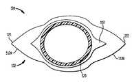
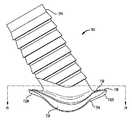
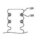
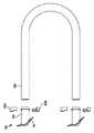
図1Aは、本発明によるフローコネクタの一実施形態における側面図である。図1Aに
おいて、フランジ102は、周縁フランジであり、導管104の第1または基端部の基端
側で導管104から半径方向に突出するよう構成する。導管104は、導管104の基端
部131でオリフィスとして終端する。第2オリフィスを、導管104の反対側における
末端部132に配置する。フランジ102は、移植するとき被移植者の源(ソース)体内
空間を画定する組織壁の内面と接触するように構成した接触面126を有する。フランジ
102の接触面126とは反対側は、源体内空間(図示せず)を通過する液体に露呈する
露出面128である。FIG. 1A is a side view of an embodiment of a flow connector according to the present invention. In FIG. 1A, the
本発明の一実施形態において、フランジ102は、複数の周方向に隣接する区域を有す
る。例えば、1対の互いに対向するフランジ区域112Aおよび112Bを設ける。体内
導管に移植する形状に設計したこれら実施形態において、フランジ区域112は長手方向
フランジと称し、フランジ区域112Aはヒール区域と称し、フランジ区域112Bはト
ウ区域112Bと称する。長手方向フランジ区域112の他に、フランジ112A,11
2Bからほぼ等距離に存在する導管104の互いに対向する側面から突出する、ほぼ同様
の1対の横方向区域114A,114Bを設ける。周方向に互いに対向するフランジ区域
114A,114Bは、長手方向フランジ区域112に対してほぼ直交するため、横方向
区域114と称し、導管104の互いに対向する側面で、図1C〜1Eにおいて示したフ
ランジ102から突出するように構成し、また、フランジ102を埋め込む源体内空間の
長手方向軸線110の周りに周方向に延在するよう構成する。横方向区域114A,11
4Bの周方向半径は、フローコネクタ100を埋め込む源体内空間領域における曲率半径
に基づいて選択する。一実施形態において、長手方向軸線110から横方向区域114A
,114Bの接触面126までに画定される半径297は、長手方向軸線110から源体
内空間の内面までに画定される半径298にほぼ等しい。他の実施形態において、長手方
向軸線110から横方向区域114A,114Bの接触面126までに画定される半径2
97は、長手方向軸線110から源体内空間の内表面までに画定される半径298より大
きいものとする。さらに、それらの実施形態において、フランジ102を形状記憶材料で
形成し、形状記憶材料から形成するフランジ102上に加わる外力が、フランジの少なく
とも一部を屈曲させるが、形状記憶材料の性質は、フランジ102をその元の形に戻す力
を生ずるようにする。横方向区域114A,Bの半径が大きいこのような実施形態におい
て、長手方向軸線110から横方向区域114A,Bの接触面126までに画定される半
径は、長手方向軸線110から源体内空間の内面までに画定される半径よりも1〜10%
大きくする。これを構成する形状記憶材料の性質と関連する横方向区域114A,Bの大
きな半径は、フローコネクタ100を源体内空間内に埋め込むとき、慢性的な外部に向か
う力を生成し、同様に、源体内空間の壁を外部に向かう力に抵抗させ、したがって、横方
向区域114A,Bに圧縮力を与える。横方向区域114A,Bに加わる圧縮力は、フラ
ンジ102の接触面126を源体内空間の組織壁における開口に向かわせ、源体内空間内
の液体をフローコネクタ100の移植後漏れないようにする。しかし、本発明の一実施形
態において、移植直後には源体内空間から液体が漏れることがある、または漏れないこと
もあることを理解されたい。しかし、通常の生理学的治癒過程では、上述の密封が組織壁
を有するフランジ102上の接触面126によって与えられるため、この漏れはすぐに止
み、したがって、液体漏れを止めるまたは防ぐため、接着剤、縫合等の付加的要素の必要
性を減少させる。In one embodiment of the invention, the
A substantially similar pair of
The circumferential radius of 4B is selected based on the radius of curvature in the source body space region in which the
, 114B to the
97 is greater than a
Enlarge. The large radius of the
接触面126およびフランジ102間の密封に加えて、上述したように、それを構成す
る形状記憶材料の性質と関連した横方向区域114A,114Bの外径も、フローコネク
タ100を支持する機能を有する。本明細書で用いる、フローコネクタ100の支持とは
、フローコネクタ100を物理的に支持し、移植位置の保持に対して他の化合物または物
質なしに移植後に源体内空間内の位置を保持することを意味する。In addition to the seal between the
本発明の一実施形態において、横方向区域114A,Bは、源体内空間の内面の周りに
周方向に延在し、源(ソース)となる源導管の内面の約180°にわたり横方向区域11
4A,Bおよびフローコネクタ100によって周方向にカバーされないままにする。約1
80°にわたりカバーされないことによって、源体内空間内における液体の流れの閉塞を
最小化するとともに、移植されたときの横方向区域114A,Bからフローコネクタ10
0によって与えられる安定性が強化される。長手方向区域112は、源体内空間の内面に
対して周方向に湾曲し、接触面が密封領域116における源体内空間の内面に接触するよ
うにし、したがって、疎水性密封およびフローコネクタ100と源体内空間との間の安定
性を生ずる。In one embodiment of the present invention, the
4A, B and the
Being not covered over 80 ° minimizes the blockage of fluid flow in the source body space, and from the
The stability provided by 0 is enhanced. The
密封領域116に隣接して補強領域118を設け、この補強領域118は、フローコネ
クタ100を源体内導管において移植するときフランジ102および導管104上に加わ
る様々な外植片または他の力に抵抗するように組み立て構成することによって、フローコ
ネクタ100を物理的に支持するように構成する。補強領域118は、転向力に抵抗する
剛性を有するよう構成し、したがって、フランジ102および/または導管104の部分
が撓み難くなる。補強領域118の剛性は、半径が増加する方向に減少し、これにより源
体内空間内にフランジ102を移植するのを支援する。剛性は、本発明の様々な実施形態
に基づいて、様々な方法で得ることができることは明らかである。例えば、補強領域11
8は、密封領域116またはフランジ102の他の部分よりも高い剛性を有する成分を持
つものとする。例えば、本発明の一実施形態において、密封領域116をショア硬度80
Aの材料で製造し、補強領域118をショア硬度55Dの材料で製造する。他の実施形態
において、補強領域118は、その隣接するまたはフランジ102の他の部分と同じ材料
で製造するが、補強領域118をフランジ102の隣接部分よりも厚くして、補強領域の
剛性をより高くする。大きな転向および屈曲を避けるため、フランジ102は、フランジ
102を挿入する源体内空間における開孔より大きくし、源体内空間からの外植または抜
けを防止する。本明細書で用いる表現である、フランジ102による大きな転向は、フラ
ンジ102の表面が、フランジ102がその転向状態においてフランジ102を挿入する
源体内空間における開孔に嵌合する大きさまで減少することを意味する。A
8 has a component having a higher rigidity than the sealing
The reinforcing
補強領域118は導管104の基端側に設け、構造的無欠性を導管104に与え、これ
により導管104の基端におけるオリフィスが、補強領域118が存在しなくてもより大
きな圧縮力に耐えることができる。さらに後述するように、補強領域118は、さらに、
フローコネクタ100に対して意図的にまたは不慮に加わる引き抜き力に対抗するのを支
援する。補強領域118は、図1A〜1Cにおいて連続したものとして示すが、本発明の
他の実施形態において、補強領域118は、連続せず、多数の補強領域118を、導管1
04の周りに配置することができることを理解されたい。同様に、補強領域118は、図
1Bにおいて示したものは、フランジ区域112,114と同様または少なくとも対応す
る外周を有するが、他の実施形態において、補強領域118は、フランジ区域112,1
14と異なる形の外周を有することができることを理解されたい。A reinforced
It helps to counter the pulling force that is intentionally or inadvertently applied to the
It should be understood that it can be placed around 04. Similarly, the reinforced
It should be understood that the outer periphery may have a shape different from 14.
長手方向区域112は、フローコネクタ100の移植を容易にするよう構成するが、さ
らに、フローコネクタを移植後、フローコネクタ100を源体内空間(図示せず)から引
き出そうとする引き出し力に対抗する。横方向区域114A,Bも、移植を容易にするよ
う構成し、さらに、フローコネクト100を移植後、源体内空間(図示せず)に対してフ
ローコネクタ100の位置を保持するよう構成する。本発明の一実施形態において、横方
向区域114A,Bは、移植する源体内空間曲率半径とほぼ一致する曲率半径を有する。
本発明の他の実施形態において、横方向区域114A,Bは、移植する源体内空間の曲率
半径よりわずかに大きい曲率半径を有する。この実施形態を源体内空間に移植するとき、
横方向区域114A,Bの大きな曲率半径によって、源体内空間は、源体内空間における
フローコネクタ100の位置の保持を促進する横方向区域114A,Bに大きな圧縮力を
生ずる。The
In other embodiments of the present invention, the
Due to the large radius of curvature of the
図1Bは、図1Aに示した1B−1B線上の断面図であり、導管本体130の大部分を
、長手方向区域112および横方向区域114の遮るものがないことを示す目的で除去し
た状態を示す。図1Bに示す実施形態において、ヒール区域112Aおよびトウ区域11
2Bは頂点を有する(図1Bの斜視図で見て)。この実施形態において、ヒール区域頂点
121およびトウ部分頂点122は、源体内空間内を流れる液体を再指向させる補助をす
るよう作用し、内膜形成および他の類似もしくは関連する条件を導く、せん断力における
乱流、渦流、フォイル効果、乱流、抵抗、管壁変形、および引張応力/歪み分布を妨げる
または最小化する。同様に、図1Aに示すように、フランジ端縁140は、例えば60°
の角度で面取りし、同じ目的で同様に源体内空間内に流れる液体を再指向させるようにす
る。FIG. 1B is a cross-sectional view taken along line 1B-1B shown in FIG. 1A, with most of the
2B has a vertex (see in the perspective view of FIG. 1B). In this embodiment, the
Chamfered at the same angle to redirect the liquid flowing into the source body space for the same purpose as well.
多数の切欠き領域124を、長手方向区域112と横方向区域114との間に配置する
。切欠き領域124は、これらフランジ112,114間の材料がないようにし、フロー
コネクタ100の移植中にフランジ112,114の一時的な折り重なり易くするように
寸法を決めまた構成する。密封領域116も、遮断領域124部分の上に配置し、導管本
体130の周囲の接触面126が源体内空間に対して確実に密封するようにし、また源体
内空間を通過する液体が源体内空間内または導管104の管腔(ルーメン)のいずれかに
存在するようにする。A number of
上述したように、フローコネクタ100は、さらに接合領域106に沿ってフランジ1
02に接続する導管104を有する。接合領域106で、導管本体130の基端部131
とフランジ102とが接続し、第1導管オリフィスが、少なくともフランジ102の露出
面128の部分を示す図1E,1Fにおいて示すように、導管本体130のオリフィス内
に通じるようにし、また、第1導管オリフィス120は導管本体130の管腔(ルーメン
)内に連通する。図1Aおよび1Bにおいて示す実施形態において、導管部分106は、
円柱状の導管本体130を有するものとして示す。しかし、当業者には、導管本体130
は、本発明の他の実施形態における円柱とは異なる形の管状形態にすることができること
明らかである。例えば、本発明の他の実施形態において、導管本体130は、長方形また
は不規則な断面を有する導管本体130およびそこに配置した同じ形の長手方向のオリフ
ィスを有する。導管本体130の基端部と反対側の端部は、導管本体130の末端部であ
り、末端部132に位置する第2導管オリフィス134を有する。例えば、静脈または動
脈とした源体内空間を導管104に接続する本発明の一実施形態において、フランジ10
2を移植する源体内空間内に流れる液体は、第1導管オリフィス120を通り、導管本体
130の管腔(ルーメン)を通り、また、第2導管オリフィス134から源体内空間に流
入するようにすることができる。As described above, the
02 has a
And the
It is shown as having a
It is obvious that the tubular shape can be different from the cylindrical shape in other embodiments of the present invention. For example, in another embodiment of the present invention, the
The liquid flowing into the source body space to implant 2 passes through the
フローコネクタ100の構成は、フローコネクタを移植する1個またはそれ以上の源導
管に基づいて異なるが、本発明の実施形態は、フローコネクタ100を有する材料、選択
した材料の硬度、本明細書で説明するまたは図面で示すフローコネクタ100の様々な部
分の厚さを、本発明の実施形態の一部として考慮する。一実施形態において、フランジ1
02は、約0.15mm〜約0.35mmの間の範囲における厚さを有する。同様に、導
管本体130の外径は、約0.15〜0.50mmの間、より好ましくは、約0.30m
m〜約0.45mmの間の範囲における同様の厚さを有する。他の実施形態において、導
管本体130の外径は、約0.35mmの厚さを有する。フランジ102の厚さを減少し
、このときフランジ102は、移植する源体内空間から引き出すフランジ100に必要な
引き出し力を維持するようにさらに突出させる。同様に、フランジ102の厚さを厚くし
、フランジ102と突出量を少なくする。Although the configuration of the
02 has a thickness in the range between about 0.15 mm to about 0.35 mm. Similarly, the outer diameter of the
Similar thicknesses in the range between m and about 0.45 mm. In other embodiments, the outer diameter of the
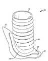
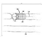
図1C〜1Fおよび図5における断面図に示すように、導管本体130は、導管本体か
ら半径方向に突出する膨大部または突出部を有する。本発明の一態様において、突出部1
29は、導管本体130の外径を周期的に増加させ、導管本体130を挿入する源体内空
間を、突出部131の増大した直径部分上の摩擦嵌合で導管本体130上に配置する。さ
らに、源体内空間を突出部131上の導管104の上に配置した後、1個またはそれ以上
の縫合を、導管130の周りおよび導管本体130と突出部131の外径部分との間の領
域で周方向に配置し、それによって、導管104に対して源体内空間を具合よく保持する
。このように、1個またはそれ以上の縫合を配置した後、導管部分104に向かって源体
内空間を圧縮する1個またはそれ以上の縫合は、導管部分104を所定位置に維持し、こ
の理由は、1個またはそれ以上の縫合が突出部の外径より小さくなるよう固定し、これに
よって、導管本体130の長手方向軸線108に沿って1個またはそれ以上の縫合が平行
移動するのを防ぐように締まり嵌めするからである。As shown in the cross-sectional views in FIGS. 1C to 1F and FIG. 5, the
29 periodically increases the outer diameter of the
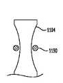
本発明のある実施形態において、図2Aおよび2Bに導管本体230として示した、導
管本体130は、その上に配置した導管窪み236を有する。導管窪み236は、図2A
および2Bにおいてフランジ202として示すフランジ102を後述するように源体内空
間内に配置するとき、源体内空間260等の源体内空間が導管窪み内に休止するように構
成する。本発明の一実施形態において、導管窪み236は、源体内空間に適合して窪みの
内に休止するよう、0.5mm〜1.0mmの間の深さを有するように構成する。本発明
の他の実施形態において、窪み236は、例えば1.0mm等の深さとなるよう構成する
。導管窪み236の高さは、フランジ202から導管本体204の末端方向に測って、約
0.8mmとし、これは、図2Aに示すように、導管窪み236内に適合する源体内空間
の厚さに依存する。また、図2Bに示すように、本発明の一実施形態の導管204は、フ
ランジ202に関して、図示の長手方向軸線に対して約60°の角度をなす。この角度は
、本発明の他の実施形態において、被移植者の状態または必要性によって異なる。例えば
、本発明の他の実施形態において、導管204は、図2Bに示した長手方向軸線に対して
10°〜90°の間の角度をなすよう構成する。当業者であれば理解できるように、この
角度はフランジ202に対して反対側に設けることができる。In one embodiment of the present invention, the
And 2B, when the
上述したように、図3にフローコネクタ300として示すフローコネクタ100は、源
体内空間内に少なくとも部分的に配置するよう構成する。図3に示す実施形態において、
フランジ102は、源体内空間360における開口303から位置決めするよう構成する
。より具体的には、1個またはそれ以上のヒール区域、トウ区域312Bおよび横方向区
域314A,Bは、一時的にフローコネクタ100に対して変形または屈曲し、これによ
りフランジ102が開口303から挿入できるようにする。開口303は、既存の開口、
または手作業でおよび/または意図的に少なくとも部分的に形成し、源体内空間内にフロ
ーコネクタ300を移植する作業中にフランジ102を挿入できるようにする。図3に示
す実施形態において、ヒール区域312Aをトウ区域312Bよりも長くする。ヒール区
域312Aのより大きい長さは、源体内空間360内におけるフランジ102の安定性お
よび位置を保持するのに役立つ。加えて、トウ区域312Bの短い長さによれば、本発明
のこの実施形態において、フランジ102の挿入をより容易にするのに役立ち、とくに、
横方向区域314A,Bのみを一時的に変形させ、長手方向区域312を、開口303か
ら大きく広がった位置で挿入する移植方法に役立つ。As described above, the
The
Alternatively, it may be manually and / or intentionally at least partially formed to allow the
Only the
図3に示す実施形態において、長手方向軸線310に沿って源体内空間360を流れる
液体は、ヒール区域312Aからトウ区域312Bの方向へ流れる。図1および3に示す
実施形態から分かるように、導管本体130の長手方向軸線108は、源体内空間360
の長手方向軸線310に対して、ヒール区域312Aに向かって約60°の角度を示す。
本発明のこの実施形態において、60°の角度を付けた源体内空間360によれば、とり
わけ、源体内空間360から導管本体330内への液体流を制御した速度および/または
体積で流すのに役立つ。本発明の他の実施形態において、角度は、60°ではない他の角
度とすることができ、それは、被移植者内におけるフローコネクタ300の配置状態また
は移植後におけるフローコネクタ300の使用目的に依存する。例えば、本発明の他の実
施形態において、導管本体330は、長手方向軸線310に対して90または120°の
角度を付け、源体内空間360からの流れを所定速度または流量にする。In the embodiment shown in FIG. 3, liquid flowing in the
With respect to the longitudinal axis 310 of FIG.
In this embodiment of the invention, the 60 ° angled
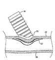
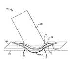
図4および5において、正中線409を有する仮想平面を、本発明の一実施形態による
、フローコネクタ400および源体内空間(図示せず)の長手方向軸線410に対して示
す。正中線409は、長手方向軸線410に対して平行であり、また、第1導管オリフィ
ス120の周りの露出面128上に位置する。図示の実施形態において、長手方向区域4
12は、図示の遷移ポイント415を起点として、正中線409から上向きに10°の角
度をなすようにする。本発明の他の実施形態において、長手方向区域412は、例えば0
〜15°の範囲内で異なる角度をなすようにする。フローコネクタ400を移植する源体
内空間の内面に向かう長手方向区域412の上向きの角度は、長手方向区域412が源体
内空間内に押し込まれる結果、1個またはそれ以上の転向力を生ずる。これらの転向力は
、長手方向区域412を下向きに転向させ、これにより長手方向区域412が正中線40
9および源体内空間の長手方向軸線410に対して、より平行となるようにする。この下
向きの転向は、転向が起こらないときよりも横方向フランジ区域414A,Bが源体内空
間の内壁により接近して配置され、また、フローコネクタ400を源体内空間内に位置決
めした後、接触面126と源体内空間の内壁との間でより広範囲の接触を生ぜしめる。図
5は、正中線409(ここでは正中線509として示す)を有する仮想平面、ならびに源
体内空間の長手方向軸線510に対して10°の角度をなす長手方向区域412(ここで
は長手方向区域512として示す)を示す。4 and 5, a virtual plane having a midline 409 is shown relative to the
12, an angle of 10 ° is formed upward from the midline 409 starting from the illustrated
Make different angles within the range of ~ 15 °. The upward angle of the
9 and the
本発明の実施形態においては、異なる形態の長手方向区域および横方向区域を有するも
のとすることができる。図6に示す実施形態において、長手方向区域612Aおよび61
2Bはほぼ同一の寸法とする。図6の実施形態では、ヒール区域612Aは、図示のよう
に、長めにし、また先端を有するものとする。トウ区域612Bは、ヒール区域612A
よりも短く、ヒール区域612Aの先端よりもより丸い先端を有するものとする。トウ区
域612Bの長さは、長いヒール区域612Aとの連係で、上述した引き抜き力に抵抗す
るのに十分であるとともに、フランジ602を源体内空間の開口(図示せず)に挿入する
のを容易にする。本発明の特定の実施形態において、区域612A,Bは、それぞれ第1
導管オリフィス620の外径寸法の約35〜65%となるようにする。本発明の代替的な
実施形態において、区域612A,Bは、第1導管オリフィス620の外径寸法の約50
%とする。Embodiments of the invention may have different forms of longitudinal and transverse sections. In the embodiment shown in FIG. 6,
2B has substantially the same dimensions. In the embodiment of FIG. 6, the
Be shorter and have a more rounded tip than the tip of the
The outer diameter of the conduit orifice 620 is about 35 to 65%. In an alternative embodiment of the present invention,
%.
同様に、図7Aおよび7Bに示す実施形態において、長手方向区域712は、互いに完
全に同一にする。図示のように、ヒール区域712Aおよびトウ区域712Bの双方は、
これまで図示および説明した他の実施形態よりも短い。図7Bは、7B−7B線上の断面
図であり、フローコネクタ700から部分的に除去した導管本体730を示す。図7Aお
よび7Bに示す本発明の実施形態は、適切に配置および寸法にし、それぞれ長手方向区域
712および横方向区域714による引き抜き力に対する補償を維持するよう構成する。
上述したように、フランジ712,714の密封領域116および補強領域118の厚さ
を増大して、フランジ712および714をより一層剛性の高いものにする。代案として
、本発明の他の実施形態において、これらの部分は、より剛性の高い材料で構成する。図
7Aおよび7Bは、さらに、切欠き領域724を示し、これら切欠き領域724によれば
、被移植者の源体内空間内にフローコネクタを移植する作業中1個またはそれ以上のフラ
ンジ712,714を一時的に寄せ集めることができるよう、フランジ712,714の
可撓性を少なくとも部分的に高める。Similarly, in the embodiment shown in FIGS. 7A and 7B, the longitudinal sections 712 are completely identical to one another. As shown, both the
It is shorter than the other embodiments shown and described so far. FIG. 7B is a cross-sectional view taken along line 7B-7B, showing the conduit body 730 partially removed from the
As described above, the thickness of the sealing
図8Aおよび8Bは、切欠き領域824がフローコネクタ800のフランジ802を有
する材料の減少量がゼロからごく僅かにしか減少しない、本発明の他の実施形態を示す。
フランジ802は、切欠き領域824の材料減少が極めて少ないまたは材料が存在するに
も係わらず、外科医が操作するピックアップツール等の外力を受けたとき容易に屈曲でき
るように構成および寸法決めする。当業者には理解されることだが、切欠き領域824お
よび他のフランジ部分802および導管部分804は、移植処置の前またはその処置中に
変更することができ、このことを以下に説明する。したがって、切欠き領域824または
長手方向区域812および横方向区域814は、生体内で変更し、源体内空間の寸法、ま
たはフローコネクタ800の移植作業中にフランジ802を挿入すべき開口に適合させる
ことができる。FIGS. 8A and 8B illustrate another embodiment of the present invention in which the
The flange 802 is configured and dimensioned so that it can be easily bent when subjected to external forces, such as a pick-up tool operated by the surgeon, even though there is very little material loss or material is present in the
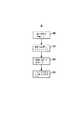
手術にあたり、本発明の実施形態は、多くの方法で移植できる。図9Aに示す手術の特
別な一つの方法において、源体内空間を、仕向け先の体内空間に流体接続する他の導管を
準備する(ステップ900)。仕向け先である体内空間、例えば被移植者の静脈を結紮し
、ついでカットし(ステップ910)、フローコネクタ100の導管104を受容する。
仕向け先体内空間に導管104を装着した後、源体内空間に開口を形成される(ステップ
920)。仕向け先体内空間に接続したフローコネクタのフランジ102を、形成した開
口から挿入し、源体内空間および仕向け先体内空間を互いに接合する(ステップ930)
。In operation, embodiments of the present invention can be implanted in a number of ways. In one particular method of surgery shown in FIG. 9A, another conduit is provided that fluidly connects the source body space to the destination body space (step 900). The internal body space that is the destination, for example, the vein of the recipient, is ligated and then cut (step 910) to receive the
After the
.
上述した方法の概略を図9Bおよび図10A〜10Hにつきさらに説明すると、本発明
の一実施形態によれば、被移植者の体内における他の導管におけるすべての分岐1003
を切断し、さもなければ図10Aに示すように、仕向け先体内空間1050から流体的に
切り離すまたは結紮する(ステップ902)。図10Bに示すように、仕向け先体内空間
1050自体を結紮し、さもなければひもまたは縫合糸1110を用いて閉塞部を形成す
る(ステップ911)。図10Cは、向き決めライン1102を仕向け先体内空間105
0上でマーク付けし、開口1104を、向き決めライン1102に沿って形成することを
示す。図10Dに示すように、フローコネクタ1000の導管部分102を、開口110
4から挿入する(ステップ914)。図10Eは2個の縫合糸1006を示し、これら縫
合糸1006は、このときフローコネクタ1000を固定した仕向け先体内空間の部分か
ら閉塞部の端部を切り取る(ステップ916)の前に仕向け先体内空間に固定する。図1
0Fにおいて、位置を特定し、源体内空間1060における開口を形成すべき場所にマー
ク付けする(ステップ922)。図10Gに示すように、開口1112を形成した(ステ
ップ924)後、フローコネクタ1000のフランジ1002を、開口1112から挿入
し、長手方向区域114および横方向区域112と連係により源体内空間1060の壁に
確実に保持することができる。The above-described method will be further described with respect to FIGS. 9B and 10A-10H. According to one embodiment of the present invention, all branches 1003 in other conduits within the recipient's body.
Or otherwise fluidly disconnected or ligated from the destination body space 1050 (step 902), as shown in FIG. 10A. As shown in FIG. 10B, the
Marked on 0 indicates that the
4 is inserted (step 914). FIG. 10E shows two
At 0F, the location is identified and the location in the
本発明の一実施形態による導管1404の一部における断面を図14に示す。図14に
示した部分は、基端部1432から末端部1432に至り、導管オリフィス1434から
流出し、仕向け先要素(図示せず)例えば血管に流入する流れを改善するようにしたラン
プ(傾斜)を示す。図14に示した部分に関して、導管1404の内径は徐々に増加し、
導管1404の外径はほぼ変化させないでおく。導管1404の内径を仕向け先要素の内
径とほぼ等しくすることによって、オリフィス1434の断面を通過する流れが可能な限
り均一または一定となるようにし、したがって、内膜過形成等の望ましくない生理学的反
応をもたらす恐れがある流れの乱流および他の外乱を最小限にする。傾斜の特徴は、導管
1404のいずれか一方の端部に設け、導管1404に対して流入および/または流出す
る流れを滑らかにすることを理解されたい。例えば、本発明の一実施形態において、傾斜
の特徴は、導管1404の両側端部に設け、導管1404の限定された長さにわたり導管
1404内への液体の流入を滑らかにし、これに続いて内径が一定である長さ部分、内径
を徐々に増大する傾斜を有する導管1404の最終末端長さ部分を設け、導管オリフィス
1434から流出する乱れのない液体流を生ずるよう補助する。A cross section of a portion of
The outer diameter of the
本発明の他の実施形態において、導管1404の外径は、基端部1431から末端部1
432まで変化する。例えば、一実施形態において、各端部の外径を、その長さに沿って
徐々に減少させる。本発明の他の実施形態において、各端部の外径は、その長さに沿って
徐々に増加させる。さらに他の実施形態において、外径は、ある長さ部分に沿って徐々に
増大させた後に、他の長さ部分に沿って減少させる。当業者には理解できるように、外径
は、特定の必要性または特定用途を満たすため、一定または様々に変化するよう調整する
ことができる。In other embodiments of the present invention, the outer diameter of the
It changes to 432. For example, in one embodiment, the outer diameter of each end is gradually decreased along its length. In other embodiments of the invention, the outer diameter of each end is gradually increased along its length. In still other embodiments, the outer diameter is gradually increased along one length portion and then decreased along another length portion. As will be appreciated by those skilled in the art, the outer diameter can be adjusted to vary constant or variously to meet specific needs or specific applications.
本発明の特定の実施形態において、導管104の第2端部は、仕向け先要素の管腔(ル
ーメン)、例えば血管におけるルーメンの内径とほぼ等しい内径を有するようにする。上
述したように、導管104の末端部および仕向け先要素の内径を、液体流が一方から他方
に遷移する各ポイントで一致させると、渦電流および流れにおける他の外乱を大幅に減少
し、これにより、凝血、血栓、内膜過形成、および極めて望ましくない他の症状の発生を
減少することができる。換言すれば、これら特徴部によって、本発明によるフローコネク
タの実施形態は解剖学的な血流、すなわち、ほとんどの循環システムを通して血流に関し
て正常な条件である層流、を修復することができる。当業者には理解できるように、層流
は、血管の長さにわたり平行に移動する血の同心状層によって特徴付けられる。換言すれ
ば、最高速度が、血管の中央で見られ、最低速度が血管壁に沿って見られる。In certain embodiments of the invention, the second end of the
他の流れの外乱には、以下のものに限定しないが、デッドフロー領域があり、これは一
般的に、ほぼ直線的な流れから派生する渦または他のタイプの流れパターンが、所定要因
、例えば流速、液体の粘性、導管104および仕向け先要素の内径等に関して急段差また
は直径変化の急勾配によって形成される。本発明の他の実施形態において、導管104は
、面取りした末端部132または徐々にテーパを付けた末端部132を設け、この末端部
132で内径を仕向け先導管の開口に近づくにつれて徐々に増大させる。本発明の他の実
施形態において、導管104は、仕向け先導管の基端側オリフィス134をナイフ状端縁
で終端させ、このナイフ状端縁では仕向け先要素基端部に向かって壁厚がゼロに近づく。Other flow disturbances include, but are not limited to, dead flow regions, which are typically vortices or other types of flow patterns that are derived from a nearly linear flow, which are pre-determined factors such as It is formed by a steep step or a steep change in diameter with respect to flow velocity, liquid viscosity, inner diameter of
図1Fおよび図13〜15に示すように、導管104(さらに導管1304,1404
,1504)の内面は、摩擦を受けずに表面上を液体が流れることができるほぼ無摩擦表
面とする。この滑らかな表面は、無摩擦表面でない場合には導管104を流れる間に生ず
る可能性がある乱流を減少またはなくすことができる。As shown in FIG. 1F and FIGS.
, 1504) is an almost frictionless surface that allows liquid to flow over the surface without friction. This smooth surface can reduce or eliminate turbulence that may occur during flow through the
図12Bは、湾曲部1260を導管1204に沿うポイントに設けた、本発明の他の実
施形態を示す。導管1204における湾曲部1260の内表面は、フランジ1202から
仕向け先要素、例えば血管まで導管1204を通る液体の向きを転向させる。図12Bに
示す実施形態において、湾曲前の第1長手方向軸線1266を、湾曲後の第2長手方向軸
線1268とともに示す。図示の実施形態において、フランジ1202から湾曲前の第1
部分1265を流れる液体は、液体が湾曲後の第2部分1267に流入する前に湾曲部1
260によって向きが転向する。このように液体の向きが変わると、湾曲部1260にお
ける導管1204は、仕向け先要素(図示せず)に向かって転向するとき、湾曲部126
0に向かって流れる液体からの力を吸収し、これら力が体内血管に加わるのを防ぎ、湾曲
部がないとこれら力を体内血管が受けることになる。上述したように1個またはそれ以上
の湾曲部1260を有する本発明の実施形態を使用することにより、源体内空間と仕向け
先要素との間における接続を改善することができる。例えば、源体内空間が動脈であり仕
向け先要素が静脈であるとき、図10A〜10Hにおける本発明の異なる実施形態につき
示したように、フローコネクタ1200Bを使用して、体内空間または静脈1050を、
体内空間または動脈1060に接続するが、静脈1050は必ずしも図10Hに示すよう
に曲げる必要はない。代わりに、コネクタ1200Bは、動脈1060から突出し、静脈
1050の開口に向かって湾曲する湾曲部1260を設け、静脈1050を、ほぼ直線の
ままとすることができる。FIG. 12B shows another embodiment of the invention in which a
The liquid flowing through the
The direction is turned by 260. Thus, when the orientation of the liquid changes, the
Absorbing forces from the liquid flowing toward zero, preventing these forces from being applied to the body blood vessels, and if there are no curved portions, the body blood vessels receive these forces. By using an embodiment of the invention having one or
Although connected to body space or
本発明の他の実施形態において、図15に示すように、導管1504の末端部1532
は傾斜させ、末端部1532でのオリフィス1534は導管1504の長手方向軸線に対
して90°ではない角度をなす。図示の実施形態において、傾斜した末端部1532は、
導管1504の長手方向軸線に直交する平面に対して約30°の角度をなす。しかし、当
業者であれば、その角度は本発明の実施形態を用いる条件によって異なることを理解でき
るであろう。傾斜した末端部1532は、導管1504における湾曲部の方向に流れる液
体のより早期の流出を可能にすることによって仕向け先要素における湾曲部に適合して、
液体が導管1504を通り、傾斜した末端部1532から仕向け先要素に流出する遷移を
良好にする。例えば、図15に示す実施形態は、傾斜した端部1532を有し、これによ
りオリフィス1534は左に向かってバイアスされる。この左向きのオリフィス1534
は、仕向け先要素を接合し、また導管1504から延びて、左側に向って湾曲する箇所に
用いる。導管1504から早期流出させることの他に、傾斜した末端部1532は、さら
に、仕向け先要素、例えば導管または血管における湾曲部が血管の内面を収縮または縮径
させる状況を少なくする。In another embodiment of the present invention, as shown in FIG.
And the
An angle of about 30 ° with respect to a plane perpendicular to the longitudinal axis of the
The transition through which the liquid flows through the
Is used where the destination element is joined and extends from the
本発明のさらに他の実施形態において、源体内空間および仕向け先要素は、異なる外径
を有し、これら外径は、異なる外径に適合するように構成する。図13に示すように、本
発明の一実施形態によれば、導管1304の外径は、基端部1331から末端部1332
まで変化する。図示のように、導管1304の内径も、導管1304の外径における変化
と同じ割合で増加する。しかし、本発明の他の実施形態において、内径は、外径における
変化と同様に、異なる割合で変化させる、または変化させないようにすることができる。In yet another embodiment of the present invention, the source body space and the destination element have different outer diameters that are configured to fit different outer diameters. As shown in FIG. 13, according to one embodiment of the present invention, the outer diameter of the
Change to. As shown, the inner diameter of
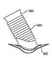
図17A,Bおよび18A,Bに示すように、本発明の他の実施形態によれば、フロー
コネクタ1700および1800は、折り畳み可能(図17A,B)または拡開可能(図
18A,B)にし、源体内空間および仕向け先要素の内径における変化によりよく適合で
きるようにする。さらに、折り畳み可能および拡開可能な実施形態を使用して移植を支援
することができ、この場合、物理的に寸法を縮小させつつ導管1704,1804を移植
し、つぎにより大きい形状に復元させ、仕向け先空間または源体内空間に装着、例えば密
封および保持させる力となる(またはできる)。導管1704および1804はメッシュ
材料で形成し、このメッシュ材料は、様々なジョイント、ヒンジまたは操作可能な一連の
部分を有し、導管1704,1804の全体形状を操作できるようにする。拡開可能な導
管1704は、図17Aに示すように、小さな断面形状を有する形態にし、その後図17
Bに示すように、強制的に拡開した断面形状に復元することができる。本発明の一実施形
態において、拡開可能な導管1704は、移植した導管1704内に挿入して膨張するバ
ルーンによって拡開することができる。本発明の他の実施形態において、拡開可能な導管
1704は、導管1704の拡開する部分に連通する基端部1731に機械的な拡開力を
加えるようにし、これにより図17Bに示すように導管1704を開く。図示の実施形態
において、導管1704は、図17Aに示すように順次にオーバーラップするが、図17
Bに示すように拡開して分離する指状部分を有するものとする。指状部分の一部を使用し
て、仕向け先体内空間を保持するとともに、異なる部分を使用して、導管1704と仕向
け先体内空間との間を密封することができることを理解されたい。As shown in FIGS. 17A, B and 18A, B, according to another embodiment of the present invention, the
As shown to B, it can restore | restore to the cross-sectional shape expanded forcibly. In one embodiment of the invention, the
As shown in B, it has a finger-like portion that expands and separates. It should be understood that a portion of the finger portion can be used to hold the destination body space and a different portion can be used to seal between the
同様に、折り畳み可能な導管1804は、形状記憶材料により、メッシュまたは他の形
態として構成し、静止時に拡開するが十分な力を加えるとき折り畳むことができるように
する。図18A,Bに示すように、導管1804の一部は、折り畳み可能な部分を構成し
、他の部分は折り畳み不可能な部分とする。本発明の一実施形態において、折り畳み可能
な導管1804は送給管(図示せず)内に配置し、この送給管は、導管を折り畳み状態に
して収容してから、仕向け先体内空間に挿入および送給する。本発明の他の実施形態にお
いて、送給管(図示せず)は、再吸収可能な材料で形成し、これにより折り畳み可能な導
管1804を再吸収可能な送給管内で仕向け先体内導管内に送給される。送給後に、再吸
収可能な送給管は、再吸収を開始し、折り畳み可能な導管1804が釈放され、その自然
な拡開した形態に復元する。Similarly, the
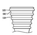
本発明の実施形態によれば、図11Kおよび11Lに示すように、導管1104は、工
場生産の後に変更または短縮することができる。例えば、本発明の一実施形態によれば、
導管1104は、外科医が体内で、導管1104の末端部を挿入する、例えば静脈等の仕
向け先要素における開口を評価することができるよう構成する。導管の短縮しようとする
位置またはその周辺を心理的にまたは物理的にマーク付けした後、外科医は、末端部13
2から材料を切除し、フローコネクタ100を仕向け先要素により良好に適合させる。本
発明の他の実施形態において、導管1104は、1個もしくはそれ以上の窪み1181に
おける穿孔、または突出部1129のような視覚的なマーカーを設け、これにより切除ま
たは除去する部分を測定し易くする。本発明の特別な実施形態において、導管1104の
外側のマーカーは、0.25mm、0.5mmまたは1.0mm等の増分で導管1104
をカットするのを容易にする。本発明の他の実施形態において、導管1104に沿う穿孔
は、0.25mm,0.5mmまたは1.0mmのそれら増分だけ導管1104を切除ま
たは変更するのを容易にする。導管1104は、弾性的な可撓性がある材料、例えばシリ
コーンまたは弾性的な可撓性がある他の材料で構成することができ、このことは当業者に
は理解できるであろう。代案として、導管1104は、剛性のあるまたは硬質なものにす
るため、1個またはそれ以上の材料で形成することができるが、この場合、導管1104
を弾性的な可撓性がある本発明の実施形態よりも、短縮または変更するために異なるツー
ルが必要となる。According to embodiments of the present invention, as shown in FIGS. 11K and 11L, the
The
Cut material from 2 to better match the
Make it easy to cut. In other embodiments of the invention, perforations along the
A different tool is needed to shorten or modify the embodiment of the present invention, which is elastic and flexible.
さらに、本発明のある実施形態は、1個またはそれ以上の活性要素を導管104または
フランジ102に設け、1個またはそれ以上の治療効果を生ずるよう構成する。例えば、
本発明の一実施形態において、フローコネクタ100は、一つの材料で形成し、フローコ
ネクタ100の1個またはそれ以上の部分をX線不透過性とする。本発明の他の実施形態
において、活性要素は、フローコネクタ100が放出し、フローコネクタの近傍領域また
は被移植者に対して系統的に作用するよう構成した、1種類またはそれ以上の薬剤化合物
または医薬材料とする。本発明のある実施形態において、1種類またはそれ以上の医薬材
料は、放出を始めるために、加熱または液体接触させる必要があるよう構成する。本発明
の他の実施形態において、フローコネクタ100における医薬材料は、さらに、経時放出
するよう構成し、これにより、含まれる化合物がある期間にわたり一定にまたは放出速度
が変化して徐々に放出される。本発明のさらに他の実施形態において、活性要素は、加熱
または液体接触によって活性化した溶解カプセル殻内に詰めた医薬材料とする。Further, certain embodiments of the present invention are configured to provide one or more active elements in the
In one embodiment of the present invention, the
図12Bに示すように、本発明の他の実施形態は、十分な外力を受ける際に異なる形状
になり、そしてこの形状を保持する従順性を持つ導管1204を有する。例えば、本発明
の一実施形態において、外科医は、導管1204に曲げ力を加え、源および仕向け先の体
内導管に適合させる。外科医から十分な曲げ力を受けると、導管1204は、湾曲部を保
持し、導管1204の形状、とくに内面に沿って導管内を流れる流体を転向または案内す
る。従順性導管1204は、メッシュまたは形状記憶金属のような協調要素を有する他の
構造で構成し、これにより、従順性導管1204は上述した曲げ力を受ける際に形状を保
持することができる。As shown in FIG. 12B, another embodiment of the present invention has a
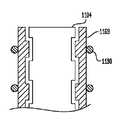
本発明の実施形態は、導管1104の末端部1132における仕向け先要素(図示せず
)の保持を支援するよう構成する。本発明のある実施形態において、図11Aおよび11
Bに示すように、突出部1129を、導管1104の外面の周りに周方向に配置する。図
11Aは、導管1104を簡略化した輪郭図を示し、導管1104の周りに配置した半径
方向突出部1129のシルエットを示す。図11Bは、導管1104の外面に配置または
外面から突出する複数の押出部または突起を示す。図11Mに示すように、本発明の他の
実施形態によると、導管1104における複数の半径方向突出部1129は、導管110
4の長さの大部分にわたり、または少なくとも一区域、例えば末端部区域にわたり設ける
ことができる。本発明の他の実施形態によれば、突出部1129は、別個のカラー上に配
置し、またフローコネクタ1100を移植する前にこのカラーを導管1104に配置する
ことができる。図11Pおよび11Q示すように、保持突出部1129は、均一または簡
素にする必要はない。マトリクス状の突出部構成1129を、図11Pに本発明の他の実
施形態として示す。本発明のさらに他の実施形態において、正弦曲線状の突出部1129
を、図11Qに示す。Embodiments of the present invention are configured to assist in retaining a destination element (not shown) at the
As shown in B, the
It can be provided over most of the length of 4 or at least over one area, for example the end area. According to other embodiments of the present invention, the
Is shown in FIG. 11Q.
本発明の他の実施形態において、導管1104の表面設けた保持特徴部は、表面処理と
することができる。図11Oに示す本発明の例示的な実施形態において、導管1104の
外面にディンプルまたは凹みを付け、処理した外面が保持能力を持つようにする。ディン
プルまたは凹みを付ける表面処理の大きさに依存して、外面は、例えば、血管等の仕向け
先要素の内面に摩擦を生ずることができる。他の保持特徴部を、導管1104の外面に設
けることができる。例えば、本発明の他の実施形態において、複数の逆とげ1229また
は他の鋭い突起を導管1204の外面に配置する。逆とげ1229は、少なくとも部分的
に、仕向け先要素、例えば血管の壁に貫入し、導管1204に対して要素を保持的に固定
するようにする。本発明の他の実施形態において、逆とげ1229は、導管1204に対
して仕向け先要素を保持的に固定する一方で、仕向け先要素に貫入する。In other embodiments of the present invention, the retention feature provided on the surface of the
フローコネクタ100,200は、さらに、本発明のさらに他の実施形態による図1D
および2Bに示すように、接合領域106に隣接する導管104における休止面136,
236を有する。図1Dに示す実施形態において、休止面136は、フランジ102を移
植した後、休止面136の周りで源体内空間の壁を受け止めるよう構成した、導管本体1
04の窪みである。図示の実施形態において、休止面136は、ほぼ滑らかであり、また
、仕向け先要素を突出部129の上に配置した後には、仕向け先要素を保持するよう構成
した上述の突出部129が存在しない部分である。図1Dおよび2Bに示す実施形態にお
いて、休止面136は、湾曲部分を有する形状であり、また源体内空間227を図2Bで
、休止面136の湾曲した形状に一致するものとして示す。しかし、体内空間227の図
2Bで示す湾曲の程度は、例示目的のため誇張しており、図示の曲率の程度を常にとるわ
けではない。The
And 2B, the
236. In the embodiment shown in FIG. 1D, the
It is a hollow of 04. In the illustrated embodiment, the resting
上述の突出部を使用して、突出部に装着する際に仕向け先要素を保持することの他に、
突出部は、図10E,11A〜11Nに示した実施形態のように、縫合糸または固定カラ
ーまたはそれらの組み合わせ等の1個またはそれ以上の保持要素を収容するためにも用い
る。図10Eは、2個の縫合糸を、仕向け先要素、例えば静脈に配置し、導管1004の
外面に沿って配置した窪みに向けて静脈を圧縮する、本発明の一実施形態を示す。図11
Aは、複数の隣接する突出部1129が、連係して突出部間に山形窪みを形成する一つの
実施形態を示し、これら山形の窪み内に縫合糸1190のような保持要素が、図11E,
11F,11I,11Jに示すように、少なくとも部分的に仕向け先要素を圧縮する。図
11Bにおいて示す実施形態において、保持要素は、仕向け先要素、例えば静脈の組織壁
を突起1129間のスペースに圧縮する。図11C,11D,11G,11Hに示す本発
明の実施形態において、固定カラー1169を、仕向け先要素、例えば静脈の組織壁の、
固定カラー1169および導管1104の間に位置する部分に使用し、仕向け先要素を導
管1104に固定する。本発明のある実施形態において、仕向け先要素部分は、固定カラ
ー1169によって導管1104の外面に対して圧縮することができる。本発明の他の実
施形態において、固定カラー1169は、仕向け先要素部分を導管1104の外面に沿っ
て相応に形成した窪み内に圧入し、窪みと固定カラー1169との間における締まり嵌め
が仕向け先要素部分を導管1104に保持するようにする。複数の突出部1129は、本
発明のある実施形態による導管1104の長さに沿って配置して、外科医が、仕向け先要
素を導管1104に固定するのに用いる広範囲にわたる突出部1129の選択をすること
ができるが、突出部1129は、さらに導管1104を簡素化するため離れた位置に設け
ることができ、この場合、外科医は少ない個数、例えば本発明の一実施形態による図11
Nに示す2個の突出部1129を設けることもできる。図11Nに示すように、突出部1
129は、導管1104の滑らかな外面からフレア状に突出し、突出部1129より小さ
な半径にした縫合糸1190等の固定要素を、導管1104の基端部1131により近い
位置に配置し、締まり嵌めが縫合糸1190と突出部1129との間に形成されるように
する。このような実施形態において、仕向け先要素を導管1104に保持するよう作用す
る1個またはそれ以上の縫合糸に加えて、導管1104の末端部におけるフレア自体は、
仕向け先要素を導管に保持する圧嵌を生ずるのに十分である。この圧嵌は、導管1104
から仕向け先要素に流れる漏れを防ぐ機能も果たす。本発明の代替的な実施形態において
、フレア部分1129(先には突出部1129と称していた)は、導管1104とは別個
の部分として構成し、これにより導管1104は、フレア部分1129の長手方向軸線の
周りを360°回転することができるとともに、フレア部分1129は、静止したまま、
仕向け先要素に固定した状態を維持することができる。In addition to holding the destination element when mounted on the protrusion, using the protrusion described above,
The protrusions are also used to accommodate one or more retaining elements, such as sutures or securing collars or combinations thereof, as in the embodiment shown in FIGS. 10E, 11A-11N. FIG. 10E illustrates one embodiment of the present invention in which two sutures are placed in a destination element, eg, a vein, and the vein is compressed toward a depression placed along the outer surface of the
A illustrates one embodiment in which a plurality of
As shown in 11F, 11I, 11J, the destination element is at least partially compressed. In the embodiment shown in FIG. 11B, the retention element compresses the destination element, eg, the tissue wall of the vein, into the space between the
Used in the portion located between the
It is also possible to provide two projecting
129 protrudes in a flared shape from the smooth outer surface of the
Sufficient to produce a press fit that holds the destination element to the conduit. This press fit is caused by
It also functions to prevent leakage from flowing to the destination element. In an alternative embodiment of the present invention, the flare portion 1129 (previously referred to as the protrusion 1129) is configured as a separate portion from the
The state fixed to the destination element can be maintained.
本発明の実施形態は、図19に示すように、本明細書で説明したフローコネクタを人工
導管1999に接続するのに使用することができることを理解されたい。図示のように、
第1フローコネクタ1900を、人工導管1999に結合し、また固定カラー部品126
9A,Bによって保持するよう構成する。固定カラー部品1269A,Bは、それぞれ導
管の外面における相応形状の突出部の周りに装着するよう、窪み等の保持特徴部を有する
構成とする。図19に示す実施形態において、人工導管1999の各端は、導管1904
と固定カラー1269との間に位置決めし、フローコネクタの各フランジ1902は、同
一または異なる体内空間内に移植し、これによりフローコネクタ1900を流体接続する
。このように、フローコネクタ1900を、バイパスまたは他の処置に使用し、このこと
は流体接続ならびに、とりわけ自己封止および自己支持特性を生ずる1個またはそれ以上
のフランジから利点が得られる。It should be understood that embodiments of the present invention can be used to connect the flow connector described herein to an
The first flow connector 1900 is coupled to the
9A and B are used for holding. The fixed
And each flange 1902 of the flow connector is implanted in the same or different body space, thereby fluidly connecting the flow connector 1900. Thus, the flow connector 1900 is used for bypass or other procedures, which benefits from a fluid connection and, in particular, one or more flanges that produce self-sealing and self-supporting properties.
本発明の実施形態は、2個の組織包囲体内空間、例えば静脈および動脈、を接続するの
に使用するものとして広範囲に説明したが、本発明の他の実施形態を使用して、体内空間
を、人工装置、例えばポンプ、フローコネクタ100に接続した人工導管、導管102、
センサー、プラグ等に接続する。While embodiments of the present invention have been extensively described as used to connect two tissue-enclosing body spaces, such as veins and arteries, other embodiments of the present invention can be used to , Artificial devices such as pumps, artificial conduits connected to the
Connect to sensors, plugs, etc.
本明細書で説明しまた請求した発明は、ここで説明した特別な好ましい実施形態によっ
て範囲を限定するものではなく、これら実施形態は、本発明のいくつかの態様を説明する
ことを意図し、限定するものではない。任意の等価な実施形態も、本発明の範囲内である
ことを意図する。実際、図示および説明したのに加えて本発明の変更形態は、当業者には
明らかであろう。これら変更形態も、添付した特許請求の範囲内であることを意図する。The invention described and claimed herein is not to be limited in scope by the specific preferred embodiments described herein, which are intended to illustrate some aspects of the present invention, It is not limited. Any equivalent embodiments are intended to be within the scope of this invention. Indeed, variations of the invention in addition to those shown and described will be apparent to those skilled in the art. These modifications are also intended to be within the scope of the appended claims.
概要
本発明の一つの態様によれば、組織で包囲された体内空間を体内導管に流体接続する埋め込み型フローコネクタを開示し、このフローコネクタは、体内空間の組織壁に形成した開口から体内空間に埋め込み可能な導管の第1端部におけるオリフィスで終端するルーメンを有する導管であって、この導管の第2端部を、体内導管の表面における開口から体内導管に埋め込み可能にし、導管は体内空間から外方に延在する管状の導管本体部を有し、体内導管が導管本体部の長手方向において導管本体部の外面に沿って延在し、導管本体部の外面で体内導管を保持する、該導管と、および導管の第1端部の基端側で導管から半径方向に拡大し、体内空間の組織壁における開口に隣接するよう体内空間に埋め込み、これにより、導管が前記開口に貫通するよう構成した、周方向のフランジであって、1個またはそれ以上の周方向に隣接する区域を有し、これら区域のうち少なくとも1個は、フランジの導管からの半径方向距離が増加するにつれて剛性が低下する、該フランジと、前記導管本体部の径方向外側に位置し、前記導管本体部が埋め込まれた前記体内導管の周りを少なくとも部分的に固定可能に包み込むよう構成した保持要素と、を備える。
According to one aspect of the Summary of the Invention, anenclosed body space in tissue implantable flow a connector fluidly connecting disclosedbody conduit, the flowconnector or opening formed in a tissue wall of thebody space a conduit having a lumen terminating at an orifice in the first end portion of the possible conduits embedded inLuo body space, the second end of the conduit, the implantable into thebody conduit through an opening in the surface of thebodyconduit,The conduit has a tubular conduit body extending outwardly from the body space, the body conduit extending along the outer surface of the conduit body in the longitudinal direction of the conduit body, and the body conduit on the outer surface of the conduit body It holds anda conduit, and to expand radially from the conduit at the proximal end of the first end of theconduit, embedded bycormorants body space adjacent to the opening in the tissue wall of abody in space, thereby, A conduit to the opening A circumferential flange configured to penetrate, having one or more circumferentially adjacent areas, at least one of which increases the radial distance from the conduit of the flange. A flange anda retaining element that is positioned radially outward of the conduit body and is configured to at least partially fixably wrap around the body conduit in which the conduit body is embedded. , comprising a.
本発明の他の態様によれば、組織で包囲された体内空間を体内導管に流体接続する埋め込み型フローコネクタを提供し、このフローコネクタは、体内空間の組織壁に形成した開口から体内空間に埋め込み可能な導管の第1端部におけるオリフィスで終端するルーメンを有する導管であって、この導管の第2端部を、体内導管の表面における開口から体内導管に埋め込み可能にし、導管は体内空間から外方に延在する管状の導管本体部を有し、体内導管が導管本体部の長手方向において導管本体部の外面に沿って延在し、導管本体部の外面で体内導管を保持する、該導管と、および導管の第1端部の基端側で導管から半径方向に拡大し、体内空間の組織壁における開口に隣接するよう体内空間に埋め込み、これにより、導管が開口に貫通するよう構成した、周方向のフランジであって、導管を補強するよう構成および配置した1個またはそれ以上の周方向に隣接する区域を有する、該フランジと、前記導管本体部の径方向外側に位置し、前記導管本体部が埋め込まれた前記体内導管の周りを少なくとも部分的に固定可能に包み込むよう構成した保持要素と、を備える。
According to another aspect of the present invention, anenclosed body space organization provides implantable flow connector for fluidly connecting to thebody conduit, the flowconnector, an opening orwe formed in a tissue wall of thebody space a conduit having a lumen terminating at an orifice in the first end portion of the implantable conduitbody space, the second end of the conduit, the implantable into thebody conduit through an opening in the surface of thebodyconduit,the conduit Has a tubular conduit body extending outwardly from the body space, the body conduit extending along the outer surface of the conduit body in the longitudinal direction of the conduit body, and the body conduit is formed on the outer surface of the conduit body. holding the conduit, and to expand radially from the conduit at the proximal end of the first end of theconduit, embedded bycormorants body space adjacent to the opening in the tissue wall of abody in space, thereby, the conduit Will penetrate the opening Configuration was, a circumferential direction of the flange has one or more areas adjacent in the circumferential direction which is constructed and arranged so as to reinforce the conduit, and the flangeis located radially outwardly of the conduit body portion A retaining element configured to at least partially fixably wrap around the body conduit in which the conduit body is embedded .
本発明のさらに他の態様によれば、組織で包囲された体内空間を体内導管に流体接続する埋め込み型フローコネクタを提供し、このフローコネクタは、体内空間の組織壁に形成した開口から体内空間に埋め込み可能な導管の第1端部におけるオリフィスで終端するルーメンを有する導管であって、この導管の第2端部を、体内導管の表面における開口から体内導管に埋め込み可能にし、導管は体内空間から外方に延在する管状の導管本体部を有
し、体内導管が導管本体部の長手方向において導管本体部の外面に沿って延在し、導管本
体部の外面で体内導管を保持する、該導管と、および導管の第1端部の基端側で導管から半径方向に拡大し、体内空間の組織壁における開口に隣接するよう体内空間に埋め込み、これにより、導管が開口に貫通するよう構成した、周方向のフランジであって、体内空間の長手方向軸線の周りに延在して体内空間の組織壁に衝合するよう構成した、周方向に互いに対向する1個またはそれ以上のフランジ区域を有し、またさらに、前記組織壁に衝合するよう配置される前記フランジ区域の横方向区域によって生ずる力が、前記フローコネクタを開口に向けて押圧し、これによって、前記フローコネクタを、前記フランジ区域によって支持するようにした、該フランジと、前記導管本体部の径方向外側に位置し、前記導管本体部が埋め込まれた前記体内導管の周りを少なくとも部分的に固定可能に包み込むよう構成した保持要素と、を備える。
According to still another aspect of the present invention, anenclosed body space organization provides implantable flow connector for fluidly connecting to thebody conduit, the flowconnector or opening formed in a tissue wall of thebody space a conduit having a lumen terminating at an orifice in the first end portion of the possible conduits embedded inLuo body space, the second end of the conduit, the implantable into thebody conduit through an opening in the surface of thebodyconduit,The conduit has a tubular conduit body that extends outwardly from the body space.
And the body conduit extends along the outer surface of the conduit body in the longitudinal direction of the conduit body,
Holding a body conduit at the outer surface of the body portion, the conduit and, and expanded radially from the conduit at the proximal end of the first end of theconduit,the Hare by adjacent opening in the tissue wall of thebody spacesomatic embedded in the space, thereby, the conduit is configured to penetrate into the opening, a circumferential direction of theflange, so that abutmentextending about the longitudinal axis of thebody in space to the tissue wall of thebody space A force generated by a transverse section of the flange section having one or more flange sections that are configured to oppose each other in a circumferential direction and that is arranged to abut against the tissue wall is the flow connector. Is pressed against the opening so that the flow connector is supported by the flangesection and located radially outside the flangebody and theconduit body is embedded. Previous Anda retaining element configured at least partially fixable enclose as about a body conduit.
Claims (157)
Translated fromJapaneseにおいて、
前記源体内空間の組織壁に形成した開口から源体内空間に埋め込み可能な導管の第1端
部におけるオリフィスで終端するルーメンを有する導管であって、この導管の第2端部を
、前記仕向け先要素の表面における開口から前記仕向け先要素に埋め込み可能にした、該
導管と、および
前記導管の第1端部の基端側で前記導管から半径方向に拡大し、前記源体内空間の組織
壁における開口に隣接するよう前記源体内空間に埋め込み、これにより、前記導管が前記
開口に貫通するよう構成した、周方向のフランジであって、1個またはそれ以上の周方向
に隣接する区域を有し、これら区域のうち少なくとも1個は、前記フランジの導管からの
半径方向距離が増加するにつれて剛性が低下する、該フランジと、
を備えた、埋め込み型フローコネクタ。In an implantable flow connector that fluidly connects a source body space surrounded by tissue to a destination element,
A conduit having a lumen that terminates in an orifice at a first end of a conduit that is implantable into a source body space from an opening formed in a tissue wall of the source body space, wherein the second end of the conduit is connected to the destination A conduit that is embeddable in the destination element from an opening in a surface of the element, and radially expands from the conduit on a proximal side of the first end of the conduit, in a tissue wall of the source body space A circumferential flange configured to be embedded in the source body space adjacent to an opening, thereby allowing the conduit to penetrate the opening, and having one or more circumferentially adjacent areas At least one of these areas has a flange that decreases in rigidity as the radial distance from the conduit of the flange increases; and
Embedded flow connector with
向に隣接する区域は、
第1剛性を有する第1区域と、
第2剛性を有する第2区域と
を有し、前記第1区域の剛性は、前記第2区域の剛性よりも高いものとした、埋め込み型
フローコネクタ。The implantable flow connector of claim 1, wherein the one or more circumferentially adjacent areas are:
A first zone having a first stiffness;
And a second section having a second rigidity, wherein the rigidity of the first section is higher than the rigidity of the second section.
成は、ほぼ同一とし、またさらに、前記第1および第2の区域の厚さを異なるものとした
、埋め込み型フローコネクタ。3. The implantable flow connector according to claim 2, wherein the compositions of the first and second areas are substantially the same, and the thicknesses of the first and second areas are different. Flow connector.
成は、異なるものとし、またさらに、前記第1および第2の区域の厚さをほぼと同一とし
た、埋め込み型フローコネクタ。3. The implantable flow connector according to claim 2, wherein the composition of the first and second areas is different, and further, the thickness of the first and second areas is substantially the same. Type flow connector.
りに位置し、前記第2区域は、前記第1区域よりも導管の末端寄りに位置するものとした
、埋め込み型フローコネクタ。The implantable flow connector according to claim 2, wherein the first section is located closer to the proximal end of the conduit, and the second section is located closer to the distal end of the conduit than the first section. Embedded flow connector.
長は異なるものとした、埋め込み型フローコネクタ。6. The embedded flow connector according to claim 5, wherein the first and second sections have different peripheral lengths.
管を補強するのに十分なものとした、埋め込み型フローコネクタ。2. The implantable flow connector according to claim 1, wherein the stiffness of the first section is sufficient to reinforce the conduit.
向に隣接する区域は、前記導管の周りに連続的な表面を形成するものとした、埋め込み型
フローコネクタ。The implantable flow connector according to claim 1, wherein the one or more circumferentially adjacent areas form a continuous surface around the conduit.
向け先体内空間とした、フローコネクタ。2. The flow connector according to claim 1, wherein the destination element is a destination body space surrounded by tissue.
向け先体内空間の組織壁における人工的な開口とした、フローコネクタ。The flow connector according to claim 9, wherein the opening in the destination body space is an artificial opening in a tissue wall of the destination body space.
した端部におけるオリフィスとした、フローコネクタ。10. A flow connector according to claim 9, wherein the artificial opening is an orifice at the cut end of the destination body conduit.
タ導管を埋め込む前記仕向け先体内導管の領域の内径とほぼ同一の外径を有するものとし
た、フローコネクタ。10. The flow connector according to claim 9, wherein the flow connector conduit has an outer diameter that is substantially the same as an inner diameter of a region of the destination body conduit that embeds the flow connector conduit.
ローコネクタ。The flow connector according to claim 1, wherein the destination element is a medical device.
、非円筒状とした、フローコネクタ。The flow connector according to claim 1, wherein the lumen extending in the longitudinal direction is non-cylindrical.
分として形成し、また互いに結合するものとした、フローコネクタ。2. The flow connector according to claim 1, wherein the conduit and the flange are formed as separate parts and are coupled to each other.
ンジの折り畳みを促進して開口への挿入を容易にする、1個またはそれ以上の切欠き領域
を有するものとした、フローコネクタ。The flow connector according to claim 1, further comprising one or more notch regions disposed on the flange to facilitate folding of the flange to facilitate insertion into the opening. Flow connector.
た、フローコネクタ。The flow connector according to claim 1, wherein the outer edge of the flange is chamfered.
ルーメンの長手方向軸線は、前記フランジの長手方向軸線に対して約10°〜90°の角
度をなすものとした、フローコネクタ。The flow connector according to claim 1, wherein the longitudinal axis of the longitudinally extending lumen in the conduit forms an angle of about 10 ° to 90 ° with respect to the longitudinal axis of the flange. Flow connector.
ルーメンの長手方向軸線は、前記フランジの長手方向軸線に対して約60°の角度をなす
ものとした、フローコネクタ。The flow connector of claim 1, wherein a longitudinal axis of the longitudinally extending lumen in the conduit forms an angle of about 60 degrees with respect to the longitudinal axis of the flange.
1導管のオリフィスと同一の仮想平面からテーパを付け、このテーパ角度は、前記仮想平
面から0°よりも大きい角度をなすものとした、フローコネクタ。2. The flow connector according to claim 1, wherein the one or more areas taper from the same virtual plane as the orifice of the first conduit, the taper angle being greater than 0 ° from the virtual plane. An angled flow connector.
前記テーパ角度を、約10°とした、フローコネクタ。21. A flow connector according to claim 20, wherein the taper angle of the longitudinal section from the imaginary plane is about 10 degrees.
において、
前記源体内空間の組織壁に形成した開口から源体内空間に埋め込み可能な導管の第1端
部におけるオリフィスで終端するルーメンを有する導管であって、この導管の第2端部を
、前記仕向け先要素の表面における開口から前記仕向け先要素に埋め込み可能にした、該
導管と、および
前記導管の第1端部の基端側で前記導管から半径方向に拡大し、前記源体内空間の組織
壁における開口に隣接するよう前記源体内空間に埋め込み、これにより、前記導管が前記
開口に貫通するよう構成した、周方向のフランジであって、導管を補強するよう構成およ
び配置した1個またはそれ以上の周方向に隣接する区域を有する、該フランジと、
を備えた、埋め込み型フローコネクタ。In an implantable flow connector that fluidly connects a source body space surrounded by tissue to a destination element,
A conduit having a lumen that terminates in an orifice at a first end of a conduit that is implantable into a source body space from an opening formed in a tissue wall of the source body space, wherein the second end of the conduit is connected to the destination A conduit that is embeddable in the destination element from an opening in a surface of the element, and radially expands from the conduit on a proximal side of the first end of the conduit, in a tissue wall of the source body space One or more circumferential flanges configured to be embedded in the source body space adjacent to the opening so that the conduit penetrates the opening and configured and arranged to reinforce the conduit; The flange having circumferentially adjacent areas;
Embedded flow connector with
方向に隣接する区域は、
第1剛性を有する第1区域と、
第2剛性を有する第2区域と
を有し、前記第1区域の剛性は、前記第2区域の剛性よりも高いものとした、埋め込み型
フローコネクタ。23. The implantable flow connector of claim 22, wherein the one or more circumferentially adjacent areas are
A first zone having a first stiffness;
And a second section having a second rigidity, wherein the rigidity of the first section is higher than the rigidity of the second section.
組成は、ほぼ同一とし、またさらに、前記第1および第2の区域の厚さを異なるものとし
た、埋め込み型フローコネクタ。24. The implantable flow connector according to claim 23, wherein the compositions of the first and second areas are substantially the same, and the thicknesses of the first and second areas are different. Flow connector.
組成は、異なるものとし、またさらに、前記第1および第2の区域の厚さをほぼと同一と
した、埋め込み型フローコネクタ。24. The implantable flow connector according to claim 23, wherein the compositions of the first and second areas are different, and further, the thickness of the first and second areas is substantially the same. Type flow connector.
寄りに位置し、前記第2区域は、前記第1区域よりも導管の末端寄りに位置するものとし
た、埋め込み型フローコネクタ。24. The implantable flow connector of claim 23, wherein the first section is located closer to the proximal end of the conduit and the second section is located closer to the distal end of the conduit than the first section. Embedded flow connector.
導管を補強するに十分なものとした、埋め込み型フローコネクタ。24. The implantable flow connector according to claim 21, wherein the rigidity of the first section is sufficient to reinforce the conduit.
方向に隣接する区域は、前記導管の周りに連続的な表面を形成するものとした、埋め込み
型フローコネクタ。24. The implantable flow connector according to claim 21, wherein the one or more circumferentially adjacent areas form a continuous surface around the conduit.
仕向け先体内空間とした、フローコネクタ。23. The flow connector according to claim 21, wherein the destination element is a destination body space surrounded by tissue.
先体内空間の組織壁における人工的な開口とした、フローコネクタ。30. The flow connector according to claim 29, wherein the opening in the destination body space is an artificial opening in the tissue wall of the destination body space.
断した端部におけるオリフィスとした、フローコネクタ。30. A flow connector according to claim 29, wherein the artificial opening is an orifice at the cut end of the destination body conduit.
クタ導管を埋め込む前記仕向け先体内導管の領域の内径とほぼ同一の外径を有するものと
した、フローコネクタ。30. The flow connector according to claim 29, wherein the flow connector conduit has an outer diameter that is substantially the same as the inner diameter of the region of the destination body conduit that embeds the flow connector conduit.
フローコネクタ。The flow connector according to claim 21, wherein the destination element is a medical device.
Flow connector.
は、非円筒状とした、フローコネクタ。The flow connector according to claim 21, wherein the lumen extending in the longitudinal direction is non-cylindrical.
部分として形成し、また互いに結合するものとした、フローコネクタ。The flow connector according to claim 21, wherein the conduit and the flange are formed as separate parts and are coupled to each other.
した、フローコネクタ。The flow connector according to claim 21, wherein the outer edge of the flange is chamfered.
るルーメンの長手方向軸線は、前記フランジの長手方向軸に対して約10°〜90°の角
度をなすものとした、フローコネクタ。The flow connector of claim 21, wherein the longitudinal axis of the longitudinally extending lumen in the conduit is at an angle of about 10 ° to 90 ° with respect to the longitudinal axis of the flange. Flow connector.
るルーメンの長手方向軸線は、前記フランジの長手方向軸線に対して約60°の角度をな
すものとした、フローコネクタ。The flow connector of claim 21, wherein a longitudinal axis of the longitudinally extending lumen of the conduit is at an angle of about 60 degrees with respect to the longitudinal axis of the flange.
第1導管のオリフィスと同一の仮想平面からテーパを付け、このテーパ角度は、前記仮想
平面から0°よりも大きい角度をなすものとした、フローコネクタ。24. The flow connector of claim 21, wherein the one or more areas taper from the same virtual plane as the orifice of the first conduit, the taper angle being greater than 0 degrees from the virtual plane. An angled flow connector.
前記テーパ角度を、約10°とした、フローコネクタ。40. The flow connector according to claim 39, wherein the taper angle of the longitudinal section from the imaginary plane is about 10 degrees.
において、
前記源体内空間の組織壁に形成した開口から源体内空間に埋め込み可能な導管の第1端
部におけるオリフィスで終端するルーメンを有する導管であって、この導管の第2端部を
、前記仕向け先要素の表面における開口から前記仕向け先要素に埋め込み可能にした、該
導管と、および
前記導管の第1端部の基端側で前記導管から半径方向に拡大し、前記源体内空間の組織
壁における開口に隣接するよう前記源体内空間に埋め込み、これにより、前記導管が前記
開口に貫通するよう構成した、周方向のフランジであって、前記源体内空間の長手方向軸
線の周りに延在して前記源体内空間の組織壁に衝合するよう構成した、周方向に互いに対
向する1個またはそれ以上のフランジ区域を有し、またさらに、前記組織壁に衝合するよ
う配置される前記フランジ区域の横方向区域によって生ずる力が、前記フローコネクタを
開口に向けて押圧し、これによって、前記フローコネクタを、前記フランジ区域によって
支持するようにした、該フランジと、
を備えた、埋め込み型フローコネクタ。In an implantable flow connector that fluidly connects a source body space surrounded by tissue to a destination element,
A conduit having a lumen that terminates in an orifice at a first end of a conduit that is implantable into a source body space from an opening formed in a tissue wall of the source body space, wherein the second end of the conduit is connected to the destination A conduit that is embeddable in the destination element from an opening in a surface of the element, and radially expands from the conduit on a proximal side of the first end of the conduit, in a tissue wall of the source body space A circumferential flange configured to be embedded in the source body space adjacent to an opening, whereby the conduit penetrates the opening, and extends around a longitudinal axis of the source body space; Said one or more flange sections circumferentially opposite each other configured to abut against a tissue wall of said source body space, and further arranged to abut against said tissue wall A force generated by a lateral section of the flange section pressing the flow connector toward the opening, thereby supporting the flow connector by the flange section;
Embedded flow connector with
前記フランジ区域は、前記フランジを前記源体内空間でフローコネクタが機能する位置に
移植させるとき、少なくとも体内空間における最大径を有する組織壁に沿うポイントまで
体内空間内に集合的に突入する構成とした、埋め込み型フローコネクタ。42. The implantable flow connector according to claim 41, wherein the circumferentially opposed flange areas have at least a maximum diameter in the body space when the flange is implanted in a position where the flow connector functions in the source body space. An implantable flow connector configured to collectively enter a body space up to a point along a tissue wall.
フランジ区域は、前記フランジを、前記源体内空間でフローコネクタが機能する位置に移
植するとき、前記体内空間の周縁の約180°にわたり体内空間内に集合的に突入する構
成とした、埋め込み型フローコネクタ。42. The implantable flow connector of claim 41, wherein the circumferentially opposed flange areas are approximately about the periphery of the body space when the flange is implanted in a position where the flow connector functions in the source body space. An implantable flow connector configured to collectively enter into the body space over 180 °.
包囲される体内空間とする、フローコネクタ。42. The flow connector according to claim 41, wherein the destination element is a body space surrounded by the tissue of the destination.
前記仕向け先体内空間の組織壁における人工的な開口とする、フローコネクタ。The flow connector according to claim 44, wherein the opening in the destination body space is
A flow connector which is an artificial opening in a tissue wall of the destination body space.
の切断端部におけるオリフィスとする、フローコネクタ。45. A flow connector according to claim 44, wherein the artificial opening is an orifice at a cut end of the destination body conduit.
クタ導管を移植する前記仕向け先体内導管の領域の内径とほぼ同一の外径を有するものと
した、フローコネクタ。45. A flow connector according to claim 44, wherein the flow connector conduit has an outer diameter that is substantially the same as the inner diameter of the region of the destination body conduit into which the flow connector conduit is implanted.
フローコネクタ。The flow connector according to claim 41, wherein the destination element is a medical device.
Flow connector.
は、非円筒形とする、フローコネクタ。42. A flow connector according to claim 41, wherein the lumen extending in the longitudinal direction is non-cylindrical.
部分として形成し、互いに結合するものとした、フローコネクタ。42. A flow connector according to claim 41, wherein the conduit and the flange are formed as separate parts and joined together.
ンジの折り畳みを促進して開口からの挿入を容易にする、1個またはそれ以上の切欠き領
域を有するものとした、フローコネクタ。The flow connector according to claim 41, further comprising one or more notch regions disposed on the flange to facilitate folding of the flange to facilitate insertion from an opening. Flow connector.
た、フローコネクタ。42. A flow connector according to claim 41, wherein the outer edge of the flange is chamfered.
るルーメンの長手方向軸線は、前記フランジの長手方向軸線に対して約10°〜90°の
角度なすものとした、フローコネクタ。42. The flow connector of claim 41, wherein a longitudinal axis of the longitudinally extending lumen in the conduit is at an angle of about 10 ° to 90 ° with respect to the longitudinal axis of the flange. connector.
るルーメンの長手方向軸線は、前記フランジの長手方向軸線に対して約60°の角度をな
すものとした、フローコネクタ。42. A flow connector according to claim 41, wherein a longitudinal axis of the longitudinally extending lumen in the conduit is at an angle of about 60 [deg.] With respect to the longitudinal axis of the flange.
は、第1導管のオリフィスと同一平面となる仮想平面に対してテーパを付け、このテーパ
角度は、前記仮想平面に対して0°より大きい角度とする、フローコネクタ。42. The flow connector of claim 41, wherein the one or more flange areas taper to an imaginary plane that is coplanar with the orifice of the first conduit, the taper angle relative to the imaginary plane. Flow connector with an angle greater than 0 °.
0°とする、フローコネクタ。56. The flow connector of claim 55, wherein the taper angle of the imaginary plane is about 1
0 ° flow connector.
において、
前記源体内空間の組織壁に形成した開口から源体内空間に埋め込み可能な導管の第1端
部におけるオリフィスで終端するルーメンを有する導管であって、この導管の第2端部を
、前記仕向け先要素の表面における開口から前記仕向け先要素に埋め込み可能にした、該
導管と、および
前記導管の第1端部の基端側で前記導管から半径方向に拡大し、前記源体内空間の組織
壁における開口に隣接するよう前記源体内空間に埋め込み、これにより、前記導管が前記
開口に貫通するよう構成した、周方向のフランジであって、前記源体内空間内の静止した
機能可能位置にフローコネクタを保持するよう構成および配置した1個またはそれ以上の
周方向に隣接するフランジ区域を有する、該フランジと、
を備えた、埋め込み型フローコネクタ。In an implantable flow connector that fluidly connects a source body space surrounded by tissue to a destination element,
A conduit having a lumen that terminates in an orifice at a first end of a conduit that is implantable into a source body space from an opening formed in a tissue wall of the source body space, wherein the second end of the conduit is connected to the destination A conduit that is embeddable in the destination element from an opening in a surface of the element, and radially expands from the conduit on a proximal side of the first end of the conduit, in a tissue wall of the source body space A circumferential flange configured to be embedded in the source body space adjacent to an opening, thereby allowing the conduit to pass through the opening, wherein the flow connector is in a stationary, functional position within the source body space. Said flange having one or more circumferentially adjacent flange sections configured and arranged to hold;
Embedded flow connector with
フランジ区域は、前記フランジを、前記源体内空間でフローコネクタが機能する位置に移
植するとき、少なくとも、体内空間における最大径を有する組織壁に沿うポイントまで体
内空間内に共に集合的に突入する構成とした、埋め込み型フローコネクタ。58. The implantable flow connector according to claim 57, wherein said circumferentially opposed flange areas are at least the largest diameter in the body space when said flange is implanted in a position where said flow connector functions in said source body space. An implantable flow connector configured to collectively rush into the body space up to a point along the tissue wall.
フランジ区域は、前記フランジを、前記源体内空間でフローコネクタが機能する位置に移
植するとき、前記体内空間の周縁の約180°にわたり体内空間内に突入する構成とした
、埋め込み型フローコネクタ。58. The implantable flow connector of claim 57, wherein the circumferentially opposed flange areas are approximately about the periphery of the body space when the flange is implanted in a position where the flow connector functions in the source body space. An implantable flow connector configured to enter into the body space over 180 °.
包囲される体内空間とする、フローコネクタ。58. A flow connector according to claim 57, wherein the destination element is a body space surrounded by the tissue of the destination.
前記仕向け先体内空間の組織壁における人工的な開口とする、フローコネクタ。The flow connector according to claim 60, wherein the opening in the destination body space is
A flow connector which is an artificial opening in a tissue wall of the destination body space.
の切断端部におけるオリフィスとする、フローコネクタ。61. A flow connector according to claim 60, wherein the artificial opening is an orifice at the cut end of the destination body conduit.
クタ導管を移植する前記仕向け先体内導管の領域の内径とほぼ同一の外径を有するものと
した、フローコネクタ。61. A flow connector according to claim 60, wherein the flow connector conduit has an outer diameter that is substantially the same as the inner diameter of the region of the destination body conduit into which the flow connector conduit is implanted.
フローコネクタ。The flow connector according to claim 57, wherein the destination element is a medical device.
Flow connector.
は、非円筒形とする、フローコネクタ。58. A flow connector according to claim 57, wherein the longitudinally extending lumen is non-cylindrical.
部分として形成し、互いに結合するものとした、フローコネクタ。58. A flow connector according to claim 57, wherein the conduit and the flange are formed as separate parts and joined together.
ンジの折り畳みを促進して開口からの挿入を容易にする、1個またはそれ以上の切欠き領
域を有するものとした、フローコネクタ。The flow connector according to claim 57, further comprising one or more notched regions disposed on the flange to facilitate folding of the flange to facilitate insertion from an opening. Flow connector.
た、フローコネクタ。58. A flow connector according to claim 57, wherein the outer edge of the flange is chamfered.
るルーメンの長手方向軸線は、前記フランジの長手方向軸線に対して約10°〜90°の
角度をなすものとした、フローコネクタ。58. The flow connector of claim 57, wherein a longitudinal axis of the longitudinally extending lumen in the conduit is at an angle of about 10 ° to 90 ° with respect to the longitudinal axis of the flange. Flow connector.
るルーメンの長手方向軸線は、前記フランジの長手方向軸線に対して約60°の角度をな
すものとした、フローコネクタ。58. A flow connector according to claim 57, wherein a longitudinal axis of the longitudinally extending lumen in the conduit is at an angle of about 60 degrees with respect to the longitudinal axis of the flange.
は、第1導管のオリフィスと同一平面となる仮想平面に対してテーパを付け、このテーパ
角度は、前記仮想平面に対して0°より大きい角度とする、フローコネクタ。58. The flow connector of claim 57, wherein the one or more flange areas taper to an imaginary plane that is coplanar with the orifice of the first conduit, the taper angle being relative to the imaginary plane. Flow connector with an angle greater than 0 °.
0°とする、フローコネクタ。72. The flow connector of claim 71, wherein the taper angle of the imaginary plane is about 1
0 ° flow connector.
において、
前記源体内空間の組織壁に形成した開口から源体内空間に埋め込み可能な導管の第1端
部におけるオリフィスで終端するルーメンを有する導管であって、この導管の第2端部を
、前記仕向け先要素の表面における開口から前記仕向け先要素に埋め込み可能にした、該
導管と、および
前記導管の第1端部の基端側で前記導管から半径方向に拡大し、前記源体内空間の組織
壁における開口に隣接するよう前記源体内空間に埋め込み、これにより、前記導管が前記
開口に貫通するよう構成し、1個またはそれ以上のフランジ区域を有する、周方向フラン
ジであって、各フランジ区域は、1個もしくはそれ以上の成分および大きさの組み合わせ
を有して、1個またはそれ以上のフランジ区域がフローコネクタに加わる引き抜き力に応
答して大きく転向するのを阻止する、該フランジと、
を備えた、埋め込み型フローコネクタ。In an implantable flow connector that fluidly connects a source body space surrounded by tissue to a destination element,
A conduit having a lumen that terminates in an orifice at a first end of a conduit that is implantable into a source body space from an opening formed in a tissue wall of the source body space, wherein the second end of the conduit is connected to the destination A conduit that is embeddable in the destination element from an opening in a surface of the element, and radially expands from the conduit on a proximal side of the first end of the conduit, in a tissue wall of the source body space A circumferential flange that is embedded in the source body space adjacent to an opening, thereby configuring the conduit to penetrate the opening, and having one or more flange areas, each flange area comprising: Having one or more component and size combinations, one or more flange sections will be largely turned in response to the pulling force applied to the flow connector The flange, which prevents
Embedded flow connector with
ランジ区域のうち1個は、前記導管から導管外径の約25%〜100%の範囲における最
大長の長さを有し、前記長さは、前記フランジを移植する体内空間の長手方向軸線に沿う
長さとする、埋め込み型フローコネクタ。75. The implantable flow connector of claim 73, wherein one of the one or more flange areas has a maximum length in the range of about 25% to 100% of the conduit outer diameter from the conduit. The implantable flow connector is configured such that the length is a length along a longitudinal axis of a body space in which the flange is implanted.
ランジ区域のうち1個は、前記導管から導管外径の約35%〜85%の範囲における最大
長の長さを有し、前記長さは、前記フランジを移植する体内空間の長手方向軸線に沿う長
さとする、埋め込み型フローコネクタ。74. The implantable flow connector of claim 73, wherein one of the one or more flange areas has a maximum length in the range of about 35% to 85% of the conduit outer diameter from the conduit. The implantable flow connector is configured such that the length is a length along a longitudinal axis of a body space in which the flange is implanted.
ランジ区域のうち1個は、前記導管から導管外径の約50%である最大長の長さを有し、
前記長さは、前記フランジを移植する体内空間の長手方向軸線に沿う長さとする、埋め込
み型フローコネクタ。74. The implantable flow connector according to claim 73, wherein one of the one or more flange areas has a maximum length that is about 50% of a conduit outer diameter from the conduit.
The implantable flow connector, wherein the length is a length along a longitudinal axis of a body space in which the flange is implanted.
ランジ区域は、
第1厚さを有する第1フランジ区域と、
第2厚さを有する第2フランジ区域と
を有し、第1厚さは、第2厚さと異なるものとする、埋め込み型フローコネクタ。74. The implantable flow connector of claim 73, wherein the one or more flange areas are
A first flange area having a first thickness;
An embedded flow connector having a second flange area having a second thickness, the first thickness being different from the second thickness.
ち少なくとも一方は、前記源体内導管の組織壁の厚さにほぼ等しいものとする、埋め込み
型フローコネクタ。78. The implantable flow connector according to claim 77, wherein at least one of the first and second thicknesses is approximately equal to a tissue wall thickness of the source body conduit.
ち少なくとも一方は、約0.2mm〜約1.0mmとする、埋め込み型フローコネクタ。79. The implantable flow connector according to claim 78, wherein at least one of the first and second thicknesses is between about 0.2 mm and about 1.0 mm.
ち少なくとも一方は、約0.5mmとする、埋め込み型フローコネクタ。80. The implantable flow connector according to claim 79, wherein at least one of the first and second thicknesses is about 0.5 mm.
は、前記第2フランジ区域の厚さの約50%〜約100%とする、埋め込み型フローコネ
クタ。81. The implantable flow connector according to claim 80, wherein the thickness of the first flange area is about 50% to about 100% of the thickness of the second flange area.
ランジ区域は、
第1成分を有する第1フランジ区域と、
第2成分を有する第2フランジ区域と
を有し、前記第1成分は、前記第2成分と異なるものとする、埋め込み型フローコネクタ
。74. The implantable flow connector of claim 73, wherein the one or more flange areas are
A first flange area having a first component;
An embedded flow connector having a second flange section having a second component, wherein the first component is different from the second component.
ち少なくとも一方は、80Aのショア硬度値を有するものとした、埋め込み型フローコネ
クタ。83. The implantable flow connector according to claim 82, wherein at least one of the first and second components has a Shore hardness value of 80A.
れぞれ80A〜55Dの範囲におけるショア硬度値に一致する柔軟さを有するものとした
、埋め込み型フローコネクタ。83. The implantable flow connector according to claim 82, wherein the first and second components each have a flexibility that matches a Shore hardness value in the range of 80A-55D.
ち少なくとも他方は、55Dのショア硬度値を有するものとした、埋め込み型フローコネ
クタ。84. The implantable flow connector according to claim 83, wherein at least the other of the first and second components has a Shore hardness value of 55D.
仕向け先体内空間とする、フローコネクタ。74. A flow connector according to claim 73, wherein the destination element is a destination body space surrounded by tissue.
仕向け先体内空間の組織壁における人工的な開口とする、フローコネクタ。The flow connector according to claim 86, wherein the opening in the destination body space is
A flow connector that is an artificial opening in the tissue wall of the destination body space.
断端部におけるオリフィスとする、フローコネクタ。90. A flow connector according to claim 86, wherein the artificial opening is an orifice at the cut end of the destination body conduit.
クタ導管を移植する前記仕向け先体内導管の領域の内径とほぼ同一の外径を有するものと
した、フローコネクタ。90. A flow connector according to claim 86, wherein the flow connector conduit has an outer diameter that is substantially the same as the inner diameter of the region of the destination body conduit into which the flow connector conduit is implanted.
フローコネクタ。The flow connector according to claim 73, wherein the destination element is a medical device.
Flow connector.
は、非円筒形とする、フローコネクタ。75. A flow connector according to claim 73, wherein the lumen extending in the longitudinal direction is non-cylindrical.
部分として形成し、互いに結合するものとした、フローコネクタ。74. A flow connector according to claim 73, wherein the conduit and the flange are formed as separate parts and joined together.
ランジの折り畳みを促進して開口からの挿入を容易にする、1個またはそれ以上の切欠き
領域を有するものとした、フローコネクタ。The flow connector according to claim 73, further comprising one or more notched regions disposed on the flange and facilitating folding of the flange to facilitate insertion from an opening. Flow connector.
た、フローコネクタ。74. A flow connector according to claim 73, wherein the outer edge of the flange is chamfered.
るルーメンの長手方向軸線は、前記フランジの長手方向軸線に対して約10°〜90°の
角度をなすものとした、フローコネクタ。74. The flow connector of claim 73, wherein a longitudinal axis of the longitudinally extending lumen in the conduit is at an angle of about 10 ° to 90 ° with respect to the longitudinal axis of the flange. Flow connector.
るルーメンの長手方向軸線は、前記フランジの長手方向軸線に対して約60°の角度をな
すものとした、フローコネクタ。74. A flow connector according to claim 73, wherein a longitudinal axis of the longitudinally extending lumen in the conduit forms an angle of about 60 degrees with respect to the longitudinal axis of the flange.
は、第1導管のオリフィスと同一平面となる仮想平面に対してテーパを付け、このテーパ
角度は、前記仮想平面に対して0°より大きい角度とする、フローコネクタ。74. The flow connector of claim 73, wherein the one or more flange areas taper to an imaginary plane that is coplanar with the orifice of the first conduit, the taper angle being relative to the imaginary plane. Flow connector with an angle greater than 0 °.
0°とする、フローコネクタ。The flow connector of claim 97, wherein the taper angle of the imaginary plane is about 1
0 ° flow connector.
において、
前記源体内空間の組織壁に形成した開口から源体内空間に埋め込み可能な導管の第1端
部におけるオリフィスで終端するルーメンを有する導管であって、この導管の第2端部を
、前記仕向け先要素の表面における開口から前記仕向け先要素に埋め込み可能にした、該
導管と、および
前記導管の第1端部の基端側で前記導管から半径方向に拡大し、前記源体内空間の組織
壁における開口に隣接するよう前記源体内空間に埋め込み、これにより、前記導管が前記
開口に貫通するよう構成した、周方向のフランジであって、前記フローコネクタに加わる
力に応答して前記源体内空間から前記フローコネクタが抜けるのを阻止するよう構成およ
び配置した、該フランジと、
を備えた、埋め込み型フローコネクタ。In an implantable flow connector that fluidly connects a source body space surrounded by tissue to a destination element,
A conduit having a lumen that terminates in an orifice at a first end of a conduit that is implantable into a source body space from an opening formed in a tissue wall of the source body space, wherein the second end of the conduit is connected to the destination A conduit that is embeddable in the destination element from an opening in a surface of the element, and radially expands from the conduit on a proximal side of the first end of the conduit, in a tissue wall of the source body space A circumferential flange configured to be embedded in the source body space adjacent to an opening, thereby allowing the conduit to pass through the opening, wherein the circumferential flange is configured to exit the source body space in response to a force applied to the flow connector; The flange configured and arranged to prevent the flow connector from coming off;
Embedded flow connector with
ランジ区域のうち1個は、前記導管から導管外径の約25%〜100%の範囲における最
大長の長さを有し、前記長さは、前記フランジを移植する体内空間の長手方向軸線に沿う
長さとする、埋め込み型フローコネクタ。100. The implantable flow connector of claim 99, wherein one of the one or more flange areas has a maximum length in the range of about 25% to 100% of the conduit outer diameter from the conduit. The implantable flow connector is configured such that the length is a length along a longitudinal axis of a body space in which the flange is implanted.
ランジ区域のうち1個は、前記導管から導管外径の約35%〜85%の範囲における最大
長の長さを有し、前記長さは、前記フランジを移植する体内空間の長手方向軸線に沿う長
さとする、埋め込み型フローコネクタ。100. The implantable flow connector of claim 99, wherein one of the one or more flange areas has a maximum length in the range of about 35% to 85% of the conduit outer diameter from the conduit. The implantable flow connector is configured such that the length is a length along a longitudinal axis of a body space in which the flange is implanted.
ランジ区域のうち1個は、前記導管からの導管外径の約50%である最大長の長さを有し
、前記長さは、前記フランジを移植する体内空間の長手方向軸線に沿う長さとする、埋め
込み型フローコネクタ。100. The implantable flow connector of claim 99, wherein one of the one or more flange areas has a maximum length that is about 50% of a conduit outer diameter from the conduit; The implantable flow connector, wherein the length is a length along the longitudinal axis of the internal space into which the flange is implanted.
ランジ区域は、
第1厚さを有する第1フランジ区域と、
第2厚さを有する第2フランジ区域と
を有し、第1厚さは、第2厚さと異なるものとする、埋め込み型フローコネクタ。100. The implantable flow connector of claim 99, wherein the one or more flange areas are
A first flange area having a first thickness;
An embedded flow connector having a second flange area having a second thickness, the first thickness being different from the second thickness.
うち少なくとも一方は、前記源体内導管の組織壁の厚さにほぼ等しいものとする、埋め込
み型フローコネクタ。104. The implantable flow connector according to claim 103, wherein at least one of the first and second thicknesses is approximately equal to a tissue wall thickness of the source body conduit.
うち少なくとも一方は、約0.2mm〜約1.0mmとする、埋め込み型フローコネクタ
。104. The implantable flow connector according to claim 103, wherein at least one of the first and second thicknesses is between about 0.2 mm and about 1.0 mm.
うち少なくとも一方は、約0.5mmとする、埋め込み型フローコネクタ。104. The implantable flow connector according to claim 103, wherein at least one of the first and second thicknesses is about 0.5 mm.
さは、前記第2フランジ区域の厚さの約50%〜約100%とする、埋め込み型フローコ
ネクタ。104. The implantable flow connector according to claim 103, wherein the thickness of the first flange area is about 50% to about 100% of the thickness of the second flange area.
ランジ区域は、
第1成分を有する第1フランジ区域と、
第2成分を有する第2フランジ区域と
を有し、前記第1成分は、前記第2成分と異なるものとする、埋め込み型フローコネクタ
。100. The implantable flow connector of claim 99, wherein the one or more flange areas are
A first flange area having a first component;
An embedded flow connector having a second flange section having a second component, wherein the first component is different from the second component.
うち少なくとも一方は、80Aのショア硬度値を有するものとした、埋め込み型フローコ
ネクタ。109. The implantable flow connector according to claim 108, wherein at least one of the first and second components has a Shore hardness value of 80A.
それぞれ80A〜55Dの範囲におけるショア硬度値に一致する柔軟さを有するものとし
た、埋め込み型フローコネクタ。109. The implantable flow connector of claim 108, wherein the first and second components each have a flexibility that matches a Shore hardness value in the range of 80A-55D.
うち少なくとも他方は、55Dのショア硬度値を有するものとした、埋め込み型フローコ
ネクタ。110. The implantable flow connector according to claim 109, wherein at least the other of the first and second components has a Shore hardness value of 55D.
仕向け先体内空間とする、フローコネクタ。100. A flow connector according to claim 99, wherein the destination element is a destination body space surrounded by tissue.
、仕向け先体内空間の組織壁における人工的な開口とする、フローコネクタ。113. The flow connector according to claim 112, wherein the opening in the destination body space is an artificial opening in a tissue wall of the destination body space.
切断端部におけるオリフィスとする、フローコネクタ。113. A flow connector according to claim 112, wherein the artificial opening is an orifice at the cut end of the destination body conduit.
ネクタ導管を移植する前記仕向け先体内導管の領域の内径とほぼ同一の外径を有するもの
とした、フローコネクタ。113. A flow connector according to claim 112, wherein the flow connector conduit has an outer diameter that is substantially the same as the inner diameter of the region of the destination body conduit into which the flow connector conduit is implanted.
フローコネクタ。The flow connector according to claim 99, wherein the destination element is a medical device.
Flow connector.
は、非円筒形とする、フローコネクタ。100. A flow connector according to claim 99, wherein the longitudinally extending lumen is non-cylindrical.
部分として形成し、互いに結合するものとした、フローコネクタ。100. A flow connector according to claim 99, wherein the conduit and the flange are formed as separate parts and joined together.
ランジの折り畳みを促進して開口からの挿入を容易にする、1個またはそれ以上の切欠き
領域を有するものとした、フローコネクタ。The flow connector according to claim 99, further comprising one or more notched regions disposed on the flange to facilitate folding of the flange to facilitate insertion from an opening. Flow connector.
た、フローコネクタ。The flow connector according to claim 99, wherein the outer edge of the flange is chamfered.
るルーメンの長手方向軸線は、前記フランジの長手方向軸線に対して約10°〜90°の
角度をなすものとした、フローコネクタ。The flow connector of claim 99, wherein a longitudinal axis of the longitudinally extending lumen in the conduit is at an angle of about 10 ° to 90 ° with respect to the longitudinal axis of the flange. Flow connector.
るルーメンの長手方向軸線は、前記フランジの長手方向軸線に対して約60°の角度をな
すものとした、フローコネクタ。100. The flow connector of claim 99, wherein a longitudinal axis of the longitudinally extending lumen in the conduit is at an angle of about 60 degrees with respect to the longitudinal axis of the flange.
は、第1導管のオリフィスと同一平面となる仮想平面に対してテーパを付け、このテーパ
角度は、前記仮想平面に対して0°より大きい角度とする、フローコネクタ。100. The flow connector of claim 99, wherein the one or more flange areas taper to an imaginary plane that is coplanar with the orifice of the first conduit, and the taper angle is relative to the imaginary plane. Flow connector with an angle greater than 0 °.
10°とする、フローコネクタ。124. A flow connector according to claim 123, wherein the taper angle of the imaginary plane is about 10 degrees.
において、
前記源体内空間の組織壁に形成した開口から源体内空間に埋め込み可能な導管の第1端
部におけるオリフィスで終端するルーメンを有する導管であって、この導管の第2端部を
、前記仕向け先要素の表面における開口から前記仕向け先要素に埋め込み可能にした、該
導管と、および
前記導管の第1端部に基端側で前記導管から半径方向に拡大し、前記源体内空間の組織
壁における開口に隣接するよう前記源体内空間に埋め込み、これにより、前記導管が前記
開口に貫通するよう構成した、周方向のフランジであって、1個またはそれ以上のフラン
ジ区域を有し、これらフランジ区域は、組織壁と連係動作してフローコネクタを前記開口
から抜き出す方向の押圧し、それによって、フランジが、前記源体内導管の内面に密封す
るよう前記内面に衝合するよう構成した、該フランジと、
を備えた、埋め込み型フローコネクタ。In an implantable flow connector that fluidly connects a source body space surrounded by tissue to a destination element,
A conduit having a lumen that terminates in an orifice at a first end of a conduit that is implantable into a source body space from an opening formed in a tissue wall of the source body space, wherein the second end of the conduit is connected to the destination A conduit that is embeddable in the destination element from an opening in a surface of the element, and radially expands from the conduit proximally to a first end of the conduit, in a tissue wall of the source body space A circumferential flange configured to be embedded in the source body space adjacent to an opening so that the conduit penetrates the opening, the flange having one or more flange areas, the flange areas Presses in a direction to move the flow connector out of the opening in conjunction with the tissue wall so that a flange seals against the inner surface of the source conduit. The flange configured to abut, and
Embedded flow connector with
るフランジ区域は、前記源体内空間内に集合的に適合するよう延在し、前記フランジ区域
の延在方向は前記源体内空間の組織壁と同一平面となるよう構成した、前記埋め込み型フ
ローコネクタ。126. The implantable flow connector according to claim 125, wherein the circumferentially opposed flange areas extend to collectively fit within the source body space, and the direction of extension of the flange area is the source body. The embedded flow connector configured to be flush with the tissue wall of the space.
るフランジ区域は、移植すべき源体内空間の開口内径よりも大きい全体的な外径を有し、
これによって、前記フランジ区域を前記源体内空間内に作用的に位置決めするとき、転向
力を生ずるよう構成した、埋め込み型フローコネクタ。125. The implantable flow connector of claim 125, wherein the circumferentially opposed flange sections have an overall outer diameter that is greater than the opening inner diameter of the source body space to be implanted;
Thereby, an implantable flow connector configured to generate a turning force when the flange area is operatively positioned within the source body space.
た仕向け先体内空間とする、フローコネクタ。126. A flow connector according to claim 125, wherein the destination element is a destination body space surrounded by tissue.
け先体内スペースの組織壁における人工的な開口とする、フローコネクタ。129. A flow connector according to claim 128, wherein the opening in the destination body space is an artificial opening in a tissue wall of the destination body space.
管の切断端部におけるオリフィスとする、フローコネクタ。129. The flow connector of claim 128, wherein the artificial opening is an orifice at the cut end of the destination body conduit.
ネクタ導管を移植する前記仕向け先体内導管の領域の内径とほぼ同一の外径を有するもの
とした、フローコネクタ。129. A flow connector according to claim 128, wherein the flow connector conduit has an outer diameter that is substantially the same as the inner diameter of the region of the destination body conduit into which the flow connector conduit is implanted.
、フローコネクタ。126. A flow connector according to claim 125, wherein the destination element is a medical device.
ンは、非円筒形とする、フローコネクタ。126. A flow connector according to claim 125, wherein the longitudinally extending lumen is non-cylindrical.
の部分として形成し、互いに結合するものとした、フローコネクタ。126. A flow connector according to claim 125, wherein the conduit and the flange are formed as separate parts and are joined together.
フランジの折り畳みを促進して開口からの挿入を容易にする、1個またはそれ以上の切欠
き領域を有するものとした、フローコネクタ。The flow connector of claim 125, further comprising one or more notched regions disposed on the flange to facilitate folding of the flange to facilitate insertion from an opening. Flow connector.
した、フローコネクタ。126. A flow connector according to claim 125, wherein the outer edge of the flange is chamfered.
するルーメンの長手方向軸線は、前記フランジの長手方向軸線に対して約10°〜90°
の角度をなすものとした、フローコネクタ。126. The flow connector of claim 125, wherein a longitudinal axis of the longitudinally extending lumen in the conduit is about 10 ° to 90 ° relative to a longitudinal axis of the flange.
A flow connector with an angle of
するルーメンの長手方向軸線は、前記フランジの長手方向軸線に対して約60°の角度を
なすものとした、フローコネクタ。126. The flow connector of claim 125, wherein a longitudinal axis of the longitudinally extending lumen in the conduit is at an angle of about 60 degrees with respect to the longitudinal axis of the flange.
域は、第1導管のオリフィスと同一平面となる仮想平面に対してテーパを付け、このテー
パ角度は、前記仮想平面から0°より大きい角度とする、フローコネクタ。126. The flow connector of claim 125, wherein the one or more flange areas taper to an imaginary plane that is coplanar with the orifice of the first conduit, the taper angle being zero from the imaginary plane. Flow connector with an angle greater than °.
0°とする、フローコネクタ。140. The flow connector of claim 139, wherein the taper angle of the imaginary plane is about 1
0 ° flow connector.
において、
前記源体内空間の組織壁に形成した開口から源体内空間に埋め込み可能な導管の第1端
部におけるオリフィスで終端するルーメンを有する導管であって、この導管の第2端部を
、前記仕向け先要素の表面における開口から前記仕向け先要素に埋め込み可能にした、該
導管と、および
前記導管の第1端部の基端側で前記導管から半径方向に拡大し、前記源体内空間の組織
壁における開口に隣接するよう前記源体内空間に埋め込み、これにより、前記導管が前記
開口に貫通するよう構成し、周方向に互いに対向する1個またはそれ以上のフランジ区域
を有し、形状記憶材料で構成した、周方向のフランジであって、フランジは、前記源体内
空間の曲率半径より大きい曲率半径を有し、前記体内空間における前記開口に隣接して前
記組織壁の内面に適合するよう構成し、前記互いに対向するフランジ区域は、前記源体内
空間の長手方向軸線の周りに延在し、また、組織壁に圧着するよう配置する横方向に対向
するフランジ区域によって生ずる力が、フローコネクタを開口から抜き出す方向に押圧し
、これによってフランジは源体内導管の内面に衝合するよう構成した、該フランジと、
を備えた、埋め込み型フローコネクタ。In an implantable flow connector that fluidly connects a source body space surrounded by tissue to a destination element,
A conduit having a lumen that terminates in an orifice at a first end of a conduit that is implantable into a source body space from an opening formed in a tissue wall of the source body space, wherein the second end of the conduit is connected to the destination A conduit that is embeddable in the destination element from an opening in a surface of the element, and radially expands from the conduit on a proximal side of the first end of the conduit, in a tissue wall of the source body space Implanted in the source body space adjacent to an opening, whereby the conduit is configured to penetrate the opening, has one or more flange areas that are circumferentially opposed to each other, and is composed of a shape memory material A circumferential flange having a radius of curvature greater than that of the source body space and adjacent to the opening in the body space on the inner surface of the tissue wall. Constructed so that the opposing flange areas extend around the longitudinal axis of the source body space and the forces produced by the transversely opposing flange areas arranged to crimp against the tissue wall The flange configured to press the flow connector in a direction to withdraw from the opening, whereby the flange abuts the inner surface of the source body conduit;
Embedded flow connector with
で包囲された仕向け先体内スペースとする、フローコネクタ。142. The implantable flow connector of claim 141, wherein the destination element is a destination body space surrounded by tissue.
、仕向け先体内空間の組織壁における人工的な開口とする、フローコネクタ。143. A flow connector according to claim 142, wherein the opening in the destination body space is an artificial opening in the tissue wall of the destination body space.
切断端部におけるオリフィスとする、フローコネクタ。143. A flow connector according to claim 142, wherein the artificial opening is an orifice at the cut end of the destination body conduit.
ネクタ導管を移植する前記仕向け先体内導管の領域の内径とほぼ同一の外径を有するもの
とした、フローコネクタ。143. A flow connector according to claim 142, wherein the flow connector conduit has an outer diameter that is substantially the same as the inner diameter of the region of the destination body conduit into which the flow connector conduit is implanted.
、フローコネクタ。142. A flow connector according to claim 141, wherein the destination element is a medical device.
ンは、非円筒形とする、フローコネクタ。142. A flow connector according to claim 141, wherein the lumen extending in the longitudinal direction is non-cylindrical.
の部分として形成し、互いに結合するものとした、フローコネクタ。142. A flow connector according to claim 141, wherein the conduit and the flange are formed as separate parts and joined together.
フランジの折り畳みを促進して開口からの挿入を容易にする、1個またはそれ以上の切欠
き領域を有するものとした、フローコネクタ。The flow connector of claim 141, further comprising one or more notched regions disposed on the flange to facilitate folding of the flange to facilitate insertion from an opening. Flow connector.
した、フローコネクタ。142. The flow connector according to claim 141, wherein the outer edge of the flange is chamfered.
するルーメンの長手方向軸線は、前記フランジの長手方向軸線に対して約10°〜90°
の角度をなすものとした、フローコネクタ。142. The flow connector of claim 141, wherein a longitudinal axis of the longitudinally extending lumen in the conduit is about 10 ° to 90 ° relative to a longitudinal axis of the flange.
A flow connector with an angle of
するルーメンの長手方向軸線は、前記フランジの長手方向軸線に対して約60°の角度を
なすものとした、フローコネクタ。142. A flow connector according to claim 141, wherein the longitudinal axis of the longitudinally extending lumen in the conduit is at an angle of about 60 degrees with respect to the longitudinal axis of the flange.
域は、第1導管のオリフィスと同一平面となる仮想平面に対してテーパを付け、このテー
パ角度は、前記仮想平面に対して0°より大きい角度とする、フローコネクタ。142. The flow connector of claim 141, wherein the one or more flange sections taper to an imaginary plane that is coplanar with the orifice of the first conduit, and the taper angle is relative to the imaginary plane. Flow connector with an angle greater than 0 °.
10°とする、フローコネクタ。154. The flow connector according to claim 153, wherein the taper angle of the imaginary plane is about 10 degrees.
とを接続する方法であって、フローコネクタは、長手方向に延在するルーメンを有し、互
いに対向する第1端部および第2端部におけるオリフィスで終端する導管を有し、前記導
管の第2端部は、前記仕向け先要素における開口から仕向け先要素において移植するよう
構成し、前記導管の第1端部の基端側で半径方向に拡大する周方向のフランジを、前記源
体内空間の組織壁における開口から移植するよう構成した、該方法において、
フローコネクタの導管の第2端部を前記仕向け先体内空間に接続するステップと、
前記フランジの寸法を一時的に減少するステップと、
前記寸法を減少したフランジを前記源体内空間の壁における開口から挿入するステップ
と、
寸法を減少したフランジを釈放し、前記フランジを減少した寸法から拡開させるステッ
プと、
を有する方法。A flow connector is a method of connecting a source body space surrounded by tissue and a destination body space surrounded by tissue, wherein the flow connector has a longitudinally extending lumen and is opposed to each other. A conduit terminating in an orifice at one end and a second end, wherein the second end of the conduit is configured to be implanted in the destination element from an opening in the destination element, the first end of the conduit A circumferential flange that expands radially on the proximal side of the section configured to be implanted from an opening in a tissue wall of the source body space,
Connecting a second end of a flow connector conduit to the destination body space;
Temporarily reducing the dimensions of the flange;
Inserting the reduced dimension flange through an opening in the wall of the source body space;
Releasing a flange having a reduced size and expanding the flange from the reduced size;
Having a method.
的に形成するステップを有する方法。156. The method of claim 155, further comprising artificially forming the opening in the source body space.
Applications Claiming Priority (2)
| Application Number | Priority Date | Filing Date | Title |
|---|---|---|---|
| US95357007P | 2007-08-02 | 2007-08-02 | |
| US60/953,570 | 2007-08-02 |
Related Parent Applications (1)
| Application Number | Title | Priority Date | Filing Date |
|---|---|---|---|
| JP2010519278ADivisionJP2010535072A (en) | 2007-08-02 | 2008-08-04 | Embedded flow connector |
Publications (1)
| Publication Number | Publication Date |
|---|---|
| JP2014237004Atrue JP2014237004A (en) | 2014-12-18 |
Family
ID=40304936
Family Applications (3)
| Application Number | Title | Priority Date | Filing Date |
|---|---|---|---|
| JP2010519278APendingJP2010535072A (en) | 2007-08-02 | 2008-08-04 | Embedded flow connector |
| JP2010519279APendingJP2010535073A (en) | 2007-08-02 | 2008-08-04 | Embedded flow connector |
| JP2014147962APendingJP2014237004A (en) | 2007-08-02 | 2014-07-18 | Implantable flow connector |
Family Applications Before (2)
| Application Number | Title | Priority Date | Filing Date |
|---|---|---|---|
| JP2010519278APendingJP2010535072A (en) | 2007-08-02 | 2008-08-04 | Embedded flow connector |
| JP2010519279APendingJP2010535073A (en) | 2007-08-02 | 2008-08-04 | Embedded flow connector |
Country Status (4)
| Country | Link |
|---|---|
| US (5) | US8366651B2 (en) |
| EP (2) | EP2173259A4 (en) |
| JP (3) | JP2010535072A (en) |
| WO (2) | WO2009020941A1 (en) |
Cited By (1)
| Publication number | Priority date | Publication date | Assignee | Title |
|---|---|---|---|---|
| KR20160110766A (en)* | 2015-03-12 | 2016-09-22 | 한국생산기술연구원 | friction Stir Welding and Cutting Apparatus, Sealing Method and Its Product Thereof |
Families Citing this family (52)
| Publication number | Priority date | Publication date | Assignee | Title |
|---|---|---|---|---|
| US20110282586A1 (en)* | 2007-01-23 | 2011-11-17 | Kassab Ghassan S | Systems and methods to determine optimal diameters of vessel segments in bifurcation |
| US8903472B2 (en) | 2007-01-23 | 2014-12-02 | Dtherapeutics, Llc | Applications of scaling laws of tree structures |
| US7632305B2 (en)* | 2007-07-06 | 2009-12-15 | Boston Scientific Scimed, Inc. | Biodegradable connectors |
| EP2173259A4 (en)* | 2007-08-02 | 2015-07-08 | Bio Connect Systems | Implantable flow connector |
| US20130197546A1 (en) | 2007-08-02 | 2013-08-01 | Bioconnect Systems, Inc. | Implantable flow connector |
| WO2009096854A1 (en)* | 2008-01-28 | 2009-08-06 | Milux Holding Sa | An implantable fluid movement device |
| WO2009096851A1 (en)* | 2008-01-28 | 2009-08-06 | Milux Holding Sa | A drainage device comprising a filter cleaning device |
| FR2928078B1 (en)* | 2008-02-28 | 2010-03-26 | Vascular Office | PROTHETIC DEVICE FOR REALIZING VASCULAR BRIDGING WITHOUT CLASSIFICATION FROM A BLOOD VESSEL |
| WO2009149474A1 (en) | 2008-06-06 | 2009-12-10 | Vital Access Corporation | Tissue management methods, apparatus, and systems |
| US9055946B2 (en)* | 2008-11-26 | 2015-06-16 | Phraxis Inc. | Anastomotic connector |
| US11197952B2 (en) | 2009-01-29 | 2021-12-14 | Advent Access Pte. Ltd. | Vascular access ports and related methods |
| US9179901B2 (en) | 2009-01-29 | 2015-11-10 | Vital Access Corporation | Vascular access ports and related methods |
| CA2751185C (en) | 2009-01-29 | 2018-07-03 | Vital Access Corporation | Vascular access ports and related methods |
| US20100191168A1 (en) | 2009-01-29 | 2010-07-29 | Trustees Of Tufts College | Endovascular cerebrospinal fluid shunt |
| TW201043211A (en)* | 2009-03-31 | 2010-12-16 | Johnson & Johnson Vision Care Inc | Punctal plugs |
| USD630319S1 (en)* | 2009-04-28 | 2011-01-04 | Cytopherx, Inc | Medical device connector |
| USD629893S1 (en)* | 2009-04-28 | 2010-12-28 | Cytopherx, Inc | Medical device connector |
| US20110184329A1 (en)* | 2010-01-22 | 2011-07-28 | Valentin Kramer | Composite Arterial-Venous Shunt System |
| US20110196195A1 (en)* | 2010-02-05 | 2011-08-11 | Allergan, Inc. | Implantable subcutaneous access port |
| IT1401467B1 (en)* | 2010-06-25 | 2013-07-26 | Sambusseti | ORTHOTOPIC ENDOPROSTHESIS OF ARTIFICIAL BLADDER |
| US9463269B2 (en)* | 2010-09-10 | 2016-10-11 | W. L. Gore & Associates, Inc. | Anastomotic devices and methods |
| US9271733B2 (en)* | 2010-11-11 | 2016-03-01 | Willson T. Asfora | Sutureless vascular anastomosis connection |
| US9345484B2 (en) | 2010-11-11 | 2016-05-24 | Asfora Ip, Llc | Deployment tool for sutureless vascular anastomosis connection |
| EP4032486A1 (en)* | 2010-11-16 | 2022-07-27 | TVA Medical, Inc. | Devices for forming a fistula |
| EP2648631A2 (en)* | 2010-12-06 | 2013-10-16 | Circ Medtech Ltd. | A support element for circumcision and system comprising the same |
| EP2720626B1 (en) | 2011-06-15 | 2017-06-14 | Phraxis Inc. | Anastomotic connector and system for delivery |
| JP5866131B2 (en) | 2011-06-15 | 2016-02-17 | フラクシス インコーポレイテッド | Anastomotic connector |
| EP2838440A1 (en)* | 2012-04-15 | 2015-02-25 | Bioconnect Systems Inc. | Implantable flow connector |
| US9314600B2 (en)* | 2012-04-15 | 2016-04-19 | Bioconnect Systems, Inc. | Delivery system for implantable flow connector |
| US10434293B2 (en) | 2012-04-15 | 2019-10-08 | Tva Medical, Inc. | Implantable flow connector |
| EP2861182B1 (en) | 2012-06-15 | 2019-02-20 | Phraxis Inc. | Arterial and venous anchor devices forming an anastomotic connector |
| EP2877222A4 (en)* | 2012-07-26 | 2016-11-02 | Agency Science Tech & Res | VASCULAR ACCESS DEVICE AND GUIDE PART |
| US10463845B2 (en) | 2013-01-23 | 2019-11-05 | C.R. Bard, Inc. | Low-profile access port |
| US11464960B2 (en) | 2013-01-23 | 2022-10-11 | C. R. Bard, Inc. | Low-profile single and dual vascular access device |
| US11420033B2 (en) | 2013-01-23 | 2022-08-23 | C. R. Bard, Inc. | Low-profile single and dual vascular access device |
| JP6637430B2 (en) | 2014-01-15 | 2020-01-29 | タフツ メディカル センター, インク.Tufts Medical Center, Inc. | Intravascular cerebrospinal fluid shunt |
| US9737696B2 (en) | 2014-01-15 | 2017-08-22 | Tufts Medical Center, Inc. | Endovascular cerebrospinal fluid shunt |
| US9814563B1 (en)* | 2014-04-25 | 2017-11-14 | David M. Hoganson | Hemodynamically optimized shunt |
| US9561320B2 (en)* | 2014-06-05 | 2017-02-07 | Cook Medical Technologies Llc | Device for promoting fistula patency and method |
| EP2952142B1 (en)* | 2014-06-06 | 2017-09-06 | Cook Medical Technologies LLC | Device for forming fistula between blood vessels |
| CN107148293B (en) | 2014-10-31 | 2020-08-11 | 西瑞维斯克有限责任公司 | Method and system for treating hydrocephalus |
| US9789294B2 (en) | 2015-10-07 | 2017-10-17 | Edwards Lifesciences Corporation | Expandable cardiac shunt |
| IL320080A (en) | 2015-11-06 | 2025-06-01 | Axogen Corp | Method for connecting an end portion of a first tissue adjacent to a side of a second tissue |
| CA3026249A1 (en)* | 2016-06-02 | 2017-12-07 | Priefert Mfg. Co. Inc. | Apparatus, systems and methods for a brazed joint |
| USD810941S1 (en) | 2016-10-06 | 2018-02-20 | Edwards Lifesciences Corporation | Cardiac shunt |
| US11020579B2 (en)* | 2017-06-21 | 2021-06-01 | Cook Medical Technologies: LLC | Combined arterial venous fistula graft implant and method of using same |
| JP7249332B2 (en)* | 2017-09-01 | 2023-03-30 | トランスミューラル システムズ エルエルシー | Percutaneous shunt device and related methods |
| USD870264S1 (en) | 2017-09-06 | 2019-12-17 | C. R. Bard, Inc. | Implantable apheresis port |
| EP3908203A2 (en)* | 2019-01-11 | 2021-11-17 | The Regents Of The University Of Colorado | System and method for attaching a fluid conduit to an anatomical structure |
| EP4017384A1 (en) | 2019-08-22 | 2022-06-29 | Edwards Lifesciences Corporation | Puncture needles |
| CR20220218A (en) | 2019-11-14 | 2022-08-22 | Edwards Lifesciences Corp | Transcatheter medical implant delivery |
| AU2021219673A1 (en)* | 2020-02-12 | 2022-09-08 | Becton, Dickinson And Company | Sensor assembly and system, method, and computer program product for identifying devices connected to device connectors |
Citations (7)
| Publication number | Priority date | Publication date | Assignee | Title |
|---|---|---|---|---|
| US4368736A (en)* | 1980-11-17 | 1983-01-18 | Kaster Robert L | Anastomotic fitting |
| US6007576A (en)* | 1998-02-06 | 1999-12-28 | Mcclellan; Scott B. | End to side anastomic implant |
| JP2000503573A (en)* | 1996-02-28 | 2000-03-28 | インプラ・インコーポレーテッド | Apparatus and method for manufacturing a flanged implant for end-to-side anastomosis |
| JP3079465U (en)* | 2001-02-07 | 2001-08-17 | 崢 魏 | Structure of artificial blood vessel connecting sleeve ring |
| US20030065344A1 (en)* | 2001-10-03 | 2003-04-03 | Kirsch Wolff M. | Method and device for creating microvascular anastomoses |
| JP2003530140A (en)* | 1999-09-10 | 2003-10-14 | ベントリカ, インコーポレイテッド | Anastomosis device and arrangement method |
| JP2003530916A (en)* | 2000-04-12 | 2003-10-21 | ベントリカ, インコーポレイテッド | Method and apparatus for deploying a conduit |
Family Cites Families (223)
| Publication number | Priority date | Publication date | Assignee | Title |
|---|---|---|---|---|
| US2127903A (en) | 1936-05-05 | 1938-08-23 | Davis & Geck Inc | Tube for surgical purposes and method of preparing and using the same |
| US3818511A (en) | 1972-11-17 | 1974-06-25 | Medical Prod Corp | Medical prosthesis for ducts or conduits |
| US3974835A (en) | 1972-11-30 | 1976-08-17 | Hardy Jr Thomas G | Anastomotic apparatus and method |
| US4352358A (en) | 1979-12-28 | 1982-10-05 | Angelchik Jean P | Apparatus for effecting anastomotic procedures |
| US4366819A (en)* | 1980-11-17 | 1983-01-04 | Kaster Robert L | Anastomotic fitting |
| US4667673A (en) | 1984-03-12 | 1987-05-26 | American Cyanamid Company | Anastomotic device applicator and method |
| US4787386A (en) | 1984-04-10 | 1988-11-29 | Idea Research Investment Fund, Inc. | Anastomosis devices, and kits |
| US4705040A (en) | 1985-11-18 | 1987-11-10 | Medi-Tech, Incorporated | Percutaneous fixation of hollow organs |
| JPH0318355Y2 (en) | 1986-05-27 | 1991-04-18 | ||
| US4890612A (en) | 1987-02-17 | 1990-01-02 | Kensey Nash Corporation | Device for sealing percutaneous puncture in a vessel |
| US4852568A (en) | 1987-02-17 | 1989-08-01 | Kensey Nash Corporation | Method and apparatus for sealing an opening in tissue of a living being |
| US4744364A (en) | 1987-02-17 | 1988-05-17 | Intravascular Surgical Instruments, Inc. | Device for sealing percutaneous puncture in a vessel |
| JPS63146467A (en) | 1987-10-21 | 1988-06-18 | Hitachi Ltd | Semiconductor integrated circuit |
| US5330445A (en) | 1988-05-26 | 1994-07-19 | Haaga John R | Sheath for wound closure caused by a medical tubular device |
| US5620461A (en) | 1989-05-29 | 1997-04-15 | Muijs Van De Moer; Wouter M. | Sealing device |
| NL8901350A (en) | 1989-05-29 | 1990-12-17 | Wouter Matthijs Muijs Van De M | CLOSURE ASSEMBLY. |
| US5141516A (en) | 1989-07-26 | 1992-08-25 | Detweiler Mark B | Dissolvable anastomosis stent and method for using the same |
| JP2528602B2 (en) | 1989-12-04 | 1996-08-28 | ケンゼー・ナッシュ・コーポレーション | Plug device for sealing the opening |
| US5061274A (en) | 1989-12-04 | 1991-10-29 | Kensey Nash Corporation | Plug device for sealing openings and method of use |
| US5345927A (en) | 1990-03-02 | 1994-09-13 | Bonutti Peter M | Arthroscopic retractors |
| US5156619A (en) | 1990-06-15 | 1992-10-20 | Ehrenfeld William K | Flanged end-to-side vascular graft |
| US5108421A (en) | 1990-10-01 | 1992-04-28 | Quinton Instrument Company | Insertion assembly and method of inserting a vessel plug into the body of a patient |
| DE69228184T2 (en) | 1991-07-04 | 1999-09-16 | Earl Owen | TUBULAR, SURGICAL IMPLANT |
| US5197976A (en) | 1991-09-16 | 1993-03-30 | Atrium Medical Corporation | Manually separable multi-lumen vascular graft |
| US5222974A (en) | 1991-11-08 | 1993-06-29 | Kensey Nash Corporation | Hemostatic puncture closure system and method of use |
| US5282827A (en) | 1991-11-08 | 1994-02-01 | Kensey Nash Corporation | Hemostatic puncture closure system and method of use |
| CA2128338C (en) | 1992-01-21 | 2004-10-12 | Gladwin S. Das | Septal defect closure device |
| US5868761A (en) | 1992-10-09 | 1999-02-09 | United States Surgical Corporation | Surgical clip applier |
| US5527322A (en) | 1993-11-08 | 1996-06-18 | Perclose, Inc. | Device and method for suturing of internal puncture sites |
| US5503635A (en) | 1993-11-12 | 1996-04-02 | United States Surgical Corporation | Apparatus and method for performing compressional anastomoses |
| US5443497A (en) | 1993-11-22 | 1995-08-22 | The Johns Hopkins University | Percutaneous prosthetic by-pass graft and method of use |
| US5607444A (en) | 1993-12-02 | 1997-03-04 | Advanced Cardiovascular Systems, Inc. | Ostial stent for bifurcations |
| DK145593A (en) | 1993-12-23 | 1995-06-24 | Joergen A Rygaard | Surgical double instrument for performing connection mlm. arteries (end-to-side anastomosis) |
| US5453090A (en) | 1994-03-01 | 1995-09-26 | Cordis Corporation | Method of stent delivery through an elongate softenable sheath |
| WO1995032671A1 (en) | 1994-06-01 | 1995-12-07 | Perclose, Inc. | Method and device for providing vascular hemostasis |
| US5683451A (en) | 1994-06-08 | 1997-11-04 | Cardiovascular Concepts, Inc. | Apparatus and methods for deployment release of intraluminal prostheses |
| US5549633A (en) | 1994-08-24 | 1996-08-27 | Kensey Nash Corporation | Apparatus and methods of use for preventing blood seepage at a percutaneous puncture site |
| JP2911763B2 (en) | 1994-10-27 | 1999-06-23 | 三桜子 布川 | Artificial blood vessel |
| US6171329B1 (en) | 1994-12-19 | 2001-01-09 | Gore Enterprise Holdings, Inc. | Self-expanding defect closure device and method of making and using |
| US5634936A (en) | 1995-02-06 | 1997-06-03 | Scimed Life Systems, Inc. | Device for closing a septal defect |
| US5649959A (en) | 1995-02-10 | 1997-07-22 | Sherwood Medical Company | Assembly for sealing a puncture in a vessel |
| US5904697A (en) | 1995-02-24 | 1999-05-18 | Heartport, Inc. | Devices and methods for performing a vascular anastomosis |
| US5695504A (en) | 1995-02-24 | 1997-12-09 | Heartport, Inc. | Devices and methods for performing a vascular anastomosis |
| US6110187A (en) | 1995-02-24 | 2000-08-29 | Heartport, Inc. | Device and method for minimizing heart displacements during a beating heart surgical procedure |
| US5586987A (en) | 1995-03-24 | 1996-12-24 | Organ, Inc. | Anastomosis cuff |
| IL113723A (en) | 1995-05-14 | 2002-11-10 | Optonol Ltd | Intraocular implant |
| AU5857396A (en) | 1995-05-14 | 1996-11-29 | Optonol Ltd. | Intraocular implant, delivery device, and method of implanta tion |
| WO1996036297A1 (en) | 1995-05-19 | 1996-11-21 | Kanji Inoue | Transplantation instrument, method of bending same and method of transplanting same |
| US6375615B1 (en) | 1995-10-13 | 2002-04-23 | Transvascular, Inc. | Tissue penetrating catheters having integral imaging transducers and their methods of use |
| DE69633411T2 (en) | 1995-10-13 | 2005-10-20 | Transvascular, Inc., Menlo Park | METHOD AND DEVICE FOR PREVENTING ARTERIAL ATTRACTIONS AND / OR FOR CARRYING OUT OTHER TRANSVASCULAR INTERVENTIONS |
| ATE440559T1 (en) | 1995-10-13 | 2009-09-15 | Medtronic Vascular Inc | DEVICE FOR INTERSTITIAL TRANSVASCULAR PROCEDURES |
| US6726677B1 (en) | 1995-10-13 | 2004-04-27 | Transvascular, Inc. | Stabilized tissue penetrating catheters |
| US6283983B1 (en) | 1995-10-13 | 2001-09-04 | Transvascular, Inc. | Percutaneous in-situ coronary bypass method and apparatus |
| US6302875B1 (en) | 1996-10-11 | 2001-10-16 | Transvascular, Inc. | Catheters and related devices for forming passageways between blood vessels or other anatomical structures |
| US5669924A (en) | 1995-10-26 | 1997-09-23 | Shaknovich; Alexander | Y-shuttle stent assembly for bifurcating vessels and method of using the same |
| CA2244080A1 (en) | 1996-02-02 | 1997-08-07 | Transvascular, Inc. | Methods and apparatus for blocking flow through blood vessels |
| US5925054A (en) | 1996-02-20 | 1999-07-20 | Cardiothoracic Systems, Inc. | Perfusion device for maintaining blood flow in a vessel while isolating an anastomosis |
| US5769870A (en) | 1996-02-20 | 1998-06-23 | Cardiothoracic Systems, Inc. | Perfusion device for maintaining blood flow in a vessel while isolating an anastomosis |
| AU5029696A (en)* | 1996-02-28 | 1997-09-16 | Impra, Inc. | Apparatus and method for making flanged graft for end-to-side anastomosis |
| JP3275691B2 (en) | 1996-03-01 | 2002-04-15 | 日産自動車株式会社 | Vehicle anti-theft device |
| US5853422A (en) | 1996-03-22 | 1998-12-29 | Scimed Life Systems, Inc. | Apparatus and method for closing a septal defect |
| US6007544A (en) | 1996-06-14 | 1999-12-28 | Beth Israel Deaconess Medical Center | Catheter apparatus having an improved shape-memory alloy cuff and inflatable on-demand balloon for creating a bypass graft in-vivo |
| US5676670A (en) | 1996-06-14 | 1997-10-14 | Beth Israel Deaconess Medical Center | Catheter apparatus and method for creating a vascular bypass in-vivo |
| US5797920A (en) | 1996-06-14 | 1998-08-25 | Beth Israel Deaconess Medical Center | Catheter apparatus and method using a shape-memory alloy cuff for creating a bypass graft in-vivo |
| US6440146B2 (en) | 1996-07-23 | 2002-08-27 | United States Surgical Corporation | Anastomosis instrument and method |
| FR2751867B1 (en) | 1996-08-05 | 1999-05-21 | Leriche Rene Ass | PROSTHESIS COLLERETTE |
| US6217585B1 (en) | 1996-08-16 | 2001-04-17 | Converge Medical, Inc. | Mechanical stent and graft delivery system |
| US5868763A (en) | 1996-09-16 | 1999-02-09 | Guidant Corporation | Means and methods for performing an anastomosis |
| US6565581B1 (en) | 1996-09-16 | 2003-05-20 | Origin Medsystems, Inc. | Apparatus and method for performing an anastomosis |
| US5728134A (en) | 1996-09-17 | 1998-03-17 | Barak; Shlomo | Method and apparatus for hemostasis |
| EP1011524A4 (en) | 1996-09-20 | 2001-04-25 | Medical Inc Converge | Radially expanding prostheses and systems for their deployment |
| US6293955B1 (en) | 1996-09-20 | 2001-09-25 | Converge Medical, Inc. | Percutaneous bypass graft and securing system |
| US20020029079A1 (en) | 1996-10-11 | 2002-03-07 | Transvascular, Inc. | Devices for forming and/or maintaining connections between adjacent anatomical conduits |
| US5755778A (en) | 1996-10-16 | 1998-05-26 | Nitinol Medical Technologies, Inc. | Anastomosis device |
| US6036702A (en) | 1997-04-23 | 2000-03-14 | Vascular Science Inc. | Medical grafting connectors and fasteners |
| US5972017A (en) | 1997-04-23 | 1999-10-26 | Vascular Science Inc. | Method of installing tubular medical graft connectors |
| ATE290831T1 (en) | 1996-11-07 | 2005-04-15 | St Jude Medical Atg Inc | MEDICAL TRANSPLANT CONNECTORS |
| US5976178A (en) | 1996-11-07 | 1999-11-02 | Vascular Science Inc. | Medical grafting methods |
| US6019788A (en) | 1996-11-08 | 2000-02-01 | Gore Enterprise Holdings, Inc. | Vascular shunt graft and junction for same |
| US20040088042A1 (en) | 1997-01-31 | 2004-05-06 | Transvascular, Inc. | Devices for forming and/or maintaining connections between adjacent anatomical conduits |
| US7708769B1 (en) | 1997-03-13 | 2010-05-04 | United States Surgical Corporation | Graft attachment assembly |
| GB9709967D0 (en)* | 1997-05-17 | 1997-07-09 | Harris Peter L | Prosthetic grafts |
| US6409739B1 (en) | 1997-05-19 | 2002-06-25 | Cardio Medical Solutions, Inc. | Device and method for assisting end-to side anastomosis |
| US6056762A (en) | 1997-05-22 | 2000-05-02 | Kensey Nash Corporation | Anastomosis system and method of use |
| US5957924A (en) | 1997-05-22 | 1999-09-28 | Bionx Implants Oy | Installation tool for suture anchor |
| JP3791139B2 (en) | 1997-07-30 | 2006-06-28 | 株式会社デンソー | Vehicle control device |
| EP0895753A1 (en) | 1997-07-31 | 1999-02-10 | Academisch Ziekenhuis Utrecht | Temporary vascular seal for anastomosis |
| US6241768B1 (en) | 1997-08-27 | 2001-06-05 | Ethicon, Inc. | Prosthetic device for the repair of a hernia |
| US6187033B1 (en) | 1997-09-04 | 2001-02-13 | Meadox Medicals, Inc. | Aortic arch prosthetic graft |
| US5922022A (en) | 1997-09-04 | 1999-07-13 | Kensey Nash Corporation | Bifurcated connector system for coronary bypass grafts and methods of use |
| US6017352A (en) | 1997-09-04 | 2000-01-25 | Kensey Nash Corporation | Systems for intravascular procedures and methods of use |
| US6063114A (en) | 1997-09-04 | 2000-05-16 | Kensey Nash Corporation | Connector system for vessels, ducts, lumens or hollow organs and methods of use |
| US6074416A (en) | 1997-10-09 | 2000-06-13 | St. Jude Medical Cardiovascular Group, Inc. | Wire connector structures for tubular grafts |
| NL1007349C2 (en) | 1997-10-24 | 1999-04-27 | Suyker Wilhelmus Joseph Leonardus | System for the mechanical production of anastomoses between hollow structures; as well as device and applicator for use therewith. |
| US6203513B1 (en) | 1997-11-20 | 2001-03-20 | Optonol Ltd. | Flow regulating implant, method of manufacture, and delivery device |
| US6626939B1 (en) | 1997-12-18 | 2003-09-30 | Boston Scientific Scimed, Inc. | Stent-graft with bioabsorbable structural support |
| US6068654A (en) | 1997-12-23 | 2000-05-30 | Vascular Science, Inc. | T-shaped medical graft connector |
| US6193734B1 (en) | 1998-01-23 | 2001-02-27 | Heartport, Inc. | System for performing vascular anastomoses |
| US6395019B2 (en) | 1998-02-09 | 2002-05-28 | Trivascular, Inc. | Endovascular graft |
| US6280460B1 (en) | 1998-02-13 | 2001-08-28 | Heartport, Inc. | Devices and methods for performing vascular anastomosis |
| US20050192604A1 (en) | 1998-02-13 | 2005-09-01 | Carson Dean F. | Methods and devices for placing a conduit in fluid communication with a target vessel and a source of blood |
| US6241741B1 (en) | 1998-03-09 | 2001-06-05 | Corvascular Surgical Systems, Inc. | Anastomosis device and method |
| US6176864B1 (en) | 1998-03-09 | 2001-01-23 | Corvascular, Inc. | Anastomosis device and method |
| NO981277D0 (en) | 1998-03-20 | 1998-03-20 | Erik Fosse | Method and apparatus for suture-free anastomosis |
| US20040087985A1 (en) | 1999-03-19 | 2004-05-06 | Amir Loshakove | Graft and connector delivery |
| US6613059B2 (en) | 1999-03-01 | 2003-09-02 | Coalescent Surgical, Inc. | Tissue connector apparatus and methods |
| US6599302B2 (en) | 1998-06-10 | 2003-07-29 | Converge Medical, Inc. | Aortic aneurysm treatment systems |
| US7181144B1 (en) | 1998-07-09 | 2007-02-20 | Zilog, Inc. | Circuit design and optics system for infrared signal transceivers |
| US6206913B1 (en) | 1998-08-12 | 2001-03-27 | Vascular Innovations, Inc. | Method and system for attaching a graft to a blood vessel |
| US6461320B1 (en) | 1998-08-12 | 2002-10-08 | Cardica, Inc. | Method and system for attaching a graft to a blood vessel |
| JP2002524196A (en) | 1998-09-10 | 2002-08-06 | パーカーディア,インコーポレイティド | Transmyocardial shunt for left ventricular revascularization and its mounting mechanism |
| US6113612A (en) | 1998-11-06 | 2000-09-05 | St. Jude Medical Cardiovascular Group, Inc. | Medical anastomosis apparatus |
| EP1126795A2 (en) | 1998-11-06 | 2001-08-29 | St. Jude Medical Cardiovascular Group, Inc. | Medical graft connector component and methods of making and installing same |
| US6152937A (en) | 1998-11-06 | 2000-11-28 | St. Jude Medical Cardiovascular Group, Inc. | Medical graft connector and methods of making and installing same |
| US7025773B2 (en) | 1999-01-15 | 2006-04-11 | Medtronic, Inc. | Methods and devices for placing a conduit in fluid communication with a target vessel |
| CA2360587A1 (en) | 1999-01-15 | 2000-07-20 | Darin C. Gittings | Methods and devices for forming vascular anastomoses |
| IT1305301B1 (en) | 1999-02-24 | 2001-05-04 | Mariano Gargiulo | FITTING FOR VASCULAR ANASTOMOSIS. |
| EP1161185A2 (en) | 1999-03-09 | 2001-12-12 | St. Jude Medical Cardiovascular Group, Inc. | Medical grafting methods and apparatus |
| US7160311B2 (en) | 1999-04-16 | 2007-01-09 | Integrated Vascular Interventional Technologies, L.C. (Ivit Lc) | Locking compression plate anastomosis apparatus |
| US6926724B1 (en) | 1999-05-04 | 2005-08-09 | City Of Hope | Visceral anastomotic device and method of using same |
| EP2108315B1 (en) | 1999-05-13 | 2017-09-06 | St. Jude Medical ATG, Inc. | Device for closure of body defect openings |
| AU5150600A (en) | 1999-05-18 | 2000-12-05 | Vascular Innovations, Inc. | Tissue punch |
| US6428550B1 (en) | 1999-05-18 | 2002-08-06 | Cardica, Inc. | Sutureless closure and deployment system for connecting blood vessels |
| US6719769B2 (en) | 1999-11-15 | 2004-04-13 | Cardica, Inc. | Integrated anastomosis tool with graft vessel attachment device and cutting device |
| AU5143000A (en) | 1999-05-18 | 2000-12-05 | Vascular Innovations, Inc. | Implantable medical device such as an anastomosis device |
| US6673088B1 (en) | 1999-05-18 | 2004-01-06 | Cardica, Inc. | Tissue punch |
| US6790229B1 (en) | 1999-05-25 | 2004-09-14 | Eric Berreklouw | Fixing device, in particular for fixing to vascular wall tissue |
| US6179849B1 (en) | 1999-06-10 | 2001-01-30 | Vascular Innovations, Inc. | Sutureless closure for connecting a bypass graft to a target vessel |
| US7063712B2 (en) | 2001-04-27 | 2006-06-20 | Cardica, Inc. | Anastomosis method |
| US7850703B2 (en) | 1999-07-28 | 2010-12-14 | Cardica, Inc. | System for performing anastomosis |
| US6165185A (en) | 1999-07-28 | 2000-12-26 | Vasconnect, Inc. | Method for interconnecting vessels in a patient |
| US7300444B1 (en) | 1999-07-28 | 2007-11-27 | Cardica, Inc. | Surgical system and method for connecting hollow tissue structures |
| US7766924B1 (en) | 1999-07-28 | 2010-08-03 | Cardica, Inc. | System for performing anastomosis |
| US6458140B2 (en) | 1999-07-28 | 2002-10-01 | Vasconnect, Inc. | Devices and methods for interconnecting vessels |
| US7371243B1 (en) | 1999-07-28 | 2008-05-13 | Cardica, Inc. | Surgical apparatus and method for anastomosis |
| US6391038B2 (en) | 1999-07-28 | 2002-05-21 | Cardica, Inc. | Anastomosis system and method for controlling a tissue site |
| US7303570B2 (en) | 1999-07-28 | 2007-12-04 | Cardica, Inc. | Anastomosis tool having a connector holder |
| US7892246B2 (en) | 1999-07-28 | 2011-02-22 | Bioconnect Systems, Inc. | Devices and methods for interconnecting conduits and closing openings in tissue |
| US6251116B1 (en) | 1999-07-28 | 2001-06-26 | Vasconnect, Inc. | Device for interconnecting vessels in a patient |
| US7285131B1 (en) | 1999-07-28 | 2007-10-23 | Cardica, Inc. | System for performing anastomosis |
| US7462162B2 (en) | 2001-09-04 | 2008-12-09 | Broncus Technologies, Inc. | Antiproliferative devices for maintaining patency of surgically created channels in a body organ |
| US6494889B1 (en) | 1999-09-01 | 2002-12-17 | Converge Medical, Inc. | Additional sutureless anastomosis embodiments |
| US6702828B2 (en) | 1999-09-01 | 2004-03-09 | Converge Medical, Inc. | Anastomosis system |
| WO2001026562A1 (en) | 1999-10-08 | 2001-04-19 | The General Hospital Corporation D/B/A Massachusetts General Hospital | Percutaneous stent graft and method for vascular bypass |
| FR2799362B1 (en)* | 1999-10-11 | 2002-01-18 | Perouse Implant Lab | COLLAR PROSTHESIS |
| US6682540B1 (en) | 1999-11-05 | 2004-01-27 | Onux Medical, Inc. | Apparatus and method for placing multiple sutures |
| US6402764B1 (en) | 1999-11-15 | 2002-06-11 | Cardica, Inc. | Everter and threadthrough system for attaching graft vessel to anastomosis device |
| US6602263B1 (en) | 1999-11-30 | 2003-08-05 | St. Jude Medical Atg, Inc. | Medical grafting methods and apparatus |
| EP1235521A2 (en) | 1999-12-06 | 2002-09-04 | Converge Medical, Inc. | End-side anastomosis systems |
| US6736825B2 (en) | 1999-12-14 | 2004-05-18 | Integrated Vascular Interventional Technologies, L C (Ivit Lc) | Paired expandable anastomosis devices and related methods |
| US6436030B2 (en) | 2000-01-31 | 2002-08-20 | Om P. Rehil | Hiatal hernia repair patch and method for using the same |
| US6508824B1 (en) | 2000-02-18 | 2003-01-21 | Transvascular, Inc. | Catheter-based methods for enlarging blood vessels to facilitate the formation of penetration tracts, fistulas and/or blood flow channels |
| US6916327B2 (en) | 2000-03-07 | 2005-07-12 | Metacardia, Inc. | Device for creating an anastomosis, including penetration structure and eversion structure |
| DK1263349T3 (en) | 2000-03-14 | 2009-10-19 | Cook Inc | Endovascular stent graft |
| US6638239B1 (en) | 2000-04-14 | 2003-10-28 | Glaukos Corporation | Apparatus and method for treating glaucoma |
| US6214029B1 (en) | 2000-04-26 | 2001-04-10 | Microvena Corporation | Septal defect occluder |
| US6673085B1 (en) | 2000-05-23 | 2004-01-06 | St. Jude Medical Atg, Inc. | Anastomosis techniques |
| US6712831B1 (en) | 2000-06-16 | 2004-03-30 | Aaron V. Kaplan | Methods and apparatus for forming anastomotic sites |
| US6585762B1 (en) | 2000-08-10 | 2003-07-01 | Paul Stanish | Arteriovenous grafts and methods of implanting the same |
| US6582463B1 (en)* | 2000-10-11 | 2003-06-24 | Heartstent Corporation | Autoanastomosis |
| US6776785B1 (en) | 2000-10-12 | 2004-08-17 | Cardica, Inc. | Implantable superelastic anastomosis device |
| US6554764B1 (en) | 2000-11-13 | 2003-04-29 | Cardica, Inc. | Graft vessel preparation device and methods for using the same |
| US6869437B1 (en) | 2000-11-13 | 2005-03-22 | Cardica, Inc. | Method and system for performing closed-chest bypass |
| US6471713B1 (en) | 2000-11-13 | 2002-10-29 | Cardica, Inc. | System for deploying an anastomosis device and method of performing anastomosis |
| US7008436B2 (en) | 2000-12-08 | 2006-03-07 | Peter Barath | Method and coupling apparatus for facilitating an vascular anastomoses |
| US20020095166A1 (en) | 2001-01-16 | 2002-07-18 | Jaime Vargas | Incision tensioning system and method for using the same |
| US20020173803A1 (en) | 2001-05-01 | 2002-11-21 | Stephen Ainsworth | Self-closing surgical clip for tissue |
| US20060064119A9 (en) | 2001-07-05 | 2006-03-23 | Converge Medical, Inc. | Vascular anastomosis systems |
| US20030229365A1 (en) | 2002-06-10 | 2003-12-11 | Whayne James G. | Angled vascular anastomosis system |
| US6858035B2 (en) | 2001-07-05 | 2005-02-22 | Converge Medical, Inc. | Distal anastomosis system |
| US6972023B2 (en) | 2001-07-05 | 2005-12-06 | Converge Medical, Inc. | Distal anastomosis system |
| US6626920B2 (en) | 2001-07-05 | 2003-09-30 | Converge Medical, Inc. | Distal anastomosis system |
| US6620129B2 (en) | 2001-07-09 | 2003-09-16 | Eric C. Stecker | Enlargeable multifunctional devices |
| US20040073282A1 (en) | 2001-08-06 | 2004-04-15 | Paul Stanish | Distally-narrowed vascular grafts and methods of using same for making artery-to-vein and artery-to-artery connections |
| US7708712B2 (en) | 2001-09-04 | 2010-05-04 | Broncus Technologies, Inc. | Methods and devices for maintaining patency of surgically created channels in a body organ |
| US6913609B2 (en) | 2001-09-28 | 2005-07-05 | Cardica, Inc. | Access port system for anastomosis |
| US6767359B2 (en) | 2001-09-28 | 2004-07-27 | Ethicon, Inc. | Prosthesis for the repair of thoracic or abdominal aortic aneurysms and method therefor |
| US7892247B2 (en) | 2001-10-03 | 2011-02-22 | Bioconnect Systems, Inc. | Devices and methods for interconnecting vessels |
| US7029482B1 (en) | 2002-01-22 | 2006-04-18 | Cardica, Inc. | Integrated anastomosis system |
| US6821286B1 (en) | 2002-01-23 | 2004-11-23 | Cardica, Inc. | System for preparing a graft vessel for anastomosis |
| US7427261B1 (en) | 2002-01-23 | 2008-09-23 | Cardica, Inc. | System for preparing a craft vessel for anastomosis |
| US7637919B2 (en) | 2002-01-30 | 2009-12-29 | Olympus Corporation | Anastomosis system for performing anastomosis in body |
| US6905504B1 (en) | 2002-02-26 | 2005-06-14 | Cardica, Inc. | Tool for performing end-to-end anastomosis |
| US20040024345A1 (en)* | 2002-04-19 | 2004-02-05 | Morteza Gharib | Glaucoma implant with valveless flow bias |
| US7588565B2 (en) | 2002-05-15 | 2009-09-15 | Rocky Mountain Biosystems, Inc. | Method and device for anastomoses |
| US20030225425A1 (en) | 2002-06-03 | 2003-12-04 | David Kupiecki | Devices and methods for interconnecting vessels |
| US8083804B2 (en)* | 2002-06-19 | 2011-12-27 | Tyco Healthcare Group Lp | Method and apparatus for anastomosis including annular joining member |
| JP4384033B2 (en) | 2002-06-19 | 2009-12-16 | タイコ ヘルスケア グループ エルピー | Method and apparatus for anastomosis |
| US8182494B1 (en) | 2002-07-31 | 2012-05-22 | Cardica, Inc. | Minimally-invasive surgical system |
| US7351247B2 (en) | 2002-09-04 | 2008-04-01 | Bioconnect Systems, Inc. | Devices and methods for interconnecting body conduits |
| US20040044349A1 (en) | 2002-09-04 | 2004-03-04 | Barry Gitanjali V. | Anastomosis device delivery systems |
| US20060025788A1 (en) | 2002-09-25 | 2006-02-02 | By-Pass, Inc. | Anastomotic leg arrangement |
| US8105345B2 (en) | 2002-10-04 | 2012-01-31 | Medtronic, Inc. | Anastomosis apparatus and methods |
| US7591827B2 (en) | 2002-11-19 | 2009-09-22 | J. Donald Hill | Conduit coupling devices and methods for employing such devices |
| EP1605987B1 (en) | 2003-03-13 | 2008-02-20 | Medtronic Vascular, Inc. | Optically guided penetration catheters and their methods of use |
| US7270670B1 (en) | 2003-04-21 | 2007-09-18 | Cardica, Inc. | Minimally-invasive surgical system utilizing a stabilizer |
| CA2526033A1 (en)* | 2003-05-23 | 2005-03-03 | Angiotech International Ag | Anastomotic connector devices |
| US7794471B1 (en) | 2003-06-26 | 2010-09-14 | Cardica, Inc. | Compliant anastomosis system |
| US20050137614A1 (en) | 2003-10-08 | 2005-06-23 | Porter Christopher H. | System and method for connecting implanted conduits |
| US20050149073A1 (en) | 2003-12-17 | 2005-07-07 | Arani Djavad T. | Mechanisms and methods used in the anastomosis of biological conduits |
| WO2005094525A2 (en) | 2004-03-23 | 2005-10-13 | Correx, Inc. | Apparatus and method for connecting a conduit to a hollow organ |
| US20050251180A1 (en) | 2004-04-12 | 2005-11-10 | Vanderbilt University | Intravascular vessel anastomosis device |
| ITBO20050120A1 (en) | 2005-03-04 | 2006-09-05 | I & S Idee & Sviluppo S R L | LATERAL TERMINAL ANASTOMOSIS DEVICE |
| JP4980887B2 (en) | 2005-03-17 | 2012-07-18 | オリンパス株式会社 | Suture device |
| US8709069B2 (en)* | 2005-07-01 | 2014-04-29 | C. R. Bard, Inc. | Flanged graft with trim lines |
| WO2007016166A2 (en) | 2005-07-27 | 2007-02-08 | Cook Critical Care Incorporated | Stent/graft device and method for open surgical placement |
| EP1924306A2 (en) | 2005-09-16 | 2008-05-28 | BG Implant, Inc. | Glaucoma treatment devices and methods |
| US20080009936A1 (en) | 2006-05-05 | 2008-01-10 | Eidosmed, Llc | Stent device for anastomoses of blood vessels and other tubular organs |
| US7291157B1 (en) | 2006-06-12 | 2007-11-06 | Cardica, Inc. | Anastomosis tool with improved graft loading |
| US20080009889A1 (en) | 2006-07-05 | 2008-01-10 | Pokorney James L | Conduit cuff |
| DE102006036073A1 (en) | 2006-08-02 | 2008-02-07 | Heise, Michael, Dr.med. | Vascular tubular graft |
| DE102007019058A1 (en) | 2007-04-23 | 2008-10-30 | Stengel, Max, Dr.Dr. | Vascular implant for the treatment of an aneurysm |
| US8361092B1 (en) | 2007-06-18 | 2013-01-29 | Wilson T. Asfora | Vascular anastomosis device and method |
| EP2173259A4 (en)* | 2007-08-02 | 2015-07-08 | Bio Connect Systems | Implantable flow connector |
| US20090076531A1 (en) | 2007-09-18 | 2009-03-19 | Richardson Charles L | Method and apparatus for bypass graft |
| US7609543B2 (en)* | 2007-09-27 | 2009-10-27 | Magic Technologies, Inc. | Method and implementation of stress test for MRAM |
| US20090143793A1 (en) | 2007-11-29 | 2009-06-04 | Nanyang Technological University | Connector for surgical anastomoses |
| US9055946B2 (en) | 2008-11-26 | 2015-06-16 | Phraxis Inc. | Anastomotic connector |
| US8052741B2 (en) | 2009-03-23 | 2011-11-08 | Medtronic Vascular, Inc. | Branch vessel prosthesis with a roll-up sealing assembly |
| US20110118764A1 (en) | 2009-08-14 | 2011-05-19 | Beane Richard M | Method and apparatus for effecting a minimally invasive distal anastomosis for an aortic valve bypass |
| US20110184329A1 (en) | 2010-01-22 | 2011-07-28 | Valentin Kramer | Composite Arterial-Venous Shunt System |
| US9463269B2 (en) | 2010-09-10 | 2016-10-11 | W. L. Gore & Associates, Inc. | Anastomotic devices and methods |
| US9271733B2 (en) | 2010-11-11 | 2016-03-01 | Willson T. Asfora | Sutureless vascular anastomosis connection |
- 2008
- 2008-08-04EPEP08782617.8Apatent/EP2173259A4/ennot_activeWithdrawn
- 2008-08-04EPEP08782616.0Apatent/EP2173276A4/ennot_activeWithdrawn
- 2008-08-04USUS12/185,811patent/US8366651B2/enactiveActive
- 2008-08-04WOPCT/US2008/072167patent/WO2009020941A1/enactiveApplication Filing
- 2008-08-04USUS12/185,810patent/US8690816B2/enactiveActive
- 2008-08-04JPJP2010519278Apatent/JP2010535072A/enactivePending
- 2008-08-04WOPCT/US2008/072166patent/WO2009018583A1/enactiveApplication Filing
- 2008-08-04JPJP2010519279Apatent/JP2010535073A/enactivePending
- 2012
- 2012-12-16USUS13/716,179patent/US8961446B2/enactiveActive
- 2014
- 2014-03-01USUS14/194,693patent/US20140180191A1/ennot_activeAbandoned
- 2014-07-18JPJP2014147962Apatent/JP2014237004A/enactivePending
- 2015
- 2015-01-31USUS14/611,176patent/US9345485B2/enactiveActive
Patent Citations (7)
| Publication number | Priority date | Publication date | Assignee | Title |
|---|---|---|---|---|
| US4368736A (en)* | 1980-11-17 | 1983-01-18 | Kaster Robert L | Anastomotic fitting |
| JP2000503573A (en)* | 1996-02-28 | 2000-03-28 | インプラ・インコーポレーテッド | Apparatus and method for manufacturing a flanged implant for end-to-side anastomosis |
| US6007576A (en)* | 1998-02-06 | 1999-12-28 | Mcclellan; Scott B. | End to side anastomic implant |
| JP2003530140A (en)* | 1999-09-10 | 2003-10-14 | ベントリカ, インコーポレイテッド | Anastomosis device and arrangement method |
| JP2003530916A (en)* | 2000-04-12 | 2003-10-21 | ベントリカ, インコーポレイテッド | Method and apparatus for deploying a conduit |
| JP3079465U (en)* | 2001-02-07 | 2001-08-17 | 崢 魏 | Structure of artificial blood vessel connecting sleeve ring |
| US20030065344A1 (en)* | 2001-10-03 | 2003-04-03 | Kirsch Wolff M. | Method and device for creating microvascular anastomoses |
Cited By (2)
| Publication number | Priority date | Publication date | Assignee | Title |
|---|---|---|---|---|
| KR20160110766A (en)* | 2015-03-12 | 2016-09-22 | 한국생산기술연구원 | friction Stir Welding and Cutting Apparatus, Sealing Method and Its Product Thereof |
| KR101683761B1 (en) | 2015-03-12 | 2016-12-09 | 한국생산기술연구원 | friction Stir Welding and Cutting Apparatus, Sealing Method and Its Product Thereof |
Also Published As
| Publication number | Publication date |
|---|---|
| US20090036820A1 (en) | 2009-02-05 |
| JP2010535072A (en) | 2010-11-18 |
| US9345485B2 (en) | 2016-05-24 |
| US8690816B2 (en) | 2014-04-08 |
| US8961446B2 (en) | 2015-02-24 |
| WO2009020941A1 (en) | 2009-02-12 |
| EP2173259A1 (en) | 2010-04-14 |
| US20130110029A1 (en) | 2013-05-02 |
| US20140180191A1 (en) | 2014-06-26 |
| US20090036817A1 (en) | 2009-02-05 |
| US8366651B2 (en) | 2013-02-05 |
| JP2010535073A (en) | 2010-11-18 |
| EP2173276A1 (en) | 2010-04-14 |
| EP2173276A4 (en) | 2015-07-08 |
| US20150148826A1 (en) | 2015-05-28 |
| EP2173259A4 (en) | 2015-07-08 |
| WO2009018583A1 (en) | 2009-02-05 |
Similar Documents
| Publication | Publication Date | Title |
|---|---|---|
| JP2014237004A (en) | Implantable flow connector | |
| US12232730B2 (en) | Implantable flow connector | |
| US11541213B2 (en) | Delivery system for implantable flow connector | |
| US11666737B2 (en) | Implantable flow connector | |
| US20030088256A1 (en) | Devices and methods for interconnecting vessels | |
| JP2015515329A (en) | Portable flow connector | |
| JP2011156377A (en) | Vessel coupling device | |
| US20030225425A1 (en) | Devices and methods for interconnecting vessels | |
| US9017348B2 (en) | Insufflable prosthesis for anastomosis | |
| US20100318109A1 (en) | Prosthesis for anastomosis | |
| WO2016106151A1 (en) | Implantable flow connector | |
| US20090299389A1 (en) | Flangeless prosthesis for anastomosis |
Legal Events
| Date | Code | Title | Description |
|---|---|---|---|
| A131 | Notification of reasons for refusal | Free format text:JAPANESE INTERMEDIATE CODE: A131 Effective date:20150623 | |
| A977 | Report on retrieval | Free format text:JAPANESE INTERMEDIATE CODE: A971007 Effective date:20150626 | |
| A02 | Decision of refusal | Free format text:JAPANESE INTERMEDIATE CODE: A02 Effective date:20151117 |