JP2014236898A - Vacuum cleaner - Google Patents
Vacuum cleanerDownload PDFInfo
- Publication number
- JP2014236898A JP2014236898AJP2013121512AJP2013121512AJP2014236898AJP 2014236898 AJP2014236898 AJP 2014236898AJP 2013121512 AJP2013121512 AJP 2013121512AJP 2013121512 AJP2013121512 AJP 2013121512AJP 2014236898 AJP2014236898 AJP 2014236898A
- Authority
- JP
- Japan
- Prior art keywords
- main body
- terminal
- charging
- vacuum cleaner
- opening
- Prior art date
- Legal status (The legal status is an assumption and is not a legal conclusion. Google has not performed a legal analysis and makes no representation as to the accuracy of the status listed.)
- Pending
Links
Images


Landscapes
- Electric Vacuum Cleaner (AREA)
Abstract
Translated fromJapaneseDescription
Translated fromJapanese本発明は、充電式の電気掃除機に関するものである。 The present invention relates to a rechargeable electric vacuum cleaner.
近年の充電式の電気掃除機は、吸引風を発する電動送風機、前記電動送風機に電源を供給する二次電池、及び前記二次電池に接続された本体端子を有する掃除機本体と、前記掃除機本体を載置する載置部及び前記載置部に充電端子を有する充電台とを備えている(例えば、特許文献1参照)。 In recent years, a rechargeable electric vacuum cleaner includes an electric blower that generates suction air, a secondary battery that supplies power to the electric blower, a vacuum cleaner body having a main body terminal connected to the secondary battery, and the vacuum cleaner. The mounting part which mounts a main body and the charging stand which has a charging terminal in the above-mentioned mounting part are provided (for example, refer patent document 1).
掃除機本体を充電台に載置していない状態においては、掃除機本体の本体端子と充電台の充電端子が外部に露出した構成となっていた。掃除機本体を充電台に載置していない状態では、掃除機本体と充電台の端子が外部に露出し、使用者が触れることが可能で、また掃除使用中に被掃除面や障害物に接触することもある構成であるが、二次電池および充電台の出力電圧は低いものあるため、電気的な安全性が確保されていた。 When the vacuum cleaner main body is not placed on the charging stand, the main body terminal of the vacuum cleaner main body and the charging terminal of the charging stand are exposed to the outside. When the main body of the vacuum cleaner is not placed on the charging stand, the terminals of the main body of the vacuum cleaner and the charging stand are exposed to the outside and can be touched by the user. Although it is a structure which may contact, since the output voltage of a secondary battery and a charging stand is low, the electrical safety was ensured.
しかしながら、二次電池の出力電圧が低いため、掃除機使用時の吸引力が低く、使用時間が短くなっていた。さらには、掃除操作時等の本体端子へのごみの付着などによる電気的接触不良を発生させ、充電台に掃除機本体を載置しているにもかかわらず、充電ができない可能性があるという課題を有していた。 However, since the output voltage of the secondary battery is low, the suction force when using the vacuum cleaner is low and the usage time is short. Furthermore, there is a possibility that charging may not be possible even though the electrical contact failure due to dust attached to the main body terminal at the time of cleaning operation etc. and the vacuum cleaner main body is placed on the charging stand Had problems.
本発明は、前記従来の課題を解決するもので、電気的安全性を確保し、本体端子へのゴミの付着などによる電気的接触不良を防止し得る充電式の電気掃除機を提供することを目的とする。 The present invention solves the above-described conventional problems, and provides a rechargeable vacuum cleaner that can ensure electrical safety and prevent poor electrical contact due to dust adhering to the body terminal. Objective.
前記従来の課題を解決するために、本発明の充電式の電気掃除機は、吸引風を発する電動送風機及び前記電動送風機に電力を供給する二次電池を内蔵し、前記二次電池に接続された本体端子を有する掃除機本体と、前記掃除機本体を載置する載置部及び前記載置部に掃除機本体を載置した状態で前記本体端子に接続される充電端子を有する充電台とを備え、前記掃除機本体に前記本体端子を収納する本体端子収納部を形成し、前記本体端子収納部に前記充電端子が挿入される開口部を形成すると共に、前記開口部を開閉自在に閉塞するシャッターを設け、前記掃除機本体の前記充電台への載置時に前記シャッターを開放する開放機構を設けたものである。 In order to solve the conventional problems, a rechargeable vacuum cleaner of the present invention includes an electric blower that generates suction air and a secondary battery that supplies electric power to the electric blower, and is connected to the secondary battery. A vacuum cleaner main body having a main body terminal, a mounting portion for mounting the vacuum cleaner main body, and a charging stand having a charging terminal connected to the main body terminal in a state where the vacuum cleaner main body is mounted on the mounting portion. A body terminal housing portion for housing the body terminal is formed in the vacuum cleaner body, an opening portion for inserting the charging terminal is formed in the body terminal housing portion, and the opening portion is closed openably and closably. And a release mechanism that opens the shutter when the cleaner body is placed on the charging stand.
本発明の充電式の電気掃除機は、本体端子へのゴミの付着などによる電気的接触不良を防止することが可能となる。 The rechargeable vacuum cleaner of the present invention can prevent electrical contact failure due to adhesion of dust to the main body terminal.
第1の発明は、吸引風を発する電動送風機及び前記電動送風機に電力を供給する二次電池を内蔵し、前記二次電池と接続された本体端子を有する掃除機本体と、前記掃除機本体を載置する載置部及び前記載置部に掃除機本体を載置した状態で前記本体端子に接続される充電端子を有する充電台とを備え、前記掃除機本体に前記本体端子を収納する本体端子収納部を形成し、前記本体端子収納部に前記充電端子が挿入される開口部を形成すると共に、前記開口部を開閉自在に閉塞するシャッターを設け、前記掃除機本体の前記充電台への載置時に前記シャッターを開放する開放機構を設けたものである。 A first invention includes an electric blower that emits suction air and a secondary battery that supplies electric power to the electric blower, and has a main body terminal connected to the secondary battery, and the vacuum cleaner main body. A main body for storing the main body terminal in the vacuum cleaner main body, and a charging base having a charging terminal connected to the main body terminal in a state where the main body of the vacuum cleaner is placed on the mounting portion. Forming a terminal housing portion, forming an opening into which the charging terminal is inserted into the main body terminal housing portion, and providing a shutter for closing the opening so as to be freely opened and closed; An opening mechanism is provided that opens the shutter when placed.
上記構成により、掃除使用中に掃除機本体の底面側が床面に接触することなどによっても、本体端子へのごみの付着を防止することができるので、電気的接触不良を発生させることがなく、また、電気的な安全性を確保することができるとともに、例えば二次電池の電圧を高く設定することによって、吸引力の向上や、掃除使用時間を延長することが可能となる。さらには、二次電池への給電電圧、電流設定を高くし、二次電池の満充電までの時間短縮を図ることが可能となる。 With the above configuration, it is possible to prevent dust from adhering to the main body terminal even when the bottom surface side of the vacuum cleaner main body is in contact with the floor surface during cleaning use. In addition, electrical safety can be ensured, and for example, by setting the voltage of the secondary battery high, it is possible to improve the suction force and extend the cleaning use time. Furthermore, the power supply voltage and current settings for the secondary battery can be increased to shorten the time until the secondary battery is fully charged.
第2の発明は、特に第1の発明の電気掃除機において、前記シャッターに、前記充電端子への接触により開放する傾斜面を形成することにより、掃除機本体の充電台への載置によりシャッターを開放して本体端子と充電端子を接触させることができ、操作性が向上する。 According to a second aspect of the present invention, in the vacuum cleaner of the first aspect of the invention, the shutter is formed by placing the cleaner main body on the charging stand by forming an inclined surface on the shutter that is opened by contact with the charging terminal. Can be opened to bring the main body terminal and the charging terminal into contact with each other, improving operability.
第3の発明は、特に第1または第2の発明の電気掃除機において、前記本体端子収納部は、前記掃除機本体の底面あるいは底後面より外周方向に突出しないように構成することにより、床面などへの傷付を防止するとともに、本体端子へのゴミの付着を防止し、本体端子収納部へ付着したゴミが充電台側の端子に転着することを防止し、端子接続の接触不良を防止することが可能となるものである。 According to a third aspect of the present invention, in the electric vacuum cleaner of the first or second aspect of the invention, the main body terminal housing portion is configured not to protrude in the outer peripheral direction from the bottom surface or the bottom rear surface of the main body of the vacuum cleaner. In addition to preventing scratches on the surface, etc., it also prevents dust from adhering to the main unit terminals, prevents dust adhering to the main unit terminal storage area from being transferred to the terminals on the charging base, and poor terminal connection Can be prevented.
以下、本発明の実施の形態について、図面を参照しながら説明する。なお、この実施の形態によってこの発明が限定されるものではない。
(実施の形態1)
本発明の第1の実施の形態における電気掃除機の本体について、図1〜4を用いて構成を説明する。Hereinafter, embodiments of the present invention will be described with reference to the drawings. The present invention is not limited to the embodiments.
(Embodiment 1)
The configuration of the main body of the electric vacuum cleaner according to the first embodiment of the present invention will be described with reference to FIGS.
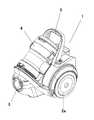
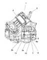
図1は、本実施の形態における掃除機本体の外観斜視図、図2は同掃除機本体の下後方
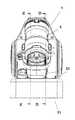
から見た外観斜視図、図3は同掃除機本体の後面図、図4は同掃除機本体の図3におけるA−A縦断面図である。1 is an external perspective view of the vacuum cleaner main body according to the present embodiment, FIG. 2 is an external perspective view of the vacuum cleaner main body viewed from the lower rear, FIG. 3 is a rear view of the vacuum cleaner main body, and FIG. It is AA longitudinal cross-sectional view in FIG. 3 of a main body.
本実施の形態における、掃除機本体1には、後部に電動送風機11と二次電池(図示せず)が内蔵され、前部に塵埃を分離捕集する集塵装置4が着脱自在に装着されている。掃除機本体1の後方両側に1対の走行用の車輪2aが回転自在に取着され、底面前部には、同じく走行用のキャスター2bが取着されている。掃除機本体1の前部には、ホース(図示せず)の一端に設けた接続パイプが着脱自在に接続される吸気口3が設けられて、ホースの他端には、延長管を介して床用吸込具(いずれも図示せず)が着脱自在に接続されている。掃除機本体1の上方には、持ち運び時に手持ち部となるハンドル5が配設され、掃除機本体1の後面には、電動送風機11からの排気を本体外に排出する排気口6が形成されている。 The vacuum cleaner
掃除機本体1の排気口6の下方位置に、後面から底面にわたって収納凹所7が形成されており、収納凹所7に略角筒状の本体端子収納部8が設けられている。本体端子収納部8の後端面には、本体端子10の収納部へ連通し、本体端子10を外部に臨ませる開口部8aが形成され、また、本体端子収納部8の近傍には、板状のシャッター開閉操作当接部9が設けられている。図4に示すように本体端子収納部8およびシャッター開閉操作当接部9は、収納凹所7より掃除機本体1の外面側に突出しないように配設して、本体端子収納部8およびシャッター開閉操作当接部9の床面などへの接触を防止している。 A
次に、充電台21について、図5〜8を用いて構成を説明する。 Next, the structure of the
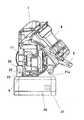
図5は、本実施の形態における充電台の外観斜視図、図6は同充電台の上面図、図7(a)は同充電台の図6におけるB−B縦断面図、図7(b)は同充電台のシャッター開閉操作部25の可動状態を示すB−B縦断面図、図8は同充電台の図6におけるC−C縦断面図である。 FIG. 5 is an external perspective view of the charging stand in the present embodiment, FIG. 6 is a top view of the charging stand, FIG. 7A is a vertical cross-sectional view of FIG. ) Is a BB longitudinal sectional view showing a movable state of the shutter opening /
図5において、充電台21は、上面に掃除機本体1を収納載置する載置部21aと、充電端子収納部22が設けられている。充電端子収納部22は、充電端子27を収納し、充電端子27に対向して充電端子27を外部に臨ませる充電端子開口部23を形成すると共に、充電端子開口部23内側を開閉自在に遮蔽するシャッター24を有している。充電端子収納部22は、充電端子開口部23に近接してシャッター開閉操作部25を充電端子収納部22外部に臨ませる開口22aを有している。シャッター開閉操作部25は、開口22aから充電端子収納部22の外殻面より突出しないように構成しており、落下物によって、あるいは人為的にシャッター開閉操作部25を操作できないようにしている。 In FIG. 5, the
図7(a)及び(b)は、シャッター開閉操作部25を示す充電台21の縦断面図である。シャッター開閉操作部25は、充電台21に掃除機本体1を載置すると、掃除機本体1のシャッター開閉操作当接部9が開口22aから挿入されることにより操作される。シャッター開閉操作当接部9とシャッター開閉操作部25によりシャッター24の開閉機構を構成している。 7A and 7B are longitudinal sectional views of the
シャッター開閉操作部25とシャッター24は、軸26によって連動するよう構成されており、図7(b)に示すように、シャッター開閉操作部25を回動させると、シャッター24も回動して充電端子開口部23が開口することになる。シャッター開閉操作部25およびシャッター24は、バネ(図示せず)によってシャッター24が充電端子開口部23を遮蔽する方向にバネ付勢して構成している。 The shutter opening /
続いて、掃除機本体1と充電台21について、図9〜13を用いて構成および動作を説
明する。Then, a structure and operation | movement are demonstrated about the
図9は、本実施の形態における掃除機本体の充電台載置状態を示す側面図、図10は同掃除機本体の充電台載置状態を示す掃除機本体の上面側から見た側面図、図11は同掃除機本体の充電台載置状態を示す図10におけるD−D縦断面図、図12は同掃除機本体の充電台載置状態を示す図10におけるE−E縦断面図、図13は同掃除機本体の本体端子と充電台の充電端子の接続直前の状態を示す要部断面図、図14は同掃除機本体の本体端子と充電台の充電端子の接続状態を示す要部断面図である。 FIG. 9 is a side view showing a charging stand mounting state of the cleaner main body in the present embodiment, FIG. 10 is a side view seen from the upper surface side of the cleaner main body showing the charging stand mounting state of the cleaner main body, FIG. 11 is a longitudinal sectional view taken on line DD in FIG. 10 showing the charging stand mounting state of the cleaner body, and FIG. 12 is an EE longitudinal sectional view showing the charging stand placement state of the cleaner body in FIG. FIG. 13 is a cross-sectional view of the main part showing a state immediately before the main body terminal of the vacuum cleaner body and the charging terminal of the charging stand are connected, and FIG. 14 is a main part showing the connection state of the main body terminal of the cleaner main body and the charging terminal of the charging stand. FIG.
図9および図10において、充電台21の載置部21aに掃除機本体1の後面を接地させるようにして収納載置させる。このとき、掃除機本体1が載置部21aに接近するにつれて、図11に矢示するように、掃除機本体1の後下面に設けたシャッター開閉操作当接部9が、シャッター開閉操作部25を軸26を中心に徐々に回動させる。図12に示すように、シャッター開閉操作部25と同軸で構成されているシャッター24も回動して充電端子開口部23が開口し、略角筒状の本体端子収納部8が充電端子収納部22の充電端子開口部23内に挿入される。 9 and 10, the mounting
本体端子収納部8とシャッター開閉操作当接部9は、シャッター開閉操作当接部9がシャッター開閉操作部25を操作してシャッター24を回動させ充電端子開口部23を開口させた状態で、本体端子収納部8が充電端子開口部23に挿入される長さと形状に設定している。 The main body
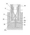
図13は、掃除機本体1の本体端子10と充電台21の充電端子27の接続直前の状態の本体端子収納部8と充電端子収納部22の拡大断面図、図14は、掃除機本体1の本体端子10と充電台21の充電端子27の接続状態の本体端子収納部8と充電端子収納部22の拡大断面図である。 FIG. 13 is an enlarged cross-sectional view of the main body
図13及び図14に示すように、充電台21の充電端子27は、充電端子収納部22の略中心位置に配設され、銅合金製で、先端側を略平板状に形成している。 As shown in FIGS. 13 and 14, the charging
本体端子収納部8は、充電端子収納部22よりも少許幅狭に形成されており、本体端子収納部8の開口部8aは、本体端子収納部8が充電端子収納部22の一側に偏って挿入された場合でも、充電端子27が挿入可能な大きさに形成されている。本体端子10は、銅合金製で、一対の端子部を有するクリップ状に形成されており、端子部間隔を狭めた充電端子27との接触部の下方を漸次広がる形状に形成している。 The main body
図13は、シャッター24が開いて充電端子開口部23を開口させ、略角筒状の本体端子収納部8が充電端子収納部22内に挿入され始めた状態を示している。 FIG. 13 shows a state in which the
本体端子収納部8の開口部8a側には、開口部8a内面側壁面との間に微小な隙間を設けて水平運動可能な一対のシャッターB32が配設されており、シャッターB32は、板バネ31の先端31aによりシャッターB32の相対向する先端部を当接させて開口部8aを閉じるようにバネ付勢している。シャッターB32の相対向する先端部分には、シャッターB32を開放する開放機構として、先端部分になるに従って外側から内側に傾斜する傾斜部32aが形成されており、傾斜部32aに充電端子27の先端が接触すると、図14に示すように、シャッターB32を傾斜部32aに沿わせて水平方向に移動させ、充電端子27が本体端子10の位置に到達し接続することとなる。シャッターB32は、充電端子27の挿入操作時に、シャッター押さえ30により本体端子収納部8内側への移動を阻止している。 On the side of the
本体端子10は、一対の端子部を有するクリップ状に形成し、端子部間隔を狭めた接触部の下方を漸次広がる形状に形成しているので、充電端子27と確実に電気的に接続でき、接触不良を低減できる。また、本体端子10は、一対の端子部を有しているので、充電端子27と2箇所で電気的に接続でき、接触不良をより低減できる。さらに、本体端子10は、一対の端子部を有しているので、本体端子収納部8が充電端子収納部22の一側に偏って挿入された場合でも、充電端子27が本体端子10の一方の端子部に電気的に接続し、二次電池への充電を可能とすることができる。 The
以上のように、充電端子27が本体端子収納部8の開口部8aから挿入されて充電台21の充電端子27と本体端子10が接続することとなる。 As described above, the charging
掃除機本体1を充電台21の載置部21aから取り外すと、シャッター開閉操作部25およびシャッター24は同軸でバネ(図示せず)によって充電端子開口部23を遮蔽する方向にバネ付勢して構成しているため、自動的に充電端子開口部23を遮蔽することができるものである。これら、前述の図11から図14に説明した動作は同時に行われるものである。 When the vacuum cleaner
これらにより、掃除使用中に掃除機本体1の底面側が床面に接触しても、本体端子10へのごみの付着を防止することができるので、電気的接触不良を発生させることがなく、また、電気的な安全性を確保することができるとともに、例えば二次電池の電圧を高く設定することによって、吸引力の向上や、掃除使用時間を延長することが可能となる。さらには、二次電池への給電電圧、電流設定を高くし、二次電池の満充電までの時間短縮を図ることが可能となる。またさらに、家屋内における落下物などにより、シャッター部に外力が加わった場合においてもシャッターが開状態となることを防止し、人為的にシャッターを開くような操作をすることをも防止することが可能で、安全性を確保することができるものである。 As a result, even if the bottom surface side of the vacuum cleaner
なお、上記実施の形態においては、本体端子収納部8を掃除機本体1後下部に配設したが、掃除機本体1の底面に配設してもよい。 In addition, in the said embodiment, although the main body
また、シャッターB32等を含む本体端子収納部8の構成を充電台21に採用し、シャッター24等を含む充電端子収納部22の構成を掃除機本体1に採用しても、前記同様の作用、効果を実現することが可能となる。 Further, even if the configuration of the main body
以上のように、本発明に係る充電式の電気掃除機は、充電端子部の接触不良を防止するとともに、充電端子周囲の安全性を確保することができるので、家庭用や業務用の電気掃除機等に適用できる。 As described above, the rechargeable vacuum cleaner according to the present invention can prevent poor contact of the charging terminal portion and can ensure safety around the charging terminal, so that the household or commercial vacuum cleaner can be used. Applicable to machine etc.
1 掃除機本体
4 集塵装置
8 本体端子収納部
8a 開口部
9 シャッター開閉操作当接部
10 本体端子
11 電動送風機
21 充電台
22 充電端子収納部
23 充電端子開口部
24 シャッター
25 シャッター開閉操作部
27 充電端子
30 シャッター押さえ
31 板バネ
32 シャッターBDESCRIPTION OF
Claims (3)
Translated fromJapanesePriority Applications (1)
| Application Number | Priority Date | Filing Date | Title |
|---|---|---|---|
| JP2013121512AJP2014236898A (en) | 2013-06-10 | 2013-06-10 | Vacuum cleaner |
Applications Claiming Priority (1)
| Application Number | Priority Date | Filing Date | Title |
|---|---|---|---|
| JP2013121512AJP2014236898A (en) | 2013-06-10 | 2013-06-10 | Vacuum cleaner |
Publications (1)
| Publication Number | Publication Date |
|---|---|
| JP2014236898Atrue JP2014236898A (en) | 2014-12-18 |
Family
ID=52134643
Family Applications (1)
| Application Number | Title | Priority Date | Filing Date |
|---|---|---|---|
| JP2013121512APendingJP2014236898A (en) | 2013-06-10 | 2013-06-10 | Vacuum cleaner |
Country Status (1)
| Country | Link |
|---|---|
| JP (1) | JP2014236898A (en) |
Cited By (5)
| Publication number | Priority date | Publication date | Assignee | Title |
|---|---|---|---|---|
| JP2016137165A (en)* | 2015-01-28 | 2016-08-04 | 日立アプライアンス株式会社 | Charging stand and vacuum cleaner |
| JP2020192427A (en)* | 2019-01-08 | 2020-12-03 | ビッセル インク. | Surface cleaning apparatus |
| CN112512394A (en)* | 2018-06-22 | 2021-03-16 | 必胜公司 | Surface cleaning apparatus and tray |
| US11825996B2 (en) | 2015-10-28 | 2023-11-28 | Bissell Inc. | Surface cleaning apparatus |
| US11963657B2 (en) | 2019-11-06 | 2024-04-23 | Bissell Inc. | Surface cleaning apparatus |
- 2013
- 2013-06-10JPJP2013121512Apatent/JP2014236898A/enactivePending
Cited By (14)
| Publication number | Priority date | Publication date | Assignee | Title |
|---|---|---|---|---|
| JP2016137165A (en)* | 2015-01-28 | 2016-08-04 | 日立アプライアンス株式会社 | Charging stand and vacuum cleaner |
| US11825996B2 (en) | 2015-10-28 | 2023-11-28 | Bissell Inc. | Surface cleaning apparatus |
| US12161273B2 (en) | 2015-10-28 | 2024-12-10 | Bissell Inc. | Surface cleaning apparatus |
| US11930975B2 (en) | 2015-10-28 | 2024-03-19 | Bissell Inc. | Surface cleaning apparatus |
| CN112842164A (en)* | 2018-06-22 | 2021-05-28 | 必胜公司 | Surface cleaning apparatus and cleaning system |
| CN112512394A (en)* | 2018-06-22 | 2021-03-16 | 必胜公司 | Surface cleaning apparatus and tray |
| US12213633B2 (en) | 2018-06-22 | 2025-02-04 | Bissell Inc. | Surface cleaning apparatus and tray |
| US11786097B1 (en) | 2019-01-08 | 2023-10-17 | Bissell Inc. | Surface cleaning apparatus |
| US11737629B2 (en) | 2019-01-08 | 2023-08-29 | Bissell Inc. | Surface cleaning apparatus |
| US11871892B1 (en) | 2019-01-08 | 2024-01-16 | Bissell Inc. | Surface cleaning apparatus |
| JP2020192427A (en)* | 2019-01-08 | 2020-12-03 | ビッセル インク. | Surface cleaning apparatus |
| US12193622B2 (en) | 2019-01-08 | 2025-01-14 | Bissell Inc. | Surface cleaning apparatus |
| US11963657B2 (en) | 2019-11-06 | 2024-04-23 | Bissell Inc. | Surface cleaning apparatus |
| US12232686B2 (en) | 2019-11-06 | 2025-02-25 | Bissell Inc. | Surface cleaning apparatus |
Similar Documents
| Publication | Publication Date | Title |
|---|---|---|
| JP2014236898A (en) | Vacuum cleaner | |
| CN205681594U (en) | A kind of earphone charger | |
| JP2015024124A (en) | Vacuum cleaner | |
| CN204813699U (en) | Brush for cleaner | |
| JP2015012946A (en) | Electric vacuum cleaner | |
| TWI708586B (en) | Electric vacuum cleaner | |
| JP2001353112A (en) | Electric vacuum cleaner | |
| TW202007346A (en) | Electric vacuum cleaner including a base portion, a standing portion and an extension member | |
| CN205107553U (en) | Wireless vertical type vacuum cleaner | |
| KR101544580B1 (en) | Protective Cap for Electric Charger | |
| JP2014236897A (en) | Vacuum cleaner | |
| CN112294178B (en) | Electric vacuum cleaner | |
| CN109195046B (en) | Earphone charging box | |
| CN112294182B (en) | electric vacuum cleaner | |
| CN110960142A (en) | Handheld dust collector with dust collection accessory storage structure | |
| CN115379785A (en) | Charging seat of electric dust collector | |
| CN210783236U (en) | Solar portable earphone bin | |
| CN210697474U (en) | a support frame | |
| JPH10257144A (en) | Charger for radio telephone set | |
| KR100394872B1 (en) | Electric vacuum cleaner | |
| CN208973670U (en) | A small-volume vacuum cleaner and a charging stand for power supply components | |
| CN114246506B (en) | Charging device and cleaning device | |
| CN216601680U (en) | Electronic smoking set capable of being positively or negatively charged and charging equipment | |
| JP2001050196A (en) | Blower | |
| JP2006095337A (en) | Electric vacuum cleaner |
Legal Events
| Date | Code | Title | Description |
|---|---|---|---|
| RD01 | Notification of change of attorney | Free format text:JAPANESE INTERMEDIATE CODE: A7421 Effective date:20141021 |