JP2014236757A - Guide wire - Google Patents
Guide wireDownload PDFInfo
- Publication number
- JP2014236757A JP2014236757AJP2011214697AJP2011214697AJP2014236757AJP 2014236757 AJP2014236757 AJP 2014236757AJP 2011214697 AJP2011214697 AJP 2011214697AJP 2011214697 AJP2011214697 AJP 2011214697AJP 2014236757 AJP2014236757 AJP 2014236757A
- Authority
- JP
- Japan
- Prior art keywords
- wire
- distal end
- coil
- guide wire
- tubular body
- Prior art date
- Legal status (The legal status is an assumption and is not a legal conclusion. Google has not performed a legal analysis and makes no representation as to the accuracy of the status listed.)
- Pending
Links
- 230000007246mechanismEffects0.000claimsabstractdescription50
- 230000000704physical effectEffects0.000claimsdescription7
- 238000003780insertionMethods0.000abstractdescription7
- 230000037431insertionEffects0.000abstractdescription7
- 238000000605extractionMethods0.000abstract1
- 238000010586diagramMethods0.000description16
- 230000009466transformationEffects0.000description13
- 210000004204blood vesselAnatomy0.000description11
- 229910045601alloyInorganic materials0.000description10
- 239000000956alloySubstances0.000description10
- 239000000463materialSubstances0.000description9
- BASFCYQUMIYNBI-UHFFFAOYSA-NplatinumChemical compound[Pt]BASFCYQUMIYNBI-UHFFFAOYSA-N0.000description8
- 229910001220stainless steelInorganic materials0.000description8
- 239000010935stainless steelSubstances0.000description8
- 238000005452bendingMethods0.000description6
- 229910000679solderInorganic materials0.000description6
- PCHJSUWPFVWCPO-UHFFFAOYSA-NgoldChemical compound[Au]PCHJSUWPFVWCPO-UHFFFAOYSA-N0.000description5
- 229910052737goldInorganic materials0.000description5
- 239000010931goldSubstances0.000description5
- 238000012423maintenanceMethods0.000description5
- 229910001000nickel titaniumInorganic materials0.000description5
- 239000003795chemical substances by applicationSubstances0.000description4
- KHYBPSFKEHXSLX-UHFFFAOYSA-NiminotitaniumChemical compound[Ti]=NKHYBPSFKEHXSLX-UHFFFAOYSA-N0.000description4
- 229910000510noble metalInorganic materials0.000description4
- 229910052697platinumInorganic materials0.000description4
- 229920005989resinPolymers0.000description4
- 239000011347resinSubstances0.000description4
- YCKRFDGAMUMZLT-UHFFFAOYSA-NFluorine atomChemical compound[F]YCKRFDGAMUMZLT-UHFFFAOYSA-N0.000description3
- 230000006835compressionEffects0.000description3
- 238000007906compressionMethods0.000description3
- 229910052731fluorineInorganic materials0.000description3
- 239000011737fluorineSubstances0.000description3
- 229920003023plasticPolymers0.000description3
- 239000004033plasticSubstances0.000description3
- 239000000126substanceSubstances0.000description3
- 229920003171Poly (ethylene oxide)Polymers0.000description2
- 229930182556PolyacetalNatural products0.000description2
- 239000004642PolyimideSubstances0.000description2
- 239000004372Polyvinyl alcoholSubstances0.000description2
- 230000015572biosynthetic processEffects0.000description2
- 239000000470constituentSubstances0.000description2
- 230000008531maintenance mechanismEffects0.000description2
- 229910052751metalInorganic materials0.000description2
- 239000002184metalSubstances0.000description2
- 239000007769metal materialSubstances0.000description2
- 230000000149penetrating effectEffects0.000description2
- XNGIFLGASWRNHJ-UHFFFAOYSA-Nphthalic acidChemical compoundOC(=O)C1=CC=CC=C1C(O)=OXNGIFLGASWRNHJ-UHFFFAOYSA-N0.000description2
- 229920002401polyacrylamidePolymers0.000description2
- 229920002647polyamidePolymers0.000description2
- 229920001721polyimidePolymers0.000description2
- 229920000642polymerPolymers0.000description2
- 239000002861polymer materialSubstances0.000description2
- 229920000098polyolefinPolymers0.000description2
- 229920006324polyoxymethylenePolymers0.000description2
- 229920002451polyvinyl alcoholPolymers0.000description2
- NIXOWILDQLNWCW-UHFFFAOYSA-MAcrylateChemical compound[O-]C(=O)C=CNIXOWILDQLNWCW-UHFFFAOYSA-M0.000description1
- PKAUISBSZACZJI-UHFFFAOYSA-NCC(=CC(=O)N)C.C(C(=C)C)(=O)OChemical compoundCC(=CC(=O)N)C.C(C(=C)C)(=O)OPKAUISBSZACZJI-UHFFFAOYSA-N0.000description1
- 229920000663Hydroxyethyl cellulosePolymers0.000description1
- 239000004354Hydroxyethyl celluloseSubstances0.000description1
- 229920002153Hydroxypropyl cellulosePolymers0.000description1
- 239000004677NylonSubstances0.000description1
- 239000004952PolyamideSubstances0.000description1
- 239000002202Polyethylene glycolSubstances0.000description1
- 229920002873PolyethyleniminePolymers0.000description1
- XBDQKXXYIPTUBI-UHFFFAOYSA-MPropionateChemical compoundCCC([O-])=OXBDQKXXYIPTUBI-UHFFFAOYSA-M0.000description1
- 229920002125Sokalan®Polymers0.000description1
- 238000002583angiographyMethods0.000description1
- 229920001400block copolymerPolymers0.000description1
- 229920003174cellulose-based polymerPolymers0.000description1
- 230000002490cerebral effectEffects0.000description1
- 239000002131composite materialSubstances0.000description1
- 229920001577copolymerPolymers0.000description1
- 125000004122cyclic groupChemical group0.000description1
- 229920000840ethylene tetrafluoroethylene copolymerPolymers0.000description1
- KNVWWMVPZMGMPG-UHFFFAOYSA-Nformaldehyde;3-methylbutan-2-oneChemical compoundO=C.CC(C)C(C)=OKNVWWMVPZMGMPG-UHFFFAOYSA-N0.000description1
- 235000019447hydroxyethyl celluloseNutrition0.000description1
- 239000001863hydroxypropyl celluloseSubstances0.000description1
- 235000010977hydroxypropyl celluloseNutrition0.000description1
- 230000000977initiatory effectEffects0.000description1
- 229920006276ketonic resinPolymers0.000description1
- FPYJFEHAWHCUMM-UHFFFAOYSA-Nmaleic anhydrideChemical compoundO=C1OC(=O)C=C1FPYJFEHAWHCUMM-UHFFFAOYSA-N0.000description1
- 238000000034methodMethods0.000description1
- 229920001778nylonPolymers0.000description1
- XNGIFLGASWRNHJ-UHFFFAOYSA-Lphthalate(2-)Chemical compound[O-]C(=O)C1=CC=CC=C1C([O-])=OXNGIFLGASWRNHJ-UHFFFAOYSA-L0.000description1
- 229920001495poly(sodium acrylate) polymerPolymers0.000description1
- 229920001467poly(styrenesulfonates)Polymers0.000description1
- 229920000728polyesterPolymers0.000description1
- 229920001223polyethylene glycolPolymers0.000description1
- 229920002338polyhydroxyethylmethacrylatePolymers0.000description1
- 229960002796polystyrene sulfonateDrugs0.000description1
- 239000011970polystyrene sulfonateSubstances0.000description1
- 239000004810polytetrafluoroethyleneSubstances0.000description1
- 229920001343polytetrafluoroethylenePolymers0.000description1
- 229920000036polyvinylpyrrolidonePolymers0.000description1
- 239000001267polyvinylpyrrolidoneSubstances0.000description1
- 235000013855polyvinylpyrrolidoneNutrition0.000description1
- 230000000717retained effectEffects0.000description1
- 238000005096rolling processMethods0.000description1
- 229920002545silicone oilPolymers0.000description1
- NNMHYFLPFNGQFZ-UHFFFAOYSA-Msodium polyacrylateChemical compound[Na+].[O-]C(=O)C=CNNMHYFLPFNGQFZ-UHFFFAOYSA-M0.000description1
- 238000005476solderingMethods0.000description1
- 229920003169water-soluble polymerPolymers0.000description1
- 238000004804windingMethods0.000description1
Images


Classifications
- A—HUMAN NECESSITIES
- A61—MEDICAL OR VETERINARY SCIENCE; HYGIENE
- A61M—DEVICES FOR INTRODUCING MEDIA INTO, OR ONTO, THE BODY; DEVICES FOR TRANSDUCING BODY MEDIA OR FOR TAKING MEDIA FROM THE BODY; DEVICES FOR PRODUCING OR ENDING SLEEP OR STUPOR
- A61M25/00—Catheters; Hollow probes
- A61M25/01—Introducing, guiding, advancing, emplacing or holding catheters
- A61M25/09—Guide wires
- A61M2025/09058—Basic structures of guide wires
- A61M2025/09083—Basic structures of guide wires having a coil around a core
- A—HUMAN NECESSITIES
- A61—MEDICAL OR VETERINARY SCIENCE; HYGIENE
- A61M—DEVICES FOR INTRODUCING MEDIA INTO, OR ONTO, THE BODY; DEVICES FOR TRANSDUCING BODY MEDIA OR FOR TAKING MEDIA FROM THE BODY; DEVICES FOR PRODUCING OR ENDING SLEEP OR STUPOR
- A61M25/00—Catheters; Hollow probes
- A61M25/01—Introducing, guiding, advancing, emplacing or holding catheters
- A61M25/09—Guide wires
- A61M2025/09175—Guide wires having specific characteristics at the distal tip
Landscapes
- Health & Medical Sciences (AREA)
- Life Sciences & Earth Sciences (AREA)
- Biophysics (AREA)
- Pulmonology (AREA)
- Engineering & Computer Science (AREA)
- Anesthesiology (AREA)
- Biomedical Technology (AREA)
- Heart & Thoracic Surgery (AREA)
- Hematology (AREA)
- Animal Behavior & Ethology (AREA)
- General Health & Medical Sciences (AREA)
- Public Health (AREA)
- Veterinary Medicine (AREA)
- Media Introduction/Drainage Providing Device (AREA)
Abstract
Description
Translated fromJapanese本発明は、ガイドワイヤに関するものである。特に、脳血管などの細径の血管内にカテーテルを導入する際に用いられるガイドワイヤに関する。 The present invention relates to a guide wire. In particular, the present invention relates to a guide wire used when a catheter is introduced into a small blood vessel such as a cerebral blood vessel.
ガイドワイヤは、外科的手術が困難な部位の治療、または人体への低侵襲を目的とした治療、管造影などの検査に用いられるカテーテルを誘導するのに使用される。血管は、複雑に湾曲しており、ガイドワイヤの先端部分は、選択目的血管を考慮して、目的血管への挿入を容易なものとするために、一方向に湾曲した形状に予め形づけられているものがある。
しかしながら、ガイドワイヤの先端部分の湾曲方向が血管の形状に沿うように血管の立体形状を想像しながらガイドワイヤを挿入する操作は容易ではない。また、予め付与された形状では、挿入が良好に行えない場合もあり、その場合には、ガイドワイヤを血管より抜去し、先端部を別形状に形状付けした後、再度血管内に挿入するといった手技が必要となる。The guide wire is used to guide a catheter used for treatment of a site where surgical operation is difficult, treatment for the purpose of minimally invasive to the human body, and examination such as angiography. The blood vessel is intricately curved, and the distal end portion of the guide wire is pre-shaped into a curved shape in one direction in order to facilitate insertion into the target blood vessel in consideration of the selected target blood vessel. There is something that is.
However, it is not easy to insert the guide wire while imagining the three-dimensional shape of the blood vessel so that the bending direction of the distal end portion of the guide wire follows the shape of the blood vessel. In addition, the shape given in advance may not be able to be inserted satisfactorily. In that case, the guide wire is removed from the blood vessel, the tip is shaped into another shape, and then inserted into the blood vessel again. A procedure is required.
最近では、特開2010−207251(特許文献1)のようなガイドワイヤの先端形状を手元操作により変形可能なガイドワイヤが提案されている。
特許文献1のガイドワイヤは、可撓性を有する筒状のチューブ2と、該チューブ2内に長手方向に沿って移動可能に挿入され、その先端部分をチューブ2の先端から突出させた可撓性を有するワイヤ3と、該ワイヤ3の先端とチューブ2の先端とに両端が固定された弾性部材4とを備え、該弾性部材4が、チューブ2の長手方向に沿って略直線形状に収縮し、チューブ2と略同等またはそれより低い可撓性を有する収縮状態と、先端をチューブ2の長手方向に対して所定の方向に向けて湾曲しながら延伸し、チューブ2より高い可撓性を有する延伸状態との間で弾性変形可能であり、ワイヤ3が、少なくとも先端部分において延伸状態の弾性部材4より高い可撓性を有するものとなっている。
また、特許文献1には、チューブ2とワイヤワイヤ3の長手方向の位置を固定する固定機構、例えば、互いに噛み合うネジやラチェットがそれぞれの基端側に設けられていてもよいとの開示がある。Recently, there has been proposed a guide wire that can deform the tip shape of the guide wire by hand operation as disclosed in JP 2010-207251 (Patent Document 1).
The guide wire of
Further,
特許文献1のものでも有効性はあるが、特許文献1のものでは、ワイヤ3の基端部に設けられているハンドル5は、チューブ2より、大径となっており、カテーテルのガイドワイヤ挿通孔に、ハンドル側から挿入することができず、使用できるカテーテルのタイプが限定されるものであった。また、上述のように、チューブ2とワイヤ3の長手方向の位置を固定する固定機構を設けてもよい旨の記載はあるが、具体的に示されているのは、図2に示されるハンドル5の挿入部分5aにネジ山5cが、チューブ2の基端側の内面にネジ溝5dが設けられているタイプのもののみである。ガイドワイヤの基端に設けられた小さなハンドルの回転操作を手術用手袋を装着した状態で行うことは、容易なものではなく、ハンドルの回動により徐々に変形するため、レスポンスも悪い。
そこで、本発明の目的は、手元での操作により、先端部の形状を変形可能なガイドワイヤにおいて、カテーテルのガイドワイヤ挿通孔に、ガイドワイヤの先端側のみならず基端側からの挿入が可能であり、さらに、手元の操作部を回動することなく牽引することにより、ガイドワイヤの先端部を容易かつ迅速に変形可能であり、かつ、牽引によるガイドワイヤの変形状態の確保およびその解除も容易であり、操作性が良好なガイドワイヤを提供するものである。Although the thing of
Accordingly, an object of the present invention is to allow a guide wire whose shape of the distal end portion can be deformed by hand operation, and can be inserted not only from the distal end side of the guide wire but also from the proximal end side into the guide wire insertion hole of the catheter. Furthermore, the tip of the guide wire can be easily and quickly deformed by towing the operating portion without being turned, and the guide wire can be deformed and released by towing. A guide wire that is easy and has good operability is provided.
上記目的を達成するものは、以下のものである。
(1) 管状体と、該管状体内を摺動可能に挿通するワイヤと、前記ワイヤの先端側部分を被包するコイル部と、前記ワイヤの前記管状体より露出する基端部に設けられたワイヤ操作部とを備えるガイドワイヤであって、
前記ワイヤ操作部の最大径部分は、前記管状体の外径と同等もしくはそれより小さく、前記コイル部は、直線状または湾曲形状もしくは湾曲形状に形状付け可能であり、かつ、前記コイル部に被包された前記ガイドワイヤの先端部は、前記ワイヤの基端方向への牽引により、前記直線状から湾曲形状へもしくは前記湾曲形状からほぼ直線状に変形可能であり、さらに、前記ワイヤおよび前記管状体は、前記ワイヤ操作部の軸方向への操作により、前記先端部の変形および変形を保持するためのガイドワイヤ先端部変形状態保持機構を備えているガイドワイヤ。What achieves the above object is as follows.
(1) Provided in a tubular body, a wire that is slidably inserted through the tubular body, a coil portion that encloses a distal end portion of the wire, and a proximal end portion that is exposed from the tubular body of the wire. A guide wire including a wire operation unit,
The maximum diameter portion of the wire operation portion is equal to or smaller than the outer diameter of the tubular body, the coil portion can be formed into a linear shape, a curved shape, or a curved shape, and the coil portion is covered with the coil portion. The distal end portion of the wrapped guide wire can be deformed from the linear shape to the curved shape or from the curved shape to a substantially linear shape by pulling in the proximal direction of the wire, and further, the wire and the tubular shape The body is provided with a guide wire tip portion deformation state holding mechanism for holding deformation and deformation of the tip portion by an operation of the wire operation portion in the axial direction.
(2) 前記ガイドワイヤ先端部変形状態保持機構は、前記ワイヤの前記ワイヤ操作部より先端側となる部位に設けられたワイヤ側形態保持部と、前記管状体に設けられた管状体側形態保持部とを備え、前記ワイヤ側形態保持部と前記管状体側形態保持部との係合もしくは圧接により、前記ワイヤ先端部の変形形態を保持するものである上記(1)に記載のガイドワイヤ。
(3) 前記ワイヤ側形態保持部と前記管状体側形態保持部は、前記ワイヤを回転させることなく、係合もしくは圧接するものである上記(2)に記載のガイドワイヤ。
(4) 前記コイル部は、直線状であり、前記コイル部に被包された前記ガイドワイヤの先端部は、前記ワイヤの基端方向への牽引により、前記直線状から湾曲形状に変形するものである上記(1)ないし(3)のいずれかに記載のガイドワイヤ。
(5) 前記ワイヤは、前記ワイヤ操作部より先端側となる部位に軸方向に設けられた変形部を備え、前記管状体の内面は、前記変形部と摺動可能に圧接するものとなっており、前記ガイドワイヤ先端部変形状態保持機構は、前記変形部と前記管状体の基端部内面により構成されている上記(1)ないし(4)のいずれかに記載のガイドワイヤ。
(6) 前記ガイドワイヤ先端部変形状態保持機構は、前記ワイヤの前記ワイヤ操作部より先端側となる部位に設けられた変形部と、前記管状体の基端部内面に設けられた前記変形部と係合可能な凹部もしくは突出部とにより構成されている上記(1)ないし(4)のいずれかに記載のガイドワイヤ。
(7) 前記ガイドワイヤ先端部変形状態保持機構は、前記ワイヤの前記ワイヤ操作部より先端側となる部位に軸方向に複数設けられた変形部と、前記変形部と係合可能な前記管状体の基端開口部とにより構成されている上記(1)ないし(4)のいずれか記載のガイドワイヤ。
(8) 前記ガイドワイヤ先端部変形状態保持機構は、前記ワイヤの前記ワイヤ操作部より先端側となる部位に設けられた軸方向に延びる突出部と、前記管状体の基端部内面に設けられ、前記ワイヤの前記突出部が圧接状態にて摺動可能な内面部とにより構成されている上記(1)ないし(4)のいずれか記載のガイドワイヤ。
(9) 前記ガイドワイヤ先端部変形状態保持機構は、前記ワイヤの前記ワイヤ操作部より先端側となる部位に設けられた軸方向に延びる複数のリブと、前記管状体の基端部内面に設けられ、前記ワイヤの前記リブを収納可能な軸方向に延びる溝部とにより構成されており、さらに、前記ワイヤを牽引し、前記リブが、前記管状体に基端開口より露出した状態にて、前記ワイヤ操作部を若干回転させることにより、前記リブは、前記管状体の基端面と当接し係合するものとなっている上記(1)ないし(4)のいずれか記載のガイドワイヤ。
(10) 前記ワイヤは、前記ワイヤ操作部より先端側に設けられ、前記ワイヤの外面と圧接した状態にて前記ワイヤの先端方向および基端方向にスライド可能かつ、前記管状体の基端部と当接可能なスライド部材を備え、前記ガイドワイヤ先端部変形状態保持機構は、前記スライド部材と前記管状体の基端部とにより構成されている上記(1)ないし(4)のいずれか記載のガイドワイヤ。(2) The guide wire tip portion deformed state holding mechanism includes a wire side shape holding portion provided in a portion of the wire that is on the tip side from the wire operation portion, and a tubular body side shape holding portion provided in the tubular body. The guide wire according to (1), wherein the deformed form of the wire tip end part is held by engagement or pressure contact between the wire side form holding part and the tubular body side form holding part.
(3) The guide wire according to (2), wherein the wire side shape holding portion and the tubular body side shape holding portion are engaged with or pressed against each other without rotating the wire.
(4) The coil portion is linear, and the distal end portion of the guide wire encapsulated in the coil portion is deformed from the linear shape to a curved shape by pulling in the proximal direction of the wire. The guide wire according to any one of (1) to (3) above.
(5) The wire includes a deformed portion provided in an axial direction at a portion closer to the distal end than the wire operation portion, and an inner surface of the tubular body is slidably pressed against the deformed portion. The guide wire distal portion deformed state holding mechanism is the guide wire according to any one of the above (1) to (4), which is configured by the deformed portion and the inner surface of the proximal end portion of the tubular body.
(6) The guide wire distal end portion deformed state holding mechanism includes a deformed portion provided at a position closer to the distal end side than the wire operation portion of the wire, and the deformed portion provided on the inner surface of the proximal end portion of the tubular body. The guide wire according to any one of (1) to (4), wherein the guide wire is configured by a concave portion or a protruding portion that can be engaged with each other.
(7) The guide wire distal end portion deformed state holding mechanism includes a plurality of deformed portions provided in the axial direction at a portion on the distal end side of the wire operation portion of the wire, and the tubular body engageable with the deformed portion. The guide wire as set forth in any one of (1) to (4), wherein the guide wire is configured by a base end opening.
(8) The guide wire distal end portion deformed state holding mechanism is provided on a protruding portion extending in the axial direction provided at a portion of the wire on the distal end side from the wire operation portion, and on an inner surface of the proximal end portion of the tubular body. The guide wire according to any one of (1) to (4), wherein the protruding portion of the wire is configured by an inner surface portion that is slidable in a pressure contact state.
(9) The guide wire distal end portion deformed state holding mechanism is provided on the inner surface of the proximal end portion of the tubular body, and a plurality of ribs extending in the axial direction provided at a portion on the distal end side of the wire operation portion of the wire. And an axially extending groove that can accommodate the rib of the wire, and further pulling the wire, the rib being exposed from the proximal end opening in the tubular body, The guide wire according to any one of (1) to (4), wherein the rib is brought into contact with and engaged with the proximal end surface of the tubular body by slightly rotating the wire operation portion.
(10) The wire is provided on the distal end side with respect to the wire operation portion, is slidable in the distal direction and the proximal direction of the wire in a state of being pressed against the outer surface of the wire, and the proximal end portion of the tubular body The guide wire tip portion deformed state holding mechanism is provided with an abuttable slide member, and is configured by the slide member and a base end portion of the tubular body, according to any one of the above (1) to (4). Guide wire.
(11) 前記コイル部は、略半球状のコイル部先端部と、前記コイル部先端部に先端が固定されたコイル体とを備えている上記(1)ないし(10)のいずれかに記載のガイドワイヤ。
(12) 前記コイル部は、前記コイル部先端部より基端側部分に設けられたワイヤ先端部固定部材を備え、前記ワイヤの先端が、前記ワイヤ先端部固定部材に固定されており、前記コイル部は、前記ワイヤの牽引による影響を受けない先端側コイル部を備えている上記(11)に記載のガイドワイヤ。
(13) 前記コイル部は、前記ワイヤ先端部固定部材に先端が固定された本体側コイル部材と、前記コイル部先端部に先端が固定され、基端が前記ワイヤ先端部固定部材に固定され、前記本体側コイル部材と物性が異なる先端側コイル部材とを備えている上記(12)に記載のガイドワイヤ。
(14) 前記コイル部は、略半球状のコイル部先端部と、前記コイル部先端部に先端が固定されたコイル体と、前記コイル体の基端に固定され、前記ワイヤが貫通するリング状部材とを備え、かつ、前記リング状部材は、前記管状体に固定されておらず、さらに、前記ワイヤは、前記リング状部材を貫通するとともに、前記ワイヤに付与した回転力を前記リング状部材に伝達するコイル部への回動トルク付与部材を備えている上記(1)ないし(13)のいずれかに記載のガイドワイヤ。(11) The coil unit according to any one of (1) to (10), wherein the coil unit includes a substantially hemispherical coil portion tip and a coil body having a tip fixed to the coil portion tip. Guide wire.
(12) The coil portion includes a wire distal end fixing member provided at a proximal end portion with respect to the coil portion distal end, and the distal end of the wire is fixed to the wire distal end fixing member. The guide wire according to (11), wherein the portion includes a distal coil portion that is not affected by the pulling of the wire.
(13) The coil portion includes a body side coil member having a distal end fixed to the wire distal end fixing member, a distal end fixed to the coil portion distal end, and a proximal end fixed to the wire distal end fixing member. The guide wire according to (12), further including a distal end side coil member having different physical properties from the main body side coil member.
(14) The coil portion includes a substantially hemispherical coil portion distal end portion, a coil body having a distal end fixed to the coil portion distal end portion, a ring shape that is fixed to the proximal end of the coil body and penetrates the wire. And the ring-shaped member is not fixed to the tubular body. Further, the wire penetrates the ring-shaped member, and a rotational force applied to the wire is applied to the ring-shaped member. The guide wire according to any one of (1) to (13), further including a rotation torque applying member to the coil portion that transmits to the coil.
本発明のガイドワイヤは、管状体と、管状体内を摺動可能に挿通するワイヤと、ワイヤの先端側部分を被包するコイル部と、ワイヤの管状体より露出する基端部に設けられたワイヤ操作部とを備える。ワイヤ操作部の最大径部分は、管状体の外径と同等もしくはそれより小さく、コイル部は、直線状または湾曲形状もしくは湾曲形状に形状付け可能であり、かつ、コイル部に被包されたガイドワイヤの先端部は、ワイヤの基端方向への牽引により、直線状から湾曲形状へもしくは湾曲形状からほぼ直線状に変形可能であり、さらに、ワイヤおよび管状体は、ワイヤ操作部の軸方向への操作により、先端部の変形および変形を保持するためのガイドワイヤ先端部変形状態保持機構を備えている。
このため、ガイドワイヤは、ワイヤ操作部側より、カテーテルのガイドワイヤ挿通孔に挿入可能である。さらに、ワイヤおよび管状体は、ワイヤ操作部を軸方向に操作することにより、ガイドワイヤの先端部を変形可能であり、かつ、ガイドワイヤの先端部の変形状態の保持が可能となっている。特に、ワイヤ操作部を回動することなく牽引することにより、ガイドワイヤの先端部を容易かつ迅速に変形可能であり、ガイドワイヤ先端部変形状態保持機構により、ガイドワイヤの変形状態の確保およびその解除も容易である。このためガイドワイヤは、良好な操作性を有する。The guide wire of the present invention is provided in a tubular body, a wire that is slidably inserted in the tubular body, a coil portion that encloses a distal end portion of the wire, and a proximal end portion that is exposed from the tubular body of the wire. A wire operation unit. The maximum diameter portion of the wire operation portion is equal to or smaller than the outer diameter of the tubular body, and the coil portion can be formed into a linear shape, a curved shape, or a curved shape, and the guide encapsulated in the coil portion. The distal end portion of the wire can be deformed from a straight shape to a curved shape or from a curved shape to a substantially linear shape by pulling in the proximal direction of the wire, and the wire and the tubular body can be moved in the axial direction of the wire operation portion. The guide wire tip portion deformed state holding mechanism for holding the tip portion deformed and deformed by the above operation is provided.
For this reason, the guide wire can be inserted into the guide wire insertion hole of the catheter from the wire operation unit side. Furthermore, the wire and the tubular body can deform the distal end portion of the guide wire by operating the wire operation portion in the axial direction, and can hold the deformed state of the distal end portion of the guide wire. In particular, the tip of the guide wire can be easily and quickly deformed by pulling the wire operating portion without rotating, and the guide wire tip portion deformed state holding mechanism can secure the deformed state of the guide wire and Release is also easy. For this reason, the guide wire has good operability.
本発明のガイドワイヤを図面に示す実施例を用いて説明する。
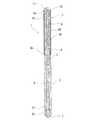
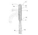
本発明のガイドワイヤ1は、管状体2と、管状体2内を摺動可能に挿通するワイヤ4と、ワイヤ4の先端側部分を被包するコイル部3と、ワイヤ4の管状体2より露出する基端部に設けられたワイヤ操作部7とを備える。ワイヤ操作部7の最大径部分は、管状体2の外径と同等もしくはそれより小さく、コイル部3は、直線状または湾曲形状もしくは湾曲形状に形状付け可能であり、かつ、コイル部3に被包されたガイドワイヤ4の先端部は、ワイヤ4の基端方向への牽引により、直線状から湾曲形状へもしくは湾曲形状からほぼ直線状に変形可能であり、さらに、ワイヤ4および管状体2は、ワイヤ操作部7の軸方向への操作により、先端部の変形および変形を保持するためのガイドワイヤ先端部変形状態保持機構を備えている。The guide wire of the present invention will be described using an embodiment shown in the drawings.
The
この実施例のガイドワイヤ1は、管状体2、管状体内を摺動可能に挿通するワイヤ4、ワイヤ4の先端側部分を被包するコイル部3とを備える。
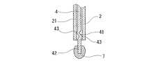
さらに、この実施例のガイドワイヤ1では、図1ないし図3に示すように、ガイドワイヤ先端部変形状態保持機構は、ワイヤ4のワイヤ操作部7より先端側となる部位に設けられたワイヤ側形態保持部41と、管状体2に設けられた管状体側形態保持部とを備え、ワイヤ側形態保持部と管状体側形態保持部との圧接により、ワイヤ先端部の変形形態を保持するものとなっている。そして、この実施例のガイドワイヤ1では、ワイヤ側形態保持部41と管状体側形態保持部は、ワイヤ4を回転させることなく、圧接するものとなっている。さらには、ワイヤ4は、ワイヤ操作部7より先端側となる部位に軸方向に設けられた変形部(ワイヤ側形態保持部)41を備え、管状体2の内面21(管状体側形態保持部を構成する)は、変形部41と摺動可能に圧接するものとなっており、ガイドワイヤ先端部変形状態保持機構は、変形部41と管状体2の基端部内面21により構成されている。さらに、この実施例のガイドワイヤ1では、コイル部3は、直線状であり、コイル部3に被包されたガイドワイヤの先端部は、ワイヤ4の基端方向への牽引により、直線状から湾曲形状に変形するものとなっている。The
Furthermore, in the
この実施例のガイドワイヤ1では、管状体2は、先端から基端まで貫通したある程度の可撓性を有する中空体である。管状体2は、カテーテル素材であるポリオレフィン系、ポリアミド系、ポリアセタール系、ポリイミド系、フッ素系等の樹脂チューブ、ステンレス鋼(SUS304,SUS316等)等の金属チューブ、NiTi系合金等の超弾性金属チューブ、また、樹脂とステンレス鋼(SUS304,SUS316等)等のワイヤをコイル巻き或いはブレード巻きした複合チューブなどの可撓性管状体が好適に使用される。管状体2の外径は、0.17〜0.97mmであることが好ましく、特に、0.30〜0.46mmが好ましい。管状体2の肉厚は、35〜150μmが好ましい。また、管状体2の長さは、290〜4490mmが好ましい。 In the
ワイヤ4は、上述した管状体2内を摺動可能に挿通しており、かつ、管状体2の先端より、先端部が、基端より基端部が突出している。
ワイヤ4の構成材料としては、例えば、Ni−Ti合金等の超弾性合金、ステンレス鋼、ピアノ線等の各種金属材料などが用いられる。ワイヤ4としては、全長が300mm〜4500mm、好ましくは1000mm〜2000mmであり、ワイヤ4の外径としては、直径0.10〜0.60mm、好ましくは、0.15〜0.25mmである。また、ワイヤ4としては、先端部が基端部より柔軟なものであってもよい。The
As a constituent material of the
そして、 ワイヤ4は、管状体2より露出する基端部42に設けられたワイヤ操作部7を備える。この実施例では、ワイヤ操作部7は、ワイヤ4の基端部42に操作部材を固定することにより形成されている。なお、ワイヤ操作部7は、ワイヤ4の基端部を大径なものとすることにより形成してもよい。そして、本発明のガイドワイヤでは、ワイヤ操作部7の最大径部分は、管状体2の外径より小さいものとなっており、ガイドワイヤが使用されるカテーテルのガイドワイヤ挿通孔に、ワイヤ操作部側、言い換えれば、ガイドワイヤの基端側からの挿入が可能となっている。
ワイヤ4の先端側部分には、ワイヤ4の先端部を被包するとともに、先端部6aにてワイヤ4の先端部と固定されたコイル部3を備えている。The
The distal end portion of the
特に、この実施例のガイドワイヤ1では、コイル部3は、略半球状のコイル部先端部11と、コイル部先端部11に先端6aが固定されたコイル体6と、コイル体6の基端6bを備えている。そして、コイル体6は、その内面が、実質的にワイヤ4の外面に接触しないものとなっている。このため、ワイヤ牽引時における、ワイヤとコイル体が摺接することがなく、ワイヤの牽引およびコイル体の変形を確実なものとしている。
コイル部3としては、全長が10mm〜500mm、好ましくは20mm〜300mmであり、コイル部3の外径としては、直径0.17〜0.97mm、好ましくは、0.30〜0.46mmである。また、コイル部3は、図1ないし図3に示すように、ワイヤが牽引されない状態では、その全長において、直線上のものとなっている。In particular, in the
The
コイル体6は、例えば、Ni−Ti合金等の超弾性合金、ステンレス鋼、金、白金などの貴金属などの線材により形成されたものが好適である。そして、コイル体6の先端は、ワイヤ4の先端に形成された略半球状のコイル部先端部11により固定されている。コイル部先端部11は、例えば、ロウにより形成される。そして、略半球状とは、実質的に曲面に成形されていることを意味し、例えば釣鐘状、弾丸状などの形状を含むものである。また、ワイヤ4の先端45は、コイル部先端部11に固定されている。このため、ワイヤ4を牽引することにより、コイル部先端部11が基端側に牽引される。 The
さらに、この実施例のガイドワイヤ1では、図2および図3に示すように、先端に向かって可撓性(言い換えれば、柔軟性)が高いものとなっている。特に、この実施例では、ワイヤ4の先端部は、先端側に向かって縮径するテーパー部46と、テーパー部46の先端側に設けられた薄板部47を備えている。そして、薄板部47の先端部が、コイル部先端部11に固定されている。
ワイヤ4の先端部の形状を上記のようにすることにより、先端部を柔軟なものとすることができるとともに、物性の変化もなだらかなものとなり、キンク等の発生を防止でき、かつ、良好に変形し、操作性も向上する。
そして、薄板部47は、ワイヤ4の先端部を押しつぶす(圧延すること)ことにより形成されている。このため、薄板部47の厚さは、テーパー部46の先端の外径より薄く、かつ、幅は、テーパー部46の先端の外径より広くなっている。このように、ワイヤ4の先端を平板状とすることにより、ワイヤ4の先端はより柔軟なものとなる。Furthermore, in the
By making the shape of the tip end portion of the
The
さらに、この実施例では、ワイヤ4は、上述したテーパー部46と薄板部47間の境界部(言い換えれば、薄板部47の基端部)48が、ワイヤ牽引時における易屈曲点を形成する。また、薄板部47により変形方向が規制される。ワイヤ4は、境界部48部分において、物性が変化するため、ワイヤ4を牽引したとき、境界部48部分にて、湾曲が発生し易く、言い換えれば、確実に湾曲し、かつその方向は、薄板部47の表側もしくは裏側となる。薄板部47の側部方向への湾曲が生じる可能性は極めて低い。そして、薄板部47が湾曲することにより、薄板部47部分を被包する部分のコイル部3も湾曲し、図1に破線に示すように、ガイドワイヤ1の先端部は、変形する。さらに、ワイヤ4の牽引を進めると、薄板部47を被包する部分のコイル部3の変形に引っ張られるように、ワイヤ4のテーパー部46およびそれを被包する部分のコイル部3も湾曲する。 Further, in this embodiment, in the
また、ワイヤ4のテーパー部46の長さは、50〜400mmであり、好ましくは、80〜300mmである。また、ワイヤ4のテーパー部46の最小外径は、40〜300μmであり、好ましくは、50〜250μmである。そして、薄板部47の長さは、5〜50mmであり、好ましくは、10〜30mmであり、厚さは、10〜100μmであり、好ましくは、20〜60μmであり、幅は、0.03〜0.3mmであり、好ましくは、0.05〜0.2mmである。
また、この実施例のガイドワイヤ1では、コイル体6の基端部は、管状体2の縮径する先端部を被覆し、両者は、固着剤8により固定されたもとなっている。コイル体6が管状体2に固定されているため、コイル体6と管状体2間が離間することがない。固定は、ハンダ付により行うことが好ましく、固着剤8であるハンダとしては、銀ろうまたは金ろうなどの硬ろうが好適に使用できる。Moreover, the length of the
Further, in the
このガイドワイヤ1では、図1ないし図3に示すように、ワイヤ4は、ワイヤ操作部7より先端側となる部位に設けられた変形部41を備えている。変形部41が、ワイヤ側形態保持部を形成している。そして、変形部41は、軸方向に近接しかつ若干離間するように設けられた複数の屈曲部(突出部)43を備えている。また、管状体2の基端部内面21は、変形部41と摺動可能に圧接するものとなっており、管状体側形態保持部を構成している。
具体的には、ワイヤ4の操作部7より所定長先端側となる部分は、ジグザグ状に変形した変形部41となっており、変形部41は、管状体2の内面方向を向いた頂点を有する複数の屈曲部43を備えている。また、管状体2の基端部内面21は、変形部41の少なくとも2つの頂点43が同時に圧接(摺接)することにより、ワイヤ4の管状体2の軸方向への移動時に摺動抵抗を生じさせる。このため、ワイヤ4は、管状体2との摺動抵抗以上の力を持って基端側に牽引もしくは先端側に押し込むことにより、図1の矢印方向に、操作部7は移動し、図4に示すような状態となり、操作部7は、管状体2の基端より離間する。また、ワイヤ4は、管状体2との摺動抵抗以上の力を持って基端側に牽引もしくは先端側に押し込まない限り、その状態(その位置およびガイドワイヤの先端部の形態)を維持するものとなっている。そして、ワイヤ4の牽引量(牽引長)を調整することにより、ガイドワイヤの先端部の変形状態、言い換えれば、ガイドワイヤの先端部の湾曲変形の程度を選択することができ、また、元の形状(直線形状)への復元もしくは直線形状に近づく方向への変形を可能としている。In this
Specifically, the portion of the
そして、上述したガイドワイヤ1では、変形部(ワイヤ側形態保持部)41と管状体2の内面21(管状体側形態保持部を構成する)は、任意の位置にて両者間の摩擦力によりその位置を保持するため、ガイドワイヤの先端部の変形の程度は、段階的なものではなく、任意なものとすることができ、微妙な先端部の操作を可能としている。このことにより、術者が術中に先端部の所望形状を作ることが出来るので、通常は選択困難な分岐血管へ比較的容易に選択挿入することが可能となる。
また、変形部41の形成位置は、ワイヤ4の基端より所定長先端側に位置し、図4に示すように、ワイヤ4の牽引操作を行っても(言い換えれば、牽引最大可能量牽引しても)、変形部41が、管状体2の基端部より露出しないものとなっており、露出した変形部に起因するキンクを防止する。And in the
Further, the position where the
なお、本発明のガイドワイヤにおけるガイドワイヤ先端部変形状態保持機構は、上述したものに限定されるものではない。
ガイドワイヤ先端部変形状態保持機構としては、例えば、図5および図6に示すガイドワイヤ1aが備えるタイプのものであってもよい。図5は、本発明のガイドワイヤの他の実施例の基端部の構造を説明するための説明図である。図6は、図5に示したガイドワイヤの作用を説明するための説明図である。
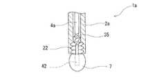
この実施例のガイドワイヤ1aでは、ワイヤ4aおよび管状体2aは、ワイヤ操作部7を基端方向に牽引することにより係合し、コイル部3の圧縮状態の保持およびワイヤ操作部7を操作することにより圧縮保持状態の解除が可能な係合機構(ガイドワイヤ先端部変形状態保持機構)を備えている。この実施例のものでは、保持機構(係合機構)は、ワイヤ操作部7を基端方向に牽引しない状態では、係合せず、牽引することにより、係合するものとなっている。Note that the guide wire tip portion deformed state holding mechanism in the guide wire of the present invention is not limited to the above-described one.
As a guide wire front-end | tip part deformation | transformation state holding mechanism, the thing of the type with which the
In the
図5および図6に示すものでは、ワイヤ4aと管状体2aとの係合機構は、ワイヤ4aのワイヤ操作部7より先端側となる部位に軸方向に複数設けられた変形部と、管状体2aの基端部内面に軸方向に複数設けられ、変形部と係合可能な凹部とにより構成されている。
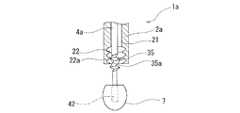
具体的には、ワイヤ4aの操作部7より所定長先端側となる部分は、ジグザグ状に変形した変形部35となっており、変形部35は、管状体2aの内面方向を向いた頂点を有する複数の屈曲部35aを備えている。また、管状体2aの基端部内面21には、環状エッジ22aを備えた複数の環状凹部22を備えている。そして、ワイヤ4aの屈曲部35aの頂点は、管状体2aの環状凹部22の環状エッジ22aと係合可能となっている。このため、ワイヤ4aを牽引し、ワイヤ4aのいずれかの屈曲部35aの頂点を、管状体2aのいずれかの環状凹部22の環状エッジ22aと係合させることにより、コイル部3の圧縮状態の保持がされる。また、係合するワイヤ4aの屈曲部35aの頂点と管状体2aの環状凹部22の環状エッジ22aとの組み合わせを変化させることにより、ガイドワイヤ先端部の変形の程度を選択することができる。具体的には、図5に示すワイヤ4aの屈曲部35aの頂点と管状体2aの環状凹部22の環状エッジ22aが係合しない状態では、コイル部3は、ほぼ直線状(変形前形状)である。また、図6に示すように、ワイヤ4aを牽引し、ワイヤ4aの屈曲部35aの頂点と管状体2aの環状凹部22の環状エッジ22aを係合させることにより、ガイドワイヤの先端部は、湾曲変形し、その状態が保持される。そして、ワイヤ4aの操作部7を操作し、ワイヤ4aの屈曲部35aの頂点と管状体2aの環状凹部22の環状エッジ22aと係合を離脱させることにより、ガイドワイヤの先端部は、変形前の形状に復帰する。5 and FIG. 6, the engagement mechanism between the
Specifically, the portion of the
また、ガイドワイヤ先端部変形状態保持機構としては、例えば、図7に示すガイドワイヤ1bが備えるタイプのものであってもよい。図7は、本発明のガイドワイヤの他の実施例の基端部の構造を説明するための説明図である。
図7に示すものでは、ガイドワイヤ先端部変形状態保持機構(ワイヤ4aと管状体2の係合機構)は、ワイヤ4aのワイヤ操作部7より先端側となる部位に軸方向に複数設けられた変形部と、変形部と係合可能な管状体2の基端開口部とにより構成されている。具体的には、図7に示すものでは、図5および図6に示したものと同様に、ワイヤ4aは、操作部7より所定長先端側となる部分には、ジグザグ状に変形した変形部35が設けられており、変形部35は、管状体2の内面方向を向いた頂点を有する複数の屈曲部35aを備えている。そして、管状体2は、図5および図6に示したもののような環状凹部を備えず、管状体2の基端開口部が、ワイヤ4aの変形部35の屈曲部35aと解除可能に係合するものとなっている。そして、この実施例のものにおいても、管状体2の基端開口部と係合するワイヤ4aの屈曲部35aの頂点を選択することにより、ガイドワイヤ先端部の変形の程度(コイル部3の圧縮状態の程度)を選択することができる。Moreover, as a guide wire front-end | tip part deformation | transformation state maintenance mechanism, the thing with which the
In the structure shown in FIG. 7, a plurality of guide wire tip portion deformed state holding mechanisms (mechanisms for engaging the
また、ガイドワイヤ先端部変形状態保持機構としては、例えば、図8に示すガイドワイヤ1cが備えるタイプのものであってもよい。図8は、本発明のガイドワイヤの他の実施例の基端部の外観図である。図9および図10は、図8に示したガイドワイヤの基端部の構造を説明するための説明図である。
図8ないし図10に示す実施例のガイドワイヤ1cでは、ガイドワイヤ先端部変形状態保持機構(ワイヤ4bと管状体2bとの係合機構)は、ワイヤ4bのワイヤ操作部7より先端側となる部位に設けられた変形部35と、管状体2bの基端部内面に軸方向に複数設けられ、変形部と係合可能な突出部27a,28aとにより構成されている。ワイヤ4bの変形部35としては、上述したガイドワイヤ1a、1bにて説明したものと同じである。なお、変形部35の形成位置は、上述したガイドワイヤ1a、1bと同様に、所定長先端側に位置し、図10に示すように、ワイヤ4bの牽引操作を行っても、変形部35が、管状体2bの基端部より露出しないものとなっている。Moreover, as a guide wire front-end | tip part deformation | transformation state holding mechanism, the thing of the type with which the
In the
図8および図9に示すように、管状体2bの基端より若干先端側となる部位の内面には、複数の突出部27a,28aを備えている。この実施例では、突出部27a,28aは、環状突出部となっている。また、2つの突出部27a,28aは、若干離間している。そして、ワイヤ4bの変形部35の屈曲部の頂点は、管状体2bの環状突出部27a,28aと係合可能となっている。このため、ワイヤ4bを牽引し、ワイヤ4bの変形部35のいずれかの屈曲部の頂点を、管状体2bのいずれかの環状突出部と係合させることにより、ガイドワイヤの先端部の変形状態(コイル部3の圧縮状態度)が保持される。また、係合するワイヤ4bの屈曲部の頂点と管状体2bの環状突出部との組み合わせを変化させることにより、コイル部3の圧縮状態、言い換えれば、コイル部3の直線状態への変形程度を選択することができる。また、この実施例のガイドワイヤ1cでは、突出部27a,28aは、管状体2bの外面より、環状にカシメることにより環状縮径部27,28を設け、その内面に環状突出部を形成させることにより、形成されている。そして、この実施例のガイドワイヤ1cでは、変形部35の形成位置は、ワイヤ4bの基端より所定長先端側に位置し、図10に示すように、ワイヤ4bの牽引操作を行っても(言い換えれば、牽引最大可能量牽引しても)、変形部35が、管状体2bの基端部より露出しないものとなっており、露出した変形部に起因するキンクを防止する。 As shown in FIGS. 8 and 9, a plurality of projecting
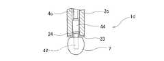
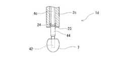
また、ガイドワイヤ先端部変形状態保持機構としては、例えば、図11および図12に示すガイドワイヤ1dが備えるタイプのものであってもよい。図11は、本発明のガイドワイヤの他の実施例の基端部の構造を説明するための説明図である。図12は、図11に示したガイドワイヤの作用を説明するための説明図である。
図11に示すガイドワイヤ1dでは、ガイドワイヤ先端部変形状態保持機構(ワイヤ4cと管状体2cの係合機構)は、ワイヤ4cのワイヤ操作部7より先端側となる部位に設けられた軸方向に延びる突出部と、管状体2cの基端部内面に設けられ、ワイヤ4cの突出部が圧接状態にて摺動可能な内面部とにより構成されている。特に、図11に示すガイドワイヤ1dでは、上記の突出部は、ワイヤ4cのワイヤ操作部7より先端側となる部位に設けられた拡径部44により形成されており、上記内面部は、管状体2cの基端部内面に設けられ、ワイヤ4cの拡径部44が圧接状態にて摺動可能な小径部24により構成されている。さらに、この実施例のガイドワイヤ1dでは、図11に示すように、管状体2cの基端開口部には、係合機構構成部材23が、固定されている。係合機構構成部材は、管状体2cの基端面に当接するフランジ部と、このフランジ部より突出し、管状体2cの基端部内に侵入する筒状部(小径部)24を備えている。また、ワイヤ4cは、図11に示すように、操作部7より所定長先端側となる部分に設けられた拡径部44を備えている。そして、拡径部44の外径は、構成部材23の円筒部(小径部)24の内径とほぼ等しく、図12に示すように、ワイヤ4cの拡径部44が圧接状態にて円筒部24の内面を摺動可能となっている。そして、拡径部44と構成部材23の円筒部(小径部)24は、拡径部44が、筒状部24内に位置する状態では、両者間の摩擦力により係合し、その状態を保持可能となっている。ワイヤ4cの拡径部は、ワイヤ4cと一体に形成されていてもよく、また、別部材を被嵌することにより、形成してもよい。Moreover, as a guide wire front-end | tip part deformation | transformation state holding mechanism, the thing of the type with which the
In the
係合機構構成部材23としては、金属材料により形成してもよいが、若干の弾性を備えることが好ましく、ポリオレフィン系、ポリアミド系、ポリアセタール系、ポリイミド系、フッ素系等の樹脂により形成してもよい。また、図13に示すガイドワイヤ1eのように、ワイヤの拡径部が圧接状態にて摺動可能な小径部29は、管状体2dの基端部に直接形成してもよく、さらに、ワイヤ4dの突出部は、拡径部ではなく、軸方向に延びるリブ44aにより形成してもよい。リブ44aは、軸方向に直線的に延びるものが好ましいが、螺旋的に延びるものであってもよい。また、リブ44aは、3以上であることが好ましく、図示するものでは、4つのリブを備えている。
そして、上述したガイドワイヤ1dおよび1eでは、拡径部44(または、リブ44a)は、小径部24(または、小径部29)の任意の位置にて両者間の摩擦力によりその位置を保持するため、ガイドワイヤの先端部の変形の程度は、段階的なものではなく、任意なものとすることができ、微妙な先端部の操作を可能としている。このことにより、術者が術中に先端部の所望形状を作ることが出来るので、通常は選択困難な分岐血管へ比較的容易に選択挿入することが可能となる。The engaging
In the above-described
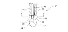
また、ガイドワイヤ先端部変形状態保持機構としては、例えば、図14ないし図17に示すガイドワイヤ1fが備えるタイプのものであってもよい。図14は、本発明のガイドワイヤの他の実施例の基端部の構造を説明するための説明図である。図15は、図14に示したガイドワイヤの作用を説明するための説明図である。図16は、図14のB−B線断面図である。図17は、図15のC−C線断面図である。
図14ないし図17に示すガイドワイヤ1fでは、ガイドワイヤ先端部変形状態保持機構(ワイヤと管状体の係合機構)は、ワイヤ4eのワイヤ操作部7より先端側となる部位に設けられた軸方向に延びる複数のリブ39と、管状体2eの基端部内面に設けられ、ワイヤ4eのリブ39を収納可能な軸方向に延びる溝部25とにより構成されている。そして、ワイヤ4eを牽引し、リブ39が、管状体2eに基端開口より露出した状態にて、ワイヤ操作部7を若干回転させることにより、リブ39は、管状体2eの基端面と当接し係合するものとなっている。Moreover, as a guide wire front-end | tip part deformation | transformation state holding mechanism, the thing of the type with which the
In the
特に、この実施例のガイドワイヤ1fでは、図14に示すように、ワイヤ4eは、操作部7より所定長先端側となる部分に設けられた拡径部38を備え、その表面に、軸方向(言い換えれば、ワイヤの中心軸に平行)に延びる複数(具体的には、3以上、図示するものでは、4つ)のリブ39を備えている。そして、管状体2eの基端部内面には、ワイヤ4eのリブ39を収納可能な軸方向(言い換えれば、管状体の中心軸に平行)に延びる複数(具体的には、3以上、図示するものでは、4つ)の溝部25を備えている。このため、ワイヤ4eのリブ39は、管状体2eの溝部25内を摺動可能となっている。なお、図16に示すように、ワイヤ4eのリブ39と管状体2eの溝部25間には、若干のクリアランスがあり、両者の摺動抵抗が、低いものとなっており、ワイヤ4eの基端方向の牽引が容易なものとなっている。そして、この実施例のガイドワイヤ1fでは、ワイヤ4eを牽引することにより、管状体2eに基端開口より露出し、そして、露出した状態にて、ワイヤ操作部7を若干回転させることにより、図15および図17に示すように、リブ39は、管状体2eの基端面と当接し係合し、ワイヤ4eが牽引された状態を保持する。 In particular, in the
また、図18に示すガイドワイヤ1gのように、ワイヤ4eのリブ39の代わりに、リブを操作部7に設けてもよい。この実施例のものでは、ワイヤ4fのワイヤ操作部7は、管状体2eの基端部内に進入する筒状部71を備え、その外面にワイヤ4fの軸方向に延びる複数のリブ72を有し、管状体2eの基端部内面には、ワイヤ4fの操作部7のリブ72を収納可能な軸方向に延びる溝部25を備えている。このため、係合機構は、ワイヤ操作部7の筒状部71の外面に設けられたリブ72と、管状体2eの基端部内面に設けられたリブ72を収納可能な溝部25により構成されている。この実施例において、ワイヤ4fを牽引し、リブ72が、管状体2eに基端開口より露出した状態にて、ワイヤ操作部7を若干回転させることにより、リブ72は、管状体2eの基端面と当接し係合する。 Moreover, you may provide a rib in the
また、ガイドワイヤ先端部変形状態保持機構としては、例えば、図19ないし図21に示すようなものであってもよい。図19は、本発明のガイドワイヤの他の実施例の基端部の外観図である。図20は、図19に示したガイドワイヤの基端部の断面図である。図21は、図19および図20に示したガイドワイヤの作用を説明するための説明図である。
図19ないし図21に示すガイドワイヤ1hでは、ガイドワイヤ先端部変形状態保持機構は、ワイヤ4gのワイヤ操作部7aより先端側に設けられ、ワイヤ4gの外面と圧接した状態にてワイヤ4gの先端方向および基端方向にスライド可能かつ、管状体2fの基端部と当接可能なスライド部材57と、管状体2fの基端部とにより構成されている。Moreover, as a guide wire front-end | tip part deformation | transformation state maintenance mechanism, what is shown, for example in FIG. 19 thru | or FIG. 21 may be used. FIG. 19 is an external view of the base end portion of another embodiment of the guide wire of the present invention. FIG. 20 is a cross-sectional view of the proximal end portion of the guide wire shown in FIG. FIG. 21 is an explanatory diagram for explaining the operation of the guide wire shown in FIGS. 19 and 20.
In the
このガイドワイヤ1hでは、ワイヤ4gは、ワイヤ操作部7aより先端側に設けられたスライド部材57を備えている。スライド部材57は、ワイヤ4gの外面と圧接した状態にてワイヤ4gの先端方向および基端方向にスライド可能なものとなっており、先端方向もしくは基端方向に強く押さない限り、ワイヤ4g上を動かないものとなっている。そして、このスライド部材57の先端面に管状体2fの後端面が当接し、両者が当接する状態では、ワイヤ4gの圧縮状態を保持するものとなっている。この実施例では、スライド部材57は、全体が筒状体であり、内部にワイヤ4gが貫通する内腔59を備えている。そして、内腔59の端部には、ワイヤ4gの外面を押圧するための環状リブ58が設けられている。なお、スライド部材57としては、内腔59の内面全体が、ワイヤ4gの外面に圧接するものであってもよい。 In the
そして、スライド部材57は、押すことにより、ワイヤ4g上を先端方向および基端方向に移動する。図19および図20に示す状態では、図22に示すように、ガイドワイヤのコイル部3は、湾曲した状態であるが、図21に示すように、図20に示す状態より、ワイヤ4gを牽引するとともに、スライド部材57をワイヤ4gの先端側に移動した状態(スライド部材57とコイル操作部7a間が離間した状態)では、図2に示すように、コイル部3は、ほぼ直線状となる。そして、スライド部材57は、管状体2fの後端面により押圧されるが、押圧力により、ワイヤ4gの基端側に移動することなく、その状態(コイルの牽引状態およびコイル部の変形状態)を保持する。また、この実施例では、コイル操作部7aは、ワイヤ4gの基端部42に固定された基端部材73と、基端部材73およびワイヤ4gの基端部に固定された所定長軸方向に延びる筒状部材74により形成されている。このため、一方の手で、操作部7aを保持し、他方の手で、スライド操作部の進退操作を行うことができ、コイルの牽引操作が良好に行われるものとなっている。そして、上述したガイドワイヤ1hでは、スライド部材57は、ワイヤ4gの任意の位置にて両者間の摩擦力によりその位置を保持するため、コイル部3は、元の湾曲状態からほぼ直線状までの間の任意の形状のものとすることが可能である。 The
また、上述したすべての実施例のガイドワイヤにおいて、ガイドワイヤの先端部構造は、例えば、図22ないし図24に示すようなものであってもよい。図22は、本発明のガイドワイヤの他の実施例の先端部の正面図である。図23は、図22に示したガイドワイヤの内部構造を説明するための説明図である。図24は、図22に示したガイドワイヤの作用を説明するための説明図である。
この実施例のガイドワイヤ10では、管状体2gは、先端から基端まで貫通したある程度の可撓性を有する中空体である。また、この実施例のものでは、管状体2gの先端部は、先端に向かって外径が縮径テーパー部となっている。
ワイヤ4hは、上述した管状体2g内を摺動可能に挿通しており、かつ、管状体2gの先端より、先端部が、基端より基端部が突出している。Moreover, in the guidewires of all the embodiments described above, the guidewire tip structure may be, for example, as shown in FIGS. FIG. 22 is a front view of the distal end portion of another embodiment of the guide wire of the present invention. FIG. 23 is an explanatory diagram for explaining the internal structure of the guide wire shown in FIG. FIG. 24 is an explanatory diagram for explaining the operation of the guide wire shown in FIG.
In the
The
ワイヤ4hの先端側部分には、ワイヤ4hの先端部を被包するとともに、先端部6aにてワイヤ4hの先端部と固定されたコイル部3を備えている。
特に、この実施例のガイドワイヤ10では、コイル部3は、略半球状のコイル部先端部11と、コイル部先端部11に先端6aが固定されたコイル体6と、コイル体6の基端6bに固定され、ワイヤ4hが貫通するリング状部材9とを備えている。そして、コイル体6は、その内面が、実質的にワイヤ4hの外面に接触しないものとなっている。このため、ワイヤ牽引時における、ワイヤとコイル体が摺接することがなく、ワイヤの牽引およびコイル体の変形を確実なものとしている。また、リング状部材9は、その中央部に設けられた開口を備え、ワイヤ4hは、開口内面に実質的に接触することなく、開口を貫通しており、ワイヤ牽引時における、ワイヤとリング状部材9が摺接することがなく、ワイヤの牽引を容易なものとしている。The distal end portion of the
In particular, in the
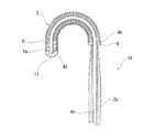
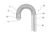
この実施例のものでは、コイル部3は、図22ないし図24に示すように、予め湾曲形状に形状付けされている。なお、湾曲形状としては、図22に示すようなU字型に限定されるものではなく、L字状、S字状、ループ状など任意の湾曲形状であってもよい。また、コイル部3は、予め形状付けされておらず、使用時に、操作者が指などを用いて、湾曲形状に形状付け可能なものであってもよい。この場合、コイル部3(具体的には、コイル体6)は、塑性変形可能なものにより形成される。
コイル体6は、例えば、Ni−Ti合金等の超弾性合金、ステンレス鋼、金、白金などの貴金属などの線材により形成されたものが好適である。そして、コイル体6の先端は、ワイヤ4hの先端に形成された略半球状のコイル部先端部11により固定されている。コイル部先端部11は、例えば、ロウにより形成される。そして、略半球状とは、実質的に曲面に成形されていることを意味し、例えば釣鐘状、弾丸状などの形状を含むものである。また、ワイヤ4hの先端45は、コイル部先端部11に固定されている。このため、ワイヤ4hを牽引することにより、コイル部先端部11が基端側に牽引される。In this embodiment, the
The
さらに、この実施例では、コイル体6の基端部には、ワイヤ4hが貫通するリング状部材9が固定されている。そして、このリング状部材9の基端面は、上述した管状体2gの先端面と当接可能となっている。なお、この実施例のものでは、コイル部3の基端部(具体的には、リング状部材9)は、管状体2gに固定されていない。そして、この実施例のガイドワイヤ10では、ワイヤ4hを基端方向に牽引することにより、コイル部3のリング状部材9の基端面は、管状体2gの先端面と当接し、さらに、牽引されることにより、コイル体6は、コイル部先端部11と管状体2gの先端面(リング状部材9)間により圧縮され、図24に示すように、湾曲形状からほぼ直線状態まで変形する。 Furthermore, in this embodiment, a ring-shaped member 9 through which the
また、上述したすべての実施例のガイドワイヤにおいて、ガイドワイヤの先端部構造は、例えば、図25に示すようなものであってもよい。図25は、本発明のガイドワイヤの他の実施例の先端部の構造を説明するための説明図である。
この実施例のガイドワイヤ20では、コイル体6の基端部にリング状部材が設けられておらず、また、管状体2hの先端部が、縮径していない。そして、コイル体6の基端部は、管状体2hの先端面に固定されている。このタイプのものでは、コイル体6が管状体2hに固定されているため、コイル体6と管状体2h間が離間することがない。Moreover, in the guidewires of all the embodiments described above, the guidewire tip structure may be, for example, as shown in FIG. FIG. 25 is an explanatory view for explaining the structure of the distal end portion of another embodiment of the guide wire of the present invention.
In the
また、上述したすべての実施例のガイドワイヤにおいて、ガイドワイヤの先端部構造は、例えば、図26に示すようなものであってもよい。図26は、本発明のガイドワイヤの他の実施例の先端部の構造を説明するための説明図である。
この実施例のガイドワイヤ30では、コイル部3aは、コイル部先端部11より基端側部分に設けられたワイヤ先端部固定部材31を備え、ワイヤ4iの先端が、ワイヤ先端部固定部材31に固定されており、コイル部3aは、ワイヤ4iの牽引による影響を受けない先端側コイル部32を備えている。そして、コイル本体6の先端6aは、コイル部先端部11に固定されており、基端6bは、リング状部材9に固定されており、先端6aより所定長基端側となるコイル体6の部位6cが、ワイヤ先端部固定部材31に固定されている。Moreover, in the guide wires of all the embodiments described above, the guide wire tip structure may be as shown in FIG. 26, for example. FIG. 26 is an explanatory view for explaining the structure of the distal end portion of another embodiment of the guide wire of the present invention.
In the
さらに、この実施例のものでは、ワイヤ4iの牽引による影響を受けない先端側コイル部32は、一端側がコイル部先端部11に固定され、他端がワイヤ先端部固定部31に接続された線状部材33を備えている。この実施例のものでは、ワイヤ4iが牽引されることにより、コイル体6が、圧縮され変形性が低下する場合があるが、先端側コイル部32は、ワイヤ4iの牽引により圧縮されることがないため、初期性状を保持し、例えば、良好な弾性を維持することができる。特に、この実施例のものでは、ワイヤ4iの牽引による影響を受けない先端側コイル部31は、ほぼ直線状となっている。また、ワイヤ4iの牽引による影響を受けない先端側コイル部31は、易塑性変形性を有し、形状付けが可能なものであってもよい。 Further, in this embodiment, the distal end
また、上述したすべての実施例のガイドワイヤにおいて、ガイドワイヤの先端部構造は、例えば、図27に示すようなものであってもよい。図27は、本発明のガイドワイヤの他の実施例の先端部の構造を説明するための説明図である。
この実施例のガイドワイヤ40において、上述したガイドワイヤ30と同様に、コイル部3bは、コイル部先端部11より基端側部分に設けられたワイヤ先端部固定部材31を備え、ワイヤ4iの先端が、ワイヤ先端部固定部材31に固定されており、コイル部3bは、ワイヤ4iの牽引による影響を受けない先端側コイル部32aを備えている。そして、この実施例のものでは、コイル部3bは、ワイヤ先端部固定部材31に先端61aが固定された本体側コイル部材61と、コイル部先端部11に先端62aが固定され、基端62bがワイヤ先端部固定部材31に固定された先端側コイル部材62とを備えている。また、本体側コイル部材61の基端61bは、リング状部材9に固定されている。そして、先端側コイル部材62は、本体側コイル部材61と物性が異なるものとなっている。そして、先端側コイル部材62を含む先端部固定部材31より先端側の部分にて、ワイヤ4iの牽引による影響を受けない先端側コイル部32aが形成されている。Moreover, in the guidewires of all the embodiments described above, the guidewire tip structure may be, for example, as shown in FIG. FIG. 27 is an explanatory view for explaining the structure of the distal end portion of another embodiment of the guide wire of the present invention.
In the
本体側コイル部材61と先端側コイル部材62の物性は、ガイドワイヤの目的に応じて種々選択可能である。例えば、本体側コイル部材61に比べて先端側コイル部材62は、易塑性変形性が高いものとすること(塑性変形性は、例えば、コイルの素線の素材を選択することにより変化させることができる)、基端側コイル部材61に比べて先端側コイル部材62は柔軟なものとすること(コイル柔軟性は、例えば、コイルの素線に一定の隙間を設けるか、素線を密着させて巻くかによって変えること、コイルの素線径を変えること、コイルの素材を変えることなどにより変化させることができる)、また、本体側コイル部材61に比べて先端側コイル部材は造影性が高いものとすることなどが考えられる。この実施例では、先端側コイル部材62の素線径は、本体側コイル部材61の素線径より細いものが用いられている。なお、先端側コイル部材62および本体側コイル部材61は、ほぼ同じ外径となっている。先端側コイル部材62の長さとしては、3〜30mm程度が好適であり、本体側コイル部材の長さとしては、30〜60mm程度が好適である。 Various physical properties of the main body
先端側コイル部材の形成材料としては、例えば、Ni−Ti合金等の超弾性合金、ステンレス鋼、金、白金などの貴金属などが使用できる。そして、先端側コイル部材と本体側コイル部材は、同じ材料により形成すること、また異なる材料により形成することのいずれでもよい。異なる材料を用いる場合には、例えば、先端側コイル部材としては、金、白金などの貴金属を用い、本体側コイル部材としては、ステンレス鋼を用いること、また、先端側コイル部材としては、超弾性合金を用い、本体側コイル部材としては、ステンレス鋼を用いることなどが考えられる。そして、この実施例のものでは、ワイヤ4iの牽引による影響を受けない先端側コイル部32aは、一端側がコイル部先端部11に固定され、他端がワイヤ先端部固定部31に接続された線状部材33を備えている。 As a material for forming the tip side coil member, for example, a superelastic alloy such as a Ni—Ti alloy, a noble metal such as stainless steel, gold, or platinum can be used. The tip side coil member and the main body side coil member may be formed of the same material or different materials. When using different materials, for example, a noble metal such as gold or platinum is used as the tip side coil member, stainless steel is used as the main body side coil member, and superelasticity is used as the tip side coil member. It is conceivable to use an alloy and use stainless steel as the main body side coil member. In this embodiment, the distal end
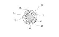
また、本発明のガイドワイヤにおいて、ガイドワイヤの先端部構造は、例えば、図28および図29に示すようなものであってもよい。図28は、本発明のガイドワイヤの他の実施例の先端部の構造を説明するための説明図である。図29は、図28のD−D線断面図である。
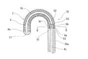
この実施例のガイドワイヤ70は、コイル部3の回動トルク付与機構を備えている。この実施例のガイドワイヤ70は、上述したガイドワイヤ10と同様に、コイル部3は、略半球状のコイル部先端部11と、コイル部先端部11に先端6aが固定されたコイル体6と、コイル体6の基端6bに固定され、ワイヤ4jが貫通するリング状部材9aとを備えている。コイル部3のリング状部材9aは、管状体50aに固定されていない。また、ワイヤ4jは、リング状部材9aの内腔を貫通している。そして、この実施例のガイドワイヤ70では、ワイヤ4jは、リング状部材9aの内腔内を摺動可能に設けられたトルク付与部材51を備えている。そして、トルク付与部材51は、その外面に、軸方向(言い換えれば、ワイヤの中心軸に平行)に延びる複数(具体的には、3以上、図示するものでは、4つ)のリブ52を備えている。そして、コイル部3のリング状部材9aは、内腔部の内面に、トルク付与部材51のリブ52が摺動可能な軸方向(言い換えれば、リング状部材の中心軸に平行)に延びる複数(具体的には、3以上、図示するものでは、4つ)の溝部91を備えている。Further, in the guide wire of the present invention, the distal end portion structure of the guide wire may be as shown in FIGS. 28 and 29, for example. FIG. 28 is an explanatory view for explaining the structure of the distal end portion of another embodiment of the guide wire of the present invention. 29 is a cross-sectional view taken along the line DD of FIG.
The
このため、ワイヤ4jのトルク付与部材51のリブ52は、リング状部材9aの溝部91内を摺動可能であり、トルク付与部材51は、ワイヤ4jの牽引を阻害しないものとなっている。さらに、ワイヤ4jに回転力を付与する(例えば、ワイヤ操作部7をひねる)ことにより、図29に示すように、トルク付与部51のリブ52の側面は、リング状部材9aの溝部91の側壁に当接するため、リング状部材9aに回転トルクが付与される。これにより、コイル部3全体に、回転トルクが付与される。さらに、この実施例のガイドワイヤ70では、リング状部材9aと管状体50a間には、摺動性付与部材53が設けられており、リング状部材9aと管状体50a間の摩擦抵抗を低減している。摺動性付与部材53は、リング状部材9aの基端面もしくは管状体50aの先端面に固定されることが好ましい。摺動性付与部材53としては、PTFE、ETFEなどの低摩擦抵抗性を有するフッ素系樹脂により形成することが好ましい。また、摺動性付与部材を設けることなく、リング状部材9aと管状体50a間にシリコーンオイルなどのオイルを付与し、摩擦抵抗を低減してもよい。 For this reason, the
そして、本発明のガイドワイヤとしては、図30に示すようなガイドワイヤ80であってもよい。図30は、本発明のガイドワイヤの他の実施例の内部構造を説明するための説明図である。
この実施例のガイドワイヤ80では、図19ないし図21に示し、上述したガイドワイヤ1hと同様に、ガイドワイヤ先端部変形状態保持機構は、ワイヤ4jのワイヤ操作部7aより先端側に設けられ、ワイヤ4jの外面と圧接した状態にてワイヤ4jの先端方向および基端方向にスライド可能かつ、管状体50aの基端部と当接可能なスライド部材57と、管状体50aの基端部とにより構成されている。また、コイル部3bは、図27に示し、上述したガイドワイヤ40と同様に、コイル部先端部11より基端側部分に設けられたワイヤ先端部固定部材31を備え、ワイヤ4jの先端が、ワイヤ先端部固定部材31に固定されており、コイル部3aは、ワイヤ4jの牽引による影響を受けない先端側コイル部32を備え、さらに、コイル部3bは、ワイヤ先端部固定部材31に先端61aが、リング状部材9aに基端61bが、固定された本体側コイル部材61と、コイル部先端部11に先端62aが固定され、基端62bがワイヤ先端部固定部材31に固定された先端側コイル部材62とを備えている。The guide wire of the present invention may be a
In the
そして、先端側コイル部材62は、本体側コイル部材61と物性が異なるものとなっている。さらに、コイル部3bは、図28および図29に示し、上述したガイドワイヤ70と同様に、コイル部3bの回動トルク付与機構を備えている。ガイドワイヤ80は、ワイヤ4jに固定され、リング状部材9aの内腔内を摺動可能に設けられたトルク付与部材51を備えている。そして、トルク付与部材51は、その外面に、軸方向に延びる複数のリブ52を備え、そして、コイル部3bのリング状部材9aは、内腔部の内面に、トルク付与部材51のリブ52が摺動可能な軸方向に延びる複数の溝部91を備えている。このため、ワイヤ4jに回転力を付与する(例えば、ワイヤ操作部7aをひねる)ことにより、リング状部材9aに回転トルクを付与可能であり、コイル部3全体に、回転トルクを付与することができるものとなっている。 The leading end
そして、すべての実施例において、ガイドワイヤの外面の全面もしくは所望部分の外面には、カテーテル等の筒状体内面との摩擦抵抗を低下させるための潤滑性付与剤をコーティングしてもよい。
潤滑性付与剤としては、水溶性高分子物質またはその誘導体が好ましく、例えば、ポリ(2−ヒドロキシエチルメタクリレート)、ポリヒドロキシエチルアクリレート、セルロース系高分子物質(例えば、ヒドロキシプロピルセルロース、ヒドロキシエチルセルロース)、無水マレイン酸系高分子物質(例えば、メチルビニルエーテル無水マレイン酸共重合体)、アクリルアミド系高分子物質(例えば、ポリアクリルアミド、ポリグリシジルメタクリレート−ジメチルアクリルアミド(PGMA−DMAA)のブロック共重合体)、ポリエチレンオキサイド系高分子物質(例えば、ポリエチレンオキサイド、ポリエチレングリコール)、ポリビニルアルコール、ポリアクリル酸系高分子物質(例えば、ポリアクリル酸ソーダ)、フタル酸系高分子物質(例えば、ポリヒドロキシエチルフタル酸エステル)、水溶性ポリエステル(例えば、ポリジメチロールプロピオン酸エステル)、ケトンアルデヒド樹脂(例えば、メチルイソプロピルケトンホルムアルデヒド)、ポリビニルピロリドン、ポリエチレンイミン、ポリスチレンスルホネート、水溶性ナイロン、ポリビニルアルコールなどが使用できる。In all of the embodiments, the entire outer surface of the guide wire or the outer surface of a desired portion may be coated with a lubricity imparting agent for reducing the frictional resistance with the inner surface of the tubular body such as a catheter.
As the lubricity imparting agent, a water-soluble polymer substance or a derivative thereof is preferable. For example, poly (2-hydroxyethyl methacrylate), polyhydroxyethyl acrylate, a cellulose-based polymer substance (for example, hydroxypropylcellulose, hydroxyethylcellulose), Maleic anhydride polymer (eg, methyl vinyl ether maleic anhydride copolymer), acrylamide polymer (eg, polyacrylamide, polyglycidyl methacrylate-dimethylacrylamide (PGMA-DMAA) block copolymer), polyethylene Oxide polymer materials (eg, polyethylene oxide, polyethylene glycol), polyvinyl alcohol, polyacrylic acid polymer materials (eg, sodium polyacrylate), phthalic acid-based polymers Child substances (for example, polyhydroxyethyl phthalate), water-soluble polyester (for example, polydimethylol propionate), ketone aldehyde resin (for example, methyl isopropyl ketone formaldehyde), polyvinyl pyrrolidone, polyethyleneimine, polystyrene sulfonate, water-soluble nylon Polyvinyl alcohol can be used.
1、1a,1b,1c,1d,1e,1f,1g,1h,10,20,30,40,50,60,70,80 ガイドワイヤ
2 管状体
3 コイル部
4 ワイヤ
7 ワイヤ操作部1, 1a, 1b, 1c, 1d, 1e, 1f, 1g, 1h, 10, 20, 30, 40, 50, 60, 70, 80
Claims (14)
Translated fromJapanese前記ワイヤ操作部の最大径部分は、前記管状体の外径と同等もしくはそれより小さく、前記コイル部は、直線状または湾曲形状もしくは湾曲形状に形状付け可能であり、かつ、前記コイル部に被包された前記ガイドワイヤの先端部は、前記ワイヤの基端方向への牽引により、前記直線状から湾曲形状へもしくは前記湾曲形状からほぼ直線状に変形可能であり、さらに、前記ワイヤおよび前記管状体は、前記ワイヤ操作部の軸方向への操作により、前記先端部の変形および変形を保持するためのガイドワイヤ先端部変形状態保持機構を備えていることを特徴とするガイドワイヤ。A tubular body, a wire that is slidably inserted through the tubular body, a coil portion that encloses a distal end portion of the wire, and a wire operation portion provided at a proximal end portion exposed from the tubular body of the wire A guide wire comprising:
The maximum diameter portion of the wire operation portion is equal to or smaller than the outer diameter of the tubular body, the coil portion can be formed into a linear shape, a curved shape, or a curved shape, and the coil portion is covered with the coil portion. The distal end portion of the wrapped guide wire can be deformed from the linear shape to the curved shape or from the curved shape to a substantially linear shape by pulling in the proximal direction of the wire, and further, the wire and the tubular shape The body is provided with a guide wire tip portion deformation state holding mechanism for holding deformation and deformation of the tip portion by an operation of the wire operation portion in the axial direction.
Priority Applications (2)
| Application Number | Priority Date | Filing Date | Title |
|---|---|---|---|
| JP2011214697AJP2014236757A (en) | 2011-09-29 | 2011-09-29 | Guide wire |
| PCT/JP2012/074782WO2013047616A1 (en) | 2011-09-29 | 2012-09-26 | Guidewire |
Applications Claiming Priority (1)
| Application Number | Priority Date | Filing Date | Title |
|---|---|---|---|
| JP2011214697AJP2014236757A (en) | 2011-09-29 | 2011-09-29 | Guide wire |
Publications (1)
| Publication Number | Publication Date |
|---|---|
| JP2014236757Atrue JP2014236757A (en) | 2014-12-18 |
Family
ID=47995647
Family Applications (1)
| Application Number | Title | Priority Date | Filing Date |
|---|---|---|---|
| JP2011214697APendingJP2014236757A (en) | 2011-09-29 | 2011-09-29 | Guide wire |
Country Status (2)
| Country | Link |
|---|---|
| JP (1) | JP2014236757A (en) |
| WO (1) | WO2013047616A1 (en) |
Cited By (2)
| Publication number | Priority date | Publication date | Assignee | Title |
|---|---|---|---|---|
| WO2019163248A1 (en)* | 2018-02-23 | 2019-08-29 | テルモ株式会社 | Guide wire |
| JP2020514004A (en)* | 2017-02-01 | 2020-05-21 | アクラレント インコーポレイテッドAcclarent, Inc. | Navigation guide wire with meshing coil |
Families Citing this family (3)
| Publication number | Priority date | Publication date | Assignee | Title |
|---|---|---|---|---|
| WO2017154164A1 (en)* | 2016-03-10 | 2017-09-14 | 朝日インテック株式会社 | Guide wire |
| CN110831532B (en)* | 2017-06-29 | 2023-03-21 | 朝日英达科株式会社 | Guide wire for plasma |
| CN111514457A (en)* | 2019-02-01 | 2020-08-11 | 微创龙脉医疗科技(嘉兴)有限公司 | Guide wire twisting device and guiding device |
Family Cites Families (5)
| Publication number | Priority date | Publication date | Assignee | Title |
|---|---|---|---|---|
| US6911036B2 (en)* | 2001-04-03 | 2005-06-28 | Medtronic Vascular, Inc. | Guidewire apparatus for temporary distal embolic protection |
| JP2004249095A (en)* | 2003-01-31 | 2004-09-09 | Piolax Medical Device:Kk | Guide wire |
| JP4677205B2 (en)* | 2003-07-17 | 2011-04-27 | テルモ株式会社 | Guide wire |
| JP2005342470A (en)* | 2004-06-03 | 2005-12-15 | Ys Medical:Kk | Medical guide wire |
| JP2010207251A (en)* | 2009-03-06 | 2010-09-24 | Olympus Corp | Guide wire |
- 2011
- 2011-09-29JPJP2011214697Apatent/JP2014236757A/enactivePending
- 2012
- 2012-09-26WOPCT/JP2012/074782patent/WO2013047616A1/enactiveApplication Filing
Cited By (3)
| Publication number | Priority date | Publication date | Assignee | Title |
|---|---|---|---|---|
| JP2020514004A (en)* | 2017-02-01 | 2020-05-21 | アクラレント インコーポレイテッドAcclarent, Inc. | Navigation guide wire with meshing coil |
| JP7229940B2 (en) | 2017-02-01 | 2023-02-28 | アクラレント インコーポレイテッド | Navigation guidewire with mating coil |
| WO2019163248A1 (en)* | 2018-02-23 | 2019-08-29 | テルモ株式会社 | Guide wire |
Also Published As
| Publication number | Publication date |
|---|---|
| WO2013047616A1 (en) | 2013-04-04 |
Similar Documents
| Publication | Publication Date | Title |
|---|---|---|
| US10870143B2 (en) | Connection structure and connection method | |
| CN106943218B (en) | Implant Delivery System | |
| US8608670B2 (en) | Guidewire | |
| WO2013047616A1 (en) | Guidewire | |
| JP4598181B2 (en) | Endoscopic clip device | |
| JP2011000188A (en) | Medical guidewire | |
| EP2845620A1 (en) | Coil body and medical apparatus using said coil body | |
| US9993141B2 (en) | Control system for medical devices and related methods of use | |
| US10045762B2 (en) | Dilation device and expandable covering for a dilation instrument | |
| US20160051278A1 (en) | Surgical Snare Device | |
| JP6405274B2 (en) | Guide wire | |
| JP2008119077A (en) | Stent supply device | |
| JPH04108456A (en) | Guide wire for medical treatment | |
| WO2021010222A1 (en) | Implant device | |
| WO2018062155A1 (en) | Guide wire | |
| JP2019097907A (en) | Snare for endoscope | |
| JP4441509B2 (en) | Endoscopic treatment tool | |
| JP2019146705A (en) | Guide wire | |
| JP2017221562A (en) | Guide wire | |
| JP2010124913A (en) | Treatment instrument for endoscope | |
| JP2008307380A (en) | Medical instruments | |
| JP2007275518A (en) | Clip for endoscope | |
| JPWO2022075183A5 (en) | ||
| JP5459723B2 (en) | Medical guidewire | |
| JP5780532B2 (en) | Medical guidewire |