JP2014236539A - Power transmission device for non-contact charging and travelling control system of electric vehicle - Google Patents
Power transmission device for non-contact charging and travelling control system of electric vehicleDownload PDFInfo
- Publication number
- JP2014236539A JP2014236539AJP2013114927AJP2013114927AJP2014236539AJP 2014236539 AJP2014236539 AJP 2014236539AJP 2013114927 AJP2013114927 AJP 2013114927AJP 2013114927 AJP2013114927 AJP 2013114927AJP 2014236539 AJP2014236539 AJP 2014236539A
- Authority
- JP
- Japan
- Prior art keywords
- power transmission
- coil
- power
- tile
- transmission device
- Prior art date
- Legal status (The legal status is an assumption and is not a legal conclusion. Google has not performed a legal analysis and makes no representation as to the accuracy of the status listed.)
- Pending
Links
- 230000005540biological transmissionEffects0.000titleclaimsabstractdescription98
- 239000000463materialSubstances0.000claimsabstractdescription13
- 238000009408flooringMethods0.000claimsdescription6
- 238000000034methodMethods0.000description5
- 239000003990capacitorSubstances0.000description4
- 239000000919ceramicSubstances0.000description2
- 230000004048modificationEffects0.000description2
- 238000012986modificationMethods0.000description2
- 238000009774resonance methodMethods0.000description2
- 230000008878couplingEffects0.000description1
- 238000010168coupling processMethods0.000description1
- 238000005859coupling reactionMethods0.000description1
- 238000010586diagramMethods0.000description1
- 230000005674electromagnetic inductionEffects0.000description1
- 238000000465mouldingMethods0.000description1
Images


Classifications
- Y—GENERAL TAGGING OF NEW TECHNOLOGICAL DEVELOPMENTS; GENERAL TAGGING OF CROSS-SECTIONAL TECHNOLOGIES SPANNING OVER SEVERAL SECTIONS OF THE IPC; TECHNICAL SUBJECTS COVERED BY FORMER USPC CROSS-REFERENCE ART COLLECTIONS [XRACs] AND DIGESTS
- Y02—TECHNOLOGIES OR APPLICATIONS FOR MITIGATION OR ADAPTATION AGAINST CLIMATE CHANGE
- Y02P—CLIMATE CHANGE MITIGATION TECHNOLOGIES IN THE PRODUCTION OR PROCESSING OF GOODS
- Y02P90/00—Enabling technologies with a potential contribution to greenhouse gas [GHG] emissions mitigation
- Y02P90/60—Electric or hybrid propulsion means for production processes
Landscapes
- Charge And Discharge Circuits For Batteries Or The Like (AREA)
- Electric Propulsion And Braking For Vehicles (AREA)
- Control Of Position, Course, Altitude, Or Attitude Of Moving Bodies (AREA)
Abstract
Description
Translated fromJapanese本発明は、非接触充電用送電装置及び電動車両の走行制御システムに関し、特に工場内等を走行する無人搬送車(以下、「AGV」という)の充電に好適な非接触充電用送電装置に関する。 The present invention relates to a non-contact charging power transmission device and a travel control system for an electric vehicle, and more particularly to a non-contact charging power transmission device suitable for charging an automatic guided vehicle (hereinafter referred to as “AGV”) traveling in a factory or the like.
電気自動車やAGV等の電動車両の充電システムとして、非接触充電システムが知られている。例えば、特許文献1には、プリント基板の第1の層に設けられた一次コイルと、プリント基板の第2の層に設けられた共鳴コイルとを備えた、非接触充電システムに適用される送電装置が開示されている。 A contactless charging system is known as a charging system for electric vehicles such as electric vehicles and AGVs. For example, Patent Document 1 discloses a power transmission applied to a non-contact charging system including a primary coil provided in a first layer of a printed circuit board and a resonance coil provided in a second layer of the printed circuit board. An apparatus is disclosed.
ところで、従来の送電装置では、図6(給電線等は省略)に例示するように、AGV等が走行するタイル25上に送電コイル101が内蔵された送電ボックス100を設置する必要がある。このため、例えば当該送電ボックス100を工場内に設置すると、台車やリフト、作業者等の通行の妨げとなる。 By the way, in the conventional power transmission apparatus, it is necessary to install the
本発明に係る非接触充電用送電装置は、受電コイルを搭載した電動車両の走行路に配置される送電コイルと、前記送電コイルに電力を供給するための給電線とを備えた、前記電動車両の非接触充電システムに適用される送電装置であって、前記送電コイルは、前記走行路に設けられる床材に埋め込まれていることを特徴とする。また、当該送電装置において、前記給電線は、前記床材に埋め込まれていることが好適である。 A non-contact charging power transmission device according to the present invention includes a power transmission coil disposed on a traveling path of an electric vehicle equipped with a power receiving coil, and a power supply line for supplying power to the power transmission coil. It is a power transmission apparatus applied to the non-contact charging system, wherein the power transmission coil is embedded in a floor material provided in the travel path. In the power transmission device, it is preferable that the power supply line is embedded in the flooring.
本発明に係る電動車両の走行制御システムは、上記非接触充電用送電装置と、前記電動車両に搭載され、前記送電コイルの磁界を検出するセンサと、制御装置と、を備えた電動車両の走行制御システムであって、前記送電コイルが埋め込まれた前記床材は、前記走行路に沿って複数設けられ、前記制御装置は、前記センサにより検出された前記磁界に基づき前記電動車両を前記走行路に沿って自動走行させることを特徴とする。 A travel control system for an electric vehicle according to the present invention is the travel of an electric vehicle including the contactless power transmission device, a sensor that is mounted on the electric vehicle and detects a magnetic field of the power transmission coil, and a control device. In the control system, a plurality of the flooring in which the power transmission coil is embedded are provided along the travel path, and the control device moves the electric vehicle based on the magnetic field detected by the sensor. It is characterized by being automatically driven along.
本発明に係る非接触充電用送電装置によれば、送電コイルが床材に埋め込まれて一体化されているため、段差のない平坦な床面を形成することができる。これにより、送電装置が、台車やリフト、作業者等の通行の妨げとなることを防止できる。 According to the power transmission device for contactless charging according to the present invention, since the power transmission coil is embedded and integrated in the floor material, a flat floor surface without a step can be formed. Thereby, it can prevent that a power transmission apparatus obstructs traffic of a trolley | bogie, a lift, an operator, etc.
以下、図面を参照しながら、本発明の実施形態の一例について詳細に説明する。
なお、各図面(図2を除く)では、図面の明瞭化の観点から、実際には見えない送電コイル22等を実線で図示している。Hereinafter, an example of an embodiment of the present invention will be described in detail with reference to the drawings.
In each drawing (excluding FIG. 2), the
以下では、工場内を自動走行するAGVの非接触充電システム10を例に挙げて本発明の実施形態を説明するが、本発明の適用はこれに限定されない。本発明の送電装置は、例えば駐車場やサービスステーション等に設置され、電気自動車やハイブリッド車の非接触充電に適用することもできる。 Hereinafter, an embodiment of the present invention will be described by taking an AGV
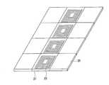
図1は、第1の実施形態である非接触充電システム10の概略構成を示す。
図1に示すように、非接触充電システム10は、送電装置20と、AGV11に搭載される受電装置30と、各装置を制御してAGV11の非接触充電を実行する制御装置40とを備える。AGV11の走行路には、例えば走行ライン12が描かれており、AGV11は当該ラインに沿って自動走行する。本実施形態では、かかる自動走行も制御装置40の機能により実行される。FIG. 1 shows a schematic configuration of a
As shown in FIG. 1, the
非接触充電システム10は、AGV11の走行路、即ち走行ライン12に沿って送電装置20を構成する複数の送電コイル22を備え、AGV11の走行中における非接触充電を可能とする。例えば、送電コイル22の上にAGV11の受電装置30が位置するときに、送電コイル22から電力伝送用の電磁波が送電される。そして、受電装置30の受電コイル31により当該電磁波を受波し、これに基づく電力によってAGV11に搭載されたバッテリ13が充電される。 The
本実施形態では、AGV11が走行する工場の床に、床材として複数のタイル25が配置されている。タイル25は、工場の床材として使用される一般的なタイルである。そして、詳しくは後述するように、床材の一部にコイル内蔵タイル21が用いられている。 In the present embodiment, a plurality of
送電装置20は、走行ライン12に沿って配置された複数の送電コイル22、各送電コイル22と図示しない電源回路とを接続して各送電コイル22に電力を供給するための給電線24、及び図示しないキャパシタ等を備える。送電コイル22は、電力伝送用の電磁波を送電する送電部としての機能を有する。送電コイル22は、例えば平面状に周回する導線によって形成される。 The
受電装置30は、電力伝送用の電磁波を受波する受波部としての機能を有する受電コイル31、受電コイル31とバッテリ13との間に設けられる充電回路32、及び図示しないキャパシタ等を備える。即ち、受電コイル31は充電回路32に接続され、充電回路32にはバッテリ13が接続されている。受電コイル31は、例えば送電コイル22と同様に、平面状に周回する導線(コイル線)によって形成される。 The
非接触充電(給電)の方式は、特に限定されず、例えば電磁誘導方式、共鳴方式のいずれであってもよい。共鳴方式の場合、送電コイル22から受電コイル31への電力伝送は、送電コイル22側の回路と受電コイル31側の回路との結合共振(共鳴)によって行われる。送電コイル22は、例えばキャパシタと共に送電側の共振回路を形成し、受電コイル31は、キャパシタと共に受電側の共振回路を形成する。送電側と受電側とで共振周波数を同一の周波数とし、送電側の共振回路と受電側の共振回路を該周波数で結合共振させる。これにより、送電コイル22と受電コイル31とを機械的に接触させることなく、送電装置20からAGV11に電力を供給することができる。 The method of non-contact charging (power feeding) is not particularly limited, and for example, either an electromagnetic induction method or a resonance method may be used. In the case of the resonance method, power transmission from the
以下、図2をさらに参照して、送電装置20の構成について詳説する。
図2は、図1のA−A線断面、即ちコイル内蔵タイル21を給電線24の長手方向に対して直交する方向に切断した断面を模式的に示す図である。Hereinafter, the configuration of the
FIG. 2 is a diagram schematically showing a cross section taken along the line AA of FIG.
図1,2に示すように、送電コイル22は、AGV11の走行路に設けられる床材(タイル材23)に埋め込まれている。即ち、AGV11の走行路には、コイル内蔵タイル21が設けられている。コイル内蔵タイル21は、AGV11の走行路に沿って複数設けられることが好適である。これにより、非接触充電システム10は、AGV11の走行中における非接触充電を可能とする。 As shown in FIGS. 1 and 2, the
1枚のコイル内蔵タイル21は、例えば1つの送電コイル22と、タイル材23とで構成される。コイル内蔵タイル21を構成するタイル材23には、一般的なタイル25と同じ材料、例えばセラミックス(陶磁器)、プラスチック、コンクリート等を用いることができる。即ち、コイル内蔵タイル21は、送電コイル22がタイル材23で被覆され保護された構造である。 One
コイル内蔵タイル21の形状は、特に限定されず、例えば40cm角〜50cm角程度の寸法を有する四角形状のパネルとすることができる。コイル内蔵タイル21の寸法は、タイル25と略同等であることが好ましい。また、コイル内蔵タイル21に埋め込まれて一体化される送電コイル22は、図1に示す丸型コイルに限定されず、図3(給電線24を省略)に示す角型コイル等、その他の形状であってもよい。 The shape of the coil built-in
コイル内蔵タイル21は、例えば2枚のタイル材23を準備して送電コイル22を挟み込んで製造されてもよいし、タイル材23にプラスチック材料等を用いたインサート成形により製造されてもよい。 The tile with built-in
コイル内蔵タイル21には、さらに給電線24が埋め込まれていることが好適である。給電線24は、各コイル内蔵タイル21の送電コイル22と、電源回路とを接続するケーブルである。給電線24をタイルに埋め込むことで、例えば給電線24の破損が抑制され、また給電線24が通行の邪魔になることを防止できる。なお、各送電コイル22への給電方法は、特に限定されないが、各送電コイル22への給電をON/OFFするスイッチ等を設け、AGV11の走行に合わせて当該ON/OFFを実行できることが好ましい。 It is preferable that a
コイル内蔵タイル21には、AGV11の自動走行に使用するトレースセンサを埋め込むこともできる。トレースセンサとして磁気センサを用いる場合は、例えばコイル内蔵タイル21に磁石や磁気テープを埋め込み、AGV11に当該磁石等の磁力を検出する検出器を搭載することができる。この場合、磁石等をタイルに埋め込むことで、例えば磁石等の破損が抑制され、また磁石等が通行の邪魔になることを防止できる。その他、コイル内蔵タイル21の表面に描かれた走行ライン12を赤外線センサ等で検出する方法も挙げられるが、本実施形態では後述の方法によりAGV11の走行制御を実行するものとする。 A trace sensor used for automatic traveling of the AGV 11 can also be embedded in the coil built-in
非接触充電システム10は、上記のように、制御装置40を備える。制御装置40は、送電装置20及び受電装置30を制御してAGV11の非接触充電を実行する充電制御手段41を有する。本実施形態では、制御装置40がAGV11の自動走行を制御する走行制御手段42をさらに有する。 The
充電制御手段41は、例えばAGV11の走行に合わせて各コイル内蔵タイル21に埋め込まれた送電コイル22への給電をON/OFFする。即ち、コイル内蔵タイル21が配置された走行路に沿って自動走行するAGV11の直下に位置する送電コイル22に対して選択的に給電することが好ましい。そして、上記のように、送電側と受電側とで共振周波数を同一の周波数とし、送電側の共振回路と受電側の共振回路を該周波数で結合共振させて送電装置20からAGV11に電力を供給する。 The charge control means 41 turns ON / OFF the power supply to the
走行制御手段42は、AGV11の走行制御システムの一部を構成する。走行制御システムは、送電コイル22の磁界を検出する磁気センサ14を有する。磁気センサ14は、AGV11に搭載されている。走行制御手段42は、磁気センサ14により検出された送電コイル22の磁界に基づきAGV11を走行路に沿って自動走行させる機能を有する。これにより、磁石や磁気テープ等をタイルに埋め込むことなく、送電コイル22の磁界を利用してAGV11の走行路に沿った自動走行を可能とする。 The traveling control means 42 constitutes a part of the traveling control system of the
以上のように、受電装置30を備える非接触充電システム10によれば、送電コイル22、給電線24、必要によりトレースセンサがタイルに埋め込まれて一体化されているため、段差のない平坦な床面を形成することができる。これにより、送電装置20が、台車やリフト、作業者等の通行の妨げとなることを防止できる。 As described above, according to the
図4(給電線を省略)は、第2の実施形態である送電装置20xを示す。
以下では、上記実施形態との相違点について詳説し、重複する説明は省略する。FIG. 4 (a power supply line is omitted) shows a
Hereinafter, differences from the above-described embodiment will be described in detail, and redundant description will be omitted.
図4に示すように、送電装置20xでは、複数のコイル線内蔵タイル21xを組み合わせて1つの送電コイル22xが構成される。送電コイル22xは、例えば平面状に10回程度巻かれた角型コイルであって、コイル線内蔵タイル21xには、直線状のコイル線が内蔵されたタイルと、略L字状に曲がったコイル線が内蔵されたタイルとが含まれる。図4に示す例では、これら2種類のコイル線内蔵タイル21xに埋め込まれたコイル線同士を接続して、合計8枚のコイル線内蔵タイル21xを連結し、1つの送電コイル22xを構成している。 As shown in FIG. 4, in the
なお、図5に示すように、走行ライン12xが湾曲している場合であっても、複数のコイル線内蔵タイル21xを組み合わせて1つの送電コイル22xを構成することができる。この場合、コイル線内蔵タイル21xに埋め込まれたコイル線も走行ライン12xに沿って湾曲している。 As shown in FIG. 5, even if the
送電装置20xによれば、図1に示す例と比べて、走行路に沿った送電コイルの数が少なくなり、送電コイル同士の間隙の数も少なくなる。このため、AGV11の走行中における充電効率を向上させることができる。 According to the
10 非接触充電システム、11 AGV、12,12x 走行ライン、13 バッテリ、14 磁気センサ、20,20x 送電装置、21 コイル内蔵タイル、22,22x 送電コイル、23 タイル材、24 給電線、25 タイル、30 受電装置、31 受電コイル、32 充電回路、40 制御装置、41 充電制御手段、42 走行制御手段、100 送電ボックス、101 送電コイル 10 contactless charging system, 11 AGV, 12, 12x travel line, 13 battery, 14 magnetic sensor, 20, 20x power transmission device, 21 coil built-in tile, 22, 22x power transmission coil, 23 tile material, 24 feed line, 25 tile, DESCRIPTION OF
Claims (3)
Translated fromJapanese前記送電コイルに電力を供給するための給電線と、
を備えた、前記電動車両の非接触充電システムに適用される送電装置であって、
前記送電コイルは、前記走行路に設けられる床材に埋め込まれていることを特徴とする非接触充電用送電装置。A power transmission coil disposed on a traveling path of an electric vehicle equipped with a power reception coil;
A feed line for supplying power to the power transmission coil;
A power transmission device applied to the non-contact charging system for the electric vehicle,
The power transmission coil is embedded in a floor material provided on the travel path, and is a power transmission device for non-contact charging.
前記給電線は、前記床材に埋め込まれていることを特徴とする非接触充電用送電装置。The power transmission device for contactless charging according to claim 1,
The power feeding device for contactless charging, wherein the power supply line is embedded in the flooring.
前記電動車両に搭載され、前記送電コイルの磁界を検出するセンサと、
制御装置と、
を備えた電動車両の走行制御システムであって、
前記送電コイルが埋め込まれた前記床材は、前記走行路に沿って複数設けられ、
前記制御装置は、前記センサにより検出された前記磁界に基づき前記電動車両を前記走行路に沿って自動走行させることを特徴とする電動車両の走行制御システム。A power transmission device for contactless charging according to claim 1 or 2,
A sensor mounted on the electric vehicle for detecting the magnetic field of the power transmission coil;
A control device;
An electric vehicle travel control system comprising:
A plurality of the flooring in which the power transmission coil is embedded are provided along the traveling path,
The control device causes the electric vehicle to automatically travel along the travel path based on the magnetic field detected by the sensor.
Priority Applications (1)
| Application Number | Priority Date | Filing Date | Title |
|---|---|---|---|
| JP2013114927AJP2014236539A (en) | 2013-05-31 | 2013-05-31 | Power transmission device for non-contact charging and travelling control system of electric vehicle |
Applications Claiming Priority (1)
| Application Number | Priority Date | Filing Date | Title |
|---|---|---|---|
| JP2013114927AJP2014236539A (en) | 2013-05-31 | 2013-05-31 | Power transmission device for non-contact charging and travelling control system of electric vehicle |
Publications (1)
| Publication Number | Publication Date |
|---|---|
| JP2014236539Atrue JP2014236539A (en) | 2014-12-15 |
Family
ID=52138890
Family Applications (1)
| Application Number | Title | Priority Date | Filing Date |
|---|---|---|---|
| JP2013114927APendingJP2014236539A (en) | 2013-05-31 | 2013-05-31 | Power transmission device for non-contact charging and travelling control system of electric vehicle |
Country Status (1)
| Country | Link |
|---|---|
| JP (1) | JP2014236539A (en) |
Cited By (15)
| Publication number | Priority date | Publication date | Assignee | Title |
|---|---|---|---|---|
| CN104635733A (en)* | 2014-12-03 | 2015-05-20 | 国家电网公司 | Automatic guided vehicle and control method thereof |
| CN105128686A (en)* | 2015-08-12 | 2015-12-09 | 上海海事大学 | Automatic charging ground equipment for all-electric unmanned automatic navigation carrying cart in automated container terminal and charging method |
| CN105549596A (en)* | 2016-02-04 | 2016-05-04 | 长沙长泰机器人有限公司 | Storehouse intelligent storage system and material transferring method |
| CN107068360A (en)* | 2017-01-06 | 2017-08-18 | 南通华为电力设备有限公司 | Large-area Magnetic Field equilibrium array coil and regulating step and its wireless charging device |
| CN107102370A (en)* | 2017-04-11 | 2017-08-29 | 北京华力兴科技发展有限责任公司 | Control method, control device and the vehicle inspection system based on AGV |
| WO2017182130A1 (en)* | 2016-04-22 | 2017-10-26 | Sew-Eurodrive Gmbh & Co. Kg | Method for operating a production plant comprising a vehicle and at least one charging point, and production plant having a vehicle for carrying out said method |
| ITUA20164413A1 (en)* | 2016-06-15 | 2017-12-15 | Simone Marini | Multi-purpose container that can be opened, also with the function of building tile for lighting applications, home automation and audio amplification |
| WO2018159540A1 (en) | 2017-02-28 | 2018-09-07 | 株式会社Ihi | Ground-side power supply device |
| CN108923476A (en)* | 2018-05-31 | 2018-11-30 | 许继电源有限公司 | A kind of electric car direct current wireless charging system |
| WO2019065317A1 (en)* | 2017-09-29 | 2019-04-04 | 日本電産株式会社 | Moving body |
| CN109641668A (en)* | 2016-06-30 | 2019-04-16 | 史蒂文·丹尼斯·约翰·科斯特洛 | Improvements to aircraft taxiing |
| CN111375936A (en)* | 2020-03-02 | 2020-07-07 | 中国第一汽车股份有限公司 | AGV carries movable platform truck fine positioning system |
| EP3699020A1 (en)* | 2019-02-22 | 2020-08-26 | Arrival Limited | Wireless battery charging system for automatic guided vehicles |
| US20220116079A1 (en)* | 2019-06-21 | 2022-04-14 | Huawei Technologies Co., Ltd. | Magnetic induction communication-based vehicle control apparatus and method |
| JP2024050142A (en)* | 2022-09-29 | 2024-04-10 | 株式会社神戸製鋼所 | Monitoring system |
Citations (1)
| Publication number | Priority date | Publication date | Assignee | Title |
|---|---|---|---|---|
| JPH03235432A (en)* | 1990-02-09 | 1991-10-21 | Kubota Corp | information storage medium |
- 2013
- 2013-05-31JPJP2013114927Apatent/JP2014236539A/enactivePending
Patent Citations (1)
| Publication number | Priority date | Publication date | Assignee | Title |
|---|---|---|---|---|
| JPH03235432A (en)* | 1990-02-09 | 1991-10-21 | Kubota Corp | information storage medium |
Cited By (22)
| Publication number | Priority date | Publication date | Assignee | Title |
|---|---|---|---|---|
| CN104635733A (en)* | 2014-12-03 | 2015-05-20 | 国家电网公司 | Automatic guided vehicle and control method thereof |
| CN105128686A (en)* | 2015-08-12 | 2015-12-09 | 上海海事大学 | Automatic charging ground equipment for all-electric unmanned automatic navigation carrying cart in automated container terminal and charging method |
| CN105549596A (en)* | 2016-02-04 | 2016-05-04 | 长沙长泰机器人有限公司 | Storehouse intelligent storage system and material transferring method |
| US10730404B2 (en) | 2016-04-22 | 2020-08-04 | Sew-Eurodrive Gmbh & Co. Kg | Method for operating a production plant comprising a vehicle and at least one charging point, and production plant having a vehicle for carrying out the method |
| WO2017182130A1 (en)* | 2016-04-22 | 2017-10-26 | Sew-Eurodrive Gmbh & Co. Kg | Method for operating a production plant comprising a vehicle and at least one charging point, and production plant having a vehicle for carrying out said method |
| ITUA20164413A1 (en)* | 2016-06-15 | 2017-12-15 | Simone Marini | Multi-purpose container that can be opened, also with the function of building tile for lighting applications, home automation and audio amplification |
| CN109641668A (en)* | 2016-06-30 | 2019-04-16 | 史蒂文·丹尼斯·约翰·科斯特洛 | Improvements to aircraft taxiing |
| JP2019521903A (en)* | 2016-06-30 | 2019-08-08 | コステロ、 スティーヴン デニス ジョンCOSTELLO, Steven Dennis John | Improved aircraft taxiing |
| CN107068360A (en)* | 2017-01-06 | 2017-08-18 | 南通华为电力设备有限公司 | Large-area Magnetic Field equilibrium array coil and regulating step and its wireless charging device |
| US10857893B2 (en) | 2017-02-28 | 2020-12-08 | Ihi Corporation | Ground-side power supply device |
| WO2018159540A1 (en) | 2017-02-28 | 2018-09-07 | 株式会社Ihi | Ground-side power supply device |
| CN107102370A (en)* | 2017-04-11 | 2017-08-29 | 北京华力兴科技发展有限责任公司 | Control method, control device and the vehicle inspection system based on AGV |
| WO2019065317A1 (en)* | 2017-09-29 | 2019-04-04 | 日本電産株式会社 | Moving body |
| CN108923476A (en)* | 2018-05-31 | 2018-11-30 | 许继电源有限公司 | A kind of electric car direct current wireless charging system |
| EP3699020A1 (en)* | 2019-02-22 | 2020-08-26 | Arrival Limited | Wireless battery charging system for automatic guided vehicles |
| CN111605418A (en)* | 2019-02-22 | 2020-09-01 | 来临机器人有限公司 | Wireless battery charging system for automated guided vehicles |
| US20220116079A1 (en)* | 2019-06-21 | 2022-04-14 | Huawei Technologies Co., Ltd. | Magnetic induction communication-based vehicle control apparatus and method |
| EP3982227A4 (en)* | 2019-06-21 | 2022-06-29 | Huawei Technologies Co., Ltd. | Magnetic induction communication-based vehicle control apparatus and method |
| JP2022537414A (en)* | 2019-06-21 | 2022-08-25 | ホアウェイ・テクノロジーズ・カンパニー・リミテッド | Magnetic induction communication based vehicle control apparatus and method |
| JP7347748B2 (en) | 2019-06-21 | 2023-09-20 | ホアウェイ・テクノロジーズ・カンパニー・リミテッド | Magnetic induction communication based vehicle control device and method |
| CN111375936A (en)* | 2020-03-02 | 2020-07-07 | 中国第一汽车股份有限公司 | AGV carries movable platform truck fine positioning system |
| JP2024050142A (en)* | 2022-09-29 | 2024-04-10 | 株式会社神戸製鋼所 | Monitoring system |
Similar Documents
| Publication | Publication Date | Title |
|---|---|---|
| JP2014236539A (en) | Power transmission device for non-contact charging and travelling control system of electric vehicle | |
| US20190337393A1 (en) | Passive Flux Bridge for Charging Electric Vehicles | |
| JP6427873B2 (en) | Parking assistance device and system | |
| US10507733B2 (en) | Energy supply vehicle for supplying an electrically drivable motor vehicle with electrical energy | |
| US8319474B2 (en) | Non-contact type power feeder system for mobile object | |
| CN110168854B (en) | Magnetic structure for inductive power transfer with improved efficiency | |
| CN105981254B (en) | Coil topology for induction power transmission | |
| JP5075973B2 (en) | Non-contact power feeder with multi-pole coil structure | |
| JP5506327B2 (en) | Non-contact power supply device | |
| US20160025821A1 (en) | Guidance and alignment system and methods for electric vehicle wireless charging systems | |
| JP2013208054A (en) | Electric power supply device | |
| JP5839039B2 (en) | Mobile vehicle power supply system | |
| JP5906691B2 (en) | Non-contact power transmission device and mobile vehicle | |
| CN105163976A (en) | System and method for detecting the presence of moving object below vehicle | |
| WO2014017281A1 (en) | Contactless power-supply system | |
| KR20120038317A (en) | Contactless power transfer apparatus, inductive power supply apparatus and inductive power collection apparatus and moving object using the same | |
| KR20160146849A (en) | Object detection system and method for detecting foreign objects in an inductive power transfer system | |
| JP2009071909A (en) | Mobile noncontact power feeder | |
| WO2014077042A1 (en) | Contactless electricity supply device | |
| CN104798287A (en) | Foreign body detection device | |
| JP5389735B2 (en) | Power transmission instruction transmission device | |
| US20190080840A1 (en) | Ferrite Arrangement In a Wireless Power-Transfer Structure To Mitigate Dimensional Tolerance Effects on Performance. | |
| US10333293B2 (en) | Method for increasing pad efficiency and robustness | |
| JP2016187243A (en) | Charging system and charging device | |
| JP2015008552A (en) | Non-contact charger |
Legal Events
| Date | Code | Title | Description |
|---|---|---|---|
| A621 | Written request for application examination | Free format text:JAPANESE INTERMEDIATE CODE: A621 Effective date:20151225 | |
| A131 | Notification of reasons for refusal | Free format text:JAPANESE INTERMEDIATE CODE: A131 Effective date:20161213 | |
| A02 | Decision of refusal | Free format text:JAPANESE INTERMEDIATE CODE: A02 Effective date:20170613 |