Movatterモバイル変換


[0]ホーム

URL:


JP2014233483A - Chair - Google Patents

Chair
Download PDF

Info

Publication number
JP2014233483A
JP2014233483AJP2013117104AJP2013117104AJP2014233483AJP 2014233483 AJP2014233483 AJP 2014233483AJP 2013117104 AJP2013117104 AJP 2013117104AJP 2013117104 AJP2013117104 AJP 2013117104AJP 2014233483 AJP2014233483 AJP 2014233483A
Authority
JP
Japan
Prior art keywords
reaction force
cam
backrest
rotating cam
generating member
Prior art date
Legal status (The legal status is an assumption and is not a legal conclusion. Google has not performed a legal analysis and makes no representation as to the accuracy of the status listed.)
Granted
Application number
JP2013117104A
Other languages
Japanese (ja)
Other versions
JP6111146B2 (en
Inventor
上田 伸行
Nobuyuki Ueda
伸行 上田
哲男 古谷
Tetsuo Furuya
哲男 古谷
伊藤 和幸
Kazuyuki Ito
和幸 伊藤
登内 武
Takeshi Touchi
武 登内
Current Assignee (The listed assignees may be inaccurate. Google has not performed a legal analysis and makes no representation or warranty as to the accuracy of the list.)
Kokuyo Furniture Co Ltd
Takano Co Ltd
Original Assignee
Kokuyo Furniture Co Ltd
Takano Co Ltd
Priority date (The priority date is an assumption and is not a legal conclusion. Google has not performed a legal analysis and makes no representation as to the accuracy of the date listed.)
Filing date
Publication date
Application filed by Kokuyo Furniture Co Ltd, Takano Co LtdfiledCriticalKokuyo Furniture Co Ltd
Priority to JP2013117104ApriorityCriticalpatent/JP6111146B2/en
Publication of JP2014233483ApublicationCriticalpatent/JP2014233483A/en
Application grantedgrantedCritical
Publication of JP6111146B2publicationCriticalpatent/JP6111146B2/en
Activelegal-statusCriticalCurrent
Anticipated expirationlegal-statusCritical

Links

Images

Landscapes

Abstract

Translated fromJapanese

【課題】本発明は、背凭れに対する反力を調整するときの操作性を向上させるとともに労力負担を軽減することのできる椅子を提供する。【解決手段】本発明に係る椅子は、背凭れ4の後傾動作と座3の動作を連動させるシンクロロッキング機構6と、後傾した背凭れ4を起立位置に戻す反力を発生させる反力発生部材70と、該反力発生部材70を予め変形させて該反力発生部材70の反発力の大きさを変更する反力調整機構8と、を備え、該反力調整機構8は、所定の軸線周りで回転可能な回転カム800によって前記反力発生部材70に対して背凭れ4の起立位置において異なる大きさの初期変形を与えるものであり、操作部81から操作線83を介して回転カム800を回転させるように構成される。【選択図】図12The present invention provides a chair capable of improving the operability when adjusting the reaction force against the backrest and reducing the labor burden. A chair according to the present invention includes a synchro-rocking mechanism 6 that interlocks the backward tilting motion of the backrest 4 and the motion of the seat 3, and a reaction force that generates a reaction force that returns the tilted backrest 4 to the standing position. A generating member 70; and a reaction force adjusting mechanism 8 that deforms the reaction force generating member 70 in advance to change the magnitude of the repulsive force of the reaction force generating member 70. The reaction force adjusting mechanism 8 is a predetermined force. The reaction force generating member 70 is subjected to initial deformations of different sizes at the upright position of the backrest 4 by the rotating cam 800 that can rotate around the axis of the rotation. The cam 800 is configured to rotate. [Selection] Figure 12

Description

Translated fromJapanese

本発明は、傾動可能な背凭れを備えた椅子に関し、より詳しくは、背凭れの後傾動作に伴って座を連動させるシンクロロッキング機構(同期傾動機構)を備えた椅子に関する。  The present invention relates to a chair provided with a tiltable backrest, and more particularly, to a chair provided with a synchro-rocking mechanism (synchronous tilting mechanism) that interlocks a seat with a backward tilting motion of the backrest.

従来から、傾動可能な背凭れを備えた椅子の一つとして、後傾した背凭れを起立状態に復帰させる後傾反力発生機構と、背凭れの傾動作に連動して座の高さや角度を変更するシンクロロッキング機構とを備えたものが提供されている(例えば、特許文献1参照)。  Conventionally, as one of the chairs with a tiltable backrest, the back tilting force generation mechanism that returns the backrest tilted back to the standing state, and the height and angle of the seat in conjunction with the tilting motion of the backrest There is provided a device having a synchro-rocking mechanism for changing (see, for example, Patent Document 1).

後傾反力発生機構は、バネやガススプリング等の反力発生部材を備える。反力発生部材は、加えられた力に応じた反発力(弾発力)を発生する。例えば、反力発生部材がバネである場合、バネは、加えられた力に応じて弾性変形し、その変形量に応じた反発力を発生する。また、反力発生部材がガススプリングである場合、ガススプリングは、加えられた力に応じて変形(伸縮)し、その変形量(伸縮量)に応じた反発力を発生する。  The backward tilt reaction force generation mechanism includes a reaction force generation member such as a spring or a gas spring. The reaction force generating member generates a repulsive force (elastic force) corresponding to the applied force. For example, when the reaction force generating member is a spring, the spring is elastically deformed according to the applied force and generates a repulsive force according to the amount of deformation. When the reaction force generating member is a gas spring, the gas spring is deformed (expanded / contracted) according to the applied force, and generates a repulsive force according to the deformation amount (expanded / contracted amount).

後傾反力発生機構は、反力発生部材の反発力を利用して後傾した背凭れを起立状態に復帰させる。すなわち、後傾反力発生機構は、反力発生部材の反発力を、背凭れを起立させる方向の力として背凭れに作用させる。これに伴い、後傾反力発生機構は、着座者が背凭れに凭れかかったとき(着座者の体重が背凭れに作用したとき)に、反力発生部材の反発力を背凭れに対する反力として作用させる。  The backward tilting force generating mechanism returns the backrest tilted backward using the reaction force of the reaction force generating member to the standing state. In other words, the backward tilting force generating mechanism causes the repulsive force of the reaction force generating member to act on the backrest as a force in the direction of raising the backrest. Accordingly, when the seated person leans back (when the weight of the seated person acts on the back), the backward tilting force generating mechanism converts the reaction force of the reaction force generating member to the reaction force against the backrest. To act as.

背凭れに対する反力の大きさは、着座者の好みによるため、この種の椅子は、反力発生部材の反発力の大きさを変更するための反力調整機構を備える。  Since the magnitude of the reaction force against the backrest depends on the preference of the seated person, this type of chair includes a reaction force adjusting mechanism for changing the magnitude of the reaction force of the reaction force generating member.

これにより、この種の椅子は、背凭れの後傾動可能な荷重範囲を着座者の好みに応じて変更できるようになっている。  Thereby, this kind of chair can change the load range which can be tilted after a backrest according to a seated person's liking.

特開2009−165662号公報JP 2009-165661 A

ところで、後傾反力発生機構やシンクロロッキング機構は、通常、座の下方に配置される。そのため、後傾反力発生機構に連携する反力調整機構も座の下方に配置される。  By the way, the backward tilting force generating mechanism and the synchro-rocking mechanism are usually arranged below the seat. Therefore, a reaction force adjustment mechanism that cooperates with the rearward reaction force generation mechanism is also arranged below the seat.

これに伴い、従来の椅子では、着座者が背凭れに対する反力を調整するときに、座の下方に手を伸ばして反力調整機構を操作しなければならない。  Accordingly, in the conventional chair, when the seated person adjusts the reaction force against the backrest, the reaction force adjustment mechanism must be operated by reaching out below the seat.

また、この種の椅子は、背凭れの復帰を後傾反力発生機構の反力発生部材に頼るため、後傾反力発生機構の反力発生部材には、大きな反発力を発生させるものが使用される。そのため、背凭れに対する反力を調整するに当り、反力発生部材が発生する大きな反発力に抗して反力調整機構を操作する必要がある。例えば、反力調整機構には、一方向に変形して該変形量に対応した反発力を発生する反力発生部材を挟み込む一対の受部材と、一対の受部材を接離させるネジ送り機構とを備えたものがある。この種の反力調整機構は、一対の受部材を接離させることで反力発生部材の変形量を変更するようになっている。そのため、この種の反力調整機構は、調整レンジ(反力発生部材の変形量)を大きく取れる反面、人の手で何回転もネジ送り機構のハンドルを回す必要がある。  In addition, since this type of chair relies on the reaction force generating member of the backward leaning force generation mechanism for returning the backrest, the reaction force generating member of the backward leaning force generation mechanism generates a large repulsive force. used. Therefore, in adjusting the reaction force against the backrest, it is necessary to operate the reaction force adjusting mechanism against the large repulsive force generated by the reaction force generating member. For example, the reaction force adjusting mechanism includes a pair of receiving members that sandwich a reaction force generating member that deforms in one direction and generates a repulsive force corresponding to the amount of deformation, and a screw feed mechanism that contacts and separates the pair of receiving members. There is something with. This type of reaction force adjusting mechanism changes the deformation amount of the reaction force generating member by bringing a pair of receiving members into and out of contact with each other. For this reason, this type of reaction force adjustment mechanism can take a large adjustment range (deformation amount of the reaction force generating member), but it is necessary to turn the handle of the screw feed mechanism by a number of rotations by human hands.

従って、従来の椅子は、反力調整機構の操作性が悪く、また、反力調整機構に対する操作にかなりの労力を要するといった問題がある。  Therefore, the conventional chair has problems that the operability of the reaction force adjusting mechanism is poor and that considerable effort is required to operate the reaction force adjusting mechanism.

そこで、本発明は、背凭れに対する反力を調整するときの操作性を向上させるとともに労力負担を軽減することのできる椅子を提供することを課題とする。  Then, this invention makes it a subject to provide the chair which can reduce the labor burden while improving the operativity when adjusting the reaction force with respect to a backrest.

本発明に係る椅子は、起立位置と後傾位置との間で後傾動作可能な背凭れと、背凭れの後傾動作と座の動作を連動させるシンクロロッキング機構と、後傾した背凭れを起立位置に戻す反力を発生させる反力発生部材と、該反力発生部材を予め変形させて背凭れを起立位置に戻す反力の大きさを変更する反力調整機構と、を備え、該反力調整機構は、所定の軸線周りで回転可能な回転カムによって反力発生部材に対して背凭れの起立位置において異なる大きさの初期変形を与えるものであり、操作部から操作線を介して回転カムを回転させるように構成されたことを特徴とする。  The chair according to the present invention includes a backrest that can be tilted back and forth between a standing position and a back tilt position, a synchro-rocking mechanism that interlocks the back tilt motion and the seat back motion, and a back tilt backrest. A reaction force generating member for generating a reaction force for returning to the standing position; and a reaction force adjusting mechanism for changing the magnitude of the reaction force for deforming the reaction force generating member in advance to return the backrest to the standing position. The reaction force adjustment mechanism is a mechanism that applies an initial deformation of a different magnitude to the reaction force generation member at the backrest standing position with respect to the reaction force generation member by a rotating cam that can rotate around a predetermined axis. The rotating cam is configured to rotate.

本発明に係る椅子によれば、着座者が操作部を操作したとき、その操作力が操作線を介して回転カムに作用し、回転カムが所定の軸線周りで回転する。これにより、回転カムの回転に伴って反力発生部材の初期変形量が変化し、該反力発生部材における初期変形量に対応した反発力が起立位置にある背凭れに対する反力として作用する。  According to the chair according to the present invention, when the seated person operates the operation unit, the operation force acts on the rotating cam via the operation line, and the rotating cam rotates around a predetermined axis. Thereby, the initial deformation amount of the reaction force generating member changes with the rotation of the rotating cam, and the repulsive force corresponding to the initial deformation amount in the reaction force generating member acts as a reaction force against the backrest in the standing position.

このように、上記構成の椅子の反力調整機構は、着座者が操作可能な領域に配置された操作部に対する操作によってカム機構(回転カム)の遠隔操作できるため、着座者が着座した姿勢のままで背凭れに対する反力を調整することができる。  As described above, the chair reaction force adjusting mechanism having the above-described configuration can remotely control the cam mechanism (rotating cam) by operating the operation unit disposed in the region where the seated person can operate. The reaction force against the backrest can be adjusted.

従って、本発明に係る椅子は、背凭れに対する反力を調整するときの操作性を向上させるとともに労力負担を軽減することができるといった優れた効果を奏する。  Therefore, the chair according to the present invention has an excellent effect of improving the operability when adjusting the reaction force against the backrest and reducing the labor burden.

本発明の一態様として、シンクロロッキング機構は、背凭れの後傾動作に伴って少なくとも座の一部を上昇させるものであることが好ましい。  As one aspect of the present invention, it is preferable that the synchro-rocking mechanism raises at least a part of the seat with a backward tilting action of the backrest.

このようにすれば、着座者が後傾姿勢から起立姿勢に姿勢変更する際、座の少なくとも一部が着座者の体重を受けて下降し、この座の下降に伴って背凭れが起立しようとする。すなわち、着座者の体重自体を背凭れの起立反力に転換させることができる。これにより、背凭れに対する反力(後傾反力)を発生させる機能をシンクロロッキング機構にも分担させることができる。従って、反力発生部材に従来のものと比べて小さな反発力を発生させるものを使用することができる。これに伴い、回転カムを回転させる回転力を小さくでき、結果的に操作部を操作するために必要な操作力を小さくできる。  In this way, when the seated person changes the posture from the backward tilted position to the standing position, at least a part of the seat is lowered in response to the weight of the seated person, and the backrest tends to stand up as the seat is lowered. To do. That is, the weight of the seated person can be converted into a standing reaction force. Accordingly, the function of generating a reaction force (backward tilt reaction force) against the backrest can be shared by the synchro-rocking mechanism. Accordingly, it is possible to use a reaction force generating member that generates a smaller repulsive force than a conventional member. Accordingly, the rotational force for rotating the rotary cam can be reduced, and as a result, the operation force necessary for operating the operation unit can be reduced.

本発明の他態様として、回転カムは、周方向の異なる位置で回転中心からの距離を異にする周面を有し、該周面の一部で反力発生部材を直接又は間接に押圧するように配置されてもよい。かかる構成によれば、回転カムは、周方向の異なる位置で回転中心からの距離を異にする周面を有するため、回転カムが一定位置で回転すると、周面における反力発生部材を押圧する部位が変更され、回転カムによる反力発生部材に対する押し込み量が変化する。従って、上記構成の反力調整機構は、回転カムを一定位置で回転させるだけで、反力発生部材の初期変形量(反発力)を変更することができる。  As another aspect of the present invention, the rotary cam has peripheral surfaces that differ in distance from the rotation center at different positions in the circumferential direction, and directly or indirectly presses the reaction force generating member with a part of the peripheral surface. May be arranged as follows. According to such a configuration, the rotating cam has a circumferential surface with different distances from the rotation center at different positions in the circumferential direction, and therefore, when the rotating cam rotates at a certain position, the reaction force generating member on the circumferential surface is pressed. The part is changed, and the amount of pushing against the reaction force generating member by the rotating cam changes. Therefore, the reaction force adjusting mechanism having the above configuration can change the initial deformation amount (repulsive force) of the reaction force generating member only by rotating the rotary cam at a fixed position.

本発明の別の態様として、反力調整機構は、回転カムと、反力発生部材に連結された従動カムとを備え、回転カムは、周方向に並んで配置された複数の回転カム面であって、それぞれが回転カムの回転中心となる軸線の延びる方向に対して交差する方向に延びる平面状又は曲面状をなして軸線方向の異なる位置に配置された複数の回転カム面を有し、従動カムは、回転カムの回転中心方向に往復動可能に設けられるとともに、回転カムの複数の回転カム面と対応した複数の従動カム面を有するようにしてもよい。  As another aspect of the present invention, the reaction force adjusting mechanism includes a rotating cam and a driven cam connected to the reaction force generating member, and the rotating cam is a plurality of rotating cam surfaces arranged side by side in the circumferential direction. Each having a plurality of rotating cam surfaces arranged at different positions in the axial direction in a planar or curved shape extending in a direction intersecting with the direction in which the axis extending as the rotation center of the rotating cam extends. The driven cam may be reciprocally movable in the direction of the rotation center of the rotating cam, and may have a plurality of driven cam surfaces corresponding to the plurality of rotating cam surfaces of the rotating cam.

かかる構成によれば、回転カムにおける複数の回転カム面は、回転カムの回転中心周りで螺旋状に配置される。また、従動カムの複数の従動カム面は、回転カムの複数の回転カム面と対応するように、回転カムの回転中心となる軸線周りで螺旋状に配置される。  According to this configuration, the plurality of rotating cam surfaces in the rotating cam are arranged in a spiral around the rotation center of the rotating cam. In addition, the plurality of driven cam surfaces of the driven cam are spirally arranged around an axis that is the rotation center of the rotating cam so as to correspond to the plurality of rotating cam surfaces of the rotating cam.

これに伴い、操作部に対する操作によって回転カムが回転すると、回転カムの複数の回転カム面と従動カムの複数の従動カム面とが軸線周りで位置ずれする。すなわち、当初当接していた回転カム面と従動カム面とが回転カムの回転中心周りで位置ずれし、回転カム面が異なる従動カム面に乗り移る。  Along with this, when the rotating cam is rotated by an operation on the operation unit, the plurality of rotating cam surfaces of the rotating cam and the plurality of driven cam surfaces of the driven cam are displaced around the axis. That is, the rotating cam surface and the driven cam surface that are initially in contact with each other are displaced around the rotation center of the rotating cam, and the rotating cam surface is transferred to a different driven cam surface.

そして、回転カム面及び従動カム面は、回転カムの回転中心となる軸線の延びる方向に対して交差する方向に延びているため、上述の如く、回転カム面が異なる従動カム面に乗り移るたびに、従動カムが回転カムの回転中心方向に移動し、回転カムによる反力発生部材に対する押し込み量が変化する。従って、上記構成の反力調整機構は、回転カムを一定位置で段階的に回転させるだけで、反力発生部材の初期変形量(反発力)を変更することができる。  Since the rotating cam surface and the driven cam surface extend in a direction intersecting the direction in which the axis serving as the rotation center of the rotating cam extends, each time the rotating cam surface changes to a different driven cam surface, as described above. The driven cam moves in the direction of the rotation center of the rotating cam, and the amount of pushing of the rotating cam against the reaction force generating member changes. Therefore, the reaction force adjusting mechanism having the above configuration can change the initial deformation amount (repulsive force) of the reaction force generating member only by rotating the rotary cam stepwise at a fixed position.

本発明の別の態様として、反力調整機構は、操作部に対する一回の操作につき、回転カムに対して所定の回転角度で回転する回転力を伝達するように構成されることが好ましい。  As another aspect of the present invention, the reaction force adjustment mechanism is preferably configured to transmit a rotational force that rotates at a predetermined rotational angle with respect to the rotary cam for one operation on the operation unit.

かかる構成によれば、操作部に対する操作を複数回行うことで、回転カムが所定の回転角度で順送りに回転する。従って、操作部に対する操作の回数に応じて反力発生部材の初期変形量(反発力)を変更することができる。  According to such a configuration, the rotation cam rotates in a forward direction at a predetermined rotation angle by performing the operation on the operation unit a plurality of times. Therefore, the initial deformation amount (repulsive force) of the reaction force generating member can be changed according to the number of operations on the operation unit.

本発明の更に別の態様として、回転カムが反力発生部材の一端側に作用して該反力発生部材を変形させ、背凭れの後傾動作が反力発生部材の他端側に作用して該反力発生部材を変形させるように構成されてもよい。  As yet another aspect of the present invention, the rotating cam acts on one end side of the reaction force generating member to deform the reaction force generating member, and the back tilting action of the backrest acts on the other end side of the reaction force generating member. The reaction force generating member may be deformed.

かかる構成によれば、着座者が背凭れに凭れ掛かって背凭れが後傾動作したとき、その背凭れの後傾動作が反力発生部材の他端側に作用する。これに伴い、反力発生部材が初期変形量よりも大きな変形量で変形し、その変形量に応じた反発力が背凭れに対する反力として作用する。従って、着座者が後傾姿勢から起立姿勢に姿勢変更するときに、背凭れが着座者の姿勢に追従し、着座者が背凭れから離れたときには、背凭れが起立位置に復帰する。  According to such a configuration, when the seated person leans on the backrest and the backrest is tilted backward, the backward tilting action of the backrest acts on the other end side of the reaction force generating member. Accordingly, the reaction force generating member is deformed by a deformation amount larger than the initial deformation amount, and the repulsive force corresponding to the deformation amount acts as a reaction force against the backrest. Therefore, when the seated person changes the posture from the backward tilted position to the standing position, the backrest follows the position of the seated person, and when the seated person leaves the backrest, the backrest returns to the standing position.

本発明の更に別の態様として、肘掛けを備え、操作部は、肘掛けに設けられることが好ましい。このようにすれば、着座者が操作部を容易に操作することができる。  As still another aspect of the present invention, it is preferable that an armrest is provided and the operation portion is provided on the armrest. In this way, the seated person can easily operate the operation unit.

以上のように、本発明に係る椅子は、着座者が着座したまま背凭れに対する反力の強さを容易に調整することができるといった優れた効果を奏し得る。  As described above, the chair according to the present invention can provide an excellent effect that the strength of the reaction force against the backrest can be easily adjusted while the seated person is seated.

本発明の一実施形態に係る椅子の斜視図を示す。The perspective view of the chair concerning one embodiment of the present invention is shown.同実施形態に係る椅子の背凭れ用張地を分解した左側面図を示す。The left view which decomposed | disassembled the backrest tension fabric of the chair which concerns on the embodiment is shown.同実施形態に係る椅子の一部の構成を省略した分解斜視図を示す。The disassembled perspective view which abbreviate | omitted some structures of the chair which concerns on the embodiment is shown.同実施形態に係る椅子の基台部及び背支持アームの一部の斜視図を示す。The base part of the chair which concerns on the embodiment, and the perspective view of a part of back support arm are shown.同実施形態に係る基台部及び背支持アームの一部の分解斜視図を示す。The disassembled perspective view of a part of base part and back support arm which concerns on the embodiment is shown.同実施形態に係る基台部及び座の左側面図を示す。The left view of the base part and seat which concern on the embodiment is shown.同実施形態に係る基台部の一部の構成を省略した底面図を示す。The bottom view which abbreviate | omitted the one part structure of the base part which concerns on the embodiment is shown.同実施形態に係る椅子のシンクロロッキング機構の作用説明図を示す。The action explanatory view of the synchro-rocking mechanism of the chair concerning the embodiment is shown.同実施形態に係る基台部に組み込まれた反力調整機構及び後傾反力発生機構の要部の左側面図を示す。The left side view of the principal part of the reaction force adjustment mechanism and the back leaning force generation mechanism incorporated in the base part which concerns on the embodiment is shown.同実施形態に係る基台部の正面図を示す。The front view of the base part which concerns on the embodiment is shown.同実施形態に係る反力調整機構の回転カムの拡大側面図を示す。The expansion side view of the rotating cam of the reaction force adjustment mechanism concerning the embodiment is shown.同実施形態に係る反力調整機構を用いた反力調整の作用説明図であって、(a)は、バネが最も延びた状態から一段縮められた状態、(b)は、バネが(a)の状態からさらに一段縮められた状態、(c)は、バネが(b)の状態からさらに一段縮められた状態を示す。It is action | operation explanatory drawing of the reaction force adjustment using the reaction force adjustment mechanism which concerns on the same embodiment, Comprising: (a) is a state where the spring was contracted one step from the most extended state, (b) is a state where the spring is (a (C) shows a state where the spring is further shortened from the state (b).同実施形態に係る椅子の肘掛けの断面図であって、操作部及び反力表示装置を含む断面図を示す。It is sectional drawing of the armrest of the chair which concerns on the same embodiment, Comprising: Sectional drawing containing an operation part and a reaction force display apparatus is shown.同実施形態に係る椅子の伝達機構の概略斜視図であって、仮想線で図示されたカム機構を含む概略斜視図を示す。It is a schematic perspective view of the transmission mechanism of the chair which concerns on the same embodiment, Comprising: The schematic perspective view containing the cam mechanism illustrated by the virtual line is shown.同実施形態に係る椅子の伝達機構の作用説明図であって、(a)は、操作線が引き操作された状態、(b)は、操作線の引き操作によってトルク伝達部材及び回転体が回転した状態、(c)は、操作線の引き操作が解除され、回転体が静止する一方で、トルク伝達部材が逆回転した状態を示す。It is operation | movement explanatory drawing of the transmission mechanism of the chair which concerns on the same embodiment, Comprising: (a) is the state by which the operation line was drawn, (b) is a torque transmission member and a rotary body rotating by pulling operation of an operation line. (C) shows a state in which the operation of drawing the operation line is released and the rotating body is stationary, while the torque transmission member is reversely rotated.同実施形態に係る椅子の反力表示装置の概略平面図を示す。The schematic plan view of the reaction force display apparatus of the chair which concerns on the embodiment is shown.本発明の他実施形態に係る椅子の伝達機構の概略斜視図であって、仮想線で図示されたカム機構を含む概略斜視図を示す。It is a schematic perspective view of the transmission mechanism of the chair which concerns on other embodiment of this invention, Comprising: The schematic perspective view containing the cam mechanism illustrated by the virtual line is shown.同実施形態に係る椅子の伝達機構の概略分解斜視図であって、仮想線で図示されたカム機構を含む概略斜視図を示す。It is a schematic exploded perspective view of the transmission mechanism of the chair which concerns on the embodiment, Comprising: The schematic perspective view containing the cam mechanism illustrated by the phantom line is shown.本発明の別の実施形態に係る椅子の部分分解斜視図であって、後傾反力発生機構、反力調整機構及び伝達機構の分解概略図を示す。It is a partial disassembled perspective view of the chair which concerns on another embodiment of this invention, Comprising: The disassembly schematic of a back leaning reaction force generation mechanism, a reaction force adjustment mechanism, and a transmission mechanism is shown.同実施形態に係る椅子の後傾反力発生機構、反力調整機構及び伝達機構の作用説明図であって、(a)は、反力発生部材の初期変形が小さい状態を示し、(b)は、(a)よりも反力発生部材の初期変形が大きい状態を示す。It is action | operation explanatory drawing of the back leaning reaction force generation mechanism, reaction force adjustment mechanism, and transmission mechanism which concern on the same embodiment, Comprising: (a) shows the state with little initial deformation of a reaction force generation member, (b) Shows a state where the initial deformation of the reaction force generating member is larger than that in (a).本発明のさらに別の実施形態に係る椅子の右側断面図を示す。The right side sectional view of the chair concerning another embodiment of the present invention is shown.同実施形態に係る椅子の部分断面平面図であって、後傾反力発生機構、反力調整機構及び伝達機構を含む部分断面平面図を示す。FIG. 4 is a partial cross-sectional plan view of the chair according to the embodiment, showing a partial cross-sectional plan view including a backward tilt reaction force generation mechanism, a reaction force adjustment mechanism, and a transmission mechanism.同実施形態に係る椅子の回転カムの説明図であって、(a)は、回転カムとしての第一カムの正面図、(b)は、回転カムとしての第二カムの正面図、(c)は、回転カムとしての第三カムの正面図、(d)は、回転カムとしての第四カムの正面図を示す。It is explanatory drawing of the rotation cam of the chair which concerns on the embodiment, Comprising: (a) is a front view of the 1st cam as a rotation cam, (b) is a front view of the 2nd cam as a rotation cam, (c) ) Is a front view of a third cam as a rotating cam, and (d) is a front view of a fourth cam as a rotating cam.

以下、本発明の一実施形態に係る椅子について、図面を参酌しつつ説明する。  Hereinafter, a chair according to an embodiment of the present invention will be described with reference to the drawings.

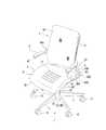
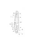
椅子は、図1〜図3に示すように、脚1と、該脚1に取り付けられた基台部2(図2及び図3参照)と、該基台部2上に配置された座3と、座3の後方から起立した背凭れ4であって、前後方向における起立位置と傾動位置との間で傾動可能に設けられた背凭れ4と、座3の左右両側の上方位置に配置された肘掛け5とを備える。  As shown in FIGS. 1 to 3, the chair includes aleg 1, a base part 2 (see FIGS. 2 and 3) attached to theleg 1, and aseat 3 disposed on thebase part 2. And abackrest 4 erected from the rear of theseat 3, and thebackrest 4 provided so as to be tiltable between a standing position and a tilting position in the front-rear direction, and an upper position on both the left and right sides of theseat 3.Armrest 5.

かかる椅子は、背凭れ4が傾動可能に設けられるに伴って種々の機構を備える。すなわち、椅子は、図3〜図5に示す如く、背凭れ4の後傾動作と座3の動作を連動させるシンクロロッキング機構6を備える。また、椅子は、図6及び図7に示す如く、後傾した背凭れ4を起立位置に戻す反力を発生させる反力発生部材70を含む後傾反力発生機構7と、該反力発生部材70を予め変形させて背凭れ4を起立位置に戻す反力の大きさを変更する反力調整機構8とを備える。  Such a chair includes various mechanisms as thebackrest 4 is tiltably provided. That is, as shown in FIGS. 3 to 5, the chair includes a synchro-rockingmechanism 6 that interlocks the backward tilting operation of thebackrest 4 and the operation of theseat 3. Further, as shown in FIGS. 6 and 7, the chair includes a rearward reactionforce generation mechanism 7 including a reactionforce generation member 70 that generates a reaction force that returns thebackrest 4 tilted backward to the standing position, and the reaction force generation. And a reactionforce adjusting mechanism 8 that changes the magnitude of the reaction force that deforms themember 70 in advance to return thebackrest 4 to the upright position.

図1〜図3に戻り、脚1は、脚支柱10と、脚支柱10から放射状に突出した複数の脚羽根11,…とを備える。本実施形態において、脚1は、複数の脚羽根11,…の先端に取り付けられたキャスタ12,…を備える。  1 to 3, theleg 1 includes aleg column 10 and a plurality ofleg blades 11 that protrude radially from theleg column 10. In the present embodiment, theleg 1 includescasters 12,... Attached to the tips of the plurality ofleg blades 11,.

脚支柱10は、図2及び図3に示す如く、筒状の支柱本体13と、支柱本体13に内挿されたガススプリング14であって、座3を昇降させるガススプリング14とを備える。支柱本体13は、両端開口を上下に位置させている。これに伴い、複数の脚羽根11,…は、支柱本体13の外周面から延出し、平面視放射状に配置されている。  As shown in FIGS. 2 and 3, theleg column 10 includes a cylindrical columnmain body 13 and agas spring 14 inserted in the columnmain body 13 and moving up and down theseat 3. The columnmain body 13 has both end openings positioned vertically. Accordingly, the plurality ofleg blades 11,... Extend from the outer peripheral surface of the columnmain body 13 and are arranged radially in plan view.

ガススプリング14は、支柱本体13内に配置されるシリンダ140と、軸線方向に移動可能に設けられたピストンロッド141とを備える。シリンダ140には、ガスが封入されている。ピストンロッド141は、軸線方向に移動可能に設けられたもので、シリンダ140内に配置されるピストン(図示しない)であって、シリンダ140の内部空間を二つの部屋に区画するピストンと、一端がシリンダ140内でピストンに連結される一方、他端側がシリンダ140の外側に突出した棒状のロッド142とを備える。  Thegas spring 14 includes acylinder 140 disposed in the columnmain body 13 and apiston rod 141 provided to be movable in the axial direction. Gas is sealed in thecylinder 140. Thepiston rod 141 is provided so as to be movable in the axial direction. Thepiston rod 141 is a piston (not shown) disposed in thecylinder 140. Thepiston rod 141 divides the internal space of thecylinder 140 into two chambers, and one end thereof. A rod-shapedrod 142 is connected to the piston in thecylinder 140 and the other end protrudes to the outside of thecylinder 140.

ガススプリング14は、ピストンによって区画された二つの部屋でガスを行き来させることで、ピストンロッド141が軸線方向に移動し、全体的に伸縮するようになっている。本実施形態において、ガススプリング14は、常態において、二つの部屋間でのガスの行き来を阻止し、ピストンロッド141の移動を規制(ロック)するようになっている。これに伴い、ガススプリング14は、図3に示す如く、ロッド142の他端に突出して設けられたロック解除ボタン143を備え、ロック解除ボタン143をロッド142内に押し込むことで、ピストンロッド141の移動の規制を解除できるようになっている。ロック解除ボタン143は、肘掛け5に設けられた後述のロック解除レバー92により操作される。  Thegas spring 14 moves thepiston rod 141 in the axial direction by moving gas back and forth in two chambers partitioned by the piston, so that thegas spring 14 extends and contracts as a whole. In the present embodiment, thegas spring 14 normally prevents gas from passing between the two rooms and restricts (locks) the movement of thepiston rod 141. Accordingly, as shown in FIG. 3, thegas spring 14 includes alock release button 143 that protrudes from the other end of therod 142, and pushes thelock release button 143 into therod 142. The restriction on movement can be released. Thelock release button 143 is operated by alock release lever 92 described later provided on thearmrest 5.

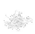
基台部2は、アルミダイキャスト等による成型品である。基台部2は、図4〜図6に示すように、脚支柱10のロッド142に嵌着されるボス部20(図6参照)と、該ボス部20の上端に連結された第一フレーム部21であって、ボス部20を囲う平面視半円弧状の第一フレーム部21と、第一フレーム部21の両端から前方に延出する一対の第二フレーム部22,22と、一対の第二フレーム部22,22の前端部同士を連結した第三フレーム部23と、第三フレーム部23の上面に設けられた第一軸支部24であって、後述する第一軸60を支持する第一軸支部24と、第一フレーム部21と第二フレーム部22,22との境界付近に設けられた第二軸支部25であって、後述する第二軸61を支持する第二軸支部25とを備える。  Thebase part 2 is a molded product by aluminum die casting or the like. As shown in FIGS. 4 to 6, thebase portion 2 includes a boss portion 20 (see FIG. 6) fitted to therod 142 of theleg column 10, and a first frame connected to the upper end of theboss portion 20. Afirst frame part 21 having a semicircular arc shape in plan view surrounding theboss part 20; a pair ofsecond frame parts 22 and 22 extending forward from both ends of thefirst frame part 21; Thethird frame portion 23 that connects the front end portions of thesecond frame portions 22 and 22, and the firstshaft support portion 24 provided on the upper surface of thethird frame portion 23, which supports afirst shaft 60 described later. A secondshaft support portion 25 provided near the boundary between the firstshaft support portion 24, thefirst frame portion 21 and thesecond frame portions 22, 22, and supports asecond shaft 61 described later. 25.

基台部2は、第三フレーム部23が第一フレーム部21よりも当該椅子の前後方向の前側(前方)に位置するように配置される。第一軸支部24及び第二軸支部25は、上下方向において異なる位置に配置されている。本実施形態において、前側の第一軸支部24が後側の第二軸支部25よりも高い位置に配置されている。  Thebase part 2 is arranged so that thethird frame part 23 is located on the front side (front side) of the chair in the front-rear direction with respect to thefirst frame part 21. The firstshaft support portion 24 and the secondshaft support portion 25 are arranged at different positions in the vertical direction. In the present embodiment, thefirst shaft support 24 on the front side is disposed at a position higher than thesecond shaft support 25 on the rear side.

座3は、図2に示す如く、基台部2の上方に配置される座受部30と、座受部30の上面に重ね合わされる座本体部31とを備える。  As shown in FIG. 2, theseat 3 includes aseat receiving portion 30 disposed above thebase portion 2, and a seatmain body portion 31 superimposed on the upper surface of theseat receiving portion 30.

座受部30は、アウターシェルと称し得る形態を有し、合成樹脂により一体に成型されている。座受部30は、後述する第三軸62を軸支する第三軸支部32であって、下面に設けられた第三軸支部32と、後述する第四軸63を軸支する第四軸支部33であって、下面に設けられた第四軸支部33とを備える。  Theseat receiving portion 30 has a form that can be referred to as an outer shell, and is integrally formed of synthetic resin. Theseat receiving portion 30 is a thirdshaft support portion 32 that supports athird shaft 62 described later, and a fourth shaft that supports a thirdshaft support portion 32 provided on the lower surface and afourth shaft 63 described later. It is thesupport part 33, Comprising: The 4thaxial support part 33 provided in the lower surface is provided.

第三軸支部32は、当該座受部30の前端側に配置され、第四軸支部33は、第三軸支部32よりも後端側に配置される。本実施形態において、第四軸支部33は、座受部30の略中央に配置されている。  The thirdshaft support portion 32 is disposed on the front end side of theseat receiving portion 30, and the fourthshaft support portion 33 is disposed on the rear end side of the thirdshaft support portion 32. In the present embodiment, the fourthshaft support portion 33 is disposed substantially at the center of theseat receiving portion 30.

座本体部31は、図3に示す如く、座受部30の上面に取り付けられたインナーシェル(図示しない)と、該インナーシェル上に配されたクッション34と、該クッション34の外面に張られた座用張地35とを備える。  As shown in FIG. 3, the seatmain body 31 is stretched on an inner shell (not shown) attached to the upper surface of theseat receiving portion 30, acushion 34 disposed on the inner shell, and an outer surface of thecushion 34. And aseat tension material 35.

インナーシェルは、合成樹脂により一体に成型されている。クッション34は、発泡ウレタン等により形成されている。クッション34の上面には、前後方向に並ぶ複数本の溝36,…が設けられている。  The inner shell is integrally formed of synthetic resin. Thecushion 34 is formed of foamed urethane or the like. A plurality ofgrooves 36 arranged in the front-rear direction are provided on the upper surface of thecushion 34.

座用張地35は、袋状に形成され、クッション34を被覆可能に構成される。座用張地35には、クッション34に形成された溝36に対応した複数の線状37が形成されている。複数の線状37は、エンボス加工により形成されたもので、座用張地35でクッション34を被覆した状態で、クッション34の溝36に上方から重なり合うように形成されている。  Theseat tension fabric 35 is formed in a bag shape and configured to cover thecushion 34. A plurality oflinear shapes 37 corresponding to thegrooves 36 formed in thecushion 34 are formed in theseat tension fabric 35. The plurality oflinear lines 37 are formed by embossing, and are formed so as to overlap thegrooves 36 of thecushion 34 from above in a state where thecushion 34 is covered with theseat tension fabric 35.

背凭れ4は、樹脂製の背シェル40と、該背シェル40を支持する背支持部材41と、背シェル40の表面側に張られた背凭れ用張地42とを備える。  Thebackrest 4 includes a resin-madeback shell 40, aback support member 41 that supports theback shell 40, and abackrest tension fabric 42 that is stretched on the surface side of theback shell 40.

背シェル40は、左右方向に湾曲し、背凭れ面を形成している。本実施形態において、背シェル40は、前方側に配置されるシェル本体400と、シェル本体400の上端に連続した折り返し部401であって、シェル本体400の後方側に湾曲した折り返し部401と、折り返し部401と連続した垂下部402であって、シェル本体400と間隔をあけて配置された垂下部402とを備える。  Theback shell 40 is curved in the left-right direction to form a backrest surface. In the present embodiment, theback shell 40 includes ashell body 400 disposed on the front side, a foldedportion 401 that is continuous with the upper end of theshell body 400, and a foldedportion 401 that is curved toward the rear side of theshell body 400. A droopingportion 402 that is continuous with the foldedportion 401 and includes a droopingportion 402 that is spaced apart from theshell body 400.

背シェル40は、上下方向に延びるスリット状の開口部403であって、左右方向に間隔をあけて配置された複数の開口部403を有する。本実施形態において、複数の開口部403のそれぞれは、シェル本体400から垂下部402にかけて形成されている。これらの複数の開口部403は、背シェル40の弾性変形を助長させ、背凭れ4(背シェル40)のクッション性を向上させる。  Theback shell 40 is a slit-like opening 403 extending in the up-down direction, and has a plurality ofopenings 403 arranged at intervals in the left-right direction. In the present embodiment, each of the plurality ofopenings 403 is formed from theshell body 400 to the hangingportion 402. The plurality ofopenings 403 promotes elastic deformation of theback shell 40 and improves cushioning of the backrest 4 (back shell 40).

背支持部材41は、シェル本体400の後方に配置される。背支持部材41の上端部は、背シェル40における垂下部402の下端部に連結されている(図2参照)。背支持部材41は、上下方向に伸びる複数のリブ404であって、左右横並びに配置された複数のリブ404を有する。これにより、背支持部材41は、柔軟な背シェル40を剛性的に支持している。  Theback support member 41 is disposed behind theshell body 400. The upper end portion of theback support member 41 is connected to the lower end portion of the hangingportion 402 of the back shell 40 (see FIG. 2). Theback support member 41 has a plurality ofribs 404 extending in the vertical direction, and has a plurality ofribs 404 arranged side by side. Thereby, theback support member 41 rigidly supports theflexible back shell 40.

背凭れ用張地42は、通気性及び透光性を有した布材を主体に構成され、背シェル40のほぼ全域を覆い隠せるように寸法設定及び形状設定されている。  Thebackrest tension fabric 42 is mainly composed of a breathable and translucent cloth material, and is sized and shaped so as to cover almost the entire area of theback shell 40.

背凭れ4は、上述の如く、前後方向に傾動可能に設けられる。これに伴い、本実施形態に係る椅子は、背凭れ4を支持する背凭れ支持体43であって、基台部2に回転可能に連結される背凭れ支持体43を備える。  As described above, thebackrest 4 is provided so as to be tiltable in the front-rear direction. Accordingly, the chair according to this embodiment includes abackrest support body 43 that supports thebackrest 4 and is rotatably connected to thebase portion 2.

背凭れ支持体43は、基台部2から後上方に延出させた左右一対の背支持アーム430,430と、一対の背支持アーム430,430の上端部431,431同士を連結する上連結材432と、各背支持アーム430の基端部内側面に沿って配置される一対の背支持ブラケット433,433であって、第二軸61を介して基台部2に回転自在に取り付けられた一対の背支持ブラケット433,433と、一対の背支持ブラケット433,433同士を連結する下連結材434とを備える。  Thebackrest support body 43 is an upper connection that connects a pair of left and rightback support arms 430 and 430 extending rearward and upward from thebase portion 2 andupper ends 431 and 431 of the pair ofback support arms 430 and 430. A pair ofback support brackets 433 and 433 disposed along the inner surface of the base end portion of each of thematerial 432 and theback support arms 430, and rotatably attached to thebase portion 2 via thesecond shaft 61. A pair ofback support brackets 433 and 433 and a lower connectingmember 434 that connects the pair ofback support brackets 433 and 433 to each other are provided.

一対の背支持アーム430,430のそれぞれは、樹脂成型品であり、基台部2に回動可能に支持されている。より具体的には、一対の背支持アーム430,430のそれぞれは、前後方向に延びる前後方向延出部435と、前後方向延出部435の後端から連続して上方に伸びる起立部436とを備える。  Each of the pair ofback support arms 430 and 430 is a resin molded product and is rotatably supported by thebase unit 2. More specifically, each of the pair ofback support arms 430 and 430 includes a front-reardirection extending portion 435 extending in the front-rear direction, and anupright portion 436 extending continuously upward from the rear end of the front-reardirection extending portion 435. Is provided.

各背支持アーム430は、前後方向延出部435の前端部に設けられた軸装部437であって、基台部2に支持された第二軸61の端部に外側から嵌め合わされる軸装部437を備える。背支持アーム430,430は、起立部436の上端部に上連結材432を取り付けるためのアーム突出部438を有する。これに伴い、上連結材432の両端部は、左右両側にある一対の背支持アーム430,430のアーム突出部438に重ね合わされ、該アーム突出部438にねじ(図示しない)を介して固定されている。  Eachback support arm 430 is ashaft mounting portion 437 provided at the front end portion of the front-reardirection extending portion 435 and is a shaft fitted from the outside to the end portion of thesecond shaft 61 supported by thebase portion 2. A mountingportion 437 is provided. Theback support arms 430 and 430 have anarm protrusion 438 for attaching the upper connectingmember 432 to the upper end portion of theupright portion 436. Accordingly, both ends of the upper connectingmember 432 are overlapped with thearm protrusions 438 of the pair ofback support arms 430 and 430 on the left and right sides, and are fixed to thearm protrusions 438 via screws (not shown). ing.

軸装部437は、図4及び図5に示すように、第二軸61の端部を嵌合させるべく内方にのみ開口させた軸穴439を有する。具体的には、第二軸61の端部及び軸穴439は、ブッシュ441を介して相対回転可能に嵌合されている。  As shown in FIGS. 4 and 5, theshaft mounting portion 437 has ashaft hole 439 that is opened only inward to fit the end portion of thesecond shaft 61. Specifically, the end of thesecond shaft 61 and theshaft hole 439 are fitted via abush 441 so as to be relatively rotatable.

各背支持アーム430,430は、下連結材434に重ね合わされるカバー部440であって、軸装部437の近傍から相手方の背支持アーム430に向けて延出したカバー部440を備える。カバー部440は、ねじ(図示しない)を介して下連結材434に固定されている。  Each of theback support arms 430 and 430 is acover portion 440 that is superimposed on the lower connectingmember 434 and includes acover portion 440 that extends from the vicinity of theshaft mounting portion 437 toward the counterpart backsupport arm 430. Thecover part 440 is fixed to the lower connectingmember 434 via a screw (not shown).

一対の背支持ブラケット433,433のそれぞれは、第二軸61を介して基台部2に回動可能に支持されている。より具体的には、一対の背支持ブラケット433,433は、基台部2(第一フレーム部21)を挟んで配置される。一対の背支持ブラケット433,433は、基端と先端とを有するアーム状に形成され、基端部が基台部2の第二軸支部25に支持された第二軸61に回転自在に支持されている。  Each of the pair ofback support brackets 433 and 433 is rotatably supported by thebase portion 2 via thesecond shaft 61. More specifically, the pair ofback support brackets 433 and 433 are arranged with the base portion 2 (first frame portion 21) interposed therebetween. The pair ofback support brackets 433 and 433 are formed in an arm shape having a base end and a tip end, and the base end portion is rotatably supported by thesecond shaft 61 supported by the secondshaft support portion 25 of thebase portion 2. Has been.

下連結材434は、一対の背支持ブラケット433,433に跨るように配置されている。すなわち、下連結材434の両端部は、一対の背支持ブラケット433,433に連結されている。そして、上述の如く、下連結材434がカバー部440に固定されることで、一対の背支持ブラケット433,433は、背支持アーム430に連結された状態になっている。  The lower connectingmember 434 is disposed so as to straddle the pair ofback support brackets 433 and 433. That is, both ends of the lower connectingmember 434 are connected to the pair ofback support brackets 433 and 433. As described above, the lower connectingmember 434 is fixed to thecover portion 440, so that the pair ofback support brackets 433 and 433 are connected to theback support arm 430.

これにより、下連結材434及び背支持ブラケット433,433は、合成樹脂製の背支持アーム430,430とともに、背凭れ支持体43の骨格として機能する。本実施形態に係る背凭れ支持体43は、上連結材432によって背シェル40を支持し、着座者の体重の作用による背シェル40の前後方向へのたわみを制御する。  Accordingly, the lower connectingmember 434 and theback support brackets 433 and 433 function as a skeleton of thebackrest support body 43 together with theback support arms 430 and 430 made of synthetic resin. Thebackrest support body 43 according to the present embodiment supports theback shell 40 by the upper connectingmember 432 and controls theback shell 40 bending in the front-rear direction due to the action of the weight of the seated person.

肘掛け5は、図1〜図3に示す如く、左右一対の背支持アーム430,430のそれぞれに連設され、背支持アーム430から前方に向けて延出するように設けられている。本実施形態において、肘掛け5は、背支持アーム430と一体的に形成されている。これにより、椅子は、座3の左右両側の上方位置に一対の肘掛け5,5を有する。  As shown in FIGS. 1 to 3, thearmrest 5 is connected to each of the left and right pair ofback support arms 430 and 430 and is provided so as to extend forward from theback support arm 430. In the present embodiment, thearmrest 5 is formed integrally with theback support arm 430. Thereby, the chair has a pair ofarmrests 5 and 5 at the upper positions on both the left and right sides of theseat 3.

上述の如く、本実施形態に係る椅子は、図3に示す如く、座3を昇降させるガススプリング14であって、ロッド142の移動(座3の昇降)の規制を解除するロック解除ボタン143を有するガススプリング14を備える。これに伴い、椅子は、ロック解除ボタン143を遠隔操作するためのロック解除装置9を備える。  As described above, the chair according to the present embodiment is agas spring 14 that raises and lowers theseat 3 as shown in FIG. 3, and includes alock release button 143 that releases the restriction on the movement of the rod 142 (up and down of the seat 3). Agas spring 14 is provided. Accordingly, the chair includes alock release device 9 for remotely operating thelock release button 143.

ロック解除装置9は、図4、図5、及び図7に示す如く、ロック解除ボタン143を押圧するための押圧部90を有する解除アーム91と、肘掛け5に設けられたロック解除レバー92であって、引き操作可能に設けられたロック解除レバー92(図1及び図2参照)と、解除アーム91とロック解除レバー92とを作動的に接続する操作線93とを備える。  As shown in FIGS. 4, 5, and 7, thelock release device 9 includes arelease arm 91 having apressing portion 90 for pressing thelock release button 143 and alock release lever 92 provided on thearmrest 5. In addition, a lock release lever 92 (see FIGS. 1 and 2) provided so as to be capable of being pulled, and anoperation line 93 operatively connecting therelease arm 91 and thelock release lever 92 are provided.

解除アーム91は、先端と基端とを有し、先端側に押圧部90を有する。解除アーム91の基端部は、第二軸61に軸支されている。ロック解除レバー92は、座3の左右両側に設けられた一対の肘掛け5,5のうちの一方の肘掛け(本実施形態においては右側の肘掛け)5に装備されている(図1及び図2参照)。ロック解除レバー92は、先端と基端とを有し、基端側を支点にして回動可能に設けられている。  Therelease arm 91 has a distal end and a proximal end, and has apressing portion 90 on the distal end side. A base end portion of therelease arm 91 is pivotally supported by thesecond shaft 61. Thelock release lever 92 is mounted on one armrest (in the present embodiment, the right armrest) 5 of a pair ofarmrests 5 and 5 provided on the left and right sides of the seat 3 (see FIGS. 1 and 2). ). Thelock release lever 92 has a distal end and a proximal end, and is provided so as to be rotatable about the proximal end side as a fulcrum.

操作線93は、引っ張り力を伝達可能な線材であり、本実施形態では、ワイヤが採用されている。操作線93は、ロック解除レバー92と基台部2との間に敷設され、一端がロック解除レバー92に接続される一方、他端側が解除アーム91に接続されている。本実施形態において、操作線(ワイヤ)93は、管状のスリーブS1に挿通されている。スリーブS1は、操作線93と同様に、ロック解除レバー92と基台部2との間に敷設され、一端がロック解除レバー92の近傍に固定され、他端側が解除アーム91の近傍に固定されている。これに伴い、操作線93は、スリーブS1に案内されつつ長手方向に往復移動可能に設けられている。  Theoperation line 93 is a wire that can transmit a tensile force, and a wire is employed in the present embodiment. Theoperation line 93 is laid between thelock release lever 92 and thebase portion 2, and one end is connected to thelock release lever 92, while the other end side is connected to therelease arm 91. In the present embodiment, the operation line (wire) 93 is inserted through the tubular sleeve S1. Similarly to theoperation line 93, the sleeve S1 is laid between thelock release lever 92 and thebase portion 2, one end is fixed near thelock release lever 92, and the other end side is fixed near therelease arm 91. ing. Accordingly, theoperation line 93 is provided so as to be reciprocally movable in the longitudinal direction while being guided by the sleeve S1.

これにより、ロック解除装置9は、ロック解除レバー92の操作力を解除アーム91に伝達し、第二軸61を支点に解除アーム91を回転させるようになっている。すなわち、ロック解除装置9は、ロック解除レバー92による遠隔操作により、押圧部90がロック解除ボタン143を押圧する状態と押圧部90によるロック解除ボタン143に対する押圧を解除した状態とに切り替え可能に構成されている。  Thereby, thelock release device 9 transmits the operating force of thelock release lever 92 to therelease arm 91, and rotates therelease arm 91 about thesecond shaft 61 as a fulcrum. That is, thelock release device 9 is configured to be switchable between a state in which thepressing portion 90 presses thelock release button 143 and a state in which the press on thelock release button 143 by thepressing portion 90 is released by remote operation by thelock release lever 92. Has been.

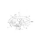
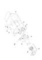
シンクロロッキング機構6は、図2に示す如く、リンク機構であり、基台部2の第一軸支部24に支持された第一軸60と、基台部2の第二軸支部25に支持された第二軸61と、座3の第三軸支部32に支持された第三軸62と、座3の第四軸支部33に支持された第四軸63と、第一軸60と第三軸62とに連結された第一リンク64,64と、第二軸61と第四軸63とに連結された第二リンク65,65とを備える。  As shown in FIG. 2, the synchro-rockingmechanism 6 is a link mechanism, and is supported by thefirst shaft 60 supported by the firstshaft support portion 24 of thebase portion 2 and the secondshaft support portion 25 of thebase portion 2. Thesecond shaft 61, thethird shaft 62 supported by the thirdshaft support portion 32 of theseat 3, thefourth shaft 63 supported by the fourthshaft support portion 33 of theseat 3, thefirst shaft 60 and the third shaft First links 64 and 64 connected to theshaft 62 andsecond links 65 and 65 connected to thesecond shaft 61 and thefourth shaft 63 are provided.

第一軸60、第二軸61、第三軸62、及び第四軸63のそれぞれは、左右横方向に延びている。第一軸60は、第一軸支部24に自己の軸心周りで回転自在に支持されている。第二軸61は、第二軸支部25に固定されている。第三軸62は、第三軸支部32に自己の軸心周りで回転自在に支持されている。第四軸63は、第四軸支部33に固定されている。  Each of thefirst shaft 60, thesecond shaft 61, thethird shaft 62, and thefourth shaft 63 extends in the horizontal direction. Thefirst shaft 60 is supported by thefirst shaft support 24 so as to be rotatable around its own axis. Thesecond shaft 61 is fixed to the secondshaft support portion 25. Thethird shaft 62 is supported by thethird shaft support 32 so as to be rotatable around its own axis. Thefourth shaft 63 is fixed to the fourthshaft support portion 33.

第一リンク64,64は、図4及び図5に示す如く、左右幅方向に間隔をあけて二つ設けられている。一方の第一リンク64は、第一軸60の一端部と第三軸62の一端部とに連結され、他方の第一リンク64は、第一軸60の他端部と第三軸62の他端部とに連結されている。第一リンク64,64は、第一軸60及び第三軸62のそれぞれを支点に傾倒可能に設けられている。本実施形態において、第一軸60及び第三軸62の支持態様が上述の通りであるため、第一リンク64は、第一軸60に回転不能に連結される一方、第三軸62に回転自在に連結されている。  As shown in FIGS. 4 and 5, thefirst links 64 and 64 are provided with two spaces in the left-right width direction. Onefirst link 64 is connected to one end of thefirst shaft 60 and one end of thethird shaft 62, and the otherfirst link 64 is connected to the other end of thefirst shaft 60 and thethird shaft 62. It is connected to the other end. Thefirst links 64 and 64 are provided so as to be tiltable about thefirst shaft 60 and thethird shaft 62 as fulcrums. In the present embodiment, since the support mode of thefirst shaft 60 and thethird shaft 62 is as described above, thefirst link 64 is non-rotatably connected to thefirst shaft 60 while rotating to thethird shaft 62. It is connected freely.

第二リンク65,65は、左右幅方向に間隔をあけて二つ設けられている。一方の第二リンク65は、第二軸61の一端部と第四軸63の一端部とに連結され、他方の第二リンク65は、第二軸61の他端部と第四軸63の他端部とに連結されている。第二リンク65,65は、第二軸61及び第四軸63のそれぞれを支点に傾倒可能に設けられている。  Twosecond links 65, 65 are provided at intervals in the left-right width direction. Onesecond link 65 is connected to one end of thesecond shaft 61 and one end of thefourth shaft 63, and the othersecond link 65 is connected to the other end of thesecond shaft 61 and thefourth shaft 63. It is connected to the other end. Thesecond links 65 and 65 are provided so as to be tiltable about thesecond shaft 61 and thefourth shaft 63 as fulcrums.

本実施形態において、第二軸61及び第四軸63の支持態様が上述の通りであるため、第二リンク65は、第二軸61に回転自在に連結される一方、第四軸63に回転自在に連結されている。本実施形態において、背支持アーム430が第二軸61に回転自在に連結されているため、第二リンク65は、背支持アーム430と一体的に形成されている。すなわち、第二リンク65は、背支持アーム430の軸装部437の外面から延出している。これにより、背支持アーム430及び第二リンク65は、共通した軸周りで回転可能に設けられている。  In the present embodiment, since the support mode of thesecond shaft 61 and thefourth shaft 63 is as described above, thesecond link 65 is rotatably connected to thesecond shaft 61, while rotating to thefourth shaft 63. It is connected freely. In the present embodiment, since theback support arm 430 is rotatably connected to thesecond shaft 61, thesecond link 65 is formed integrally with theback support arm 430. That is, thesecond link 65 extends from the outer surface of theshaft mounting portion 437 of theback support arm 430. Thereby, theback support arm 430 and thesecond link 65 are provided to be rotatable around a common axis.

シンクロロッキング機構6は、図8に示す如く、第一リンク64及び第二リンク65の傾動により、第一リンク64及び第二リンク65に支持された座3を昇降させる。本実施形態において、上述の如く、第二リンク65が背支持アーム430と一体的に形成されているため、背凭れ4に着座者の体重が作用して背凭れ4が後傾動作するに伴い、座3を上昇させる一方、着座者の姿勢変更等で座3に着座者の体重が作用して座3が下降するに伴い、背凭れ4を起立させるようになっている。  As shown in FIG. 8, the synchro-rockingmechanism 6 moves theseat 3 supported by thefirst link 64 and thesecond link 65 up and down by tilting thefirst link 64 and thesecond link 65. In the present embodiment, as described above, since thesecond link 65 is formed integrally with theback support arm 430, the weight of the seated person acts on thebackrest 4 and thebackrest 4 moves backward. While theseat 3 is raised, thebackrest 4 is erected as theseat 3 descends due to the weight of the seat occupant acting on theseat 3 due to the posture change of the seat occupant.

本実施形態に係る椅子において、第一リンク64の有効長さ寸法(第一軸60と第三軸62との軸心間距離)L1と、第二リンク65の有効長さ寸法(第二軸61と第四軸63との軸心間距離)L2とは、同寸法になっている。第一リンク64及び第二リンク65のそれぞれは、これらを介して連結された座3と基台部2とが最も接近した状態(座3が最下降位置にある状態)で、前傾姿勢となるように設けられている。そして、この状態において、第一リンク64の前傾度合いが第二リンク65の前傾度合いよりも大きくなるようになっている。すなわち、本実施形態に係る椅子は、上述の如く、背支持アーム430が第二軸61に回転自在に連結されているため、背凭れ4を後傾させていない状態において、第一リンク64の水平線に対する傾斜角度αが第二リンク65の水平線に対する傾斜角度βよりも小さくなっている。  In the chair according to the present embodiment, the effective length dimension of the first link 64 (distance between the center axes of thefirst shaft 60 and the third shaft 62) L1 and the effective length dimension of the second link 65 (second shaft). The distance L2 between the axes of 61 and thefourth shaft 63 is the same. Each of thefirst link 64 and thesecond link 65 has a forward tilt posture in a state where theseat 3 and thebase portion 2 connected via these are closest (state where theseat 3 is in the lowest position). It is provided to become. In this state, the forward inclination degree of thefirst link 64 is larger than the forward inclination degree of thesecond link 65. That is, in the chair according to the present embodiment, since theback support arm 430 is rotatably connected to thesecond shaft 61 as described above, in the state where thebackrest 4 is not tilted backward, The inclination angle α with respect to the horizontal line is smaller than the inclination angle β with respect to the horizontal line of thesecond link 65.

また、第一リンク64の基台部2に対する回転中心が第二リンク65の基台部2に対する回転中心よりも高い位置になっている。換言すれば、第一軸60の軸心が第二軸61の軸心よりも距離h分高い位置になっている。また、背支持アーム430が基台部2における脚支柱10よりも前側の部位に枢支されている。換言すれば、背支持アーム430の軸装部437が側面視において脚支柱10よりも前側に位置する第二軸61に支持されている。これにより、シンクロロッキング機構6は、背凭れ4の後傾動作によって、座3の前部が持ち上がる寸法γ1は、座3の後部が持ち上がる寸法γ2よりも多くなっている。  Further, the center of rotation of thefirst link 64 relative to thebase 2 is higher than the center of rotation of thesecond link 65 relative to thebase 2. In other words, the axis of thefirst shaft 60 is higher than the axis of thesecond shaft 61 by the distance h. Further, theback support arm 430 is pivotally supported at a position on the front side of theleg column 10 in thebase portion 2. In other words, theshaft mounting portion 437 of theback support arm 430 is supported by thesecond shaft 61 positioned on the front side of theleg support 10 in a side view. Thus, in the synchro-rockingmechanism 6, the dimension γ <b> 1 that the front part of theseat 3 is lifted by the backward tilting operation of thebackrest 4 is larger than the dimension γ <b> 2 that the rear part of theseat 3 is lifted.

このように、本実施形態に係るシンクロロッキング機構6は、着座者の体重の作用で座3を上昇及び下降させる体重感知式であり、背凭れの後傾動作に伴わせて座を傾動させる通常のシンクロロッキング機構とは異なり、図8に二点鎖線で示すように、背凭れ4の後傾動作に伴わせて座3を傾動させつつ着座者の体重に抗して座3を持ち上げるように構成されている。  As described above, the synchro-rockingmechanism 6 according to the present embodiment is a weight sensing type that raises and lowers theseat 3 by the action of the body weight of the seated person, and normally tilts the seat in accordance with the back tilting operation of the backrest. Unlike the synchro-rocking mechanism of FIG. 8, as shown by a two-dot chain line in FIG. 8, theseat 3 is lifted against the weight of the seated person while tilting theseat 3 in accordance with the backward tilting motion of thebackrest 4. It is configured.

後傾反力発生機構7は、上述の如く、反力発生部材70を含む。本実施形態において、反力発生部材70は、コイルバネである。これに伴い、後傾反力発生機構7は、図9に示す如く、コイルバネ(反力発生部材)70の両端を受ける一対のバネ受部材71,72と、一対のバネ受部材71,72を接離可能に連結する連結ガイド機構73とを備える。  The rearward tiltingforce generating mechanism 7 includes the reactionforce generating member 70 as described above. In the present embodiment, the reactionforce generation member 70 is a coil spring. Accordingly, as shown in FIG. 9, the rearward reactionforce generating mechanism 7 includes a pair ofspring receiving members 71 and 72 that receive both ends of a coil spring (reaction force generating member) 70, and a pair ofspring receiving members 71 and 72. And acoupling guide mechanism 73 coupled so as to be able to come into and out of contact.

後傾反力発生機構7は、基台部2の下方に配置される。一方のバネ受部材(以下、第一バネ受部材という)71は、前後方向に移動可能に基台部2に支持される。より具体的に説明する。第一バネ受部材71は、コイルバネ70の一端を支持する第一バネ支持部710と、第一バネ支持部710の両側から延出した一対のガイド部711,711とを備える。第一バネ支持部710は、プレート状に形成され、一方の面でコイルバネ70の一端を支持する。一対のガイド部711,711は、第一バネ支持部710の左右両端から外方に延出している  The rear tiltingforce generation mechanism 7 is disposed below thebase unit 2. One spring receiving member (hereinafter referred to as a first spring receiving member) 71 is supported by thebase portion 2 so as to be movable in the front-rear direction. This will be described more specifically. The firstspring receiving member 71 includes a firstspring support portion 710 that supports one end of thecoil spring 70, and a pair ofguide portions 711 and 711 extending from both sides of the firstspring support portion 710. The firstspring support portion 710 is formed in a plate shape and supports one end of thecoil spring 70 on one surface. The pair ofguide portions 711 and 711 extend outward from the left and right ends of the firstspring support portion 710.

これに伴い、基台部2の第三フレーム部23は、第一バネ支持部710を前後方向で移動可能に収容する収容スペース26と、収容スペース26の両側にガイド部711を前後方向に案内する一対のガイド溝27,27とを有する。第一バネ受部材71は、第一バネ支持部710が収容スペース26内に配置されるとともに、ガイド部711,711がガイド溝27,27に配置される。これにより、第一バネ受部材71は、傾いたり回転したりすることなく前後方向に移動可能な状態で基台部2に支持されている。  Accordingly, thethird frame part 23 of thebase part 2 guides theguide part 711 in the front-rear direction on thestorage space 26 that houses the firstspring support part 710 so as to be movable in the front-rear direction. And a pair ofguide grooves 27, 27. In the firstspring receiving member 71, the firstspring support portion 710 is disposed in theaccommodation space 26, and theguide portions 711 and 711 are disposed in theguide grooves 27 and 27. Thereby, the 1stspring receiving member 71 is supported by thebase part 2 in the state which can move to the front-back direction, without tilting or rotating.

他方のバネ受部材(以下、第二バネ受部材という)72は、背凭れ4の骨格的な機能を果たす背支持ブラケット433,433に直接的又は間接的に連結される。  The other spring receiving member (hereinafter referred to as a second spring receiving member) 72 is directly or indirectly connected to theback support brackets 433 and 433 that perform the skeletal function of thebackrest 4.

より具体的に説明する。本実施形態において、後傾反力発生機構7は、図4及び図5に示す如く、背凭れ4の後傾動作に伴ってコイルバネ(反力発生部材70)70を押圧する押圧体74を備える。押圧体74は、一対の背支持ブラケット433,433のそれぞれから前方に延出した一対のアーム74a,74aと、左右横方向に延びる連結棒74bであって、一対のアーム74a,74a同士を連結した連結棒74bとを備える。  This will be described more specifically. In the present embodiment, the backward tilt reactionforce generation mechanism 7 includes apressing body 74 that presses the coil spring (reaction force generation member 70) 70 in accordance with the backward tilt operation of thebackrest 4 as shown in FIGS. . Thepressing body 74 is a pair ofarms 74a and 74a extending forward from each of the pair ofback support brackets 433 and 433 and a connectingrod 74b extending in the horizontal direction, and connects the pair ofarms 74a and 74a.Connecting rod 74b.

背支持ブラケット433とアーム74aとは、一体的に形成されており、第二軸61を共通の回転支点として回転可能になっている。連結棒74bは、第二軸61に対して間隔をあけて平行又は略平行に配置され、前方側にあるアーム74a,74aの先端部同士を連結している。  Theback support bracket 433 and thearm 74a are integrally formed, and can rotate with thesecond shaft 61 as a common rotation fulcrum. The connectingrod 74b is arranged in parallel or substantially in parallel with thesecond shaft 61, and connects the distal ends of thearms 74a and 74a on the front side.

これに伴い、第二バネ受部材72は、図9に示す如く、コイルバネ70の他端を支持する第二バネ支持部720と、連結棒74bに係止可能に形成された係止片721とを備える。第二バネ支持部720は、プレート状に形成され、一方の面(前側の面)でコイルバネ70の他端を支持する。これに伴い、係止片721は、第二バネ支持部720の他方の面(後側の面)から後方に延出している。本実施形態において、係止片721は、左右横方向に間隔をあけて二つ設けられている。係止片721のそれぞれは、連結棒74bを嵌合する切り欠き状の連結棒嵌合部722を有する。  Accordingly, as shown in FIG. 9, the secondspring receiving member 72 includes a secondspring support portion 720 that supports the other end of thecoil spring 70, and alocking piece 721 that can be locked to the connectingrod 74b. Is provided. The secondspring support portion 720 is formed in a plate shape and supports the other end of thecoil spring 70 on one surface (front surface). Accordingly, thelocking piece 721 extends rearward from the other surface (rear surface) of the secondspring support portion 720. In the present embodiment, two lockingpieces 721 are provided at intervals in the left-right lateral direction. Each of the lockingpieces 721 has a notch-like connecting rodfitting portion 722 that fits the connectingrod 74b.

これにより、第二バネ受部材72は、連結棒嵌合部722に連結棒74bを嵌合することで、押圧体74を介して背支持ブラケット433,433に連結される。  Accordingly, the secondspring receiving member 72 is coupled to theback support brackets 433 and 433 via thepressing body 74 by fitting thecoupling rod 74 b to the coupling rodfitting portion 722.

連結ガイド機構73は、第二バネ受部材72の第二バネ支持部720の他方の面に連結されたガイド体730と、第一バネ受部材71の第一バネ支持部710の他方の面に連結されたガイド棒731であって、第二バネ受部材72に向けて延出し、ガイド体730に軸心方向に移動可能に挿入されたガイド棒731とを備える。連結ガイド機構73は、コイルバネ70の内部に配置される。すなわち、連結ガイド機構73は、ガイド棒731がコイルバネ70と同心になるように設けられている。これにより、第一バネ受部材71及び第二バネ受部材72は、コイルバネ70が伸縮したときに、コイルバネ70の反発力を受けつつガイド棒731の軸線に沿って移動する。  Theconnection guide mechanism 73 is connected to the other surface of the firstspring support portion 710 of the firstspring support member 71 and theguide body 730 connected to the other surface of the secondspring support portion 720 of the secondspring support member 72. Theguide rod 731 is aguide rod 731 that extends toward the secondspring receiving member 72 and is inserted into theguide body 730 so as to be movable in the axial direction. Theconnection guide mechanism 73 is disposed inside thecoil spring 70. That is, theconnection guide mechanism 73 is provided so that theguide rod 731 is concentric with thecoil spring 70. Thereby, the firstspring receiving member 71 and the secondspring receiving member 72 move along the axis of theguide bar 731 while receiving the repulsive force of thecoil spring 70 when thecoil spring 70 expands and contracts.

上記構成の後傾反力発生機構7は、押圧体74を介してコイルバネ70の反発力を背凭れ4の後傾動作に対する反力として作用させる。すなわち、後傾反力発生機構7は、背凭れ4が後傾動作したときに、押圧体74がコイルバネ70を押圧し、その押圧によって生じるコイルバネ70の反発力を背凭れ4に対して作用させる。  The backward tiltingforce generating mechanism 7 having the above-described configuration causes the repulsive force of thecoil spring 70 to act as a reaction force against the backward tilting operation of thebackrest 4 via thepressing body 74. That is, when thebackrest 4 is tilted backward, the back tiltingforce generation mechanism 7 presses thecoil spring 70 by thepressing body 74 and causes the repulsive force of thecoil spring 70 generated by the pressing to act on thebackrest 4. .

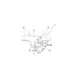
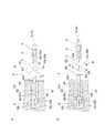
反力調整機構8は、図7に示す如く、所定の軸線周りで回転可能な回転カム800によって反力発生部材(コイルバネ)70に対して背凭れ4の起立位置において異なる大きさの初期変形を与えるものであり、操作部81(図1〜図3参照)から操作線83を介して回転カム800を回転させるように構成されている。  As shown in FIG. 7, the reactionforce adjusting mechanism 8 performs initial deformations of different sizes at the standing position of thebackrest 4 with respect to the reaction force generating member (coil spring) 70 by arotating cam 800 that can rotate around a predetermined axis. Therotary cam 800 is configured to rotate from the operation unit 81 (see FIGS. 1 to 3) via theoperation line 83.

より具体的に説明する。反力調整機構8は、所定の軸線周りで回転可能な回転カム800を含むカム機構80であって、回転カム800の回転に伴ってコイルバネ(反力発生部材)70に対して異なる力を加えるカム機構80と、着座者が操作可能な領域に配置された操作部81(図1〜図3参照)と、入力された直線力を回転力に変換して該回転力を回転カムに伝達する伝達機構82と、操作部81と伝達機構82とを接続し、操作部81に対する操作力を直線力として伝達機構82に伝達する操作線83とを備える。  This will be described more specifically. The reactionforce adjusting mechanism 8 is acam mechanism 80 including arotating cam 800 that can rotate around a predetermined axis, and applies different forces to the coil spring (reaction force generating member) 70 as the rotatingcam 800 rotates. Acam mechanism 80, an operation unit 81 (see FIGS. 1 to 3) disposed in a region where a seated person can operate, and an input linear force is converted into a rotational force and the rotational force is transmitted to the rotary cam. Thetransmission mechanism 82, theoperation part 81, and thetransmission mechanism 82 are connected, and theoperation line 83 which transmits the operation force with respect to theoperation part 81 to thetransmission mechanism 82 as a linear force is provided.

カム機構80は、図7及び図9に示す如く、回転カム800と、回転カム800の回転中心となる軸体801であって、基台部2に回転自在に支持される軸体801とを備える。  As shown in FIGS. 7 and 9, thecam mechanism 80 includes arotating cam 800 and ashaft body 801 that is a rotation center of therotating cam 800 and is rotatably supported by thebase portion 2. Prepare.

カム機構80は、後傾反力発生機構7に隣接して配置される。より具体的に説明する。回転カム800は、周面(外周面)の一部を第一バネ支持部710の他方の面に接触させている。軸体801は、回転カム800の回転中心位置を貫通している。そして、軸体801は、左右方向に延びるように配置され、両端部が基台部2に回転自在に支持されている。  Thecam mechanism 80 is arranged adjacent to the rearward reactionforce generation mechanism 7. This will be described more specifically. Therotating cam 800 has a part of the circumferential surface (outer circumferential surface) in contact with the other surface of the firstspring support portion 710. Theshaft body 801 passes through the rotational center position of therotary cam 800. Theshaft body 801 is disposed so as to extend in the left-right direction, and both end portions are rotatably supported by thebase portion 2.

具体的に説明すると、図10に示す如く、基台部2の第三フレーム部23は、回転カム800を収容可能なカム収容スペース28であって、収容スペース26の前方側で該収容スペース26と連続したカム収容スペース28と、カム収容スペース28の左右両側に設けられた軸受部29,29であって、軸体801を回転自在に支持する軸受部29,29とを有する。  Specifically, as shown in FIG. 10, thethird frame portion 23 of thebase portion 2 is acam accommodating space 28 that can accommodate therotating cam 800, and theaccommodating space 26 is located on the front side of theaccommodating space 26. And the bearingportions 29 and 29 provided on the left and right sides of thecam housing space 28, which support theshaft body 801 in a rotatable manner.

これに伴い、回転カム800がカム収容スペース28に配置された状態で、回転カム800を貫通した軸体80が軸受部29,29に回転可能に軸支されている。これにより、軸体801が基台部2(軸受部29,29)に支持され、コイルバネ70の反発力が回転カム800に作用したときに回転カム800が定位置で維持するようになっている。  Accordingly, theshaft body 80 penetrating therotating cam 800 is rotatably supported by the bearingportions 29 and 29 in a state where therotating cam 800 is disposed in thecam housing space 28. As a result, theshaft body 801 is supported by the base portion 2 (bearingportions 29, 29), and therotating cam 800 is maintained at a fixed position when the repulsive force of thecoil spring 70 acts on therotating cam 800. .

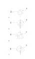
回転カム800は、図11に示す如く、回転中心CLからの距離D1,D2,D3,D4を周方向の異なる位置で異にする周面を有する。具体的には、回転カム800の周面は、周方向に間隔をあけて配置された四つのカム面C1,C2,C3,C4と、周方向に間隔をあけて配置された四つのロック面R1,R2,R3,R4であって、周方向で隣り合うカム面C1,C2,C3,C4同士を繋ぐ四つのロック面R1,R2,R3,R4とを有する。四つのカム面C1,C2,C3,C4のそれぞれは、湾曲凸面状に形成されている。四つのカム面C1,C2,C3,C4のそれぞれは、回転中心CLからの距離D1,D2,D3,D4が異なる。また、本実施形態において、四つのカム面C1,C2,C3,C4のそれぞれは、曲率中心及び曲率半径を異にする。四つのロック面R1,R2,R3,R4のそれぞれは、平面状に形成されている。  As shown in FIG. 11, the rotatingcam 800 has peripheral surfaces that make the distances D1, D2, D3, and D4 from the rotation center CL different at different positions in the circumferential direction. Specifically, the circumferential surface of therotating cam 800 includes four cam surfaces C1, C2, C3, and C4 that are spaced apart in the circumferential direction, and four lock surfaces that are spaced apart in the circumferential direction. R1, R2, R3, and R4, which have four lock surfaces R1, R2, R3, and R4 that connect cam surfaces C1, C2, C3, and C4 adjacent in the circumferential direction. Each of the four cam surfaces C1, C2, C3, C4 is formed in a curved convex shape. Each of the four cam surfaces C1, C2, C3, and C4 has different distances D1, D2, D3, and D4 from the rotation center CL. In the present embodiment, each of the four cam surfaces C1, C2, C3, and C4 has a different curvature center and curvature radius. Each of the four lock surfaces R1, R2, R3, R4 is formed in a planar shape.

本実施形態において、回転カム800は、カム面として、第一カム面C1と、第一カム面C1に対して周方向の一方側で隣り合う第二カム面C2と、第二カム面C2に対して周方向の一方側で隣り合う第三カム面C3と、第三カム面C3に対して周方向の一方側で隣り合うとともに、第一カム面C1に対して周方向の他方側で隣り合う第四カム面C4とを有する。第一カム面C1、第二カム面C2、第三カム面C3、第四カム面C4のそれぞれに対する回転中心CLからの距離D1,D2,D3,D4は、第一カム面C1、第二カム面C2、第三カム面C3、第四カム面C4の順(D1<D2<D3<D4)に長くなっている。  In the present embodiment, the rotatingcam 800 includes, as cam surfaces, a first cam surface C1, a second cam surface C2 that is adjacent to the first cam surface C1 on one side in the circumferential direction, and a second cam surface C2. The third cam surface C3 adjacent on one side in the circumferential direction is adjacent to the third cam surface C3 on one side in the circumferential direction, and is adjacent to the first cam surface C1 on the other side in the circumferential direction. And a matching fourth cam surface C4. The distances D1, D2, D3 and D4 from the rotation center CL with respect to each of the first cam surface C1, the second cam surface C2, the third cam surface C3 and the fourth cam surface C4 are the first cam surface C1 and the second cam surface C4. The length is increased in the order of the surface C2, the third cam surface C3, and the fourth cam surface C4 (D1 <D2 <D3 <D4).

これに伴い、第一カム面C1と第四カム面C4とを繋ぐロック面R4から回転中心CLまでの距離は、第一カム面C1と第二カム面C2とを繋ぐロック面R1から回転中心CLまでの距離よりも短く、且つ、第三カム面C3と第四カム面C4とを繋ぐロック面R3から回転中心CLまでの距離よりも短くなっている。また、第一カム面C1と第二カム面C2とを繋ぐロック面R1から回転中心CLまでの距離は、第二カム面C2と第三カム面C3とを繋ぐロック面R2から回転中心CLまでの距離よりも短く、第二カム面C2と第三カム面C3とを繋ぐロック面R2から回転中心CLまでの距離は、第三カム面C3と第四カム面C4とを繋ぐロック面R3から回転中心CLまでの距離よりも短くなっている。  Accordingly, the distance from the lock surface R4 connecting the first cam surface C1 and the fourth cam surface C4 to the rotation center CL is the rotation center from the lock surface R1 connecting the first cam surface C1 and the second cam surface C2. It is shorter than the distance to CL and shorter than the distance from the lock surface R3 connecting the third cam surface C3 and the fourth cam surface C4 to the rotation center CL. The distance from the lock surface R1 connecting the first cam surface C1 and the second cam surface C2 to the rotation center CL is from the lock surface R2 connecting the second cam surface C2 and the third cam surface C3 to the rotation center CL. The distance from the lock surface R2 connecting the second cam surface C2 and the third cam surface C3 to the center of rotation CL is shorter than the distance from the lock surface R3 connecting the third cam surface C3 and the fourth cam surface C4. It is shorter than the distance to the rotation center CL.

従って、図12(a)〜図12(c)に示す如く、回転カム800が周方向に回転し、第一バネ受部材71と密接するカム面C1,C2,C3,C4又はロック面R1,R2,R3,R4が変更する度に、回転カム800による後傾反力発生機構7の押し込み量が変化する。  Accordingly, as shown in FIGS. 12A to 12C, the cam surface C1, C2, C3, C4 or the lock surface R1, in which therotating cam 800 rotates in the circumferential direction and is in close contact with the firstspring receiving member 71, is provided. Each time R2, R3, and R4 change, the amount of pushing of the backward tiltforce generation mechanism 7 by the rotatingcam 800 changes.

これにより、回転カム800が移動することで、回転カム800の周面と密接した第一バネ受部材71が移動するコイルバネ70の伸縮方向に移動する。すなわち、第一バネ受部材71は、回転カム800の回転に追従してコイルバネ70の伸縮方向に移動する従動カムとして機能する。従って、カム機構80(反力調整機構8)は、回転カム800が周方向の一方側に回転にするに伴い、コイルバネ70を支持した第一バネ受部材71が移動することで、後傾反力発生機構7(コイルバネ70)に作用する力を増加させる。なお、第一カム面C1は、中心距離CLからの距離D1が最短であるのに対し、第四カム面C4は、中心距離CLからの距離D4が最長であるため、第一バネ受部材71と密接するカム面が第四カム面C4から第一カム面C1に変更されたときは、回転カム800による後傾反力発生機構7の押し込み量が小さくなり、後傾反力発生機構7(コイルバネ70)に作用する力は減少する。  Thereby, when therotating cam 800 moves, the firstspring receiving member 71 in close contact with the peripheral surface of therotating cam 800 moves in the expansion / contraction direction of thecoil spring 70 that moves. That is, the firstspring receiving member 71 functions as a driven cam that moves in the expansion / contraction direction of thecoil spring 70 following the rotation of therotating cam 800. Therefore, the cam mechanism 80 (reaction force adjusting mechanism 8) is tilted backward as the firstspring receiving member 71 supporting thecoil spring 70 moves as the rotatingcam 800 rotates in one circumferential direction. The force acting on the force generation mechanism 7 (coil spring 70) is increased. The first cam surface C1 has the shortest distance D1 from the center distance CL, while the fourth cam surface C4 has the longest distance D4 from the center distance CL. When the cam surface that is in close contact with the first cam surface C1 is changed from the fourth cam surface C4 to the first cam surface C1, the amount of pushing of the rear reactionforce generation mechanism 7 by the rotatingcam 800 becomes smaller, and the rear reaction force generation mechanism 7 ( The force acting on the coil spring 70) decreases.

そして、上述の如く、回転カム800の周面は、隣り合うカム面C1,C2,C3,C4を繋ぐ平面状のロック面R1,R2,R3,R4を有するため、第一バネ受部材71と密接するカム面C1,C2,C3,C4が変更されるとき、一旦平面状のロック面R1,R2,R3,R4と平面状の第一バネ支持部710の他方の面とが面接触する。これにより、回転カム800の回転が一時的に規制され、回転カム800の不用意な回転(後傾反力発生機構7の反力発生部材70の不用意な変形(弾性変形))が阻止される。これに対し、隣り合うロック面R1,R2,R3,R4同士を繋ぐカム面C1,C2,C3,C4が、湾曲凸面状(曲面状)に形成されているため、上述の如く、一時的に回転の阻止された回転カム800を意図的に回転させようとしたとき、その回転が円滑になる。  As described above, the circumferential surface of therotating cam 800 has the flat lock surfaces R1, R2, R3, R4 that connect the adjacent cam surfaces C1, C2, C3, C4. When the cam surfaces C1, C2, C3, and C4 that are in close contact with each other are changed, the planar lock surfaces R1, R2, R3, and R4 once come into surface contact with the other surface of the planar firstspring support portion 710. Thereby, rotation of therotating cam 800 is temporarily restricted, and inadvertent rotation of the rotating cam 800 (inadvertent deformation (elastic deformation) of the reactionforce generating member 70 of the backward tilt reaction force generating mechanism 7) is prevented. The On the other hand, since the cam surfaces C1, C2, C3, and C4 connecting the adjacent lock surfaces R1, R2, R3, and R4 are formed in a curved convex surface (curved surface), as described above, temporarily When therotation cam 800 whose rotation is prevented is intentionally rotated, the rotation becomes smooth.

操作部81は、図1〜図3に示す如く、肘掛け5に設けられている。上述の如く、ロック解除レバー92が一方の肘掛け5に装備されるに伴い、操作部81は、他方の肘掛け5に装備されている。  Theoperation unit 81 is provided on thearmrest 5 as shown in FIGS. As described above, as the unlockinglever 92 is mounted on onearmrest 5, theoperation unit 81 is mounted on theother armrest 5.

操作部81は、操作レバー810を備える。より具体的には、操作部81は、図13に示す如く、操作レバー810と、操作レバー810を回転可能に支持する支軸811とを備える。操作レバー810は、先端と基端とを有し、先端と基端との間に操作線83を連結する操作線連結部812を有する。これにより、支軸811は、操作レバー810の基端部を支持する。  Theoperation unit 81 includes anoperation lever 810. More specifically, theoperation unit 81 includes anoperation lever 810 and asupport shaft 811 that rotatably supports theoperation lever 810, as shown in FIG. Theoperation lever 810 has a distal end and a proximal end, and has an operationline coupling portion 812 that couples theoperation line 83 between the distal end and the proximal end. Thereby, thesupport shaft 811 supports the base end portion of theoperation lever 810.

これにより、操作レバー810は、基端側を支点にして回動可能に設けられ、先端側を上方に向けて引上げるように操作される。操作レバー810は、肘掛け5の先端部下面に取付けられているため、操作レバー810に指を掛けて肘掛け5の先端部全体を握るようにすることで、操作レバー810の先端部を引上げることができ、反力調整という比較的大きな操作力が必要となっても力を加えやすく、容易に操作できる構造となっている。  Thereby, theoperation lever 810 is provided so as to be rotatable about the base end side as a fulcrum, and is operated so as to pull the tip end side upward. Since theoperation lever 810 is attached to the lower surface of the distal end portion of thearmrest 5, the distal end portion of theoperation lever 810 is pulled up by placing a finger on theoperation lever 810 and grasping the entire distal end portion of thearmrest 5. Therefore, even if a relatively large operation force of reaction force adjustment is required, it is easy to apply a force and can be operated easily.

また、操作部81は、操作レバー810の操作に伴い、操作線連結部812に接続された操作線83を前方に引き込むようになっている。すなわち、操作レバー810は、先端部を引き上げるように操作されることで、支軸811を支点に回動するため、操作線連結部812も支軸811を支点に回動する。これにより、操作線連結部812が初期位置から移動することになるため、操作線連結部812に接続された操作線83が操作線連結部812の移動量に応じて引き操作されるようになっている。  In addition, theoperation unit 81 is configured to draw theoperation line 83 connected to the operationline coupling unit 812 forward with the operation of theoperation lever 810. That is, since theoperation lever 810 is operated to pull up the tip, theoperation lever 810 rotates about thesupport shaft 811, so that the operationline connecting portion 812 also rotates about thesupport shaft 811. As a result, the operationline connecting portion 812 moves from the initial position, and theoperation line 83 connected to the operationline connecting portion 812 is pulled according to the amount of movement of the operationline connecting portion 812. ing.

伝達機構82は、操作部81に対して一操作する度に、回転カム800に対して所定の回転角度で回転する回転力を伝達するように構成される。  Thetransmission mechanism 82 is configured to transmit a rotational force that rotates at a predetermined rotation angle to therotary cam 800 every time one operation is performed on theoperation unit 81.

本実施形態に係る伝達機構82は、図14に示す如く、軸体801を介して回転カム800に回転力を伝達する回転体84と、回転体84に回転トルクを伝達するトルク伝達部材85とを備える。  As shown in FIG. 14, thetransmission mechanism 82 according to the present embodiment includes arotating body 84 that transmits a rotational force to therotating cam 800 via ashaft body 801, and atorque transmission member 85 that transmits a rotational torque to therotating body 84. Is provided.

回転体84は、円板状に形成され、外周面に複数の切欠き部84aを有する。切欠き部84aは、回転カム800のカム面C1,C2,C3,C4(ロック面R1,R2,R3,R4)の数と対応した数で設けられる。本実施形態において、回転カム800は、四つのカム面C1,C2,C3,C4を有するため、回転体84は四つの切欠き部84aを有する。複数(四つ)の切欠き部84aは、周方向で等間隔に配置される。  The rotatingbody 84 is formed in a disk shape and has a plurality ofnotches 84a on the outer peripheral surface. Thenotches 84a are provided in a number corresponding to the number of cam surfaces C1, C2, C3, C4 (lock surfaces R1, R2, R3, R4) of therotating cam 800. In the present embodiment, since therotating cam 800 has four cam surfaces C1, C2, C3, and C4, the rotatingbody 84 has fournotches 84a. The plurality of (four)cutout portions 84a are arranged at equal intervals in the circumferential direction.

切欠き部84aは、回転体84の中心線を通過した仮想面と一致する立面S1と、立面S1に対して傾斜した傾斜面S2とによって区画されている。複数の切欠き部84aのそれぞれを画定する傾斜面S2は、協働して切欠き部84aを形成する立面S1に対して同位に設けられる。すなわち、傾斜面S2は、立面S1に対して周方向の一方側に設けられる。そして、立面S1は、回転体84の接線方向に作用する力を伝達する伝達面として機能する。回転体84は、軸体801の一端部に固定され、回転カム800と同心で回転するように設けられている。  Thenotch 84a is partitioned by an elevation surface S1 that coincides with a virtual plane that has passed through the center line of therotating body 84, and an inclined surface S2 that is inclined with respect to the elevation surface S1. The inclined surface S2 that defines each of the plurality ofcutout portions 84a is provided to be equivalent to the elevation surface S1 that cooperates to form thecutout portion 84a. That is, the inclined surface S2 is provided on one side in the circumferential direction with respect to the elevation surface S1. The elevation surface S <b> 1 functions as a transmission surface that transmits a force acting in the tangential direction of therotating body 84. The rotatingbody 84 is fixed to one end portion of theshaft body 801 and is provided to rotate concentrically with therotating cam 800.

トルク伝達部材85は、回転体84の外周面に重なるように配置された弾性変形可能な帯状部材850であって、一端部に回転体84の切欠き部84aの立面S1に掛止可能な爪部850aを有する帯状部材850と、操作線83が連結される操作線連結部851を有する支持アーム852であって、帯状部材850に連結されるとともに、軸体801に回転可能に取り付けられた支持アーム852とを備える。  Thetorque transmission member 85 is an elastically deformable strip-shapedmember 850 that is disposed so as to overlap the outer peripheral surface of therotating body 84, and can be hooked to the vertical surface S1 of thenotch portion 84a of therotating body 84 at one end. Asupport arm 852 having a strip-shapedmember 850 having aclaw portion 850a and an operationline coupling portion 851 to which theoperation line 83 is coupled, and is coupled to the strip-shapedmember 850 and rotatably attached to theshaft body 801. And asupport arm 852.

支持アーム852は、回転体84を挟んで二つ設けられる。二つの支持アーム852,852のそれぞれは、基端部が軸体801に回転自在に連結されるとともに、先端側が帯状部材850を挟んだ状態で該帯状部材850に連結されている。本実施形態において、操作線連結部851は、支持アーム852,852の先端部に設けられている。  Twosupport arms 852 are provided with the rotatingbody 84 interposed therebetween. Each of the twosupport arms 852 and 852 has a base end portion rotatably connected to theshaft body 801 and a distal end side connected to theband member 850 with theband member 850 interposed therebetween. In the present embodiment, the operationline connecting portion 851 is provided at the distal ends of thesupport arms 852 and 852.

これにより、トルク伝達部材85は、軸体801を回転中心にして回転するようになっている。すなわち、トルク伝達部材85は、操作レバー810の操作によって操作線83が引っ張られたときの引っ張り力の作用により、軸体801を回転中心にして回転するようになっている。  As a result, thetorque transmission member 85 rotates around theshaft body 801 as the center of rotation. That is, thetorque transmission member 85 rotates around theshaft body 801 by the action of the pulling force when theoperation line 83 is pulled by the operation of theoperation lever 810.

本実施形態に係る伝達機構82は、操作レバー810の操作が解除されたときに、トルク伝達部材85を元の位置に復帰させる復帰用バネ853を備える。復帰用バネ853には、捻りコイルバネが採用されており、操作レバー810の操作によって回転する方向とは反対方向にトルク伝達部材85を付勢する。  Thetransmission mechanism 82 according to the present embodiment includes areturn spring 853 that returns thetorque transmission member 85 to the original position when the operation of theoperation lever 810 is released. Thereturn spring 853 employs a torsion coil spring, and biases thetorque transmission member 85 in the direction opposite to the direction of rotation by the operation of theoperation lever 810.

上記構成の伝達機構82は、図15(a)及び図15(b)に示す如く、操作レバー810の操作によって操作線83が引っ張られると、その引張り力を帯状部材850の爪部850aが回転体84の切欠き部84aの立面S1に伝達する。これにより、操作レバー810の操作量(操作線83の引っ張り量)に応じて回転体84を所定の回転角度で回転させ、軸体801を介して回転体84に連結された回転カム800も所定の回転角度(本実施形態においては切欠き部84aの数に応じて90°)で回転させる。  As shown in FIGS. 15A and 15B, thetransmission mechanism 82 configured as described above rotates theclaw portion 850 a of the belt-like member 850 when theoperation line 83 is pulled by the operation of theoperation lever 810. This is transmitted to the elevation surface S1 of thenotch 84a of thebody 84. Accordingly, the rotatingbody 84 is rotated at a predetermined rotation angle according to the operation amount of the operation lever 810 (the pulling amount of the operation line 83), and therotating cam 800 connected to therotating body 84 via theshaft body 801 is also predetermined. At a rotation angle (90 ° in accordance with the number ofnotches 84a in this embodiment).

そして、伝達機構82は、操作レバー810の操作が解除されると、図15(c)に示す如く、復帰用バネ853の付勢により、トルク伝達部材85が逆回転して元の位置に復帰するようになっている。なお、帯状部材850が弾性変形可能に構成されているため、トルク伝達部材85が逆回転する(元の位置に復帰)に当たり、切欠き部84a内にある爪部850aが傾斜面S2に沿って移動し、切欠き部84aからの離脱が可能となっている。  Then, when the operation of theoperation lever 810 is released, thetransmission mechanism 82 returns to the original position by reversely rotating thetorque transmission member 85 by the biasing force of thereturn spring 853 as shown in FIG. It is supposed to be. Since the belt-shapedmember 850 is configured to be elastically deformable, when thetorque transmission member 85 rotates in the reverse direction (returns to the original position), theclaw portion 850a in thenotch portion 84a is moved along the inclined surface S2. It moves and can be detached from thenotch 84a.

そして、伝達機構82は、図14に示す如く、トルク伝達部材85が元の位置に復帰した状態で、爪部850aが別の切欠き部84aに嵌まり込むようになっている。これにより、操作レバー810の操作(引き操作)が繰り返し行われることで、伝達機構82は、回転カム800を所定の回転角度で順々に回転させる。これにより、第一バネ受部材71に対して当接するカム面C1,C2,C3,C4が順々に変更される結果、後傾反力発生機構7の反力発生部材70が段階的に変形(圧縮)する。すなわち、背凭れ4の後傾動作可能な荷重範囲が段階的に変更可能となる。  As shown in FIG. 14, thetransmission mechanism 82 is configured such that theclaw portion 850a is fitted into anothernotch portion 84a in a state where thetorque transmission member 85 is returned to the original position. Thereby, thetransmission mechanism 82 rotates therotary cam 800 sequentially at a predetermined rotation angle by repeatedly performing the operation (pull operation) of theoperation lever 810. As a result, the cam surfaces C1, C2, C3, and C4 that come into contact with the firstspring receiving member 71 are sequentially changed. As a result, the reactionforce generation member 70 of the rearward reactionforce generation mechanism 7 is deformed stepwise. (Compress. That is, the load range in which thebackrest 4 can be moved backward can be changed stepwise.

操作線83は、操作レバー810の操作力(引っ張り力)をトルク伝達部材85に伝達できるものであれば、種々のものを採用できるが、本実施形態においては、耐久性を考慮してワイヤが採用されている。操作線83は、図7及び図13に示す如く、伝達機構82と他方の肘掛け5との間に敷設され、一端が操作レバー810に接続され(図13参照)、他端がトルク伝達部材85に接続されている(図7参照)。本実施形態において、操作線(ワイヤ)83は、図7に示す如く、管状のスリーブS2に挿通されている。スリーブS2は、操作線83と同様に、伝達機構82と他方の肘掛け5との間に敷設され、一端が操作レバー810に近傍に固定され、他端がトルク伝達部材85に近傍に固定されている。これに伴い、操作線83は、スリーブS2に案内されつつ長手方向に往復移動可能に設けられている。  Various operation lines 83 can be used as long as the operation force (pulling force) of theoperation lever 810 can be transmitted to thetorque transmission member 85. In this embodiment, the wire is used in consideration of durability. It has been adopted. 7 and 13, theoperation line 83 is laid between thetransmission mechanism 82 and theother armrest 5, one end is connected to the operation lever 810 (see FIG. 13), and the other end is thetorque transmission member 85. (See FIG. 7). In the present embodiment, the operation line (wire) 83 is inserted through the tubular sleeve S2 as shown in FIG. The sleeve S <b> 2 is laid between thetransmission mechanism 82 and theother armrest 5 similarly to theoperation line 83, one end is fixed to theoperation lever 810 in the vicinity, and the other end is fixed to thetorque transmission member 85 in the vicinity. Yes. Accordingly, theoperation line 83 is provided so as to be capable of reciprocating in the longitudinal direction while being guided by the sleeve S2.

本実施形態の椅子は、上述の如く、背凭れ4の後傾のし易さが段階的に変更可能となっているため、図13及び図16に示す如く、その背凭れ4の後傾動作可能な荷重範囲(後傾反力発生機構7による反力の強さ)を確認可能とした反力表示装置100を備える。  As described above, the chair according to the present embodiment can be changed in a stepwise manner as to whether thebackrest 4 can be tilted backward. Therefore, as shown in FIGS. 13 and 16, thebackrest 4 is tilted backward. A reactionforce display device 100 is provided that enables confirmation of a possible load range (the strength of the reaction force generated by the rearward reaction force generation mechanism 7).

反力表示装置100は、肘掛け5に設けられた窓部101と、窓部101の配置に対応するように肘掛け5に内装された反力表示体102であって、一方向に移動可能に設けられた反力表示体102と、反力表示体102を一方向の一方側から付勢する付勢部材103と、反力表示体102を後傾反力発生機構7の反力発生部材70の変形態様(背凭れ4に対する反力の状態)と連動させるための連動線104とを備える。  The reactionforce display device 100 includes awindow portion 101 provided on thearmrest 5 and a reactionforce display body 102 provided in thearmrest 5 so as to correspond to the arrangement of thewindow portion 101, and is provided to be movable in one direction. Of the reactionforce display member 102, the urgingmember 103 that urges the reactionforce display member 102 from one side in one direction, and the reactionforce generating member 70 of the backward tilt reactionforce generating mechanism 7 of the reactionforce display member 102. And an interlockingline 104 for interlocking with the deformation mode (the state of the reaction force against the backrest 4).

窓部101は、肘掛け5の上面に設けられた開口部に対して嵌めこまれた透明な樹脂プレートにより構成される。反力表示体102は、図16に示す如く、一方向に長手をなし、窓部101と対向する面に、後傾反力発生機構7の反発力(背凭れ4に対する反力)の強度に関する情報が印刷等により表示されている。反力表示体102に表示される情報の数は、背凭れ4に対する反力の強さの切換え可能な段階数と一致している。本実施形態において、回転カム800がカム面C1,C2,C3,C4を四つ有し、後傾反力発生機構7の反発力(背凭れ4に対する反力)を四段階で切り替えるようになっているため、反力表示体102には、四つの情報(最強、強、中、弱の四つの文字情報)が長手方向に整列して表示されている。反力表示体102は、四つの情報のうちの一つの情報が窓部101と対向する(窓部101から一つの情報を視認できる)ように配置される。これにより、背凭れ4の反力の強度に関する情報が肘掛け5の上面等の視認しやすい位置に表示されるため、背凭れ4に対する反力の状況を容易に確認することができる。また、本実施形態においては、背凭れ4の反力の強度に関する情報が操作レバー810の近傍に表示されるため、その表示を確認しつつ操作レバー810の操作を行うこともできる。  Thewindow portion 101 is configured by a transparent resin plate fitted into an opening provided on the upper surface of thearmrest 5. As shown in FIG. 16, the reactionforce display body 102 has a length in one direction and relates to the strength of the repulsive force (reaction force against the backrest 4) of the backward tilt reactionforce generating mechanism 7 on the surface facing thewindow portion 101. Information is displayed by printing or the like. The number of pieces of information displayed on the reactionforce display body 102 matches the number of steps at which the strength of the reaction force against thebackrest 4 can be switched. In the present embodiment, the rotatingcam 800 has four cam surfaces C1, C2, C3, and C4, and the repulsive force (reaction force against the backrest 4) of the rearward tilt reactionforce generation mechanism 7 is switched in four stages. Therefore, on thereaction force display 102, four pieces of information (four pieces of character information of strongest, strong, medium and weak) are displayed aligned in the longitudinal direction. Thereaction force display 102 is arranged so that one of the four pieces of information faces the window 101 (one information can be visually recognized from the window 101). Thereby, since the information regarding the strength of the reaction force of thebackrest 4 is displayed at an easily visible position such as the upper surface of thearmrest 5, the situation of the reaction force against thebackrest 4 can be easily confirmed. Further, in the present embodiment, since information on the strength of the reaction force of thebackrest 4 is displayed in the vicinity of theoperation lever 810, theoperation lever 810 can be operated while confirming the display.

本実施形態において、反力表示体102は、肘掛け5内に設けられたガイド(採番しない)に案内されることで、肘掛け5内で前後方向に移動するように設けられている。付勢部材103には、反力表示体102を移動させることのできる程度の反発力(極めて小さな反発力)を発生するものであればよく、本実施形態においては、弾性係数の小さなコイルバネが採用されている。コイルバネ103の一端は、肘掛け5内に設けられたバネ受(採番しない)に支持される一方、コイルバネ103の他端は、反力表示体102の一端に当接している。付勢部材103は、圧縮状態で配置されており、反力表示体102の配置に関係なく、反力表示体102を常時付勢する。  In the present embodiment, the reactionforce display body 102 is provided so as to move in the front-rear direction within thearmrest 5 by being guided by a guide (not numbered) provided in thearmrest 5. The urgingmember 103 only needs to generate a repulsive force (an extremely small repulsive force) that can move the reactionforce display body 102. In the present embodiment, a coil spring having a small elastic coefficient is employed. Has been. One end of thecoil spring 103 is supported by a spring receiver (not numbered) provided in thearmrest 5, while the other end of thecoil spring 103 is in contact with one end of the reactionforce display body 102. The urgingmember 103 is arranged in a compressed state, and always urges the reactionforce display body 102 regardless of the arrangement of the reactionforce display body 102.

連動線104には、種々の線材を採用することができ、本実施形態においては、耐久性を考慮してワイヤが採用されている。連動線104は、図9、図13及び図16に示す如く、肘掛け5と後傾反力発生機構7とに跨るように敷設され、一端が反力表示体102の一端に接続され(図16参照)、他端が反力調整機構8による反力調整に伴う移動端となる後傾反力発生機構7の第一バネ受部材71に接続されている(図9参照)。本実施形態において、連動線(ワイヤ)104は、管状のスリーブS3に挿通されている。スリーブS3は、連動線104と同様に、肘掛け5と後傾反力発生機構7とに跨るように敷設され、一端が反力表示体102の近傍に固定され、他端が椅子の前方に向いて後傾反力発生機構7の近傍に固定されている。これに伴い、連動線104は、スリーブS3に案内されつつ長手方向に往復移動可能に設けられている。  Various wires can be used for theinterlocking wire 104, and in this embodiment, a wire is used in consideration of durability. As shown in FIGS. 9, 13 and 16, theinterlock line 104 is laid so as to straddle thearmrest 5 and the rearward reactionforce generation mechanism 7, and one end thereof is connected to one end of the reaction force display body 102 (FIG. 16). The other end is connected to the firstspring receiving member 71 of the rearward reactionforce generation mechanism 7 which becomes a moving end accompanying reaction force adjustment by the reaction force adjustment mechanism 8 (see FIG. 9). In the present embodiment, the interlocking line (wire) 104 is inserted through the tubular sleeve S3. Similarly to the interlockingline 104, the sleeve S3 is laid so as to straddle thearmrest 5 and the backward tilt reactionforce generation mechanism 7, one end is fixed near the reactionforce display body 102, and the other end faces the front of the chair. The rear tiltforce generating mechanism 7 is fixed in the vicinity. Accordingly, the interlockingline 104 is provided so as to be reciprocally movable in the longitudinal direction while being guided by the sleeve S3.

これにより、上記構成の反力表示装置100は、後傾反力発生機構7におけるコイルバネ70の変形量(圧縮量)の相違で第一バネ受部材71の位置が変化したときに、反力表示体102の配置が変更し、窓部101から視認可能な反力表示体102に情報が変更されるようになっている。すなわち、図9に示す如く、後傾反力発生機構7におけるコイルバネ70の変形量(圧縮量)が小さなときに、第一バネ受部材71が椅子の前方側に位置し、連動線104が椅子の後方側から前方を向いた状態で第一バネ受部材71に接続されているため、第一バネ受部材71に接続された連動線104も前方側に引っ張られる。  Thereby, the reactionforce display device 100 having the above-described configuration displays a reaction force display when the position of the firstspring receiving member 71 changes due to a difference in deformation amount (compression amount) of thecoil spring 70 in the rearward tilt reactionforce generation mechanism 7. The arrangement of thebody 102 is changed, and the information is changed to the reactionforce display body 102 that is visible from thewindow portion 101. That is, as shown in FIG. 9, when the deformation amount (compression amount) of thecoil spring 70 in the rearward reactionforce generation mechanism 7 is small, the firstspring receiving member 71 is positioned on the front side of the chair, and theinterlock line 104 is the chair. Since the firstspring receiving member 71 is connected to the firstspring receiving member 71 in a state of facing forward from the rear side, the interlockingline 104 connected to the firstspring receiving member 71 is also pulled forward.

これに伴い、連動線104に接続された反力表示体102も引っ張られて移動する結果、反力表示体102の情報のうち背凭れ4に対する反力が最大よりも小さなことを示す情報が窓部101と対応した配置になる。これに対し、図12(a)〜図12(c)に示す如く、後傾反力発生機構7(コイルバネ70)に対する力が大きなとき(力が段階的に大きくなったとき)に、後傾反力発生機構7(コイルバネ70)に対する力の小さな状態よりも第一バネ受部材71が後方側に位置するため、第一バネ受部材71に接続された連動線104に対する引っ張りが弱まり、連動線104に接続された反力表示体102は付勢部材103の付勢によって移動する。その結果、反力表示体102の情報のうち背凭れ4に対する反力が最小よりも大きなことを示す情報が窓部101と対応した配置になる。なお、連動線104が椅子の前方側から後方を向いた状態で第一バネ受部材71に接続される場合、背凭れ4に対する反力(後傾反力発生機構7(コイルバネ70)の変形量)の大小関係と反力表示体102の情報の配置関係が逆になるため、この場合、反力表示体102に表示される情報の並び順が上記の並び順の逆にされる。  As a result, thereaction force display 102 connected to the interlockingline 104 is also pulled and moved. As a result, information indicating that the reaction force on thebackrest 4 is smaller than the maximum is displayed in the window. The layout corresponds to thepart 101. On the other hand, as shown in FIGS. 12 (a) to 12 (c), when the force against the backward tilt reaction force generation mechanism 7 (coil spring 70) is large (when the force increases stepwise), the vehicle is tilted backward. Since the firstspring receiving member 71 is positioned on the rear side of the state where the force on the reaction force generating mechanism 7 (coil spring 70) is small, the pull on the interlockingline 104 connected to the firstspring receiving member 71 is weakened, and the interlocking line The reactionforce display body 102 connected to 104 is moved by the urging force of the urgingmember 103. As a result, information indicating that the reaction force with respect to thebackrest 4 is greater than the minimum among the information of thereaction force display 102 is arranged in correspondence with thewindow portion 101. In addition, when the interlockingline 104 is connected to the firstspring receiving member 71 with the chair facing backward from the front side of the chair, the reaction force against the backrest 4 (the amount of deformation of the rearward reaction force generation mechanism 7 (coil spring 70)). ) And the arrangement relationship of the information on thereaction force display 102 are reversed. In this case, the arrangement order of the information displayed on the reactionforce display body 102 is reversed from the above arrangement order.

本実施形態において、回転カム800の周面が、回転中心からの距離を異にする四つのカム面C1,C2,C3,C4を有するため、回転カム800を回転させたときに、後傾反力発生機構7の第一バネ受部材71が四段階で位置変更することになる。  In the present embodiment, since the peripheral surface of therotating cam 800 has four cam surfaces C1, C2, C3, and C4 that are different in distance from the rotation center, when therotating cam 800 is rotated, it is tilted backward. The position of the firstspring receiving member 71 of theforce generating mechanism 7 is changed in four stages.

これに伴い、図16に示す反力表示装置100において、第一カム面C1と第四カムC4との間にあるロック面R4が第一バネ受部材71(第一バネ支持部710)に当接しているときに、「弱」の情報が窓部101と対応し、第一カム面C1と第二カムC2との間にあるロック面R1が第一バネ受部材71(第一バネ支持部710)に当接しているときに、「中」の情報が窓部101と対応する。また、第二カム面C2と第三カムC3との間にあるロック面R2が第一バネ受部材71(第一バネ支持部710)に当接しているときに、「強」の情報が窓部101と対応し、第三カム面C3と第四カムC4との間にあるロック面R3が第一バネ受部材71(第一バネ支持部710)に当接しているときに、「最強」の情報が窓部101と対応する。  Accordingly, in the reactionforce display device 100 shown in FIG. 16, the lock surface R4 between the first cam surface C1 and the fourth cam C4 contacts the first spring receiving member 71 (first spring support portion 710). When the contact is made, the “weak” information corresponds to thewindow portion 101, and the lock surface R1 between the first cam surface C1 and the second cam C2 is the first spring receiving member 71 (first spring support portion). 710) is in contact with thewindow portion 101. In addition, when the lock surface R2 between the second cam surface C2 and the third cam C3 is in contact with the first spring receiving member 71 (first spring support portion 710), the “strong” information is displayed in the window. When the lock surface R3 corresponding to theportion 101 and between the third cam surface C3 and the fourth cam C4 is in contact with the first spring receiving member 71 (first spring support portion 710), “strongest” Corresponds to thewindow 101.

以上のように、本実施形態に係る椅子は、起立位置と後傾位置との間で後傾動作可能な背凭れ4と、背凭れ4の後傾動作と座の動作を連動させるシンクロロッキング機構6と、後傾した背凭れ4を起立位置に戻す反力を発生させる反力発生部材70と、該反力発生部材70を予め変形させて背凭れ4を起立位置に戻す反力の大きさを変更する反力調整機構8とを備え、該反力調整機構8は、所定の軸線周りで回転可能な回転カム800によって反力発生部材70に対して背凭れ4の起立位置において異なる大きさの初期変形を与えるものであり、操作部81から操作線83を介して回転カム800を回転させるように構成される。  As described above, the chair according to this embodiment includes thebackrest 4 that can be tilted backward between the standing position and the backward tilt position, and the synchro-rocking mechanism that links the backward tilt movement of thebackrest 4 and the operation of the seat. 6 and a reactionforce generating member 70 that generates a reaction force that returns the tiltedbackrest 4 to the standing position, and a magnitude of the reaction force that deforms the reactionforce generating member 70 in advance to return thebackrest 4 to the standing position. The reactionforce adjusting mechanism 8 has different sizes at the standing position of thebackrest 4 with respect to the reactionforce generating member 70 by arotating cam 800 that can rotate around a predetermined axis. Therotary cam 800 is configured to rotate from theoperation unit 81 through theoperation line 83.

かかる椅子によれば、着座者が操作部81を操作したとき、その操作力が操作線83を介して回転カム800に作用し、回転カム800が所定の軸線周りで回転する。これにより、回転カム800の回転に伴って反力発生部材70の初期変形量が変化し、該反力発生部材70における初期変形量に対応した反発力が起立位置にある背凭れ4に対する反力として作用する。このように、上記構成の椅子の反力調整機構8は、着座者が操作可能な領域に配置された操作部81に対する操作によって回転カム800の遠隔操作できるため、着座者が着座した姿勢のままで背凭れ4に対する反力を調整することができる。  According to such a chair, when a seated person operates theoperation unit 81, the operation force acts on therotary cam 800 via theoperation line 83, and therotary cam 800 rotates around a predetermined axis. Thereby, the initial deformation amount of the reactionforce generating member 70 changes with the rotation of therotary cam 800, and the reaction force corresponding to the initial deformation amount in the reactionforce generating member 70 is the reaction force against thebackrest 4 in the upright position. Acts as As described above, the chair reactionforce adjusting mechanism 8 having the above-described configuration can remotely operate therotary cam 800 by operating theoperation unit 81 disposed in the region where the seated person can operate, and thus remains in the posture in which the seated person is seated. The reaction force against thebackrest 4 can be adjusted.

より具体的に説明すると、本実施形態に係る椅子は、背凭れ4の後傾動作に座を連動させるシンクロロッキング機構6と、加えられた力に応じた反発力を発生する反力発生部材70(コイルバネ)70を含む後傾反力発生機構7であって、反力発生部材70の反発力を後傾した背凭れ4を起立状態にする反力として作用させる後傾反力発生機構7と、反力発生部材70に対して力を加える反力調整機構8であって、反力発生部材70に加える力を変更可能に構成された反力調整機構8とを備え、反力調整機構8は、所定の軸線周りで回転可能な回転カム800を含むカム機構80であって、回転カム800の回転に伴って反力発生部材70に対して異なる力を加えるカム機構80と、着座者が操作可能な領域に配置された操作部81と、入力された直線力を回転力に変換して該回転力を回転カム800に伝達する伝達機構82と、操作部81と伝達機構82とを接続し、操作部81に対する操作力を直線力として伝達機構82に伝達する操作線83とを備える。  More specifically, the chair according to the present embodiment includes a synchro-rockingmechanism 6 that interlocks the seat with the backward tilting motion of thebackrest 4 and a reactionforce generation member 70 that generates a repulsive force according to the applied force. A rearward tiltforce generation mechanism 7 including a (coil spring) 70, and a rearward tiltforce generation mechanism 7 that causes the reaction force of the reactionforce generation member 70 to act as a reaction force that causes thebackrest 4 tilted rearward to stand up; A reactionforce adjusting mechanism 8 for applying a force to the reactionforce generating member 70, the reactionforce adjusting mechanism 8 being configured to be able to change the force applied to the reactionforce generating member 70. Is acam mechanism 80 including arotating cam 800 that can rotate around a predetermined axis, and acam mechanism 80 that applies different forces to the reactionforce generating member 70 as the rotatingcam 800 rotates, Anoperation unit 81 arranged in an operable area, and an input Thetransmission mechanism 82 that converts the linear force thus converted into a rotational force and transmits the rotational force to therotating cam 800, theoperation unit 81 and thetransmission mechanism 82 are connected, and the operation force with respect to theoperation unit 81 is transmitted as a linear force. And anoperation line 83 to be transmitted to 82.

従って、本実施形態に係る椅子によれば、着座者が操作部81を操作したとき、その操作力は、操作線83を介して伝達機構82に直線力として入力される。これに伴い、伝達機構82は、操作力(入力された直線力)を回転力としてカム機構80の回転カム800に伝達し、回転カム800が所定の軸線周りで回転する。その結果、回転カム800は、回転量に応じた力を反力発生部材70に加える。これにより、力に応じて発生する反力発生部材70の反発力が背凭れ4に対する反力として作用する。  Therefore, according to the chair according to the present embodiment, when a seated person operates theoperation unit 81, the operation force is input as a linear force to thetransmission mechanism 82 via theoperation line 83. Along with this, thetransmission mechanism 82 transmits the operating force (input linear force) as a rotational force to therotating cam 800 of thecam mechanism 80, and therotating cam 800 rotates around a predetermined axis. As a result, the rotatingcam 800 applies a force corresponding to the amount of rotation to the reactionforce generating member 70. Thereby, the repulsive force of the reactionforce generation member 70 generated according to the force acts as a reaction force against thebackrest 4.

このように、上記構成の椅子の反力調整機構8は、着座者が操作可能な領域に配置された操作部によるカム機構80(回転カム800)の遠隔操作により、着座者が着座したままで背凭れ4に対する反力を調整することができる。また、回転カム800が所定の軸線周りで回転するだけで、反力発生部材70に加えられる力が変更されるため、従来のように人の手でハンドルを何回転もさせるといった煩雑な作業を行う必要もない。  As described above, the chair reactionforce adjusting mechanism 8 having the above-described configuration is configured such that the seated person remains seated by the remote operation of the cam mechanism 80 (the rotating cam 800) by the operation unit disposed in the region where the seated person can operate. The reaction force against thebackrest 4 can be adjusted. In addition, since the force applied to the reactionforce generating member 70 is changed only by rotating therotary cam 800 around a predetermined axis, a complicated operation such as rotating the handle by a human hand as in the prior art. There is no need to do it.

従って、本実施形態に係る椅子は、背凭れ4に対する反力を調整するときの操作性を向上させるとともに労力負担を軽減することができるといった優れた効果を奏する。  Therefore, the chair according to the present embodiment has an excellent effect of improving the operability when adjusting the reaction force against thebackrest 4 and reducing the labor burden.

また、シンクロロッキング機構6は、背凭れ4の後傾動作に伴って少なくとも座の一部を上昇させる。従って、着座者が後傾姿勢から起立姿勢に姿勢変更する際、座3の少なくとも一部が着座者の体重を受けて下降し、この座の下降に伴って背凭れ4が起立しようとする。すなわち、着座者の体重自体を背凭れ4の起立反力に転換させることができる。  Further, the synchro-rockingmechanism 6 raises at least a part of the seat with the backward tilting motion of thebackrest 4. Therefore, when the seated person changes the posture from the backward tilted position to the standing position, at least a part of theseat 3 is lowered in response to the weight of the seated person, and thebackrest 4 tends to stand up as the seat is lowered. That is, the weight of the seated person can be converted into the standing reaction force of thebackrest 4.

これにより、背凭れ4に対する反力(後傾反力)を発生させる作用をシンクロロッキング機構6にも分担させることができる。これに伴い、後傾反力発生機構7の負担が軽減される結果、後傾反力発生機構7の反力発生部材70に従来のものと比べて小さな反力を発生させるものを使用することができる。これに伴い、反力発生部材70に力を加える回転カム800を回転させる回転力を小さくでき、結果的に操作部81を操作するために必要な操作力を小さくできる。  As a result, the action of generating a reaction force (backward tilt reaction force) against thebackrest 4 can also be shared by the synchro-rockingmechanism 6. Along with this, as a result of reducing the burden on the rearward reactionforce generation mechanism 7, use a reactionforce generation member 70 of the rearward reactionforce generation mechanism 7 that generates a smaller reaction force than the conventional one. Can do. Accordingly, the rotational force for rotating therotary cam 800 that applies a force to the reactionforce generating member 70 can be reduced, and as a result, the operation force necessary for operating theoperation unit 81 can be reduced.

そして、回転カム800は、周方向の異なる位置で回転中心からの距離を異にする周面を有し、該周面の一部で反力発生部材70を直接付勢するように配置されているため、回転カム800が一定位置で回転すると、周面における反力発生部材70を付勢する部位が変更され、回転カム800による反力発生部材70に対する押し込み量が変化する。従って、上記構成の反力調整機構8は、回転カム800を一定位置で回転させるだけで、反力発生部材70に加える力を変更することができる。  Therotating cam 800 has circumferential surfaces with different distances from the rotation center at different positions in the circumferential direction, and is arranged so as to directly urge the reactionforce generating member 70 at a part of the circumferential surface. Therefore, when therotating cam 800 rotates at a certain position, the portion that urges the reactionforce generating member 70 on the peripheral surface is changed, and the amount of pushing of therotating cam 800 against the reactionforce generating member 70 changes. Therefore, the reactionforce adjusting mechanism 8 having the above configuration can change the force applied to the reactionforce generating member 70 only by rotating therotary cam 800 at a fixed position.

さらに、伝達機構82は、操作部81に対して一操作する度に、回転カム800に対して所定の回転角度で回転する回転力を伝達するように構成されるため、操作部81に対する操作を複数回行うことで、回転カム800が所定の回転角度で順送りに回転する。従って、操作部81に対する操作の回数に応じて反力発生部材70に加える力を変更することができる。  Furthermore, since thetransmission mechanism 82 is configured to transmit a rotational force that rotates at a predetermined rotation angle to therotary cam 800 every time an operation is performed on theoperation unit 81, an operation on theoperation unit 81 is performed. By performing a plurality of times, the rotatingcam 800 rotates in a forward direction at a predetermined rotation angle. Therefore, the force applied to the reactionforce generating member 70 can be changed according to the number of operations on theoperation unit 81.

また、本実施形態に係る椅子は、背凭れ4の後傾動作に伴って反力発生部材70を押圧する押圧体74を備え、反力発生部材70は、加えられた力に応じて一方向に伸縮し、その伸縮量に応じて反力を発生させるものであり、回転カム800は、一方向における反力発生部材70の一端側を付勢し、押圧体74は、背凭れ4が後傾動作したときに、一方向における反力発生部材70の他端側を付勢するように構成されているため、背凭れ4が後傾動作したときに、反力発生部材70の反発力が押圧体74を介して背凭れ4に対する反力として作用する。従って、着座者が後傾姿勢から起立姿勢に姿勢変更するときに、背凭れ4が着座者の姿勢に追従し、着座者が背凭れ4から離れたときには、背凭れ4が起立状態に復帰する。  The chair according to the present embodiment includes apressing body 74 that presses the reactionforce generation member 70 in accordance with the backward tilting operation of thebackrest 4, and the reactionforce generation member 70 is unidirectional according to the applied force. Therotating cam 800 urges one end side of the reactionforce generating member 70 in one direction, and thepressing body 74 has abackrest 4 that is located behind thebackrest 4. When the tilting operation is performed, the other end side of the reactionforce generation member 70 in one direction is urged. Therefore, when thebackrest 4 is tilted backward, the reaction force of the reactionforce generation member 70 is increased. It acts as a reaction force against thebackrest 4 via thepressing body 74. Accordingly, when the seated person changes the posture from the backward tilted position to the standing position, thebackrest 4 follows the position of the seated person, and when the seated person leaves thebackrest 4, thebackrest 4 returns to the standing state. .

そして、本実施形態に係る椅子は、肘掛け5を備え、操作部81は、肘掛け5に設けられているため、着座者が操作部81を容易に操作することができる。  And since the chair concerning this embodiment is provided witharmrest 5 andoperation part 81 is provided inarmrest 5, a seated person can operateoperation part 81 easily.

また、本実施形態に係る椅子は、後傾反力発生機構7と連動する反力表示装置100を備えているため、無造作に操作レバー810が操作されても、その状況が如何なる状況であるのかを把握することができる。  In addition, since the chair according to the present embodiment includes the reactionforce display device 100 that is interlocked with the rearward reactionforce generation mechanism 7, even if theoperation lever 810 is operated in a random manner, what is the situation? Can be grasped.

なお、本発明に係る椅子は、上記実施形態に限定されるものではなく、本発明の要旨を逸脱しない範囲で種々の変更が可能である。  In addition, the chair which concerns on this invention is not limited to the said embodiment, A various change is possible in the range which does not deviate from the summary of this invention.

上記実施形態において、伝達機構82の回転体84の立面S1が当該回転体84の中心線を通過するように形成されたが、これに限定されない。例えば、回転体84の立面S1は、その延長線が回転体84の中心線から外れた位置を通過するように形成されてもよい。すなわち、回転体84の立面S1は、トルク伝達部材85を回転させる際、爪部850aが外れない程度の角度で形成さればよく、回転体84の周面と立面S1で挟まれる部分の角度が90度以下の鋭角であることが望ましい。また、立面S1とともに切欠き部84aを画定する傾斜面S2は、平面に限定されるものではなく、例えば、回転体84の外周周面と連続した湾曲面で構成されてもよい。この場合は、切欠き部84aという概念が無くなり、段差という概念になる。  In the above-described embodiment, the elevation surface S1 of therotating body 84 of thetransmission mechanism 82 is formed so as to pass through the center line of therotating body 84. However, the present invention is not limited to this. For example, the elevation surface S <b> 1 of therotator 84 may be formed so that its extension line passes through a position deviated from the center line of therotator 84. That is, the elevation surface S1 of therotator 84 may be formed at an angle such that theclaw portion 850a is not removed when thetorque transmission member 85 is rotated, and the portion sandwiched between the peripheral surface of therotator 84 and the elevation surface S1. It is desirable that the angle is an acute angle of 90 degrees or less. In addition, the inclined surface S2 that defines thenotch portion 84a together with the elevation surface S1 is not limited to a flat surface, and may be configured by a curved surface that is continuous with the outer circumferential surface of therotating body 84, for example. In this case, the concept of thenotch portion 84a is eliminated and the concept of a step is obtained.

例えば、上記実施形態において、反力調整機構8の伝達機構82が、軸体801を介して回転カム800に回転力を伝達する回転体84であって、外周面上に切欠き部84aを有する回転体84と、回転体84の外周面上に回転体84の外周面に重なるように配置された弾性変形可能な帯状部材850であって、一端部に回転体84の切欠き部84aの立面S1に掛止可能な爪部850aを有する帯状部材850を有するトルク伝達部材85とを備えたが、これに限定されない。  For example, in the above-described embodiment, thetransmission mechanism 82 of the reactionforce adjusting mechanism 8 is therotating body 84 that transmits the rotational force to therotating cam 800 via theshaft body 801, and has anotch 84a on the outer peripheral surface. Arotary member 84, and an elastically deformable band-shapedmember 850 disposed on the outer peripheral surface of therotary member 84 so as to overlap the outer peripheral surface of therotary member 84, with anotch 84a of therotary member 84 standing at one end. Although provided with thetorque transmission member 85 having the belt-like member 850 having theclaw portion 850a that can be hooked on the surface S1, the present invention is not limited to this.

例えば、伝達機構82は、図17及び図18に原理図を示す如く、カム機構80の軸体801の一端に連結される第一トルク伝達体820と、第一トルク伝達体820と同心で配置される第二トルク伝達体821と、第二トルク伝達体821を軸心回りで回転可能で、且つ軸心方向に移動可能に支持する支持体822と、操作線83が接続される操作線接続部824aを有するアーム824であって、第二トルク伝達体821に連結されたアーム824と、第二トルク伝達体821を第一トルク伝達体820に向けて付勢するとともに、第二トルク伝達体821を操作線83による引き操作方向とは反対方向に付勢する付勢部材823とを備えてもよい。  For example, thetransmission mechanism 82 is arranged concentrically with the firsttorque transmission body 820 connected to one end of theshaft body 801 of thecam mechanism 80, as shown in FIGS. The secondtorque transmission body 821, thesupport body 822 that supports the secondtorque transmission body 821 so as to be rotatable about the axis and movable in the axial direction, and the operation line connection to which theoperation line 83 is connected Anarm 824 having aportion 824a, thearm 824 coupled to the secondtorque transmission body 821, the secondtorque transmission body 821 urged toward the firsttorque transmission body 820, and the second torque transmission bodyA biasing member 823 thatbiases 821 in the direction opposite to the pulling operation direction by theoperation line 83 may be provided.

この場合、第一トルク伝達体820及び第二トルク伝達体821の互いに対向する面には、軸心の周囲に該軸心に沿った立面S3と、立面S3に連続した傾斜面S4とが交互に形成され、第一トルク伝達体820及び第二トルク伝達体821の互いに対向する面同士が噛み合うように構成される。また、アーム824は、先端部と基端部とを有し、先端部に操作線接続部824aを有し、操作線接続部824aが第二トルク伝達体821の径方向外方に位置するように設けられる。  In this case, the surfaces of the firsttorque transmission body 820 and the secondtorque transmission body 821 that are opposed to each other include an elevation surface S3 along the axis around the axis and an inclined surface S4 that is continuous with the elevation S3. Are formed alternately, and the firsttorque transmission body 820 and the secondtorque transmission body 821 are configured to mesh with each other. Thearm 824 has a distal end portion and a proximal end portion, and has an operationline connection portion 824a at the distal end portion so that the operationline connection portion 824a is located radially outward of the secondtorque transmission body 821. Is provided.

かかる構成によれば、操作レバー810が操作されて操作線83が引っ張られると、その引っ張り力が第二トルク伝達体821に作用し、第二トルク伝達体821の立面S3に密接する第一トルク伝達体820の立面S3に伝達される、これにより、第一トルク伝達体820に回転トルクが作用し、第二トルク伝達体821が自身の軸心周りで回転する。これに伴って第二トルク伝達体82に連結された軸体801及び回転カム800が周方向の一方側に回転し、第一バネ受部材71と密接するカム面C1,C2,C3,C4が変更する。  According to such a configuration, when theoperation lever 810 is operated and theoperation line 83 is pulled, the pulling force acts on the secondtorque transmission body 821, and the first torque is in close contact with the elevation surface S3 of the secondtorque transmission body 821. The torque is transmitted to the elevation surface S3 of thetorque transmission body 820, whereby a rotational torque acts on the firsttorque transmission body 820, and the secondtorque transmission body 821 rotates around its own axis. Accordingly, theshaft body 801 connected to the secondtorque transmission body 82 and therotating cam 800 rotate to one side in the circumferential direction, and the cam surfaces C1, C2, C3, C4 in close contact with the firstspring receiving member 71 are formed. change.

これに対し、操作レバー810の操作が解除されると、操作線83による引っ張りが解消され、付勢部材823の付勢力によって第二トルク伝達体821が周方向の他方側に回転する。このとき、第二トルク伝達体821の傾斜面S4が第一トルク伝達体820の傾斜面S4上を摺接しつつ第二トルク伝達体821の自身の立面S3が第一トルク伝達体820の立面S3が離間する。すなわち、第二トルク伝達体821は、軸心方向で第一トルク伝達体820から離間しつつ周方向の他方側に回転する。  On the other hand, when the operation of theoperation lever 810 is released, the pull by theoperation line 83 is released, and the secondtorque transmission body 821 is rotated to the other side in the circumferential direction by the urging force of the urgingmember 823. At this time, the inclined surface S4 of the secondtorque transmitting body 821 is in sliding contact with the inclined surface S4 of the firsttorque transmitting body 820, and the standing surface S3 of the secondtorque transmitting body 821 is standing upright of the firsttorque transmitting body 820. The surface S3 is separated. That is, the secondtorque transmission body 821 rotates to the other side in the circumferential direction while being separated from the firsttorque transmission body 820 in the axial direction.

そして、第二トルク伝達体821の立面S3が当初密接していた立面S3と隣り合う別の立面S3を乗り越えると、付勢部材823の付勢力によって第二トルク伝達体821が第一トルク伝達体820側に移動し、第一トルク伝達体820及び第二トルク伝達体821の互いに対向する面同士が噛み合う。従って、この場合においても、操作レバー810の操作を繰り返すことで、第一バネ受部材71に密接するカム面C1,C2,C3,C4が変更する。なお、この場合、第一トルク伝達体820及び第二トルク伝達体821のそれぞれには、回転カム800の周面上に設けられる数に対応した数の立面S3及び傾斜面S4が設けられる。  Then, when the rising surface S3 of the secondtorque transmitting body 821 passes over another rising surface S3 adjacent to the initially rising surface S3, the secondtorque transmitting body 821 is moved to the first by the urging force of the urgingmember 823. The surface which moves to thetorque transmission body 820 side and the mutually opposing surfaces of the firsttorque transmission body 820 and the secondtorque transmission body 821 mesh with each other. Therefore, also in this case, the cam surfaces C1, C2, C3, and C4 that are in close contact with the firstspring receiving member 71 are changed by repeating the operation of theoperation lever 810. In this case, each of the firsttorque transmission body 820 and the secondtorque transmission body 821 is provided with a number of rising surfaces S3 and inclined surfaces S4 corresponding to the number provided on the peripheral surface of therotating cam 800.

上記実施形態において、後傾反力発生機構7の第一バネ受部材71に密接した回転カム800が回転することで、反力発生部材70であるコイルバネ70に加わる力が変更されたが、これに限定されない。  In the above embodiment, the force applied to thecoil spring 70 that is the reactionforce generating member 70 is changed by the rotation of therotating cam 800 that is in close contact with the firstspring receiving member 71 of the backward tilt reactionforce generating mechanism 7. It is not limited to.

例えば、カム機構80は、図19及び図20(a)に示す如く、回転カム802と、反力発生部材70に連結された従動カム803とを備えてもよい。  For example, thecam mechanism 80 may include arotating cam 802 and a drivencam 803 connected to the reactionforce generating member 70 as shown in FIGS. 19 and 20A.

この場合、回転カム802は、周方向に並んで配置された複数の回転カム面Ca,…であって、それぞれが回転カム802の回転中心となる軸線の延びる方向に対して交差する方向に延びる平面状又は曲面状をなして軸線方向の異なる位置に配置された複数の回転カム面Ca,…を有し、従動カム803は、回転カム802の複数の回転カム面Ca,…と対応した複数の従動カム面Cb,…を有すればよい。  In this case, therotation cam 802 is a plurality of rotation cam surfaces Ca arranged in the circumferential direction, each extending in a direction intersecting with the direction in which the axis serving as the rotation center of therotation cam 802 extends. It has a plurality of rotating cam surfaces Ca,... That are flat or curved and are arranged at different positions in the axial direction. A drivencam 803 is a plurality of rotating cam surfaces Ca corresponding to the rotating cam surfaces Ca of therotating cam 802. The following driven cam surfaces Cb,.

かかる構成によれば、回転カム802における複数の回転カム面Ca,…は、回転カム802の回転中心周りで螺旋状に配置される。また、従動カム803の複数の従動カム面Cb,…は、回転カム802の複数の第一カム面Caと対応するように、回転カム802の回転中心となる軸線周りで螺旋状に配置される。  According to such a configuration, the plurality of rotary cam surfaces Ca,... In therotary cam 802 are arranged in a spiral around the rotation center of therotary cam 802. Further, the plurality of driven cam surfaces Cb,... Of the drivencam 803 are spirally arranged around the axis serving as the rotation center of therotating cam 802 so as to correspond to the plurality of first cam surfaces Ca of therotating cam 802. .

これに伴い、図20(b)に示す如く、伝達機構82から伝達された回転力によって回転カム802が回転すると、回転カム802の複数の回転カム面Caと従動カム803の複数の従動カム面Cbとが軸線周りで位置ずれする。すなわち、当初当接していた回転カム面Caと従動カム面Cbとが回転カム802の回転中心周りで位置ずれし、回転カム面Caが異なる従動カム面Cbに乗り移る。  Accordingly, as shown in FIG. 20B, when therotating cam 802 is rotated by the rotational force transmitted from thetransmission mechanism 82, the plurality of rotating cam surfaces Ca of therotating cam 802 and the plurality of driven cam surfaces of the drivencam 803. Cb is displaced around the axis. In other words, the rotating cam surface Ca and the driven cam surface Cb that are initially in contact with each other are displaced around the rotation center of therotating cam 802, and the rotating cam surface Ca changes to a different driven cam surface Cb.

そして、回転カム面Ca及び従動カム面Cbは、回転カム802の回転中心となる軸線の延びる方向に対して交差する方向に延びているため、上述の如く、回転カム面Caが異なる従動カム面Cbに乗り移る度に、従動カム803が段階的に反力発生部材70側へと移動する。すなわち、従動カム803は、回転カム802の回転に従動し、コイルバネ70の軸線方向に移動する。その結果、回転カム802による反力発生部材70に対する押し込み量が変化する。従って、上記構成の反力調整機構8は、回転カム802を一定位置で段階的に回転させるだけで、反力発生部材70に加える力を変更することができる。  Since the rotating cam surface Ca and the driven cam surface Cb extend in a direction intersecting with the direction in which the axis serving as the rotation center of therotating cam 802 extends, the driven cam surface Ca is different as described above. Each time the vehicle changes to Cb, the drivencam 803 gradually moves toward the reactionforce generating member 70 side. That is, the drivencam 803 follows the rotation of therotary cam 802 and moves in the axial direction of thecoil spring 70. As a result, the pushing amount of the reactionforce generating member 70 by the rotatingcam 802 changes. Therefore, the reactionforce adjusting mechanism 8 having the above-described configuration can change the force applied to the reactionforce generating member 70 only by rotating therotating cam 802 stepwise at a fixed position.

この場合、図19に示す如く、従動カム803を第一バネ受部材71に兼用することができ、これに伴って、連結ガイド機構73は、従動カム803(第一バネ受部材71)又は第一バネ受部材71の何れか一方から延出したガイド棒731のみで構成し、従動カム803(第一バネ受部材71)又は第一バネ受部材71の何れか他方にガイド棒731を軸心方向に移動可能で且つ相対回転不能に挿入されてもよい。なお、図19のガイド棒731は、第一バネ受部材71から延出し、第二バネ受部材72にガイド棒731を挿入する穴(図示しない)が設けられている。そして、ガイド棒731の先端部の外周と、第二バネ受部材72の孔の内周面にセレーション(採番しない)が形成され、ガイド棒731が軸心方向に移動可能で且つ軸心周りで回転不能な状態で第二バネ受部材72に挿入されている。  In this case, as shown in FIG. 19, the drivencam 803 can also be used as the firstspring receiving member 71. Accordingly, theconnection guide mechanism 73 is connected to the driven cam 803 (first spring receiving member 71) or the firstspring receiving member 71. Only oneguide rod 731 extending from either one of thespring receiving members 71 is used, and theguide rod 731 is axially centered on either the driven cam 803 (first spring receiving member 71) or the firstspring receiving member 71. It may be inserted in such a way that it can move in the direction and cannot rotate relative to it. 19 extends from the firstspring receiving member 71, and a hole (not shown) for inserting theguide rod 731 into the secondspring receiving member 72 is provided. Then, serrations (not numbered) are formed on the outer periphery of the distal end portion of theguide bar 731 and the inner peripheral surface of the hole of the secondspring receiving member 72, and theguide bar 731 is movable in the axial direction and around the axial center. And inserted into the secondspring receiving member 72 in a non-rotatable state.

また、上述の場合、回転カム802が従動カム803と同心で回転しつつ軸心方向にも移動できるように、回転カム802及び従動カム803の相対回転中心となる中心軸体804を回転カム802及び従動カム803に挿入しておくことが好ましい。また、回転カム802の不用意な位置ずれ(回転)を防止すべく、回転カム802の各回転カム面Ca,…に凸部又は凹部の何れか一方(図19においては凹部802a)を設けるとともに、従動カム803の各従動カム面Cb,…に凸部又は凹部の何れか他方(図19においては凸部803a)を設け、回転カム面Caと従動カム面Cbとが密接した状態で凸部803aと凹部802aとが嵌合するようにすることが好ましい。  Further, in the above-described case, thecentral cam body 804 serving as the relative center of rotation of therotary cam 802 and the drivencam 803 is arranged so that therotary cam 802 can move in the axial direction while rotating concentrically with the drivencam 803. And it is preferable to insert in the drivencam 803. Further, in order to prevent inadvertent displacement (rotation) of therotating cam 802, each rotating cam surface Ca of therotating cam 802 is provided with either a convex portion or a concave portion (aconcave portion 802a in FIG. 19). Each of the driven cam surfaces Cb,... Of the drivencam 803 is provided with either the convex portion or the concave portion (theconvex portion 803a in FIG. 19) so that the rotating cam surface Ca and the driven cam surface Cb are in close contact with each other. It is preferable that 803a and therecess 802a are fitted.

そして、カム機構80が回転カム802と従動カム803とで構成される場合、回転カム802は、コイルバネ70の軸心と同方向に延びる軸心回りで回転させる必要があるため、伝達機構82についても、上記実施形態と異なる態様のものが採用される。  When thecam mechanism 80 includes therotating cam 802 and the drivencam 803, the rotatingcam 802 needs to be rotated around the axis extending in the same direction as the axis of thecoil spring 70. Also, a different aspect from the above embodiment is adopted.

例えば、伝達機構82は、基台部2の第三フレーム部23に回転カム802の回転軸線方向に移動可能に挿入される筒状のスライド部材825と、スライド部材825に挿入された回転軸体826と、スライド部材825と回転軸体826とを相対的に離間させる方向に付勢する付勢部材827とを備えたものを採用し得る。  For example, thetransmission mechanism 82 includes acylindrical slide member 825 that is inserted into thethird frame portion 23 of thebase portion 2 so as to be movable in the rotational axis direction of therotary cam 802, and a rotary shaft body that is inserted into theslide member 825. It is possible to employ one that includes 826 and a biasingmember 827 that biases theslide member 825 and therotating shaft body 826 in a direction in which theslide member 825 and therotary shaft 826 are relatively separated from each other.

この場合、回転軸体826は、小径部826aと大径部826bとを有する段付軸状に形成される。回転軸体826は、小径部826a側からスライド部材825に挿入され、スライド部材825の一端から突出した小径部826aが回転カム802に同心で連結される。これに伴い、付勢部材827は、スライド部材825の一端と大径部826bとの間に介装される。  In this case, therotating shaft body 826 is formed in a stepped shaft shape having asmall diameter portion 826a and alarge diameter portion 826b. Therotary shaft body 826 is inserted into theslide member 825 from thesmall diameter portion 826 a side, and thesmall diameter portion 826 a protruding from one end of theslide member 825 is concentrically connected to therotary cam 802. Accordingly, the urgingmember 827 is interposed between one end of theslide member 825 and thelarge diameter portion 826b.

そして、スライド部材825は、内方に突出したピン825aを有し、回転軸体826の大径部826bには、ピン825aに案内される案内部828が形成される。案内部828は、小径部826aの存在する一端側から反対の他端側に延びる第一ガイド面828aであって、他端側に向かうにつれて周方向に湾曲した第一ガイド面828aと、他端側にある第一ガイド面828aの終端から一端に向けて延びる第二ガイド面828bであって、コイルバネ70の軸心と同方向に延びる第二ガイド面828bとが、周方向に交互に形成される。回転軸体826は、定位置で自身の中心軸線を回転中心にして回転可能に配置される。  Theslide member 825 has apin 825a protruding inward, and aguide portion 828 that is guided by thepin 825a is formed in the large-diameter portion 826b of therotating shaft body 826. Theguide portion 828 is afirst guide surface 828a extending from one end side where thesmall diameter portion 826a exists to the other end side opposite to the other end side, thefirst guide surface 828a curved in the circumferential direction toward the other end side, and the other end Second guide surfaces 828b extending from the terminal end of thefirst guide surface 828a on the side toward one end and extending in the same direction as the axial center of thecoil spring 70 are alternately formed in the circumferential direction. The Therotating shaft body 826 is disposed at a fixed position so as to be rotatable about its center axis as the center of rotation.

これに伴い、回転軸体826は、大径部826bの端面(小径部826aとの接続面とは反対側の面)には、自身の中心軸線と一致する位置に基台部2(第三フレーム部23)と点接触可能な凸部(採番しない)が設けられている。これにより、基台部2との接触抵抗を低減し、回転軸体826の回転の円滑性が確保されている。  Along with this, therotating shaft body 826 has the base portion 2 (the third portion 3rd) on the end surface of the large-diameter portion 826b (the surface opposite to the connection surface with the small-diameter portion 826a) at a position that coincides with its own central axis. Convex portions (not numbered) that can be brought into point contact with the frame portion 23) are provided. Thereby, contact resistance with thebase part 2 is reduced, and the smoothness of rotation of therotating shaft body 826 is ensured.

かかる伝達機構82は、スライド部材825に操作線83(図19において図示しない)が接続され、操作レバー810が操作されたときに、操作線83がスライド部材825を軸線に沿って大径部826b側に引っ張るようになっている。  In thetransmission mechanism 82, when an operation line 83 (not shown in FIG. 19) is connected to theslide member 825, and theoperation lever 810 is operated, theoperation line 83 extends along the axis of theslide member 825 and thelarge diameter portion 826b. Pull to the side.

これにより、この伝達機構82は、スライド部材825が大径部826b側に移動するのに合わせ、ピン825aが第一ガイド面828aに当たるようになっている。第一ガイド面828aは、上述の如く、他端側に向かうにつれて周方向に湾曲しているため、図20(b)に示す如く、ピン825aが第一ガイド面828aに接触しつつ直線状に移動することで、回転軸体826は定位置に位置しつつ軸心周りで回転する。  Thus, thetransmission mechanism 82 is configured such that thepin 825a contacts thefirst guide surface 828a as theslide member 825 moves toward thelarge diameter portion 826b. Since thefirst guide surface 828a is curved in the circumferential direction toward the other end as described above, thepin 825a is in a straight line while contacting thefirst guide surface 828a as shown in FIG. By moving, therotary shaft 826 rotates around the axis while being positioned at a fixed position.

これにより、回転軸体826に連結された回転カム802も所定の回転角度で回転する。そして、操作レバー810に対する操作が解除されると、操作線83による引っ張り力が開放される結果、スライド部材825は、付勢部材827の付勢によりピン825aが第二ガイド面828bに沿って元の位置に復帰する。このとき、ピン825aは第二ガイド面828bの範囲を超えた位置に有るが凹部802aと凸部803aは嵌合しきっておらず、次にこの2つが嵌合することで回転軸体826がさらに回転し、ピン825aは隣合う第一ガイド面828aの面に移る。従って、操作レバー810の操作とその解除とを繰り返すと、スライド部材825が直線上で往復移動して、回転軸体826が所定の回転角度で順次回転する。従って、この場合においても、上記実施形態と同様の作用及び効果を奏することができる。  Thereby, the rotatingcam 802 connected to therotating shaft body 826 also rotates at a predetermined rotation angle. When the operation with respect to theoperation lever 810 is released, the pulling force by theoperation line 83 is released. As a result, thepin 825a is moved along thesecond guide surface 828b by the urging of the urgingmember 827. Return to the position. At this time, thepin 825a is located beyond the range of thesecond guide surface 828b, but theconcave portion 802a and theconvex portion 803a are not completely fitted, and then the two are fitted to further rotate therotating shaft body 826. As a result, thepin 825a moves to the surface of the adjacentfirst guide surface 828a. Therefore, when the operation of theoperation lever 810 and the release thereof are repeated, theslide member 825 reciprocates on a straight line, and therotary shaft body 826 sequentially rotates at a predetermined rotation angle. Therefore, also in this case, the same operation and effect as the above embodiment can be achieved.

上記実施形態において、力に応じて一方向に伸縮し、その伸縮量に応じた反発力を発生させる反力発生部材70としてコイルバネ70が採用されたが、これに限定されない。例えば、力に応じて一方向に伸縮し、その伸縮量に応じて反発力を発生させる反力発生部材70としてガススプリングが採用されてもよい。  In the above embodiment, thecoil spring 70 is employed as the reactionforce generating member 70 that expands and contracts in one direction according to the force and generates a repulsive force according to the amount of expansion / contraction, but is not limited thereto. For example, a gas spring may be employed as the reactionforce generating member 70 that expands and contracts in one direction according to the force and generates a repulsive force according to the amount of expansion and contraction.

また、上記実施形態において、力に応じて一方向に伸縮し、その伸縮量に応じて反発力を発生させる反力発生部材70を含む後傾反力発生機構7が採用されたが、これに限定されない。例えば、図21及び図22に示す如く、後傾反力発生機構7は、反力発生部材70として複数の板状又は棒状の長尺バネ70a,70b,70c,70dを備え、少なくとも何れか一つの長尺バネ70a,70b,70c,70dの反発力を背凭れ4の反力として作用させるようにしたものであってもよい。  Further, in the above embodiment, the backward tiltingforce generating mechanism 7 including the reactionforce generating member 70 that expands and contracts in one direction according to the force and generates the repulsive force according to the expansion / contraction amount is adopted. It is not limited. For example, as shown in FIGS. 21 and 22, the backward tiltingforce generating mechanism 7 includes a plurality of plate-like or rod-likelong springs 70 a, 70 b, 70 c, 70 d as the reactionforce generating member 70, and at least one of them. The repulsive force of the twolong springs 70a, 70b, 70c, 70d may be made to act as the reaction force of thebackrest 4.

この種の後傾反力発生機構7を採用する場合、図22に示す如く、座3の座受部30は、前後方向の特定位置Pから前方に配置された前座受部30aと、前後方向の特定位置Pから後方に配置された後座部30bとを備え、前座受部30aと後座受部30bとが特定位置Pを支点に傾動可能に連結される。そして、前座受部30aは、脚1に取り付けられた基台部2の斜め上前方に延びるフレーム部200に連結される一方、後座受部30bは、背凭れ4(基台部2に傾動自在に取り付けられた背凭れ支持体43)に回転可能にピン結合される。これにより、背凭れ4の傾動に追従して座3のうちの後座受部30bが前座受部30aとの枢結位置を支点にして傾動する。  When this type of rearward reactionforce generation mechanism 7 is employed, theseat receiving portion 30 of theseat 3 includes a frontseat receiving portion 30a disposed forward from a specific position P in the front-rear direction and a front-rear direction, as shown in FIG. Therear seat part 30b arrange | positioned back from the specific position P of this, and the frontseat receiving part 30a and the rearseat receiving part 30b are connected so that it can tilt about the specific position P as a fulcrum. The frontseat receiving portion 30a is connected to aframe portion 200 extending obliquely upward and forward of thebase portion 2 attached to theleg 1, while the rearseat receiving portion 30b is tilted to the backrest 4 (to the base portion 2). It is rotatably pin-coupled to a freely supported back support 43). Thereby, following the tilting of thebackrest 4, the rearseat receiving portion 30 b of theseat 3 tilts with the pivot position of theseat 3 as a fulcrum.

これに伴い、長尺バネ70a,70b,70c,70dは、前座受部30aと後座受部30bとに跨るように配置され、一端側が前座部に固定される一方、他端が後座受部30bに固定される。これにより、上記構成の後傾反力発生機構7は、背凭れ4が傾動に対応して後座受部30bが連動(傾動)したときに、長尺バネ70a,70b,70c,70dに曲げ作用が生じ、その曲げ作用による反発力を背凭れ4に対する反力として作用させる。  Accordingly, thelong springs 70a, 70b, 70c, 70d are arranged so as to straddle the frontseat receiving portion 30a and the rearseat receiving portion 30b, and one end side is fixed to the front seat portion, while the other end is the rear seat receiving portion. It is fixed to thepart 30b. Thereby, the rearward reactionforce generating mechanism 7 having the above configuration is bent into thelong springs 70a, 70b, 70c, and 70d when thebackrest 4 is interlocked (tilted) in response to the tilting. An action occurs, and the repulsive force due to the bending action is made to act as a reaction force against thebackrest 4.

そして、この種の後傾反力発生機構7を対象とする反力調整機構8は、複数の長尺バネ70a,70b,70c,70dのそれぞれに対応して配置される複数の回転カム800a,800b,800c,800dと、複数の回転カムの共通の回転中心となる回転軸801であって、複数の回転カムが固定された回転軸801とを備える。  The reactionforce adjusting mechanism 8 for the rearward reactionforce generating mechanism 7 of this type is composed of a plurality of rotary cams 800a, 70a, 70b, 70c, 70d arranged corresponding to thelong springs 70a, 70b, 70c, 70d, respectively. 800b, 800c, and 800d, and arotation shaft 801 serving as a rotation center common to the plurality of rotation cams, and arotation shaft 801 to which the plurality of rotation cams are fixed.

複数の回転カム800a,800b,800c,800dは、図23(a)〜図23(d)に示す如く、互いに形状を異にしたもので、回転軸801に対する取り付け姿勢も異にしている。これにより、反力調整機構8は、回転軸801を回転させることで、回転カム800a,800b,800c,800dによって力が加えられる長尺バネ70a,70b,70c,70dの数や組み合わせが変わり、その結果、背凭れ4に対する反力を変更できるようになっている。  The plurality ofrotary cams 800a, 800b, 800c, and 800d have different shapes as shown in FIGS. 23 (a) to 23 (d) and have different mounting postures with respect to therotary shaft 801. Thereby, the reactionforce adjusting mechanism 8 changes the number and combination of thelong springs 70a, 70b, 70c, 70d to which the force is applied by the rotatingcams 800a, 800b, 800c, 800d by rotating therotating shaft 801. As a result, the reaction force against thebackrest 4 can be changed.

かかる反力調整機構8は、回転軸801を回転させることで、回転カム800a,800b,800c,800dによって力が加えられる長尺バネ70a,70b,70c,70dの数や組み合わせが変わるため、複数の長尺バネ70a,70b,70c,70dのそれぞれが同種のものであってもよいが、図22に示す反力調整機構8は、回転カム800a,800b,800c,800dによって力が加えられる長尺バネ70a,70b,70c,70dの組み合わせのバリエーション、すなわち、変化させる力のパターン数を多くできるように、反力発生部材70として長さの異なる複数の長尺バネ70a,70b,70c,70dが配置されている。この場合においても、回転軸801を段階的に回転させることで、背凭れ4の反力を変更できるため、回転軸801には、上記実施形態で採用した伝達機構82を連結することで、上記実施形態と同様の作用及び効果を奏することができる。  The reactionforce adjusting mechanism 8 has a plurality oflong springs 70a, 70b, 70c, and 70d to which force is applied by the rotatingcams 800a, 800b, 800c, and 800d by rotating therotating shaft 801. Each of thelong springs 70a, 70b, 70c, and 70d may be of the same type, but the reactionforce adjusting mechanism 8 shown in FIG. 22 has a length to which a force is applied by the rotatingcams 800a, 800b, 800c, and 800d. Variations of combinations of the length springs 70a, 70b, 70c, 70d, that is, a plurality oflong springs 70a, 70b, 70c, 70d having different lengths as the reactionforce generating member 70 so that the number of force patterns to be changed can be increased. Is arranged. Even in this case, since the reaction force of thebackrest 4 can be changed by rotating therotating shaft 801 in stages, thetransmission mechanism 82 employed in the above embodiment is connected to therotating shaft 801, so that Effects and effects similar to those of the embodiment can be obtained.

上記実施形態において、回転カム800が、四つのカム面C1,C2,C3,C4と、周方向に間隔をあけて配置された四つのロック面R1,R2,R3,R4であって、周方向で隣り合うカム面C1,C2,C3,C4同士を繋ぐ四つのロック面R1,R2,R3,R4とを有したが、これに限定されない。例えば、回転カム800は、二つ以上のカム面と、周方向に間隔をあけて配置された二つ以上のロック面であって、周方向で隣り合うカム面同士を繋ぐ二つ以上のロック面とを有してもよい。すなわち、回転カム800は、背凭れ4に対する反力の変更段数に応じた数のロック面と、該ロック面の数と対応した数のカム面とを有するものであればよい。そして、このように、回転カム800がロック面及びカム面のそれぞれを二つ以上有する場合であって、反力表示装置100が装備される場合、反力表示体102に表示される情報は、ロック面の数、すなわち、背凭れ4に対する反力の強さの切換え可能な段階数と一致した数で設けられる。  In the above embodiment, the rotatingcam 800 includes four cam surfaces C1, C2, C3, and C4 and four lock surfaces R1, R2, R3, and R4 that are spaced apart in the circumferential direction. The four lock surfaces R1, R2, R3, and R4 connecting the adjacent cam surfaces C1, C2, C3, and C4 are not limited thereto. For example, the rotatingcam 800 includes two or more cam surfaces and two or more lock surfaces arranged at intervals in the circumferential direction, and two or more locks connecting adjacent cam surfaces in the circumferential direction. And may have a surface. That is, the rotatingcam 800 only needs to have a number of lock surfaces corresponding to the number of steps of the reaction force against thebackrest 4 and a number of cam surfaces corresponding to the number of the lock surfaces. As described above, when therotating cam 800 has two or more of the lock surface and the cam surface and the reactionforce display device 100 is equipped, the information displayed on the reactionforce display body 102 is: The number of locking surfaces, that is, the number corresponding to the switchable number of steps of the strength of the reaction force against thebackrest 4 is provided.

上記実施形態において、操作部81が引き操作可能な操作レバー810を備えたが、これに限定されない。例えば、図22に示す如く、操作部81は、回転操作可能な回転ハンドル813を備えてもよい。この場合、操作部81は、操作線83を巻き欠ける(巻き付ける)ドラム(図示しない)であって、回転ハンドル813の回転操作に連動して回転するドラムを備えればよい。このようにすれば、回転ハンドル813の回転操作に伴ってドラムが回転し、その回転量に応じてドラムに対する操作線83の巻き掛け量(引っ張り量)が変化するため、上記実施形態と同様に回転カム800,800a,800b,800c,800cを所定の回転角度で回転させることができる。  In the above embodiment, theoperation unit 81 includes theoperation lever 810 that can be pulled, but the present invention is not limited to this. For example, as illustrated in FIG. 22, theoperation unit 81 may include arotation handle 813 that can be rotated. In this case, theoperation unit 81 may be a drum (not shown) that winds (wraps) theoperation line 83 and rotates in conjunction with the rotation operation of therotary handle 813. In this way, the drum rotates in accordance with the rotation operation of therotary handle 813, and the winding amount (pull amount) of theoperation line 83 around the drum changes according to the rotation amount. Therotary cams 800, 800a, 800b, 800c, and 800c can be rotated at a predetermined rotation angle.

上記実施形態において、背凭れ4の後傾動作に伴って座3を連動させるシンクロロッキング機構6として、背凭れ4の起立状態で前倒姿勢をとり、背凭れ4の後傾動作によって起立する第一リンク64及び第二リンク65を用いた前後リンク方式(基台部2、第一リンク64、第二リンク65及び座受部30の四節リンク方式)が採用されたが、これに限定されない。体重感知式のシンクロロッキング機構としては、背凭れの後傾動作に伴って、座の前部が基台部に対して上方あるいは後ろ斜め上方にスライドする前スライド方式や、座の前部が上昇し、座の後部が下降する回動方式であってもよい。  In the above embodiment, as the synchro-rockingmechanism 6 that interlocks theseat 3 with the back tilting operation of thebackrest 4, the forward tilting posture is taken in the standing state of thebackrest 4, and the first standing up by the back tilting operation of thebackrest 4 is performed. Although the front-rear link method using the onelink 64 and the second link 65 (four-bar link method of thebase unit 2, thefirst link 64, thesecond link 65, and the seat receiving unit 30) is adopted, it is not limited to this. . The weight sensing type synchro-rocking mechanism includes a front slide method in which the front part of the seat slides upward or obliquely upward with respect to the base part, and the front part of the seat ascends as the back leans backward. However, a rotating method in which the rear portion of the seat is lowered may be used.

1…脚、2…基台部、3…座、4…背凭れ、5…肘掛け、6…シンクロロッキング機構、7…後傾反力発生機構、8…反力調整機構、9…ロック解除装置、10…脚支柱、11…脚羽根、12…キャスタ、13…支柱本体、14…ガススプリング、20…ボス部、21…第一フレーム部、22…第二フレーム部、23…第三フレーム部、24…第一軸支部、25…第二軸支部、26…収容スペース、27…ガイド溝、28…カム収容スペース、29…軸受部、30…座受部、31…座本体部、32…第三軸支部、33…第四軸支部、34…クッション、35…座用張地、36…溝、37…線条、40…背シェル、41…背支持部材、42…背凭れ用張地、43…背凭れ支持体、60…第一軸、61…第二軸、62…第三軸、63…第四軸、64…第一リンク、65…第二リンク、70…コイルバネ(反力発生部材)、70a,70b,70c,70d…長尺バネ(反力発生部材)、71…第一バネ受部材(バネ受部材)、72…第二バネ受部材(バネ受部材)、73…連結ガイド機構、74…押圧体、74a…アーム、74b…連結棒、80…カム機構、81…操作部、82…伝達機構、83…操作線、84…回転体、84a…切欠き部、85…トルク伝達部材、90…押圧部、91…解除アーム、92…ロック解除レバー、93…操作線、100…反力表示装置、101…窓部、102…反力表示体、103…コイルバネ(付勢部材)、104…連動線、140…シリンダ、141…ピストンロッド、142…ロッド、143…ロック解除ボタン、200…フレーム部、400…シェル本体、401…折り返し部、402…垂下部、403…開口部、404…リブ、430…背支持アーム、431…上端部、432…上連結材、433…背支持ブラケット、434…下連結材、435…前後方向延出部、436…起立部、437…軸装部、438…アーム突出部、439…軸穴、440…カバー部、441…ブッシュ、710…第一バネ支持部、711…ガイド部、720…第二バネ支持部、721…係止片、722…連結棒嵌合部、730…ガイド体、731…ガイド棒、800、800a,800b,800c,800d…回転カム、801…軸体、802…回転カム、803…従動カム、804…中心軸体、810…操作レバー、811…支軸、812…操作線連結部、813…回転ハンドル、820…第一トルク伝達体、821…第二トルク伝達体、822…支持体、823…付勢部材、824a…操作線接続部、824…支持アーム824、825…スライド部材、825a…ピン、826…回転軸体、826a…小径部、826b…大径部、827…付勢部材、828…案内部、828a…第一ガイド面、828b…第二ガイド面、850…帯状部材、850a…爪部、851…操作線連結部、852…支持アーム、853…復帰用バネ、C1…第一カム面(カム面)、C2…第二カム面(カム面)、C3…第三カム面(カム面)、C4…第四カム面(カム面)、Ca…回転カム面、Cb…従動カム面、R1,R2,R3,R4…ロック面、S1,S3…立面、S2,S4…傾斜面、α…傾斜角度、β…傾斜角度、h…距離、γ1…寸法、γ2…寸法  DESCRIPTION OFSYMBOLS 1 ... Leg, 2 ... Base part, 3 ... Seat, 4 ... Backrest, 5 ... Armrest, 6 ... Synchro-rocking mechanism, 7 ... Back tilt reaction force generation mechanism, 8 ... Reaction force adjustment mechanism, 9 ... Unlocking device DESCRIPTION OFSYMBOLS 10 ... Leg support | pillar, 11 ... Leg blade, 12 ... Caster, 13 ... Prop body, 14 ... Gas spring, 20 ... Boss part, 21 ... First frame part, 22 ... Second frame part, 23 ... Third frame part , 24 ... First shaft support, 25 ... Second shaft support, 26 ... Storage space, 27 ... Guide groove, 28 ... Cam storage space, 29 ... Bearing part, 30 ... Seat receiving part, 31 ... Seat body part, 32 ... 3rd axis support part, 33 ... 4th axis support part, 34 ... Cushion, 35 ... Seat tension, 36 ... Groove, 37 ... Line, 40 ... Back shell, 41 ... Back support member, 42 ...Backrest tension 43 ... Back support, 60 ... First axis, 61 ... Second axis, 62 ... Third axis, 63 ... Fourth axis, 6 ... 1st link, 65 ... 2nd link, 70 ... Coil spring (reaction force generating member), 70a, 70b, 70c, 70d ... Long spring (reaction force generating member), 71 ... 1st spring receiving member (spring receiving member) 72 ... second spring receiving member (spring receiving member), 73 ... connection guide mechanism, 74 ... pressing body, 74a ... arm, 74b ... connection rod, 80 ... cam mechanism, 81 ... operating unit, 82 ... transmission mechanism, DESCRIPTION OFSYMBOLS 83 ... Operation line, 84 ... Rotating body, 84a ... Notch part, 85 ... Torque transmission member, 90 ... Press part, 91 ... Release arm, 92 ... Lock release lever, 93 ... Operation line, 100 ... Reaction force display apparatus, DESCRIPTION OFSYMBOLS 101 ... Window part, 102 ... Reaction force display body, 103 ... Coil spring (biasing member), 104 ... Interlocking line, 140 ... Cylinder, 141 ... Piston rod, 142 ... Rod, 143 ... Lock release button, 200 ... Frame part, 400 ... Themain body 401, the foldedportion 402, the hangingportion 403, theopening 404, therib 430, theback support arm 431, theupper end portion 432, the upper connectingmaterial 433, theback support bracket 434, the lower connection Material, 435 ... Extension part in the front-rear direction, 436 ... Standing part, 437 ... Shaft mounting part, 438 ... Arm projection part, 439 ... Shaft hole, 440 ... Cover part, 441 ... Bush, 710 ... First spring support part, 711 ... Guide part, 720 ... Second spring support part, 721 ... Locking piece, 722 ... Connecting rod fitting part, 730 ... Guide body, 731 ... Guide bar, 800, 800a, 800b, 800c, 800d ... Rotating cam, 801 ... shaft body, 802 ... rotating cam, 803 ... driven cam, 804 ... center shaft body, 810 ... operating lever, 811 ... support shaft, 812 ... operating line connecting portion, 813 ... rotating handle, 820 ... first torque Transmission body, 821 ... second torque transmission body, 822 ... support body, 823 ... biasing member, 824a ... operation line connecting portion, 824 ...support arm 824, 825 ... slide member, 825a ... pin, 826 ... rotary shaft body, 826a ... small diameter portion, 826b ... large diameter portion, 827 ... biasing member, 828 ... guide portion, 828a ... first guide surface, 828b ... second guide surface, 850 ... band member, 850a ... claw portion, 851 ... operation line Connecting part, 852... Support arm, 853 .. return spring, C1... First cam surface (cam surface), C2... Second cam surface (cam surface), C3. Four cam surfaces (cam surfaces), Ca ... rotating cam surface, Cb ... driven cam surface, R1, R2, R3, R4 ... lock surface, S1, S3 ... upright surface, S2, S4 ... inclined surface, α ... inclined angle, β ... tilt angle, h ... distance, γ1 ... dimension, γ2 ... dimension

Claims (7)

Translated fromJapanese
起立位置と後傾位置との間で後傾動作可能な背凭れと、背凭れの後傾動作と座の動作を連動させるシンクロロッキング機構と、後傾した背凭れを起立位置に戻す反力を発生させる反力発生部材と、該反力発生部材を予め変形させて背凭れを起立位置に戻す反力の大きさを変更する反力調整機構と、を備え、該反力調整機構は、所定の軸線周りで回転可能な回転カムによって反力発生部材に対して背凭れの起立位置において異なる大きさの初期変形を与えるものであり、操作部から操作線を介して回転カムを回転させるように構成されたことを特徴とする椅子。  The backrest that can be tilted back and forth between the standing position and the back tilt position, the synchro-rocking mechanism that links the back tilt and back movements of the backrest, and the reaction force that returns the back tilt back to the standing position. A reaction force generating member to be generated; and a reaction force adjusting mechanism that changes the magnitude of the reaction force that deforms the reaction force generating member in advance to return the backrest to the upright position. The rotating cam that can rotate about the axis of the axis gives the reaction force generating member initial deformations of different sizes at the backrest standing position, and the rotating cam is rotated from the operating portion via the operating line. A chair characterized by its construction. シンクロロッキング機構は、背凭れの後傾動作に伴って少なくとも座の一部を上昇させるものである請求項1に記載の椅子。  The chair according to claim 1, wherein the synchro-rocking mechanism raises at least a part of the seat in accordance with the backward tilting motion of the backrest. 回転カムは、周方向の異なる位置で回転中心からの距離を異にする周面を有し、該周面の一部で反力発生部材を直接又は間接に押圧するように配置されている請求項1又は請求項2に記載の椅子。  The rotary cam has peripheral surfaces that differ in distance from the rotation center at different positions in the circumferential direction, and is arranged so as to directly or indirectly press the reaction force generating member with a part of the peripheral surface. The chair according to claim 1 or claim 2. 反力調整機構は、回転カムと、反力発生部材に連結された従動カムとを備え、回転カムは、周方向に並んで配置された複数の回転カム面であって、それぞれが回転カムの回転中心となる軸線の延びる方向に対して交差する方向に延びる平面状又は曲面状をなして軸線方向の異なる位置に配置された複数の回転カム面を有し、従動カムは、回転カムの回転中心方向に往復動可能に設けられるとともに、回転カムの複数の回転カム面と対応した複数の従動カム面を有する請求項1又は請求項2に記載の椅子。  The reaction force adjusting mechanism includes a rotating cam and a driven cam connected to the reaction force generating member. The rotating cam is a plurality of rotating cam surfaces arranged in the circumferential direction, each of which is a rotating cam surface. The rotating cam has a plurality of rotating cam surfaces arranged at different positions in the axial direction and having a planar shape or curved surface extending in a direction intersecting with the extending direction of the axis serving as the rotation center. The chair according to claim 1 or 2, wherein the chair is provided so as to be capable of reciprocating in a central direction, and has a plurality of driven cam surfaces corresponding to the plurality of rotating cam surfaces of the rotating cam. 反力調整機構は、操作部に対する一回の操作につき、回転カムに対して所定の回転角度で回転する回転力を伝達するように構成される請求項1乃至請求項4の何れか1項に記載の椅子。  5. The reaction force adjusting mechanism according to claim 1, wherein the reaction force adjusting mechanism is configured to transmit a rotational force rotating at a predetermined rotational angle to the rotary cam for one operation on the operation unit. The listed chair. 回転カムが反力発生部材の一端側に作用して該反力発生部材を変形させ、背凭れの後傾動作が反力発生部材の他端側に作用して該反力発生部材を変形させるように構成されている請求項1乃至請求項5のいずれか1項に記載の椅子。  The rotating cam acts on one end side of the reaction force generating member to deform the reaction force generating member, and the back tilting action of the backrest acts on the other end side of the reaction force generating member to deform the reaction force generating member. The chair according to any one of claims 1 to 5, which is configured as described above. 肘掛けを備え、操作部は、肘掛けに設けられる請求項1乃至請求項6のいずれか1項に記載の椅子。  The chair according to any one of claims 1 to 6, further comprising an armrest, wherein the operation unit is provided on the armrest.
JP2013117104A2013-06-032013-06-03 ChairActiveJP6111146B2 (en)

Priority Applications (1)

Application NumberPriority DateFiling DateTitle
JP2013117104AJP6111146B2 (en)2013-06-032013-06-03 Chair

Applications Claiming Priority (1)

Application NumberPriority DateFiling DateTitle
JP2013117104AJP6111146B2 (en)2013-06-032013-06-03 Chair

Publications (2)

Publication NumberPublication Date
JP2014233483Atrue JP2014233483A (en)2014-12-15
JP6111146B2 JP6111146B2 (en)2017-04-05

Family

ID=52136642

Family Applications (1)

Application NumberTitlePriority DateFiling Date
JP2013117104AActiveJP6111146B2 (en)2013-06-032013-06-03 Chair

Country Status (1)

CountryLink
JP (1)JP6111146B2 (en)

Cited By (1)

* Cited by examiner, † Cited by third party
Publication numberPriority datePublication dateAssigneeTitle
CN109865259A (en)*2019-03-132019-06-11柴春艳A kind of human body respiration functional training device

Citations (5)

* Cited by examiner, † Cited by third party
Publication numberPriority datePublication dateAssigneeTitle
US5026117A (en)*1987-11-101991-06-25Steelcase Inc.Controller for seating and the like
JPH10179312A (en)*1996-12-241998-07-07Itoki Crebio CorpDevice for elastically adjusting seat or back of chair
JP2007330364A (en)*2006-06-132007-12-27Okamura CorpControl lever device of chair
WO2011148414A1 (en)*2010-05-262011-12-01タカノ株式会社Counterforce mechanism for backrest of chair and chair incorporating the said
JP2013094596A (en)*2011-11-042013-05-20Okamura CorpChair

Patent Citations (5)

* Cited by examiner, † Cited by third party
Publication numberPriority datePublication dateAssigneeTitle
US5026117A (en)*1987-11-101991-06-25Steelcase Inc.Controller for seating and the like
JPH10179312A (en)*1996-12-241998-07-07Itoki Crebio CorpDevice for elastically adjusting seat or back of chair
JP2007330364A (en)*2006-06-132007-12-27Okamura CorpControl lever device of chair
WO2011148414A1 (en)*2010-05-262011-12-01タカノ株式会社Counterforce mechanism for backrest of chair and chair incorporating the said
JP2013094596A (en)*2011-11-042013-05-20Okamura CorpChair

Cited By (1)

* Cited by examiner, † Cited by third party
Publication numberPriority datePublication dateAssigneeTitle
CN109865259A (en)*2019-03-132019-06-11柴春艳A kind of human body respiration functional training device

Also Published As

Publication numberPublication date
JP6111146B2 (en)2017-04-05

Similar Documents

PublicationPublication DateTitle
JP6343118B2 (en) Nestable chair
JP2014004321A (en)Chair capable of nesting
JP6111146B2 (en) Chair
JP4848099B2 (en) Chair
JP2013022078A (en)Rocking chair
JP2008055134A (en) Chair
JP5610617B2 (en) Chair
JP2003289984A (en) Chair
JP2008080089A (en) Chair
JP6604826B2 (en) Chair
JP2010119798A (en) Rocking chair
JP6643870B2 (en) Chair
JP2001299499A (en) Chair backrest structure
US20060082201A1 (en)Chair
JP2011092475A (en)Rocking chair
JP2004049714A (en)Device for inclining backrest or the like for chair
JP4629395B2 (en) Tilting device for backrest in reclining chair
JP2013022082A (en)Rocking chair and spring unit used for the same
JP7382179B2 (en) Chair
JP2004049713A (en)Inclining device for backrest or the like in chair
JP2004049716A (en)Device for inclining backrest or the like for chair
JP2013236770A (en)Chair
JP7385405B2 (en) Chair
JP2018057633A (en)Operation lever of chair and chair
JP6705879B2 (en) Chair

Legal Events

DateCodeTitleDescription
A711Notification of change in applicant

Free format text:JAPANESE INTERMEDIATE CODE: A712

Effective date:20151109

A621Written request for application examination

Free format text:JAPANESE INTERMEDIATE CODE: A621

Effective date:20160525

A977Report on retrieval

Free format text:JAPANESE INTERMEDIATE CODE: A971007

Effective date:20170213

TRDDDecision of grant or rejection written
A01Written decision to grant a patent or to grant a registration (utility model)

Free format text:JAPANESE INTERMEDIATE CODE: A01

Effective date:20170217

A61First payment of annual fees (during grant procedure)

Free format text:JAPANESE INTERMEDIATE CODE: A61

Effective date:20170313

R150Certificate of patent or registration of utility model

Ref document number:6111146

Country of ref document:JP

Free format text:JAPANESE INTERMEDIATE CODE: R150

R250Receipt of annual fees

Free format text:JAPANESE INTERMEDIATE CODE: R250

R250Receipt of annual fees

Free format text:JAPANESE INTERMEDIATE CODE: R250

R250Receipt of annual fees

Free format text:JAPANESE INTERMEDIATE CODE: R250

R250Receipt of annual fees

Free format text:JAPANESE INTERMEDIATE CODE: R250


[8]ページ先頭

©2009-2025 Movatter.jp