JP2014231331A - Manipulator - Google Patents
ManipulatorDownload PDFInfo
- Publication number
- JP2014231331A JP2014231331AJP2013113832AJP2013113832AJP2014231331AJP 2014231331 AJP2014231331 AJP 2014231331AJP 2013113832 AJP2013113832 AJP 2013113832AJP 2013113832 AJP2013113832 AJP 2013113832AJP 2014231331 AJP2014231331 AJP 2014231331A
- Authority
- JP
- Japan
- Prior art keywords
- unit
- operating
- detection unit
- operating device
- detection
- Prior art date
- Legal status (The legal status is an assumption and is not a legal conclusion. Google has not performed a legal analysis and makes no representation as to the accuracy of the status listed.)
- Pending
Links
- 238000001514detection methodMethods0.000claimsabstractdescription74
- 230000033001locomotionEffects0.000claimsdescription9
- 230000005540biological transmissionEffects0.000description14
- 230000006870functionEffects0.000description3
- 239000000725suspensionSubstances0.000description2
- 238000010586diagramMethods0.000description1
- 239000012530fluidSubstances0.000description1
- 230000004048modificationEffects0.000description1
- 238000012986modificationMethods0.000description1
- 230000004044responseEffects0.000description1
- 230000035807sensationEffects0.000description1
Images


Classifications
- B—PERFORMING OPERATIONS; TRANSPORTING
- B62—LAND VEHICLES FOR TRAVELLING OTHERWISE THAN ON RAILS
- B62M—RIDER PROPULSION OF WHEELED VEHICLES OR SLEDGES; POWERED PROPULSION OF SLEDGES OR SINGLE-TRACK CYCLES; TRANSMISSIONS SPECIALLY ADAPTED FOR SUCH VEHICLES
- B62M25/00—Actuators for gearing speed-change mechanisms specially adapted for cycles
- B62M25/08—Actuators for gearing speed-change mechanisms specially adapted for cycles with electrical or fluid transmitting systems
Landscapes
- Engineering & Computer Science (AREA)
- Chemical & Material Sciences (AREA)
- Combustion & Propulsion (AREA)
- Transportation (AREA)
- Mechanical Engineering (AREA)
- Mechanical Control Devices (AREA)
- Rotary Switch, Piano Key Switch, And Lever Switch (AREA)
Abstract
Description
Translated fromJapanese本発明は、操作装置、特に、自転車の電動装置を操作するための操作装置に関する。 The present invention relates to an operating device, and more particularly to an operating device for operating a bicycle electric device.
自転車に搭載されるたとえば電動変速機などの電動装置を操作する操作装置では、変速用のたとえばレバーの形態の2つの操作部材をハンドルバーに設け、2つの操作部材の操作に応じて異なる操作信号を出力する(例えば、特許文献1参照)。従来の操作装置では、2つの操作部材は独立して動作する。 In an operating device that operates an electric device such as an electric transmission mounted on a bicycle, two operation members in the form of levers for shifting are provided on the handlebar, and different operation signals are generated depending on the operation of the two operating members. Is output (for example, see Patent Document 1). In the conventional operating device, the two operating members operate independently.
従来の操作装置では、2つの操作部材が独立して動作するため、操作装置の構成が複雑になる In the conventional operation device, since the two operation members operate independently, the configuration of the operation device is complicated.
本発明の課題は、電動装置を操作するための操作装置を簡素にすることにある。 An object of the present invention is to simplify an operating device for operating an electric device.
本発明に係る操作装置は、自転車の電動装置を操作するための操作装置である。操作装置は、取り付け部材と、操作部材と、操作検出部と、信号出力部と、を備える。取り付け部材は、自転車に取り付け可能である。操作部材は、少なくとも第1操作部と第2操作部とを有し、取り付け部材に対し所定の操作方向に可動的に設けられる。操作検出部は、操作部材の第1操作部および第2操作部のいずれが操作方向に操作されたかを検出するためのものである。信号出力部は、電動装置を操作するための操作信号を操作検出部の検出結果に基づいて出力する。 An operating device according to the present invention is an operating device for operating a bicycle electric device. The operation device includes an attachment member, an operation member, an operation detection unit, and a signal output unit. The attachment member can be attached to the bicycle. The operation member has at least a first operation unit and a second operation unit, and is movably provided in a predetermined operation direction with respect to the attachment member. The operation detection unit is for detecting which of the first operation unit and the second operation unit of the operation member is operated in the operation direction. The signal output unit outputs an operation signal for operating the electric device based on the detection result of the operation detection unit.
この操作装置では、操作検出部が操作部材の第1操作部および第2操作部のいずれが操作方向に操作されたかを操作検出部によって検出し、その検出結果に基づいて信号出力部が電動装置を操作するための操作信号が出力する。これによって、2つの操作部材を取り付け部材に対して別々に可動的を設けずとも複数の操作信号を出力可能になる。すなわち、電動装置を操作するための操作装置を簡素にできる。 In this operation device, the operation detection unit detects which one of the first operation unit and the second operation unit of the operation member is operated in the operation direction by the operation detection unit, and the signal output unit is based on the detection result. An operation signal for operating is output. Accordingly, a plurality of operation signals can be output without providing the two operation members separately to the attachment member. That is, the operating device for operating the electric device can be simplified.
操作部材は、回転軸回りに回動可能に取り付け部材に設けられる基部を有してもよい。この場合、操作部材が回動操作できるので、操作部材の構成が簡素になる。 The operation member may have a base provided on the attachment member so as to be rotatable about the rotation axis. In this case, since the operation member can be rotated, the configuration of the operation member is simplified.
第1操作部と第2操作部とは、基部から別々に基部の径方向に延びるように設けられてもよい。操作検出部は、第1操作部への操作を検出するための第1検出部と、第2操作部への操作を検出するための第2検出部と、を有する。この場合、第1操作部と第2操作部とが基部から別々に径方向に延びるので、第1操作部と第2操作部との識別が容易になる。 The first operation part and the second operation part may be provided so as to extend separately from the base part in the radial direction of the base part. The operation detection unit includes a first detection unit for detecting an operation on the first operation unit, and a second detection unit for detecting an operation on the second operation unit. In this case, since the first operation unit and the second operation unit separately extend from the base in the radial direction, the first operation unit and the second operation unit can be easily identified.
操作装置は、操作部材の操作方向への動きを検出するための動作検出部をさらに備えてもよい。信号出力部は、操作検出部の検出結果と動作検出部の検出結果とに基づいて操作信号を出力する。この場合、操作部材の操作方向への動作と第1操作部と第2操作部のいずれが操作されたかを検出できるので、2つの検出結果の組み合わせにより多様な操作信号を出力できる。 The operating device may further include a motion detection unit for detecting movement of the operating member in the operating direction. The signal output unit outputs an operation signal based on the detection result of the operation detection unit and the detection result of the operation detection unit. In this case, since the operation of the operation member in the operation direction and which one of the first operation unit and the second operation unit is operated can be detected, various operation signals can be output by combining the two detection results.
第1操作部は、回転軸から基部の径方向に第1距離を有するように延び、第2操作部は、回転軸から基部の径方向に第2距離を有するように延び、第1距離と第2距離とは互いに異なってもよい。この場合、第1操作部と第2操作部の基部からの距離が異なるので、第1操作部と第2操作部との識別が容易になる。 The first operating portion extends from the rotating shaft so as to have a first distance in the radial direction of the base portion, and the second operating portion extends from the rotating shaft so as to have a second distance in the radial direction of the base portion. The second distance may be different from each other. In this case, since the distance from the base of the first operation unit and the second operation unit is different, the first operation unit and the second operation unit can be easily identified.
第1操作部と第2操作部とは、基部に対して回転軸回りの異なる位置に配置されてもよい。この場合、基部に対する第1操作部と第2操作部の回転軸回りの位置が異なるので、第1操作部と第2操作部との識別が容易になる。 The first operation unit and the second operation unit may be arranged at different positions around the rotation axis with respect to the base. In this case, since the positions of the first operation unit and the second operation unit around the rotation axis with respect to the base are different, the first operation unit and the second operation unit can be easily identified.
第1検出部は、第1操作部に設けられる第1圧力センサを含む。第2検出部は、第2操作部に設けられる第2圧力センサを含む。この場合、圧力センサによって第1操作部または第2操作部への操作を電極の接触・非接触などによらず検出できる。このため、操作装置の寿命を延ばすことができる。 The first detection unit includes a first pressure sensor provided in the first operation unit. The second detection unit includes a second pressure sensor provided in the second operation unit. In this case, the operation to the first operation unit or the second operation unit can be detected by the pressure sensor regardless of the contact / non-contact of the electrodes. For this reason, the lifetime of the operating device can be extended.
第1検出部は、第1操作部に設けられる第1静電容量センサを含む。第2検出部は、第2操作部に設けられる第2静電容量センサを含む。この場合、静電容量センサによって第1操作部または第2操作部への操作を電極の接触・非接触などによらず検出できる。このため、操作装置の寿命を延ばすことができる。 The first detection unit includes a first capacitance sensor provided in the first operation unit. The second detection unit includes a second capacitance sensor provided in the second operation unit. In this case, the operation to the first operation unit or the second operation unit can be detected by the capacitance sensor regardless of the contact / non-contact of the electrodes. For this reason, the lifetime of the operating device can be extended.
第1検出部は、第1操作部に設けられる第1押圧スイッチを含む。第2検出部は、第2操作部に設けられる第2押圧スイッチを含む。この場合、操作装置を安価に構成できる。 The first detection unit includes a first push switch provided in the first operation unit. The second detection unit includes a second push switch provided in the second operation unit. In this case, the operating device can be configured at a low cost.
操作部材は、基部の回動に伴って操作方向に初期位置から操作位置に揺動可能であり、操作装置は、操作部材を初期位置に向けて操作方向とは反対方向に付勢する付勢部材をさらに備えてもよい。この場合、使用者が第1操作部又は第2操作部を初期位置から操作位置に操作しても、操作が終わると操作部材が初期位置に戻り、同じ動作で電動装置を操作できる。 The operation member can swing from the initial position to the operation position in the operation direction as the base rotates, and the operation device biases the operation member toward the initial position in a direction opposite to the operation direction. A member may be further provided. In this case, even if the user operates the first operation unit or the second operation unit from the initial position to the operation position, the operation member returns to the initial position when the operation is completed, and the electric device can be operated with the same operation.
電動装置を操作するための操作装置を簡素にできる。 An operating device for operating the electric device can be simplified.
<第1実施形態>
図1、図2および図3に示すように、自転車のハンドルバー100に取り付けられる本発明の第1実施形態による操作装置10は、ブレーキ装置を操作するための第1操作ユニット12と、電動変速装置80(図4参照)を操作するための第2操作ユニット14と、を備える。電動変速装置は、自転車の電動装置の一例である。電動変速装置80は、例えば、電動フロントディレーラ、電動リアディレーラ、および電動内装変速機、を含む。自転車の電動装置は、電動サスペンション、および電動シートポスト、をさらに含んでいてもよい。<First Embodiment>
As shown in FIGS. 1, 2, and 3, the
第1操作ユニット12は、レバー(ブレーキレバー)16、および自転車のハンドルバー100に取り付け可能な取り付け部材18を含む。 The
取り付け部材18は、ピストン20を移動可能に収容するマスターシリンダ22、およびクランプ24を含む。クランプ24は、ボルト26によってそのスリット24aの間隔を狭めることによってハンドルバー100を挟持する。これによって取り付け部材18がハンドルバー100に固定される。また、取り付け部材18は、クランプ24との間に空隙S(図2参照)を形成するようにクランプ24とハンドルバー100の軸方向D1に対向する対向部28を含む。対向部28は、ハンドルバー100が挿通可能な環状に設けられる。 The
レバー16は、回転軸R1回りに取り付け部材18に揺動可能に取り付けられる。レバー16は、図示しないピストンロッドを介してマスターシリンダ22内に配置されるピストン20に連結される。ピストン20は、レバー16の揺動に伴ってマスターシリンダ22内を移動し、オイルなどの流体をマスターシリンダ22外に押し出す。これによって、自転車に取り付けられる図示しない油圧ディスクブレーキ装置が操作される。このような操作系は一般に広く知られているので、ここでは詳しい説明を省略する。 The
第2操作ユニット14は、操作部材30、ハンドルバー100が挿通可能な環状の本体32、および制御部34(図3および図4参照)、を含む。本体32は、クランプ24および対向部28と同心上に、クランプ24と対向部28との間の空隙Sに配置される。本体32の軸方向D1の寸法は、空隙Sの間隔よりもわずかに小さく設定される。これによって、本体32が空隙Sに配置された状態で、本体32は、クランプ24および対向部28の対向面にそれぞれ接する。本体32は、ねじ部材40によって対向部28に固定される。つまり、本実施形態では、第2操作ユニット14がブレーキ操作装置である第1操作ユニット12を介してハンドルバー100に間接的に取り付け可能に構成される。がなお、本発明の操作装置をブレーキ操作装置から独立した装置として構成する場合、本体32をクランプ24と同様に構成すればよい。この場合、本体32が取り付け部材として機能する。 The
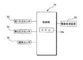
図3に示すように、制御部34は、本体32に設けられる。図4に示すように、CPU34a、ならびに図示しない揮発性およびまたは不揮発性のメモリを含み、後述するように各種センサの検出結果に基づいて各種信号を出力する。また、図2、図3および図4に示すように、本体32には、操作部材30の操作方向D2への動きを検出するための磁気センサ36が設けられる。磁気センサ36は、ホール素子などを含み、操作部材30に設けられる磁石38の磁力を検出する。磁石38は、操作部材30が初期位置から操作方向D2に回動することによって磁気センサ36と対向するように設けられる。 As shown in FIG. 3, the
操作部材30は、本体32に対して所定の操作方向に可動的に設けられる。本実施形態では、操作部材30は、本体32の中心軸(ハンドルバー100の軸)C回りに回動可能に本体32に設けられる。中心軸Cは、回転軸の一例である。操作部材30は、所定の初期位置から操作方向D2に押圧されることによって初期位置から所定角度(たとえば5度から30度の範囲)離反した操作位置に向けて回動するように構成される。操作部材30は、付勢部材60(図2参照)によって操作方向D2とは反対の方向に付勢されており、操作後に初期位置に戻る。つまり、操作部材30は、トリガーレバーとして構成される。付勢部材60は、たとえば、捩りコイルバネであり、一端が操作部材30に係合し、他端が本体32に係合する。磁気センサ36は、操作部材30の操作方向D2への回動に伴って磁石38の磁力を検出し、所定の信号を制御部34に入力する。これによって操作部材30の動作が検出される。すなわち、本実施形態では制御部34および磁気センサ36によって動作検出部が構成される。 The
操作部材30は、中心軸C回りに回動可能に本体32に設けられる基部42を有する。また、操作部材30は、基部42から別々に基部42の実質的に径方向に延びるように設けられる第1操作部44および第2操作部46を有する。第1操作部44は、中心軸Cから基部42の径方向に第1距離L1(図2参照)を有するように延びる。第2操作部46は、中心軸Cから基部42の径方向に第2距離L2を有するように延びる。第1距離L1と第2距離L2とは互いに異なる。本実施形態では、第2距離L2が第1距離L1よりも大きくなるように第1操作部44および第2操作部46が設けられる。また、第1操作部44と第2操作部46とは、基部42に対して中心軸C回りの異なる位置に配置される。本実施形態では、第2操作部46が第1操作部44よりも操作方向D2の下流側に配置される。第1操作部44および第2操作部46の一方は、電動変速装置80にたとえばシフトアップ動作をさせるために設けられる。第1操作部44および第2操作部46の他方は、電動変速装置80にたとえばシフトダウン動作をさせるために設けられる。 The
第1操作部44は、第1押圧部44aを先端部(基部42とは反対側の端部)に有する。第2操作部46は、第2押圧部46aを先端部に有する。図3に示すように、第1押圧部44aは、第1押圧面44bを有する。第2押圧部46aは、第2押圧面46bを有する。第1押圧面44bおよび第2押圧面46bは、たとえば、触感によって識別可能な異なる曲面形状を有する。本実施形態では、第1押圧面44bおよび第2押圧面46bは、たとえば異なる深さで僅かに凹んで形成される。また、第1押圧面44bは、第2押圧面46bよりも面積が小さい。 The
図3に示すように、第1押圧部44aには、第1操作部44の操作を検出するための第1圧力センサ50が設けられる。第2押圧部46bには、第2操作部46の操作を検出するための第2圧力センサ52が設けられる。第1圧力センサ50は、第1操作部44の第1押圧面44bに埋設され、第1押圧面44bへの押圧に伴って制御部34に所定の信号を入力する。第2圧力センサ52は、第2操作部46の第2押圧面46bに埋設され、第2押圧面46bへの押圧に伴って制御部34に所定の信号を入力する。本実施形態では、操作部材30の第1操作部44および第2操作部46のいずれが操作方向D2に操作されたかを検出するための操作検出部が、制御部34、第1圧力センサ50および第2圧力センサ52によって構成される。詳しくは、第1操作部44への操作を検出するための第1検出部が、制御部34および第1圧力センサ50によって構成される。また、第2操作部46への操作を検出するための第2検出部が、制御部34および第2圧力センサ52によって構成される。 As shown in FIG. 3, the
また、制御部34は、信号出力部としても機能する。このような機能は、所定のソフトウェアプログラムを実行することによって達成される。制御部34は、磁気センサ36、第1圧力センサ50、第2圧力センサ52からの入力に応じて、第1操作信号および第2操作信号を電動変速装置80に出力する。具体的には、第1圧力センサ50からの入力および磁気センサ36からの入力に応じて第1操作信号を電動変速装置80に出力する。また、第2圧力センサ52からの入力および磁気センサ36からの入力に応じて第2操作信号を電動変速装置80に出力する。第1操作信号および第2操作信号の一方は、電動変速装置80に供給され、たとえばシフトアップ信号として用いられる。また、第1操作信号および第2操作信号の他方は、電動変速装置80に供給され、たとえばシフトダウン信号として用いられる。 The
このように構成された操作装置10では、操作方向D2に可動的に設けられる一つの操作部材30に第1操作部44と第2操作部46とが設けられる。この第1操作部44および第2操作部46のいずれかを操作すると、第1圧力センサ50および第2圧力センサ52の一方を介して制御部34によって、いずれの操作部が操作方向D2に操作されたかが検出される。また、磁気センサ36を介して制御部34によって、操作部材30が操作位置まで回動したか否かが検出される。これらの検出結果に基づいて電動変速装置80などの電動装置を操作するための操作信号(第1操作信号および第2操作信号)が制御部34から電動変速装置80に向けて出力される。これによって、2つの操作部材を取り付け部材に対して別々に可動的を設けずとも複数の操作信号を出力可能になる。すなわち、電動装置を操作するための操作装置10を簡素にできる。 In the operating
また、第1操作ユニット12と第2操作ユニット14とを組み合わせることによって、第1操作ユニット12と第2操作ユニット14とをハンドルバー100に取り付けるための取り付け部材を別々に準備する必要がなく、ハンドルバー100上の構成を簡素にできる。さらに、第2操作ユニット14がハンドルバー100の中心軸C回りに回動可能な操作部材30を有することによって、レバーなどの回動軸を別軸にする場合に比べて装置をコンパクトに構成できる。この点からもハンドルバー100上の構成を簡素にできる。 Further, by combining the
<第2実施形態>
上記第1実施形態では、第1操作部44および第2操作部46に対応して第1押圧部44aおよび第2押圧部46aを設けたが、図5に示す第2実施形態の操作装置110のように構成してもよい。操作装置110では、操作部材130が一つの押圧部144aを有する。押圧部144aの押圧面144bには、第1圧力センサ150と第2圧力センサ152とが設けられる。第2実施形態では、第1圧力センサ150によって押圧を検出可能な領域が第1操作部144であり、第2圧力センサ152によって押圧を検出可能な領域が第2操作部146である。また、第1操作部144と第2操作部146とを識別可能にするために、第1操作部144および第2操作部146は、押圧面144bの他の領域よりも突出して形成される。その他の構成は、第1実施形態と同様であるため、説明を省略する。Second Embodiment
In the first embodiment, the first
<他の実施形態>
以上、本発明の一実施形態について説明したが、本発明は上記実施形態に限定されるものではなく、発明の要旨を逸脱しない範囲で種々の変更が可能である。特に、本明細書に書かれた複数の実施形態及び変形例は必要に応じて任意に組合せ可能である。<Other embodiments>
As mentioned above, although one Embodiment of this invention was described, this invention is not limited to the said embodiment, A various change is possible in the range which does not deviate from the summary of invention. In particular, a plurality of embodiments and modifications described in this specification can be arbitrarily combined as necessary.
(a)上記2つの実施形態では、自転車のハンドルバーに設けられる操作装置を例に本発明を説明したが、本発明はこれに限定されない。本発明は、自転車のフレームなどの自転車のハンドルバー以外の部材に取り付けられる操作装置にも適用できる。 (A) In the above-described two embodiments, the present invention has been described by taking the operation device provided on the handlebar of the bicycle as an example, but the present invention is not limited to this. The present invention can also be applied to an operating device attached to a member other than a bicycle handlebar such as a bicycle frame.
(b)上記2つの実施形態では、自転車の電動装置として電動変速装置を例示したが、本発明はこれに限定されない。本発明が適用される自転車の電動装置としては、電動サスペンション、電動シートポスト、および自転車を駆動する電動駆動装置も含まれる。 (B) In the above two embodiments, the electric transmission is exemplified as the bicycle electric device, but the present invention is not limited to this. The bicycle electric device to which the present invention is applied includes an electric suspension, an electric seat post, and an electric drive device for driving the bicycle.
(c)上記2つの実施形態では、自転車のブレーキ操作装置である第1操作ユニットと一体化される操作装置を例示したが、本発明はこれに限定されない。電動装置を操作可能な単独の装置として操作装置を構成してもよい (C) In the above two embodiments, the operation device integrated with the first operation unit, which is a bicycle brake operation device, is exemplified, but the present invention is not limited to this. The operating device may be configured as a single device capable of operating the electric device.
(d)上記2つの実施形態では、操作検出部と動作検出部との検出結果に基づいて操作信号を出力したが、本発明はこれに限定されない。操作検出部の検出結果のみに基づいて操作信号を出力するようにしてもよい。 (D) In the above two embodiments, the operation signal is output based on the detection results of the operation detection unit and the operation detection unit, but the present invention is not limited to this. The operation signal may be output based only on the detection result of the operation detection unit.
(e)上記2つの実施形態では、第1検出部が第1圧力センサを含み、第2検出部が第2圧力センサを含む場合について説明したが、本発明はこれに限定されない。たとえば、第1検出部が第1静電容量センサを含み、第2検出部が第2静電容量センサを含むようにしてもよい。また、第1検出部が第1押圧スイッチを含み、第2検出部が第2押圧スイッチを含むようにしてもよい。すなわち、操作検出部には任意のセンサ・スイッチを用いることができる。 (E) In the two embodiments described above, the first detection unit includes the first pressure sensor and the second detection unit includes the second pressure sensor. However, the present invention is not limited to this. For example, the first detection unit may include a first capacitance sensor, and the second detection unit may include a second capacitance sensor. The first detection unit may include a first press switch, and the second detection unit may include a second press switch. That is, any sensor switch can be used for the operation detection unit.
(f)上記2つの実施形態では、動作検出部が操作部材に設けられる磁石を検出する磁気センサを含む場合について説明したが、本発明はこれに限定されない。動作検出部には、操作部材の動作を検出できる任意のセンサ・スイッチを用いることができ、たとえばロータリーエンコーダ、ポテンショメータなどの回転検出器を用いることができる。 (F) In the above-described two embodiments, the case where the motion detection unit includes a magnetic sensor that detects a magnet provided on the operation member has been described, but the present invention is not limited to this. As the motion detection unit, any sensor switch that can detect the motion of the operation member can be used. For example, a rotation detector such as a rotary encoder or a potentiometer can be used.
(g)上記2つの実施形態では、第1操作部および第2操作部にそれぞれ圧力スイッチを含む操作検出部を設けたが、操作検出部は、第1操作部および第2操作部のいずれか一方だけに設けてもよい。この場合、動作検出部の検出結果と操作検出部の検出結果とによって操作信号を出力すればよい。具体的に、第1操作部に操作検出部を設ける場合、操作検出部が第1操作部の操作を検出し、かつ動作検出部が操作部材の動作を検出する場合、信号出力部が第1操作信号を出力する。また、動作検出部が操作部材の動作を検出し、かつ操作検出部が第1操作部の操作を検出しない場合、信号出力部が第2操作信号を出力する。 (G) In the above two embodiments, the operation detection unit including the pressure switch is provided in each of the first operation unit and the second operation unit. However, the operation detection unit is either the first operation unit or the second operation unit. You may provide only in one side. In this case, an operation signal may be output based on the detection result of the motion detection unit and the detection result of the operation detection unit. Specifically, when the operation detection unit is provided in the first operation unit, the operation detection unit detects the operation of the first operation unit, and the operation detection unit detects the operation of the operation member, the signal output unit is the first Outputs an operation signal. When the operation detection unit detects the operation of the operation member and the operation detection unit does not detect the operation of the first operation unit, the signal output unit outputs the second operation signal.
10,110 操作装置
18 取り付け部材
30,130 操作部材
34 制御部
36 磁気センサ
42 基部
44,144 第1操作部
46,146 第2操作部
50,150 第1圧力センサ
52,152 第2圧力センサ
60 付勢部材
D2 操作方向
C 中心軸(回転軸の一例)
L1 第1距離
L2 第2距離DESCRIPTION OF SYMBOLS 10,110
L1 1st distance L2 2nd distance
Claims (10)
Translated fromJapanese前記自転車に取り付け可能な取り付け部材と、
少なくとも第1操作部と第2操作部とを有し、前記取り付け部材に対し所定の操作方向に可動的に設けられる操作部材と、
前記操作部材の前記第1操作部および前記第2操作部のいずれが前記操作方向に操作されたかを検出するための操作検出部と、
前記電動装置を操作するための操作信号を前記操作検出部の検出結果に基づいて出力する信号出力部と、
を備える操作装置。An operating device for operating a bicycle electric device,
An attachment member attachable to the bicycle;
An operation member that has at least a first operation unit and a second operation unit, and is movably provided in a predetermined operation direction with respect to the attachment member;
An operation detection unit for detecting which of the first operation unit and the second operation unit of the operation member is operated in the operation direction;
A signal output unit that outputs an operation signal for operating the electric device based on a detection result of the operation detection unit;
An operating device comprising:
前記操作検出部は、前記第1操作部への操作を検出するための第1検出部と、前記第2操作部への操作を検出するための第2検出部と、を有する、請求項2に記載の操作装置。The first operation part and the second operation part are provided so as to extend in the radial direction of the base part separately from the base part,
The operation detection unit includes a first detection unit for detecting an operation on the first operation unit, and a second detection unit for detecting an operation on the second operation unit. The operating device according to 1.
前記信号出力部は、前記操作検出部の検出結果と前記動作検出部の検出結果とに基づいて前記操作信号を出力する、請求項3に記載の操作装置。An operation detection unit for detecting movement of the operation member in the operation direction;
The operation device according to claim 3, wherein the signal output unit outputs the operation signal based on a detection result of the operation detection unit and a detection result of the motion detection unit.
前記第2操作部は、前記回転軸から前記基部の径方向に第2距離を有するように延び、
第1距離と第2距離とは互いに異なる、請求項3または4に記載の操作装置。The first operating portion extends from the rotating shaft so as to have a first distance in a radial direction of the base portion,
The second operating portion extends from the rotating shaft so as to have a second distance in the radial direction of the base portion,
The operating device according to claim 3 or 4, wherein the first distance and the second distance are different from each other.
前記操作部材を前記初期位置に向けて前記操作方向とは反対方向に付勢する付勢部材をさらに備える、請求項2から9のいずれか1項に記載の操作装置。The operation member can swing from the initial position to the operation position in the operation direction as the base rotates.
The operating device according to claim 2, further comprising a biasing member that biases the operating member toward the initial position in a direction opposite to the operation direction.
Priority Applications (5)
| Application Number | Priority Date | Filing Date | Title |
|---|---|---|---|
| JP2013113832AJP2014231331A (en) | 2013-05-30 | 2013-05-30 | Manipulator |
| TW102125388ATWI548556B (en) | 2013-05-30 | 2013-07-16 | Operating device |
| CN201310454785.5ACN104210602B (en) | 2013-05-30 | 2013-09-30 | Operation device |
| US14/283,334US9428247B2 (en) | 2013-05-30 | 2014-05-21 | Control device |
| DE102014107603.6ADE102014107603A1 (en) | 2013-05-30 | 2014-05-28 | CONTROL DEVICE |
Applications Claiming Priority (1)
| Application Number | Priority Date | Filing Date | Title |
|---|---|---|---|
| JP2013113832AJP2014231331A (en) | 2013-05-30 | 2013-05-30 | Manipulator |
Publications (1)
| Publication Number | Publication Date |
|---|---|
| JP2014231331Atrue JP2014231331A (en) | 2014-12-11 |
Family
ID=51899589
Family Applications (1)
| Application Number | Title | Priority Date | Filing Date |
|---|---|---|---|
| JP2013113832APendingJP2014231331A (en) | 2013-05-30 | 2013-05-30 | Manipulator |
Country Status (5)
| Country | Link |
|---|---|
| US (1) | US9428247B2 (en) |
| JP (1) | JP2014231331A (en) |
| CN (1) | CN104210602B (en) |
| DE (1) | DE102014107603A1 (en) |
| TW (1) | TWI548556B (en) |
Families Citing this family (9)
| Publication number | Priority date | Publication date | Assignee | Title |
|---|---|---|---|---|
| EP3192731B1 (en)* | 2012-08-21 | 2019-11-20 | Gustav Magenwirth GmbH & Co. KG | Electronically controlled suspension system, method and computer program |
| JP2014196060A (en)* | 2013-03-29 | 2014-10-16 | 株式会社シマノ | Operation device |
| US9656717B2 (en)* | 2015-02-06 | 2017-05-23 | Shimano Inc. | Bicycle operating device |
| IT201600081324A1 (en) | 2016-08-02 | 2018-02-02 | Campagnolo Srl | Bicycle control device |
| US10183721B2 (en)* | 2016-08-10 | 2019-01-22 | Shimano Components (Malaysia) Sdn. Bhd. | Bicycle control device |
| US11827307B2 (en)* | 2021-05-05 | 2023-11-28 | Shimano Inc. | Operating device for human-powered vehicle |
| US11981391B2 (en)* | 2021-05-05 | 2024-05-14 | Shimano Inc. | Operating device for human-powered vehicle |
| US12060131B2 (en)* | 2021-09-13 | 2024-08-13 | Shimano Inc. | Operating device for human-powered vehicle |
| CN114305993B (en)* | 2021-12-20 | 2023-11-14 | 国家康复辅具研究中心 | Handle device and intelligent walking aid device |
Family Cites Families (6)
| Publication number | Priority date | Publication date | Assignee | Title |
|---|---|---|---|---|
| JP3321045B2 (en)* | 1996-12-20 | 2002-09-03 | 株式会社シマノ | Bicycle electrical operating device |
| JP3566682B2 (en)* | 2001-09-21 | 2004-09-15 | 株式会社シマノ | Bicycle shift control device and manual shift control device used therefor |
| JP2008168751A (en) | 2007-01-11 | 2008-07-24 | Shimano Inc | Brake and gear shift operating device for bicycle |
| US7806022B2 (en)* | 2007-05-16 | 2010-10-05 | Shimano Inc. | Bicycle component actuating device |
| US20090054182A1 (en)* | 2007-08-21 | 2009-02-26 | Shimano Inc. | Bicycle component with position sensing |
| JP5064342B2 (en)* | 2008-09-19 | 2012-10-31 | 本田技研工業株式会社 | Throttle opening detection device for saddle-ride type vehicles |
- 2013
- 2013-05-30JPJP2013113832Apatent/JP2014231331A/enactivePending
- 2013-07-16TWTW102125388Apatent/TWI548556B/enactive
- 2013-09-30CNCN201310454785.5Apatent/CN104210602B/enactiveActive
- 2014
- 2014-05-21USUS14/283,334patent/US9428247B2/ennot_activeExpired - Fee Related
- 2014-05-28DEDE102014107603.6Apatent/DE102014107603A1/enactivePending
Also Published As
| Publication number | Publication date |
|---|---|
| TW201444729A (en) | 2014-12-01 |
| TWI548556B (en) | 2016-09-11 |
| US9428247B2 (en) | 2016-08-30 |
| DE102014107603A1 (en) | 2014-12-04 |
| US20140354038A1 (en) | 2014-12-04 |
| CN104210602A (en) | 2014-12-17 |
| CN104210602B (en) | 2017-03-15 |
Similar Documents
| Publication | Publication Date | Title |
|---|---|---|
| JP2014231331A (en) | Manipulator | |
| JP5311556B2 (en) | Throttle grip device | |
| JP5811402B2 (en) | Steering device | |
| JP5309294B2 (en) | Joystick | |
| CN107923459B (en) | Disc brake, in particular for commercial vehicles | |
| JP6183351B2 (en) | Selectable one-way clutch shaft support structure | |
| CN110103930A (en) | Sensor unit | |
| TWI549853B (en) | Operating device | |
| JP2010521027A5 (en) | ||
| JP2014118139A (en) | Stroke sensor unit for brake pedal device | |
| JP2010280304A (en) | Throttle grip device | |
| JP5442323B2 (en) | Throttle grip device | |
| EP2998616B1 (en) | Gear-shift-operation transmission device and transmission for saddle-ride type vehicle | |
| JP2008241564A (en) | Rudder angle detection device and steering device | |
| JP2010168025A (en) | Throttle grip device | |
| JP2006279549A5 (en) | ||
| JP2010160104A (en) | Shift position detector | |
| KR100654335B1 (en) | Pedal Stroke Sensor Mounting Structure | |
| CN105204524B (en) | Control distant bar | |
| JP2019064312A (en) | Shift lever position detecting device | |
| JP2005055392A (en) | Rotation angle and torque detection device | |
| JP2014031035A (en) | Engine-assisted saddle-riding type vehicle | |
| JP2019084922A (en) | Shift device | |
| JP2018161984A (en) | Vehicular operation pedal device | |
| JP2018043557A (en) | Shifting device |