JP2014230392A - Bidirectional power source device - Google Patents
Bidirectional power source deviceDownload PDFInfo
- Publication number
- JP2014230392A JP2014230392AJP2013108060AJP2013108060AJP2014230392AJP 2014230392 AJP2014230392 AJP 2014230392AJP 2013108060 AJP2013108060 AJP 2013108060AJP 2013108060 AJP2013108060 AJP 2013108060AJP 2014230392 AJP2014230392 AJP 2014230392A
- Authority
- JP
- Japan
- Prior art keywords
- bidirectional
- secondary battery
- bridge converter
- power supply
- coil
- Prior art date
- Legal status (The legal status is an assumption and is not a legal conclusion. Google has not performed a legal analysis and makes no representation as to the accuracy of the status listed.)
- Pending
Links
- 230000002457bidirectional effectEffects0.000titleclaimsabstractdescription112
- 238000004804windingMethods0.000claimsdescription17
- 238000007599dischargingMethods0.000description6
- 230000007423decreaseEffects0.000description5
- 239000004020conductorSubstances0.000description1
- 239000000446fuelSubstances0.000description1
- 238000012423maintenanceMethods0.000description1
- 230000001360synchronised effectEffects0.000description1
Images


Landscapes
- Dc-Dc Converters (AREA)
Abstract
Description
Translated fromJapanese商用電源から二次電池に、更に必要な場合は二次電池から商用電源に電力を供給する双方向電源装置に関する。The present invention relates to a bidirectional power supply apparatus that supplies electric power from a commercial power source to a secondary battery, and further, when necessary, from the secondary battery to the commercial power source.
商用電源から二次電池に電力を供給(充電)し、緊急時に二次電池から商用電源に電力を供給(放電)する双方向電源装置については、例えば、特許文献1等で知られている。
図5に従来例に係る双方向フルブリッジコンバータを用いた双方向電源装置100を示すが、1)商用電源101に接続される第1の双方向AC/DCコンバータ102と、2)それぞれにダイオード104〜107が並列に接続されたスイッチング素子108〜111を備えた第2の双方向AC/DCコンバータ112と、3)高周波トランス114と、4)それぞれにダイオード115〜118が並列に接続されたスイッチング素子119〜122を備えた第3の双方向AC/DCコンバータ123とを直列に接続し、商用電源101から二次電池125に電力を供給又は二次電池125から商用電源101に電力を供給していた。A bidirectional power supply device that supplies (charges) power from a commercial power supply to a secondary battery and supplies (discharges) power from the secondary battery to the commercial power supply in an emergency is known from, for example, Patent Document 1.
FIG. 5 shows a bidirectional
この場合、二次電池125を充電する場合には、商用電源101からの電力を第1の双方向AC/DCコンバータ102で直流に変換し、第2の双方向AC/DCコンバータ112で20〜100kHzの高周波交流に変換し、高周波トランス114を介して第3の双方向AC/DCコンバータ123に供給して直流として二次電池125を充電していた。また、二次電池125を放電する場合は、第3の双方向AC/DCコンバータ123で高周波交流にし、高周波トランス114を介して第2の双方向AC/DCコンバータ112に供給し直流にした後、第1の双方向AC/DCコンバータ102に供給して商用交流に変換して商用電源101に供給していた。In this case, when the
しかしながら、高周波トランス114の巻数比は二次電池125の充電電圧を基準にして設定される。即ち、二次電池125の充電電圧は、第1の双方向AC/DCコンバータ102の出力電圧V(商用電源101の電圧と同一かやや高い)と第2の双方向AC/DCコンバータ112で行うPWM制御のデューティ比r1と、高周波トランス114の巻数比n1によって決定される。ここで、デューティ比R1を小さく取ると高周波トランス114の二次側電圧は小さくなるので、巻数比n1を大きくする必要がある(即ち、m2/m1>1、m1、m2は一次側コイル及び二次側コイルの巻数)。巻数比n1を大きくすると、二次電池125の放電を行う場合は、高周波トランス114によって出力電圧が下がり、商用電源101に供給できないので、通常はm1=m2としている。なお、入力電圧と出力電圧の関係は以下の通りとなる。
出力電圧=(m2/m1)×ton/(ton+toff)×入力電圧、ここで、tonはPWM制御の通電時間、toffはPWM制御の非通電時間を示す。However, the turn ratio of the high-
Output voltage = (m2 / m1) × ton / (ton + toff) × input voltage, where ton represents the energization time of PWM control, and toff represents the non-energization time of PWM control.
ところが、高周波トランス114の巻数比n1=1としても、放電時に二次電池125の電圧が下がると、高周波トランス114の出力電圧(一次側電圧)が下がる。そこで、PWM制御を行って直流を交流にする第3の双方向AC/DCコンバータ123のデューティ比を挙上げることになるが、100%以上は不可能である。そこで、図6に示すように二次電池125側に昇圧降圧回路(チョッパー)127を設け、二次電池125の電圧が下がった場合には、昇圧降圧回路127によって二次電池125の電圧降下を補償している。However, even when the turn ratio n1 = 1 of the high-
このような昇圧降圧回路127を設けると、全体の装置が複雑化して価格も高騰し、更に、余分なメンテナンスが必要となる。
本発明はかかる事情に鑑みてなされたもので、比較的簡単に構成でき、廉価な双方向電源装置を提供することを目的とする。Providing such a step-up / step-down
The present invention has been made in view of such circumstances, and an object thereof is to provide an inexpensive bidirectional power supply apparatus that can be configured relatively easily.
前記目的に沿う第1の発明に係る双方向電源装置は、巻数m1の一次側コイル及び巻数m2の二次側コイルを備えた高周波トランスと、該高周波トランスの二次側に接続される双方向フルブリッジコンバータとを有し、該双方向フルブリッジコンバータに二次電池を接続して該二次電池の充放電を行う双方向電源装置において、
前記双方向フルブリッジコンバータが整流回路として働く前記二次電池の充電時には、前記双方向フルブリッジコンバータを前記巻数m2の二次側コイルに接続して全波整流を行い、前記双方向フルブリッジコンバータがインバータとして働く前記二次電池の放電時には、前記双方向フルブリッジコンバータを前記巻数m2より少ない巻数m3の二次側コイルに接続する。なお、m1、m2、m3は理解を容易にするために付したもので、実施の形態に説明する具体的数字によって限定されるものではない(以下の説明においても同じ)。The bidirectional power supply according to the first invention that meets the above-described object is a high-frequency transformer that includes a primary coil having a winding number m1 and a secondary coil having a winding number m2, and a bidirectional device that is connected to the secondary side of the high-frequency transformer. In a bidirectional power supply device that has a full bridge converter and connects and charges a secondary battery to the bidirectional full bridge converter to charge and discharge the secondary battery,
When charging the secondary battery in which the bidirectional full bridge converter functions as a rectifier circuit, the bidirectional full bridge converter is connected to the secondary coil having the number of turns m2 to perform full wave rectification, and the bidirectional full bridge converter. When the secondary battery serving as an inverter is discharged, the bidirectional full bridge converter is connected to a secondary coil having a winding number m3 smaller than the winding number m2. Note that m1, m2, and m3 are given for ease of understanding and are not limited by the specific numbers described in the embodiments (the same applies to the following description).
第2の発明に係る双方向電源装置は、第1の発明に係る双方向電源装置において、前記双方向フルブリッジコンバータは、前記二次電池の充電時に前記巻数m2の二次側コイルの電圧を全波整流する補助ダイオードを備えている。A bidirectional power supply according to a second invention is the bidirectional power supply according to the first invention, wherein the bidirectional full-bridge converter generates a voltage of the secondary coil having the number of turns m2 when the secondary battery is charged. An auxiliary diode for full-wave rectification is provided.
第3の発明に係る双方向電源装置は、第1、第2の発明に係る双方向電源装置において、前記巻数m3の二次側コイルは、前記巻数m2の二次側コイルに中間タップを設けて形成される。A bidirectional power supply according to a third invention is the bidirectional power supply according to the first and second inventions, wherein the secondary coil having the number of turns m3 is provided with an intermediate tap on the secondary coil having the number of turns m2. Formed.
そして、第4の発明に係る双方向電源装置は、第1〜第3の発明に係る双方向電源装置において、前記巻数m2の二次側コイルにはスイッチが設けられて、前記二次電池の放電時に、前記双方向フルブリッジコンバータが前記インバータとして働き、前記巻数m3の二次側コイルに電力が供給されている場合は、前記スイッチをオフにする。The bidirectional power supply according to a fourth aspect of the present invention is the bidirectional power supply according to the first to third aspects of the present invention, wherein a switch is provided in the secondary coil having the number of turns m2, and the secondary battery At the time of discharging, the bidirectional full bridge converter functions as the inverter, and when power is supplied to the secondary coil having the number of turns m3, the switch is turned off.
第1〜第4の発明に係る双方向電源装置は、二次電池の電圧が下がった場合であっても、昇圧回路(及び降圧回路)を必要とせず、二次電池から高周波トランス側に向けて電力供給が可能となるので、より部品点数が少なく、廉価に双方向電源装置を構成できる。The bidirectional power supply according to the first to fourth aspects of the present invention does not require a booster circuit (and a step-down circuit) even when the voltage of the secondary battery drops, and is directed from the secondary battery to the high-frequency transformer side. Therefore, the bidirectional power supply apparatus can be constructed at a low cost with fewer parts.
特に、第2の発明に係る双方向電源装置は、双方向フルブリッジコンバータが、二次電池の充電時に巻数m2の二次側コイルの電圧を全波整流する補助ダイオードを備えているので、二次電池を確実に充電できる高い直流電圧を得ることができる。In particular, in the bidirectional power supply device according to the second aspect of the invention, the bidirectional full bridge converter includes an auxiliary diode that full-wave rectifies the voltage of the secondary coil having the number of turns m2 when the secondary battery is charged. A high DC voltage capable of reliably charging the secondary battery can be obtained.
第3の発明に係る双方向電源装置は、巻数m3の二次側コイルが、巻数m2の二次側コイルに中間タップを設けて形成されるので、二次電池の充電時の高周波トランスの利用効率が向上する。In the bidirectional power supply device according to the third aspect of the invention, since the secondary coil having the number of turns m3 is formed by providing an intermediate tap on the secondary side coil having the number of turns m2, the high-frequency transformer is used when charging the secondary battery. Efficiency is improved.
第4の発明に係る双方向電源装置は、巻数m2の二次側コイルにスイッチが設けられて、双方向フルブリッジコンバータが巻数m3の二次側コイルに接続されている場合はスイッチをオフにしているので、回路の循環電流を減少できる。In the bidirectional power supply according to the fourth aspect of the present invention, when a switch is provided in the secondary coil having the number of turns m2, and the bidirectional full bridge converter is connected to the secondary coil having the number of turns m3, the switch is turned off. Therefore, the circulating current of the circuit can be reduced.
続いて、添付した図面を参照しながら、本発明を具体化した実施の形態について説明する。
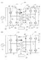
図1(A)、(B)、図2(A)、(B)に示すように、本発明の一実施の形態に係る双方向電源装置10は、商用電源11を第1の双方向フルブリッジコンバータ12によって直流にし、この直流を第2の双方向フルブリッジコンバータ13によって高周波交流とし、この高周波電力を高周波トランス14を介して、高周波トランス14の二次側に接続される第3の双方向フルブリッジコンバータ(本発明に係る双方向フルブリッジコンバータになる)15に供給し、直流に変換して第3の双方向フルブリッジコンバータ15に接続される二次電池16を充電する二次電池充放電電源装置18に使用されている。Next, embodiments of the present invention will be described with reference to the accompanying drawings.
As shown in FIGS. 1A, 1B, 2A, and 2B, a
この実施の形態においては、双方向フルブリッジコンバータ15には、それぞれ2組が直列かつ並列に接続されたスイッチング素子20〜23と、スイッチング素子20〜23に極性を逆にして並列に接続されたダイオード24〜27を有している。この双方向フルブリッジコンバータ15には、更に並列(正確には逆並列)にダイオード(補助ダイオードの一例)28、29が接続されている。高周波トランス14の二次側コイル31は中間タップ32を有し、この中間タップ32は双方向フルブリッジコンバータ15の一方の入出力部33に接続されて、他方の入出力部34には二次側コイル31の一側巻き端部35が接続されている。また、二次側コイル31の他側巻き端部35aにはスイッチ36aが設けられ、ダイオード28、29の連結部37aに接続されている。In this embodiment, two sets of bidirectional
一方、第2の双方向フルブリッジコンバータ13は、それぞれ2組が直列に接続されたスイッチング素子36〜39と、スイッチング素子36〜39に逆並列に接続されたダイオード40〜43とを有し、中間部の入出力端子44、45が高周波トランス14の一次側コイル46に接続されている。On the other hand, the second bidirectional full-
また、第1の双方向フルブリッジコンバータ12は商用電源(50Hz又は60Hz)11を直流に、又は直流から商用周波数に変換する回路を有している。第1、第2、第3の双方向フルブリッジコンバータ12、13、15は内部にインバータ制御及び単なる整流制御を行うプログラムを複数有する制御装置47によって制御されている。
なお、図1(B)、図2(A)、(B)に記載されているスイッチング素子、ダイオードは図1(A)に記載されているスイッチング素子、ダイオードと同一であるので、これらの符号を省略する。The first bidirectional
Note that the switching elements and diodes described in FIGS. 1B, 2A, and 2B are the same as the switching elements and diodes described in FIG. Is omitted.
図1(A)、(B)を参照しながら、二次電池充放電電源装置18によって二次電池16の充電を行う場合について説明する。
高周波トランス14の二次側コイル31に接続されるスイッチ36aはオンにしておき、制御装置47の指令によって、第1の双方向フルブリッジコンバータ12を整流回路とし、第2の双方向フルブリッジコンバータ13をインバータとし、第3の双方向フルブリッジコンバータ15を整流回路として作動させるようにする。A case where the
The
従って、商用電源11を第1の双方向フルブリッジコンバータ12によって直流に変換し、この直流を第2の双方向フルブリッジコンバータ13によって周波数が20〜100kHzの高周波交流に変換して、高周波トランス14の一次側コイル46に供給している。この場合の一次側コイル46の巻数m1と二次側コイル31の巻数m2は例えば同一巻数となって、高周波トランス14の一次側の電圧と二次側の電圧は同一となる。Therefore, the
二次側コイル31には巻数m3の位置に中間タップ32が設けられ、この実施の形態では、m3=m1/2=m2/2となっている。
なお、高周波トランス14を用いることによって、商用電源側の回路と二次電池側の回路が直流的に絶縁されると共に、第1、第2の双方向フルブリッジコンバータ12、13がインバータとして働く場合の波形から高調波が減少し、より装置の安定性がよくなる。The
When the
二次側コイル31の巻数m2側のスイッチ36aがオンとなっているので、第3の双方向フルブリッジコンバータ15は二次側コイル31に接続され、ダイオード28、29とダイオード26、27によるフルブリッジ整流器として作動し、二次電池16の両端に高電圧、即ち、二次側コイル31を全波整流した直流電圧がかかることになる。これによって、二次電池16の充電が行われる。なお、この装置は二次電池充放電電源装置18であるので、電流及び電圧を測定する計測器は設けられているが、説明は省略する。Since the
二次電池16の充電電圧及び電流の調整はインバータとして働く第2の双方向フルブリッジコンバータ13のPWM制御のデューティ比を変えて行う。なお、図1(A)、(B)の矢印a、bは第3の双方向フルブリッジコンバータ15の充電時の通電経路を示す。この場合、中間タップ32は一側巻き端部35と他側巻き端子35aの中間電位となるので、接続される導線には電流は流れない。The charging voltage and current of the
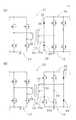
次に、図2(A)、(B)を参照して、この二次電池充放電電源装置18が二次電池16を放電させる場合、即ち、商用電源11に対して二次電池16から電力を供給する場合について説明する。二次電池16から電力を供給させる場合はスイッチ36aはオフにする。これによって、高周波トランス14の二次側コイル31の巻数m3に対する一次側コイル46の巻数m1は2倍となる。Next, referring to FIGS. 2A and 2B, when the secondary battery charging / discharging
第3の双方向フルブリッジコンバータ15はインバータとして働き、高周波電圧を高周波トランス14の巻数m3の二次側コイル31に供給する。一次側には二次側コイル31にかかる電圧の2倍の電圧が誘起され、整流回路として作動する第2の双方向フルブリッジコンバータ13によって直流に変換され、この直流はインバータとして働く第1の双方向フルブリッジコンバータ12に入力されて、商用電源11の周波数に変換され、位相も商用電源11に同期させて、商用電源11に供給される。The third bidirectional full-
ここで、第1の双方向フルブリッジコンバータ12の出力電圧は、PWM変調を行う第3の双方向フルブリッジコンバータ15のデューティ比によって決定される。従って、高周波トランス14の一次側、二次側コイル46、31の巻数m1、m3を考慮すると、一次側コイル46に発生する電圧V1は、二次電池16の電圧をVbとすると以下の式のようになる。
V1=Vb×(m1/m3)×ton/(ton+toff)
この高周波電圧V1を第2の双方向フルブリッジコンバータ13で整流し、第1の双方向フルブリッジコンバータ12で商用電源に変換すると、その電圧Vc=kV1となる(kは比例定数)。Here, the output voltage of the first bidirectional
V1 = Vb × (m1 / m3) × ton / (ton + toff)
When this high-frequency voltage V1 is rectified by the second bidirectional full-
従って、供給される商用電源11の電圧をVsとすると、Vc>Vsとなる。この場合、商用電源11に供給される電流Icは、Ic=(Vc−Vs)/R(Rは内部抵抗)となる。ここで、高周波トランス14の巻数比は一定値2であるので、第3の双方向フルブリッジコンバータ15のデューティ比を変えて、Icの値を決めることになる。Therefore, when the voltage of the supplied
二次電池16の端子電圧は、最初は規定値を維持しているが、放電させることによって電圧が下がり、例えば、電圧が半分になると従来の二次電池充放電電源装置では、商用電源側に電力を返すことは不可能になるが、本発明の場合、高周波トランス14の巻数比m1/m3を大きくしている(=2)ので、二次電池16の電圧が下がっても放電が可能となる。
なお、二次電池16を充電する場合は、巻数比を元に戻しているので、直流電圧を高圧(二次電池16の電圧より高い)とすることが可能となり二次電池16の充電が十分に可能となる。The terminal voltage of the
Note that when the
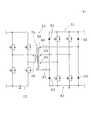
図3(A)、(B)、図4は本発明の他の実施の形態に係る双方向電源装置49〜51を用いた二次電池充放電電源装置52〜54を示す。なお、二次電池充放電電源装置52〜54は図1、図2に示す二次電池充放電電源装置18と実質同一であるので、異なる構成要素についてのみ説明する。3 (A), 3 (B), and 4 show secondary battery charge / discharge power supply devices 52-54 using bidirectional power supply devices 49-51 according to other embodiments of the present invention. Since secondary battery charge / discharge
図3(A)に示す二次電池充放電電源装置52においては、図1(A)に示すように、高周波トランス14の二次側コイル31の片側に接続されていたスイッチ36aを無くし、ダイオード29の片側にスイッチ55を設けて、第3の双方向フルブリッジコンバータ15がインバータとして作動する場合は、二次側コイル31の全体、即ち巻数m2の全部に流れるのを防止している。なお、第3の双方向フルブリッジコンバータ15を整流回路として作動させる場合は、スイッチ55をオンにする。In the secondary battery charge / discharge
また、図3(B)に示す二次電池充放電電源装置53においては、図1、図2に示すスイッチ36aを省略し、一側巻き端子35にスイッチ56として設けている。そして、二次側コイル31の他側巻き端子35aは、第3の双方向フルブリッジコンバータ15の連結部37aに接続されている。動作は、図1(A)、(B)、図2(A)、(B)に示す二次電池充放電電源装置18と同一である。Further, in the secondary battery charge / discharge
図4には、更に本発明の他の実施の形態に係る双方向電源装置51を示すが、二次側コイル58に2つの中間タップ59、60を設け、第3の双方向フルブリッジコンバータ61がダイオード62〜65を用いる整流回路として働く場合には、スイッチ66、67をオンにして二次側コイル58の両端(巻数m4)に接続する。勿論、二次側コイル58の両側に設けられているスイッチ66、67をオフにして、中間タップ59、60(巻数m5)からの出力を整流回路の入力としてもよい。FIG. 4 further shows a bidirectional
第3の双方向フルブリッジコンバータ61が二次電池16を電源とするインバータとして作動する場合には、スイッチ66、67をオフにして、中間タップ59、60の位置に高周波電圧を加えると、高周波トランス70の一次側コイル46に、巻数比(m1/m5)で昇圧された電圧が発生する。勿論、発生電圧が高い場合は、第3の双方向フルブリッジコンバータ61のデューティ比を調整する。
なお、高周波トランスの一次側コイルと、二次側コイルの巻数比は、二次電池の充電電圧を二次電池の最小放電電圧の比に合わせておくのが好ましい。When the third bidirectional full-
In addition, as for the turns ratio of the primary side coil and the secondary side coil of the high frequency transformer, it is preferable to match the charging voltage of the secondary battery with the ratio of the minimum discharge voltage of the secondary battery.
本発明は前記した実施の形態に限定されるものではなく、本発明の要旨を変更しない範囲でその構成を変更することもできる。例えば、本発明の双方向電源装置を、自動車用の電源回路、太陽電池を用いる電源、燃料電池を用いる電源等に適用することもできる。The present invention is not limited to the above-described embodiment, and the configuration thereof can be changed without changing the gist of the present invention. For example, the bidirectional power supply device of the present invention can also be applied to a power supply circuit for automobiles, a power supply using solar cells, a power supply using fuel cells, and the like.
10:双方向電源装置、11:商用電源、12:第1の双方向フルブリッジコンバータ、13:第2の双方向フルブリッジコンバータ、14:高周波トランス、15:第3の双方向フルブリッジコンバータ、16:二次電池、18:二次電池充放電電源装置、20〜23:スイッチング素子、24〜29:ダイオード、31:二次側コイル、32:中間タップ、33、34:入出力部、35:一側巻き端部、35a:他側巻き端子、36〜39:スイッチング素子、36a:スイッチ、37a:連結部、40〜43:ダイオード、44、45:入出力端子、46:一次側コイル、47:制御装置、49〜51:双方向電源装置、52〜54:二次電池充放電電源装置、55、56:スイッチ、58:二次側コイル、59、60:中間タップ、61:第3の双方向フルブリッジコンバータ、62〜65:ダイオード、66、67:スイッチ、70:高周波トランス10: bidirectional power supply device, 11: commercial power supply, 12: first bidirectional full bridge converter, 13: second bidirectional full bridge converter, 14: high frequency transformer, 15: third bidirectional full bridge converter, 16: secondary battery, 18: secondary battery charge / discharge power supply device, 20-23: switching element, 24-29: diode, 31: secondary coil, 32: intermediate tap, 33, 34: input / output unit, 35 : One side winding end, 35a: other side winding terminal, 36 to 39: switching element, 36a: switch, 37a: connecting portion, 40 to 43: diode, 44, 45: input / output terminal, 46: primary side coil, 47: control device, 49-51: bidirectional power supply device, 52-54: secondary battery charge / discharge power supply device, 55, 56: switch, 58: secondary coil, 59, 60: intermediate tap, 1: third bidirectional full bridge converter, 62 to 65: diode, 66 and 67: switch, 70: high-frequency transformer
Claims (4)
Translated fromJapanese前記双方向フルブリッジコンバータが整流回路として働く前記二次電池の充電時には、前記双方向フルブリッジコンバータを前記巻数m2の二次側コイルに接続して全波整流を行い、前記双方向フルブリッジコンバータがインバータとして働く前記二次電池の放電時には、前記双方向フルブリッジコンバータを前記巻数m2より少ない巻数m3の二次側コイルに接続することを特徴とする双方向電源装置。A high-frequency transformer having a primary coil having a winding number of m1 and a secondary-side coil having a winding number of m2, and a bidirectional full-bridge converter connected to a secondary side of the high-frequency transformer; In a bidirectional power supply device for connecting and charging a secondary battery to charge and discharge the secondary battery,
When charging the secondary battery in which the bidirectional full bridge converter functions as a rectifier circuit, the bidirectional full bridge converter is connected to the secondary coil having the number of turns m2 to perform full wave rectification, and the bidirectional full bridge converter. The bidirectional full-bridge converter is connected to a secondary coil having a number of turns m3 smaller than the number of turns m2 when the secondary battery serving as an inverter is discharged.
Priority Applications (1)
| Application Number | Priority Date | Filing Date | Title |
|---|---|---|---|
| JP2013108060AJP2014230392A (en) | 2013-05-22 | 2013-05-22 | Bidirectional power source device |
Applications Claiming Priority (1)
| Application Number | Priority Date | Filing Date | Title |
|---|---|---|---|
| JP2013108060AJP2014230392A (en) | 2013-05-22 | 2013-05-22 | Bidirectional power source device |
Publications (1)
| Publication Number | Publication Date |
|---|---|
| JP2014230392Atrue JP2014230392A (en) | 2014-12-08 |
Family
ID=52129767
Family Applications (1)
| Application Number | Title | Priority Date | Filing Date |
|---|---|---|---|
| JP2013108060APendingJP2014230392A (en) | 2013-05-22 | 2013-05-22 | Bidirectional power source device |
Country Status (1)
| Country | Link |
|---|---|
| JP (1) | JP2014230392A (en) |
- 2013
- 2013-05-22JPJP2013108060Apatent/JP2014230392A/enactivePending
Similar Documents
| Publication | Publication Date | Title |
|---|---|---|
| CN105637750B (en) | Power-converting device | |
| JP5762617B2 (en) | DC / DC converter | |
| TWI536709B (en) | Power systme and method for providing power | |
| CN105659484B (en) | power conversion device | |
| JP5594322B2 (en) | Switching power supply | |
| JP5903628B2 (en) | Power converter | |
| JPWO2016063678A1 (en) | Power converter | |
| JP2014087134A (en) | Dc/dc converter | |
| US20170117731A1 (en) | Power source device | |
| JP5547603B2 (en) | Power supply | |
| CN103731036A (en) | Bidirectional DC/DC Converter | |
| JP6025885B2 (en) | Power converter | |
| KR101601549B1 (en) | Method for battery charging control and apparatus therefor | |
| JP2014171313A (en) | Dc/dc converter | |
| JP2013116003A (en) | Lighting device | |
| JP3874291B2 (en) | Power supply | |
| JP2016146681A (en) | Power conversion device | |
| KR101100000B1 (en) | Power converter | |
| JP2014230392A (en) | Bidirectional power source device | |
| JP2022138710A (en) | DC-DC converter and vehicle | |
| JP2016135062A (en) | Electric power conversion system | |
| JP2014192963A (en) | Uninterruptible power supply | |
| WO2018235455A1 (en) | Three phase AC isolated switching power supply | |
| JP7129927B2 (en) | Isolated switching power supply | |
| JP2011172346A (en) | Direct current power supply device, and voltage generation method |