JP2014230179A - Imaging apparatus and imaging method - Google Patents
Imaging apparatus and imaging methodDownload PDFInfo
- Publication number
- JP2014230179A JP2014230179AJP2013109476AJP2013109476AJP2014230179AJP 2014230179 AJP2014230179 AJP 2014230179AJP 2013109476 AJP2013109476 AJP 2013109476AJP 2013109476 AJP2013109476 AJP 2013109476AJP 2014230179 AJP2014230179 AJP 2014230179A
- Authority
- JP
- Japan
- Prior art keywords
- image
- image signal
- signal
- light
- correlation
- Prior art date
- Legal status (The legal status is an assumption and is not a legal conclusion. Google has not performed a legal analysis and makes no representation as to the accuracy of the status listed.)
- Pending
Links
- 238000003384imaging methodMethods0.000titleclaimsabstractdescription58
- 230000007274generation of a signal involved in cell-cell signalingEffects0.000claimsabstractdescription24
- 238000001514detection methodMethods0.000claimsabstractdescription18
- 238000000034methodMethods0.000claimsdescription14
- 230000035945sensitivityEffects0.000abstractdescription30
- 238000006243chemical reactionMethods0.000abstractdescription3
- 230000003595spectral effectEffects0.000description14
- 230000003287optical effectEffects0.000description8
- 238000004364calculation methodMethods0.000description4
- 238000010586diagramMethods0.000description4
- 238000005286illuminationMethods0.000description3
- 238000012986modificationMethods0.000description3
- 230000004048modificationEffects0.000description3
- 238000005401electroluminescenceMethods0.000description2
- 230000002238attenuated effectEffects0.000description1
- 230000000903blocking effectEffects0.000description1
- 239000003086colorantSubstances0.000description1
- 230000000295complement effectEffects0.000description1
- 150000001875compoundsChemical class0.000description1
- 238000005314correlation functionMethods0.000description1
- 230000003247decreasing effectEffects0.000description1
- 238000000295emission spectrumMethods0.000description1
- 239000004973liquid crystal related substanceSubstances0.000description1
- 239000011159matrix materialSubstances0.000description1
- 229910044991metal oxideInorganic materials0.000description1
- 150000004706metal oxidesChemical class0.000description1
- 238000010606normalizationMethods0.000description1
- 239000004065semiconductorSubstances0.000description1
Images


Classifications
- H—ELECTRICITY
- H04—ELECTRIC COMMUNICATION TECHNIQUE
- H04N—PICTORIAL COMMUNICATION, e.g. TELEVISION
- H04N13/00—Stereoscopic video systems; Multi-view video systems; Details thereof
- H04N13/20—Image signal generators
- H04N13/257—Colour aspects
- H—ELECTRICITY
- H04—ELECTRIC COMMUNICATION TECHNIQUE
- H04N—PICTORIAL COMMUNICATION, e.g. TELEVISION
- H04N13/00—Stereoscopic video systems; Multi-view video systems; Details thereof
- H04N13/20—Image signal generators
- H04N13/204—Image signal generators using stereoscopic image cameras
- H04N13/239—Image signal generators using stereoscopic image cameras using two 2D image sensors having a relative position equal to or related to the interocular distance
- H—ELECTRICITY
- H04—ELECTRIC COMMUNICATION TECHNIQUE
- H04N—PICTORIAL COMMUNICATION, e.g. TELEVISION
- H04N13/00—Stereoscopic video systems; Multi-view video systems; Details thereof
- H04N13/20—Image signal generators
- H04N13/204—Image signal generators using stereoscopic image cameras
- H04N13/25—Image signal generators using stereoscopic image cameras using two or more image sensors with different characteristics other than in their location or field of view, e.g. having different resolutions or colour pickup characteristics; using image signals from one sensor to control the characteristics of another sensor
- H—ELECTRICITY
- H04—ELECTRIC COMMUNICATION TECHNIQUE
- H04N—PICTORIAL COMMUNICATION, e.g. TELEVISION
- H04N2213/00—Details of stereoscopic systems
- H04N2213/001—Constructional or mechanical details
Landscapes
- Engineering & Computer Science (AREA)
- Multimedia (AREA)
- Signal Processing (AREA)
- Color Television Image Signal Generators (AREA)
- Studio Devices (AREA)
- Stereoscopic And Panoramic Photography (AREA)
- Blocking Light For Cameras (AREA)
- Processing Or Creating Images (AREA)
- Testing, Inspecting, Measuring Of Stereoscopic Televisions And Televisions (AREA)
Abstract
Description
Translated fromJapanese本開示は、3次元画像を撮像する撮像装置及び撮像方法に関する。 The present disclosure relates to an imaging apparatus and an imaging method for imaging a three-dimensional image.
従来、異なる2つの位置から撮影されたステレオ画像を用いて、被写体の3次元空間上での位置を算出したり、3次元画像を生成したりすることができる撮像装置が知られている。このような撮像装置は、産業用として製造工場等で3次元物体認識用に使用されたり、立体視を可能とするシステムとして、放送用や家庭用の用途で広く使用されたりしている。 2. Description of the Related Art Conventionally, an imaging apparatus that can calculate a position of a subject in a three-dimensional space and generate a three-dimensional image using stereo images taken from two different positions is known. Such an image pickup apparatus is used for three-dimensional object recognition at industrial factories or the like for industrial use, or widely used for broadcasting or home use as a system that enables stereoscopic viewing.
このような撮像装置では、撮像素子の受光面の前面に、R(赤),G(緑),B(青)の色フィルタ配置されている。この色フィルタにより、撮像素子の受光面に入射する光がR,G,Bの各色の波長成分を持つ光に分解され、分解されたR,G,Bの画像信号を用いたカラー画像が撮像装置により生成される。 In such an imaging apparatus, color filters of R (red), G (green), and B (blue) are arranged in front of the light receiving surface of the imaging element. By this color filter, light incident on the light receiving surface of the image sensor is decomposed into light having wavelength components of R, G, and B colors, and a color image using the decomposed R, G, and B image signals is captured. Generated by the device.
しかし、レンズを通して入射した光はこの色フィルタを通過することで減衰するため、撮像素子に入射する光の光量もその分低下してしまう。つまり、撮像素子の感度が落ちてしまう。また、近年の画像の高精細化に伴って画素のサイズも小さくなり、これに伴って感度が低下するということも起きている。 However, since the light incident through the lens is attenuated by passing through this color filter, the amount of light incident on the image sensor is also reduced accordingly. That is, the sensitivity of the image sensor is reduced. In addition, with the recent increase in definition of images, the size of pixels has also decreased, and this has caused a decrease in sensitivity.
このため、このようなカラー画像を撮影する撮像装置において、撮影の感度を向上させる様々な技術が考案されている。例えば特許文献1には、カラーフィルタの一部を透明フィルタに置き換えることで、撮像素子によって取り込まれる光の光量を増加させ、感度を向上させる技術が記載されている。 For this reason, various techniques for improving the sensitivity of photographing have been devised in such an imaging device for photographing a color image. For example,
ところで、カラー画像を生成する撮像装置では、カラーフィルタとともに、赤外カットフィルタ(IRCF)が使用されることが一般的である。撮像素子の前面にIRCFを配置することで、撮影画像における色再現性を向上させることができる。しかし、撮像素子の前面にIRCFを配置した場合には、撮像素子の感度は低下してしまう。 Incidentally, in an imaging device that generates a color image, an infrared cut filter (IRCF) is generally used together with a color filter. By arranging the IRCF in front of the image sensor, color reproducibility in the captured image can be improved. However, when the IRCF is disposed in front of the image sensor, the sensitivity of the image sensor is reduced.
本開示は、撮像素子の感度の向上と色再現性の向上とを両立させることを目的とする。 An object of the present disclosure is to achieve both improvement in sensitivity of an image sensor and improvement in color reproducibility.
本開示の撮像装置は、第1の撮像素子と、第2の撮像素子と、相関検出部と、輝度信号生成部と、色信号生成部と、3次元画像生成部とを備える構成とし、各部の構成及び機能を次のようにする。第1の撮像素子は、可視光線の波長より長い所定の波長帯の光を透過しない第1のフィルタを通して入射した被写体光を光電変換して、第1の画像信号を出力する。第2の撮像素子は、第1の撮像素子とは異なる位置に配置され、所定の波長帯の光の波長成分を含む被写体光を光電変換して、第2の画像信号を出力する。相関検出部は、第1の画像信号と第2の画像信号の相関を検出する。輝度信号生成部は、第2の画像信号から輝度信号を生成する。色信号生成部は、第1の画像信号及び/又は第2の画像信号から色信号を生成する。3次元画像生成部は、相関検出部で検出された第1の画像信号と第2の画像信号の相関の情報と、輝度信号と色信号とを用いて、3次元画像を生成する。 The imaging device of the present disclosure is configured to include a first imaging device, a second imaging device, a correlation detection unit, a luminance signal generation unit, a color signal generation unit, and a three-dimensional image generation unit. The configuration and function of the system are as follows. The first image sensor photoelectrically converts the subject light incident through the first filter that does not transmit light in a predetermined wavelength band longer than the wavelength of visible light, and outputs a first image signal. The second image sensor is disposed at a position different from that of the first image sensor, photoelectrically converts subject light including a wavelength component of light in a predetermined wavelength band, and outputs a second image signal. The correlation detection unit detects the correlation between the first image signal and the second image signal. The luminance signal generation unit generates a luminance signal from the second image signal. The color signal generation unit generates a color signal from the first image signal and / or the second image signal. The three-dimensional image generation unit generates a three-dimensional image using the correlation information between the first image signal and the second image signal detected by the correlation detection unit, the luminance signal, and the color signal.
本開示の撮像方法は、まず、第1の撮像素子が、可視光線の波長より長い所定の波長帯の光を透過しない第1のフィルタを通して入射した被写体光を光電変換して、第1の画像信号を出力する。また、第1の撮像素子とは異なる位置に配置された第2の撮像素子が、所定の波長帯の光の波長成分を含む被写体光を光電変換して第2の画像信号を出力する。そして、第1の画像信号と第2の画像信号の相関を検出する。続いて、第2の画像信号から輝度信号を生成。続いて、第1の画像信号及び/又は第2の画像信号から色信号を生成する。続いて、検出された相関の情報と、輝度信号と色信号とを用いて、3次元画像を生成する。 In the imaging method according to the present disclosure, first, the first image sensor photoelectrically converts the subject light incident through the first filter that does not transmit light in a predetermined wavelength band longer than the wavelength of visible light, to thereby generate the first image. Output a signal. In addition, a second image sensor arranged at a position different from the first image sensor photoelectrically converts subject light including a wavelength component of light in a predetermined wavelength band and outputs a second image signal. Then, the correlation between the first image signal and the second image signal is detected. Subsequently, a luminance signal is generated from the second image signal. Subsequently, a color signal is generated from the first image signal and / or the second image signal. Subsequently, a three-dimensional image is generated using the detected correlation information, the luminance signal, and the color signal.
以上のように撮像装置を構成し、撮像を行うことで、赤外線の波長帯のうちの所定の波長帯の光の波長成分を持たない第1の画像信号と、この所定の波長帯の光の波長成分も含む第2の画像信号とを用いて、3次元画像が生成される。 By configuring the imaging apparatus as described above and performing imaging, the first image signal that does not have the wavelength component of the light in the predetermined wavelength band of the infrared wavelength band and the light in the predetermined wavelength band A three-dimensional image is generated using the second image signal including the wavelength component.
本開示の撮像装置及び撮像方法によれば、撮像素子の感度の向上と色再現性の向上とを両立させることができる。 According to the imaging apparatus and imaging method of the present disclosure, it is possible to achieve both improvement in sensitivity of the imaging element and improvement in color reproducibility.
本開示の一実施形態に係る撮像装置の一例を、図面を参照しながら説明する。
<1.撮像装置の構成例>
本実施の形態例にかかる撮像装置10は、図1に示すように、撮像素子2aと撮像素子2bの2つの撮像素子を有する。撮像素子2aと撮像素子2bとは、それぞれ異なる位置から被写体を撮像できるように、所定の距離だけ離れた位置に配置されている。図1の下方に示す撮像素子2aには、レンズ11aとIRCF12よりなる第1の光学系1aが取り付けられており、図1の上方に示す撮像素子2bには、レンズ11bよりなる第2の光学系1bが取り付けられている。また、撮像素子2aと撮像素子2bには、それぞれ色フィルタ21aと色フィルタ21bが取り付けられている。色フィルタ21aと色フィルタ21bは、R,G,Bの各画素が例えばベイヤ配列等の配列方式で配列されてなる。撮像素子2aと撮像素子2bの各画素には、色フィルタ21aと色フィルタ21bを通過したR又はG又はBの成分を有する光が入射する。An example of an imaging apparatus according to an embodiment of the present disclosure will be described with reference to the drawings.
<1. Configuration Example of Imaging Device>
As shown in FIG. 1, the image pickup apparatus 10 according to the present embodiment includes two image pickup elements, an image pickup element 2a and an
レンズ11aとレンズ11bは、単一のレンズ、又は複数のレンズよりなるレンズ群で構成され、被写体光を撮像装置10の内部に取り込む。IRCF12は第1のフィルタとして構成され、レンズ11aを通過した光のうち、可視光線の波長よりも長い波長、例えば650nm以上の波長の赤外線を遮断する。なお、第1の光学系1aと第2の光学系1bとでは、IRCF12の有無による焦点位置のずれが発生する。このずれは、第1の光学系1aと第2の光学系1bとにおいて、予めバックフォーカスを調整することにより解消することができる。 The
撮像素子2aと撮像素子2bは、CCD(Charge Coupled Device)やCMOS(Complementary Metal Oxide Semiconductor)のイメージセンサで構成される。撮像素子2aと撮像素子2bの前面には、不図示の色フィルタが配置されているものとする。 The image sensor 2a and the
撮像素子2aは、レンズ11aとIRCF12と色フィルタ21aを通して入射された被写体光を光電変換して、画像信号(第1の画像信号S1)を生成する。撮像素子2bは、レンズ11bと色フィルタ21bを通して入射された被写体光を光電変換して、画像信号(第2の画像信号S2)を生成する。The image sensor 2a photoelectrically converts subject light incident through the
図2に、撮像素子2aと撮像素子2bの各分光感度特性をグラフで示す。図2Aは、撮像素子2aの分光感度特性を示し、図2Bは、撮像素子2bの分光感度特性を示す。図2A及び図2Bの縦軸は撮像素子の感度を示し、横軸は波長(nm)を示す。 FIG. 2 is a graph showing the spectral sensitivity characteristics of the image sensor 2a and the
上述したように、撮像素子2aには、レンズ11aとIRCF12を通過した光が入射される。IRCF12は、図2Aに示すように、赤外線の波長帯である650nm以上の波長を遮断するフィルタ特性Cを有する。このため、撮像素子2aには、図2A中に実線で示したB(青)と、一点鎖線で示したG(緑)と、二点差線で示したR(赤)の波長を含む可視光線のみが入射される。したがって、撮像素子2aからは、赤外線の波長成分を含まず可視光線の波長成分のみを含む第1の画像信号S1が出力される。第1の画像信号S1は、後述する相関検出部3及び輝度信号生成部4に供給される。As described above, the light that has passed through the
一方、撮像素子2bには、レンズ11bのみを通過した光が入射される。これにより、撮像素子2bには、R,G,Bを含む可視光線だけでなく、赤外線の波長帯に存在する赤外光IRも入射する。したがって、撮像素子2bからは、可視光線と赤外線の両方の波長成分を有する第2の画像信号S2が出力される。第2の画像信号S2は、相関検出部3及び色信号生成部5に供給される。On the other hand, light that has passed only through the
図1に戻って説明を続けると、撮像装置10は、さらに、相関検出部3と、輝度信号生成部4と、色信号生成部5と、3次元画像生成部6と、表示部7とを備える。相関検出部3は、第1の画像信号S1と第2の画像信号S2との相関を検出する。相関検出部3は、対応点探査部31と、視差算出部32とよりなる。なお、ここでは撮像装置10が表示部7を備える場合を例にあげたが、これに限定されるものではなく、表示部7を備えない撮像装置10に適用してもよい。Returning to FIG. 1 and continuing the description, the imaging apparatus 10 further includes a
対応点探査部31は、第1の画像信号S1と第2の画像信号S2のうちの一方の画像信号よりなる画像中の、特定の観測点に対応する対応点を、もう一方の画像信号よりなる画像中で探す処理を行う。本実施の形態例では、この対応点探査処理を、正規化相関法の手法を用いて行う。正規化相関法を用いた対応点探査部31による対応点探査処理の詳細については、図3及び図4を参照して後述する。The corresponding
視差算出部32は、対応点探査部31で検出された対応点の情報に基づいて、第1の画像信号S1よりなる画像P1と、第2の画像信号S2よりなる画像P2の視差を算出する。また、求めた視差の情報に基づいて、撮像装置10から被写体までの距離(奥行きの深さ)も算出する。視差算出部32は、算出した被写体までの距離の情報を、輝度信号生成部4に出力する。
輝度信号生成部4は、赤外線の波長成分を含む第2の画像信号S2から輝度信号を生成し、生成した輝度信号を3次元画像生成部6に供給する。これにより、輝度信号生成部4で生成される輝度信号が、被写体が有する波長成分のうちの、低照度の環境下では撮像できないような波長成分も含んだものとなる。The luminance signal generation unit 4 generates a luminance signal from the second image signal S2 including the infrared wavelength component, and supplies the generated luminance signal to the three-dimensional
色信号生成部5は、可視光線の波長成分のみを含む第1の画像信号S1から色信号を生成し、生成した色信号を3次元画像生成部6に供給する。これにより、色信号生成部5で生成される色信号には、赤外線の波長成分が含まれなくなる。よって、このような色信号を用いて生成される3次元画像の色再現性が向上する。The color
3次元画像生成部6は、視差算出部32から出力された被写体までの距離の情報と、輝度信号生成部4で生成された輝度信号及び色信号生成部5で生成された色信号を用いて、被写体の3次元画像を生成する。表示部7は、LCD(Liquid Crystal Display)や有機EL(Electro Luminescence)ディスプレイ等よりなり、3次元画像生成部6で生成された3次元画像を表示する。 The three-dimensional
<2.対応点探索処理の例>
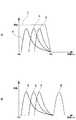
続いて、図3及び図4を参照して、対応点探査部31による対応点探索処理の例について説明する。図3は、可視光線の波長成分のみを含む第1の画像信号S1の輝度値I1と、赤外線の波長成分も含む第2の画像信号S2の輝度値I2とを、1次元空間の座標上にプロットしたグラフである。ここでは、x座標にプロットした例を示している。図3の縦軸は輝度値I(x)を示し、横軸はx座標を示す。図3において、可視光線の波長成分のみを含む第1の画像信号S1の輝度値I1は実線で示してあり、赤外線の波長成分も含む第2の画像信号S2の輝度値I2は破線で示してある。<2. Example of corresponding point search processing>
Next, an example of corresponding point search processing by the corresponding
図3に示されるように、輝度値I1と輝度値I2とではほぼ同一の分布形状となっており、赤外線の波長成分も含む輝度値I2の分布形状が、赤外線の波長成分を含まない輝度値I1の分布形状に対して全体的に上方にずれている。すなわち、両輝度値Iは輝度値の方向にずれを有しているものの、互いに高い相関性を有していることが分かる。As shown in FIG. 3, the luminance value I1 and the luminance value I2 have substantially the same distribution shape, and the distribution shape of the luminance value I2 including the infrared wavelength component includes the infrared wavelength component. It is generally shifted upward with respect to no luminance value I1 of the distribution shape. That is, it can be seen that although both luminance values I have a deviation in the direction of the luminance value, they have a high correlation with each other.
このような輝度値I1と輝度値I2との対応点は、正規化相関法を用いて探査することが可能である。図4は、正規化相関法の概略を説明した図である。正規化相関法では、図4の上側に示す画像P1中の観測点p1との相関が最も高い対応点p2を、図4の下側に示す画像P2中から探査することを行う。Such corresponding points between the luminance value I1 and the luminance value I2 can be searched using the normalized correlation method. FIG. 4 is a diagram for explaining the outline of the normalized correlation method. The normalized correlation method is performed to search the corresponding point p2 is the highest correlation with the observation point p1 in the image P1 shown on the upper side of FIG. 4, from the image P2 shown in the lower part of FIG. 4 .
より詳細には、観測点p1の周辺の局所画像と、対応点p2の候補としての点x2周辺の局所画像との類似度の度合いを示す相関係数ρを、点x2の位置を動かしながら都度算出する。そして、相関関数ρの値が最も高かった点x2を、対応点p2として採用する。局所画像のサイズは、横(2n+1)×縦(2m+1)であるものとする。観測点p1と点x2(対応点p2)との相関係数ρは、以下の数1に示す式で算出できる。More specifically, the correlation coefficient ρ indicating the degree of similarity between the local image around the observation point p1 and the local image around the point x2 as a candidate for the corresponding point p2 is represented by the position of the point x2 . Calculate each time while moving. Then, the point x2 having the highest correlation function ρ value is adopted as the corresponding point p2 . It is assumed that the size of the local image is horizontal (2n + 1) × vertical (2m + 1). The correlation coefficient ρ between the observation point p1 and the point x2 (corresponding point p2 ) can be calculated by the following equation (1 ).

上記数1において、“u1”,“v1”はそれぞれ観測点p1のx座標とy座標を示し、I1は、座標(u1+i,v1+j)の画素の輝度値を示す。また、“u2”,“v2”はそれぞれ対応点p2(点x2)のx座標とy座標を示し、I2は、座標(u2+i,v2+j)の画素の輝度値を示す。上記数1における“μp1”は観測点p1の周辺の局所画像における輝度値I1の平均値を示す。“μp2”は対応点p2の周辺の局所画像における各画素の輝度値I2の平均値を示す。“σp1”は観測点p1の周辺の局所画像における各画素の輝度値I1の標準偏差を示す。“σp2”は対応点p2の周辺の局所画像における輝度値I2の標準偏差を示す。In Equation1 , “u1 ” and “v1 ” indicate the x coordinate and y coordinate of the observation point p1 , respectively, and I1 indicates the luminance value of the pixel at the coordinates (u1 + i, v1 + j). Show. “U2 ” and “v2 ” indicate the x and y coordinates of the corresponding point p2 (point x2 ), respectively, and I2 indicates the luminance of the pixel at the coordinates (u2 + i, v2 + j). Indicates the value. “Μp1 ” in the above equation1 represents an average value of the luminance values I1 in the local image around the observation point p1 . “Μp2 ” indicates an average value of the luminance values I2 of the respective pixels in the local image around the corresponding point p2 . “Σp1 ” indicates the standard deviation of the luminance value I1 of each pixel in the local image around the observation point p1 . “Σp2 ” indicates the standard deviation of the luminance value I2 in the local image around the corresponding point p2 .
数1に示した正規化相関法を用いることで、輝度値のレベル方向にずれを有する、赤外線の波長成分を有する輝度値I2と、赤外線の波長成分を持たない輝度値I1との対応点p2も、探査することができる。Correspondence between the luminance value I2 having the infrared wavelength component and the luminance value I1 not having the infrared wavelength component, which has a deviation in the level direction of the luminance value, by using the normalized correlation method shown in Formula1. pointp 2 may also be probed.
上述した実施形態例によれば、IRCF12が配置されない撮像素子2bで撮影された画像信号S2から、輝度信号が生成される。すなわち、低照度の環境下では撮影できないような被写体も、赤外線の波長成分として撮像素子2b内に取り込むことができる。したがって、高感度な撮影を行えるようになる。According to the embodiment example described above, the image signal S2, which is captured by the
また、低照度環境下で撮影が行われた際には、赤外線の波長帯にも感度を有する撮像素子2bで生成される画像信号S2は、赤外光の分だけ輝度値が高くなる。これにより、輝度値を引き上げるための信号処理を行わずに済むため、画像信号S2のS/Nも良くなる。さらに、画像信号のS/Nが良くなることで、ノイズ除去フィルタを強くかける必要もなくなる。よって、高精細で低ノイズな3次元画像を得ることが可能となる。Also, when shooting under low illumination environment is performed, the image signal S2, which is generated by the
また、上述した実施形態例によれば、赤外線の波長成分を含まない画像信号S1から色信号が生成されるため、生成される3次元画像の色再現性が良好に保たれる。すなわち、本実施形態例によれば、高感度で色再現性の高い3次元画像が提供される。Further, according to the embodiment example described above, since the color signal from the image signals S1 does not contain a wavelength component of the infrared rays are generated, the color reproducibility of the three-dimensional image generated is kept good. That is, according to this embodiment, a three-dimensional image with high sensitivity and high color reproducibility is provided.
つまり、本実施の形態例によれば、外部に赤外LEDなどの投光装置を追加したり、三次元複眼カメラの構成を変更したりすることなく、撮像素子2b(及び撮像素子2a)の構成と信号処理内容のみを変更することで、高感度で色再現性の高い3次元画像を得られるようになる。 That is, according to the present embodiment, the
また、上述した実施形態例によれば、撮像素子2aの前面にはIRCF12が配置されないため、撮像素子2aが赤外線の波長成分に対する感度を有するものとなる。これにより、低照度の環境下においても、被写体を撮影することが可能となる。 Further, according to the above-described embodiment, since the
このとき、赤外LED(Light Emitting Diode)等の赤外線投射装置を用いて撮影時に被写体に補助光を照射することで、非常に低照度な環境下においても3次元画像の撮影を行えるようになる。赤外線投射装置としては、850nm近辺や950nm近辺の波長を照射する装置が比較的多く使用されており、例えば、このような赤外線投射装置を使用することができる。 At this time, by using an infrared projection device such as an infrared LED (Light Emitting Diode) to irradiate the subject with auxiliary light at the time of photographing, it becomes possible to photograph a three-dimensional image even in a very low illumination environment. . As an infrared projection device, a device that irradiates a wavelength around 850 nm or around 950 nm is used relatively frequently. For example, such an infrared projection device can be used.
<3.各種変形例>
なお、上述した実施形態例では、IRCF12のカットオフ周波数を650nmとしたが、この周波数に限定されるものではなく、撮像素子2bの分光感度特性や撮影環境に応じて他の周波数を適用してもよい。<3. Various modifications>
In the above-described embodiment, the cutoff frequency of the
また、上述した実施形態例では、撮像素子2bの前面にIRCF12を設けないことで、撮像素子2bの分光感度特性を、赤外線の帯域にも感度を有するものとした。しかし、これに限定されるものではなく、撮像素子2bの前面に、可視光線と、赤外線の所定の帯域の光の両方を通過させるIRCF(第2のフィルタ)を設けてもよい。 In the above-described embodiment, the
図5は、第2のフィルタとしてのIRCF12αのフィルタ特性Cαと、撮像素子2bの分光感度特性を示すグラフである。IRCF12αは、図5に示すように、例えば650nm以下の帯域と、820nm〜870nmの赤外線の帯域の両方の光を通過させるフィルタ特性Cαを有する。このIRCF12αが取り付けられた撮像素子2bには、波長が650nm以下の可視光線と、820nm〜870nmの帯域の赤外線が入射する。言い換えると、650nm〜820nmの近赤外線の波長帯の光は、撮像素子2bには入射されない。 FIG. 5 is a graph showing the filter characteristic Cα of the IRCF 12α as the second filter and the spectral sensitivity characteristic of the
図5に示すように、この650nm〜820nmの波長帯は、R,G,Bのすべての光に対して感度があり、かつその感度が低い波長帯である。この波長帯の光を遮断することで、撮像素子2bで生成される画像信号S2の色再現性は向上する。また、赤外LEDの補助光をすることを前提に、IRCF12αが通過する波長帯を設定すれば、赤外LEDによる補助光を効果的に用いることが可能となる。つまり、IRCF12αのフィルタ特性Cαを、撮像素子2bの分光感度特性や、使用する赤外LEDの発光スペクトルに応じて適切な特性に設定することができる。As shown in FIG. 5, the wavelength band of 650 nm to 820 nm is a wavelength band that is sensitive to all light of R, G, and B and has low sensitivity. This By blocking the light in a wavelength band, the color reproducibility of an image signal S2 generated by the
図6は、IRCF12αが使用される撮像装置10αの構成例を示すブロック図である。図6において、図1と対応する箇所には同一の符号を付してあり、重複する説明は省略する。図6に示す構成では、IRCF12αが取り付けられた撮像素子2bαで生成された画像信号S2も、色信号生成部4に入力される。つまり、撮像素子2bαの分光感度特性における、R,G,Bのすべての光に対して感度があり、かつその感度が低い波長帯の光がカットされた画像信号S2から色信号が生成されるため、色再現性が向上する。FIG. 6 is a block diagram illustrating a configuration example of the imaging device 10α in which the IRCF 12α is used. 6, portions corresponding to those in FIG. 1 are denoted by the same reference numerals, and redundant description is omitted. In the configuration illustrated in FIG. 6, the image signal S2 generated by the
また、撮像素子2bαの前面にもIRCF12αを設けることで、撮像素子2aと撮像素子2bαの分光感度特性が、図1に示した構成におけるそれよりもさらに揃う。これにより、色再現性をさらに向上させることができる。 Further, by providing the IRCF 12α also on the front surface of the image pickup device 2bα, the spectral sensitivity characteristics of the image pickup device 2a and the image pickup device 2bα are further aligned with those in the configuration shown in FIG. Thereby, color reproducibility can be further improved.
また、相関検出部3において、画像信号S2に対して赤外線の成分をキャンセルする減色信号補正処理(カラーマトリクス処理)をさらに施してもよい。この処理を行うことにより、画像信号S1よりなる画像P1と、画像信号S2よりなる画像P2におけるR,G,Bの色再現性をさらに揃えることが可能となるため、色再現性の更なる向上を図ることができる。Further, the
なお、本開示は以下のような構成も取ることができる。
(1)可視光線の波長より長い所定の波長帯の光を透過しない第1のフィルタを通して入射した被写体光を光電変換して、第1の画像信号を出力する第1の撮像素子と、
前記第1の撮像素子とは異なる位置に配置され、前記所定の波長帯の光の波長成分を含む被写体光を光電変換して、第2の画像信号を出力する第2の撮像素子と、
前記第1の画像信号と前記第2の画像信号の相関を検出する相関検出部と、
前記第2の画像信号から輝度信号を生成する輝度信号生成部と、
前記第1の画像信号及び/又は前記第2の画像信号から色信号を生成する色信号生成部と、
前記相関検出部で検出された前記相関の情報と、前記輝度信号と前記色信号とを用いて、3次元画像を生成する3次元画像生成部とを備えた撮像装置。
(2)前記第1の撮像素子は、前記第1のフィルタを通して入射した、赤外線の波長帯の光を含まない被写体光を光電変換して、前記第1の画像信号を生成する(1)に記載の撮像装置。
(3)前記相関検出部は、正規化相関法を用いて前記第1の画像信号と前記第2の画像信号の相関を検出する(1)又は(2)に記載の撮像装置。
(4)前記第1の撮像素子は、前記第1のフィルタとしての赤外カットフィルタを通して入射された被写体光から前記第1の画像信号を生成する。(1)〜(3)のいずれかに記載の撮像装置。
(5)前記第2の撮像素子は、近赤外線の波長帯のうちの所定の波長帯の光を遮断する第2のフィルタを通して入射した被写体光から、前記第2の画像信号を生成する(1)〜(4)のいずれかに記載の撮像装置。
(6)前記第2の撮像素子は、前記第2のフィルタを通して入射した、当該第2の撮像素子の分光感度特性におけるR,G,Bのすべての光に対して感度があり、かつその感度が低い波長帯の光を含まない被写体光から、前記第2の画像信号を生成する(5)に記載の撮像装置。
(7)第1の撮像素子が、可視光線の波長より長い所定の波長帯の光を透過しない第1のフィルタを通して入射した被写体光を光電変換して、第1の画像信号を出力することと、
前記第1の撮像素子とは異なる位置に配置された第2の撮像素子が、前記所定の波長帯の光の波長成分を含む被写体光を光電変換して第2の画像信号を出力することと、
前記第1の画像信号と前記第2の画像信号の相関を検出することと、
前記第2の画像信号から輝度信号を生成することと、
前記第1の画像信号及び/又は前記第2の画像信号から色信号を生成することと、
前記検出された相関の情報と、前記輝度信号と前記色信号とを用いて、3次元画像を生成することとを含む撮像方法。In addition, this indication can also take the following structures.
(1) a first image sensor that photoelectrically converts subject light incident through a first filter that does not transmit light in a predetermined wavelength band longer than the wavelength of visible light, and outputs a first image signal;
A second imaging element that is disposed at a position different from the first imaging element, photoelectrically converts subject light including a wavelength component of light in the predetermined wavelength band, and outputs a second image signal;
A correlation detection unit for detecting a correlation between the first image signal and the second image signal;
A luminance signal generation unit that generates a luminance signal from the second image signal;
A color signal generation unit that generates a color signal from the first image signal and / or the second image signal;
An imaging apparatus comprising: a three-dimensional image generation unit configured to generate a three-dimensional image using the correlation information detected by the correlation detection unit, the luminance signal, and the color signal.
(2) The first image sensor photoelectrically converts subject light that has entered through the first filter and does not include light in the infrared wavelength band, and generates the first image signal (1). The imaging device described.
(3) The imaging apparatus according to (1) or (2), wherein the correlation detection unit detects a correlation between the first image signal and the second image signal using a normalized correlation method.
(4) The first image pickup device generates the first image signal from subject light incident through an infrared cut filter as the first filter. The imaging device according to any one of (1) to (3).
(5) The second image sensor generates the second image signal from subject light incident through a second filter that blocks light in a predetermined wavelength band in the near-infrared wavelength band (1). ) To (4).
(6) The second image sensor is sensitive to all light of R, G, and B in the spectral sensitivity characteristic of the second image sensor that is incident through the second filter, and the sensitivity thereof. The imaging device according to (5), wherein the second image signal is generated from subject light that does not include light in a low wavelength band.
(7) the first imaging device photoelectrically converts the subject light incident through the first filter that does not transmit light in a predetermined wavelength band longer than the wavelength of visible light, and outputs a first image signal; ,
A second image sensor disposed at a position different from the first image sensor photoelectrically converts subject light including a wavelength component of light in the predetermined wavelength band and outputs a second image signal; ,
Detecting a correlation between the first image signal and the second image signal;
Generating a luminance signal from the second image signal;
Generating a color signal from the first image signal and / or the second image signal;
An imaging method including generating a three-dimensional image using the detected correlation information, the luminance signal, and the color signal.
1a…第1の光学系、1b…第2の光学系、2a,2b…撮像素子、3…相関検出部、4…輝度信号生成部、5…色信号生成部、6…3次元画像生成部、7…表示部、10,10α…撮像装置、11a,11b…レンズ、12,12α…IRCF、31…対応点探査部、32…視差算出部 DESCRIPTION OF
Claims (7)
Translated fromJapanese前記第1の撮像素子とは異なる位置に配置され、前記所定の波長帯の光の波長成分を含む被写体光を光電変換して、第2の画像信号を出力する第2の撮像素子と、
前記第1の画像信号と前記第2の画像信号の相関を検出する相関検出部と、
前記第2の画像信号から輝度信号を生成する輝度信号生成部と、
前記第1の画像信号及び/又は前記第2の画像信号から色信号を生成する色信号生成部と、
前記相関検出部で検出された前記相関の情報と、前記輝度信号と前記色信号とを用いて、3次元画像を生成する3次元画像生成部とを備えた
撮像装置。A first image sensor that photoelectrically converts subject light incident through a first filter that does not transmit light in a predetermined wavelength band longer than the wavelength of visible light, and outputs a first image signal;
A second imaging element that is disposed at a position different from the first imaging element, photoelectrically converts subject light including a wavelength component of light in the predetermined wavelength band, and outputs a second image signal;
A correlation detection unit for detecting a correlation between the first image signal and the second image signal;
A luminance signal generation unit that generates a luminance signal from the second image signal;
A color signal generation unit that generates a color signal from the first image signal and / or the second image signal;
An imaging apparatus comprising: a three-dimensional image generation unit configured to generate a three-dimensional image using the correlation information detected by the correlation detection unit, the luminance signal, and the color signal.
請求項1に記載の撮像装置。2. The imaging according to claim 1, wherein the first imaging element photoelectrically converts subject light that has entered through the first filter and does not include light in an infrared wavelength band, and generates the first image signal. 3. apparatus.
請求項2に記載の撮像装置。The imaging apparatus according to claim 2, wherein the correlation detection unit detects a correlation between the first image signal and the second image signal using a normalized correlation method.
請求項3に記載の撮像装置。The imaging apparatus according to claim 3, wherein the first imaging element generates the first image signal from subject light incident through an infrared cut filter serving as the first filter.
請求項4に記載の撮像装置。5. The second image sensor generates the second image signal from subject light that has entered through a second filter that blocks light in a predetermined wavelength band of the near-infrared wavelength band. Imaging device.
請求項5に記載の撮像装置。The second image pickup device photoelectrically converts subject light that does not include light in a wavelength band that has a higher frequency at each of the R, G, and B wavelengths and is incident on the second filter. The imaging device according to claim 5, wherein the second image signal is generated.
前記第1の撮像素子とは異なる位置に配置された第2の撮像素子が、前記所定の波長帯の光の波長成分を含む被写体光を光電変換して第2の画像信号を出力することと、
前記第1の画像信号と前記第2の画像信号の相関を検出することと、
前記第2の画像信号から輝度信号を生成することと、
前記第1の画像信号及び/又は前記第2の画像信号から色信号を生成することと、
前記検出された相関の情報と、前記輝度信号と前記色信号とを用いて、3次元画像を生成することとを含む
撮像方法。The first image sensor photoelectrically converts the subject light incident through the first filter that does not transmit light in a predetermined wavelength band longer than the wavelength of visible light, and outputs a first image signal;
A second image sensor disposed at a position different from the first image sensor photoelectrically converts subject light including a wavelength component of light in the predetermined wavelength band and outputs a second image signal; ,
Detecting a correlation between the first image signal and the second image signal;
Generating a luminance signal from the second image signal;
Generating a color signal from the first image signal and / or the second image signal;
An imaging method, comprising: generating a three-dimensional image using the detected correlation information, the luminance signal, and the color signal.
Priority Applications (4)
| Application Number | Priority Date | Filing Date | Title |
|---|---|---|---|
| JP2013109476AJP2014230179A (en) | 2013-05-24 | 2013-05-24 | Imaging apparatus and imaging method |
| CN201410209169.8ACN104185006B (en) | 2013-05-24 | 2014-05-16 | Imaging device and imaging method |
| US14/281,117US9596454B2 (en) | 2013-05-24 | 2014-05-19 | Imaging apparatus and imaging method |
| US15/425,520US9979951B2 (en) | 2013-05-24 | 2017-02-06 | Imaging apparatus and imaging method including first and second imaging devices |
Applications Claiming Priority (1)
| Application Number | Priority Date | Filing Date | Title |
|---|---|---|---|
| JP2013109476AJP2014230179A (en) | 2013-05-24 | 2013-05-24 | Imaging apparatus and imaging method |
Publications (1)
| Publication Number | Publication Date |
|---|---|
| JP2014230179Atrue JP2014230179A (en) | 2014-12-08 |
Family
ID=51935126
Family Applications (1)
| Application Number | Title | Priority Date | Filing Date |
|---|---|---|---|
| JP2013109476APendingJP2014230179A (en) | 2013-05-24 | 2013-05-24 | Imaging apparatus and imaging method |
Country Status (3)
| Country | Link |
|---|---|
| US (2) | US9596454B2 (en) |
| JP (1) | JP2014230179A (en) |
| CN (1) | CN104185006B (en) |
Cited By (1)
| Publication number | Priority date | Publication date | Assignee | Title |
|---|---|---|---|---|
| JP2019009511A (en)* | 2017-06-20 | 2019-01-17 | キヤノン株式会社 | Distance information generating device, imaging device, distance information generating method, and program |
Families Citing this family (7)
| Publication number | Priority date | Publication date | Assignee | Title |
|---|---|---|---|---|
| KR20150022231A (en)* | 2013-08-22 | 2015-03-04 | 에스케이하이닉스 주식회사 | Three-dimensional image sensor module and materialization method for three-dimensional image using the same |
| FR3032297A1 (en)* | 2015-02-04 | 2016-08-05 | Stmicroelectronics (Grenoble 2) Sas | METHOD AND DEVICE FOR COMPRESSION OF A COLOR DIGITAL IMAGE |
| CN106170086B (en)* | 2016-08-19 | 2019-03-15 | 深圳奥比中光科技有限公司 | Method and device thereof, the system of drawing three-dimensional image |
| CN108076266A (en)* | 2016-11-11 | 2018-05-25 | 株式会社东芝 | Processing device and camera device |
| TWI669538B (en)* | 2018-04-27 | 2019-08-21 | 點晶科技股份有限公司 | Three-dimensional image capturing module and method for capturing three-dimensional image |
| CN110765537A (en)* | 2019-10-31 | 2020-02-07 | 耿宇峰 | Dental body dental pulp department layout simulation system and method |
| WO2024159126A1 (en)* | 2023-01-27 | 2024-08-02 | Cognex Corporation | High performance machine vision system |
Family Cites Families (50)
| Publication number | Priority date | Publication date | Assignee | Title |
|---|---|---|---|---|
| US6411377B1 (en)* | 1991-04-02 | 2002-06-25 | Hitachi, Ltd. | Optical apparatus for defect and particle size inspection |
| US5453611A (en)* | 1993-01-01 | 1995-09-26 | Canon Kabushiki Kaisha | Solid-state image pickup device with a plurality of photoelectric conversion elements on a common semiconductor chip |
| JPH07288824A (en)* | 1994-04-14 | 1995-10-31 | Asahi Optical Co Ltd | Luminance signal generator |
| JP3931392B2 (en)* | 1997-08-25 | 2007-06-13 | ソニー株式会社 | Stereo image video signal generating device, stereo image video signal transmitting device, and stereo image video signal receiving device |
| US5852753A (en)* | 1997-11-10 | 1998-12-22 | Lo; Allen Kwok Wah | Dual-lens camera with shutters for taking dual or single images |
| US7057647B1 (en)* | 2000-06-14 | 2006-06-06 | E-Watch, Inc. | Dual-mode camera system for day/night or variable zoom operation |
| US6157337A (en)* | 1999-01-29 | 2000-12-05 | Sony Corporation | 3D image acquiring and viewing systems and methods |
| JP2002197466A (en)* | 2000-12-27 | 2002-07-12 | Nec Corp | Object region extracting device, object region extracting method, and recording medium storing object region extracting program |
| JP4877891B2 (en)* | 2001-08-03 | 2012-02-15 | 株式会社トプコン | Calibration subject |
| KR100825172B1 (en)* | 2004-04-05 | 2008-04-24 | 미쓰비시덴키 가부시키가이샤 | Imaging device |
| JP4556722B2 (en)* | 2004-05-31 | 2010-10-06 | コニカミノルタホールディングス株式会社 | Imaging device |
| US7872665B2 (en)* | 2005-05-13 | 2011-01-18 | Micoy Corporation | Image capture and processing |
| US20070035628A1 (en)* | 2005-08-12 | 2007-02-15 | Kunihiko Kanai | Image-capturing device having multiple optical systems |
| WO2007060847A1 (en)* | 2005-11-22 | 2007-05-31 | Matsushita Electric Industrial Co., Ltd. | Imaging device |
| KR100739764B1 (en)* | 2005-11-28 | 2007-07-13 | 삼성전자주식회사 | Stereo image signal processing apparatus and method |
| US7567271B2 (en)* | 2006-01-09 | 2009-07-28 | Sony Corporation | Shared color sensors for high-resolution 3-D camera |
| JP2007295091A (en)* | 2006-04-21 | 2007-11-08 | Fujifilm Corp | Digital camera, digital camera system, and digital camera control program |
| JP5106870B2 (en)* | 2006-06-14 | 2012-12-26 | 株式会社東芝 | Solid-state image sensor |
| JP4983141B2 (en)* | 2006-08-04 | 2012-07-25 | ソニー株式会社 | Color filter |
| JP2008096584A (en)* | 2006-10-10 | 2008-04-24 | Nikon Corp | camera |
| US7978239B2 (en)* | 2007-03-01 | 2011-07-12 | Eastman Kodak Company | Digital camera using multiple image sensors to provide improved temporal sampling |
| US7676146B2 (en)* | 2007-03-09 | 2010-03-09 | Eastman Kodak Company | Camera using multiple lenses and image sensors to provide improved focusing capability |
| US7683962B2 (en)* | 2007-03-09 | 2010-03-23 | Eastman Kodak Company | Camera using multiple lenses and image sensors in a rangefinder configuration to provide a range map |
| US7859588B2 (en)* | 2007-03-09 | 2010-12-28 | Eastman Kodak Company | Method and apparatus for operating a dual lens camera to augment an image |
| US7729602B2 (en)* | 2007-03-09 | 2010-06-01 | Eastman Kodak Company | Camera using multiple lenses and image sensors operable in a default imaging mode |
| US8599247B2 (en)* | 2008-01-30 | 2013-12-03 | Samsung Electronics Co., Ltd. | Stereoscopic image system employing an electronic controller which controls the polarization plane rotator in synchronization with an output image of the display device |
| JP5040776B2 (en)* | 2008-03-31 | 2012-10-03 | アイシン精機株式会社 | Imaging device |
| US20100097444A1 (en)* | 2008-10-16 | 2010-04-22 | Peter Lablans | Camera System for Creating an Image From a Plurality of Images |
| US8629916B2 (en)* | 2008-08-19 | 2014-01-14 | Rohm Co., Ltd. | Camera with imaging unit and imaging unit for camera |
| KR101502603B1 (en)* | 2008-09-22 | 2015-03-13 | 삼성전자주식회사 | Stereoscopic image display device and method thereof |
| JP5332531B2 (en)* | 2008-11-18 | 2013-11-06 | ソニー株式会社 | Image display apparatus, image display method, and image display system |
| JP5167094B2 (en)* | 2008-11-28 | 2013-03-21 | 三星電子株式会社 | Imaging apparatus and imaging method |
| CN101833157A (en)* | 2009-03-13 | 2010-09-15 | 鸿富锦精密工业(深圳)有限公司 | Camera module |
| KR101638974B1 (en)* | 2009-06-17 | 2016-07-13 | 삼성전자주식회사 | Optical modulator, methods of manufacturing and operating the same and optical apparatus comprising optical modulator |
| JP5874116B2 (en)* | 2009-07-30 | 2016-03-02 | 国立研究開発法人産業技術総合研究所 | Image photographing apparatus and image photographing method |
| KR101616422B1 (en)* | 2009-12-23 | 2016-04-28 | 삼성전자주식회사 | Method and apparatus for processing the digital image by using fast AF |
| US20110175981A1 (en)* | 2010-01-19 | 2011-07-21 | Chun-Hung Lai | 3d color image sensor |
| JP5186517B2 (en) | 2010-02-25 | 2013-04-17 | シャープ株式会社 | Imaging device |
| US8896668B2 (en)* | 2010-04-05 | 2014-11-25 | Qualcomm Incorporated | Combining data from multiple image sensors |
| US8305485B2 (en)* | 2010-04-30 | 2012-11-06 | Eastman Kodak Company | Digital camera with coded aperture rangefinder |
| US9635349B2 (en)* | 2010-06-11 | 2017-04-25 | The Florida International University Board Of Trustees | Second generation hand held optical imager |
| US20120056982A1 (en)* | 2010-09-08 | 2012-03-08 | Microsoft Corporation | Depth camera based on structured light and stereo vision |
| JP5747083B2 (en)* | 2010-10-01 | 2015-07-08 | コンテックス・エー/エス | Two-dimensional calibration of image sensor alignment in optical scanner |
| KR101887099B1 (en)* | 2010-12-29 | 2018-08-09 | 삼성전자주식회사 | image processing system and image processing method |
| TWI405030B (en)* | 2011-02-23 | 2013-08-11 | Largan Precision Co Ltd | Imagery axle turning method for stereo vision and the apparatus thereof |
| US9161017B2 (en)* | 2011-08-11 | 2015-10-13 | Panasonic Intellectual Property Management Co., Ltd. | 3D image capture device |
| US9265186B2 (en)* | 2011-11-10 | 2016-02-16 | Delaware Capital Formation, Inc. | Camera system for aligning components of a PCB |
| US8896747B2 (en)* | 2012-11-13 | 2014-11-25 | Qualcomm Technologies, Inc. | Depth estimation based on interpolation of inverse focus statistics |
| US20140347350A1 (en)* | 2013-05-23 | 2014-11-27 | Htc Corporation | Image Processing Method and Image Processing System for Generating 3D Images |
| US9854157B1 (en)* | 2016-10-04 | 2017-12-26 | Gopro, Inc. | Camera with touch sensor integrated with lens window |
- 2013
- 2013-05-24JPJP2013109476Apatent/JP2014230179A/enactivePending
- 2014
- 2014-05-16CNCN201410209169.8Apatent/CN104185006B/ennot_activeExpired - Fee Related
- 2014-05-19USUS14/281,117patent/US9596454B2/ennot_activeExpired - Fee Related
- 2017
- 2017-02-06USUS15/425,520patent/US9979951B2/ennot_activeExpired - Fee Related
Cited By (2)
| Publication number | Priority date | Publication date | Assignee | Title |
|---|---|---|---|---|
| JP2019009511A (en)* | 2017-06-20 | 2019-01-17 | キヤノン株式会社 | Distance information generating device, imaging device, distance information generating method, and program |
| JP7009091B2 (en) | 2017-06-20 | 2022-01-25 | キヤノン株式会社 | Distance information generator, image pickup device, distance information generation method, and program |
Also Published As
| Publication number | Publication date |
|---|---|
| US9979951B2 (en) | 2018-05-22 |
| CN104185006A (en) | 2014-12-03 |
| US20170150125A1 (en) | 2017-05-25 |
| US20140347449A1 (en) | 2014-11-27 |
| CN104185006B (en) | 2017-12-12 |
| US9596454B2 (en) | 2017-03-14 |
Similar Documents
| Publication | Publication Date | Title |
|---|---|---|
| US9979951B2 (en) | Imaging apparatus and imaging method including first and second imaging devices | |
| CN103477186B (en) | Stereo camera | |
| CN102959970B (en) | Device, method and program for determining obstacles within imaging range during stereoscopic display imaging | |
| US10015472B2 (en) | Image processing using distance information | |
| TWI525382B (en) | Camera array systems including at least one bayer type camera and associated methods | |
| JP2021073722A (en) | Imaging element and electronic device | |
| US20170034499A1 (en) | Structured-stereo imaging assembly including separate imagers for different wavelengths | |
| US9743065B2 (en) | Method and apparatus generating color and depth images | |
| US10335019B2 (en) | Image pickup element and endoscope device | |
| US11930282B2 (en) | Control device, control method, and electronic device to determine a lens position | |
| KR20170094968A (en) | Member for measuring depth between camera module, and object and camera module having the same | |
| CN105338263B (en) | Image sensor and image pickup apparatus including the same | |
| JP2019054463A5 (en) | ||
| KR102283423B1 (en) | Image pick-up apparatus, portable terminal including the same and image pick-up method using the apparatus | |
| CN110574368B (en) | Solid-state cameras, camera systems, and object recognition systems | |
| US9544570B2 (en) | Three-dimensional image pickup apparatus, light-transparent unit, image processing apparatus, and program | |
| JP2009290268A (en) | Imaging apparatus | |
| WO2018150925A1 (en) | Focus detection device, focus detection method, and focus detection program | |
| JP6426753B2 (en) | Imaging system | |
| CN107427264A (en) | Camera device, image processing device and image processing method | |
| US20170214890A1 (en) | Image processing apparatus, image processing method, and imaging apparatus | |
| US11589028B2 (en) | Non-same camera based image processing apparatus | |
| JP2010276469A (en) | Image processor and image processing method of ranging apparatus | |
| JPWO2009017184A1 (en) | Color imaging device, imaging device using the same, and filter | |
| US20150116500A1 (en) | Image pickup apparatus |