JP2014225832A - Signal amplification device, distortion compensation method and radio transmission device - Google Patents
Signal amplification device, distortion compensation method and radio transmission deviceDownload PDFInfo
- Publication number
- JP2014225832A JP2014225832AJP2013105001AJP2013105001AJP2014225832AJP 2014225832 AJP2014225832 AJP 2014225832AJP 2013105001 AJP2013105001 AJP 2013105001AJP 2013105001 AJP2013105001 AJP 2013105001AJP 2014225832 AJP2014225832 AJP 2014225832A
- Authority
- JP
- Japan
- Prior art keywords
- amplifier
- model
- inverse
- gain value
- inverse gain
- Prior art date
- Legal status (The legal status is an assumption and is not a legal conclusion. Google has not performed a legal analysis and makes no representation as to the accuracy of the status listed.)
- Granted
Links
Images


Landscapes
- Amplifiers (AREA)
- Transmitters (AREA)
Abstract
Description
Translated fromJapanese本発明は、増幅器の歪み補償技術であるデジタルプリディストーションを備えた信号増幅装置とその歪み補償方法及びこれを用いた無線送信装置に関する。 The present invention relates to a signal amplifying apparatus having a digital predistortion that is a distortion compensation technique of an amplifier, a distortion compensation method thereof, and a radio transmission apparatus using the same.
無線送信装置に使用する増幅器は、高効率で低歪みな信号増幅が望まれる。増幅器の非線形増幅特性を補償して低歪みを実現する技術としては、デジタルプリディストーション(Digital Pre−distortion、以下、DPDと略す)が知られている。DPDは、増幅器に入力する信号を、デジタル処理によって予め歪ませることにより、増幅器による歪みを打ち消して低歪みな増幅を実現する方式である。 An amplifier used in a wireless transmission device is desired to have high efficiency and low distortion signal amplification. Digital pre-distortion (hereinafter abbreviated as DPD) is known as a technique for realizing low distortion by compensating for the nonlinear amplification characteristics of an amplifier. DPD is a method for realizing low distortion amplification by distorting a signal input to an amplifier in advance by digital processing, thereby canceling distortion caused by the amplifier.
DPDの構成方法は、大きく分けてDLA(direct learning architectures)とILA(indirect learning algorithm)との2通りがあり、それぞれ非特許文献1と非特許文献2とに開示されている。 The DPD configuration method is roughly divided into two types, DLA (direct learning architectures) and ILA (direct learning algorithm), which are disclosed in Non-Patent Document 1 and Non-Patent
図3は、DLAによる既存のDPDの構成を示す。DLAでは、まず、増幅器31の入力信号と出力信号とから、増幅器モデル部32において増幅器モデル(すなわち、増幅器の歪みモデル)を計算する。次に、増幅器逆モデル部33において、増幅器モデルとプリディストータ入力信号と増幅器出力信号とに基づいて、増幅器モデルの逆特性を持つ増幅器逆モデル(すなわち、逆歪みモデル)を計算する。次に、この増幅器逆モデルを元にプリディストータ34を構成する。プリディストータ入力信号にプリディストータ34による歪み補償を行うことで、プリディストータ34の入力信号と増幅器31の出力信号とが線形になり、線形な増幅が実現する。 FIG. 3 shows the configuration of an existing DPD using DLA. In DLA, first, an amplifier model (that is, an amplifier distortion model) is calculated in the
なお、最初のプリディストータ入力信号は、歪み補償はされない。すなわち、プリディストータ入力信号と増幅器入力信号とは同じとなる。上記の処理により、増幅器モデルと増幅器逆モデルが正しいモデルに収束するに伴って、プリディストータ34はプリディストータ入力信号に正しい歪み補償を行うようになる。 Note that the first predistorter input signal is not subjected to distortion compensation. That is, the predistorter input signal and the amplifier input signal are the same. With the above processing, as the amplifier model and the amplifier inverse model converge to the correct model, the
DLAでは、増幅器31の歪みモデルを元に逆歪みモデルを決めることから、高い歪み補償効果を安定に得られる。一方で、増幅器モデルと増幅器逆モデルの2種類のモデルを計算する必要があることから、計算量が多くなるという問題がある。 In DLA, since the inverse distortion model is determined based on the distortion model of the
図4は、ILAによる既存のDPDの構成を示す。ILAでは、増幅器41の入力信号と出力信号とにおいて、出力信号を入力信号に、入力信号を出力信号に見なして、増幅器逆モデル部43において、増幅器逆モデル(すなわち、逆歪みモデル)を計算する。次に、この増幅器逆モデルのパラメータを元にプリディストータ44を構成する。 FIG. 4 shows the configuration of an existing DPD based on ILA. In the ILA, regarding the input signal and output signal of the
ILAをDLAと比べると、ILAでは、増幅器モデル部を必要とせず、増幅器逆モデルの1種類のモデルの計算で済むことから、計算量が少なくなるという利点を持つ。一方で、ILAでは、増幅器自身の歪みモデルを持たない簡略的な方法であることから、DLAと比べて歪み補償効果が低い。また、増幅器が出力飽和している状態においては、増幅器逆モデルのパラメータが不安定になり、正しく歪補償ができなくなる場合があるという問題がある。 Compared with DLA, ILA does not require an amplifier model part, and has only one calculation of an inverse model of the amplifier, and therefore has the advantage of reducing the amount of calculation. On the other hand, since ILA is a simple method that does not have a distortion model of the amplifier itself, the distortion compensation effect is lower than that of DLA. In addition, when the output of the amplifier is saturated, the parameters of the amplifier inverse model become unstable, and there is a problem that distortion compensation cannot be performed correctly.
以上のように、既存のDPDの構成方法においては、計算量と歪み補償効果にはトレードオフの関係がある。さらには、DLAやILAにおける増幅器モデルやプリディストータといった個々の構成要素においても、計算量と歪み補償効果にトレードオフの関係が存在している。以下、これについて述べる。 As described above, in the existing DPD configuration method, there is a trade-off relationship between the calculation amount and the distortion compensation effect. Furthermore, there is a trade-off relationship between the calculation amount and the distortion compensation effect even in individual components such as amplifier models and predistorters in DLA and ILA. This will be described below.
増幅器モデルを構成する際に良く知られている方法は、増幅器の入力信号の振幅成分と出力信号の振幅成分との特性を示すAMAM特性と、増幅器の入力信号の振幅成分と増幅器の入出力信号の位相誤差を示すAMPM特性とを、統計的に抽出する方法である。これらの統計的な抽出は、増幅器の入力信号の振幅成分に基づいたLUT(Look Up Table)を用いることで実現される。また、増幅器の入出力信号を複素信号として扱う場合は、ボルテラ級数を用いた入力信号の非線形多項式フィルタによって実現される。 A well-known method for constructing an amplifier model is an AMAM characteristic indicating the characteristics of the amplitude component of the input signal of the amplifier and the amplitude component of the output signal, the amplitude component of the input signal of the amplifier, and the input / output signal of the amplifier. This is a method of statistically extracting the AMPM characteristic indicating the phase error of the. These statistical extractions are realized by using a LUT (Look Up Table) based on the amplitude component of the input signal of the amplifier. Further, when the input / output signal of the amplifier is handled as a complex signal, it is realized by a nonlinear polynomial filter of the input signal using a Volterra series.
上記の増幅器モデルのAMAM特性とAMPM特性の抽出方法は、そのままプリディストータとして用いることができる。その場合、プリディストータの入力信号を、増幅器モデルのAMAM特性とAMPM特性の逆特性を持つLUTまたは非線形多項式フィルタによって予め作用させ、この信号を増幅器に入力する。これにより、プリディストータの入力信号に対して、増幅器の出力信号が線形になり、低歪みの増幅が可能となる。上記の方法で行われるAMAM特性とAMPM特性とによる歪み補償は、一般にメモリレスDPDと呼ばれている。 The AMAM characteristic and AMPM characteristic extraction method of the amplifier model can be used as it is as a predistorter. In that case, the input signal of the predistorter is acted in advance by an LUT or a nonlinear polynomial filter having an inverse characteristic of the AMAM characteristic and the AMPM characteristic of the amplifier model, and this signal is input to the amplifier. As a result, the output signal of the amplifier becomes linear with respect to the input signal of the predistorter, and amplification with low distortion becomes possible. Distortion compensation by AMAM characteristics and AMPM characteristics performed by the above method is generally called memoryless DPD.
メモリレスDPDにより、増幅器の持つ統計的なAMAM特性とAMPM特性は補償可能である。しかしながら、増幅器の歪み特性は、メモリレスDPDだけでは信号の歪み規格値を満たさない場合も多く存在している。その場合、増幅器モデルやプリディストータの構成としては、統計的なAMAM特性とAMPM特性とを抽出するだけでは不十分である。 The statistical AMAM characteristic and AMPM characteristic of the amplifier can be compensated by the memoryless DPD. However, there are many cases where the distortion characteristics of an amplifier do not satisfy the signal distortion standard value only with the memoryless DPD. In that case, it is not sufficient to extract statistical AMAM characteristics and AMPM characteristics as the configuration of the amplifier model and predistorter.
メモリレスDPDよりも、高い歪み補償効果を実現するためには、増幅器のメモリ効果を、増幅器モデルおよびプリディストータに組み込む必要がある。増幅器のメモリ効果とは、増幅器の出力信号の歪みが、その出力信号に同期した入力信号だけに依存せずに、その入力信号の過去の入力信号の経歴にも影響される現象である。 In order to realize a higher distortion compensation effect than the memoryless DPD, it is necessary to incorporate the memory effect of the amplifier into the amplifier model and the predistorter. The memory effect of the amplifier is a phenomenon in which the distortion of the output signal of the amplifier does not depend only on the input signal synchronized with the output signal but is also influenced by the history of the input signal in the past.
DPDの構成において、メモリレスDPDよりも歪み補償効果を高めるためには、上記のメモリ効果を加味した増幅器モデルおよびプリディストータを構成する必要がある。具体的には、増幅器モデルの非線形多項式フィルタにタップを追加することにより、ある時間の出力信号が、同期したある時間の入力信号だけでなく、その過去の入力信号値によっても影響される形に置き換えることができる。 In the DPD configuration, in order to enhance the distortion compensation effect as compared with the memoryless DPD, it is necessary to configure an amplifier model and a predistorter in consideration of the memory effect. Specifically, by adding a tap to the nonlinear polynomial filter of the amplifier model, the output signal of a certain time is affected not only by the synchronized input signal of a certain time but also by the past input signal value. Can be replaced.
プリディストータも同様に、上記のメモリ効果を含んだ増幅器モデルの逆特性を実現するために、フィルタにタップを追加して、過去の入力信号の値も影響を与える形で補償を行う。この方法によって行われる歪み補償は、一般にメモリ効果補償DPDと呼ばれる。 Similarly, in order to realize the inverse characteristic of the amplifier model including the memory effect described above, the predistorter is also compensated by adding a tap to the filter and affecting the value of the past input signal. Distortion compensation performed by this method is generally called memory effect compensation DPD.
DPDを構成するDLAとILAのどちらの方法においても、メモリ効果補償DPDは、メモリレスDPDと比べて歪み補償効果が高い。しかしながら、タップを増やすことに応じて、増幅器モデルやプリディストータのパラメータが増える。さらに、パラメータ演算のアルゴリズムが複雑化する。以上のことから、メモリ効果補償DPDでは計算量が増大してしまうという問題があった。 In both the DLA and ILA methods constituting the DPD, the memory effect compensation DPD has a higher distortion compensation effect than the memoryless DPD. However, as the number of taps increases, the parameters of the amplifier model and predistorter increase. Furthermore, the algorithm for parameter calculation becomes complicated. From the above, the memory effect compensation DPD has a problem that the calculation amount increases.
歪み補償送信機としては、近年、ますます高い歪み補償効果と、プリディストータを構成するための計算の安定性が要求されていることから、歪み補償アルゴリズムの構成としては、DLAが望ましい場合が多い。しかしながら、DLAは上記の通り、その歪み補償効果をより高めるためには、より正確な増幅器モデルと増幅器逆モデルを構成する必要がある。すなわち、メモリ効果を考慮した歪み補償を行うために、タップを含んだ非線形多項式フィルタを、増幅器モデルと増幅器逆モデルとで2種類構成する必要がある。これにより、DLAでは計算量が膨大となり問題となっていた。 In recent years, distortion compensation transmitters are required to have a higher distortion compensation effect and stability of calculation for configuring a predistorter. Therefore, DLA may be desirable as a configuration of a distortion compensation algorithm. Many. However, as described above, in order to further enhance the distortion compensation effect of DLA, it is necessary to construct a more accurate amplifier model and amplifier inverse model. That is, in order to perform distortion compensation in consideration of the memory effect, it is necessary to configure two types of nonlinear polynomial filters including taps, an amplifier model and an amplifier inverse model. As a result, the amount of calculation in DLA becomes enormous, which is a problem.
以上のことから、増幅器のメモリ効果を取り込んだ歪み補償アルゴリズムにおいて、DLAと同等の歪み補償効果と計算の安定性を保持しつつ、DLAよりも計算量が少ないDPDの構成方法が望まれている。 From the above, in a distortion compensation algorithm that incorporates the memory effect of an amplifier, a DPD configuration method that requires a calculation amount smaller than that of DLA while maintaining the same distortion compensation effect and calculation stability as DLA is desired. .
本発明は、上記の課題に鑑みてなされたものであり、その目的は、増幅器の歪み補償技術であるデジタルプリディストーションを備えた信号増幅装置において、高い歪み補償効果を安定した少ない計算量で実現する信号増幅装置とその歪み補償方法及びこれを用いた無線送信装置を提供することにある。 The present invention has been made in view of the above-mentioned problems, and its object is to realize a high distortion compensation effect with a stable and small amount of calculation in a signal amplifying apparatus having a digital predistortion which is a distortion compensation technique of an amplifier. It is an object of the present invention to provide a signal amplifying device, a distortion compensation method thereof, and a wireless transmission device using the same.
本発明による信号増幅装置は、増幅器と、前記増幅器の歪み補償を行うプリディストータと、前記増幅器の歪み特性を表す増幅器モデルのパラメータと前記歪み特性の逆特性を表すモデル逆利得値とを算出する増幅器モデル部と、前記モデル逆利得値を平均化した平均逆利得値を算出する逆利得処理部と、前記平均逆利得に基づいた増幅器逆モデルのパラメータを算出する増幅器逆モデル部と、を有し、前記プリディストータは、前記増幅器逆モデルのパラメータに基づいて前記プリディストータのパラメータを決定し前記歪み補償を行うことを特徴とする。 A signal amplifying apparatus according to the present invention calculates an amplifier, a predistorter that performs distortion compensation of the amplifier, an amplifier model parameter that represents the distortion characteristic of the amplifier, and a model inverse gain value that represents the inverse characteristic of the distortion characteristic. An amplifier model unit, an inverse gain processing unit that calculates an average inverse gain value obtained by averaging the model inverse gain values, and an amplifier inverse model unit that calculates parameters of the amplifier inverse model based on the average inverse gain. And the predistorter performs the distortion compensation by determining a parameter of the predistorter based on a parameter of the amplifier inverse model.
本発明による歪み補償方法は、増幅器の歪み特性を表す増幅器モデルのパラメータから前記歪み特性の逆特性を表すモデル逆利得値を算出し、前記モデル逆利得値を平均化した平均逆利得値を算出し、前記平均逆利得に基づいた増幅器逆モデルのパラメータを算出し、前記増幅器逆モデルのパラメータに基づいて前記増幅器の歪み補償を行うプリディストータのパラメータを決定し、前記歪み補償を行うことを特徴とする。 The distortion compensation method according to the present invention calculates a model inverse gain value that represents the inverse characteristic of the distortion characteristic from an amplifier model parameter that represents the distortion characteristic of the amplifier, and calculates an average inverse gain value obtained by averaging the model inverse gain value. Calculating a parameter of the amplifier inverse model based on the average inverse gain, determining a predistorter parameter for performing distortion compensation of the amplifier based on the parameter of the amplifier inverse model, and performing the distortion compensation. Features.
本発明による無線送信装置は、増幅器と、前記増幅器の歪み補償を行うプリディストータと、前記増幅器の歪み特性を表す増幅器モデルのパラメータと前記歪み特性の逆特性を表すモデル逆利得値とを算出する増幅器モデル部と、前記モデル逆利得値を平均化した平均逆利得値を算出する逆利得処理部と、前記平均逆利得に基づいた増幅器逆モデルのパラメータを算出する増幅器逆モデル部と、を有し、前記プリディストータは、前記増幅器逆モデルのパラメータに基づいて前記プリディストータのパラメータを決定し前記歪み補償を行う信号増幅装置を備えたことを特徴とする。 A radio transmission apparatus according to the present invention calculates an amplifier, a predistorter that performs distortion compensation of the amplifier, a parameter of an amplifier model that represents distortion characteristics of the amplifier, and a model inverse gain value that represents inverse characteristics of the distortion characteristics. An amplifier model unit, an inverse gain processing unit that calculates an average inverse gain value obtained by averaging the model inverse gain values, and an amplifier inverse model unit that calculates parameters of the amplifier inverse model based on the average inverse gain. And the predistorter includes a signal amplifying device that determines the predistorter parameters based on the parameters of the amplifier inverse model and performs the distortion compensation.
本発明の信号増幅装置及びこれを用いた無線送信装置によれば、増幅器の歪み補償技術であるデジタルプリディストーションを備えた信号増幅装置において、高い歪み補償効果を安定した少ない計算量で実現する信号増幅装置とその歪み補償方法及びこれを用いた無線送信装置を提供することが可能となる。 According to the signal amplifying device of the present invention and the wireless transmission device using the same, in the signal amplifying device having digital predistortion which is a distortion compensation technique of the amplifier, a signal that realizes a high distortion compensation effect with a stable and small amount of calculation. It is possible to provide an amplification device, a distortion compensation method thereof, and a wireless transmission device using the same.
以下、図を参照しながら、本発明の実施形態を詳細に説明する。但し、以下に述べる実施形態には、本発明を実施するために技術的に好ましい限定がされているが、発明の範囲を以下に限定するものではない。 Hereinafter, embodiments of the present invention will be described in detail with reference to the drawings. However, the preferred embodiments described below are technically preferable for carrying out the present invention, but the scope of the invention is not limited to the following.
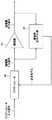
図1は、本発明の実施形態のデジタル歪み補償を備えた信号増幅装置の構成を示す図である。本実施形態の信号増幅装置1は、増幅器10と増幅器10の前段で増幅器10の歪みを補償するプリディストータ40とを備える。さらに、プリディストータ40のパラメータを決定するために、増幅器モデル部20と逆利得処理部50と増幅器逆モデル部30とを備える。 FIG. 1 is a diagram illustrating a configuration of a signal amplifying device including digital distortion compensation according to an embodiment of the present invention. The signal amplifying apparatus 1 according to the present embodiment includes an
増幅器モデル部20は、増幅器10の入力信号ziと出力信号yiとに基づいて、メモリレス増幅器モデル計算部20aにてメモリレス増幅器モデルを求める。さらに、メモリレス増幅器モデルのパラメータから、メモリレス増幅器モデルの表す歪みの逆特性を表すモデル逆利得値giを求める。The
メモリレス増幅器モデルのパラメータは、以下の手順により決定される。まず、メモリレス増幅器モデル計算部20aは、増幅器10の入力信号ziの振幅成分を元に、LUTなどにより構成されるメモリレス増幅器モデルのパラメータから、推定出力信号を算出する。次に、この推定出力信号と、入力信号ziと同期させた増幅器10の出力信号yiとの差を取る。そして、その差分が最小になるようにメモリレス増幅器モデルのパラメータを更新する。The parameters of the memoryless amplifier model are determined by the following procedure. First, the memoryless amplifier
なお増幅器10の出力信号yiおよび推定出力信号の値は、増幅器10による増幅分による差を見えなくして、歪み分の差の比較が出来るようにする。そのため、適宜両者の値を定数倍することで、増幅器10の増幅分による、値の増加の影響を打ち消すスケーリングを行う。The values of the output signal yi and the estimated output signal of the
メモリレス増幅器モデル計算部20aでは、増幅器10の入力信号の過去の履歴に影響されずに出力信号をモデル化することから、計算量が少なく、LUTや非線形多項式フィルタなどによって簡単に実現される。そして、LUTや非線形多項式フィルタの有するパラメータの更新を継続することにより、増幅器10のデバイスの温度変化や経年劣化の影響を受けることなく、常に最新のパラメータで増幅器10の歪み特性を構成することが可能となる。 In the memoryless amplifier
すなわち、メモリレス増幅器モデル計算部20aでのメモリレス増幅器モデルのパラメータは、増幅器10が動作し続けている限り、入力信号ziと出力信号yiとに基づいて計算を続けることで、常に最新のパラメータで上記の更新が継続されることになる。ただし、パラメータの値の収束の程度によっては、更新の頻度を減らすことも可能であり、これにより計算量を減らすこともできる。In other words, the parameters of the memoryless amplifier model in the memoryless amplifier
増幅器モデル部20では、メモリレス増幅器モデル計算部20aにて更新したメモリレス増幅器モデルに基づいて、増幅器10の入力信号ziに対応するモデル逆利得値giを求める。モデル逆利得値giは、メモリレス増幅器モデルの表す歪みの逆特性を表す。The
逆利得処理部50では、増幅器10の入力信号ziの値を出力信号yiの値で割って得られた実測逆利得値Giを平均化した上で出力する。具体的には、増幅器モデル部20のメモリレス増幅器モデル計算部20aで得られたメモリレス増幅器モデルのパラメータから、増幅器10の入力信号ziに対応するモデル逆利得値giと、同じ増幅器10の入力信号ziに対応した実測逆利得値Giを元に、特異値処理部50aと平均化処理部50bとで、以下の2種類の平均化処理を行う。The inverse
特異値処理部50aは実測逆利得値Giがモデル逆利得値giと比べて大きく外れている場合は、実測逆利得値Giをモデル逆利得値giで置き換える処理を行う。ここで、大きく外れている場合とは、設定されたある閾値以上に外れた場合をいう。この理由は、実測逆利得値Giを求める際には割り算を含んでいるので、割り算の分母が何らかの原因で小さくなった場合、所望の値とはかけ離れた値になってしまい、それが原因で歪み補償の能力が劣化するためである。よって、このような場合、実測逆利得値Giをモデル逆利得値giで置き換える。Singular
平均化処理部50bは、増幅器入力信号や増幅器出力信号のサンプル点ごとに変わる実測逆利得値Giのモデル逆利得値giとのズレを平均化する。すなわち、実測逆利得値Giとモデル逆利得値giの差の時間変動を平均化して平均逆利得特値g’iとする。Averaging
具体的には、時間iでの実測逆利得値Giとモデル逆利得値giにおいて、逆利得処理部50において出力する平均逆利得値g’iを、以下のように算出する。
g’i=gi×{(Gi−1/gi−1+Gi/gi+Gi+1/gi+1)/3}
なお、平均化処理部50bにおける平均化処理は、上記のg’iの演算に限定されずに、様々な平均化処理方法が可能である。Specifically, in actual reverse gain value Gi and the model inverse gain value gi at time i, the average reverse gain value g'i for outputting the inverse
g 'i = g i × { (G i-1 / g i-1 + G i / g i + G i + 1 / g i + 1) / 3}
The averaging processing in the averaging
増幅器逆モデル部30は、プリディストータ40の入力信号xiと平均逆利得値g’iとから、増幅器逆モデル計算部30aにおいて増幅器逆モデルのパラメータhを更新し、パラメータhをプリディストータ40に送る機能を持つ。The amplifier
増幅器逆モデル部30では、まず、逆利得処理部50で得られた平均逆利得値g’iを、遅延調整によって同期させたプリディストータ40の入力信号xiに掛けることにより、修正入力信号siを得る。In the amplifier
増幅器逆モデル計算部30aの増幅器逆モデルには、メモリ効果補償DPDにおいて使用される非線形多項式フィルタが用いられる。具体的には、Hammerstein modelが挙げられる。Hammerstein modelでは、非線形の次数をP、タップ数をMとした場合において、フィルタ出力値qiは以下の計算によって得られる。For the amplifier inverse model of the amplifier inverse

この時、pは1からP、mは1からMである。パラメータh2p−1,mは、入力信号xiに増幅器逆モデルの非線形多項式フィルタを作用させた値qiが、修正入力信号siを近似するように設定される。
具体的には、以下の値、
Σi|si−qi|2
が最小化されるように、パラメータhを演算する。なお、このパラメータhは、最小二乗法などによって簡単に算出できる。At this time, p is 1 to P, and m is 1 to M. The parameter h2p−1, m is set such that a value qi obtained by applying a nonlinear polynomial filter of an amplifier inverse model to the input signal xi approximates the modified input signal si .
Specifically, the following values:
Σi | si -qi |2
The parameter h is calculated so that is minimized. The parameter h can be easily calculated by the least square method or the like.
なお、非線形多項式フィルタおよびパラメータh決定のアルゴリズムは、上記の方法には限定されない。 The algorithm for determining the nonlinear polynomial filter and the parameter h is not limited to the above method.
プリディストータ40は、増幅器逆モデルと同じフィルタを構成して、プリディストータ40の入力信号xiに作用させて、増幅器10の入力信号ziを生成する。The
なお、最初のプリディストータ入力信号x1は、歪み補償はされない。すなわち、プリディストータ入力信号x1と増幅器入力信号z1とは同じとなる。上記の一連の処理により、パラメータhによりプリディストータが構築されることに伴って、プリディストータ入力信号xiの歪み補償が正しく行われるようになる。Incidentally, the first predistorter input signal x1 is the distortion compensation is not. That is, the same as the predistorter input signal x1 and the amplifier input signal z1. Through the series of processes described above, as the predistorter is constructed with the parameter h, distortion compensation of the predistorter input signal xi is correctly performed.
以上の手順に依って、メモリ効果を含んだ増幅器10の非線形性を補償した増幅が可能となる。増幅器10としては、AB級のパワーアンプなどが考えられるが、これに限定されず、ドハティやエンベロープトラッキングといった様々な方式のアンプにも適用できる。 According to the above procedure, amplification that compensates for the nonlinearity of the
本実施形態によれば、増幅器の歪み補償技術であるデジタルプリディストーションを備えた信号増幅装置において、高い歪み補償効果を安定した少ない計算量で実現する信号増幅装置とその歪み補償方法を提供することが可能となる。すなわち、本実施形態の信号増幅装置とその歪み補償方法によれば、既存のメモリ効果補償DPDのように計算量が増大してしまうという問題がない。また、増幅器のメモリ効果を取り込んだ歪み補償アルゴリズムにおいて、既存のDLAと同等の歪み補償効果と計算の安定性を保持しつつ、既存のDLAよりも計算量が少ないDPDの構成方法が実現する。 According to the present embodiment, in a signal amplifying apparatus having digital predistortion that is a distortion compensation technique for an amplifier, a signal amplifying apparatus that realizes a high distortion compensation effect with a stable and small amount of calculation and a distortion compensation method thereof are provided. Is possible. That is, according to the signal amplifying apparatus and the distortion compensation method of the present embodiment, there is no problem that the amount of calculation increases as in the existing memory effect compensation DPD. In addition, in the distortion compensation algorithm that incorporates the memory effect of the amplifier, a DPD configuration method having a calculation amount smaller than that of the existing DLA can be realized while maintaining the distortion compensation effect and calculation stability equivalent to those of the existing DLA.
図2は、本発明の実施形態の信号増幅装置1を備えた無線送信装置2の構成を示す図である。本実施形態の無線送信装置2は、増幅器10、デジタル処理部60、DAC(Digital to Analog Converter)71、LPF(Low Pass Filter)81、アップコンバータ91、BPF(Band Pass Filter)82、ダウンコンバータ92、LPF83、ADC(Analog to Digital Converter)72、カプラ100を備える。 FIG. 2 is a diagram illustrating a configuration of the
図1の信号増幅装置1のプリディストータ40、増幅器モデル部20、増幅器逆モデル部30、逆利得処理部50は、デジタル処理部60内に設けられている。デジタル処理部60としてはDSP(Digital Signal Processor)やFPGA(Field−Programmable Gate Array)を用いることができる。 The
以下、図2の無線送信装置2の動作説明を行う。増幅器10のRF出力信号の大部分はアンテナに送られるが、カプラ100によって分岐した信号をダウンコンバータ92でダウンコンバートした後、LPF83により所望の帯域を通過させた後、ADC72によってデジタル信号に変換して、デジタル処理部60内に取り込む(IN)。 Hereinafter, the operation of the
上記過程で得られた出力信号のIQ成分(Iは波形の同相(In−phase)成分、Qは直交位相(Quadrature)成分を示す)のデジタル値は、図1の増幅器10の出力信号yiに対応しており、プリディストータ40のRF入力信号のIQ成分、増幅器のRF入力信号のIQ成分と共に、デジタル処理部60内で、増幅器モデル部20、増幅器逆モデル部30、プリディストータ40の構成に用いられる。これら各部の動作は図1と同様であることからここでは省略する。The digital value of the IQ component (I is the in-phase component of the waveform and Q is the quadrature component) of the output signal obtained in the above process is the output signal yi of the
デジタル処理部60内で構成されたプリディストータ40では、プリディストータ入力信号のIQ成分の変調を行う。変調されたIQ信号は、デジタル処理部60から出力され(OUT)、DAC71でアナログ信号に変換され、LPF81で所望の帯域のみ通過し、アップコンバータ91でRF信号にアップコンバートされ、BPF82で所望の帯域のみ通過し、増幅器10にRF入力信号として入力される。 The
以上の一連の動作によって、増幅器10の歪み補償が行われる無線送信装置が実現する。本実施形態の信号増幅装置とその歪み補償方法を用いた無線送信装置によれば、増幅器の歪み補償技術であるデジタルプリディストーションを搭載した信号増幅装置において、増幅器の高い歪み補償効果を安定した少ない計算量で実現する無線送信装置を提供することが可能となる。 By the series of operations described above, a wireless transmission device that performs distortion compensation of the
本発明は上記実施形態に限定されることなく、特許請求の範囲に記載した発明の範囲内で、種々の変形が可能であり、それらも本発明の範囲内に含まれるものであることはいうまでもない。 The present invention is not limited to the above-described embodiment, and various modifications are possible within the scope of the invention described in the claims, and it is also included within the scope of the present invention. Not too long.
また、上記の実施形態の一部又は全部は、以下の付記のようにも記載され得るが、以下には限られない。 Moreover, although a part or all of said embodiment may be described also as the following additional remarks, it is not restricted to the following.
付記
(付記1)
増幅器と、前記増幅器の歪み補償を行うプリディストータと、
前記増幅器の歪み特性を表す増幅器モデルのパラメータと、前記歪み特性の逆特性を表すモデル逆利得値と、を算出する増幅器モデル部と、
前記モデル逆利得値を平均化した平均逆利得値を算出する逆利得処理部と、
前記平均逆利得に基づいた増幅器逆モデルのパラメータを算出する増幅器逆モデル部と、を有し、
前記プリディストータは、前記増幅器逆モデルのパラメータに基づいて前記プリディストータのパラメータを決定し前記歪み補償を行う、信号増幅装置。
(付記2)
前記増幅器モデル部は、前記増幅器モデルに基づいた推定出力信号を生成し、前記推定出力信号と前記増幅器の出力信号との差が最小になるように前記増幅器モデルのパラメータを更新する、付記1記載の信号増幅装置。
(付記3)
前記逆利得処理部は、前記モデル逆利得値と前記増幅器の入力信号と出力信号とに基づいて前記平均逆利得値を算出する、付記1または2記載の信号増幅装置。
(付記4)
前記逆利得処理部は、前記増幅器の入力信号と出力信号とから算出された実測逆利得値が、前記モデル逆利得値に対して、設定された閾値以上に乖離した場合、前記実測逆利得値を前記モデル逆利得値で置き換える、付記1から3の内の1項記載の信号増幅装置。
(付記5)
前記逆利得処理部は、前記実測逆利得値と前記モデル逆利得値の差の時間変動を平均化して前記平均逆利得特値とする、付記1から4の内の1項記載の信号増幅装置。
(付記6)
前記増幅器逆モデル部は、前記平均逆利得を前記プリディストータの入力信号に掛けて得られる修正入力信号に基づいて前記増幅器逆モデルを算出する、付記1から5の内の1項記載の信号増幅装置。
(付記7)
前記増幅器逆モデル部は、前記修正入力信号と、前記増幅器逆モデルのパラメータに基づいた推定信号との差を求め、前記差が最小になるように前記増幅器逆モデルのパラメータを更新する、付記1から6の内の1項記載の信号増幅装置。
(付記8)
前記プリディストータは、前記増幅器の前段に設けられた、付記1から7の内の1項記載の信号増幅装置。
(付記9)
付記1から8のいずれか1項記載の信号増幅装置を備えた、無線送信装置。
(付記10)
増幅器の歪み特性を表す増幅器モデルのパラメータから前記歪み特性の逆特性を表すモデル逆利得値を算出し、
前記モデル逆利得値を平均化した平均逆利得値を算出し、
前記平均逆利得に基づいた増幅器逆モデルのパラメータを算出し、
前記増幅器逆モデルのパラメータに基づいて前記増幅器の歪み補償を行うプリディストータのパラメータを決定し、前記歪み補償を行う、歪み補償方法。
(付記11)
前記増幅器モデルのパラメータに基づいた推定出力信号を生成し、前記推定出力信号と前記増幅器の出力信号との差が最小になるように前記増幅器モデルのパラメータを更新する、付記10記載の歪み補償方法。
(付記12)
前記モデル逆利得値と前記増幅器の入力信号と出力信号とに基づいて前記平均逆利得値を算出する、付記10または11記載の歪み補償方法。
(付記13)
前記増幅器の入力信号と出力信号とから算出された実測逆利得値が、前記モデル逆利得値に対して、設定された閾値以上に乖離した場合、前記実測逆利得値を前記モデル逆利得値で置き換える、付記10から12の内の1項記載の歪み補償方法。
(付記14)
前記実測逆利得値と前記モデル逆利得値の差の時間変動を平均化して前記平均逆利得特値とする、付記10から13の内の1項記載の歪み補償方法。
(付記15)
前記平均逆利得を前記プリディストータの入力信号に掛けて得られる修正入力信号に基づいて前記増幅器逆モデルを算出する、付記10から14の内の1項記載の歪み補償方法。
(付記16)
前記修正入力信号と、前記増幅器逆モデルのパラメータに基づいた推定信号との差を求め、前記差が最小になるように前記増幅器逆モデルのパラメータを更新する、付記10から15の内の1項記載の歪み補償方法。
(付記17)
前記プリディストータによる歪み補償を、前記増幅器による増幅の前段で行う、付記10から16の内の1項記載の歪み補償方法。Appendix (Appendix 1)
An amplifier, a predistorter for compensating distortion of the amplifier,
An amplifier model unit for calculating a parameter of an amplifier model representing distortion characteristics of the amplifier and a model inverse gain value representing inverse characteristics of the distortion characteristics;
An inverse gain processing unit that calculates an average inverse gain value obtained by averaging the model inverse gain values;
An amplifier inverse model unit that calculates parameters of the amplifier inverse model based on the average inverse gain; and
The signal amplifying apparatus, wherein the predistorter determines the predistorter parameter based on a parameter of the amplifier inverse model and performs the distortion compensation.
(Appendix 2)
The amplifier model unit generates an estimated output signal based on the amplifier model, and updates parameters of the amplifier model so that a difference between the estimated output signal and the output signal of the amplifier is minimized. Signal amplifier.
(Appendix 3)
The signal amplifying apparatus according to
(Appendix 4)
The inverse gain processing unit, when the measured inverse gain value calculated from the input signal and the output signal of the amplifier deviates more than a set threshold with respect to the model inverse gain value, the measured inverse gain value 4. The signal amplifying apparatus according to any one of appendices 1 to 3, wherein is replaced with the model inverse gain value.
(Appendix 5)
5. The signal amplifying apparatus according to claim 1, wherein the inverse gain processing unit averages temporal variations of the difference between the actually measured inverse gain value and the model inverse gain value to obtain the average inverse gain characteristic value. .
(Appendix 6)
6. The signal according to any one of appendices 1 to 5, wherein the amplifier inverse model unit calculates the amplifier inverse model based on a modified input signal obtained by multiplying the input signal of the predistorter by the average inverse gain. Amplification equipment.
(Appendix 7)
The amplifier inverse model unit obtains a difference between the corrected input signal and an estimated signal based on the parameter of the amplifier inverse model, and updates the parameter of the amplifier inverse model so that the difference is minimized. 7. The signal amplifying device according to one of items 1 to 6.
(Appendix 8)
8. The signal amplifying apparatus according to claim 1, wherein the predistorter is provided in a preceding stage of the amplifier.
(Appendix 9)
A wireless transmission device comprising the signal amplification device according to any one of appendices 1 to 8.
(Appendix 10)
A model inverse gain value representing the inverse characteristic of the distortion characteristic is calculated from an amplifier model parameter representing the distortion characteristic of the amplifier,
Calculating an average inverse gain value obtained by averaging the model inverse gain values;
Calculating parameters of the inverse amplifier model based on the average inverse gain;
A distortion compensation method for performing distortion compensation by determining a predistorter parameter for performing distortion compensation of the amplifier based on a parameter of the amplifier inverse model.
(Appendix 11)
The distortion compensation method according to
(Appendix 12)
12. The distortion compensation method according to
(Appendix 13)
When the actually measured reverse gain value calculated from the input signal and the output signal of the amplifier deviates from the model inverse gain value by a predetermined threshold or more, the actually measured inverse gain value is the model inverse gain value. 13. The distortion compensation method according to claim 1, wherein the distortion compensation method is replaced.
(Appendix 14)
14. The distortion compensation method according to one of
(Appendix 15)
15. The distortion compensation method according to one of
(Appendix 16)
Item 15. The
(Appendix 17)
The distortion compensation method according to any one of
1 信号増幅装置
2 無線送信装置
10、31、41 増幅器
20、32、 増幅器モデル部
30、33、43 増幅器逆モデル部
40、34、44 プリディストータ
50 逆利得処理部
60 デジタル処理部
71 DAC
72 ADC
81、83 LPF
82 BPF
91 アップコンバータ
92 ダウンコンバータ
100 カプラDESCRIPTION OF SYMBOLS 1
72 ADC
81, 83 LPF
82 BPF
91 Up
Claims (10)
Translated fromJapanese前記増幅器の歪み特性を表す増幅器モデルのパラメータと、前記歪み特性の逆特性を表すモデル逆利得値と、を算出する増幅器モデル部と、
前記モデル逆利得値を平均化した平均逆利得値を算出する逆利得処理部と、
前記平均逆利得に基づいた増幅器逆モデルのパラメータを算出する増幅器逆モデル部と、を有し、
前記プリディストータは、前記増幅器逆モデルのパラメータに基づいて前記プリディストータのパラメータを決定し前記歪み補償を行う、信号増幅装置。An amplifier, a predistorter for compensating distortion of the amplifier,
An amplifier model unit for calculating a parameter of an amplifier model representing distortion characteristics of the amplifier and a model inverse gain value representing inverse characteristics of the distortion characteristics;
An inverse gain processing unit that calculates an average inverse gain value obtained by averaging the model inverse gain values;
An amplifier inverse model unit that calculates parameters of the amplifier inverse model based on the average inverse gain; and
The signal amplifying apparatus, wherein the predistorter determines the predistorter parameter based on a parameter of the amplifier inverse model and performs the distortion compensation.
前記モデル逆利得値を平均化した平均逆利得値を算出し、
前記平均逆利得に基づいた増幅器逆モデルのパラメータを算出し、
前記増幅器逆モデルのパラメータに基づいて前記増幅器の歪み補償を行うプリディストータのパラメータを決定し、前記歪み補償を行う、歪み補償方法。A model inverse gain value representing the inverse characteristic of the distortion characteristic is calculated from an amplifier model parameter representing the distortion characteristic of the amplifier,
Calculating an average inverse gain value obtained by averaging the model inverse gain values;
Calculating parameters of the inverse amplifier model based on the average inverse gain;
A distortion compensation method for performing distortion compensation by determining a predistorter parameter for performing distortion compensation of the amplifier based on a parameter of the amplifier inverse model.
Priority Applications (1)
| Application Number | Priority Date | Filing Date | Title |
|---|---|---|---|
| JP2013105001AJP6182973B2 (en) | 2013-05-17 | 2013-05-17 | Signal amplification device, distortion compensation method, and wireless transmission device |
Applications Claiming Priority (1)
| Application Number | Priority Date | Filing Date | Title |
|---|---|---|---|
| JP2013105001AJP6182973B2 (en) | 2013-05-17 | 2013-05-17 | Signal amplification device, distortion compensation method, and wireless transmission device |
Publications (2)
| Publication Number | Publication Date |
|---|---|
| JP2014225832Atrue JP2014225832A (en) | 2014-12-04 |
| JP6182973B2 JP6182973B2 (en) | 2017-08-23 |
Family
ID=52124188
Family Applications (1)
| Application Number | Title | Priority Date | Filing Date |
|---|---|---|---|
| JP2013105001AActiveJP6182973B2 (en) | 2013-05-17 | 2013-05-17 | Signal amplification device, distortion compensation method, and wireless transmission device |
Country Status (1)
| Country | Link |
|---|---|
| JP (1) | JP6182973B2 (en) |
Cited By (2)
| Publication number | Priority date | Publication date | Assignee | Title |
|---|---|---|---|---|
| JP2015002418A (en)* | 2013-06-14 | 2015-01-05 | 株式会社東芝 | Distortion compensation device |
| JPWO2022185505A1 (en)* | 2021-03-05 | 2022-09-09 |
Citations (3)
| Publication number | Priority date | Publication date | Assignee | Title |
|---|---|---|---|---|
| US20050242876A1 (en)* | 2004-04-28 | 2005-11-03 | Obernosterer Frank G E | Parameter estimation method and apparatus |
| JP2012520031A (en)* | 2009-03-09 | 2012-08-30 | ゼットティーイー ウィストロン テレコム アーベー | Digital predistortion circuit having extended working range and method thereof |
| US20130120062A1 (en)* | 2011-11-16 | 2013-05-16 | Fujitsu Limited | Adaptive linearizer with narrowband feedback path |
- 2013
- 2013-05-17JPJP2013105001Apatent/JP6182973B2/enactiveActive
Patent Citations (3)
| Publication number | Priority date | Publication date | Assignee | Title |
|---|---|---|---|---|
| US20050242876A1 (en)* | 2004-04-28 | 2005-11-03 | Obernosterer Frank G E | Parameter estimation method and apparatus |
| JP2012520031A (en)* | 2009-03-09 | 2012-08-30 | ゼットティーイー ウィストロン テレコム アーベー | Digital predistortion circuit having extended working range and method thereof |
| US20130120062A1 (en)* | 2011-11-16 | 2013-05-16 | Fujitsu Limited | Adaptive linearizer with narrowband feedback path |
Cited By (4)
| Publication number | Priority date | Publication date | Assignee | Title |
|---|---|---|---|---|
| JP2015002418A (en)* | 2013-06-14 | 2015-01-05 | 株式会社東芝 | Distortion compensation device |
| JPWO2022185505A1 (en)* | 2021-03-05 | 2022-09-09 | ||
| WO2022185505A1 (en)* | 2021-03-05 | 2022-09-09 | 三菱電機株式会社 | Learning device for distortion compensation circuit, and distortion compensation circuit |
| JP7418619B2 (en) | 2021-03-05 | 2024-01-19 | 三菱電機株式会社 | Learning device for distortion compensation circuit and distortion compensation circuit |
Also Published As
| Publication number | Publication date |
|---|---|
| JP6182973B2 (en) | 2017-08-23 |
Similar Documents
| Publication | Publication Date | Title |
|---|---|---|
| JP5120178B2 (en) | Nonlinear system inverse characteristic identification device and method, power amplification device, and power amplifier predistorter | |
| CN102017553B (en) | Method and system for baseband predistortion linearization in a multi-channel broadband communication system | |
| US9397619B2 (en) | Distortion compensation apparatus and distortion compensation method | |
| JP6492102B2 (en) | Method and apparatus for digital predistortion for switched mode power amplifiers | |
| JP5402817B2 (en) | Power amplifier memory effect canceller, wireless transmitter | |
| US8649745B2 (en) | Adaptive predistortion for a non-linear subsystem based on a model as a concatenation of a non-linear model followed by a linear model | |
| KR101679230B1 (en) | Polynomial digital predistortion apparatus for compensation of non-linear characteristic of power amplifier and the method thereof | |
| US9374044B2 (en) | Architecture of nonlinear RF filter-based transmitter | |
| JP5664116B2 (en) | Power amplification apparatus, distortion compensation coefficient updating method thereof, and transmission apparatus | |
| CN106253861A (en) | Apparatus and method for adaptive crest factor reduction in dynamic predistortion | |
| Le Duc et al. | An adaptive cascaded ILA-and DLA-based digital predistorter for linearizing an RF power amplifier | |
| CN104796364B (en) | A kind of pre-distortion parameters acquiring method and pre-distortion system | |
| KR101386239B1 (en) | Predistorter for compensating of nonlinear distortion and method for the same | |
| CN105262447A (en) | Pre-distortion method and device for power amplifier and radio frequency system | |
| WO2013153485A1 (en) | Digital predistorter (dpd) structure based on dynamic deviation reduction (ddr)-based volterra series | |
| Moon et al. | 2-D enhanced hammerstein behavior model for concurrent dual-band power amplifiers | |
| JP6182973B2 (en) | Signal amplification device, distortion compensation method, and wireless transmission device | |
| Liu et al. | On the robustness of look-up table digital predistortion in the presence of loop delay error | |
| CN104115408B (en) | Architecture of a Low Bandwidth Predistortion Subsystem for Nonlinear RF Components | |
| US20150229498A1 (en) | Systems and methods to compensate for memory effects using enhanced memory polynomials | |
| Bachir et al. | Linearization of radio frequency amplifiers using nonlinear Internal Model Control method | |
| Solovyeva et al. | Decomposed piecewise memory polynomial predistortion for nonlinear power amplifier | |
| KR101712752B1 (en) | Pre-distortion analog beam forming system and method thereof | |
| JP2016086354A (en) | Power amplifier | |
| Selvadurai et al. | A Hermite Interpolated LUT for RF Power Amplifiers |
Legal Events
| Date | Code | Title | Description |
|---|---|---|---|
| A621 | Written request for application examination | Free format text:JAPANESE INTERMEDIATE CODE: A621 Effective date:20160415 | |
| A977 | Report on retrieval | Free format text:JAPANESE INTERMEDIATE CODE: A971007 Effective date:20170531 | |
| TRDD | Decision of grant or rejection written | ||
| A01 | Written decision to grant a patent or to grant a registration (utility model) | Free format text:JAPANESE INTERMEDIATE CODE: A01 Effective date:20170627 | |
| A61 | First payment of annual fees (during grant procedure) | Free format text:JAPANESE INTERMEDIATE CODE: A61 Effective date:20170710 | |
| R150 | Certificate of patent or registration of utility model | Ref document number:6182973 Country of ref document:JP Free format text:JAPANESE INTERMEDIATE CODE: R150 |