JP2014222116A - Ventilation system and control device - Google Patents
Ventilation system and control deviceDownload PDFInfo
- Publication number
- JP2014222116A JP2014222116AJP2013101203AJP2013101203AJP2014222116AJP 2014222116 AJP2014222116 AJP 2014222116AJP 2013101203 AJP2013101203 AJP 2013101203AJP 2013101203 AJP2013101203 AJP 2013101203AJP 2014222116 AJP2014222116 AJP 2014222116A
- Authority
- JP
- Japan
- Prior art keywords
- building
- air
- ventilation
- air quality
- control device
- Prior art date
- Legal status (The legal status is an assumption and is not a legal conclusion. Google has not performed a legal analysis and makes no representation as to the accuracy of the status listed.)
- Withdrawn
Links
Images


Classifications
- F—MECHANICAL ENGINEERING; LIGHTING; HEATING; WEAPONS; BLASTING
- F24—HEATING; RANGES; VENTILATING
- F24F—AIR-CONDITIONING; AIR-HUMIDIFICATION; VENTILATION; USE OF AIR CURRENTS FOR SCREENING
- F24F11/00—Control or safety arrangements
- F24F11/0001—Control or safety arrangements for ventilation
- F—MECHANICAL ENGINEERING; LIGHTING; HEATING; WEAPONS; BLASTING
- F24—HEATING; RANGES; VENTILATING
- F24F—AIR-CONDITIONING; AIR-HUMIDIFICATION; VENTILATION; USE OF AIR CURRENTS FOR SCREENING
- F24F11/00—Control or safety arrangements
- F24F11/30—Control or safety arrangements for purposes related to the operation of the system, e.g. for safety or monitoring
- F—MECHANICAL ENGINEERING; LIGHTING; HEATING; WEAPONS; BLASTING
- F24—HEATING; RANGES; VENTILATING
- F24F—AIR-CONDITIONING; AIR-HUMIDIFICATION; VENTILATION; USE OF AIR CURRENTS FOR SCREENING
- F24F2110/00—Control inputs relating to air properties
- F24F2110/50—Air quality properties
- Y—GENERAL TAGGING OF NEW TECHNOLOGICAL DEVELOPMENTS; GENERAL TAGGING OF CROSS-SECTIONAL TECHNOLOGIES SPANNING OVER SEVERAL SECTIONS OF THE IPC; TECHNICAL SUBJECTS COVERED BY FORMER USPC CROSS-REFERENCE ART COLLECTIONS [XRACs] AND DIGESTS
- Y02—TECHNOLOGIES OR APPLICATIONS FOR MITIGATION OR ADAPTATION AGAINST CLIMATE CHANGE
- Y02B—CLIMATE CHANGE MITIGATION TECHNOLOGIES RELATED TO BUILDINGS, e.g. HOUSING, HOUSE APPLIANCES OR RELATED END-USER APPLICATIONS
- Y02B30/00—Energy efficient heating, ventilation or air conditioning [HVAC]
- Y02B30/70—Efficient control or regulation technologies, e.g. for control of refrigerant flow, motor or heating
Landscapes
- Engineering & Computer Science (AREA)
- Chemical & Material Sciences (AREA)
- Combustion & Propulsion (AREA)
- Mechanical Engineering (AREA)
- General Engineering & Computer Science (AREA)
- Air Conditioning Control Device (AREA)
- Ventilation (AREA)
Abstract
Translated fromJapaneseDescription
Translated fromJapanese本発明は、建物の換気を行うことにより建物内の空気質を改善する換気システムおよびそれに用いる制御装置に関する。 The present invention relates to a ventilation system that improves the air quality in a building by ventilating the building and a control device used therefor.
従来から、対象空間の空気質を向上させるための設備として、室内の空気中の臭気成分、塵埃等を除去することで清浄化させた空気を再び室内に戻す空気清浄機が知られている(たとえば特許文献1参照)。 Conventionally, as a facility for improving the air quality of a target space, an air purifier is known that returns air purified by removing odor components, dust, and the like in the indoor air to the room again ( For example, see Patent Document 1).
特許文献1に記載の空気清浄機は、プレフィルタ、プラズマイオン化部、光触媒フィルタ、プラズマ触媒フィルタからなる空気清浄部を備え、吸込口から吸い込まれた室内の空気中に含まれる異物を除去して空気を清浄化する。この空気清浄機は、プレフィルタを通過した空気流に含まれる塵埃等をプラズマイオン化部で帯電させて、光触媒フィルタを通過する際に吸着する。 The air purifier described in
また、室内の空気質を最適に保つために、空気清浄部に加えて換気設備(換気機能部)を有し、全体の消費電力が少なくなるように空気清浄部と換気設備とを選択・運転して処理する手段を備えた空気清浄装置が提案されている(たとえば特許文献2参照)。特許文献2には、空気清浄部は送風部以外に空気中の粉塵を除去する除塵部などが必要なため、同じ処理風量に対しては換気設備より消費電力が大きく、内外温度が小さい場合は、換気設備のみでガス・粉塵を除去した方が省エネルギーになることの記載がある。 In addition, in order to keep the indoor air quality optimal, it has ventilation equipment (ventilation function section) in addition to the air purification section, and selects and operates the air purification section and ventilation equipment so that the overall power consumption is reduced. Thus, an air cleaning device having means for processing is proposed (see, for example, Patent Document 2). In
しかし、特許文献2に記載の空気清浄装置では、換気設備は、室内空気と室外空気とを交換するので、状況によっては建物内(室内)の空気質の改善に有効でない場合がある。たとえば、建物周辺に空気質が異常値を示すような空気(以下、「汚染空気」という)が存在するような状況においては、換気設備は、建物外から建物内に汚染空気を取り込むことになる。その結果、建物内の空気質の改善効果は期待できないにもかかわらず換気設備が運転することになるので、換気設備は、エネルギー(電力)を無駄に消費することになる。 However, in the air cleaning device described in
本発明は上記事由に鑑みて為されており、エネルギーを無駄に消費することなく、建物の換気を行うことにより建物内の空気質を改善できる換気システムおよびそれに用いる制御装置を提供することを目的とする。 The present invention has been made in view of the above reasons, and an object of the present invention is to provide a ventilation system that can improve the air quality in the building by ventilating the building without wasting energy, and a control device used therefor. And
本発明の換気システムは、建物の換気を行う換気設備と、前記建物の内および外の空気質を計測する個別計測器と、前記個別計測器の計測結果に基づいて前記換気設備を制御し、前記建物内の空気質より当該建物外の空気質の方が良好である場合に前記換気設備を稼動させる制御装置と、前記建物の周囲に設定された監視地域内の複数の観測地点に分散して配置され各観測地点の空気質を計測する複数台の分散計測器とを備え、前記制御装置は、前記複数台の前記分散計測器の計測結果に基づいて、空気質が異常値を示す汚染空気が前記建物に到達するか否かを予測する予測部を有し、前記予測部で前記汚染空気の到達が予測された場合、前記個別計測器の計測結果にかかわらず前記換気設備を停止させるように構成されていることを特徴とする。 The ventilation system of the present invention controls the ventilation equipment based on the ventilation equipment for ventilating the building, the individual measuring instrument for measuring the air quality inside and outside the building, and the measurement result of the individual measuring instrument, When the air quality outside the building is better than the air quality inside the building, the control device that operates the ventilation equipment and distributed to a plurality of observation points in the monitoring area set around the building And a plurality of distributed measuring instruments that measure the air quality at each observation point, and the control device is a contamination whose air quality exhibits an abnormal value based on the measurement results of the plurality of distributed measuring instruments. A prediction unit that predicts whether or not air reaches the building, and when the arrival of the contaminated air is predicted by the prediction unit, the ventilation equipment is stopped regardless of the measurement result of the individual measuring device It is structured as follows That.
この換気システムにおいて、前記換気設備とは別に前記建物に設けられ当該建物内の空気質を改善する空調設備をさらに備え、前記制御装置は、前記空調設備を制御する機能をさらに有し、少なくとも前記換気設備を停止させる期間には前記空調設備を稼動させるように構成されていることが望ましい。 The ventilation system further includes an air conditioning facility provided in the building separately from the ventilation facility to improve the air quality in the building, and the control device further has a function of controlling the air conditioning facility, It is desirable that the air-conditioning equipment is operated during the period when the ventilation equipment is stopped.
この換気システムにおいて、前記予測部は、前記汚染空気の到達が予測される場合、当該汚染空気が前記建物に到達するタイミングを予測する機能をさらに有し、前記制御装置は、前記予測部で予測されたタイミングに合わせて前記換気設備を停止させるように構成されていることがより望ましい。 In this ventilation system, when the arrival of the contaminated air is predicted, the prediction unit further has a function of predicting the timing at which the contaminated air reaches the building, and the control device predicts with the prediction unit It is more desirable that the ventilation facility is configured to be stopped in accordance with the determined timing.
この換気システムにおいて、前記制御装置は、前記観測地点の風向および風速に関する情報を取得する取得部をさらに有し、当該取得部にて取得した情報を用いて前記予測部で予測を行うように構成されていることがより望ましい。 In this ventilation system, the control device further includes an acquisition unit that acquires information regarding the wind direction and wind speed of the observation point, and is configured to perform prediction using the information acquired by the acquisition unit. It is more desirable.
この換気システムにおいて、前記制御装置は、前記予測部で前記汚染空気の到達が予測されてから所定時間の経過後に、前記個別計測器で前記建物内の空気質より前記建物外の空気質の方が良好との計測結果が得られた場合、前記換気設備を再稼動させるように構成されていることがより望ましい。 In this ventilation system, the control device uses the individual measuring device to measure the air quality outside the building from the air quality inside the building after elapse of a predetermined time after the prediction unit predicts the arrival of the contaminated air. It is more preferable that the ventilation equipment is configured to be restarted when a measurement result indicating that is good is obtained.
この換気システムにおいて、前記建物は複数の階層を有しており、前記制御装置は、階層ごとに前記換気設備を制御し、前記予測部で前記汚染空気の到達が予測された場合、前記汚染空気の到達が早い階層から順に前記換気設備を停止させるように構成されていることがより望ましい。 In this ventilation system, the building has a plurality of levels, and the control device controls the ventilation equipment for each level, and when the prediction unit predicts the arrival of the contaminated air, the contaminated air It is more desirable that the ventilation equipment is configured to stop in order from the hierarchy that reaches the earliest.
この換気システムにおいて、前記制御装置は、前記複数台の前記分散計測器の計測結果の履歴を記憶する記憶部をさらに有し、前記記憶部に記憶された履歴から前記汚染空気の拡散パターンを学習して前記予測部での予測に用いるように構成されていることがより望ましい。 In this ventilation system, the control device further includes a storage unit that stores history of measurement results of the plurality of distributed measuring devices, and learns a diffusion pattern of the contaminated air from the history stored in the storage unit. It is more desirable that the configuration is used for prediction in the prediction unit.
この換気システムにおいて、前記制御装置は、人が前記建物へ到着するタイミングを予測する到着予測部をさらに有し、前記到着予測部で予測されるタイミングに合わせて前記建物内の空気質を改善するように構成されていることがより望ましい。 In this ventilation system, the control device further includes an arrival prediction unit that predicts a timing at which a person arrives at the building, and improves air quality in the building in accordance with the timing predicted by the arrival prediction unit. It is more desirable to be configured as described above.
この換気システムにおいて、前記制御装置は、前記到着予測部で予測されるタイミングと前記建物内の空気質の改善に要する時間とから、当該建物内の空気質の改善の開始タイミングを逆算するように構成されていることがより望ましい。 In this ventilation system, the control device reversely calculates the start timing of air quality improvement in the building from the timing predicted by the arrival prediction unit and the time required to improve the air quality in the building. More preferably it is configured.
本発明の制御装置は、建物の内および外の空気質を計測する個別計測器の計測結果に基づいて、当該建物の換気を行う換気設備を制御し、前記建物内の空気質より当該建物外の空気質の方が良好である場合に前記換気設備を稼動させる制御装置であって、前記建物の周囲に設定された監視地域内の複数の観測地点に分散して配置され各観測地点の空気質を計測する複数台の分散計測器の計測結果に基づいて、空気質が異常値を示す汚染空気が前記建物に到達するか否かを予測する予測部を有し、前記予測部で前記汚染空気の到達が予測された場合、前記個別計測器の計測結果にかかわらず前記換気設備を停止させるように構成されていることを特徴とする。 The control device of the present invention controls the ventilation equipment for ventilating the building based on the measurement result of the individual measuring device that measures the air quality inside and outside the building, and controls the outside of the building from the air quality inside the building. A control device for operating the ventilation equipment when the air quality is better, distributed at a plurality of observation points in the monitoring area set around the building, and air at each observation point Based on the measurement results of a plurality of distributed measuring instruments that measure quality, the prediction unit predicts whether or not contaminated air whose air quality shows an abnormal value reaches the building, and the prediction unit When the arrival of air is predicted, the ventilation equipment is configured to stop regardless of the measurement result of the individual measuring instrument.
本発明は、制御装置が、複数台の分散計測器の計測結果に基づいて、空気質が異常値を示す汚染空気が建物に到達するか否かを予測する予測部を有し、予測部で汚染空気の到達が予測された場合、個別計測器の計測結果にかかわらず換気設備を停止させる。したがって、エネルギーを無駄に消費することなく、建物の換気を行うことにより建物内の空気質を改善できるという利点がある。 The present invention includes a prediction unit that predicts whether or not polluted air whose air quality shows an abnormal value reaches a building based on the measurement results of a plurality of distributed measuring instruments. If the arrival of contaminated air is predicted, stop ventilation equipment regardless of the measurement results of individual measuring instruments. Therefore, there is an advantage that the air quality in the building can be improved by ventilating the building without wasting energy.
(実施形態1)
本実施形態の換気システムは、建物に適用され、建物の換気を行うことにより建物内の空気質を改善するシステムである。以下では、戸建住宅に換気システムが適用された例を示すが、換気システムが適用される建物は戸建住宅に限らず、たとえば集合住宅、店舗、オフィスビル、工場などであってもよい。(Embodiment 1)
The ventilation system of this embodiment is a system that is applied to a building and improves the air quality in the building by ventilating the building. Below, although the example where the ventilation system was applied to the detached house is shown, the building to which the ventilation system is applied is not limited to the detached house, and may be, for example, an apartment house, a store, an office building, a factory, or the like.
換気システム10は、図1に示すように、建物1の換気を行う換気設備2と、個別計測器3と、制御装置4と、複数台の分散計測器M1,M2,M3…(以下、各々を区別しない場合には「分散計測器M0」という)とを備えている。また、図1に例示する換気システム10は、空調装置としての空気清浄機61およびエアコン(エアーコンディショナ)62をさらに備えている。図1の例では、建物1にはユーザ端末71と電力計測器72とネットワーク機器73,74がさらに設けられている。制御装置4およびネットワーク機器73,74は、ルータ75を介してインターネット8に接続されており、インターネット8には管理装置91およびサーバ92が接続されている。 As shown in FIG. 1, the
個別計測器3は、建物1の内および外の空気質を計測する。制御装置4は、個別計測器3の計測結果に基づいて換気設備2を制御し、建物1内の空気質より建物1外の空気質の方が良好である場合に換気設備2を稼動させる。複数台の分散計測器M1,M2,M3…は、建物1の周囲に設定された監視地域内の複数の観測地点に分散して配置され各観測地点の空気質を計測する。 The
ここでいう空気質は、SOxやNOxや粒子状物質(PM:Particulate Matter)や揮発性有機化合物(VOC:Volatile Organic Compounds)等の大気汚染物質、CO、CO2、臭気、花粉などのうち1つ以上についての空気中の成分濃度を意味している。ただし、個別計測器3および各分散計測器M1,M2,M3…は、上記空気質に加えて、温度、湿度などの空気環境に関する情報を計測するように構成されている。なお、揮発性有機化合物は、ホルムアルデヒド、ベンゼン、トルエン、キシレン、スチレン等の1種類以上を含む。Air quality here is, SOx and NOx and particulate matter (PM: Particulate Matter) and volatile organic compounds (VOC: Volatile Organic Compounds) air pollutants, such as, CO, CO2, odors, such as pollen It means the component concentration in the air for one or more of them. However, the individual measuring
制御装置4は、複数台の分散計測器M1,M2,M3…の計測結果に基づいて、空気質が異常値を示す空気(以下、「汚染空気」という)が建物1に到達するか否かを予測する予測部411を有している。制御装置4は、予測部411で汚染空気の到達が予測された場合、個別計測器3の計測結果にかかわらず換気設備2を停止させるように構成されている。 The
日本の厚生労働省によれば、たとえばホルムアルデヒドについては0.10mg/m3以下、総揮発性有機化合物(TVOC:Total Volatile Organic Compounds)については0.40mg/m3以下を室内濃度指標値としている。中国の室内空気質量標準(GB18883)によれば、ホルムアルデヒドについては0.08mg/m3以下、ベンゼンについては0.11mg/m3以下、総揮発性有機化合物については0.60mg/m3以下を指標値としている。本実施形態では、一例として、空気質がこれらの指標値で示される範囲から逸脱する空気を、空気質が異常値を示す汚染空気として扱う。According to Japanese Ministry of Health, Labor and Welfare, for example, 0.10 mg /m 3 or less for formaldehyde, total volatile organic compounds: for (TVOC Total Volatile Organic Compounds) are the indoor concentration indicating value 0.40 mg /m 3 or less. According to Chinese indoor air mass standards (GB18883), 0.08mg /m 3 or less for the formaldehyde, 0.11 mg /m 3 or less for benzene, 0.60 mg /m 3 or less for the total volatile organic compounds It is an index value. In the present embodiment, as an example, air whose air quality deviates from the range indicated by these index values is treated as contaminated air whose air quality indicates an abnormal value.
ただし、空気質の異常値は、これらの指標値によって定められる値に限らず、たとえば建物1内の空気質よりも悪い状態の空気質を異常値としてもよい。すなわち、制御装置4は、個別計測器3で計測されている建物1内の空気質を基準値とし、空気質が基準値より高い(悪い)値を示す空気を、空気質が異常値を示す汚染空気として扱ってもよい。 However, the abnormal value of air quality is not limited to the value determined by these index values, and for example, air quality in a state worse than the air quality in the
空気清浄機61およびエアコン62は、換気設備2とは別に建物1に設けられ建物1内の空気質を改善する空調設備である。エアコン62は、たとえばフィルタにより空気中の浮遊粒子を除去したり、温度を下げることによりVOCの飛散量を減少させたりすることで空気質を改善する。本実施形態では、制御装置4は、空調設備(空気清浄機61およびエアコン62)を制御する機能をさらに有し、少なくとも換気設備2を停止させる期間には空調設備を稼動させるように構成されている。 The air purifier 61 and the
制御装置4は、種々の情報を表示したりユーザからの操作入力を受け付けたりするためのユーザインタフェースとして、ユーザ端末71を利用する。ここでは、ユーザ端末71は、スマートフォンやタブレット端末等、ユーザが携帯可能であって、制御装置4との通信機能を有する端末からなる。 The
電力計測器72は、系統電源(商用電源)から供給される電力を、主幹系統および分岐系統ごとに計測するように構成されている。具体的には、建物1に設けられた分電盤(図示せず)に主幹ブレーカ(図示せず)と複数の分岐ブレーカ(図示せず)とが収納されており、電力計測器72は、主幹ブレーカを含む主幹系統、および各分岐ブレーカを含む分岐系統ごとに消費電力を計測する。電力計測器72は制御装置4に接続されており、制御装置4は、たとえば電力計測器72の計測結果をユーザ端末71に表示させることが可能である。 The power meter 72 is configured to measure the power supplied from the system power supply (commercial power supply) for each main system and branch system. Specifically, a main breaker (not shown) and a plurality of branch breakers (not shown) are housed in a distribution board (not shown) provided in the
ネットワーク機器73,74は、たとえばテレビ受像機やネットワークカメラなどである。制御装置4は、これらのネットワーク機器73,74を制御する機能をさらに有し、たとえばユーザ端末71と同様に種々の情報を表示するのに用いることができる。 The network devices 73 and 74 are, for example, a television receiver or a network camera. The
このように、本実施形態では制御装置4は、換気設備2だけでなく、建物1に設けられている種々の機器、設備を制御したり、電力計測器72で計測された消費電力を可視化(見える化)したりする。言い換えれば、制御装置4は、HEMS(Home Energy Management System)のコントローラとして機能する。 As described above, in this embodiment, the
管理装置91は、コンピュータからなり、監視地域の情報を集中管理する機能を有している。管理装置91は、建物1の周囲に設定された監視地域ごとに設けられていてもよいし、複数の監視地域を含む広域の管理地域ごとに設けられていてもよい。 The management device 91 is composed of a computer and has a function of centrally managing information on the monitored area. The management device 91 may be provided for each monitoring area set around the
サーバ92は、たとえば天気予報サーバなどからなり、少なくとも観測地点の風向および風速に関する情報を制御装置4に提供する機能を有している。本実施形態では、制御装置4は、サーバ92から観測地点の風向および風速に関する情報を取得する取得部414をさらに有し、取得部414にて取得した情報を用いて予測部411で予測を行うように構成されている。サーバ92は、観測地点の風向および風速の他、温度および湿度等についても、制御装置4へ提供する。 The
以下、本実施形態の換気システム10の具体的な態様について説明する。 Hereinafter, the specific aspect of the
換気設備2は、モータ(図示せず)などの動力源を有しており、電気エネルギー(電力)を消費して動力源が発生する動力にて、建物1の内と外とで空気の交換(入れ換え)を行うことによって建物1の換気を行う。換気設備2は、たとえば天井裏に通したダクトを用いて換気するダクト式であってもよいし、建物1の壁に取り付けられる壁付け式であってもよい。また、換気の種別としてたとえば第一種換気、第二種換気、第三種換気のような分類がある場合、換気設備2の換気の種別は、第一種換気、第二種換気、第三種換気のいずれであってもよい。換気設備2は、たとえば部屋ごとに1ないし複数台ずつ設けられていてもよいが、本実施形態では、1つの建物1に対して1台の換気設備2が設けられていると仮定して説明する。 The
換気設備2は、制御装置4との通信機能を有しており、制御装置4から送信される制御信号に従って少なくとも稼動・停止の切り替えを行うように構成されている。さらに、換気設備2は、制御装置4からの制御信号に従って、換気風量(強・弱)を決定する機能も有している。 The
個別計測器3は、SOxセンサ、NOxセンサ、浮遊粒子センサ、VOCセンサ、CO2センサ、臭気センサなど、空気質に関連した情報を検出する1つ以上のセンサと、温度センサや湿度センサとを複合的に組み合わせて構成されている。個別計測器3は、建物1の内と外とのそれぞれについて空気質を計測するので、上述したようなセンサを建物1の内と外とにそれぞれ備えている。ここでは、建物1内に設けられたセンサを室内センサ31とし、建物1外に設けられたセンサを室外センサ32とする。室内センサ31は室内の壁等に取り付けられ、室外センサ32は建物1の外壁等に取り付けられる。The
個別計測器3は、制御装置4との通信機能を有しており、定期的に、あるいは制御装置4からの要求に対する応答として、計測結果を制御装置4へ出力する。個別計測器3は、各々に複数の項目を含む室内センサ31の計測結果と室外センサ32の計測結果とを1組として、制御装置4へ出力する。 The
各分散計測器M0は、個別計測器3と同様に、SOxセンサ、NOxセンサ、浮遊粒子センサ、VOCセンサ、CO2センサ、臭気センサなど、空気質に関連した情報を検出する1つ以上のセンサと、温度センサや湿度センサとを複合的に組み合わせて構成されている。ここで、監視地域内に配置された複数台の分散計測器M1,M2,M3…は、計測器群5を構成する。Each distributed measuring instrument M0, like the
一群の計測器群5に属する分散計測器M1,M2,M3…は、各々がセンサノードとなり、互いに協調動作することで監視地域内に設定されている複数の観測地点の空気質の情報を収集可能なセンサネットワークを構築する。本実施形態では、分散計測器M1,M2,M3…はインターネット8に接続され、分散計測器M1,M2,M3…の計測結果は、インターネット8上の管理装置91にて一元管理される。そのため、各分散計測器M0は、管理装置91との通信機能を有しており、定期的に、あるいは管理装置91からの要求に対する応答として、計測結果を管理装置91へ出力する。 Each of the distributed measuring instruments M1, M2, M3... Belonging to the group of measuring
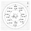
監視地域100は、図2に示すように、建物1の周囲に設定された所定範囲の地域である。図2の例では、監視地域100は、建物1を中心とする同心円上に位置する複数の観測地点を含むように、建物1を中心とする略円形状の範囲に設定されている。分散計測器M1,M2,M3…は、これら複数の観測点に分散して配置されている。図2では、建物1から第1の距離に設定された8箇所の観測地点に分散計測器M1〜M8が配置され、建物1から第2の距離(>第1の距離)にある8箇所の観測地点に分散計測器M9〜M16が配置されている。なお、一例として第1の距離は2km、第2の距離は4kmと仮定する。 As shown in FIG. 2, the
さらに図2の例では、分散計測器M1〜M16は建物1を中心として北、北東、東、南東、南、南西、西、北西の8つの方向に等角度間隔で配置されている。ここでは、分散計測器M1および分散計測器M9は建物1の北、分散計測器M2および分散計測器M10は建物1の北東、分散計測器M3および分散計測器M11は建物1の東、分散計測器M4および分散計測器M12は建物1の南東にそれぞれ配置されている。同様に、分散計測器M5および分散計測器M13は建物1の南、分散計測器M6および分散計測器M14は建物1の南西、分散計測器M7および分散計測器M15は建物1の西、分散計測器M8および分散計測器M16は建物1の北西にそれぞれ配置されている。 Further, in the example of FIG. 2, the dispersion measuring instruments M1 to M16 are arranged at equiangular intervals in eight directions of north, northeast, east, southeast, south, southwest, west, and northwest with the
計測器群5は、このように分散計測器M1〜M16が建物1の周囲に設定された監視地域100に分散して配置されることにより、これら複数台の分散計測器M1〜M16の計測結果から、監視地域100における空気質の分布状況を監視することができる。複数台の分散計測器M1〜M16の計測結果は管理装置91で一元管理されているので、管理装置91は、監視地域100の空気質の分布状況を監視できることになる。 In the
また、各観測地点に空気質に関連した情報を検出するセンサ装置が既に設置されている場合には、分散計測器M1〜M16は、これら既設のセンサ装置を利用してもよい。あるいは、各観測地点に建物が存在する場合には、分散計測器M1〜M16は、各建物に設けられている個別計測器3の室外センサ32を利用してもよい。各建物の個別計測器は制御装置4を介してインターネット8に接続されているので、個別計測器3を分散計測器M1〜M16に利用する場合でも、管理装置91は、複数台の分散計測器M1〜M16の計測結果を一元管理できる。 Moreover, when the sensor apparatus which detects the information relevant to air quality is already installed in each observation point, the dispersion | distribution measuring devices M1-M16 may utilize these existing sensor apparatuses. Or when a building exists in each observation point, the dispersion | distribution measuring device M1-M16 may utilize the
空調設備(空気清浄機61およびエアコン62)は、換気以外の方法で建物1内の空気の温度、湿度、清浄度、気流などを調節し、建物1内を快適な状態に保つ装置である。空調装置は、空気清浄機61およびエアコン62の他、たとえば床暖房等の冷暖房機器、除湿器、加湿器、サーキュレータ等であってもよい。ただし、ここでいう空調装置は、稼動時に電力やガス等のエネルギーを消費する装置のみを含み、稼動時に何らエネルギーを消費しない装置を含まない。また、空調設備は換気設備2に比べると消費電力が大きい。 The air conditioning equipment (the air purifier 61 and the air conditioner 62) is a device that adjusts the temperature, humidity, cleanliness, airflow, and the like of the air in the
空調設備は、制御装置4との通信機能を有しており、制御装置4から送信される制御信号に従って少なくとも稼動・停止の切り替えを行うように構成されている。さらに、空調設備は、制御装置4からの制御信号に従って、運転風量(強・弱)や設定温度を決定する機能も有している。 The air conditioning equipment has a communication function with the
制御装置4は、図1に示すように、各種の処理を行う処理部41と、第1通信インタフェース(以下、「インタフェース」を「I/F」と表記する)42と、第2通信I/F43と、記憶部44と、時計部45とを有している。本実施形態では、制御装置4は、コンピュータを主構成とし、記憶部44に格納されたプログラムを実行することにより、各部の機能を実現する。なお、制御装置4は、上記のプログラムを記録媒体から読み込むか、あるいはインターネット8を介してセンタサーバ(図示せず)からダウンロードすることによってインストールする。 As shown in FIG. 1, the
第1通信I/F42は、建物1に設けられている種々の機器、設備との間で通信する機能を有している。ここでは、第1通信I/F42は、換気設備2、空調設備(空気清浄機61およびエアコン62)、ユーザ端末71、個別計測器3の各々との間で双方向に通信する。本実施形態では、第1通信I/F42は電波を伝送媒体とする無線通信により換気設備2等と通信するが、制御装置(第1通信I/F42)4と換気設備2等との間の通信は無線通信に限らず有線通信であってもよい。 The first communication I /
第2通信I/F43は、インターネット8上の管理装置91やサーバ92との間で双方向に通信する機能を有している。第2通信I/F43は、ルータ75を介してインターネット8に接続されており、Ethernet(登録商標)に準拠した通信を行う。さらに、第2通信I/F43は、ネットワーク機器73,74との通信機能も有している。 The second communication I /
記憶部44は、各分散計測器M1〜M16が配置されている観測地点の位置情報(建物1からの距離および方角)を含む各種のデータを記憶する。観測地点の位置情報は緯度、経度で表されていてもよい。さらに、本実施形態では、記憶部44は、複数台の分散計測器M1〜M16の計測結果の履歴を含むデータを記憶する。 The memory |
時計部45は、現在時刻を計時する。本実施形態では、時計部45はカレンダー機能を有しており、日付、現在時刻を計時する。 The
処理部41は、換気設備2を制御する換気制御部412を有している。ここでは、第1通信I/F42が換気設備2との通信機能を有するので、換気制御部412は、第1通信I/F42から換気設備2へ制御信号を送信することによって、換気設備2を制御する。さらに、換気制御部412は、換気設備2の動作状態(稼動・停止の別、換気風量等)を示す監視信号を第1通信I/F42にて換気設備2から受信することによって、換気設備2の動作状態を監視する。 The
換気制御部412は、その基本的な動作として、建物1内の空気質より建物1外の空気質の方が良好である場合に換気設備2を稼動させるように、個別計測器3の計測結果に基づいて換気設備2を制御する。反対に、建物1外の空気質より建物1外の空気質の方が良好である場合には、換気制御部412は、換気設備2を停止させるように、個別計測器3の計測結果に基づいて換気設備2を制御する。ここでは、第1通信I/F42が個別計測器3との通信機能を有するので、換気制御部412は、個別計測器3の計測結果を第1通信I/F42にて取得し、取得した計測結果に基づいて換気設備2を制御する。 As a basic operation of the
具体例として、建物1の内と外とで気温および湿度が同値(気温22℃、湿度45%)であり、VOC濃度が建物1内で2.2mg/m3、建物1外で1.0mg/m3である場合、換気制御部412は、換気設備2を稼動させて建物1の換気を行う。このとき、換気システム10は、空調設備に比べて消費電力が小さい換気設備2を用いて建物1内の空気質を改善するので、空調設備を用いる場合に比べて省エネルギーになる。その後、建物1の内と外とでVOC濃度が同等になると、換気制御部412は、換気設備2を停止させる。As a specific example, the temperature and humidity are the same inside and outside the building 1 (temperature 22 ° C.,
また、処理部41は、一群の計測器群5を構成する複数台の分散計測器M1〜M16の計測結果に基づいて、空気質が異常値を示す汚染空気が建物1に到達するか否かを予測する予測部411を有している。ここでは、第2通信I/F43が管理装置91との通信機能を有するので、予測部411は、複数台の分散計測器M1〜M16の計測結果を第2通信I/F43にて管理装置91から取得し、取得した計測結果に基づいて汚染空気が建物1に到達するか否かを予測する。 Further, the
たとえば、監視地域100外で発生した汚染空気が建物1に向かっている場合、計測器群5は、まず遠距離側(外側)の(建物1から第2の距離にある)分散計測器M9〜M16のいずれかで計測される空気質が異常値を示すことになる。その後、計測器群5は、最初に汚染空気を検出した分散計測器M9〜M16と建物1との間に位置する近距離側(内側)の(建物1から第1の距離にある)分散計測器M1〜M8で計測される空気質が異常値を示すことになる。つまり、汚染空気が建物1に向かっていれば、建物1から見て同じ方角に位置する外側の分散計測器M0と内側の分散計測器M0とは、順に異常値を計測することになる。 For example, when the polluted air generated outside the
そこで、予測部411は、このように建物1から見て同じ方角に位置する外側の分散計測器M0と内側の分散計測器M0とが順に異常値を計測した場合には、汚染空気が建物1に到達すると予測する。 Therefore, when the outer dispersion measuring instrument M0 and the inner dispersion measuring instrument M0 located in the same direction as viewed from the
換気制御部412は、個別計測器3の計測結果に基づいて換気設備2を制御する機能に加え、予測部411での予測結果に基づいて換気設備2を制御する機能も有している。換気制御部412は、予測部411で汚染空気が建物1に到達すると予測された場合、個別計測器3の計測結果にかかわらず換気設備2を停止させる。つまり、換気制御部412は、個別計測器3の計測結果よりも予測部411の予測結果を優先し、汚染空気の到達が予測部411で予測された場合には、換気設備2を停止させるように換気設備2を制御する。 The
さらに、本実施形態では、処理部41は空調設備を制御する空調制御部413を有している。ここでは、第1通信I/F42が空調設備(空気清浄機61およびエアコン62)との通信機能を有するので、空調制御部413は、第1通信I/F42から空調設備へ制御信号を送信することによって、空調設備を制御する。さらに、空調制御部413は、空調設備の動作状態(稼動・停止の別、運転風量等)を示す監視信号を第1通信I/F42にて空調設備から受信することによって、空調設備の動作状態を監視する。 Furthermore, in this embodiment, the
空調制御部413は、少なくとも換気設備2を停止させる期間には空調設備を稼動させるように構成されている。すなわち、個別計測器3の計測結果において建物1外の空気質より建物1外の空気質の方が良好である場合、および予測部411で汚染空気が建物1に到達すると予測された場合には、空調制御部413は、空調設備を稼動させるように制御する。これにより、換気システム10は、汚染空気が建物1に到達する前に、換気設備2を停止し、空調設備による空気質の改善に切り替えることができる。なお、空調制御部413は、空気清浄機61を稼動させる際、エアコン62を送風モードで稼動させることにより建物1内の空気を循環させ、空気清浄機61による空気質の改善効率を向上させてもよい。 The air
本実施形態では、予測部411は、汚染空気の到達が予測される場合、汚染空気が建物1に到達するタイミングを予測する機能をさらに有しており、制御装置4は、予測部411で予測されたタイミングに合わせて換気設備2を停止させるように構成されている。つまり、予測部411は、汚染空気が建物1に到達すると予測した場合には、建物1に汚染空気が到達するタイミング(以下、「到達タイミング」という)についても予測する。 In the present embodiment, the
すなわち、予測部411は、上述したように建物1から見て同じ方角に位置する外側の分散計測器M0と内側の分散計測器M0とが順に異常値を計測した場合に、この汚染空気の到達タイミングを予測する。この場合、予測部411は、たとえば外側の分散計測器M0が異常値を計測した時刻と、内側の分散計測器M0が異常値を計測した時刻とに基づいて、汚染空気が建物1に到達する時刻(到達タイミング)を予測する。つまり、外側の分散計測器M9が異常値を計測してから、内側の分散計測器M1が異常値を計測するまでに5分掛かった場合、予測部411は、内側の分散計測器M1が異常値を計測したさらに5分後を到達タイミングとして予測する。なお、予測部411は、時刻ではなく、汚染空気が建物1に到達するまでに掛かる時間によって到達タイミングを表してもよい。 That is, the
換気制御部412は、時計部45で計時されている現在時刻が、予測部411で予測された到達タイミングの規定時間前になると、個別計測器3の計測結果にかかわらず換気設備2を停止させる。ここで、規定時間は、予測部411で予測された到達タイミングよりも汚染空気が建物1に早く到達することを見越して設定される時間であって、ユーザによって任意に設定される。つまり、換気制御部412は、予測部411で建物1に汚染空気が到達すると予測された時点ですぐに換気設備2を停止させるのではなく、到達タイミングに合わせて換気設備2を停止させる。 The
また、本実施形態では、処理部41は、観測地点の風向および風速に関する情報を取得する取得部414をさらに有しており、取得部414にて取得した情報を用いて予測部411で予測を行うように構成されている。ここでは、第2通信I/F43がサーバ92との通信機能を有するので、取得部414は、観測地点の風向および風速に関する情報を第2通信I/F43にてサーバ92から取得する。 In the present embodiment, the
記憶部44は、各分散計測器M1〜M16が配置されている観測地点の位置情報(建物1からの距離および方角)を予め記憶しており、予測部411は、この位置情報と、サーバ92から取得した情報とに基づいて空気の移動方向および移動速度を予測できる。したがって、予測部411は、予測される空気の移動方向および移動速度と、複数台の分散計測器M1〜M16の計測結果とに基づいて、汚染空気が建物1に到達するか否かを予測する。さらに、予測部411は、汚染空気が建物1に到達すると予測した場合には、予測される空気の移動方向および移動速度と、複数台の分散計測器M1〜M16の計測結果とに基づいて、到達タイミングを予測する。 The
予測部411は、このように観測地点の位置情報と風向および風速に関する情報とに基づいて予測を行う場合、汚染空気が内側の(建物1から第1の距離にある)分散計測器M1〜M8に到達するタイミングについても予測可能である。つまり、予測部411は、外側の(建物1から第2の距離にある)分散計測器M9〜M16が異常値を計測すると、汚染空気が建物1に到達するタイミング(到達タイミング)だけでなく、汚染空気が内側の分散計測器M1〜M8に到達するタイミングも予測できる。 When the
さらにまた、本実施形態では、制御装置4は、記憶部44に記憶された複数台の分散計測器M1〜M16の計測結果の履歴から汚染空気の拡散パターンを学習して予測部411での予測に用いるように構成されている。具体的には、記憶部44は、複数台の分散計測器M1〜M16の計測結果の履歴を、計測時における日付(あるいは季節)、現在時刻、各種の環境条件(温度、湿度、風向、風速)と対応付けて、一定期間(たとえば1ヵ月)分記憶している。汚染空気の拡散パターンは一意には決まらず、たとえば監視地域の地形や天候などによって大きく変わることがあるので、制御装置4は、過去の履歴から学習した汚染空気の拡散パターンを予測部411の予測に用いることにより、予測精度が向上する。 Furthermore, in the present embodiment, the
また、本実施形態では、制御装置4は、予測部411で汚染空気の到達が予測されてから所定時間の経過後に、個別計測器3で建物1内の空気質より建物1外の空気質の方が良好との計測結果が得られた場合、換気設備2を再稼動させるように構成されている。すなわち、制御装置4は、予測部411で汚染空気の到達が予測されると、換気設備2を一旦停止させるが、所定時間(たとえば5分)が経過しても、汚染空気が建物1に到達しない場合には、換気制御部412にて換気設備2を再稼動させる。 Further, in the present embodiment, the
本実施形態においては、制御装置4は、さらに到着予測部415としての機能を処理部41に有しているが、到着予測部415については後述する。 In the present embodiment, the
次に、本実施形態の換気システム10の動作について図3を参照して説明する。ここでは、建物1内の空気質より建物1外の空気質の方が良好であり、制御装置4が、個別計測器3の計測結果に基づいて換気設備2を稼動させている場合を前提として説明する。また、制御装置4は、個別計測器3および分散計測器M1〜M16の計測結果を定期的(たとえば1分毎)に監視(確認)していると仮定する。 Next, operation | movement of the
この場合において、外側の(建物1から第2の距離にある)分散計測器M9〜M16のいずれかが異常値を計測すると(S1:Yes)、制御装置4は、まずサーバ92から風向および風速に関する情報を取得する(S2)。ここでは、建物1の北西に位置する分散計測器M16が異常値を計測し、そのときの風向が「北西」、風速が「10m/s」であったと仮定する。 In this case, when any of the dispersion measuring instruments M9 to M16 on the outer side (at the second distance from the building 1) measures an abnormal value (S1: Yes), the
制御装置4は、分散計測器M1〜M16の計測結果および処理S2で取得した情報に基づいて、汚染空気が建物1に到達するか否かを予測する(S3)。制御装置4は、汚染空気が建物1に到達すると予測した場合(S3:Yes)、その汚染空気の到達タイミングを予測する(S4)。処理S4において、予測部411は、汚染空気が建物1に到達するタイミングだけでなく、分散計測器M16と建物1との間(つまり建物1から第1の距離であって北西)に位置する分散計測器M8に汚染空気が到達するタイミングについても予測する。 The
ここでは一例として、分散計測器M16から分散計測器M8までの距離は2km、風速が10m/sであるから、予測部411は、汚染空気が分散計測器M8に到達するタイミングを、分散計測器M16が異常値を計測してから200s後と予測する。同様に、分散計測器M16から建物1までの距離は4km、風速が10m/sであるから、予測部411は、汚染空気が建物1に到達するタイミングを、分散計測器M16が異常値を計測してから400s後と予測する。 Here, as an example, since the distance from the dispersion measuring instrument M16 to the dispersion measuring instrument M8 is 2 km and the wind speed is 10 m / s, the
その後、制御装置4は、個別計測器3および分散計測器M1〜M16の計測結果を監視する周期を短縮し(たとえば1分毎を10秒毎とし)、空気質の監視を強化する(S5)。このとき、制御装置4は、少なくとも個別計測器3と、汚染空気の到達が予測される分散計測器M8とを対象として監視を強化(監視周期を短縮)すればよく、全ての分散計測器M0について監視を強化する必要はない。また、制御装置4は、汚染空気の拡散(広がり)も考慮する場合、汚染空気の到達が予測される分散計測器M8の周辺の分散計測器M1,M7を、監視を強化する対象に含めてもよい。 Thereafter, the
その後、制御装置4は、内側の(建物1から第1の距離にある)分散計測器M8が異常値を計測すると(S6:Yes)、汚染空気の到達タイミングに合わせて、汚染空気が建物1に到達する前に換気設備2を停止させ(S7)、空調設備を稼動させる(S8)。このとき、制御装置4は、予測部411で予測された汚染空気が分散計測器M8に到達するタイミングと、実際に分散計測器M8が異常値を計測したタイミングとの差に基づいて、予測部411で予測される汚染空気が建物1に到達するタイミングを補正する。 Thereafter, when the dispersion measuring instrument M8 on the inner side (at the first distance from the building 1) measures an abnormal value (S6: Yes), the
なお、制御装置4は、外側の分散計測器M9〜M16で異常値が計測されない場合(S1:No)、あるいは予測部411で汚染空気が建物1に到達しないと予測された場合(S3:No)、S1に戻って処理を実行する。また、制御装置4は、内側の分散計測器M1〜M8で異常値が計測されない場合(S6:No)、S6に戻って処理を実行する。 In addition, when the abnormal value is not measured by the outside dispersion measuring instruments M9 to M16 (S1: No), or the
また、他の動作例として、制御装置4は、外側の分散計測器M9〜M16から建物1までの距離や、風向、風速等によっては、外側の分散計測器M9〜M16のいずれかが異常値を計測した場合、すぐに換気設備2を停止させてもよい。この場合、制御装置4は、汚染空気が建物1に到達するか否かを予測する前に、まず換気設備2を停止させることになる。その際、制御装置4は、個別計測器3および分散計測器M1〜M16の計測結果を監視する周期を短縮し、空気質の監視を強化する。したがって、制御装置4は、外側の分散計測器M9〜M16のいずれかが異常値を計測してから汚染空気が建物1に到達するまでにあまり時間が掛からない場合でも、汚染空気が建物1に到達する前に換気設備2を停止させることができる。 As another example of operation, the
その後、所定時間以内に、内側の分散計測器M1〜M8、あるいは個別計測器3が建物1外の空気質の異常値を計測した場合、制御装置4は、換気設備2を停止させたままとして空調設備を稼動させる。一方、内側の分散計測器M1〜M8と、個別計測器3とのいずれも建物1外の空気質の異常値を計測しないまま所定時間が経過した場合、制御装置4は、換気設備2を再稼動させる。なお、制御装置4は、換気設備2を再稼動させる場合でも、最初に異常値を計測した分散計測器M9〜M16の計測結果が正常値に復帰するまでは、空気質の監視を強化(監視周期を短縮)した状態を継続することが望ましい。 After that, if the inner dispersion measuring instruments M1 to M8 or the
さらに他の動作例として、制御装置4は、外側の分散計測器M9〜M16のいずれかが異常値を計測した後、内側の分散計測器M1〜M8が異常値を計測する前に、個別計測器3が建物1外の空気質の異常値を計測した場合、すぐに換気設備2を停止させてもよい。このとき、制御装置4は、換気設備2を停止させつつ空調設備を稼動させることで、空調設備による空気質の改善に切り替える。したがって、制御装置4は、内側の分散計測器M1〜M8で異常値が計測されなかった場合にも、汚染空気が建物1に到達すればすぐに換気設備2を停止させることができる。 As yet another operation example, the
あるいは、制御装置4は、内側の分散計測器M1〜M8が異常値を計測すると、予測部411で予測される到達タイミングに関わらず、すぐに換気設備2を停止させ、空調設備を稼動させるように構成されていてもよい。この場合、制御装置4は、汚染空気の拡散が予測困難であっても、内側の分散計測器M1〜M8に汚染空気が到達した時点で換気設備2を停止させるので、汚染空気が建物1に到達する前に確実に換気設備2を停止させることができる。 Alternatively, when the inner dispersion measuring instruments M1 to M8 measure abnormal values, the
以上説明した構成の換気システム10によれば、制御装置4は、複数台の分散計測器M0の計測結果に基づいて、空気質が異常値を示す汚染空気が建物1に到達するか否かを予測する予測部411を有している。さらに制御装置4は、予測部411で汚染空気の到達が予測された場合、個別計測器3の計測結果にかかわらず換気設備2を停止させるように構成されている。 According to the
したがって、制御装置4は、建物1周辺に汚損空気が存在するような状況においては、そのことを事前に予測して換気設備2を停止させ、建物1外から建物1内に汚染空気が取り込まれてしまうことを回避できる。要するに、換気システム10は、建物1内の空気質より建物1外の空気質の方が良好である場合には、建物1の換気を行うことにより建物1内の空気質を改善し、換気による建物1内の空気質の改善効果が期待できない場合には換気設備2を停止させる。その結果、換気システム10は、換気設備2にてエネルギー(電力)を無駄に消費することなく、建物1の換気を行うことにより建物1内の空気質を改善できる。 Therefore, in a situation where contaminated air exists around the
また、本実施形態では、換気システム10は、換気設備2とは別に建物1に設けられ建物1内の空気質を改善する空調設備(空気清浄機61およびエアコン62)をさらに備えている。制御装置4は、空調設備を制御する機能(空調制御部413)をさらに有し、少なくとも換気設備2を停止させる期間には空調設備を稼動させるように構成されている。そのため、換気システム10は、換気設備2を停止期間には、空調設備により建物1内の空気質を改善することができ、換気以外の方法で建物1内の快適性を維持できる。 Moreover, in this embodiment, the
さらにまた、本実施形態では、予測部411は、汚染空気の到達が予測される場合、汚染空気が建物1に到達するタイミングを予測する機能をさらに有し、制御装置4は、予測部411で予測されたタイミングに合わせて換気設備2を停止させるように構成される。すなわち、制御装置4は、予測部411で建物1に汚染空気が到達すると予測された時点ですぐに換気設備2を停止させるのではなく、到達タイミングに合わせて換気設備2を停止させるので、換気設備2により建物1内の空気質を改善する期間を長く確保できる。 Furthermore, in this embodiment, when the arrival of the contaminated air is predicted, the
また、本実施形態においては、制御装置4は、観測地点の風向および風速に関する情報を取得する取得部414をさらに有し、取得部414にて取得した情報を用いて予測部411で予測を行うように構成されている。したがって、制御装置4は、予測部411での予測の精度が向上するという利点がある。 Moreover, in this embodiment, the
さらに、本実施形態では、制御装置4は、複数台の分散計測器M1〜M16の計測結果の履歴を記憶する記憶部44をさらに有し、記憶部44に記憶された履歴から汚染空気の拡散パターンを学習して予測部411での予測に用いるように構成されている。したがって、制御装置4は、予測部411での予測の精度が向上するという利点がある。 Further, in the present embodiment, the
さらにまた、本実施形態では、制御装置4は、予測部411で汚染空気の到達が予測されてから所定時間の経過後に、個別計測器3で建物1内の空気質より建物1外の空気質の方が良好との計測結果が得られた場合、換気設備2を再稼動させる。そのため、制御装置4は、汚染空気の到達が予測されたものの実際には汚染空気が建物1に到達しない場合には、換気設備2を再稼動させるので、換気設備2により建物1内の空気質を改善する期間を長く確保できる。 Furthermore, in the present embodiment, the
なお、本実施形態では、分散計測器M1〜M16の計測結果は、管理装置91で一元管理されているが、この構成に限らず、制御装置4で管理されていてもよい。また、制御装置4は、その機能の一部が他装置に設けられていてもよく、たとえば予測部411の機能が管理装置91に設けられていてもよい。この場合、制御装置は、複数の装置(たとえば制御装置4と管理装置91)からなり、汚染空気が建物1に到達するか否かについては管理装置91で予測し、その予測結果に基づいて制御装置4で換気設備2を制御することになる。 In the present embodiment, the measurement results of the dispersion measuring instruments M <b> 1 to M <b> 16 are centrally managed by the management device 91, but not limited to this configuration, the measurement results may be managed by the
ところで、本実施形態の換気システム10では、制御装置4は、人が建物1へ到着するタイミングを予測する到着予測部415をさらに有し、到着予測部415で予測されるタイミングに合わせて建物1内の空気質を改善するように構成されている。 By the way, in the
具体的には、到着予測部415は、GPS(Global Positioning System)機能を有するユーザ端末71の現在位置や位置変化などの情報を利用して、外出中のユーザ(家人)が建物1に到着(帰宅)する時刻を人が建物1に到着するタイミングとして予測する。制御装置4は、ユーザ端末71の現在位置等の情報をインターネット8経由で随時取得可能である。つまり、ユーザは外出時にユーザ端末71を携帯しているだけで、制御装置4において、人が建物1に到着するタイミング(以下、「帰宅タイミング」という)を予測できる。なお、到着予測部415は、時刻ではなく、人が建物1に到着するまでに掛かる時間によって帰宅タイミングを表してもよい。 Specifically, the
換気設備2や空調設備は、稼動して建物1内の空気質をすぐに改善できるのではなく、空気質を改善するのにある程度の時間を要する。そこで、制御装置4は、到着予測部415で予測された帰宅タイミングに合わせて建物1内の空気質が改善されるように、予測された帰宅タイミングに基づいて換気設備2や空調設備(空気清浄機61およびエアコン62)を制御する。 The
制御装置4は、たとえばユーザが外出して建物1が無人になると換気設備2および空調設備を停止させ、且つ到着予測部415で予測された帰宅タイミングには建物1内の空気質が正常値となるように、帰宅タイミングに合わせて換気設備2や空調設備を制御する。これにより、換気システム10は、建物1が無人の期間に換気設備2および空調設備による無駄な電力消費を抑えつつ、ユーザが建物1に到着(帰宅)するタイミングに合わせて建物1内の空気質を改善できる。 For example, when the user goes out and the
ここでは、制御装置4は、到着予測部415で予測される帰宅タイミングと建物1内の空気質の改善に要する時間とから、建物1内の空気質の改善の開始タイミングを逆算するように構成されている。そのため、換気システム10は、ユーザが建物1に到着(帰宅)する頃には建物1内の空気質の改善を完了することができる。 Here, the
また、制御装置4は、人が移動に要する時間や建物1内の空気質の改善に要する時間を学習し、到着予測部415での帰宅タイミングの予測や換気設備2および空調設備の制御に用いるように構成されている。 In addition, the
たとえば、制御装置4は、所定の場所(たとえば駅)から建物1までの移動に要する時間を都度計測して、その平均値を求めることで所定の場所から建物1までの移動に要する時間を学習し、帰宅タイミングを予測する。また、制御装置4は、GPSを利用してユーザの移動経路を識別して経路ごとに建物1までの移動に要する時間を学習し、ユーザが通っている経路に基づいて帰宅タイミングを予測する。ユーザ端末71が歩数計の機能を有する場合には、制御装置4は、ユーザが所定の場所(たとえば駅)から建物1まで移動するのに要する総歩数を学習し、現在の歩数から帰宅タイミングを予測する。また、制御装置4は、建物1外の温度や湿度ごとに、所定時間内に調節可能な温度や湿度の最大変化量を学習し、建物1内を所定の温度、湿度に調節するのに要する時間を判断する。 For example, the
なお、本実施形態では、図1に示す換気システム10を例に説明したが、この換気システム10は本発明の一態様に過ぎず、適宜の変更が可能である。すなわち、換気システム10は、少なくとも制御装置4が、複数台の分散計測器M0の計測結果に基づいて汚染空気が建物1に到達するか否かを予測する予測部411を有し、汚染空気の到達が予測された場合換気設備2を停止させる構成であればよい。 In the present embodiment, the
たとえば、空調設備は適宜省略可能であり、また、制御装置4においては空調制御部413、取得部414、到着予測部415等はそれぞれ適宜省略可能である。さらに、制御装置4は、予測部411で汚染空気が建物1に到達するタイミングを予測する機能や、記憶部44に記憶された履歴から汚染空気の拡散パターンを学習する機能についても適宜省略可能である。また、制御装置4は、予測部411で汚染空気の到達が予測されてから所定時間の経過後に、個別計測器3で建物1内の空気質より建物1外の空気質の方が良好との計測結果が得られた場合に換気設備2を再稼動させる機能についても適宜省略可能である。 For example, the air conditioning equipment can be omitted as appropriate, and in the
(実施形態2)
本実施形態の換気システムは、高層マンション(集合住宅)のように複数の階層を有する建物に適用される点で実施形態1の換気システムとは相違する。以下、実施形態1と同様の構成については共通の符号を付して適宜説明を省略する。(Embodiment 2)
The ventilation system according to the present embodiment is different from the ventilation system according to the first embodiment in that the ventilation system is applied to a building having a plurality of floors such as a high-rise apartment (an apartment house). Hereinafter, the same configurations as those of the first embodiment are denoted by common reference numerals, and description thereof will be omitted as appropriate.
本実施形態では、制御装置4は、階層ごとに換気設備2を制御し、予測部411で汚染空気の到達が予測された場合、汚染空気の到達が早い階層から順に換気設備2を停止させるように構成されている。 In the present embodiment, the
すなわち、風向、風速は地上高によって大きく異なるため、高層マンションなどの建物1においては、たとえば風向は同じでも地上高が大きい上層階ほど風速が速く、汚染空気の到達タイミングが上層階ほど早くなる場合がある。このような場合、制御装置4は、汚染空気の到達が早い階層、つまり高層階から順に換気設備2を停止させる。また、地形や近隣の建物との関係によっては、高層マンションなどの建物1において、汚染空気の到達タイミングが低層階や中層階ほど早くなる場合もある。このような場合、制御装置4は、汚染空気の到達が早い階層、つまり低層階や中層階から順に換気設備2を停止させる。 That is, since the wind direction and the wind speed vary greatly depending on the ground height, in a
したがって、制御装置4は、汚染空気の到達が早い階層については汚染空気が到達する前に確実に換気設備2を停止させることができ、汚染空気の到達が遅い階層については換気設備2により建物1内の空気質を改善する期間を長く確保できる。 Therefore, the
ここで、制御装置4は、階層ごとの汚染空気が到達する順番を、統計的に求めてもよいし、現在の風向、風速等から求めてもよい。たとえば、個別計測器3が階層ごとに設けられている場合には、制御装置4は、これら複数台の個別計測器3の計測結果の履歴から汚染空気の到達順を統計的に求めることができる。また、建物1の周囲の風向、風速等が複数の地上高について計測されている場合には、制御装置4は、これらの現在の計測結果から汚染空気の到達順を求めることが可能である。 Here, the
なお、集合住宅のような建物1においては、制御装置4は建物1全体で1台設けられていてもよいし、階層ごとに1台ずつ設けられていてもよいし、各住戸ごとに1台ずつ設けられていてもよい。 In the
その他の構成および機能は実施形態1と同様である。 Other configurations and functions are the same as those of the first embodiment.
1 建物
2 換気設備
3 個別計測器
4 制御装置
44 記憶部
61 空気清浄機(空調設備)
62 エアコン(空調設備)
100 監視地域
411 予測部
414 取得部
415 到着予測部
M0,M1,M2,M3… 分散計測器DESCRIPTION OF
62 Air conditioner
100
Claims (10)
Translated fromJapanese前記建物の内および外の空気質を計測する個別計測器と、
前記個別計測器の計測結果に基づいて前記換気設備を制御し、前記建物内の空気質より当該建物外の空気質の方が良好である場合に前記換気設備を稼動させる制御装置と、
前記建物の周囲に設定された監視地域内の複数の観測地点に分散して配置され各観測地点の空気質を計測する複数台の分散計測器とを備え、
前記制御装置は、
前記複数台の前記分散計測器の計測結果に基づいて、空気質が異常値を示す汚染空気が前記建物に到達するか否かを予測する予測部を有し、
前記予測部で前記汚染空気の到達が予測された場合、前記個別計測器の計測結果にかかわらず前記換気設備を停止させるように構成されている
ことを特徴とする換気システム。Ventilation equipment for ventilation of the building,
An individual measuring instrument for measuring the air quality inside and outside the building;
Controlling the ventilation equipment based on the measurement result of the individual measuring instrument, and a control device for operating the ventilation equipment when the air quality outside the building is better than the air quality inside the building,
A plurality of distributed measuring devices that are distributed and arranged at a plurality of observation points in a monitoring area set around the building and measure the air quality at each observation point;
The controller is
Based on the measurement results of the plurality of the dispersion measuring instruments, a prediction unit that predicts whether or not contaminated air whose air quality shows an abnormal value reaches the building,
When the prediction unit predicts the arrival of the contaminated air, the ventilation system is configured to stop the ventilation equipment regardless of the measurement result of the individual measuring device.
前記制御装置は、前記空調設備を制御する機能をさらに有し、少なくとも前記換気設備を停止させる期間には前記空調設備を稼動させるように構成されている
ことを特徴とする請求項1に記載の換気システム。In addition to the ventilation facility, the building is further provided with an air conditioning facility provided in the building for improving air quality in the building,
2. The control device according to claim 1, further comprising a function of controlling the air conditioning equipment, and configured to operate the air conditioning equipment at least during a period in which the ventilation equipment is stopped. Ventilation system.
前記制御装置は、前記予測部で予測されたタイミングに合わせて前記換気設備を停止させるように構成されている
ことを特徴とする請求項1または2に記載の換気システム。The prediction unit further has a function of predicting the timing when the contaminated air reaches the building when the arrival of the contaminated air is predicted,
The ventilation system according to claim 1 or 2, wherein the control device is configured to stop the ventilation facility in accordance with the timing predicted by the prediction unit.
前記観測地点の風向および風速に関する情報を取得する取得部をさらに有し、
当該取得部にて取得した情報を用いて前記予測部で予測を行うように構成されている
ことを特徴とする請求項1〜3のいずれか1項に記載の換気システム。The controller is
It further has an acquisition unit that acquires information on the wind direction and wind speed of the observation point,
The ventilation system according to any one of claims 1 to 3, wherein the prediction unit is configured to perform prediction using information acquired by the acquisition unit.
ことを特徴とする請求項1〜4のいずれか1項に記載の換気システム。The control device measures that the air quality outside the building is better than the air quality inside the building with the individual measuring device after a predetermined time has elapsed since the arrival of the contaminated air is predicted by the prediction unit. The ventilation system according to any one of claims 1 to 4, wherein when the result is obtained, the ventilation system is configured to be restarted.
前記制御装置は、階層ごとに前記換気設備を制御し、前記予測部で前記汚染空気の到達が予測された場合、前記汚染空気の到達が早い階層から順に前記換気設備を停止させるように構成されている
ことを特徴とする請求項1〜5のいずれか1項に記載の換気システム。The building has a plurality of levels,
The control device is configured to control the ventilation equipment for each level, and when the prediction unit predicts arrival of the contaminated air, the control unit is configured to stop the ventilation equipment in order from the level of arrival of the contaminated air. The ventilation system according to any one of claims 1 to 5, wherein the ventilation system is provided.
前記複数台の前記分散計測器の計測結果の履歴を記憶する記憶部をさらに有し、
前記記憶部に記憶された履歴から前記汚染空気の拡散パターンを学習して前記予測部での予測に用いるように構成されている
ことを特徴とする請求項1〜6のいずれか1項に記載の換気システム。The controller is
A storage unit for storing a history of measurement results of the plurality of dispersion measuring instruments;
It is comprised so that the diffusion pattern of the contaminated air may be learned from the history memorize | stored in the said memory | storage part, and it may be used for the prediction in the said prediction part. The any one of Claims 1-6 characterized by the above-mentioned. Ventilation system.
人が前記建物へ到着するタイミングを予測する到着予測部をさらに有し、
前記到着予測部で予測されるタイミングに合わせて前記建物内の空気質を改善するように構成されている
ことを特徴とする請求項1〜7のいずれか1項に記載の換気システム。The controller is
An arrival prediction unit for predicting the timing when a person arrives at the building;
It is comprised so that the air quality in the said building may be improved according to the timing estimated in the said arrival prediction part. The ventilation system of any one of Claims 1-7 characterized by the above-mentioned.
前記到着予測部で予測されるタイミングと前記建物内の空気質の改善に要する時間とから、当該建物内の空気質の改善の開始タイミングを逆算するように構成されている
ことを特徴とする請求項8に記載の換気システム。The controller is
The start timing for improving the air quality in the building is calculated backward from the timing predicted by the arrival prediction unit and the time required for improving the air quality in the building. Item 9. The ventilation system according to item 8.
前記建物の周囲に設定された監視地域内の複数の観測地点に分散して配置され各観測地点の空気質を計測する複数台の分散計測器の計測結果に基づいて、空気質が異常値を示す汚染空気が前記建物に到達するか否かを予測する予測部を有し、
前記予測部で前記汚染空気の到達が予測された場合、前記個別計測器の計測結果にかかわらず前記換気設備を停止させるように構成されている
ことを特徴とする制御装置。Based on the measurement results of individual measuring instruments that measure the air quality inside and outside the building, the ventilation equipment that ventilates the building is controlled, and the air quality outside the building is better than the air quality inside the building A control device for operating the ventilation equipment when
Based on the measurement results of a plurality of distributed measuring instruments that are distributed at a plurality of observation points in the monitoring area set around the building and measure the air quality at each observation point, the air quality has an abnormal value. A predicting unit for predicting whether or not contaminated air to reach the building;
When the prediction unit predicts the arrival of the contaminated air, the control device is configured to stop the ventilation equipment regardless of the measurement result of the individual measuring device.
Priority Applications (3)
| Application Number | Priority Date | Filing Date | Title |
|---|---|---|---|
| JP2013101203AJP2014222116A (en) | 2013-05-13 | 2013-05-13 | Ventilation system and control device |
| PCT/JP2014/002278WO2014185013A1 (en) | 2013-05-13 | 2014-04-23 | Ventilation system, and control device |
| CN201480027677.2ACN105229389B (en) | 2013-05-13 | 2014-04-23 | Ventilation system and controls |
Applications Claiming Priority (1)
| Application Number | Priority Date | Filing Date | Title |
|---|---|---|---|
| JP2013101203AJP2014222116A (en) | 2013-05-13 | 2013-05-13 | Ventilation system and control device |
Publications (1)
| Publication Number | Publication Date |
|---|---|
| JP2014222116Atrue JP2014222116A (en) | 2014-11-27 |
Family
ID=51898006
Family Applications (1)
| Application Number | Title | Priority Date | Filing Date |
|---|---|---|---|
| JP2013101203AWithdrawnJP2014222116A (en) | 2013-05-13 | 2013-05-13 | Ventilation system and control device |
Country Status (3)
| Country | Link |
|---|---|
| JP (1) | JP2014222116A (en) |
| CN (1) | CN105229389B (en) |
| WO (1) | WO2014185013A1 (en) |
Cited By (9)
| Publication number | Priority date | Publication date | Assignee | Title |
|---|---|---|---|---|
| JP2018501459A (en)* | 2014-12-24 | 2018-01-18 | コーニンクレッカ フィリップス エヌ ヴェKoninklijke Philips N.V. | Configuration and method for room air management |
| JP2018044751A (en)* | 2016-09-16 | 2018-03-22 | 日立アプライアンス株式会社 | Electric device control system |
| JP2018162925A (en)* | 2017-03-27 | 2018-10-18 | 三菱電機株式会社 | Air conditioning control device, air conditioner, air conditioning system, air conditioning control method and program |
| JP2018179476A (en)* | 2017-04-21 | 2018-11-15 | 住友重機械工業株式会社 | Air purification system |
| JP2020118420A (en)* | 2019-01-28 | 2020-08-06 | 富士工業株式会社 | Ventilation system |
| KR20200098663A (en)* | 2018-02-27 | 2020-08-20 | 파나소닉 아이피 매니지먼트 가부시키가이샤 | Air pollution display terminal |
| JP2021517233A (en)* | 2018-03-09 | 2021-07-15 | レマ ヤピ ヴェ ミマーリック アノニム シルケティ | Smart ventilation system |
| WO2021149179A1 (en)* | 2020-01-22 | 2021-07-29 | 三菱電機株式会社 | Ventilation system and ventilation management device |
| JP2023053709A (en)* | 2021-10-01 | 2023-04-13 | 株式会社フジタ | ventilation system |
Families Citing this family (14)
| Publication number | Priority date | Publication date | Assignee | Title |
|---|---|---|---|---|
| GB2588863B (en)* | 2016-04-24 | 2021-10-27 | David Mervin Jones | Heating and ventilation system |
| CN106369751A (en)* | 2016-09-12 | 2017-02-01 | 青岛海尔空调器有限总公司 | Fresh air exchange control method |
| EP3521715B1 (en)* | 2016-09-29 | 2021-08-25 | Mitsubishi Electric Corporation | Ventilation system |
| GB2563008B (en)* | 2017-05-24 | 2020-04-08 | Future Decisions Ltd | Air pollution management system and method of controlling a ventilation system |
| CN109595754A (en)* | 2017-09-29 | 2019-04-09 | 李在燮 | Indoor air quality based on Internet of Things improves system |
| KR102472214B1 (en) | 2018-02-28 | 2022-11-30 | 삼성전자주식회사 | Compound control apparatus and method thereof in air conditioning system |
| TWI679378B (en)* | 2018-08-22 | 2019-12-11 | 崑山科技大學 | Air quality micro-monitoring system and air quality purification method |
| CN111174332B (en)* | 2018-10-24 | 2021-05-25 | 青岛海尔空调器有限总公司 | Control method and device for portable air conditioner |
| TWI690681B (en)* | 2019-01-02 | 2020-04-11 | 逢甲大學 | Control system of air quality and the operating method thereof |
| SG11202111332TA (en)* | 2019-04-22 | 2021-11-29 | Panasonic Ip Man Co Ltd | Air conditioning system |
| TWI695958B (en)* | 2019-10-16 | 2020-06-11 | 國立高雄大學 | Air quality monitoring system |
| CN113781693B (en)* | 2020-06-28 | 2023-05-23 | 江苏人加信息科技有限公司 | Block chain identity information authentication system based on big data |
| TWI839611B (en)* | 2021-04-29 | 2024-04-21 | 研能科技股份有限公司 | Indoor air pollution prevention system |
| TWI834971B (en) | 2021-05-14 | 2024-03-11 | 研能科技股份有限公司 | Indoor air pollution prevention system |
Family Cites Families (7)
| Publication number | Priority date | Publication date | Assignee | Title |
|---|---|---|---|---|
| CN1727783A (en)* | 2004-07-26 | 2006-02-01 | 乐金电子(天津)电器有限公司 | Device for controlling indoor air quality through using ventilation system, and method |
| JP2006133121A (en)* | 2004-11-08 | 2006-05-25 | Daikin Ind Ltd | Base, air pollution information providing system, air pollution prediction method, and ventilation device |
| FR2887632B1 (en)* | 2005-06-22 | 2007-10-05 | Valeo Systemes Thermiques | DEVICE AND METHOD FOR MONITORING AND CONTROLLING AIR QUALITY, FOR MOTOR VEHICLE |
| ES2605941T3 (en)* | 2006-02-21 | 2017-03-17 | Urecsys - Urban Ecology Systems - Indoor Air Quality Management Ltd. | System and method to evaluate and reduce air pollution by regulating airflow ventilation |
| JP2009192199A (en)* | 2008-02-18 | 2009-08-27 | Toyota Motor Corp | Ventilation system and building with the same |
| JP5072784B2 (en)* | 2008-09-11 | 2012-11-14 | 株式会社東芝 | Room pressure control device and room pressure control method |
| CN102121740A (en)* | 2010-01-12 | 2011-07-13 | 珠海格力电器股份有限公司 | Air conditioner control system and control method and air conditioner |
- 2013
- 2013-05-13JPJP2013101203Apatent/JP2014222116A/ennot_activeWithdrawn
- 2014
- 2014-04-23WOPCT/JP2014/002278patent/WO2014185013A1/enactiveApplication Filing
- 2014-04-23CNCN201480027677.2Apatent/CN105229389B/enactiveActive
Cited By (15)
| Publication number | Priority date | Publication date | Assignee | Title |
|---|---|---|---|---|
| JP2018501459A (en)* | 2014-12-24 | 2018-01-18 | コーニンクレッカ フィリップス エヌ ヴェKoninklijke Philips N.V. | Configuration and method for room air management |
| RU2679989C2 (en)* | 2014-12-24 | 2019-02-14 | Конинклейке Филипс Н.В. | Device and method foe controlling air indoor quality |
| JP2018044751A (en)* | 2016-09-16 | 2018-03-22 | 日立アプライアンス株式会社 | Electric device control system |
| JP2018162925A (en)* | 2017-03-27 | 2018-10-18 | 三菱電機株式会社 | Air conditioning control device, air conditioner, air conditioning system, air conditioning control method and program |
| JP7004508B2 (en) | 2017-03-27 | 2022-01-21 | 三菱電機株式会社 | Air conditioning control device, air conditioner, air conditioning system, air conditioning control method and program |
| JP2018179476A (en)* | 2017-04-21 | 2018-11-15 | 住友重機械工業株式会社 | Air purification system |
| KR20200098663A (en)* | 2018-02-27 | 2020-08-20 | 파나소닉 아이피 매니지먼트 가부시키가이샤 | Air pollution display terminal |
| KR102439917B1 (en)* | 2018-02-27 | 2022-09-02 | 파나소닉 아이피 매니지먼트 가부시키가이샤 | air pollution indicator terminal |
| JP2021517233A (en)* | 2018-03-09 | 2021-07-15 | レマ ヤピ ヴェ ミマーリック アノニム シルケティ | Smart ventilation system |
| JP2020118420A (en)* | 2019-01-28 | 2020-08-06 | 富士工業株式会社 | Ventilation system |
| WO2021149179A1 (en)* | 2020-01-22 | 2021-07-29 | 三菱電機株式会社 | Ventilation system and ventilation management device |
| JPWO2021149179A1 (en)* | 2020-01-22 | 2021-07-29 | ||
| JP7325546B2 (en) | 2020-01-22 | 2023-08-14 | 三菱電機株式会社 | ventilation system |
| JP2023053709A (en)* | 2021-10-01 | 2023-04-13 | 株式会社フジタ | ventilation system |
| JP7709884B2 (en) | 2021-10-01 | 2025-07-17 | 株式会社フジタ | Ventilation system |
Also Published As
| Publication number | Publication date |
|---|---|
| WO2014185013A1 (en) | 2014-11-20 |
| CN105229389B (en) | 2018-11-02 |
| CN105229389A (en) | 2016-01-06 |
Similar Documents
| Publication | Publication Date | Title |
|---|---|---|
| WO2014185013A1 (en) | Ventilation system, and control device | |
| CA2918085C (en) | An hvac system and an hvac controller configured to operate the hvac system based on air pollutant data and user comfort | |
| CN111512094B (en) | Relative humidity control system and method | |
| US12345433B2 (en) | Indoor air quality sensor calibration systems and methods | |
| EP3781878B1 (en) | System and method for adjusting mitigation thresholds | |
| CA2923242C (en) | Air treatment device for hvac systems | |
| US11421901B2 (en) | Coordinated control of standalone and building indoor air quality devices and systems | |
| WO2019204785A1 (en) | Particulate-matter-size-based fan control system | |
| KR102486845B1 (en) | Air purifying system | |
| JP2014142164A (en) | Environmental management device | |
| JP7394641B2 (en) | air conditioning ventilation system | |
| CN105674491A (en) | Cloud platform-based indoor environment management system | |
| JP2016142489A (en) | Air cleaner monitoring device and air cleaner management system | |
| US20200124303A1 (en) | Air conditioning apparatus, control method for same, and control program | |
| KR20140003760A (en) | Control system for air quality | |
| JP7103870B2 (en) | Control system for air purification equipment | |
| KR102479889B1 (en) | Air quality analysis system based on artificial intelligence for indoor air purification control | |
| KR20220064736A (en) | Method And Apparatus for Managing Air Quality by Using Indoor and Outdoor Sensor Module | |
| US20110307099A1 (en) | Device management system | |
| JP2002061930A (en) | Air conditioning system for effecting integrated control of ventilation fan, air conditioner and the like | |
| TWI813745B (en) | Air purifier and method for controlling the air purifier | |
| JP2015114053A (en) | Air conditioning management system and air conditioning management program | |
| EP4417885A1 (en) | Ventilation control system | |
| WO2023211866A1 (en) | Indoor air quality management apparatus and method | |
| HK40040776A (en) | Intelligent apparatus, systems, and methods for providing thermal comfort |
Legal Events
| Date | Code | Title | Description |
|---|---|---|---|
| A711 | Notification of change in applicant | Free format text:JAPANESE INTERMEDIATE CODE: A711 Effective date:20141006 | |
| A621 | Written request for application examination | Free format text:JAPANESE INTERMEDIATE CODE: A621 Effective date:20160112 | |
| A761 | Written withdrawal of application | Free format text:JAPANESE INTERMEDIATE CODE: A761 Effective date:20160215 | |
| A521 | Request for written amendment filed | Free format text:JAPANESE INTERMEDIATE CODE: A523 Effective date:20160307 | |
| A521 | Request for written amendment filed | Free format text:JAPANESE INTERMEDIATE CODE: A821 Effective date:20160307 |