JP2014221615A - Parking assisting device - Google Patents
Parking assisting deviceDownload PDFInfo
- Publication number
- JP2014221615A JP2014221615AJP2013102221AJP2013102221AJP2014221615AJP 2014221615 AJP2014221615 AJP 2014221615AJP 2013102221 AJP2013102221 AJP 2013102221AJP 2013102221 AJP2013102221 AJP 2013102221AJP 2014221615 AJP2014221615 AJP 2014221615A
- Authority
- JP
- Japan
- Prior art keywords
- parking
- low friction
- route
- steering
- region
- Prior art date
- Legal status (The legal status is an assumption and is not a legal conclusion. Google has not performed a legal analysis and makes no representation as to the accuracy of the status listed.)
- Pending
Links
Images


Landscapes
- Steering Control In Accordance With Driving Conditions (AREA)
Abstract
Translated fromJapaneseDescription
Translated fromJapanese本発明は、自車両を駐車位置に駐車させるための駐車支援を行う駐車支援装置に関する。 The present invention relates to a parking assistance apparatus that performs parking assistance for parking a host vehicle at a parking position.
近年、車両を駐車させる場合に運転者に各種支援を行う駐車支援装置が開発されている。例えば、特許文献1には、並列駐車や縦列駐車等の際に、車両を目標駐車位置へ自動的に操舵して駐車操作の支援を行う自動操舵駐車支援装置が開示されている。また、操舵制御を行うための操舵装置として、モータによるEPS[Electric Power Steering](電動パワーステアリング)が増えている。 In recent years, parking assistance devices have been developed that provide various assistance to the driver when the vehicle is parked. For example,
車両を駐車させるときには、据え切り操舵等のEPSに大きな負荷がかかる操舵が求められる。このようなEPSの大きな負荷は、操舵に要する電流量が多くなる。 When the vehicle is parked, steering that requires a large load on EPS such as stationary steering is required. Such a large load of EPS increases the amount of current required for steering.
そこで、本発明は、操舵での負荷を低減できる駐車支援装置を提供することを課題とする。 Then, this invention makes it a subject to provide the parking assistance apparatus which can reduce the load by steering.
本発明に係る駐車支援装置は、自車両を駐車位置に駐車させるための駐車支援を行う駐車支援装置であって、駐車位置を検出する駐車位置検出手段と、駐車位置検出手段で検出した駐車位置に操舵によって自車両を駐車させるための駐車経路を生成する駐車経路生成手段と、駐車経路生成手段で生成した駐車経路を用いて駐車支援を行う駐車支援手段と、駐車支援開始から終了するまでの間で路面摩擦係数が局所的に低い低摩擦領域を検出する低摩擦領域検出手段とを備え、駐車経路生成手段は、低摩擦領域検出手段で低摩擦領域を検出した場合に当該低摩擦領域内で操舵を行う駐車経路を生成することを特徴とする。 A parking assistance apparatus according to the present invention is a parking assistance apparatus that performs parking assistance for parking the host vehicle at a parking position, and includes a parking position detection unit that detects the parking position, and a parking position detected by the parking position detection unit. A parking route generating means for generating a parking route for parking the host vehicle by steering, a parking support means for providing parking assistance using the parking route generated by the parking route generating means, and from the start to the end of parking support. A low friction area detecting means for detecting a low friction area where the road surface friction coefficient is locally low, and the parking path generation means detects the low friction area when the low friction area is detected by the low friction area detecting means. A parking route for steering by is generated.
この駐車支援装置では、駐車位置検出手段によって、自車両を駐車させることができる駐車位置を検出する。そして、駐車支援装置では、低摩擦領域検出手段によって、その駐車位置に駐車させるための駐車支援開始から終了するまでの間に路面摩擦係数が局所的に低い低摩擦領域があるかを検出する。低摩擦領域を検出した場合、駐車支援装置では、駐車経路生成手段によってその低摩擦領域内で操舵を行う駐車経路を生成し、駐車支援手段によってその駐車経路を用いて駐車支援を行う。この駐車支援により、低摩擦領域内で操舵が行われる。低い摩擦係数の路面での操舵の場合、通常の摩擦係数の路面での操舵に比べて小さい操舵トルクで操舵が可能となるので、操舵での負荷を低減できる。特に、EPSによる操舵の場合、操舵に要する電流量を少なくして、発熱を抑制できる。このように、この駐車支援装置は、路面摩擦係数が低い低摩擦領域がある場合には低摩擦領域内で操舵を行う駐車経路を生成して駐車支援を行うことにより、操舵での負荷を低減できる。 In this parking assistance apparatus, the parking position where the host vehicle can be parked is detected by the parking position detection means. And in a parking assistance apparatus, it is detected by the low friction area | region detection means whether there exists a low friction area | region where a road surface friction coefficient is locally low until it complete | finishes from the parking assistance start for parking to the parking position. When the low-friction region is detected, the parking assistance device generates a parking route for steering in the low-friction region by the parking route generation unit, and performs parking assistance using the parking route by the parking assistance unit. By this parking assistance, steering is performed in the low friction region. In the case of steering on a road surface with a low coefficient of friction, steering can be performed with a smaller steering torque compared to steering on a road surface with a normal coefficient of friction, so that the load on steering can be reduced. In particular, in the case of steering by EPS, heat generation can be suppressed by reducing the amount of current required for steering. Thus, this parking assist device reduces the steering load by generating a parking route for steering in the low friction region and providing parking support when there is a low friction region with a low road surface friction coefficient. it can.
なお、局所的に低い低摩擦領域とは、駐車位置周辺の路面において通常の摩擦係数の路面(例えば、乾いたアスファルトの路面)よりも部分的に摩擦係数が低くなっている領域であり、例えば、マンホール、排水溝、落ち葉、路面の凍結、水溜り、砂利、白線上がある。駐車支援としては、例えば、操舵制御による支援、操舵制御に加えてエンジン制御やブレーキ制御による支援、駐車経路を表示や音声等で情報提供する支援がある。 Note that the locally low low friction region is a region where the friction coefficient is partially lower than the road surface of the normal friction coefficient (for example, a dry asphalt road surface) around the parking position, for example, There are manholes, drains, fallen leaves, freezing of road surfaces, puddles, gravel, and white lines. Parking assistance includes, for example, assistance by steering control, assistance by engine control and brake control in addition to steering control, and assistance for providing information on a parking route by display or voice.
本発明の上記駐車支援装置では、駐車経路生成手段は、低摩擦領域検出手段で低摩擦領域を検出した場合に駐車経路を当該低摩擦領域内で操舵を行う駐車経路に修正する構成としてもよい。例えば、車両を駐車させる場合、切り返しを数回行うことがあり、この切り返しのときに低摩擦領域を検出することがある。また、生成した駐車経路に基づいて駐車支援しているときに、新たに低摩擦領域を検出することもある。そこで、この駐車支援装置では、駐車経路を生成した後に低摩擦領域を検出した場合、駐車経路生成手段によって駐車経路をその低摩擦領域内で操舵を行う駐車経路に修正し、駐車支援手段によってその駐車経路を用いて駐車支援を行う。 In the parking assist device of the present invention, the parking route generation unit may correct the parking route to a parking route for steering in the low friction region when the low friction region detection unit detects the low friction region. . For example, when the vehicle is parked, turning may be performed several times, and the low friction region may be detected at the time of turning. Moreover, when parking assistance is performed based on the generated parking route, a low friction region may be newly detected. Therefore, in this parking assistance device, when the low friction area is detected after the parking route is generated, the parking route is corrected by the parking route generation means to the parking route for steering in the low friction area, and the parking assistance means Parking assistance is performed using the parking route.
本発明の上記駐車支援装置では、駐車経路生成手段で生成される駐車経路は、自車両が後退するときの後退経路と自車両が前進するときの前進経路を含み、低摩擦領域検出手段は、前進経路に沿った駐車支援中に低摩擦領域を検出し、駐車経路生成手段は、低摩擦領域検出手段で低摩擦領域を検出した場合に後退経路を当該低摩擦領域内で操舵を行う後退経路に修正する構成としてもよい。 In the parking assist device of the present invention, the parking path generated by the parking path generation unit includes a reverse path when the host vehicle moves backward and a forward path when the host vehicle moves forward, and the low friction area detection unit includes: A low friction area is detected during parking assistance along the forward path, and the parking path generation means steers the reverse path within the low friction area when the low friction area is detected by the low friction area detection means. It is good also as a structure corrected to.
本発明の上記駐車支援装置では、駐車経路生成手段で生成される駐車経路は、自車両が後退するときの後退経路と自車両が前進するときの前進経路を含み、低摩擦領域検出手段は、後退経路に沿った駐車支援中に低摩擦領域を検出し、駐車経路生成手段は、低摩擦領域検出手段で低摩擦領域を検出した場合に前進経路を当該低摩擦領域内で操舵を行う前進経路に修正する構成としてもよい。 In the parking assist device of the present invention, the parking path generated by the parking path generation unit includes a reverse path when the host vehicle moves backward and a forward path when the host vehicle moves forward, and the low friction area detection unit includes: A low friction area is detected during parking assistance along the reverse path, and the parking path generation means steers the forward path within the low friction area when the low friction area is detected by the low friction area detection means. It is good also as a structure corrected to.
本発明によれば、路面摩擦係数が低い低摩擦領域がある場合には低摩擦領域内で操舵を行う駐車経路を生成して駐車支援を行うことにより、操舵での負荷を低減できる。 According to the present invention, when there is a low friction region with a low road surface friction coefficient, a parking route for performing steering in the low friction region is generated and parking assistance is performed, thereby reducing a load on steering.
以下、図面を参照して、本発明に係る駐車支援装置の実施の形態を説明する。なお、各図において同一又は相当する要素については同一の符号を付し、重複する説明を省略する。 Embodiments of a parking assistance apparatus according to the present invention will be described below with reference to the drawings. In addition, the same code | symbol is attached | subjected about the element which is the same or it corresponds in each figure, and the overlapping description is abbreviate | omitted.
本実施の形態では、操舵装置としてEPSを搭載した車両において、EPSを用いた操舵制御による駐車支援を行う駐車支援装置に適用する。駐車支援中、車両の前進や後退は運転者のアクセルペダル操作(あるいは、オートマチック車両の場合にはクリープトルクでもよい)に応じて行われ、車両の減速や停止は運転者のブレーキペダル操作に応じて行われる。本実施の形態に係る駐車支援装置では、運転者の駐車支援要求に応じて支援を開始すると、駐車位置(駐車空間)を検出し、駐車位置に自車両を駐車させるための駐車経路(前進経路、後退経路)を生成し、駐車経路に基づいて自動操舵を行う。なお、本実施の形態では、車両を後退で駐車させる駐車支援について詳細に説明するが、車両を前進で駐車させる駐車支援についても同様に行うことができる。 In the present embodiment, the present invention is applied to a parking assistance device that performs parking assistance by steering control using EPS in a vehicle equipped with EPS as a steering device. During parking assistance, the vehicle moves forward and backward according to the driver's accelerator pedal operation (or creep torque in the case of an automatic vehicle), and the vehicle decelerates and stops according to the driver's brake pedal operation. Done. In the parking assistance device according to the present embodiment, when assistance is started in response to a driver's parking assistance request, a parking path (forward path) for detecting a parking position (parking space) and parking the vehicle at the parking position. , A reverse route) is generated, and automatic steering is performed based on the parking route. In addition, in this Embodiment, although the parking assistance which parks a vehicle backward is demonstrated in detail, it can perform similarly about the parking assistance which parks a vehicle ahead.
図1及び図2を参照して、本実施の形態に係る駐車支援装置1について説明する。図1は、本実施の形態に係る駐車支援装置の構成図である。図2は、図1の超音波センサとクリソナセンサの配置と検出範囲を示す図である。 With reference to FIG.1 and FIG.2, the
駐車支援装置1は、EPSでの負荷を低減するために、駐車位置を検出後に、駐車位置までの間で路面摩擦係数が局所的に低い低摩擦領域があるかを検出し、低摩擦領域を検出した場合にはその低摩擦領域内で操舵を行う駐車経路(特に、後退経路)を生成(修正する場合もある)し、低摩擦領域内で操舵を行うようにする。駐車支援装置1は、4個の超音波センサ10a〜10d、8個のクリソナ(クリアランスソナー)センサ11a〜11h、駐車支援開始スイッチ12、駐車開始スイッチ13、シフトポジションセンサ14、ステアリングセンサ15、車輪速センサ16、Yaw−Gセンサ17、ディスプレイ20、EPS21、ECU[Electronic Control Unit]30を備えており、各部12〜17、20,21とECU30とは通信処理部40を介して通信する。 In order to reduce the load on the EPS, the
駐車支援装置1の各部について具体的に説明する前に、図3及び図4を参照して、駐車支援装置1による駐車支援の実行例について説明しておく。図3には自車両を縦列駐車させる場合の例を示しており、図4には自車両を並列駐車させる場合の例を示している。図3(a)、図4(a)に示すように、運転者が、駐車したい場所にくると、駐車支援開始スイッチ12で駐車支援を開始させる。すると、図3(b)、図4(b)に示すように、駐車支援装置1では、自車両MVが前進しているときに、超音波センサ10a〜10dやクリソナセンサ11a〜11hの検出情報を用いて障害物(例えば、他車両OV)が存在する範囲/存在しない範囲を判別し、駐車位置(駐車空間)Pを検出する。このとき、駐車支援装置1では、駐車位置Pを検出したことを知らせるアラーム音等を発生させる。これに応じて、運転者は、駐車開始スイッチ13で駐車支援による駐車を開始させる。 Before specifically describing each part of the
次に、駐車支援装置1では、駐車位置Pに駐車させるために必要な自車両MVの位置や向きを確保するために、前進経路を設定して首振り前進制御を行い、自車両MVが前進中に操舵制御する。このとき、通常の路面摩擦係数よりも局所的に低い低摩擦領域があるかを検出する。図3の例ではマンホールMが検出され、図4の例では水溜りWが検知される。低摩擦領域は、駐車位置周辺の路面において通常の摩擦係数の路面(例えば、乾いたアスファルトの路面)よりも部分的に路面摩擦係数が低くなっている領域であり、マンホールや水溜り以外にも排水溝、落ち葉、路面の凍結、水溜り、砂利、白線上等がある。前進中は、運転者が、シフトレバーをDレンジにして、アクセルペダル操作して(あるいは、クリープ力により)自車両MVを前進させ、ブレーキペダル操作して自車両MVを減速/停止させる。なお、低摩擦領域の検出は、最初の首振り前進制御中だけでなく、駐車支援中に切り返しが行わる毎に首振り前進制御中や後退制御中に検出を行ってもよい。 Next, in the
低摩擦領域を検出した場合、駐車支援装置1では、その低摩擦領域内で操舵を行う後退経路を生成する。そして、図3(c)、図4(c)に示すように、駐車支援装置1では、後退経路に従って、低摩擦領域(例えば、マンホールM、水溜りW)内で前輪のタイヤを転舵させる操舵制御を行う。そして、図3(d)、図4(d)に示すように、駐車支援装置1では、後退経路に従う操舵制御により駐車位置Pに自車両MVを駐車させる。後退中は、運転者が、シフトレバーをRレンジにして、アクセルペダル操作して(あるいは、クリープ力により)自車両MVを後退させ、ブレーキペダル操作して自車両MVを減速/停止させる。それでは、駐車支援装置1の各部について具体的に説明する。 When the low-friction region is detected, the
超音波センサ10a〜10dは、自車両の側方に存在する障害物の有無及び障害物までの距離を検出する距離センサである。超音波センサ10a〜10dでは、発振周期(検出周期)毎に、所定の周波数の超音波を発生し、その発生した超音波を受波する。そして、超音波センサ10a〜10dでは、発振してから受波するまでの時間を計測することによって障害物までの距離を検出する。超音波センサ10a〜10dでは、検出した障害物の有無情報や距離情報をECU30に直接送信する。図2に示すように、超音波センサ10aは、自車両の左側面の前方側に配置され、自車両進行方向に対して左側に存在する障害物を検出する。超音波センサ10bは、自車両の右側面の前方側に配置され、自車両進行方向に対して右側に存在する障害物を検出する。超音波センサ10cは、自車両の左側面の後方側に配置され、自車両進行方向に対して左側に存在する障害物を検出する。超音波センサ10dは、自車両の右側面の後方側に配置され、自車両進行方向に対して右側に存在する障害物を検出する。超音波センサ10a〜10dの検出方向は、自車両の進行方向に対して垂直方向である。なお、超音波センサの個数、配置、検出方向については、適宜設定してよい。 The
クリソナセンサ11a〜11hは、自車両の前方/後方に存在する障害物の有無及び障害物までの距離を検出する距離センサである。特に、クリソナセンサ11a〜11hは、超音波センサ10a〜10dと同様に超音波を利用して検出を行うが、超音波センサ10a〜10dよりも検出範囲が近距離である。クリソナセンサ11a〜11hでは、検出した障害物の有無情報及び距離情報をECU30に直接送信する。図2に示すように、クリソナセンサ11a〜11dは、自車両の前端に所定の間隔をあけてそれぞれ配置され、自車両の前側に存在する障害物を検出する。クリソナセンサ11e〜11hは、自車両の後端に所定の間隔をあけてそれぞれ配置され、自車両の後側に存在する障害物を検出する。クリソナセンサ11a〜11hの検出方向は、中央寄りの2個のクリソナセンサが自車両の進行方向と同じ方向であり、外側の2個のクリソナセンサが自車両の進行方向から側方側の方向である。特に、クリソナセンサ11a〜11hの場合、障害物との距離が所定距離以下になったときには警報音等を発生させる。なお、クリソナセンサの個数、配置、検出方向については、適宜設定してよい。 The
駐車支援開始スイッチ12は、運転者が駐車支援装置1の起動(ON)/停止(OFF)を選択するためのスイッチである。駐車支援開始スイッチ12では、運転者によって選択されている駐車支援開始のイッチ情報を通信処理部40を介してECU30に送信する。ECU30では、駐車支援開始スイッチ情報で起動(ON)が得られると、駐車支援を開始する。 The parking assistance start
駐車開始スイッチ13は、運転者が駐車支援装置1の駐車支援による駐車を開始(ON)/終了(OFF)を選択するためのスイッチである。駐車開始スイッチ13では、運転者によって選択されている駐車開始のスイッチ情報を通信処理部40を介してECU30に送信する。ECU30では、駐車開始スイッチ情報で開始(ON)が得られると、駐車支援による操舵制御(自動操舵)を開始する。 The parking start
シフトポジションセンサ14は、運転者によって選択されているシフトレバーのポジションを検出するセンサである。シフトポジションセンサ14では、シフトレバーのシフトポジションを検出すると、その検出したシフトポジション情報を通信処理部40を介してECU30に送信する。ECU30では、このシフトポジション情報によって、自車両の前進(Dレンジ等)/後退(Rレンジ)を判別でき、切り替えしを判断できる。 The
ステアリングセンサ15は、自車両の舵角を検出するセンサである。ステアリングセンサ15では、一定時間毎に、舵角を検出し、その検出した舵角情報を通信処理部40を介してECU30に送信する。ECU30では、この舵角情報によって、自車両の実舵角を得ることができる。 The
車輪速センサ16は、自車両の各車輪の回転速度(車輪速)を検出するセンサである。車輪速センサ16では、一定時間毎に、車輪速を検出し、その車輪速情報を通信処理部40を介してECU30に送信する。ECU30では、この各車輪の車輪速情報によって、自車両の車体速や走行距離を算出できる。 The
Yaw−Gセンサ17は、自車両のヨーレートや横G(両方でもよいし、どちらか一方でもよい)を検出するセンサである。Yaw−Gセンサ17では、一定時間毎に、ヨーレートや横Gを検出し、そのヨーレート情報や横G情報を通信処理部40を介してECU30に送信する。ECU30では、このヨーレート情報や横G情報によって、自車両の向きを得ることができる。 The Yaw-
ディスプレイ20は、カーナビゲーション画面、テレビ画面、駐車支援の駐車経路等の様々な画面を表示するためのディスプレイである。特に、ディスプレイ20では、ECU30から駐車経路等の画面表示情報を通信処理部40を介して受信すると、その駐車経路等を画面表示する。なお、自車両に後方カメラが搭載されている場合、駐車支援中に自車両が後退しているときには、ディスプレイ20に後方カメラで撮像した自車両後方の画像を画面表示するようにしてもよい。 The
EPS21は、EPSモータ(図示せず)による操舵アシストトルクをステアリング機構に付加する電動パワーステアリング装置ある。EPS21では、通常、運転者によるステアリング操作で入力された操舵量や車速等に基づいて目標舵角(制御舵角)を設定し、この目標舵角となるために必要な目標電流量を算出し、目標電流量となるように電流量を制御してEPSモータに付加する。特に、EPS21では、ECU30から目標電流量を受信すると、その目標電流量となるように電流量を制御してEPSモータに付加する。なお、ECU30から目標電流量の代わりに駐車経路又は目標舵角を受信し、駐車経路又は目標舵角に基づいてEPSモータを制御するようにしてもよい。 The
通信処理部40は、自車両内に構築されているLAN[Local AreaNetwork]であり、自車両内での通信を行う。通信処理部40としては、例えば、CAN[ControllerArea Network]がある。 The
ECU30は、CPU[CentralProcessing Unit]、ROM[Read Only Memory]、RAM[Random Access Memory]等からなる電子制御ユニットであり、駐車支援装置1を統括制御する。ECU30では、ROMに記憶されているアプリケーションプログラムをRAMにロードし、CPUで実行することにより、駐車空間検出部31、前向き駐車経路制御部32、後向き駐車経路制御部33が構成される。ECU30では、駐車支援開始スイッチ情報で起動(ON)を取得すると駐車空間検出部31での処理を開始し、駐車開始スイッチ情報で開始(ON)を取得すると前向き駐車経路制御部32及び後向き駐車経路制御部33での各処理を開始する。なお、本実施の形態では、超音波センサ10a〜10d、クリソナセンサ11a〜11h及び駐車空間検出部31が特許請求の範囲に記載する駐車位置検出手段に相当し、前向き駐車経路制御部32及び後向き駐車経路制御部33が特許請求の範囲に記載する駐車経路生成手段及び低摩擦領域検出手段に相当し、前向き駐車経路制御部32、後向き駐車経路制御部33及びEPS21が特許請求の範囲に記載する駐車支援手段に相当する。 The
駐車空間検出部31の処理について説明する。ECU30では、超音波センサ10a〜10dからの各検出情報及びクリソナセンサ11a〜11hからの各検出情報を用いて障害物が存在している範囲及び障害物が存在していない範囲を判別し、駐車位置を検出する。この駐車位置の検出方法については、従来の検出方法を適用するので、詳細な説明を省略する。ECU30では、検出した駐車位置の空間(障害物が存在していない範囲)の大きさや形状等に基づいて、自車両を後退で駐車させる場合の駐車形態(例えば、縦列駐車、並列駐車)を判別する。また、ECU30では、駐車位置を検出すると、アラーム装置(図示せず)からアラーム音を発生させる。 The process of the parking
前向き駐車経路制御部32の処理について説明する。ECU30では、駐車形態や駐車位置の空間の大きさや形状等に応じて、駐車位置に駐車させるために必要な距離や自車両の向き等を確保するための前進経路を生成する。この前進経路は、首振り前進制御用の操舵を含む前進経路であり、駐車形態等に応じて基準となる前進経路を予め用意しておくとよい。前進経路を生成すると、ECU30では、前進経路に従って自車両が操舵するように、一定時間毎(あるいは、一定走行距離毎)に、目標舵角(制御舵角)を設定する。さらに、ECU30では、ステアリングセンサ15からの舵角情報から得た実舵角が目標舵角になるために必要な目標電流量を算出し、その算出した目標電流量をEPS21に送信する。この際、ECU30では、車輪速センサ16からの車輪速情報から算出した自車両の走行距離やYaw−Gセンサ17からのヨーレート情報や横G情報によって取得した自車両の向きに基づいて、自車両が前進経路においてどの位置まで進んでいるかや向きが合っているかを判断しながら操舵制御を行う。最初に設定した基準の前進経路で首振り前進制御を行っても駐車位置に駐車させるために必要な距離や自車両の向き等を確保できていない場合(駐車位置までの後退経路を生成できない場合)、自車両を徐々に前進させながら上記と同様の首振り前進制御を繰り返す。なお、EPS21には目標電流量ではなく、前進経路又は目標舵角を送信するようにしてもよい。また、目標電流量については、通常の路面摩擦係数で目標舵角になるために必要な電流量が算出される。 The process of the forward parking
この首振り前進制御中、ECU30では、目標舵角とステアリングセンサ15からの舵角情報から取得した自車両の実舵角とを比較し、通常の路面摩擦係数より低い低摩擦領域があるか否かを判定する。低い摩擦係数の領域において、通常の路面摩擦係数を想定して算出されている目標電流量に基づいてEPSモータを制御して操舵を行った場合、通常よりも多くタイヤが転舵し、目標舵角よりも実舵角が大きくなる。そこで、ECU30では、実舵角が目標舵角よりも閾値以上大きくなった場合に低摩擦領域と判定する。この閾値については、実車実験等に基づいて予め設定する。ECU30では、低摩擦領域を検出した場合、その位置と大きさ等を特定する。図5には、首振り前進制御中に、自車両MVがマンホールMの上で自動操舵され、マンホールMが低摩擦領域として検出される例を示している。 During the swing forward control, the
なお、駐車支援中に切り返しが行われた場合(例えば、後退中に運転者がシフトレバーをRレンジからDレンジに切り替えて再度前進した場合)、ECU30では、上記と同様の首振り前進制御及び首振り前進制御中の低摩擦領域検出を再度行う。このとき新たな低摩擦領域を検出した場合でも、その検出した新たな低摩擦領域を用いて切り返し後の後退経路において低摩擦領域内で操舵するように経路を修正できる。また、駐車位置Pまでの駐車経路上に低摩擦領域(例えば、マンホールM)がなく、低摩擦領域を検出できない場合、図6(a)に示すように、駐車経路を逸脱してまで低摩擦領域の検出を行わない。 In addition, when the turn-back is performed during parking assistance (for example, when the driver moves forward again by switching the shift lever from the R range to the D range during reverse), the
後向き駐車経路制御部33の処理について説明する。低摩擦領域が検出されていない場合、ECU30では、従来と同様の設定方法により、自車両を駐車位置に駐車させるための後退経路を設定する。低摩擦領域が検出されている場合、ECU30では、低摩擦領域の位置と大きさに基づいて、その低摩擦領域内で自車両が操舵しかつ駐車位置に自車両を駐車させるための後退経路を生成する。この際、低摩擦領域を後退経路のスタート地点にできる場合にはスタート地点の低摩擦経路内で操舵する後退経路を生成し、あるいは、図6(b)に示すように、後退経路の途中で低摩擦領域(例えば、マンホールM)がある場合には途中の低摩擦領域内で操舵する後退経路を生成する。 Processing of the backward parking
後退経路を生成すると、ECU30では、後退経路に従って自車両が操舵するように、一定時間毎(あるいは、一定走行距離毎)に、目標舵角を設定する。さらに、ECU30では、ステアリングセンサ15からの舵角情報から取得した実舵角が目標舵角になるために必要な目標電流量を算出し、その目標電流量をEPS21に送信する。この際、ECU30では、上記の前進時と同様に、自車両の走行距離や向きに基づいて自車両が後退経路においてどの位置まで進んでいるかや向きが合っているかを判断しながら操舵制御を行う。なお、EPS21には目標電流量ではなく、後退経路又は目標舵角を送信するようにしてもよい。 When the reverse route is generated, the
目標電流量の算出について詳細に説明する。前進経路に低摩擦領域が含まれない場合、通常の路面摩擦係数で目標舵角になるために必要な通常の目標電流量が算出される。一方、前進経路に低摩擦領域が含まれる場合、低摩擦領域以外では通常の路面摩擦係数で目標舵角になるために必要な通常の目標電流量が算出され、低摩擦領域の場合には通常の路面摩擦係数で目標舵角になるために必要な電流量よりも少ない目標電流量が算出される。電流量をどのように少なくするかは、例えば、通常の電流量よりも予め決められた一定量を低減するようにしてもよいし、低摩擦領域の摩擦係数が低いほど通常の電流量よりも多くの電流量を低減するようにしてもよい。その低減方法としては、例えば、低摩擦領域検出中の実舵角と目標舵角との差が大きいほど、摩擦係数が低いと推測されるので、多くの電流量を低減する。この低減する電流量については、実車実験等によって予め設定しておくよく、実舵角と目標舵角との差に応じて低減量を示すマップ等を用意しておくとよい。 The calculation of the target current amount will be described in detail. When the low-friction region is not included in the forward path, the normal target current amount necessary for achieving the target steering angle with the normal road surface friction coefficient is calculated. On the other hand, when the low-friction region is included in the forward path, the normal target current amount required to reach the target rudder angle is calculated with the normal road surface friction coefficient outside the low-friction region. A target current amount that is smaller than the current amount required to reach the target rudder angle with the road surface friction coefficient is calculated. For example, how to reduce the current amount may be a predetermined amount less than the normal current amount, or the lower the friction coefficient in the low friction region, the lower the normal current amount. A large amount of current may be reduced. As the reduction method, for example, the larger the difference between the actual rudder angle and the target rudder angle during detection of the low friction region, the lower the friction coefficient, so that a large amount of current is reduced. The amount of current to be reduced may be set in advance by an actual vehicle experiment or the like, and a map or the like indicating the amount of reduction may be prepared in accordance with the difference between the actual rudder angle and the target rudder angle.
ちなみに、摩擦係数が低い路面では、通常の摩擦係数の路面よりも小さい操舵トルクでタイヤを転舵させることができる。そのため、低摩擦領域内の操舵においてEPS21のEPSモータへの電流量を低減して、通常の摩擦係数の路面で必要となる操舵トルクよりも小さくしても、実舵角を目標舵角にすることができる。 Incidentally, on a road surface having a low friction coefficient, the tire can be steered with a steering torque smaller than that of a road surface having a normal friction coefficient. Therefore, even if the amount of current supplied to the EPS motor of the
なお、後退経路に沿った後退中でも、ECU30では、首振り前進制御中に行われる低摩擦領域検出を行ってもよい。後退中に新たな低摩擦領域を検出した場合でも、切り返しが行われたときには、その後退中に検出した新たな低摩擦領域を用いて切り返し後の後退経路あるいは前進経路において低摩擦領域内で操舵するように経路を修正できる。 Note that the
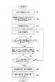
図1及び図2を参照して、駐車支援装置1の動作の流れを図7のフローチャートに沿って説明する。図7は本実施の形態に係る駐車支援装置における動作の流れを示すフローチャートである。 With reference to FIG.1 and FIG.2, the flow of operation | movement of the
超音波センサ10a〜10dでは、一定時間毎に、超音波を利用して自車両の側方の障害物検出を行い、障害物を検出できた場合には障害物までの距離を検出し、その距離情報等をECU30に送信する。クリソナセンサ11a〜11hでは、一定時間毎に、超音波を利用して自車両の前方/後方の障害物検出を行い、障害物を検出できた場合には障害物までの距離を検出し、その距離情報等をECU30に送信する。 In the
駐車支援開始スイッチ12では、運転者の操作による駐車支援開始のON/OFFからなる駐車支援開始スイッチ情報を通信処理部40を介してECU30に送信する。駐車開始スイッチ13では、運転者の操作による駐車開始のON/OFFからなる駐車開始スイッチ情報を通信処理部40を介してECU30に送信する。 The parking support start
シフトポジションセンサ14では、運転者の操作によるシフトレバーのシフトポジションを検出し、シフトポジション情報を通信処理部40を介してECU30に送信する。ステアリングセンサ15では、一定時間毎に、舵角を検出し、舵角情報を通信処理部40を介してECU30に送信する。車輪速センサ16では、一定時間毎に、車輪速を検出し、車輪速情報を通信処理部40を介してECU30に送信する。Yaw−Gセンサ17では、一定時間毎に、ヨーレートや横Gを検出し、ヨーレート情報や横G情報を通信処理部40を介してECU30に送信する。 The
ECU30では、駐車支援開始スイッチ情報に基づいて駐車支援開始スイッチ12がONされたか否か判断し、ONと判断した場合には駐車支援を開始する(S1)。そして、ECU30では、自車両が前進中に、超音波センサ10a〜10dからの各検出情報及びクリソナセンサ11a〜11hからの各検出情報に基づいて自車両の左右側方の障害物を検出しながら、駐車位置を検出する(S2)。駐車位置を検出すると、ECU30では、アラーム音を発生させる。そして、ECU30では、駐車開始スイッチ情報に基づいて駐車開始スイッチ13がONされたか否か判断し、ONと判断した場合には駐車を開始する(S3)。 The
ECU30では、首振り前進制御用の前進経路を生成し、その前進経路に基づいて首振り前進制御を行い、目標舵角になるための目標電流量をEPS21に送信する(S4)。この目標電流量を受信すると、EPS21では、その目標電流量となるように電流量を制御してEPSモータに付加し、EPSモータを回転駆動する。これによって、タイヤが転舵し、自車両が自動的に操舵される。この首振り前進制御中に、ECU30では、実舵角と目標舵角に基づいてステアリングが軽くなる場所があるかの検出(低摩擦領域検出)を行い、ステアリングが軽くなる場所(低摩擦領域)があるか否かを判定する(S5)。 The
S5にてステアリングが軽くなる場所(低摩擦領域)があると判定した場合、ECU30では、そのステアリングが軽くなる場所で操舵できる経路が生成できるかを判断する(S6)。そして、ECU30では、自車両の現在の位置や現在の向きで駐車位置までの経路を生成できるか(特に、ステアリングが軽くなる場所があると判定した場合にはそのステアリングが軽くなる場所で操舵できる経路が生成できるか)を判定する(S7)。S7にて経路を生成できないと判定した場合、ECU30では、S4の処理に戻って、首振り前進制御を継続する。これによって、自車両の位置や向きが駐車位置までの経路を生成できるようになるまで、首振り前進制御が継続されるとともに低摩擦領域検出が行われる。なお、この前進中は、運転者はシフトレバーをDレンジに維持しており、運転者の操作によって自車両は前進(必要に応じて減速や停止)する。 When it is determined in S5 that there is a place where the steering becomes light (low friction region), the
S7にて経路を生成できると判定した場合、ECU30では、駐車位置に自車両を駐車させるための後退経路を生成する(S8)。特に、ステアリングが軽くなる場所があると判定した場合、ステアリングが軽くなる低摩擦領域内で操舵を行う後退経路を生成する。そして、ECU30では、後退経路に基づいて操舵制御を行い、目標舵角になるための目標電流量をEPS21に送信する(S8)。この目標電流量を受信すると、EPS21では、その目標電流量となるように電流量を制御してEPSモータに付加し、EPSモータを回転駆動する(S8)。これによって、タイヤが転舵し、自車両が自動的に操舵される。特に、低摩擦領域がある場合、自車両は低摩擦領域の路面上で操舵される。この後退制御中にも、首振り前進制御中と同様に、ECU30では、実舵角と目標舵角に基づいてステアリングが軽くなる場所があるかの検出(低摩擦領域検出)を行ってもよい。そして、ECU30では、後退経路における駐車位置に自車両が到着したか否かを判断し、到着した場合(駐車完了の場合)には操舵制御を終了する(S9)。そして、ECU30では、システム(駐車支援)を終了させる(S9)。なお、この後退中は、運転者はシフトレバーをRレンジに切り替え、運転者の操作によって自車両は後退(必要に応じて減速や停止)する。 If it is determined in S7 that the route can be generated, the
なお、後退制御中に、切り返しが行われた場合(後退中に運転者がシフトレバーをRレンジからDレンジに切り替えて再度前進した場合)、S4の首振り前進制御に戻って、上記と同様の動作を繰り返す。特に、後退制御中にステアリングが軽くなる場所(低摩擦領域)があると判定した場合にはそのステアリングが軽くなる場所で操舵する首振り前進制御用の前進経路に修正する。また、切り返し後の首振り前進制御中に新たにステアリングが軽くなる場所があると判定した場合にはそのステアリングが軽くなる場所で操舵する後退経路に修正する。 In addition, when the turning-back is performed during the reverse control (when the driver moves forward again by switching the shift lever from the R range to the D range during the reverse control), the control returns to the swing forward control of S4 and is the same as above. Repeat the operation. In particular, when it is determined that there is a place where the steering is lightened (low friction region) during the reverse control, the travel path is corrected to a swing forward control for steering at a place where the steering is lightened. Further, when it is determined that there is a place where the steering becomes lighter during the swing forward control after turning back, it is corrected to the backward path for steering at the place where the steering becomes light.
この駐車支援装置1によれば、駐車支援開始後に低摩擦領域の検出を行い、低摩擦領域を検出できた場合には低摩擦領域内で操舵する駐車経路を生成して操舵制御を行うことにより、操舵に必要な電流量を少なくでき、EPS21での負荷を低減できる。これによって、EPS21での発熱量も抑えることができるとともに、消費電流量を低減できる。 According to the parking assist
また、駐車支援装置1によれば、首振り前進制御中の目標舵角と実舵角とを比較することによって低摩擦領域検出を行うことにより、低摩擦領域を簡単かつ高精度に検出できる。この検出方法の場合、低摩擦領域を検出するために別途のセンサ等を必要としない。 Moreover, according to the
ちなみに、従来の駐車支援では、低摩擦領域が検出された場合、低摩擦領域は駐車経路に沿って車両を操舵するのに障害となると考えられていたので、低摩擦領域を回避するような駐車経路が生成されていた。しかし、駐車支援装置1では、低摩擦領域をメリットと考えて、低摩擦領域を有効に利用している。 Incidentally, in the conventional parking assistance, when a low friction area is detected, the low friction area is considered to be an obstacle to steering the vehicle along the parking route, so that parking that avoids the low friction area is considered. A route was being generated. However, the
以上、本発明に係る実施の形態について説明したが、本発明は上記実施の形態に限定されることなく様々な形態で実施される。 As mentioned above, although embodiment which concerns on this invention was described, this invention is implemented in various forms, without being limited to the said embodiment.
例えば、本実施の形態では操舵制御で駐車支援を行う駐車支援装置に適用したが、他の支援形態でもよく、例えば、操舵制御に加えてエンジン制御やブレーキ制御による駐車支援、駐車経路を表示や音声等による情報提供による駐車支援に適用してもよい。 For example, in this embodiment, the present invention is applied to a parking assistance device that performs parking assistance by steering control. However, other assistance forms may be used, for example, parking assistance by engine control or brake control in addition to steering control, You may apply to the parking assistance by the information provision by an audio | voice etc.
また、本実施の形態では低摩擦領域の検出方法として目標舵角と実舵角とを比較することによって検出する方法を示したが、他の検出方法でもよく、例えば、カメラで車両周辺を撮像し、撮像画像を画像処理して低い摩擦係数の要因となるもの(マンホール、排水溝、水溜り、白線等)を検出する方法、各輪の車輪速と車体速等から走行中の路面の摩擦係数を推定し、推定摩擦係数が閾値以下の場合に低摩擦領域と判定する方法がある。 Further, in the present embodiment, the detection method by comparing the target rudder angle and the actual rudder angle is shown as a detection method of the low friction region. However, other detection methods may be used, for example, the camera periphery is imaged with a camera. Then, the captured image is processed to detect low friction coefficient factors (manholes, drains, puddles, white lines, etc.), the road surface friction from the wheel speed and body speed of each wheel, etc. There is a method of estimating the coefficient and determining the low friction region when the estimated friction coefficient is equal to or less than a threshold value.
また、本実施の形態では車両を後退で駐車させる駐車支援について説明したが、車両を前進で駐車させる駐車支援についても適用でき、この場合には後退経路に沿った操舵制御中に低摩擦領域を検出し、低摩擦領域を検出した場合にその低摩擦領域内で操舵を行う前進経路を生成する。 Further, in the present embodiment, the parking assistance for parking the vehicle in the backward direction has been described, but the parking assistance for parking the vehicle in the forward direction can also be applied. In this case, the low friction region is set during the steering control along the backward path. When a low friction region is detected, a forward path for steering in the low friction region is generated.
また、本実施の形態では駐車位置を検出すると、基準となる前進経路を生成し、前進経路に沿って首振り前進制御を行った後に、後退経路を生成し(この際、首振り前進制御中に低摩擦領域を検出している場合には低摩擦領域内で操舵する後退経路とする)、後退経路に沿って後退制御を行う構成としたが、駐車位置を検出すると、基準となる前進経路及び後退経路を生成しておき、前進経路に沿って首振り前進制御を行い、首振り前進制御中に低摩擦領域を検出している場合には後退経路を低摩擦領域内で操舵する後退経路に修正し、後退経路に沿って後退制御を行う構成としてもよい。 In this embodiment, when the parking position is detected, a reference forward path is generated, and after swinging forward control is performed along the forward path, a backward path is generated (in this case, the swing forward control is being performed). When the low friction area is detected, the reverse path is steered within the low friction area), but the reverse control is performed along the reverse path. However, when the parking position is detected, the reference forward path And a backward path for generating a backward path, performing a swing forward control along the forward path, and steering the reverse path within the low friction area when the low friction area is detected during the forward swing control. It is good also as a structure which reversely corrects and performs reverse control along a reverse path | route.
1…駐車支援装置、10a〜10d…超音波センサ、11a〜11h…クリソナセンサ、12…駐車支援開始スイッチ、13…駐車開始スイッチ、14…シフトポジションセンサ、15…ステアリングセンサ、16…車輪速センサ、17…Yaw−Gセンサ、20…ディスプレイ、21…EPS、30…ECU、31…駐車空間検出部、32…前向き駐車経路制御部、33…後向き駐車経路制御部、40…通信処理部。 DESCRIPTION OF
Claims (4)
Translated fromJapanese駐車位置を検出する駐車位置検出手段と、
前記駐車位置検出手段で検出した駐車位置に操舵によって自車両を駐車させるための駐車経路を生成する駐車経路生成手段と、
前記駐車経路生成手段で生成した駐車経路を用いて駐車支援を行う駐車支援手段と、
駐車支援開始から終了するまでの間で路面摩擦係数が局所的に低い低摩擦領域を検出する低摩擦領域検出手段と、
を備え、
前記駐車経路生成手段は、前記低摩擦領域検出手段で低摩擦領域を検出した場合に当該低摩擦領域内で操舵を行う駐車経路を生成することを特徴とする駐車支援装置。A parking assistance device that provides parking assistance for parking the host vehicle at a parking position,
Parking position detection means for detecting the parking position;
Parking path generation means for generating a parking path for parking the host vehicle by steering at the parking position detected by the parking position detection means;
Parking assistance means for providing parking assistance using the parking route generated by the parking route generation means;
Low friction area detection means for detecting a low friction area where the road surface friction coefficient is locally low between the start and end of parking assistance;
With
The parking route generation device generates a parking route for performing steering in the low friction region when the low friction region is detected by the low friction region detection unit.
前記低摩擦領域検出手段は、前進経路に沿った駐車支援中に低摩擦領域を検出し、
前記駐車経路生成手段は、前記低摩擦領域検出手段で低摩擦領域を検出した場合に後退経路を当該低摩擦領域内で操舵を行う後退経路に修正することを特徴とする請求項1に記載の駐車支援装置。The parking route generated by the parking route generating means includes a backward route when the host vehicle moves backward and a forward route when the host vehicle moves forward,
The low friction region detection means detects a low friction region during parking assistance along the forward path,
The said parking path | route production | generation means corrects a reverse path | route to the reverse path | route which steers within the said low friction area | region, when the low friction area | region detection means detects a low friction area | region. Parking assistance device.
前記低摩擦領域検出手段は、後退経路に沿った駐車支援中に低摩擦領域を検出し、
前記駐車経路生成手段は、前記低摩擦領域検出手段で低摩擦領域を検出した場合に前進経路を当該低摩擦領域内で操舵を行う前進経路に修正することを特徴とする請求項1に記載の駐車支援装置。The parking route generated by the parking route generating means includes a backward route when the host vehicle moves backward and a forward route when the host vehicle moves forward,
The low friction area detection means detects a low friction area during parking assistance along a backward path,
The said parking path | route production | generation means corrects an advance path | route to the advance path | route which steers within the said low friction area | region, when the low friction area | region detection means detects a low friction area | region. Parking assistance device.
Priority Applications (1)
| Application Number | Priority Date | Filing Date | Title |
|---|---|---|---|
| JP2013102221AJP2014221615A (en) | 2013-05-14 | 2013-05-14 | Parking assisting device |
Applications Claiming Priority (1)
| Application Number | Priority Date | Filing Date | Title |
|---|---|---|---|
| JP2013102221AJP2014221615A (en) | 2013-05-14 | 2013-05-14 | Parking assisting device |
Publications (1)
| Publication Number | Publication Date |
|---|---|
| JP2014221615Atrue JP2014221615A (en) | 2014-11-27 |
Family
ID=52121410
Family Applications (1)
| Application Number | Title | Priority Date | Filing Date |
|---|---|---|---|
| JP2013102221APendingJP2014221615A (en) | 2013-05-14 | 2013-05-14 | Parking assisting device |
Country Status (1)
| Country | Link |
|---|---|
| JP (1) | JP2014221615A (en) |
Cited By (1)
| Publication number | Priority date | Publication date | Assignee | Title |
|---|---|---|---|---|
| WO2019244490A1 (en)* | 2018-06-22 | 2019-12-26 | 日立オートモティブシステムズ株式会社 | Vehicle control device |
- 2013
- 2013-05-14JPJP2013102221Apatent/JP2014221615A/enactivePending
Cited By (5)
| Publication number | Priority date | Publication date | Assignee | Title |
|---|---|---|---|---|
| WO2019244490A1 (en)* | 2018-06-22 | 2019-12-26 | 日立オートモティブシステムズ株式会社 | Vehicle control device |
| CN112313128A (en)* | 2018-06-22 | 2021-02-02 | 日立汽车系统株式会社 | Vehicle control device |
| JPWO2019244490A1 (en)* | 2018-06-22 | 2021-06-03 | 日立Astemo株式会社 | Vehicle control device |
| JP7005757B2 (en) | 2018-06-22 | 2022-01-24 | 日立Astemo株式会社 | Vehicle control device |
| CN112313128B (en)* | 2018-06-22 | 2024-09-27 | 日立安斯泰莫株式会社 | Vehicle control device |
Similar Documents
| Publication | Publication Date | Title |
|---|---|---|
| JP4582052B2 (en) | Driving support device | |
| JP5975172B2 (en) | Parking assistance device | |
| JP4946631B2 (en) | Start support device, display device | |
| US20100332080A1 (en) | Method and apparatus for parking assistance | |
| JP4900174B2 (en) | Parking assistance device, parking assistance method, and computer program | |
| JP6836189B2 (en) | Steering support device | |
| JP2008207732A (en) | Drive assisting device | |
| JP2006264623A (en) | Lane keeping supporting device | |
| JP2008056173A (en) | Vehicle driving support device | |
| JP2007237838A (en) | Steering device, automobile, and steering control method | |
| JP5082905B2 (en) | Parking assistance device, parking assistance method, and computer program | |
| JP4816512B2 (en) | Driving assistance device | |
| JP5983276B2 (en) | Parking assistance device | |
| WO2017135191A1 (en) | Parking assistance method | |
| JP5962598B2 (en) | Parking assistance device and parking assistance method | |
| JP2014024462A (en) | Parking support device | |
| JP2018135028A (en) | Parking assistance device | |
| JP2011100184A (en) | Parking assist device | |
| JP2009166764A (en) | Vehicle contact avoidance support device | |
| JP2006193011A (en) | Parking assistance device | |
| JP6705413B2 (en) | Automatic driving system | |
| CN107792175A (en) | Outbound servicing unit | |
| JP4023478B2 (en) | Parking assistance system | |
| JP2014043139A (en) | Parking assistance device | |
| JP2014221615A (en) | Parking assisting device |