JP2014221400A - Patient positioning support structure - Google Patents
Patient positioning support structureDownload PDFInfo
- Publication number
- JP2014221400A JP2014221400AJP2014142074AJP2014142074AJP2014221400AJP 2014221400 AJP2014221400 AJP 2014221400AJP 2014142074 AJP2014142074 AJP 2014142074AJP 2014142074 AJP2014142074 AJP 2014142074AJP 2014221400 AJP2014221400 AJP 2014221400A
- Authority
- JP
- Japan
- Prior art keywords
- support
- patient
- end portion
- supports
- patient support
- Prior art date
- Legal status (The legal status is an assumption and is not a legal conclusion. Google has not performed a legal analysis and makes no representation as to the accuracy of the status listed.)
- Pending
Links
Images


Classifications
- A—HUMAN NECESSITIES
- A61—MEDICAL OR VETERINARY SCIENCE; HYGIENE
- A61G—TRANSPORT, PERSONAL CONVEYANCES, OR ACCOMMODATION SPECIALLY ADAPTED FOR PATIENTS OR DISABLED PERSONS; OPERATING TABLES OR CHAIRS; CHAIRS FOR DENTISTRY; FUNERAL DEVICES
- A61G7/00—Beds specially adapted for nursing; Devices for lifting patients or disabled persons
- A61G7/002—Beds specially adapted for nursing; Devices for lifting patients or disabled persons having adjustable mattress frame
- A61G7/012—Beds specially adapted for nursing; Devices for lifting patients or disabled persons having adjustable mattress frame raising or lowering of the whole mattress frame
- A—HUMAN NECESSITIES
- A61—MEDICAL OR VETERINARY SCIENCE; HYGIENE
- A61G—TRANSPORT, PERSONAL CONVEYANCES, OR ACCOMMODATION SPECIALLY ADAPTED FOR PATIENTS OR DISABLED PERSONS; OPERATING TABLES OR CHAIRS; CHAIRS FOR DENTISTRY; FUNERAL DEVICES
- A61G13/00—Operating tables; Auxiliary appliances therefor
- A61G13/02—Adjustable operating tables; Controls therefor
- A61G13/08—Adjustable operating tables; Controls therefor the table being divided into different adjustable sections
- A—HUMAN NECESSITIES
- A61—MEDICAL OR VETERINARY SCIENCE; HYGIENE
- A61B—DIAGNOSIS; SURGERY; IDENTIFICATION
- A61B6/00—Apparatus or devices for radiation diagnosis; Apparatus or devices for radiation diagnosis combined with radiation therapy equipment
- A61B6/04—Positioning of patients; Tiltable beds or the like
- A61B6/0407—Supports, e.g. tables or beds, for the body or parts of the body
- A61B6/0421—Supports, e.g. tables or beds, for the body or parts of the body with immobilising means
- A—HUMAN NECESSITIES
- A61—MEDICAL OR VETERINARY SCIENCE; HYGIENE
- A61B—DIAGNOSIS; SURGERY; IDENTIFICATION
- A61B6/00—Apparatus or devices for radiation diagnosis; Apparatus or devices for radiation diagnosis combined with radiation therapy equipment
- A61B6/04—Positioning of patients; Tiltable beds or the like
- A61B6/0487—Motor-assisted positioning
- A—HUMAN NECESSITIES
- A61—MEDICAL OR VETERINARY SCIENCE; HYGIENE
- A61G—TRANSPORT, PERSONAL CONVEYANCES, OR ACCOMMODATION SPECIALLY ADAPTED FOR PATIENTS OR DISABLED PERSONS; OPERATING TABLES OR CHAIRS; CHAIRS FOR DENTISTRY; FUNERAL DEVICES
- A61G13/00—Operating tables; Auxiliary appliances therefor
- A61G13/0018—Physician's examining tables
- A—HUMAN NECESSITIES
- A61—MEDICAL OR VETERINARY SCIENCE; HYGIENE
- A61G—TRANSPORT, PERSONAL CONVEYANCES, OR ACCOMMODATION SPECIALLY ADAPTED FOR PATIENTS OR DISABLED PERSONS; OPERATING TABLES OR CHAIRS; CHAIRS FOR DENTISTRY; FUNERAL DEVICES
- A61G13/00—Operating tables; Auxiliary appliances therefor
- A61G13/0036—Orthopaedic operating tables
- A61G13/0054—Orthopaedic operating tables specially adapted for back or spinal surgeries
- A—HUMAN NECESSITIES
- A61—MEDICAL OR VETERINARY SCIENCE; HYGIENE
- A61G—TRANSPORT, PERSONAL CONVEYANCES, OR ACCOMMODATION SPECIALLY ADAPTED FOR PATIENTS OR DISABLED PERSONS; OPERATING TABLES OR CHAIRS; CHAIRS FOR DENTISTRY; FUNERAL DEVICES
- A61G13/00—Operating tables; Auxiliary appliances therefor
- A61G13/02—Adjustable operating tables; Controls therefor
- A61G13/04—Adjustable operating tables; Controls therefor tiltable around transverse or longitudinal axis
- A—HUMAN NECESSITIES
- A61—MEDICAL OR VETERINARY SCIENCE; HYGIENE
- A61G—TRANSPORT, PERSONAL CONVEYANCES, OR ACCOMMODATION SPECIALLY ADAPTED FOR PATIENTS OR DISABLED PERSONS; OPERATING TABLES OR CHAIRS; CHAIRS FOR DENTISTRY; FUNERAL DEVICES
- A61G13/00—Operating tables; Auxiliary appliances therefor
- A61G13/02—Adjustable operating tables; Controls therefor
- A61G13/06—Adjustable operating tables; Controls therefor raising or lowering of the whole table surface
- A—HUMAN NECESSITIES
- A61—MEDICAL OR VETERINARY SCIENCE; HYGIENE
- A61G—TRANSPORT, PERSONAL CONVEYANCES, OR ACCOMMODATION SPECIALLY ADAPTED FOR PATIENTS OR DISABLED PERSONS; OPERATING TABLES OR CHAIRS; CHAIRS FOR DENTISTRY; FUNERAL DEVICES
- A61G7/00—Beds specially adapted for nursing; Devices for lifting patients or disabled persons
- A61G7/001—Beds specially adapted for nursing; Devices for lifting patients or disabled persons with means for turning-over the patient
- A—HUMAN NECESSITIES
- A61—MEDICAL OR VETERINARY SCIENCE; HYGIENE
- A61G—TRANSPORT, PERSONAL CONVEYANCES, OR ACCOMMODATION SPECIALLY ADAPTED FOR PATIENTS OR DISABLED PERSONS; OPERATING TABLES OR CHAIRS; CHAIRS FOR DENTISTRY; FUNERAL DEVICES
- A61G7/00—Beds specially adapted for nursing; Devices for lifting patients or disabled persons
- A61G7/002—Beds specially adapted for nursing; Devices for lifting patients or disabled persons having adjustable mattress frame
- A61G7/008—Beds specially adapted for nursing; Devices for lifting patients or disabled persons having adjustable mattress frame tiltable around longitudinal axis, e.g. for rolling
Landscapes
- Health & Medical Sciences (AREA)
- Life Sciences & Earth Sciences (AREA)
- Engineering & Computer Science (AREA)
- Animal Behavior & Ethology (AREA)
- General Health & Medical Sciences (AREA)
- Public Health (AREA)
- Veterinary Medicine (AREA)
- Biomedical Technology (AREA)
- Medical Informatics (AREA)
- Orthopedic Medicine & Surgery (AREA)
- Nursing (AREA)
- Pathology (AREA)
- High Energy & Nuclear Physics (AREA)
- Nuclear Medicine, Radiotherapy & Molecular Imaging (AREA)
- Optics & Photonics (AREA)
- Physics & Mathematics (AREA)
- Radiology & Medical Imaging (AREA)
- Heart & Thoracic Surgery (AREA)
- Molecular Biology (AREA)
- Surgery (AREA)
- Biophysics (AREA)
- Neurology (AREA)
- Neurosurgery (AREA)
- Accommodation For Nursing Or Treatment Tables (AREA)
Abstract
Description
Translated fromJapanese [0001] 本発明は、画像化及び外科手術のような、医療方法を含んで、検査及び治
療の間、患者を所望の位置に維持するとき使用される構造体に関し、特に、仰向け位置、
うつ伏せ位置又は側方位置にて患者の体幹及び(又は)関節の傾動、回動、角度動作又は
曲がりを含む、外科手術の間、外科医が手術箇所に便宜にアクセスし得るよう患者を選択
的に配置し且つ、患者を操作することを可能にすることを許容する、かかる構造体に関す
る。[0001] The present invention relates to structures used when maintaining a patient in a desired position during examination and treatment, including medical methods, such as imaging and surgery, in particular, supine positions,
Select patients for convenient access by the surgeon during surgery, including tilting, pivoting, angular movement or bending of the patient's trunk and / or joints in a prone or lateral position And to such a structure that allows to be manipulated by the patient.
[0002] 現代の外科手術法は、患者の検査、診断又は治療の過程の全体にわたっ
て画像化法及び技術を含む。例えば、脊柱インプラントの経皮的挿入のような、最小侵襲
外科技術は、手術間の連続的又は反復的な画像化によって案内して小切開を行なうことを
含む。これらの像は、処置の過程の間、外科医が参照するための三次元的像を生成するコ
ンピュータソフトウェアプログラムを使用して処理することができる。患者の支持面が放
射線透過性でなく又は画像化技術と適合しない場合、外科手術を定期的に中断して、患者
を画像化のため別個の面に移し、その後、外科手術を再開するため、手術支持面に移送し
て戻すことが必要となる。画像化目的のためかかる患者の移送は、放射線透過性及びその
他の画像化適合可能なシステムを採用することにより回避することができる。患者の支持
システムは、また、滅菌野を汚すことなく、外科手術の過程の全体にわたって画像化装置
及びその他の外科的装置を患者の回り、患者の上又は下にて妨害されずに動くことを許容
するような構造としなければならない。[0002] Modern surgical methods include imaging methods and techniques throughout the course of patient examination, diagnosis or treatment. For example, minimally invasive surgical techniques, such as percutaneous insertion of spinal implants, include guided small incisions through continuous or repetitive imaging between operations. These images can be processed using a computer software program that generates a three-dimensional image for reference by the surgeon during the course of the procedure. If the patient's support surface is not radiolucent or incompatible with the imaging technique, the surgery is periodically interrupted to transfer the patient to a separate surface for imaging and then resume surgery. It must be transferred back to the surgical support surface. Such patient transfer for imaging purposes can be avoided by employing radiolucent and other imaging compatible systems. The patient support system also ensures that the imaging device and other surgical devices can move unobstructed around, above or below the patient throughout the course of surgery without contaminating the sterile field. The structure must be acceptable.
[0003] また、患者の支持システムは、外科チームによる手術野への最適なアク
セスを提供するような構造とする必要もある。幾つかの処置法は、手術中、異なる時点に
て異なる仕方にて患者の身体の部分を位置決めすることを必要とする。幾つかの処置法、
例えば、脊柱手術は、1つ以上の手術部位又は手術野を通してアクセスすることを含む。
これらの野の全ては、同一の平面又は解剖学的位置にはないので、患者の支持面は、調節
可能であり且つ、患者の身体の異なる部分に対して異なる平面内にてのみならず、身体の
所定の部分に対する異なる位置又は整合状態にて支持作用を提供することができなければ
ならない。好ましくは、支持面は、患者の身体の頭部及び上体幹部分、身体の下体幹部分
及び骨盤部分のみならず、肢体の各々に対して独立的に別個の平面及び異なる整合状態を
提供し得るよう調節可能であるものとする。[0003] The patient support system also needs to be structured to provide optimal access to the surgical field by the surgical team. Some procedures require positioning parts of the patient's body in different ways at different times during surgery. Several treatments,
For example, spinal surgery involves accessing through one or more surgical sites or fields.
Not all of these fields are in the same plane or anatomical position, so that the patient support surface is adjustable and not only in different planes for different parts of the patient's body, It should be possible to provide support at different positions or alignments for a given part of the body. Preferably, the support surface provides a separate plane and different alignment for each of the limbs as well as the head and upper trunk portions of the patient's body, the lower trunk portion and the pelvis portion of the body. It shall be adjustable to obtain.
[0004] 整形外科手術のような、特定型式の外科手術は、患者又は患者の一部分
を、場合によっては、滅菌野に維持しつつ、手術の間、再位置決めすることを必要とする
であろう。外科手術が、例えば、人工関節、脊柱靭帯及び全椎間板補綴具を取り付けるこ
とに等より、動作を保存する処置法を目的とする場合、外科医は、外科手術中、手術を容
易にするため、患者の身体の選んだ部分を支持しつつ、特定の関節を操作し得なければな
らない。外科手術により修復され又は安定させた関節の運動範囲を試験し且つ、傷口が閉
じられる前に、再構築した関節動作式補綴具の面の滑動、又は人工靭帯、分離板、及びそ
の他の型式の動的安定器の張力及び可撓性を観察し得ることが望ましい。外科手術の間、
かかる操作を使用して、例えば、植え込んだ補綴椎間板、脊柱の動的長手方向接続部材、
脊柱間分離板又は代用関節の正確な位置決め及び機能を確認することができる。骨粗鬆症
の場合に生じるように、操作が例えば、隣接する椎骨の食い込み、最適でない位置にあり
又は潰れてさえもいることを明らかにする場合、患者に麻酔のかかっている間、補綴具を
除去し且つ、隣接する椎骨を融合させることができる。さもなければ、インプラントの術
後の「試験的」使用に起因するであろう損傷は回避され、また、インプラント又は補綴具
を除去し且つ、修正、融合又は矯正外科手術を行なうため二回目の麻酔及び外科手術の必
要性は回避されるであろう。[0004] Certain types of surgery, such as orthopedic surgery, may require repositioning the patient or portion of the patient during the procedure, possibly in a sterile field. . If the surgical procedure is aimed at a procedure that preserves motion, for example, by attaching an artificial joint, spinal ligament and whole disc prosthesis, the surgeon may It must be possible to manipulate specific joints while supporting selected parts of the body. Test the range of motion of a joint that has been repaired or stabilized by surgery and before the wound is closed, sliding the face of the reconstructed articulating prosthesis, or artificial ligaments, separators, and other types of It is desirable to be able to observe the tension and flexibility of the dynamic ballast. During surgery
Using such operations, for example, implanted prosthetic discs, spinal column dynamic longitudinal connection members,
The exact positioning and function of the intervertebral disc or substitute joint can be verified. Remove the prosthesis while the patient is anesthetized, such as when the manipulation reveals that the adjacent vertebrae are biting in, suboptimal or even collapsed, as occurs in the case of osteoporosis In addition, adjacent vertebrae can be fused. Otherwise, damage that would result from post-trial “experimental” use of the implant is avoided, and a second anesthesia is used to remove the implant or prosthesis and perform a correction, fusion or orthopedic surgery. And the need for surgery will be avoided.
[0005] 患者をうつ伏せ位置から仰向け位置まで又は、うつ伏せ位置から90°
の位置まで動かすことができ、これにより脊柱の少なくとも一部分の術間の伸び及び撓み
を実現することができるよう回転させ、関節接続し及び角度動作を可能にする患者の支持
面も必要とされる。患者の支持面は、また、患者を除去したり、又は手術を実質的に妨害
することを必要とせずに、容易に、選択的に調節できなければならない。[0005] From the prone position to the supine position or 90 ° from the prone position
There is also a need for a patient support surface that can be moved to the position of the patient and thereby rotated, articulated and angularly movable to achieve interoperative stretch and deflection of at least a portion of the spinal column. . The patient support surface must also be easily and selectively adjustable without the need to remove the patient or substantially interfere with the surgery.
[0006] 例えば、脊柱外科手術のような、特定型式の外科手術の場合、患者を順
序的な前方及び後方手術法のため位置決めすることが望ましいことがある。患者の支持面
は、かかる順序的な手術の間、軸線の回りにて回転し、患者を適正に位置決めし且つ外科
医のみならず、画像化装置に対しても最適なアクセス可能性を提供することもできなけれ
ばならない。[0006] For certain types of surgery, such as spinal surgery, it may be desirable to position the patient for sequential anterior and posterior surgical procedures. The patient support surface rotates about the axis during such sequential surgery to properly position the patient and provide optimal accessibility not only to the surgeon but also to the imaging device. Must also be able to.
[0007] 整形外科手術は、また、ケーブル、トング、プーリー及び重りのような
牽引装置を使用することを必要とすることもある。患者の支持システムは、かかる装置を
定着するための構造体を含み、また、かかる装置に対し牽引により発生された不均一な力
に耐えるのに十分な支持作用を提供しなければならない。[0007] Orthopedic surgery may also require the use of traction devices such as cables, tongs, pulleys and weights. The patient support system must include a structure for anchoring such a device and must provide sufficient support to withstand the non-uniform forces generated by traction on such a device.
[0008] 外科的技術を実行するため、関節動作式のロボットアームが益々、採用
されつつある。これらの装置は、全体として、短い距離を動き且つ、極めて精密な仕事を
行ない得るような設計とされている。患者の何らかの必要な全体的な動きを実行するため
患者支持構造体を利用することは、特に、その動きが同期化され又は同調される場合、有
益であろう。かかる装置は、さもなければ、訓練を受けた医療従事者が行なうであろう多
方向への動きを滑らかに行なうことができる外科的支持面を必要とする。このため、この
分野にてもロボット利用技術と患者の位置決め技術とを一体化する必要性が存する。[0008] Articulated robotic arms are increasingly being employed to perform surgical techniques. These devices as a whole are designed to move over a short distance and perform extremely precise work. Utilizing the patient support structure to perform any necessary overall movement of the patient may be beneficial, especially when the movement is synchronized or synchronized. Such a device requires a surgical support surface that can smoothly perform the multi-directional movement that would otherwise be performed by a trained medical professional. For this reason, there is a need to integrate robot utilization technology and patient positioning technology also in this field.
[0009] 従来の手術台は、全体として、患者の支持面が長手方向軸線の周りにて
傾動し又は回転することを許容する構造体を含むが、従来の外科手術支持装置は、一端に
片持ち式の患者の支持面を提供することにより、アクセスの必要性に対応しようと試みて
いた。かかる設計は、典型的に、伸びた支持部材に釣合うため大型の基部か、又は上方か
ら支持力を提供するため大型の頭上フレーム構造体の何れかを採用する。かかる片持ち式
設計と関係した拡大した基部材は、Cアーム及びOアームの可動の蛍光透視画像化装置及
びその他の装置の運動を妨げる可能性があり、また、妨げている点にて問題である。頭上
フレーム構造体を有する外科手術台は、大型であり、また、幾つかの場合、これらは、邪
魔にならない位置に容易に動かすことはできないから、専用の手術室を使用することを必
要とする。これらの設計の何れも容易に持運び型又は格納可能とすることはできない。[0009] While a conventional operating table generally includes a structure that allows a patient support surface to tilt or rotate about a longitudinal axis, a conventional surgical support device has a piece at one end. Attempts have been made to address the need for access by providing a portable patient support surface. Such designs typically employ either a large base to balance the extended support member or a large overhead frame structure to provide support from above. Enlarged base members associated with such cantilevered designs can interfere with and prevent movement of movable C- and O-arm movable fluoroscopic imaging devices and other devices. is there. Surgical tables with overhead frame structures are large and in some cases they cannot be easily moved to an unobstructed position, requiring the use of a dedicated operating room . None of these designs can be easily portable or retractable.
[0010] このように、人間及び装置に容易にアクセスすることを可能にし、また
、大型の釣合わせ式の支持構造体を使用せずに、多数の面内にて容易に、迅速に位置決め
し且つ再位置決めし、また、専用の手術室を使用する必要のない患者の支持システムを提
供する必要性がある。[0010] In this manner, humans and devices can be easily accessed, and positioning can be performed easily and quickly in multiple planes without the use of a large counterbalanced support structure. There is a need to provide a patient support system that repositions and does not require the use of a dedicated operating room.
[0011] 本発明は、傾動、回転、角度動作又は曲がり及びその他の操作を許容し
つつ、患者の頭部、上半身、下半身及び肢体を複数の個々の平面まで調節可能に位置決め
し、再位置決めし且つ選択的に係止可能に支持することを許容するのみならず、医療従事
者及び装置による患者への完全で且つ自由なアクセスを許容する患者の支持システムに関
するものである。本発明のシステムは、片持ち式でも又は非片持ち式でもよく、また、高
さが調節可能な少なくとも1つの支持端又はコラムを含む。図示した実施の形態は、1対
の対向した独立的に高さ調節可能な端部支持コラムを含む。コラムは、独立的とし、又は
、水平方向長さが調節可能な基部と接続してもよい。本発明に従った1つの支持コラムは
、壁マウント又はその他の静止支持体と連結することができる。患者支持構造体は、対の
端部支持体と接続され且つその支持体間を実質的に架橋する。例えば、本発明に従った1
つの実施の形態において、患者支持構造体は、端部支持体間にてヒンジ止め式に懸架され
ている。[0011] The present invention positions and repositions the patient's head, upper body, lower body, and limbs to multiple individual planes while allowing tilting, rotation, angular motion or bending and other manipulations. It also relates to a patient support system that not only allows selectively lockable support, but also allows complete and free access to the patient by medical personnel and devices. The system of the present invention may be cantilevered or non-cantilevered and includes at least one support end or column of adjustable height. The illustrated embodiment includes a pair of opposed independently height adjustable end support columns. The column may be independent or connected to a base with adjustable horizontal length. One support column according to the present invention can be coupled to a wall mount or other stationary support. The patient support structure is connected to the pair of end supports and substantially bridges between the supports. For example, according to the
In one embodiment, the patient support structure is hingedly suspended between the end supports.
[0012] 患者支持構造体は、半規制されたフレーム又はその他の患者の支持体を
有しており、フレーム又は患者の支持体は、少なくとも第一及び第二のヒンジ止め式部分
又はその他の接合し又は接続した部分を有し、第一及び第二の部分は、従来の規制され又
は固定された患者支持構造体に類似した、支持構造体の長手方向軸線に沿って第一の実質
的に平面状の向きにて選択的に係止可能である。しかし、本発明のヒンジ止め式又は半規
制された支持構造体は、互いに対して複数の角度にて位置決め可能で且つ係止可能な第一
及び第二の部分を提供し、その部分の各々は、第一の平面状の向きの両側部の位置まで可
動である。換言すれば、患者支持構造体は、水平な開始位置から上方又は下方の何れかに
て、また、1つの支持コラムが構造体の一端を他端よりも上方に持ち上げることに起因し
て支持構造体が傾斜位置又は非傾斜位置にあるとき、ヒンジ止めし又はさもなければ曲が
って角度運動部、折れ部(break)すなわち継手を形成することができる。更に、「
上昇」又は「下降」折れ部に加えて、2つの部分により形成された折れ部すなわち継手は
、支持構造体がその長手方向軸線の回りにて回転したときのように、側方向に向き決めす
ることができる。[0012] The patient support structure includes a semi-regulated frame or other patient support, the frame or patient support including at least first and second hinged portions or other joints. Or the first and second portions are substantially first along the longitudinal axis of the support structure, similar to a conventional regulated or fixed patient support structure. It can be selectively locked in a planar direction. However, the hinged or semi-restricted support structure of the present invention provides first and second portions that can be positioned and locked at a plurality of angles with respect to each other, each of the portions being It is movable to the position of both sides of the first planar orientation. In other words, the patient support structure is either above or below the horizontal starting position and because one support column lifts one end of the structure above the other end. When the body is in a tilted or non-tilted position, it can be hinged or otherwise bent to form an angular motion, a break or joint. In addition, "
In addition to the “up” or “down” fold, the fold or joint formed by the two parts orients laterally as when the support structure rotates about its longitudinal axis. be able to.
[0013] 特定の図示した実施の形態において、対の静止端部支持体間の中央位置
における患者支持構造体の関節接続部、継手又は折れ部は、ケーブル駆動システム(張力
バンド架橋装置)により支えられている。別の実施の形態において、プル−ロッド組立体
は、関節接続部を支えて折れ又は関節動作角度を制御し且つ、患者支持構造体を剛性にす
る。かかる実施の形態は、患者の支持体の一端に配設された実質的に固定のスライダバー
を更に含み、患者支持構造体は、かかるスライダバーにより支持され且つスライダバーに
沿って摺動可能に動くことができ、バーは、かかる端部にて患者を支持する傾動角度に従
う。その他の実施の形態は、可動又は伸縮式の基部支持体が接続されるか又は接続されな
い片持ち式システムも含む。第一及び第二の患者支持構造体の部分は、患者を保持する支
持パッドを設けることのできる矩形のフレーム又はその他の支持構造体、又は平坦面を提
供する画像化トップのような、その他の構造体の如きフレームの形態とすることができる
。[0013] In certain illustrated embodiments, the articulation, joint or fold of the patient support structure at a central location between the pair of stationary end supports is supported by a cable drive system (tension band bridging device). It has been. In another embodiment, the pull-rod assembly supports the joint connection to control the fold or articulation angle and to make the patient support structure rigid. Such embodiments further include a substantially fixed slider bar disposed at one end of the patient support, the patient support structure being supported by the slider bar and slidable along the slider bar. The bar can follow a tilt angle that supports the patient at such an end. Other embodiments also include cantilevered systems where a movable or telescopic base support is connected or not connected. The portions of the first and second patient support structures may be rectangular frames or other support structures that can be provided with support pads for holding the patient, or other such as imaging tops that provide a flat surface. It can be in the form of a frame such as a structure.
[0014] 患者支持構造体及び1つ又は複数の支持コラムは、それぞれの回転、関
節動作又は角度調節構造体と連結されて、第一の支持部分を第一のコラム、又は端部支持
体に対し且つ第二の支持部分に対し位置決めし、また、第二の支持部分を第二のコラム又
は端部支持体に対して位置決めする。回動及び高さ調節構造体と協働する回転調節構造体
は、第一及び第二の患者の支持部分を支持コラムに対して多岐にわたる選んだ位置及び関
節接続部にて係止可能に位置決めすることができ、これらの選んだ位置及び関節接続部は
、トレンデレンブルグ(Trendelenburg)及び逆トレンデレンブルグ(re
verse Trendelenburg)と連結された角度動作を含むのみならず、水
平方向又は傾動した向きにて患者が寝返りすることも可能にする。また、支承ブロック特
徴部によって側方向(外科医に向け且つ外科医から離れる方向への)動きを提供すること
もできる。1対の患者支持構造体(支持フレーム及び画像化台のような)は、本発明の端
部支持体間にて取り付け、その後、長手方向軸線の回りにて連動して回転させ、うつ伏せ
から仰向け位置まで患者の180°の再位置決めを実現することができる。[0014] The patient support structure and the one or more support columns are coupled to a respective rotation, articulation or angle adjustment structure to convert the first support portion into the first column or end support. And is positioned relative to the second support portion, and the second support portion is positioned relative to the second column or end support. The rotation adjustment structure, which cooperates with the rotation and height adjustment structure, positions the first and second patient support portions relative to the support column so that they can be locked at a variety of selected positions and joint connections. These selected positions and articulations can be defined as Trendelenburg and Reverse Trendelburg (re
In addition to including angular motion coupled to the Verse Trendelenburg), it also allows the patient to roll over in a horizontal or tilted orientation. The support block feature can also provide lateral movement (towards the surgeon and away from the surgeon). A pair of patient support structures (such as a support frame and an imaging platform) are mounted between the end supports of the present invention and then rotated in conjunction about the longitudinal axis so that they lie prone to supine A 180 ° repositioning of the patient to position can be achieved.
[0015] このため、本発明の1つの目的は、上述した患者の支持システムに伴う
1つ又はより多くの問題点を解決することである。本発明の更なる目的は、折れ又はヒン
ジ止め式の患者支持構造体を提供すること、かかる折れ又は継手が任意の所望の方向とな
るようにする、かかる構造体を提供すること、垂直方向の高さ調節を許容する少なくとも
1つの基部支持構造体を含む、かかる構造体を提供すること、かかる基部支持体が患者の
支持体の一端に配置される、かかる構造体を提供すること、多岐にわたる向きにて患者に
アクセスするため患者を位置決めし且つ隙間を許容すること、軸線の回りにて回転可能に
あるのみならず、その両端にて上方又は下方に動くことができる、かかる構造体を提供す
ること、容易に使用でき且つ、その所期の用途に特に適応し得るようにされて、また、比
較的経済的に製造でき且つ使用するのに適した装置及び方法を提供することを含む。[0015] Thus, one object of the present invention is to solve one or more of the problems associated with the patient support system described above. It is a further object of the present invention to provide a fold or hinged patient support structure, to provide such a structure that allows such folds or joints to be in any desired orientation, Providing such a structure comprising at least one base support structure that allows height adjustment, providing such a structure in which such base support is disposed at one end of a patient support, Providing such a structure that positions the patient to allow access to the patient in an orientation and allows clearance, is not only rotatable about the axis, but can move up or down at both ends thereof Providing an apparatus and method that is easy to use and is adapted to be particularly adapted to its intended use, and that can be manufactured relatively economically and is suitable for use. .
[0016] 本発明のその他の目的及び有利な点は、単に一例として、本発明の特定
の実施の形態を掲げる、添付図面と共に、以下の説明から明らかになるであろう。
[0017] 図面は、本明細書の一部を構成するものであり、また、本発明の一例と
しての実施の形態を含み、また、本発明の色々な目的及び特徴を示すものである。[0016] Other objects and advantages of the present invention will become apparent from the following description, taken in conjunction with the accompanying drawings, which illustrate, by way of example, specific embodiments of the invention.
[0017] The drawings form part of the present specification and include exemplary embodiments of the present invention and illustrate various objects and features of the present invention.
[0065] 要求されるように、本明細書にて本発明の詳細な実施の形態が開示され
ている。しかし、開示した実施の形態は、色々な形態にて具体化することができる本発明
の単に一例にしか過ぎないことを理解すべきである。このため、本明細書に開示された特
定の構造及び機能上の詳細は限定的ではなく、単に特許請求の範囲の基礎として且つ当該
技術の当業者に対しその実質的に任意の適正な詳細な構造にて本発明を色々に採用するこ
とを教示するための代表的な基本であると解釈されるべきである。[0065] As required, detailed embodiments of the present invention are disclosed herein. However, it is to be understood that the disclosed embodiments are merely exemplary of the invention, which can be embodied in various forms. As such, the specific structural and functional details disclosed herein are not limiting and merely serve as the basis for the claims and substantially any reasonable details to those skilled in the art. It should be construed as a representative basis for teaching various adoptions of the present invention in structure.
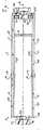
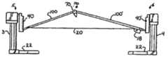
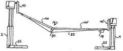
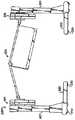
[0066] 次に、図面を参照すると、本発明に従った患者の位置決め支持構造体は
、全体として参照番号1で示されており、また、図1−図12に示されている。構造体1
は、図1に示したように、独立的な静止床基部支持構造体として示され、又は、図25−
図28に示した実施の形態にて図示されたように、非伸縮式基部支持体により互いに接続
することができる第一及び第二の直立の支持ピア又はコラム3、4を含む。例えば、図3
2−図34にて示したように、本発明に従った幾つかの実施の形態において、基部の接続
部は、コラムを選択的に伸縮可能な関係にて配置する。本発明に従った特定の実施の形態
において、支持コラムの1つは、従来の手術室の手術台にて置換し又は壁マウント部とす
ることさえも可能であると考えられる。第一の図示した実施の形態において、直立の支持
コラム3は、全体として参照番号5で示した第一の支持組立体と接続され、直立の支持コ
ラム4は、全体として参照番号6で示した第二の支持組立体と接続されている。両者の間
にて、支持組立体5、6は、全体として参照番号10で示した除去可能な細長い関節動作
式に接続し又は折れする患者の保持又は支持構造体を保持し、また、選択的に、本発明の
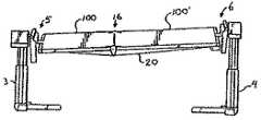
別の実施の形態に関して説明する第二の除去可能な患者支持構造体を保持する。図示した
支持構造体10は、第一のフレーム部分12と、横支持クロスバー15を有する第二のフ
レーム部分14と、全体として参照番号16で示したピボット又はヒンジ組立体とを含む
。図示した実施の形態において、ピボット組立体は、二重ウィンチ18と、協働するケー
ブル20とを含むケーブル駆動システムを更に含む。[0066] Referring now to the drawings, a patient positioning support structure according to the present invention is indicated generally by the
Is shown as an independent stationary floor base support structure, as shown in FIG.
As illustrated in the embodiment shown in FIG. 28, it includes first and second upstanding support peers or
2-As shown in FIG. 34, in some embodiments according to the present invention, the base connection places the columns in a selectively expandable relationship. In certain embodiments according to the present invention, it is contemplated that one of the support columns could be replaced with a conventional operating room operating table or even a wall mount. In the first illustrated embodiment, the
[0067] コラム3、4は、隔てられたキャスタ又はホイール(図示せず)を含み
又は含まなくてもよい外方に伸びる足部22により支持されており、キャスタ又はホイー
ルの各々には、足部12を図1に示したように、床係合位置まで下降させる床係止足部が
設けられている。コラム3、4の各々は、2つ又はより多くの伸縮式リフトアームセグメ
ント3a、3b、4a、4bをそれぞれ含み、これらのリフトアームセグメントは、コラ
ム3、4の各々の高さを選択的に加減して、接続された患者支持構造体10の全てを又は
選んだ部分を上昇及び下降することを許容する。垂直支持体3、4は、コラム3が支持コ
ラム4よりも大きい質量を有し又はその逆とし、人体の不均一な体重の配分に対応し得る
ような構造とすることも考えられる。システム1の足端部における寸法のかかる減少は、
幾つかの実施の形態において、人間及び装置のアプローチを容易にすべく採用することが
できる。[0067]
In some embodiments, a human and device approach can be employed to facilitate.
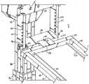
[0068] 支持組立体5、6の各々は、全体として、回転サブ組立体26、26´
と、角度サブ組立体27、27´とをそれぞれ含み、これらのサブ組立体は、以下に更に
詳細に説明するように、相互に接続されて、また、協働可能で且つ一体的な起動及び作動
のため、関係した電源と、コントローラ29(図1)に連結された回路とを含む。回転可
能なサブ組立体26、26´は、患者支持構造体10が構造体1の長手方向軸線の回りに
て同調して回転するのを可能にする。図2、図3に示した角度サブ組立体27、27´は
、所望のレベル及び漸増量にてヒンジ組立体16にて支持体10を選択的にヒンジ止めし
、関節動作し又は折れさせることを可能にするのみならず、フレーム部分12、14がか
かるフレーム部分の長手方向軸線に対して選択的に傾動することを可能にする。[0068] Each of the
And
[0069] 図1、図5に示した回転サブ組立体又は機構26は、支持コラム3の上
にある少なくとも1つのモータハウジング30を含む。図示した実施の形態において、1
つの回転モータのみが提供されているが、協働するモータは、支持コラム4に取り付ける
ことも可能であると考えられる。主回転軸32は、回転構造体33を回転させるモータハ
ウジング30から伸びている。一方、回転構造体33は、以下により詳細に説明するよう
に、接続された患者の支持体10を長手方向軸線の回りにて回転させる。モータハウジン
グ30は、軸32と駆動可能に係合した回転電気モータ又はその他のアクチュエータを収
容している。回転機構26は、スイッチ又はその他の同様の手段を使用してモータを起動
させることにより作動させる。回転構造体33は、モータハウジング30及び支持コラム
3から隔てられた位置にて軸32に固定され、接続された患者支持構造体10が回転する
ための隙間を提供する。[0069] The rotating subassembly or
Although only one rotary motor is provided, it is believed that cooperating motors can also be attached to the
[0070] 図4、図5に示したように、回転構造体33は、回転構造体33の両端
に配設された1対の並行移動ポスト又はHバーポスト40に装着されている。ポスト40
の各々は、ピン42、ボルト、その他の固定構造体により構造体33に装着されている。
ポスト40に形成された複数の協働する開口44は、ピボットピン46が貫通して伸びる
ための通路を提供する。ピボットピン46は、協働する対の開口44の各々に受け入れら
れ、対のポスト40の間に受け入れられ、また、ピボットピン46を受け入れる寸法及び
形状とされた並行移動コネクタ48を選択的に配置することを許容する。このように、ピ
ン46及びコネクタ48は、外科医が選択する多岐にわたる高さにて支持体10の長手方
向伸長体に対し横方向の向きにて位置決めし且つ、必要であれば、外科手術の間でさえ、
容易に変更してフレーム部分12の高さを変えることができる。例えば、図25−図29
に示したように、1つ以上のフレーム又は患者の構造体がタンデムに取り付けられたとき
にも、多数の位置又は高さの特徴は有益である。フレーム又はその他の構造体の位置は、
患者の体格又はその他の特徴、外科的又はその他の条件に依存して、拡張可能又は縮小可
能な患者の支持体と画像化トップとの間の距離にて画像化トップへの近接性を提供するよ
う望ましいように変更可能である。図5に示したように、コネクタ48は、ピボットピン
46を受け入れるスロット50を有する。As shown in FIGS. 4 and 5, the rotating
Each is mounted on the
A plurality of cooperating
The height of the
As shown, multiple position or height features are also beneficial when one or more frames or patient structures are attached in tandem. The position of the frame or other structure is
Provides proximity to the imaging top at a distance between the expandable or retractable patient support and the imaging top, depending on the patient's physique or other characteristics, surgical or other conditions It can be changed as desired. As shown in FIG. 5, the
[0071] 図4、図5も参照すると、一方、並行移動コネクタ48は、ピボットコ
ネクタ52に装着されている。ピボットコネクタ52は、第一及び第二の外方に開き且つ
対向したスロット54、56を含む。第一のスロット54は、並行移動コネクタ48を受
け入れる寸法及び形状とされ、第二のスロットは、フレーム部分12の端部接続部58を
受け入れる寸法及び形状とされている。ピボットコネクタ52は、スロット54に対し実
質的に垂直に伸び且つスロットと連通する貫通開口又はボア60を更に含む。開口60は
、ピボットピン62を受け入れ得る寸法及び形状とされている。コネクタ48は、ピボッ
トピン62を受け入れる貫通ボア60´も含む。ピン62により提供された自在接続部は
、装着されたフレームの端部接続部58、従ってフレーム部分12が前方に且つ後方に側
方向に多少動くことを許容し、患者の支持体が患者の長手方向軸線の回りにて回転するの
に必要な自由度及び隙間を提供する。スロット56は、フレームの端部接続部58と摩擦
可能に係合し、これにより端部接続部58をピボットコネクタ52に確実に固定する寸法
及び形状とされている。一方、フレームの端部接続部58は、フレーム部分12の細長い
フレーム部材66、68の各々に固定されている。フレーム部材66、68の各々は、以
下により詳細に説明するように、ヒンジ組立体16とヒンジ止め可能に接続されている。
並行移動コネクタ48をピン46に対して回動させることは、フレーム部分12(端部接
続部58、フレーム部材66、68を含む)及び(又は)支持体10の全体が支持ピア又
はコラム3に対して選ばれた関節動作することを可能にする。[0071] Referring also to FIGS. 4 and 5, the
Rotating the
[0072] 図6を参照すると、支持ピア又はコラム4にて、支持組立体6は、回転
サブ組立体26´はパッシィブ型であり、従ってモータを含まない点を除いて、支持組立
体5と実質的に同様である。しかし、支持ピア又はコラム4は、サブ組立体26´の高さ
を選択的に調節する動力作動機構を含むことも好ましい。回転組立体33´は、コラム4
から隔てられ且つコラム4に対して自由に回転可能である。構造体33´は、回転軸32
と同様に外方に伸びる軸(図示せず)を含み、軸は、支持コラム4の開口内に回転可能に
受け入れられる。[0072] Referring to FIG. 6, at the support peer or
And is freely rotatable with respect to the
As well as an outwardly extending shaft (not shown), which is rotatably received in the opening of the
[0073] 回転サブ組立体26´及び角度サブ組立体27´は、その他の点にて、
サブ組立体26、27の要素と同一又は実質的に同様の要素を含む。具体的には、Hバー
ポスト40´、ピン42´、開口44´、ピボットピン46´、並行移動コネクタ48´
、スロット50´、ピボットコネクタ52´、端部コネクタ58´、ピボットピン62´
は、それぞれのHバーポスト40、ピン42、開口44、ピボットピン46、並行移動コ
ネクタ48、スロット50、ピボットコネクタ52、端部コネクタ58及びピボットピン
62に関して上述したものと同一又は同様のその他の要素と形態的に同一又は実質的に同
様であり且つこれらの要素と協働する。[0073] The rotating subassembly 26 'and the angular subassembly 27' are otherwise
It includes elements that are the same as or substantially similar to the elements of
Slot 50 ', pivot connector 52', end connector 58 ', pivot pin 62'
Other HB posts 40, pins 42,
[0074] フレーム14は、各々、端部コネクタ58´に固定されたフレーム部材
66´、68´を更に含む。フレーム部材66´、68´は、ヒンジ組立体16によりそ
れぞれのフレーム部材66、68と回動可能に又はヒンジ止め可能に接続されている。具
体的には、フレーム部材66は、ヒンジ機構70によってフレーム部材66´に装着され
、フレーム部材68は、ヒンジ機構72によりフレーム部材68´に装着される。[0074] The
[0075] 図3、図7及び図9−図11を特に参照すると、ヒンジ機構70は、外
側部材76と、内側部材78とを含む。外側部材76は、細長いフレーム部材66に固定
され、また、細長いフレーム部材66と一体とすることができる一方、内側部材78は、
フレーム部材66´と一体的とし又はさもなければ、固定される。外側部材76は、ケー
ブル20を受け入れ且つ案内する溝82を有する伸長体80を更に含む。伸長体80は、
外側部材の内部84から溝82まである方向に向けてテーパーが付けられている。伸長体
80は、伸長体80が溝82にてケーブル20と接触するとき、支持体10が僅かに上方
に折れ又は曲がるような形態とされている。このように、ケーブル20がリール巻きされ
て、ケーブル、部分12及び部分14により形成された三角形の斜辺を短くするとき、部
分12、14は互いに向けて動いて、例えば、図18に示したように上方に折れする。例
えば、図21に示した下方折れ部すなわち継手は、ケーブル20の距離を長くし且つ重力
によってヒンジ70が落下することを許容する結果である。伸長体80は、支持体10の
長手方向軸線Aに向けて僅かに内方に伸びて、これにより、伸長体80がケーブルに向け
て下方に折れする形態にてケーブル20が溝82に受け入れられたとき、伸長部材80が
ケーブル20と接触する際、ケーブル20をフレーム部分12、14を周縁内の経路に沿
って案内する形状とされている。[0075] With particular reference to FIGS. 3, 7, and 9-11, the
It is integral with frame member 66 'or otherwise fixed. The
A taper is provided in a direction from the inside 84 of the outer member to the
[0076] 本発明に従って、上方折れ又は接続するのみの実施の形態が望まれる場
合、部分12、14は、常に、部分12、14の間のヒンジ又はピボット点にて僅かな上
方折れ部、継手又は曲がり部を含むよう、2つの端部コラムに対して配置することができ
る。伸縮式基部が起動されて、コラムを互いに向けて動かすとき、部分12、14は、上
方に且つ互いに向けて自動的に更に折れ又は関節動作するであろう。2つの端部コラム間
の最大距離は、部分12、14の間にて僅かな上方折れ又はヒンジを保証するであろうか
ら、かかる実施の形態において、下方折れ又は接続は不可能であろう。かかる実施の形態
は、使用することが許容され、それは、患者の保持パッドはフレーム12、14に配置さ
れ、部分12、14の間にてヒンジ点にて僅かな上方への曲がり又は折れ部があるときで
さえ、患者は実質的に水平な位置となるからである。[0076] When an embodiment that only folds up or connects in accordance with the present invention is desired, the
[0077] 図示した実施の形態のヒンジ70を再度参照すると、内側部材78は、
外側部材76の内側84にて摺動可能に且つ回転可能に受け入れることができる。外側部
材は1対のピボット開口86を有し、内側部材はピボット開口87を有し、これらの開口
は、協働して貫通穴を形成し、該貫通穴は、内側及び外側ヒンジ部材の双方を通じてピボ
ットピン88を受け入れる。内側84は、内側部材78の協働する外側の丸味を付け且つ
部分円筒状面90を摺動可能に受け入れる湾曲した部分円筒状面89を含む。内側部材7
8は、下方折れ停止部又は突起92を更に含み、該停止部又は突起92は、ケーブル20
が破損した場合、ヒンジ70が下方(ケーブル20に向けた方向)へ回動するのを制限す
る。停止部92は、内側84の面93に対して当接する。図示した実施の形態において、
停止部92は、部分66´に対する部分66の回転又はヒンジ止めを約25°に制限する
。上方(ケーブル20から離れる方向)への回動は、内側平坦面95がヒンジ内側部材7
8の平坦面96と当接することにより制限される。[0077] Referring again to the
The inner side 84 of the
8 further includes a downward fold stop or
Is damaged, the
Stop 92 limits rotation or hinged stop of
It is limited by abutting against the 8
[0078] 図8を特に参照すると、ヒンジ機構72は、ヒンジ機構70の実質的に
鏡像であり、従って、次の要素、すなわちヒンジ外側部材76´、内側部材78´、溝8
2´を有する伸長体80´、内側84´、ピボット開口86´、ピボットピン88´、湾
曲面89´(図示せず)、外面90´(図示せず)、停止部92´(図示せず)、当接面
93´、内側平坦面95´、平坦面96´を含み、これらは、ヒンジ70に関して、本明
細書にて記載した、それぞれのヒンジ外側部材76、内側部材78、伸長体80、溝82
、内側84、ピボット開口86、ピボットピン88、湾曲面89、外面90、停止部92
、当接面93、内側平坦面95及び平坦面96と形状及び機能の点にて同一又は実質的に
同様である。[0078] With particular reference to FIG. 8, the
2 '
, Inside 84, pivot opening 86,
The
[0079] ヒンジ組立体16に代えて、その他のヒンジ又はピボット機構を利用す
ることが可能であることが理解される。例えば、当該出願人の米国特許番号7,152,
261及び2005年6月23日付で出願された出願係属中の米国特許出願番号11/1
59,494に図示し且つ記載された、多軸方向継手95は、部分12、14の間の折れ
又は継手にて患者支持構造体10内に組み込むことができる。米国特許番号7,152,
261及び米国特許出願番号11/159,494の開示内容は、参考として引用し本明
細書に含めてある。回転自在継手作用型のヒンジ機構を本発明と共に使用することが可能
であると考えられる。[0079] It will be appreciated that other hinges or pivot mechanisms may be utilized in place of the hinge assembly 16. For example, the applicant's US Pat. No. 7,152,
261 and pending US patent application number 11/1 filed on June 23, 2005
A multiaxial joint 95, shown and described at 59,494, can be incorporated into the
The disclosures of H.261 and US patent application Ser. No. 11 / 159,494 are incorporated herein by reference. It is believed that a rotatable joint action type hinge mechanism can be used with the present invention.
[0080] 図6及び図12を特に参照すると、ケーブル駆動システム18は、モー
タ98の両側部に配設された1対のウィンチシリンダ99と協働し且つその回転により駆
動される、回転モータ98を含む。モータ98及びシリンダ99は、支持コラム4近くに
配置された端部コネクタ58´に取り付けられる。ケーブル20の各々は、その一端にて
ウィンチシリンダ99の1つに装着され、その他端にて端部コネクタ58に装着される。
部分12が部分14に対して実質的に平坦な第一の長手方向位置において、ケーブル20
は、実質的に平面状の向き及び形態を維持すべくケーブル20に十分な張力を提供する程
度、ウィンチシリンダ99の回りに巻かれ、ヒンジ伸長体82、82´はケーブル20の
各々と接触している。モータ98は、ケーブル20の双方を同時にシリンダ99の回りに
安全に巻いて部分12を部分14に向けて引き込み、その結果、ヒンジ70、72がケー
ブル20及びヒンジ70、72に対し隔たった関係に配置された、上方折れ又は接続形態
となるよう、低速度で且つ高トルクであることが好ましい。モータ98は逆転させること
ができ、ケーブル20をゆっくりと巻き戻して下方折れ又は接続形態となるように、ウィ
ンチシリンダ99の回転方向を逆にすることができる。ケーブル20が巻き戻されると、
重力は支持部分12、14を下方に引き込み、ケーブル20はヒンジ伸長体80、80´
の溝82、82´内に受け入れられる。ケーブル20が弛緩すると、ヒンジ70、72は
ケーブル20を下方に押し続ける。[0080] With particular reference to FIGS. 6 and 12, the
In a first longitudinal position where
Is wound around the
Gravity pulls
In the
[0081] フレーム部分12、14には、その開示内容を参考として引用し本明細
書に含めた、当該出願人の米国特許番号5,131,106に図示されているように、典
型的に、パッド(図示せず)又はその他の患者の保持構造体が設けられることが理解され
る。かかる患者の保持構造体は、フレーム部分12、14に沿って並行移動し又は滑動す
ることが考えられる。更に、図13及び図14を参照すると、部分12のフレーム部材部
分66、68及び部分14のフレーム部材部分66´、68´は、実質的に三角形の画像
化トップ又は部分100、101´にてそれぞれ置換することができる。部分100、1
10´の各々には、細長いスロット101が形成されており、フレーム部分12、14に
関して本明細書にて説明したのと同一又は実質的に同様の態様にて、ヒンジ機構70、7
2を装着するのを許容する。[0081] The
Each of 10 'is formed with an
Allow 2 to be worn.
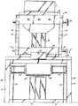
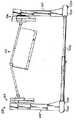
[0082] 図15−図17を参照すると、画像化部分100、100´が図示され
ており、図1−図12に開示された実施の形態のフレーム部分12、14に置換する。図
15−図17の各々は、部分100、100´が実質的に面一の形態に維持されるようケ
ーブル駆動体18が緊張状態とされる形態を示す。図15には、コラム3が上方に伸縮動
作し、フレーム部分が支持組立体5、6にてヒンジ止めし、その結果、患者の支持体の全
体が傾斜位置又は形態となる1つの形態が示されている。図示した実施の形態において、
部分100は患者の頭部を受け入れることが好ましい。このため、図15には、逆トレン
デンブルグ位置又は向きが示されている。図16には、再度、実質的に共通の面内にある
部分100、100´が示されており、双方の部分は、サブ組立体26を動力回転させる
ことにより、また、組立体26´を受動的に回転させることにより形成された傾動位置ま
で回転し、双方のコラム3、4は、さもなければ、部分100、100´を同一の高さに
保持する。図17には、組立体26、26´の回転に起因する傾動と、コラム4が垂直に
伸びた傾斜位置又は傾動位置との双方が示されている。このように、図17には、部分1
00、100´の双方が実質的に同一平面内に止まるトレンデレンブルグ位置又は向きが
示されている。台の一端又は双方における支承ブロック組立体は、ヒンジ機構の食い込み
を防止する多少の側方向並行移動を可能にすることが考えられる。[0082] Referring to FIGS. 15-17, the
Trendelenburg positions or orientations are shown where both 00 and 100 'remain substantially in the same plane. It is conceivable that the support block assembly at one or both sides of the platform allows some lateral translation to prevent the hinge mechanism from biting.
[0083] 図18−図20を参照すると、構造体1の3つの上方折れ又はヒンジ止
め形態が示されている。図18には、コラム3、4がそれぞれの支持組立体5、6を実質
的に同一の高さにて保持し、ケーブル20がウィンチモータの回転によって短縮され、そ
の結果、ヒンジ組立体16にて上方に折れ又は接続する、対称の上方折れ形態が示されて
いる。図19には、コラム3が最大高さまで伸び、ケーブルがリール巻きされて部分10
0、100´の間の距離を短縮する状態が示されている。逆トレンデレンブルグを有する
かかる上方折れ部すなわち継手の一例は、頭部又はコラム3の高さが109.22cm(
43インチ)、足部又はコラム4の高さが60.96cm(24インチ)であり、ロール
が零のとき、上方折れは35°である。図20には、コラム4が最大高さまで伸びた上方
折れのトレンデレンブルグが示されている。[0083] Referring to FIGS. 18-20, three upward fold or hinged configurations of the
A state in which the distance between 0 and 100 'is shortened is shown. An example of such an upward fold or joint having a reverse Trendelenburg has a head or
43 inches), the height of the foot or
[0084] 図21−図23を参照すると、構造体1の3つの下方折れ形態が示され
ている。図21には、コラム3、4が支持組立体5、6をそれぞれ同一の高さに保持し、
ケーブル20が巻き戻され又は弛緩してヒンジ組立体16にて下方折れ部すなわち継手と
なり、ヒンジ70、72がケーブル20と接触する対称の下方折れ形態が示されている。
図22には、コラム3が最大高さまで伸びて、その結果、患者の頭端部が最大高さとなる
下方折れの逆トレンデレンブルグが示されている。図23には、コラム4が最大高さまで
伸びた下方折れのトレンデレンブルグが示されている。[0084] Referring to FIGS. 21-23, three downward folding configurations of the
A symmetrical downward fold configuration is shown in which the
FIG. 22 shows a reverse-folded Trendelenburg in which the
[0085] 図18−図23に示した形態の各々にて、サブ組立体26は、両方向に
回転させることができ、その結果、傾動し又は回転するのみならず、上方又は下方に折れ
又はヒンジ止めした形態となることが理解される。例えば、図24には、支持フレーム部
分12、14が図19に示したものと同様であるが、回転を含む形態に配置され、その結
果、構造体1の傾動し且つ上方に折れ又は接続された形態となる構造体1が示されている
。図24に示した位置の一例は、頭部又はコラム3の高さが104cm(41インチ)、
足部又はコラム4の高さが86.4cm(34インチ)、10°ロール時の上方折れ又は
継手が35°である。[0085] In each of the configurations shown in FIGS. 18-23, the sub-assembly 26 can be rotated in both directions so that it not only tilts or rotates, but also folds or hinges upward or downward. It is understood that it will be in a stopped form. For example, in FIG. 24, the
The foot or
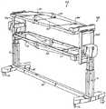
[0086] 図25−29を参照すると、本発明に従った別の構造体が全体として参
照番号102で示されている。構造体102は、構造体1に関し本明細書で説明した要素
の全てを利用し、このため、同一の要素又は特徴部には同一の参照番号が使用されている
。構造体102は、Hバーポスト40、40´が置換され又は改変されて、伸びたHバー
ポスト40A、40A´となり、2つの細長い構造体10及び協働するケーブル駆動体1
8を取り付けることを許容する点にて構造体1と相違する。図25に示した実施の形態に
おいて、構造体10の1つは、フレーム部材12、14を含む一方、他方の構造体は、部
分100、100´を有する画像化トップである。本明細書にて上述したように、複数の
開口が設けられた協働するHバーポスト40A、40A´は、支持構造体10を多岐にわ
たる位置に配置することを許容する。例えば、図25−28には、細長い画像化トップに
対する細長いフレームの第一の隔てた向きが示され、画像化トップは、参照符号Lで識別
した「下方」位置に配置されている。同一の構成要素は、図29に示されており、画像化
トップは、参照符号Mで識別した「中間位置」に配置されており、図25に示した細長い
画像化トップに対する細長いフレームのより小型であり、又は接近して隔てられた向きを
示す。[0086] Referring to FIGS. 25-29, another structure in accordance with the present invention is indicated generally by the
The
[0087] 図25−28に示したように、構造体102は、コントローラ29を使
用して回転サブ組立体26のモータを作動させることにより、患者の完全な回転、従って
、寝返りを可能にする。図25−29に示した構造体102は、コラム3、4の各々に固
定された非伸縮式の基部支持体110と、構造体102の基部におけるローラ又はキャス
タ112とを有して更に示されている。[0087] As shown in FIGS. 25-28, the
[0088] 図30及び図31を参照すると、本発明に従った別の実施の形態又はシ
ステムが全体として参照番号200で示されている。システム200は、広く、全体とし
て参照番号205、206で示したそれぞれの第一及び第二の支持組立体と接続されたそ
れぞれの第一及び第二の直立の支持ピア又はコラム203、204により各端部の上にあ
る細長い長さ調節可能な基部202を含む。それらの間にて、支持組立体205、206
は、全体として参照番号210で示した、細長い折れ、ヒンジ止め可能又は回動可能な患
者支持構造体を保持している。ヒンジ構造体は、その双方の開示内容を参考として引用し
本明細書に含めた、当該出願人の米国特許番号7,152,261及び米国特許出願番号
11/159,494に詳細に記載されている。図31に示した実施の形態200Aは、
長さ調節可能な基部202がピア203に装着された第一の基部220及びピア204に
装着された第二の基部222により置換される点においてのみ構造体200と相違する。
基部202、220、222の全ては、キャスタ又はローラ230又は何らかのその他の
可動構造体を含み、構造体210が上方に又は下方に折れする間、ピア203、204が
互いに向けて且つ互いに離れるように動くことを許容する。[0088] Referring to FIGS. 30 and 31, another embodiment or system in accordance with the present invention is indicated generally by the reference numeral 200. The system 200 is generally represented by respective first and second upright support peers or columns 203,204 connected to respective first and second support assemblies, generally indicated by reference numerals 205,206. An elongated length
Holds an elongated foldable, hingeable or pivotable patient support structure, generally designated by
It differs from the structure 200 only in that the length
All of the
[0089] 本明細書に記載したケーブル駆動体、ねじ駆動体を含むその他の型式の
モータ駆動体、自在継手、液圧システム及び同様のものを利用して、支持構造体210の
上方及び下方への折れの双方を容易にすることが考えられる。[0089] Up and down the
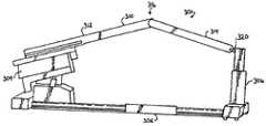
[0090] 本発明に従った別の患者支持構造体は、図32−34に全体として参照
番号301で示されている。構造体301は、全体として、水平方向に伸縮可能な、床に
取り付けた基部302と、従来の又は標準的な伸縮式で且つ傾動可能な手術台支持構造体
304と、伸縮可能な端部支持体又はピア306と、構造体304及びピア306の双方
と接続されたヒンジ止めし又は回動可能な上方及び下方折れ又は接続支持構造体310と
を含む。患者支持構造体310は、第一の片持ち式部分312と、第二の部分314とを
更に含む。第一の部分312は、手術台の支持体304に固定され且つ支持体304から
伸びている。第二の部分は、ヒンジにより、又は構造体1に関して本明細書にて説明した
支持組立体5のような、回動組立体320によりピア306に装着されている。支持部分
312、314の間に配設されたヒンジ機構316は、本明細書にて上述した従来のヒン
ジ、ピボット、又はピボット又はヒンジシステムとすることができる。[0090] Another patient support structure according to the present invention is indicated generally by the reference numeral 301 in FIGS. 32-34. The structure 301 generally includes a floor-mounted
[0091] 使用時、手術台の支持体304は、当該技術にて既知であるように、電
気又はその他の動力手段を利用して、支持部分312を上方及び下方に且つある傾斜角度
にて動かす。手術台の支持体304は、側方向に傾動し又は回転することもできる。部分
312の動きに応答して、部分314も動き、その結果、図32及び図33に示した上方
及び下方へ折れ状態となる。部分312の動きに応答して、電動の伸縮式基部302は、
ピア306を支持体304に向けて又は支持体304から離れるように動かす。ピア30
6は、接続部320にてピアを持ち上げ又は下降させるモータを含む。[0091] In use, the
The
6 includes a motor that lifts or lowers the peer at
[0092] 本明細書に記載した本発明のその他の実施の形態に関して上記に説明し
たように、本明細書に記載したケーブル駆動体、ねじ駆動体を含むその他の型式の駆動体
、液圧システム及び同様のものを利用して継手316にて支持構造体310の上方及び下
方への折れの双方を容易にすることができると考えられる。[0092] As described above with respect to the other embodiments of the invention described herein, other types of drivers, hydraulic systems, including cable drivers and screw drivers described herein. It is believed that the
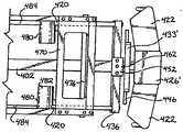
[0093] 図35−47を参照すると、全体として参照番号401で示した本発明
に従った別の患者支持構造体は、非伸縮式の基部支持体402により互いに接続された第
一及び第二の直立の支持ピア又はコラム403、404を含む。本発明に従った幾つかの
実施の形態において、コラムの各々は、独立的な可動の又は静止した基部上にあるように
することができる。コラム403は、全体として参照番号405で示した第一の支持組立
体と接続され、また、コラム404は、全体として参照番号406で示した第二の支持組
立体と接続されている。その両者の間にて、支持組立体405、406は、全体として参
照番号410で示した、少なくとも1つの除去可能な細長く且つ関節動作する、実質的に
中央にて接続され又は折れする患者の保持又は支持構造体を保持する。組立体は、第一の
フレーム部分412と、第二のフレーム部分414と、第一のフレーム部分412と第二
のフレーム部分414との間に配設され且つ第一のフレーム部分及び第二のフレーム部分
を接続する、全体として参照番号416で示した、1対の同一のヒンジ組立体とを含む。
図示した実施の形態において、患者の頭部及び上半身を保持する第一のフレーム部分41
2は、第二のフレーム部分414よりも僅かに短い長手方向長さ(軸線Xに沿った)のも
のである。このため、隔てられたヒンジ組立体416は、構造体410上に配置される患
者の身体に対してほぼ中央に配置される。図示した実施の形態において、ヒンジ組立体は
、全体として参照番号418で示したプルロッド組立体と、協働する隔てたスライダバー
420とを含む駆動システムを備えている。この場合にも、その他の駆動システムとする
ことが考えられる。[0093] Referring to FIGS. 35-47, another patient support structure according to the present invention, indicated generally by the
In the illustrated embodiment, a first frame portion 41 that holds the patient's head and upper body.
2 is of a longitudinal length (along the axis X) slightly shorter than the
[0094] コラム403、404は、構造体1に関して上記に説明したコラム3、
4と形態及び機能の点にて実質的に同様である。コラム403、404は、キャスタを含
む外方に伸びる足部422により支持されており、キャスタには、足部422を床係合位
置まで下降させる床−ロック足操作レバーが設けられている。コラム403、404は、
各々、2つ又はより多くの伸縮式リフトアームセグメントをそれぞれ含み、これらのリフ
トアームセグメントは、コラム403、404の各々の高さを選択的に加減して接続され
た患者の支持組立体410の全て又は選んだ部分を上昇し且つ下降させることを許容する
。[0094]
4 is substantially the same in terms of form and function. The
Each includes two or more telescopic lift arm segments that are connected to the patient support assembly 410 connected to selectively adjust the height of each of the
[0095] 支持組立体405、406の各々は、全体として、回転サブ組立体42
6、426´と、角度サブ組立体427、427´とをそれぞれ含み、これらのサブ組立
体は、構造体1に関して本明細書にて上記に説明したサブ組立体26、26´、27、2
7´と同一であり又は実質的に同様である。図示した実施の形態において、患者の頭部及
び上半身を保持するためフレーム412と接続された角度サブ組立体427は、サブ組立
体27と実質的に同一として示されており、このため、本明細書にて更に説明しない。サ
ブ組立体427´は、サブ組立体27´と実質的に同様であるが、構造体401の全体的
な長手方向軸線Xに対し横方向に配設されたフレーム436を有し、該フレーム436は
、フレーム414の両側部にて且つサブ組立体427´付近に配設された対の同一のスラ
イダバー420の摺動可能な支持体を提供することを含む、幾つかの改変例を有する。[0095] Each of the
6, 426 ′ and
The same as or substantially the same as 7 ′. In the illustrated embodiment, the
[0096] 本明細書にて上記に説明した回転サブ組立体26と同様に、回転サブ組
立体又は機構426は、支持コラム403の上にある少なくとも1つのモータハウジング
430を含む。協働するモータを支持コラム404に取り付けることも考えられる。主回
転軸432が回転構造体又はバーを回転させるモータハウジング430から伸びる一方、
回転構造体又はバーは、患者の支持体410と接続され且つ患者の支持体410を長手方
向軸線の回りにて回転させる。特に、モータハウジング430は、軸432と駆動可能に
係合した回転電気モータ又はその他のアクチュエータを収容している。回転機構426は
、スイッチ又はその他の同様の手段を使用してモータを起動させることにより作動させる
。軸432は、対の実質的に垂直に配設された並行移動ポスト又はHバーポスト440と
回転可能に協働し、ポスト440は、横方向回転構造体又はバー433に装着され且つそ
の両端に配設されている。Hバーポスト440の各々は、複数の開口444を含み、Hバ
ーポスト40に関して上記に説明したものと同一又は実質的に同様のフレーム部分412
、構造体1に関して上記に説明した角度サブ組立体27及びフレーム部分12のフレーム
端部分58を選択的にヒンジ止め式に垂直に配置することを許容する。[0096] Similar to the rotating
The rotating structure or bar is connected to the patient support 410 and rotates the patient support 410 about the longitudinal axis. In particular, the
, Allowing the
[0097] 上述したように、特に、図38−40を参照すると、サブ組立体426
´は、サブ組立体426と実質的に同様であり、このため、モータを含むことができ、ま
た、対の実質的に垂直に配設されたHバーポスト440´に装着された回転構造体又はバ
ー433´と係合するアクティブ又はパッセィブな回転軸432´の何れかを更に含む。
ポスト440´に形成された複数の協働する開口444´は、ピボットピン446が貫通
して伸びるための通路を提供する。ピボットピン446は、協働する対の開口444´の
各々に受け入れて、対のポスト440´の間に受け入れられ、また、ピボットピン446
を受け入れ得るような寸法及び形状とされた並行移動コネクタ448を選択的に配置する
ことを許容する。このように、ピン446及びコネクタ448は、外科医により選ぶこと
ができ、また、必要であれば、フレーム部分414の高さを変化させるべく、外科手術の
間でさえも容易に変更可能である、多岐にわたる高さにて患者の支持フレーム410の長
手方向軸線Xに対して横方向の向きにて位置決め可能である。例えば、図25−29に示
した実施の形態にて示したように、フレーム及び画像化台の双方が共に使用されるとき、
1つ以上のフレーム又はフレーム構造体がタンデムに取り付けられる場合、多数位置又は
高さの特徴は有益である。フレーム又はその他の構造体の位置は、患者の体格又はその他
の特徴、外科的及びその他の条件に依存して拡張可能又は縮小可能である、患者の支持体
と画像化トップとの間の距離にて、画像化トップへの近接性を提供し得るよう望ましいよ
うに変更することもできる。コネクタ448は、ピボットピン446を受け入れるスロッ
トを有している。Hバー支持体440´、開口444´、細長い横方向ピン446及び並
行移動コネクタ448は、構造体1に関して上記に説明したそれぞれの支持体40、開口
44、横方向ピン46及び並行移動コネクタ48と形態及び機能の点にて同一か又は実質
的に同様であることが理解される。[0097] As noted above, with particular reference to FIGS. 38-40,
'Is substantially similar to the sub-assembly 426, and thus can include a motor and a rotating structure mounted on a pair of substantially vertically disposed H-bar posts 440'. Alternatively, it further includes either an active or passive axis of rotation 432 'that engages the bar 433'.
A plurality of cooperating openings 444 'formed in the post 440' provide a passage for the
Allows the selective placement of
Multiple position or height features are beneficial when more than one frame or frame structure is attached in tandem. The position of the frame or other structure is at a distance between the patient support and the imaging top that can be expanded or contracted depending on the patient's physique or other characteristics, surgical and other conditions. And may be modified as desired to provide proximity to the imaging top.
[0098] 一方、ピボットコネクタ452が患者の支持フレーム414の端部ピー
ス又は部分に直接、装着されるではなくて、フレーム436に固定され、該フレーム43
6は、その端面464付近にて、スライダバー420に固定され且つスライダバー420
を支持する点を除いて、並行移動コネクタ448は、本明細書にて上記に説明したピボッ
トコネクタ52と実質的に同様である。このように、スライダバー420は、Hバー支持
体440´とヒンジ止めされた関係にある。スライダバー420は、また、以下に更に詳
細に説明するように、フレーム部分414に対して摺動可能に装着され且つ、部分414
の長手方向軸線に対して実質的に平行に配設されている。かかる摺動可能な装着は、部分
414がヒンジ機構416にて部分412に対して上方及び下方に折れ又はヒンジ止めす
るのを容易にする。以下に更に詳細に説明するように、フレーム部分414及びヒンジ機
構416の双方と接続されたプルロッド組立体418は、伸長可能で且つ後退可能であり
、患者の支持体410のヒンジ又は折れ角度を制御し、また、支持体410をヒンジ機構
416の所望の上方又は下方折れ部すなわち継手にて剛性であるようにする。[0098] On the other hand, the
6 is fixed to the
The
Are disposed substantially parallel to the longitudinal axis of the. Such slidable attachment facilitates folding or hinged
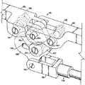
[0099] 図38及び図39を特に参照すると、支持フレーム部分414は、横方
向端部フレーム部分469により互いに装着された対向した細長で且つ平行なフレーム部
分466、468を含む。支持板470は、部分466、468、469の各々に装着さ
れ且つそれらの下方に配設されて、端部分469にて且つその付近にてフレーム部分41
4に追加的な支持作用及び安定性を提供する。更なる支持作用は、1対のフレーム支持板
471により提供され、そのフレーム支持板の双方は、その一端付近にて端部支持フレー
ム部分469に固定されている。1つの板471は、部分466に固定され、他方の板4
71は、部分468に固定される。少なくとも1対のスライドバーの保持構造体472は
、支持板470に固定され且つ、フレーム部分466、468の各々にて支持板から下方
に伸びている。構造体472の各々は、フレーム部分466、468及び構造体472に
対し平行に伸びる貫通穴を含み、フレーム部分466、468の一方の真下にてスライダ
バー420の1つを摺動可能に受け入れ且つ、対のスライダバー420をフレーム部分4
66、468に対し実質的に平行な方向にも向き決めする。図示したスライダバー保持構
造体472は、端部フレーム部分469から隔てられ且つ板470の前縁473近くに配
置されている。図示した実施の形態において、保持構造体472は、フレーム部分466
、468にもボルト止めされている。1対のプルロッド支持体475は、支持板470及
びフレーム414に固定され且つ、フレーム部分466、468の各々にてフレーム41
4から下方に、また、端部フレーム部分469から下方にも伸びている。構造体475の
各々は、スライダバー420の下方に取り付けられた横ピボットピン又はバー476を受
け入れる貫通穴を含む。プルロッド組立体418は、ピボットピン476にて支持体47
5に装着され、従って、端部分478にて回動可能に装着された支持体475とヒンジ止
めした関係にある。[0099] With particular reference to FIGS. 38 and 39, the
4 provides additional support and stability. Further support is provided by a pair of
71 is fixed to the portion 468. At least one pair of slide
The direction is also substantially parallel to 66 and 468. The illustrated slider
468 is also bolted. A pair of pull rod supports 475 are secured to the
4 extends downward, and also extends downward from the
5 and is therefore hinged to a
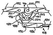
[0100] プルロッド組立体418は、1対のハウジング480を更に含み、ハウ
ジングの各々は、一端部分478に装着され且つ、1対の回転可能に伸び可能、後退可能
なロッド484と協働し且つ1対のヒンジコネクタ486と協働する動力式アクチュエー
タ482を有しており、また、該ヒンジコネクタの各々は、それぞれのピボットピン49
0にてそれぞれのヒンジ機構416のそれぞれのカム板488に回動可能に装着されてい
る。カム板488は、以下に詳細に説明するように、湾曲した開口又はスロットを形成す
る実質的に中央に配置された片持ち式壁489と、ピン490を受け入れる下方の円形開
口と、ピン502を受け入れる上方の円形の開口とを有している。プルロッド484の各
々は、ハウジング480の1つ内にて回転可能に取り付けられ、回転は、ハウジング48
0内に配置され且つロッド484と係合したアクチュエータ482の作動により制御され
、ロッド484をロッド484の長手方向軸線に沿った方向に向けてヒンジ機構416に
入り又はヒンジ機構から離れるよう選択的に動かし又は引き込み、その結果、患者の支持
体410は、ヒンジ機構416にて折れ又は接続される。本発明に従ったその他の実施の
形態は、例えば、液圧システムを含む、その他の型式のプッシュ/プルロッド又は機構を
利用することが考えられる。更なる支持作用を提供するため、中央に配置された追加的な
プルロッド又はピストンを含めることができる。更に、例えば、多軸継手、スポークを有
するローラ、スプロケット、歯付き歯車、自在軸線歯車、又は同様のものを含むが、これ
らにのみ限定されない、本発明に従ったその他の機構を機構416に代えて利用すること
ができる。[0100] The
At 0, each
Controlled by actuation of an
[0101] 特に、図41を参照すると、各々がカム板488を有する図示した対の
ヒンジ機構416は、フレーム部分412から伸びる1対のフォーク状アーム492と、
部分414に装着され且つ部分414から伸びる1対の協働するフォーク状アーム494
とを更に含む。ピボットピンを受け入れ得るように、その両端付近にて開口を有するヒン
ジアーム496、497、498、499は、ピボットピン501、502、503、5
04にてそれぞれのカム板488と、隣接するフォーク状アーム492、494と協働す
る。ピボットピン490、501、502、503、504の全ては、患者支持構造体4
01の長手方向軸線Xに対し横方向に配設されている。特に、ピボットピン501は、ヒ
ンジアーム496、498の第一の端部付近に配置された円形の開口と、アーム492の
円形の開口とに受け入れられ、このため、アーム492をヒンジアーム496、498の
双方にて回動可能に装着する。ピボットピン502は、カム板488の上方円形開口と、
フォーク状アーム492、494の各々の端部付近に配置された円形の開口とに受け入れ
られ、これにより、カム板488をフォーク状アーム492、494の双方に回動可能に
装着する。ピボットピン503は、ヒンジアーム497、499の第一の端部付近に配置
された円形の開口と、アーム494の円形の開口とに受け入れられ、このため、アーム4
94をヒンジアーム497、499の双方に回動可能に装着する。ピボットピン504は
、スロット489と、ヒンジアーム496、497、498、499の第二の端部付近に
配置された円形の開口とに受け入れられ、このため、カム板488と共に4つのヒンジア
ーム496、497、498、499の全てをスロット489にて回動可能に装着する。[0101] Referring specifically to FIG. 41, the illustrated pair of
A pair of cooperating forked
And. The
At 04, each
It is arranged transversely to the longitudinal axis X of 01. In particular,
The
94 is rotatably mounted on both hinge
[0102] また、特に、図35及び図38−図41を参照すると、構造体401は
、中立の平面状の向きにて示され、プル−ロッド組立体418は、ヒンジ機構416をか
かる中立位置に保持し、フォーク状アーム492、494は、平行である。かかる位置に
あるとき、ピン504は、スロット489の後端又はその付近に配置されている。[0102] Also, with particular reference to FIGS. 35 and 38-41, the
[0103] 図42−図44を参照すると、ロッド484が回転してロッド484を
選択的に長くするとき、ピン504は、スロット489の後端付近に止まり、ロッドをヒ
ンジ機構416に向けて押したとき、ピボットピン490にてカム板488は回動し、ア
ーム492、494をロッドヒンジコネクタ486に向けて動かし、従って、患者の支持
体をピン502にて回動させ、患者の支持体410に下方折れ部すなわち継手を生じさせ
る。図45−図47を参照すると、ロッド484が回転してその長さを選択的に短くした
とき、支持部分414は、スライダバー420に沿って摺動して端部支持体404から離
れる。これと同時に、カム板がピン490の回りにて前方向に回動したとき、ピン504
は、スロット489に沿って摺動し、その他端すなわち前端に達する。このように、ロッ
ド484の動きは、ピボットピン502にて上方折れ部を生じさせる。図示した実施の形
態において、患者のフレームは、頭端部にてピン止めされているが、足端部にて固定のス
ライダバー420に沿って自在に動くことができ、患者のフレームに対し動的支持作用を
提供する。スライダバー機構は、支承ブロック機構に装着して、上述したように、側方向
への並行移動を提供することができる。[0103] Referring to FIGS. 42-44, when the
Slides along
[0104] 患者のフレームは、スライダバーを超えて動くことが自由であるから、
患者の支持体の組み合わさった成分により水平方向力成分が生成されることが分かる。支
持体が上方に折れ又は接続されたとき、足端部フレームの角度はスライダに水平方向力を
加え、この力によって、端部支持体403、404は互いに向けて押される。台が下方に
折れたとき、端部支持体を押して分離させる傾向となる水平方向力が生成される。水平方
向力の大きさは、支持体の荷重及び折れ角度の関数であり、このため、例えば、患者の支
持体に対して226.796kg(500ポンド)の作用限界値が選ばれた場合、水平方
向荷重の最悪のケースは、35°の上方折れ部すなわち継手にて約26.308kg(5
8ポンド)にしか過ぎない。図示した構造体401は、約35°から約20°までの折れ
又は接続範囲を望ましいように支持することが分かる。かかる範囲の全体にわたって、構
造体により与えられる水平方向力は、スライダバーを支持体の足端部にて動かす図示した
係止された支持フレームにより最小とされる。[0104] Because the patient's frame is free to move beyond the slider bar,
It can be seen that a horizontal force component is generated by the combined components of the patient support. When the support is folded or connected upward, the angle of the foot end frame applies a horizontal force to the slider, which pushes the end supports 403, 404 towards each other. When the pedestal is folded downward, a horizontal force is generated that tends to push and separate the end supports. The magnitude of the horizontal force is a function of the support load and fold angle so that, for example, if an action limit of 226.796 kg (500 pounds) is selected for the patient support, The worst case of directional load is about 26.308 kg (5
Only 8 pounds). It can be seen that the illustrated
[0105] 図18−図23に示した構造体1の形態と同様に、患者の支持体410
の上方及び下方折れ部は、部分412、414をHバー支持体440、440´に沿った
異なる垂直位置に配置することにより変更し、その結果、対称の又は非対称の折れ形態と
なるようにすることができる。更に、部分412、414は、構造体1に関して上記に説
明したように、回転させ又は傾動させることができる。
[0106] 本発明の特定の形態について本明細書にて図示し且つ説明したが、これは
、説明し且つ図示した特定の形態又は配置にのみ限定されるものではないことを理解すべ
きである。[0105] The patient support 410, similar to the configuration of the
The upper and lower folds are modified by placing the
[0106] While particular forms of the invention have been illustrated and described herein, it should be understood that this is not intended to be limited only to the specific forms or arrangements described and illustrated. .
Claims (17)
Translated fromJapanesea)頭端部分と、足端部分と、前記頭端部分と前記足端部分の略中央に配置された継手
とを有し、前記頭端部分及び前記足端部分は前記継手にて回動可能に装着され、前記頭端
部分及び前記足端部分は、第一の平面内にて整合可能である細長い患者支持構造体と、
b)対向して隔てられた第一及び第二の端部支持体であって、前記第一の支持体は、前
記頭端部付近に配置され、前記第二の支持体は前記足端部付近に配置され、前記患者支持
構造体が前記第一及び第二の端部支持体の間を伸び且つ前記支持体により床に対して隔た
った関係に保持される第一及び第二の端部支持体と、
c)前記継手にて前記患者支持構造体と協働する少なくとも1つの接続構造体であって
、前記頭端部分及び前記足端部分を前記第一の平面内にて且つ前記第一の平面の両側部に
て互いに対して複数の角度の向きに選択的に動かし且つ係止する接続構造体とを備える、
患者を支持する装置。In a device that supports the patient while performing the medical method,
a) a head end portion, a foot end portion, and a joint disposed substantially at the center of the head end portion and the foot end portion, wherein the head end portion and the foot end portion are rotated by the joint; An elongated patient support structure that is detachably mounted and the head end portion and the foot end portion are alignable in a first plane;
b) first and second end supports spaced opposite each other, wherein the first support is disposed near the head end and the second support is the foot end. First and second ends disposed in proximity and wherein the patient support structure extends between the first and second end supports and is held in a spaced relation to the floor by the support. A support;
c) at least one connection structure cooperating with the patient support structure at the joint, wherein the head end portion and the foot end portion are in the first plane and in the first plane; A connecting structure that selectively moves and locks in a plurality of angular orientations relative to each other on both sides,
A device that supports the patient.
の支持体との間にて懸架される、装置。The apparatus of claim 1, wherein the patient support structure is suspended between the first support and the second support.
分又は前記足端部分の一方と片持ち式の関係にある、装置。The apparatus of claim 1, wherein one of the first and second end supports is in a cantilevered relationship with one of the head end portion or the foot end portion.
。The apparatus of claim 1, wherein the connection structure further comprises a hinge structure.
ルを受け入れる溝を有する、装置。6. The device according to claim 5, wherein the connection structure comprises a cable and has a groove for receiving the cable.
置。9. The device of claim 8, wherein the pull-rod is attached to the foot end portion.
部分の一方に摺動可能に装着された少なくとも1つのスライダバーを備え、前記スライダ
バーは前記端部支持体の一方に回動可能に装着される、装置。9. The apparatus of claim 8, wherein the connection structure further comprises at least one slider bar slidably mounted on one of the head end portion or the foot end portion, the slider bar being at the end. A device that is rotatably mounted on one of the support members.
能である、装置。The apparatus of claim 1, wherein at least one of the end supports is selectively extendable.
機構を備える、装置。The apparatus of claim 1, wherein at least one of the end supports further comprises a lateral displacement mechanism.
を備える、装置。The apparatus of claim 1, wherein at least one of the end supports further comprises a rotation mechanism.
第二の患者の支持体を備え、前記第二の患者の支持体は、画像化台である装置。The apparatus of claim 1, wherein the elongated patient support structure is a frame;
An apparatus comprising a second patient support, wherein the second patient support is an imaging platform.
の位置にて両端にて脱着可能且つ配置可能である、装置。The apparatus of claim 1, wherein the patient support structure is detachable and deployable at both ends at a plurality of positions vertically spaced from the floor.
a)第一及び第二の対向した端部支持体と、
b)前記第一及び第二の端部支持体に接続され且つ前記第一及び第二の端部支持体の間
を実質的に架橋する患者支持構造体であって、第一の部分と、第二の部分とを有し、前記
第一及び第二の部分は、前記支持構造体の長手方向軸線に沿って第一の実質的に平面状の
向きにて選択的に係止可能であり、前記第一及び第二の部分は、互いに対して複数の角度
にて配置可能で且つ係止可能であり、前記部分の各々は、前記第一の平面状の向きの両側
部の位置まで可動である、患者を支持する装置。In a device that supports the patient while performing the medical method,
a) first and second opposing end supports;
b) a patient support structure connected to the first and second end supports and substantially bridging between the first and second end supports, the first portion; A second portion, wherein the first and second portions are selectively lockable in a first substantially planar orientation along a longitudinal axis of the support structure. The first and second portions can be arranged and locked at a plurality of angles with respect to each other, and each of the portions is movable to positions on both sides of the first planar orientation. A device that supports the patient.
、装置。17. The device according to claim 16, wherein the first and second parts are attached by hinges.
Applications Claiming Priority (4)
| Application Number | Priority Date | Filing Date | Title |
|---|---|---|---|
| US79828806P | 2006-05-05 | 2006-05-05 | |
| US60/798,288 | 2006-05-05 | ||
| US11/788,513 | 2007-04-20 | ||
| US11/788,513US7565708B2 (en) | 2005-02-22 | 2007-04-20 | Patient positioning support structure |
Related Parent Applications (1)
| Application Number | Title | Priority Date | Filing Date |
|---|---|---|---|
| JP2012171886ADivisionJP2012236054A (en) | 2006-05-05 | 2012-08-02 | Patient positioning support structure |
Related Child Applications (1)
| Application Number | Title | Priority Date | Filing Date |
|---|---|---|---|
| JP2016041088ADivisionJP2016152923A (en) | 2006-05-05 | 2016-03-03 | Patient positioning support structure |
Publications (2)
| Publication Number | Publication Date |
|---|---|
| JP2014221400Atrue JP2014221400A (en) | 2014-11-27 |
| JP2014221400A5 JP2014221400A5 (en) | 2015-01-15 |
Family
ID=38668395
Family Applications (5)
| Application Number | Title | Priority Date | Filing Date |
|---|---|---|---|
| JP2009507857APendingJP2009534159A (en) | 2006-05-05 | 2007-05-07 | Patient positioning support structure |
| JP2012171886APendingJP2012236054A (en) | 2006-05-05 | 2012-08-02 | Patient positioning support structure |
| JP2014142074APendingJP2014221400A (en) | 2006-05-05 | 2014-07-10 | Patient positioning support structure |
| JP2016041088APendingJP2016152923A (en) | 2006-05-05 | 2016-03-03 | Patient positioning support structure |
| JP2017011315AActiveJP6327731B2 (en) | 2006-05-05 | 2017-01-25 | Patient positioning support structure |
Family Applications Before (2)
| Application Number | Title | Priority Date | Filing Date |
|---|---|---|---|
| JP2009507857APendingJP2009534159A (en) | 2006-05-05 | 2007-05-07 | Patient positioning support structure |
| JP2012171886APendingJP2012236054A (en) | 2006-05-05 | 2012-08-02 | Patient positioning support structure |
Family Applications After (2)
| Application Number | Title | Priority Date | Filing Date |
|---|---|---|---|
| JP2016041088APendingJP2016152923A (en) | 2006-05-05 | 2016-03-03 | Patient positioning support structure |
| JP2017011315AActiveJP6327731B2 (en) | 2006-05-05 | 2017-01-25 | Patient positioning support structure |
Country Status (7)
| Country | Link |
|---|---|
| US (26) | US7565708B2 (en) |
| EP (1) | EP2015725A4 (en) |
| JP (5) | JP2009534159A (en) |
| KR (1) | KR101279010B1 (en) |
| AU (3) | AU2007248426B2 (en) |
| CA (1) | CA2649350C (en) |
| WO (1) | WO2007130679A2 (en) |
Cited By (2)
| Publication number | Priority date | Publication date | Assignee | Title |
|---|---|---|---|---|
| KR20160096040A (en)* | 2015-02-04 | 2016-08-12 | 호엘 스티븐 | An adjustable support apparatus for a surgery table |
| KR20240156840A (en) | 2023-04-24 | 2024-10-31 | 서울대학교병원 | Joint Angle adjustment device for imaging |
Families Citing this family (153)
| Publication number | Priority date | Publication date | Assignee | Title |
|---|---|---|---|---|
| US20150059094A1 (en) | 2005-02-22 | 2015-03-05 | Roger P. Jackson | Patient positioning support structure |
| US7739762B2 (en) | 2007-10-22 | 2010-06-22 | Mizuho Orthopedic Systems, Inc. | Surgery table apparatus |
| US20130133137A1 (en)* | 2011-11-28 | 2013-05-30 | Roger P. Jackson | Patient positioning support structure with coordinated continuous nonsegmented articulation, rotation and lift, and locking fail-safe device |
| US9468576B2 (en) | 2005-02-22 | 2016-10-18 | Roger P. Jackson | Patient support apparatus with body slide position digitally coordinated with hinge angle |
| US9186291B2 (en)* | 2005-02-22 | 2015-11-17 | Roger P. Jackson | Patient positioning support structure with trunk translator |
| US9265679B2 (en) | 2005-02-22 | 2016-02-23 | Roger P Jackson | Cantilevered patient positioning support structure |
| US9295433B2 (en) | 2005-02-22 | 2016-03-29 | Roger P. Jackson | Synchronized patient elevation and positioning apparatus for use with patient positioning support systems |
| US9301897B2 (en) | 2005-02-22 | 2016-04-05 | Roger P. Jackson | Patient positioning support structure |
| US8844077B2 (en) | 2005-02-22 | 2014-09-30 | Roger P. Jackson | Syncronized patient elevation and positioning apparatus positioning support systems |
| US9744087B2 (en) | 2005-02-22 | 2017-08-29 | Roger P. Jackson | Patient support apparatus with body slide position digitally coordinated with hinge angle |
| US7565708B2 (en) | 2005-02-22 | 2009-07-28 | Jackson Roger P | Patient positioning support structure |
| US9308145B2 (en) | 2005-02-22 | 2016-04-12 | Roger P. Jackson | Patient positioning support structure |
| US8707484B2 (en)* | 2005-02-22 | 2014-04-29 | Roger P. Jackson | Patient positioning support structure |
| AU2006283126A1 (en)* | 2005-08-24 | 2007-03-01 | Thomson Licensing | Method for graphical scaling of LCDs in mobile television devices |
| US9642760B2 (en) | 2006-05-05 | 2017-05-09 | Roger P. Jackson | Patient positioning support apparatus with virtual pivot-shift pelvic pads, upper body stabilization and fail-safe table attachment mechanism |
| US10869798B2 (en)* | 2006-05-05 | 2020-12-22 | Warsaw Orthopedic, Inc. | Patient positioning support apparatus with virtual pivot-shift pelvic pads, upper body stabilization and fail-safe table attachment mechanism |
| US9339430B2 (en) | 2006-05-05 | 2016-05-17 | Roger P. Jackson | Patient positioning support apparatus with virtual pivot-shift pelvic pads, upper body stabilization and fail-safe table attachment mechanism |
| US8864205B2 (en) | 2006-06-28 | 2014-10-21 | Stryker Corporation | Patient support with wireless data and/or energy transfer |
| EP2046259B1 (en)* | 2006-06-28 | 2014-07-02 | Stryker Corporation | Patient support |
| CZ18426U1 (en)* | 2008-02-15 | 2008-04-07 | Linet, Spol. S R.O. | Bed positioning mechanism |
| KR100950162B1 (en)* | 2008-03-05 | 2010-03-30 | 유영선 | Body stretching bed |
| US8635725B2 (en)* | 2008-10-28 | 2014-01-28 | Tony Y. Tannoury | Prone and laterally angled surgical device and method |
| FR2940130B1 (en)* | 2008-12-19 | 2012-04-13 | Roussy Inst Gustave | PATIENT ORIENTATION AND CONTENT DEVICE FOR HADRONTHERAPY TREATMENT |
| US20100234771A1 (en)* | 2009-03-11 | 2010-09-16 | Patrick Ingrassia | Massage bench |
| US8707476B2 (en) | 2009-04-01 | 2014-04-29 | Operating Room Safety Enterprises, LLC | Apparatuses for posterior surgery |
| US8381331B2 (en) | 2009-04-01 | 2013-02-26 | Operating Room Safety Enterprises, LLC | Patient-rotation system with center-of-gravity assembly |
| US9211074B2 (en)* | 2009-06-09 | 2015-12-15 | Safeop Surgical, Inc. | System, method, apparatus, device and computer program product for automatically detecting positioning effect |
| IT1395114B1 (en)* | 2009-07-28 | 2012-09-05 | Itel Telecomunicazioni S R L | ROBOTIC SYSTEM FOR THE POSITIONING OF A PATIENT COMPARED TO AT LEAST ONE PARTICLE SOURCE |
| US8763178B1 (en)* | 2009-08-19 | 2014-07-01 | Martin Manufacturing Co., Llc | Low profile patient examination table |
| US9676497B2 (en)* | 2010-01-21 | 2017-06-13 | The Boeing Company | High rate pulsing wing assembly line |
| AU2015201454B2 (en)* | 2010-06-21 | 2018-03-29 | Warsaw Orthopedic, Inc. | Patient positioning support structure with trunk translator |
| USD663427S1 (en) | 2010-10-14 | 2012-07-10 | Operating Room Safety Enterprises, LLC | Torso-support apparatus |
| USD645967S1 (en)* | 2010-10-14 | 2011-09-27 | Patient Safety Transport Systems, Llc | Patient-support frame |
| WO2012061802A1 (en)* | 2010-11-05 | 2012-05-10 | Contour Fabricators, Inc. | Patient support system and support surface therefor and method of installation thereof |
| US9072646B2 (en)* | 2010-12-14 | 2015-07-07 | Allen Medical Systems, Inc. | Lateral surgical platform with rotation |
| US8584281B2 (en) | 2011-04-07 | 2013-11-19 | Mizuho Orthopedic Systems, Inc | Surgery table having coordinated motion |
| CN102853734A (en)* | 2011-06-30 | 2013-01-02 | 深圳富泰宏精密工业有限公司 | Support structure |
| GB201115391D0 (en)* | 2011-09-06 | 2011-10-19 | Wootton Malcolm | Operating tables and accessories |
| WO2013058806A1 (en) | 2011-10-17 | 2013-04-25 | Jackson Roger P | Patient positioning support structure |
| US9233043B2 (en)* | 2012-01-26 | 2016-01-12 | American Sterilizer Company | Femur support for a medical table |
| US9561145B2 (en)* | 2012-02-07 | 2017-02-07 | Roger P. Jackson | Fail-safe release mechanism for use with patient positioning support apparati |
| US9265680B2 (en)* | 2012-03-06 | 2016-02-23 | Operating Room Safety Enterprises, LLC | Surgical table |
| US9474671B2 (en)* | 2012-03-06 | 2016-10-25 | Operating Room Safety Enterprises, LLC | Surgical table |
| US9498397B2 (en) | 2012-04-16 | 2016-11-22 | Allen Medical Systems, Inc. | Dual column surgical support system |
| DE202012003941U1 (en)* | 2012-04-20 | 2012-07-23 | Igus Gmbh | Caddy for cable drag chains |
| JP6426083B2 (en) | 2012-05-02 | 2018-11-21 | セーフオプ サージカル インコーポレイテッド | Systems, methods, and computer algorithms for characterizing and classifying electrophysiological evoked potentials |
| US9597043B1 (en) | 2012-05-31 | 2017-03-21 | Dartmouth-Hitchcock Clinic | System and method for supporting a patient for imagery during surgery |
| CN104582661B (en) | 2012-08-18 | 2017-11-28 | 有限会社知财经营社 | Sleep Position Control Bed System |
| US20140081659A1 (en) | 2012-09-17 | 2014-03-20 | Depuy Orthopaedics, Inc. | Systems and methods for surgical and interventional planning, support, post-operative follow-up, and functional recovery tracking |
| ITMI20121548A1 (en) | 2012-09-18 | 2014-03-19 | Medacta Int Sa | APPARATUS FOR POSITIONING THE LOWER ARTH OF A PATIENT IN OPERATIVE OFFICE, IN PARTICULAR FOR REPLACEMENT OPERATIONS OF THE ANCHOR WITH A FRONT APPROACH, AND A SURGICAL POSITIONING SYSTEM INCLUDING THE APPLIANCE |
| ITMI20121546A1 (en) | 2012-09-18 | 2014-03-19 | Medacta Int Sa | ADAPTER FLOOR FOR SURGICAL TABLE, IN PARTICULAR FOR REPLACEMENT OPERATIONS OF THE HOOK WITH FRONT APPROACH |
| USD745971S1 (en) | 2013-03-06 | 2015-12-22 | Operating Room Safety Enterprises, LLC | Surgical table |
| USD720076S1 (en) | 2013-03-06 | 2014-12-23 | Operating Room Safety Enterprises, LLC | Surgical table |
| JP6345485B2 (en)* | 2013-05-29 | 2018-06-20 | キヤノンメディカルシステムズ株式会社 | Bed apparatus, X-ray CT apparatus, and medical image diagnostic apparatus |
| US12011399B2 (en)* | 2013-08-28 | 2024-06-18 | Warsaw Orthopedic, Inc. | Patient positioning support apparatus with fail-safe connector attachment mechanism |
| GB2518394A (en)* | 2013-09-20 | 2015-03-25 | Sherborne Upholstery Ltd | Adjustable bed |
| EP3065687B1 (en)* | 2013-11-06 | 2018-12-26 | IDEAssociates (IOM) Limited | A bed |
| US11083387B2 (en) | 2013-11-07 | 2021-08-10 | Safeop Surgical, Inc. | Systems and methods for detecting nerve function |
| EP2873405B1 (en)* | 2013-11-18 | 2016-05-18 | Schaerer Medical Management AG | Modular operating table |
| US10406068B2 (en) | 2014-02-19 | 2019-09-10 | Keith G. Lurie | Lockable head up cardiopulmonary resuscitation support device |
| US11844742B2 (en) | 2014-02-19 | 2023-12-19 | Keith G. Lurie | Methods and systems to reduce brain damage |
| US10667987B2 (en) | 2014-02-19 | 2020-06-02 | Keith G. Lurie | Uniform chest compression CPR |
| US9801782B2 (en) | 2014-02-19 | 2017-10-31 | Keith G. Lurie | Support devices for head up cardiopulmonary resuscitation |
| US10406069B2 (en) | 2014-02-19 | 2019-09-10 | Keith G. Lurie | Device for elevating the head and chest for treating low blood flow states |
| US9707152B2 (en) | 2014-02-19 | 2017-07-18 | Keith G. Lurie | Systems and methods for head up cardiopulmonary resuscitation |
| US11246794B2 (en) | 2014-02-19 | 2022-02-15 | Keith G. Lurie | Systems and methods for improved post-resuscitation recovery |
| US10350137B2 (en) | 2014-02-19 | 2019-07-16 | Keith G. Lurie | Elevation timing systems and methods for head up CPR |
| US10245209B2 (en) | 2014-02-19 | 2019-04-02 | Keith G. Lurie | Systems and methods for gravity-assisted cardiopulmonary resuscitation |
| US11020314B2 (en) | 2014-02-19 | 2021-06-01 | Keith G. Lurie | Methods and systems to reduce brain damage |
| US11259988B2 (en) | 2014-02-19 | 2022-03-01 | Keith G. Lurie | Active compression decompression and upper body elevation system |
| US12144777B2 (en) | 2014-02-19 | 2024-11-19 | Resuscitation Innovations Llc | Methods and systems to reduce brain damage |
| US9750661B2 (en) | 2014-02-19 | 2017-09-05 | Keith G. Lurie | Systems and methods for head up cardiopulmonary resuscitation |
| US11096861B2 (en) | 2014-02-19 | 2021-08-24 | Keith G. Lurie | Systems and methods for gravity-assisted cardiopulmonary resuscitation and defibrillation |
| EP2944259A1 (en)* | 2014-05-15 | 2015-11-18 | Buck Engineering & Consulting GmbH | Patient positioning device |
| US9549863B2 (en)* | 2014-07-07 | 2017-01-24 | Roger P. Jackson | Surgical table with pivoting and translating hinge |
| US9402775B2 (en)* | 2014-07-07 | 2016-08-02 | Roger P. Jackson | Single and dual column patient positioning and support structure |
| CN104546361B (en)* | 2014-12-29 | 2016-09-14 | 奚健 | Operating table for microspinal surgery |
| US10492973B2 (en) | 2015-01-05 | 2019-12-03 | Allen Medical Systems, Inc. | Dual modality prone spine patient support apparatuses |
| US9713562B2 (en)* | 2015-02-06 | 2017-07-25 | Mizuho Orthopedic Systems, Inc. | Surgery table attachment apparatus |
| US9700476B2 (en)* | 2015-02-06 | 2017-07-11 | Mizuho Orthopedic Systems, Inc. | Patient platform connection device |
| DE202015101357U1 (en)* | 2015-03-17 | 2016-06-22 | Hermann Bock Gmbh | Height adjustable bed |
| US9655793B2 (en) | 2015-04-09 | 2017-05-23 | Allen Medical Systems, Inc. | Brake release mechanism for surgical table |
| US11197640B2 (en) | 2015-05-04 | 2021-12-14 | Safeop Surgical, Inc. | System, method, and computer algorithm for measuring, displaying, and accurately detecting changes in electrophysiological evoked potentials |
| TWM507268U (en)* | 2015-05-20 | 2015-08-21 | Chun-Yen Li | Turnover device bracket |
| US11382816B2 (en) | 2015-06-05 | 2022-07-12 | Stryker Corporation | Surgical table and accessories to facilitate hip arthroscopy |
| JP6170522B2 (en)* | 2015-06-09 | 2017-07-26 | 矢島工業株式会社 | Position control device |
| US10426684B2 (en) | 2015-06-11 | 2019-10-01 | Allen Medical Systems, Inc. | Person support apparatuses including person repositioning assemblies |
| US10548796B2 (en) | 2015-08-17 | 2020-02-04 | Warsaw Orthopedic, Inc. | Surgical frame and method for use thereof facilitating articulatable support for a patient during surgery |
| AU2016308175B2 (en) | 2015-08-17 | 2021-04-01 | Warsaw Orthopedic, Inc. | Surgical frame facilitating articulatable support for a patient during surgery |
| US10561559B2 (en) | 2015-10-23 | 2020-02-18 | Allen Medical Systems, Inc. | Surgical patient support system and method for lateral-to-prone support of a patient during spine surgery |
| US10363189B2 (en) | 2015-10-23 | 2019-07-30 | Allen Medical Systems, Inc. | Surgical patient support for accommodating lateral-to-prone patient positioning |
| US10857054B2 (en) | 2015-11-13 | 2020-12-08 | Allen Medical Systems, Inc. | Person support apparatuses for subject repositioning |
| ES2572633B1 (en)* | 2016-01-16 | 2017-03-17 | Gerinet, S.L.U. | Bed with mobile frame |
| US10582981B2 (en) | 2016-02-02 | 2020-03-10 | Stryker Corporation | Accessory support and coupling systems for an accessory support |
| US10893988B2 (en) | 2016-05-26 | 2021-01-19 | Stryker Corporation | Patient support systems and methods for docking, transporting, sterilizing, and storing patient support decks |
| US11160709B2 (en) | 2016-06-14 | 2021-11-02 | Warsaw Orthopedic, Inc. | Surgical table with movement capabilities of lower body support structures |
| US10548793B2 (en)* | 2016-06-14 | 2020-02-04 | Allen Medical Systems, Inc. | Pinless loading for spine table |
| CN106361528B (en)* | 2016-08-25 | 2017-10-20 | 申桂广 | Neurosurgery spinal operation bracket system |
| US11986321B2 (en) | 2016-09-22 | 2024-05-21 | Safeop Surgical, Inc. | System and method for detecting and removing periodic non-physiological artifact from evoked potentials |
| US10881567B2 (en)* | 2016-10-28 | 2021-01-05 | Stryker Corporation | Patient support apparatus |
| US10188566B2 (en)* | 2016-10-31 | 2019-01-29 | Accora Limited | Lifting mechanism |
| US10744053B2 (en) | 2016-12-07 | 2020-08-18 | Stryker Corporation | Haptic systems and methods for a user interface of a patient support apparatus |
| US10342722B2 (en) | 2016-12-22 | 2019-07-09 | Benito J. GARRIDO | Surgical tables for spinal surgeries employing lordosis adjustment subassemblies rotatably connected to rigid frames, and related systems and methods |
| DE102016125800A1 (en)* | 2016-12-28 | 2018-06-28 | MAQUET GmbH | Operating table column with stabilization guide |
| US10849808B2 (en) | 2017-01-05 | 2020-12-01 | Allen Medical Systems, Inc. | Reconfigurable patient support device and patient support system |
| CA3052793A1 (en) | 2017-02-06 | 2018-08-09 | Stryker Corp. | Distraction frame for effecting hip distraction |
| EP3576687B1 (en) | 2017-02-06 | 2025-07-02 | Stryker Corporation | Method and apparatus for supporting and stabilizing a patient during hip distraction |
| US11510805B2 (en) | 2017-02-06 | 2022-11-29 | Stryker Corp. | Anatomical gripping system for gripping the leg and foot of a patient when effecting hip distraction and/or when effecting leg positioning |
| US10900448B2 (en) | 2017-03-10 | 2021-01-26 | Warsaw Orthopedic, Inc. | Reconfigurable surgical frame and method for use thereof |
| US11963775B2 (en) | 2017-03-22 | 2024-04-23 | Safeop Surgical, Inc. | Medical systems and methods for detecting changes in electrophysiological evoked potentials |
| CN106901935B (en)* | 2017-04-23 | 2018-12-18 | 诸暨市领跑管理咨询事务所 | A kind of hospital's shaping device easy to use |
| US10874570B2 (en)* | 2017-06-30 | 2020-12-29 | Warsaw Orthopedic, Inc. | Surgical frame and method for use thereof facilitating patient transfer |
| US10576006B2 (en) | 2017-06-30 | 2020-03-03 | Warsaw Orthopedic, Inc. | Surgical frame having translating lower beam and method for use thereof |
| US11213448B2 (en) | 2017-07-31 | 2022-01-04 | Allen Medical Systems, Inc. | Rotation lockout for surgical support |
| US11020304B2 (en) | 2017-08-08 | 2021-06-01 | Warsaw Orthopedic, Inc. | Surgical frame including main beam for facilitating patient access |
| USD878836S1 (en) | 2017-08-17 | 2020-03-24 | Stryker Corp. | Table extender |
| US11007102B2 (en) | 2017-08-22 | 2021-05-18 | Stryker Corporation | Patient transport system |
| DK179748B1 (en) | 2017-09-15 | 2019-05-01 | Bergmann Jean-Paul | Hospital bed with an enclosed housing, easy to clean and maintain |
| US11116680B2 (en) | 2017-09-19 | 2021-09-14 | Stryker Corporation | Patient support apparatus for controlling patient ingress and egress |
| US11052005B2 (en) | 2017-09-19 | 2021-07-06 | Stryker Corporation | Patient support apparatus with handles for patient ambulation |
| US11160705B2 (en) | 2017-10-20 | 2021-11-02 | Stryker Corporation | Adjustable patient support apparatus for assisted egress and ingress |
| US11039892B2 (en)* | 2017-12-22 | 2021-06-22 | Zimmer, Inc. | Robotically-assisted knee arthroplasty support systems and methods |
| US11202731B2 (en) | 2018-02-28 | 2021-12-21 | Allen Medical Systems, Inc. | Surgical patient support and methods thereof |
| US11510833B2 (en) | 2018-04-05 | 2022-11-29 | Taylor C. Kirkpatrick | Human body positioning system |
| CN108542678B (en)* | 2018-05-11 | 2024-02-23 | 石家庄高新区亿成科技有限公司 | Compensation device for operation bed board |
| CN108836721B (en)* | 2018-07-12 | 2020-04-07 | 王君 | Movable support for obstetrics and gynecology department |
| US10835439B2 (en)* | 2018-08-21 | 2020-11-17 | Warsaw Orthopedic, Inc. | Surgical frame having translating lower beam and moveable linkage or surgical equipment attached thereto and method for use thereof |
| US10893996B2 (en)* | 2018-08-22 | 2021-01-19 | Warsaw Orthopedic, Inc. | Surgical frame having translating lower beam and moveable linkage or surgical equipment attached thereto and method for use thereof |
| US11471354B2 (en) | 2018-08-30 | 2022-10-18 | Allen Medical Systems, Inc. | Patient support with selectable pivot |
| CN211797334U (en) | 2018-08-31 | 2020-10-30 | 希尔-罗姆服务公司 | Patient rotation system |
| CN109363876A (en)* | 2018-12-04 | 2019-02-22 | 王玉 | Gastroenterology inspection auxiliary frame |
| CN109330809A (en)* | 2018-12-13 | 2019-02-15 | 安方敬 | A kind of medical imaging auxiliary support apparatus |
| EP3705048B1 (en)* | 2019-03-04 | 2021-04-21 | Boscherini, Duccio | A surgical table with an integrated imaging device |
| DE102019203882B3 (en)* | 2019-03-21 | 2020-07-02 | Siemens Healthcare Gmbh | Patient positioning device and medical imaging device |
| US10881570B2 (en) | 2019-04-26 | 2021-01-05 | Warsaw Orthopedic, Inc | Reconfigurable pelvic support for a surgical frame and method for use thereof |
| US11497669B2 (en) | 2019-04-27 | 2022-11-15 | Ethicon, Inc. | Systems, devices, and methods for testing suture performance under static and dynamic conditions |
| US11234886B2 (en) | 2019-09-25 | 2022-02-01 | Warsaw Orthopedic, Inc. | Reconfigurable upper leg support for a surgical frame |
| CN110916924A (en)* | 2019-11-21 | 2020-03-27 | 中国人民解放军陆军军医大学第一附属医院 | Surgical nursing support device |
| CN111000635B (en)* | 2019-12-06 | 2020-09-18 | 河南省肿瘤医院 | Mechanical arm mechanism for tumor resection |
| EP4099971B1 (en) | 2020-02-03 | 2025-09-17 | Alphatec Spine, Inc. | Patient positioning system |
| US11304867B2 (en) | 2020-04-22 | 2022-04-19 | Warsaw Orthopedic, Inc. | Lift and method for use of a lift for positioning a patient relative to a surgical frame |
| US11813217B2 (en) | 2020-04-22 | 2023-11-14 | Warsaw Orthopedic, Inc | Lift and method for use of a lift for positioning a patient relative to a surgical frame |
| US11564855B2 (en) | 2020-09-28 | 2023-01-31 | Stryker Corporation | Systems and methods for supporting and stabilizing a patient during hip distraction |
| CN112353586B (en)* | 2020-09-30 | 2022-04-15 | 重庆顺美吉医疗器械有限公司 | Medical electric bed |
| CN113995615A (en)* | 2021-12-07 | 2022-02-01 | 中国人民解放军总医院第八医学中心 | Obstetric table for obstetrics and gynecology department |
| US20230190255A1 (en)* | 2021-12-22 | 2023-06-22 | Globus Medical, Inc. | Patient positioner |
| US11925586B2 (en) | 2022-03-25 | 2024-03-12 | Mazor Robotics Ltd. | Surgical platform and trolley assembly |
| US12207946B2 (en) | 2022-05-10 | 2025-01-28 | Warsaw Orthopedic, Inc. | Surgical platform system |
| US12150902B2 (en) | 2022-05-10 | 2024-11-26 | Warsaw Orthopedic, Inc. | Surgical table |
| US12213905B2 (en) | 2022-05-10 | 2025-02-04 | Warsaw Orthopedic, Inc. | Surgical platform system |
| US12239584B2 (en) | 2022-06-22 | 2025-03-04 | Warsaw Orthopedic, Inc. | Interface moveably interconnecting surgical table and gantry |
| US12011397B2 (en) | 2022-08-26 | 2024-06-18 | EMPLASE Medical Technologies, LLC | Patient-positioning system, computer-control and data-integration system, surgical componentry, and surgical methods of using same |
| US12396909B2 (en) | 2022-08-29 | 2025-08-26 | Warsaw Orthopedic, Inc. | Surgical platform system |
Citations (5)
| Publication number | Priority date | Publication date | Assignee | Title |
|---|---|---|---|---|
| US4391438A (en)* | 1981-06-12 | 1983-07-05 | Heffington Jr Charles A | Patient support attachment for surgical tables |
| JP2000116733A (en)* | 1998-10-09 | 2000-04-25 | Maquet Ag | Surgical operation table system |
| US6260220B1 (en)* | 1997-02-13 | 2001-07-17 | Orthopedic Systems, Inc. | Surgical table for lateral procedures |
| JP2002529115A (en)* | 1998-08-07 | 2002-09-10 | ヒル−ロム,インコーポレイティド | Stretchers for obstetrics and gynecology |
| US20040133983A1 (en)* | 2003-01-13 | 2004-07-15 | Newkirk David C. | Surgical table |
Family Cites Families (250)
| Publication number | Priority date | Publication date | Assignee | Title |
|---|---|---|---|---|
| US430635A (en) | 1890-06-24 | Invalid-bed | ||
| US392743A (en) | 1888-11-13 | millen | ||
| US377377A (en) | 1888-02-07 | Spring-bed | ||
| US769415A (en) | 1903-09-12 | 1904-09-06 | Jasper D Smock | Attachment for head-rests. |
| US1032743A (en) | 1909-11-15 | 1912-07-16 | Minneapolis Bedding Company | Hospital-bed. |
| US987423A (en) | 1910-04-01 | 1911-03-21 | Universal Bed And Hospital Supply Company | Adjustable reclining spring-frame. |
| US1046430A (en) | 1911-08-25 | 1912-12-10 | Henry C Beitz | Back-rest attachment for beds. |
| US1098477A (en) | 1913-04-11 | 1914-06-02 | Patrick Cashman | Apparatus for elevating and conveying invalids. |
| US1171713A (en)* | 1914-02-16 | 1916-02-15 | John K Gilkerson | Chiropractic table. |
| US1098209A (en) | 1914-02-19 | 1914-05-26 | David B Allen | Adjustable head and back rest for beds. |
| US1160451A (en) | 1914-04-06 | 1915-11-16 | Charles H Sanford | Combined fracture and orthopedic operating-table. |
| US1143618A (en) | 1914-09-12 | 1915-06-22 | Martin R Ewald | Bed attachment. |
| US1356467A (en) | 1919-02-04 | 1920-10-19 | Frederick R Payne | Invalid's bed |
| US1404482A (en) | 1920-05-11 | 1922-01-24 | Walter H Sawyer | Invalid bed |
| US1524399A (en) | 1921-01-07 | 1925-01-27 | Theodore H Krueger | Carrier for packages and the like |
| US1482439A (en) | 1922-02-17 | 1924-02-05 | William A Mccollough | Invalid's bed |
| US1528835A (en) | 1922-09-23 | 1925-03-10 | William A Mccollough | Invalid's bed |
| US1667982A (en) | 1925-06-04 | 1928-05-01 | Pearson Royal Washington | Revolving bed |
| US1799692A (en)* | 1925-08-08 | 1931-04-07 | St Louis Union Trust C Incorpo | Operating stand |
| US1780399A (en) | 1928-04-12 | 1930-11-04 | Edmund L Munson | Hospital bed |
| US1938006A (en)* | 1932-05-11 | 1933-12-05 | Edward P Blanchard | Manipulative table for spinal correction |
| US1990357A (en) | 1933-04-17 | 1935-02-05 | John W Speck | Invalid bed construction |
| US2188592A (en) | 1936-12-21 | 1940-01-30 | Damon R Hosken | Invalid bed |
| US2261297A (en)* | 1941-03-03 | 1941-11-04 | Seib Frederick Anthony | Hospital bed crane |
| GB569758A (en) | 1943-09-14 | 1945-06-07 | Hoskins & Sewell Ltd | Improvements relating to hospital beds |
| US2411768A (en) | 1944-09-02 | 1946-11-26 | Henry M Welch | Boxcar brace |
| US2475003A (en) | 1945-01-02 | 1949-07-05 | Lewis M Black | Body manipulation apparatus |
| US2688410A (en) | 1949-08-27 | 1954-09-07 | George B Nelson | Device for transporting bedridden patients |
| BE510346A (en)* | 1950-07-21 | |||
| US2792945A (en) | 1952-10-13 | 1957-05-21 | Stanley J Brenny | Corpse handling device |
| GB810956A (en) | 1956-04-13 | 1959-03-25 | Allen & Hanburys Ltd | Improvements relating to surgical operation tables |
| US3046071A (en) | 1958-07-24 | 1962-07-24 | Shampaine | Head-end control surgical operating table |
| US3049726A (en) | 1960-03-15 | 1962-08-21 | Clarence A Getz | Mobile body lift |
| US3281141A (en)* | 1963-01-15 | 1966-10-25 | American Sterilizer Co | Surgical table |
| US3302218A (en) | 1965-05-28 | 1967-02-07 | Stryker Corp | Turning frame |
| SE336195B (en)* | 1968-07-17 | 1971-06-28 | Jaernhs Elektriska Ab | |
| US3584321A (en)* | 1969-09-12 | 1971-06-15 | Donald L Buchanan | Hydraulic positioning bed for radioisotope scanning |
| US3640416A (en) | 1970-10-16 | 1972-02-08 | John J Temple | Reverse angle thread system for containers |
| US3766384A (en)* | 1971-04-28 | 1973-10-16 | Tower Co Inc | Surgical table |
| SU371359A1 (en) | 1971-06-15 | 1973-02-22 | В. И. Соколовский, В. П. Банков , В. С. Паршин Уральский политехнический институт С. М. Кирова | SCREW PAIR |
| US3827089A (en) | 1971-09-16 | 1974-08-06 | W Grow | Turnover bed assembly |
| US3832742A (en) | 1972-06-07 | 1974-09-03 | Stryker Corp | End support for anterior bed frame |
| US3814414A (en)* | 1972-07-24 | 1974-06-04 | H Chapa | Medical examination table |
| US3868103A (en) | 1973-04-24 | 1975-02-25 | Millet Roux & Cie Ltee | Surgical and examination table structure |
| JPS53763Y2 (en) | 1973-07-19 | 1978-01-11 | ||
| US3988790A (en) | 1973-11-29 | 1976-11-02 | Mracek Milo F | Portable support for a bed patient |
| US3937054A (en) | 1974-09-10 | 1976-02-10 | Armco Steel Corporation | Heavy duty pipe spreader |
| JPS53763A (en) | 1976-06-22 | 1978-01-06 | Riyouichi Enohayashi | Bed functioning as chair |
| GB1554115A (en)* | 1976-06-28 | 1979-10-17 | Ohio Nuclear | Patient support systems |
| JPS5320691A (en)* | 1976-08-10 | 1978-02-25 | Mizuho Ika Kougiyou Kk | Lowwvoltage dc powered separable electric operation table apparatus |
| US4144880A (en)* | 1977-03-11 | 1979-03-20 | Daniels E Robert | Orthopedic table |
| CH617344A5 (en)* | 1977-05-27 | 1980-05-30 | Schaerer Ag M | |
| CH615587A5 (en)* | 1977-05-27 | 1980-02-15 | Schaerer Ag M | |
| US4175550A (en)* | 1978-03-27 | 1979-11-27 | Leininger James R | Therapeutic bed |
| US4195829A (en) | 1978-04-21 | 1980-04-01 | Sybron Corporation | Surgical table hydraulic system |
| US4230100A (en) | 1978-07-26 | 1980-10-28 | Moon Derryl E | Chiropractic table |
| US4227269A (en)* | 1978-09-01 | 1980-10-14 | Burke, Inc. | Adjustable bed |
| US4292962A (en) | 1979-04-19 | 1981-10-06 | Krause Nicolaas J P R | Apparatus for postural treatment of humans |
| US4244358A (en) | 1979-09-10 | 1981-01-13 | Noel Pyers | Rollover bed having pallet with flex points and constant traction maintaining apparatus |
| US4384378A (en)* | 1980-10-17 | 1983-05-24 | Tri W-G, Inc. | Mobile body lift |
| US4763643A (en)* | 1981-01-19 | 1988-08-16 | Kinetic Concepts, Inc. | Arc changing apparatus for a therapeutic oscillating bed |
| US4872656A (en) | 1981-12-21 | 1989-10-10 | American Sterilizer Company | Orthopedic table with movable upper body and sacrum supports |
| US4989848A (en) | 1981-12-21 | 1991-02-05 | American Sterilizer Company | Apparatus for adjusting the position of the upper body support of an orthopedic table |
| US4435861A (en) | 1982-02-25 | 1984-03-13 | Lindley William L | Ledge bed |
| US4534076A (en)* | 1982-05-05 | 1985-08-13 | Barge Fred H | Reclining radiographic wall table |
| DE3218328A1 (en)* | 1982-05-14 | 1983-11-17 | Stierlen-Maquet Ag, 7550 Rastatt | OPERATING TABLE |
| US4474364A (en) | 1982-11-29 | 1984-10-02 | American Sterilizer Company | Surgical table |
| US4503844A (en)* | 1983-01-13 | 1985-03-12 | Fischer Imaging Corporation | Surgical table |
| JPS60172429A (en) | 1984-02-17 | 1985-09-05 | Aioi Seiki Kk | Side-bent chain system hydraulic cylinder driving type push-pull operating device for tool and the like of working machine |
| US4718077A (en) | 1985-03-14 | 1988-01-05 | Moore Robert R | Radiolucent table for medical radiography |
| IE58731B1 (en)* | 1986-05-02 | 1993-11-03 | Alliance Investments Ltd | A therapeutic bed |
| US4712781A (en)* | 1986-05-12 | 1987-12-15 | Watanabe Orthopedic Systems, Inc. | Operating table for microscopic lumbar laminectomy surgery |
| US4771785A (en) | 1986-07-25 | 1988-09-20 | Resonex, Inc. | Magnetic resonance imaging apparatus and three-axis patient positioning assembly for use therewith |
| US4715073A (en) | 1986-08-22 | 1987-12-29 | Butler Wilbur T | Tiltable bed frame assembly |
| US4872657A (en)* | 1986-10-17 | 1989-10-10 | M. Schaerer Ag | Operating table with a patient support surface tiltable around the longitudinal and transverse axes |
| US4944500A (en) | 1987-04-07 | 1990-07-31 | American Sterilizer Company | Translation lock for surgical table with displaceable tabletop |
| FR2621245B1 (en)* | 1987-10-05 | 1997-10-24 | Tasserit Ets | ORTHOPEDIC OPERATING TABLE FOR MEMBERS AND PARTICULARLY FOR LOWER MEMBERS |
| US4850775A (en) | 1988-04-26 | 1989-07-25 | Lee Jae B | Screw-type fastening device |
| US4862529A (en)* | 1988-07-13 | 1989-09-05 | Hill-Rom Company, Inc. | Hospital bed convertible to chair |
| US4937901A (en)* | 1988-11-04 | 1990-07-03 | Brennan Louis G | Apparatus for turning a patient from a supine to a prone position and vice-versa |
| US4939801A (en) | 1988-12-22 | 1990-07-10 | Schaal Gary A | Patient transporting and turning gurney |
| DE3902027C1 (en) | 1989-01-25 | 1990-03-29 | Hans 7052 Schwaikheim De Jung | |
| DE3903874C2 (en)* | 1989-02-10 | 1994-10-06 | Vauth Sagel Gmbh & Co | Adjustable hospital and nursing bed |
| US5013018A (en) | 1989-06-22 | 1991-05-07 | Sicek Bernard W | Table positioning for X-ray examinations in plurality of positions |
| US4887325A (en) | 1989-07-13 | 1989-12-19 | Tesch Charles V | Patient positioning apparatus |
| US5131106A (en)* | 1990-08-30 | 1992-07-21 | Jackson Roger P | Spinal surgery table |
| US5088706A (en)* | 1990-08-30 | 1992-02-18 | Jackson Roger P | Spinal surgery table |
| US5131105A (en) | 1990-11-21 | 1992-07-21 | Diasonics, Inc. | Patient support table |
| US5230112A (en) | 1990-11-21 | 1993-07-27 | Diasonics, Inc. | Patient support table |
| US5131103A (en) | 1990-12-18 | 1992-07-21 | Thomas Jimmy W | Integrated back support and bed apparatus and method |
| DE69212178T2 (en)* | 1991-02-25 | 1997-01-30 | Trent E Andrews | Operating table |
| JP2719986B2 (en) | 1991-03-15 | 1998-02-25 | 健造 ▲葛▼西 | Bed apparatus and method of using the same |
| US5163890A (en) | 1991-06-03 | 1992-11-17 | Perry Jr Leroy R | Adductor contraction exercise apparatus and method |
| US5068931A (en) | 1991-06-21 | 1991-12-03 | Smith Gene A | Apparatus for lifting and turning a patient confined to a bed |
| GB9115839D0 (en) | 1991-07-23 | 1991-09-04 | Theraposture Ltd | Multi-positional bed |
| US5155874A (en) | 1991-08-26 | 1992-10-20 | Juanita Kershaw | Turn sheet for invalid |
| US5208928A (en) | 1991-09-20 | 1993-05-11 | Midmark Corporation | Plastic surgery table |
| US5231741A (en) | 1991-11-12 | 1993-08-03 | Batesville Casket Company, Inc. | Articulated bed for positioning human bodies in caskets |
| US5239716A (en)* | 1992-04-03 | 1993-08-31 | Fisk Albert W | Surgical spinal positioning frame |
| US5294179A (en) | 1992-05-11 | 1994-03-15 | Hand Machine Company, Inc. | Retrofittable chair lifting and tilting device |
| US5274862A (en) | 1992-05-18 | 1994-01-04 | Palmer Jr John M | Patient turning device and method for lateral traveling transfer system |
| AU659788B2 (en) | 1992-06-15 | 1995-05-25 | Aprica Kassai Kabushiki Kaisha | Human body moving apparatus |
| US5210888A (en)* | 1992-06-25 | 1993-05-18 | Canfield Michael A | Portable tent--cot |
| DE4337968C2 (en)* | 1992-11-10 | 1994-09-08 | Deutsche Aerospace | Joint for unfolding and locking space elements |
| US5487195A (en) | 1993-02-22 | 1996-01-30 | Ray; Donald A. | Patient lifting and transporting apparatus |
| US5544371A (en) | 1993-04-13 | 1996-08-13 | Fuller; Carmel U. | Bed patient turning, lifting and transporting apparatus with mobile, folding and knockdown frame |
| US5433507A (en)* | 1993-10-06 | 1995-07-18 | Chang; Chung L. | Seatback recliner mechanism |
| JP3297220B2 (en)* | 1993-10-29 | 2002-07-02 | 株式会社東芝 | Semiconductor device manufacturing method and semiconductor device |
| US5658315A (en)* | 1994-02-23 | 1997-08-19 | Orthopedic Systems, Inc. | Apparatus and method for lower limb traction |
| US5537701A (en) | 1994-03-15 | 1996-07-23 | Maxwell Products, Inc. | Adjustable articulated bed |
| DE4423375C2 (en) | 1994-07-04 | 2000-01-05 | Maquet Ag | Patient storage area of an operating table |
| US6038718A (en) | 1994-08-15 | 2000-03-21 | Midmark Corporation | Surgical table |
| US5499408A (en) | 1994-09-09 | 1996-03-19 | Nix; John W. | Apparatus for lifting invalids |
| US5579550A (en)* | 1994-09-19 | 1996-12-03 | C.E.B. Enterprises, Inc. | Articulated bed with collapsible frame |
| US5468216A (en) | 1994-10-12 | 1995-11-21 | Physicians Consulting Incorporated | Kinetic rehabilitation device employing controlled passive motion |
| US5524304A (en) | 1994-10-19 | 1996-06-11 | Shutes; Robert S. | Bed rail mounted drive unit for patient positioner |
| FR2725887B1 (en) | 1994-10-25 | 1997-01-03 | Neige Jean Francois | MATTRESS LIFTING DEVICE |
| IL111636A0 (en) | 1994-11-14 | 1995-01-24 | Rogozinski Joseph | Patient lifting and support systems |
| US5645079A (en) | 1994-12-02 | 1997-07-08 | Zahiri; Hormoz | Apparatus for mechanically holding, maneuvering and maintaining a body part of a patient during orthopedic surgery |
| US5613254A (en) | 1994-12-02 | 1997-03-25 | Clayman; Ralph V. | Radiolucent table for supporting patients during medical procedures |
| US6108838A (en)* | 1995-03-08 | 2000-08-29 | Alliance Investments Limited | Therapeutic bed |
| US5640730A (en) | 1995-05-11 | 1997-06-24 | Maxwell Products, Inc. | Adjustable articulated bed with tiltable head portion |
| US7017208B2 (en) | 1995-08-04 | 2006-03-28 | Hill-Rom Services, Inc. | Hospital bed |
| US6496991B1 (en) | 1995-09-13 | 2002-12-24 | Ergodyne Corporation | Device for patient pullup, rollover, and transfer and methods therefor |
| US5737781A (en) | 1995-09-13 | 1998-04-14 | Ergodyne Corporation | Patient transfer system |
| DE69634574T2 (en) | 1995-09-13 | 2006-03-30 | Hill-Rom Services, Inc., Batesville | TRANSFER SYSTEM FOR ONE PATIENT |
| US5794286A (en) | 1995-09-13 | 1998-08-18 | Standex International | Patient treatment apparatus |
| US5774914A (en) | 1996-01-05 | 1998-07-07 | Stryker Corporation | Maternity bed |
| US5862549A (en) | 1996-01-05 | 1999-01-26 | Stryker Corporation | Maternity bed |
| JP3756255B2 (en)* | 1996-07-09 | 2006-03-15 | 瑞穂医科工業株式会社 | Orthopedic operating table |
| US5673443A (en) | 1996-08-30 | 1997-10-07 | Marmor; Maxine S. | Apparatus for turning a patient in bed |
| US6000076A (en) | 1996-10-23 | 1999-12-14 | Hill-Rom, Inc. | Procedural stretcher recline controls |
| US5996151A (en)* | 1997-01-10 | 1999-12-07 | Stryker Corporation | Balanced fowler design |
| US6109424A (en) | 1997-03-20 | 2000-08-29 | Fori Automation, Inc. | Chassis/body marriage lift machine |
| DE29710484U1 (en) | 1997-06-16 | 1998-10-15 | Howmedica GmbH, 24232 Schönkirchen | Receiving part for a holding component of a spinal implant |
| JP2001513365A (en)* | 1997-08-08 | 2001-09-04 | ヒル−ロム,インコーポレイティド | Prone bed |
| US5937456A (en) | 1997-08-29 | 1999-08-17 | Norris; John F. | Device for transferring a patient to and from a hospital bed |
| JP3380872B2 (en) | 1997-10-03 | 2003-02-24 | 重美 落合 | Descending brake device of hoisting elevator |
| US6106065A (en)* | 1997-10-24 | 2000-08-22 | Reliance Medical Products, Inc. | Examination chair with lifting and tilting mechanism |
| US6202230B1 (en)* | 1997-11-07 | 2001-03-20 | Hill-Rom, Inc. | Surgical table apparatus |
| US6739006B2 (en) | 1997-11-07 | 2004-05-25 | Hill-Rom Services, Inc. | Head section support for a surgical table apparatus |
| US5940911A (en) | 1997-11-10 | 1999-08-24 | Wang; Yi-Lung | Multi-functional bed structure |
| US6295671B1 (en)* | 1998-03-06 | 2001-10-02 | Ohio Medical Instrument Company, Inc. | Medical surgical table including interchangeable orthopedic attachment and scanning table |
| US6286164B1 (en)* | 1998-03-19 | 2001-09-11 | Orthopedic Systems, Inc. | Medical table having controlled movement and method of use |
| US5901388A (en) | 1998-03-26 | 1999-05-11 | Cowan; William Thomas | Mono-pull drawsheet |
| US6058532A (en) | 1998-03-30 | 2000-05-09 | Allen; Newton P. | Apparatus for elevating one end portion of a bed frame |
| DE29810798U1 (en) | 1998-06-17 | 1999-10-28 | SCHÄFER micomed GmbH, 73035 Göppingen | Osteosynthesis device |
| EP1100425A4 (en) | 1998-06-26 | 2002-10-16 | Hill Rom Co Inc | Proning bed |
| JP3638217B2 (en) | 1998-08-18 | 2005-04-13 | 東芝テック株式会社 | Chair with stretch function |
| JP4210721B2 (en) | 1998-11-06 | 2009-01-21 | 清 高浦 | Nursing bed |
| FR2786476B1 (en) | 1998-11-30 | 2001-02-23 | Serapid France | LOAD LIFT COLUMN |
| AU2357800A (en)* | 1998-12-11 | 2000-06-26 | Hill-Rom, Inc. | Hospital bed mechanisms |
| AU4368100A (en)* | 1999-04-21 | 2000-11-02 | Vincent L. Babson | Proning bed |
| US6240582B1 (en) | 1999-07-30 | 2001-06-05 | Hill-Rom, Inc. | Apparatus for positioning a patient-support deck |
| US6212713B1 (en)* | 1999-08-09 | 2001-04-10 | Midmark Corporation | Examination table with sliding back section |
| EP1237523A2 (en) | 1999-12-13 | 2002-09-11 | Hill-Rom Services, Inc. | Accessories for a patient support apparatus |
| BR0016875A (en) | 1999-12-29 | 2003-06-17 | Hill Rom Services Inc | Patient support, patient-configured mattress, patient support method, method of maintaining a patient's heel pressure relief, pressure system for use with a patient support mattress, and patient support frame |
| US6287241B1 (en) | 2000-01-20 | 2001-09-11 | Metal Resources, Inc. | Leg press with composite motion |
| US6438777B1 (en)* | 2000-01-27 | 2002-08-27 | Tri-Medics, Inc. | Surgical supporting device |
| US6421854B1 (en) | 2000-02-18 | 2002-07-23 | Hill-Rom Services, Inc. | Imaging stretcher |
| AR019513A1 (en) | 2000-03-21 | 2002-02-27 | Levisman Ricardo | IMPLANT OF FIXATION. |
| SE522789C2 (en)* | 2000-03-29 | 2004-03-09 | Stille Surgical Ab | Operating table |
| AU2001257636A1 (en) | 2000-05-05 | 2001-11-20 | Regents Of The University Of Minnesota | Interventional mr surgical table |
| EP1309304A2 (en) | 2000-07-14 | 2003-05-14 | Hill-Rom Services, Inc. | Pulmonary therapy apparatus |
| DE10046750C1 (en) | 2000-09-21 | 2002-04-18 | Cimosys Ag Goldingen | Furniture drive designed as a double drive |
| US6499162B1 (en) | 2000-10-04 | 2002-12-31 | Kuo-Heey Chang | Power-driven bed |
| FR2819173B1 (en) | 2001-01-09 | 2003-04-11 | Alm | MULTI-SECTIONS MOTORIZED OPERATING TABLE |
| GB0100981D0 (en) | 2001-01-13 | 2001-02-28 | Smiths Group Plc | Surgical tables |
| CN2467091Y (en) | 2001-02-20 | 2001-12-26 | 三丰医疗器材股份有限公司 | stable lifting device |
| CA2586138C (en)* | 2001-03-29 | 2010-05-04 | Kci Licensing, Inc. | Prone positioning therapeutic bed |
| US6885165B2 (en) | 2001-05-31 | 2005-04-26 | Cti Pet Systems, Inc. | Patient bed for multiple position emission scans |
| RU2273964C2 (en) | 2001-08-25 | 2006-04-10 | Нокиа Корпорейшн | System and method for setting order of conflict-less transmission with use of information about adjacent nodes and of declared transmission time values |
| US6638299B2 (en)* | 2001-09-14 | 2003-10-28 | James M. Cox | Chiropractic treatment table and method for spinal distraction |
| US6662388B2 (en) | 2001-12-18 | 2003-12-16 | Evelyn M. Friel | Patient adjustment device |
| US6668396B2 (en) | 2001-12-28 | 2003-12-30 | Ching-Hua Wei | Turning mechanism for a patient confined to a bed |
| US7189214B1 (en) | 2002-01-22 | 2007-03-13 | The Saunders Group, Inc. | Multi-axis cervical and lumbar traction table |
| US6721976B2 (en) | 2002-02-05 | 2004-04-20 | Reliance Medical Products, Inc. | Surgical table |
| EP1480591A4 (en) | 2002-02-18 | 2007-12-05 | Dane Ind | Patient transfer and transport device |
| AUPS074602A0 (en) | 2002-02-25 | 2002-03-21 | Protean Global Pty Ltd | Lifting mechanism for use with health care equipment |
| US6986179B2 (en) | 2002-11-26 | 2006-01-17 | Ge Medical Systems Global Technology Company, Llc | Grouted tilting patient positioning table for vascular applications |
| US20040133979A1 (en)* | 2003-01-13 | 2004-07-15 | Newkirk David C. | Orthopedic table apparatus |
| US6779210B1 (en) | 2003-03-18 | 2004-08-24 | Hugh Kelly | Elevating bed |
| US20040219002A1 (en) | 2003-05-01 | 2004-11-04 | Sonny Lenaers | Transportable manufacturing system |
| US6857144B1 (en) | 2003-08-12 | 2005-02-22 | Chi-Tzung Huang | Foldable lift and transfer apparatus for patient |
| MXPA04001513A (en) | 2004-02-17 | 2005-08-19 | Ciateq A C | Rotating therapeutic bed. |
| US6966081B1 (en) | 2004-06-14 | 2005-11-22 | Lewis Sharps | Transport and positioning system for use in hospital operating rooms |
| US7328469B2 (en)* | 2004-06-16 | 2008-02-12 | Kci Licensing, Inc. | Patient support apparatus |
| JP2008503284A (en) | 2004-06-21 | 2008-02-07 | リナック エー/エス | Linear actuators for beds, slatted beds, and chairs |
| US7003828B2 (en) | 2004-06-25 | 2006-02-28 | Carroll Hospital, Inc. | Leveling system for a height adjustment patient bed |
| US7055195B2 (en) | 2004-06-25 | 2006-06-06 | Carroll Hospital Group, Inc. | Patient bed with CPR system |
| US7103931B2 (en) | 2004-08-28 | 2006-09-12 | General Electric Company | Table drive system for medical imaging apparatus |
| US7690059B2 (en) | 2005-12-19 | 2010-04-06 | Stryker Corporation | Hospital bed |
| US7669262B2 (en) | 2004-11-10 | 2010-03-02 | Allen Medical Systems, Inc. | Accessory frame for spinal surgery |
| US7882583B2 (en) | 2004-11-10 | 2011-02-08 | Allen Medical Systems, Inc. | Head support apparatus for spinal surgery |
| US7600281B2 (en) | 2004-11-10 | 2009-10-13 | Allen Medical Systems, Inc. | Body support apparatus for spinal surgery |
| US7234180B2 (en) | 2004-12-10 | 2007-06-26 | Warsaw Orthopedic, Inc. | Dynamic surgical table system |
| US9744087B2 (en) | 2005-02-22 | 2017-08-29 | Roger P. Jackson | Patient support apparatus with body slide position digitally coordinated with hinge angle |
| US8707484B2 (en) | 2005-02-22 | 2014-04-29 | Roger P. Jackson | Patient positioning support structure |
| US20130133137A1 (en) | 2011-11-28 | 2013-05-30 | Roger P. Jackson | Patient positioning support structure with coordinated continuous nonsegmented articulation, rotation and lift, and locking fail-safe device |
| US7152261B2 (en)* | 2005-02-22 | 2006-12-26 | Jackson Roger P | Modular multi-articulated patient support system |
| US7739762B2 (en) | 2007-10-22 | 2010-06-22 | Mizuho Orthopedic Systems, Inc. | Surgery table apparatus |
| US9308145B2 (en) | 2005-02-22 | 2016-04-12 | Roger P. Jackson | Patient positioning support structure |
| US9295433B2 (en) | 2005-02-22 | 2016-03-29 | Roger P. Jackson | Synchronized patient elevation and positioning apparatus for use with patient positioning support systems |
| US9301897B2 (en) | 2005-02-22 | 2016-04-05 | Roger P. Jackson | Patient positioning support structure |
| US9186291B2 (en) | 2005-02-22 | 2015-11-17 | Roger P. Jackson | Patient positioning support structure with trunk translator |
| US20150059094A1 (en) | 2005-02-22 | 2015-03-05 | Roger P. Jackson | Patient positioning support structure |
| US9468576B2 (en) | 2005-02-22 | 2016-10-18 | Roger P. Jackson | Patient support apparatus with body slide position digitally coordinated with hinge angle |
| US8844077B2 (en) | 2005-02-22 | 2014-09-30 | Roger P. Jackson | Syncronized patient elevation and positioning apparatus positioning support systems |
| US9265679B2 (en) | 2005-02-22 | 2016-02-23 | Roger P Jackson | Cantilevered patient positioning support structure |
| US7565708B2 (en) | 2005-02-22 | 2009-07-28 | Jackson Roger P | Patient positioning support structure |
| US7703169B2 (en) | 2005-05-23 | 2010-04-27 | Ertan Cakmak | Snow removal and deicing device for windshield wiper |
| JP5017266B2 (en) | 2005-07-20 | 2012-09-05 | オプティマス ライセンシング アクチェンゲゼルシャフト | Redesign of operating room table |
| US7412736B2 (en) | 2005-09-13 | 2008-08-19 | Midmark Corporation | Conjoined electrical cords for an examination table |
| DE102005054223A1 (en) | 2005-11-14 | 2007-05-16 | Maquet Gmbh & Co Kg | Device for adjusting an operating table |
| US7290302B2 (en) | 2005-11-19 | 2007-11-06 | Patient Safety Transport Systems Gp, Llc | Back surgery platform |
| WO2007075699A2 (en) | 2005-12-19 | 2007-07-05 | Stryker Corporation | Hospital bed |
| US7552490B2 (en) | 2006-01-24 | 2009-06-30 | Accuray Incorporated | Method and apparatus for patient loading and unloading |
| US7437785B2 (en) | 2006-03-31 | 2008-10-21 | General Electric Company | Drive system for imaging device |
| US9642760B2 (en) | 2006-05-05 | 2017-05-09 | Roger P. Jackson | Patient positioning support apparatus with virtual pivot-shift pelvic pads, upper body stabilization and fail-safe table attachment mechanism |
| US9339430B2 (en) | 2006-05-05 | 2016-05-17 | Roger P. Jackson | Patient positioning support apparatus with virtual pivot-shift pelvic pads, upper body stabilization and fail-safe table attachment mechanism |
| DE202006018156U1 (en) | 2006-05-26 | 2007-02-22 | Bock, Klaus | Pivoting device for pivoting a support surface of a mattress for a chair or bed comprises an electromotive drive unit arranged on the front side between neighboring partial sections |
| EP2046259B1 (en)* | 2006-06-28 | 2014-07-02 | Stryker Corporation | Patient support |
| KR100810715B1 (en) | 2006-08-18 | 2008-03-07 | 가천의과학대학교 산학협력단 | Cradle Transfer Device Used for Medical Imaging Equipment |
| US7874695B2 (en) | 2006-11-15 | 2011-01-25 | Linak A/S | Electrical actuator system for articles of furniture |
| JP5225599B2 (en) | 2007-03-30 | 2013-07-03 | 株式会社ミツバ | Linear actuator for bed |
| CZ18426U1 (en) | 2008-02-15 | 2008-04-07 | Linet, Spol. S R.O. | Bed positioning mechanism |
| US20100037397A1 (en) | 2008-08-14 | 2010-02-18 | RemGenic LLC | Bed |
| US8635725B2 (en) | 2008-10-28 | 2014-01-28 | Tony Y. Tannoury | Prone and laterally angled surgical device and method |
| DE202009002897U1 (en) | 2009-03-04 | 2009-05-28 | Roesys Gmbh | Patient table for radiology |
| US8074309B2 (en) | 2009-03-04 | 2011-12-13 | Hill-Rom Services, Inc. | Height adjustable bed with a lift chain assembly and components thereof |
| US8707476B2 (en) | 2009-04-01 | 2014-04-29 | Operating Room Safety Enterprises, LLC | Apparatuses for posterior surgery |
| US8381331B2 (en) | 2009-04-01 | 2013-02-26 | Operating Room Safety Enterprises, LLC | Patient-rotation system with center-of-gravity assembly |
| US8104120B2 (en) | 2010-02-18 | 2012-01-31 | Hill-Rom Services, Inc. | Height adjustable bed with a push chain assembly |
| US8516634B2 (en) | 2010-07-09 | 2013-08-27 | Hill-Rom Services, Inc. | Bed structure with a deck section motion converter |
| US9072646B2 (en) | 2010-12-14 | 2015-07-07 | Allen Medical Systems, Inc. | Lateral surgical platform with rotation |
| US20120246830A1 (en) | 2011-03-31 | 2012-10-04 | Hornbach David W | Footboard egress design |
| US20150113733A1 (en) | 2011-04-07 | 2015-04-30 | Mark Diel | Surgery table having coordinated motion |
| US8584281B2 (en) | 2011-04-07 | 2013-11-19 | Mizuho Orthopedic Systems, Inc | Surgery table having coordinated motion |
| WO2013058806A1 (en) | 2011-10-17 | 2013-04-25 | Jackson Roger P | Patient positioning support structure |
| JP6040522B2 (en) | 2011-11-15 | 2016-12-07 | セイコーエプソン株式会社 | Printing apparatus, printing method and program thereof |
| US9561145B2 (en) | 2012-02-07 | 2017-02-07 | Roger P. Jackson | Fail-safe release mechanism for use with patient positioning support apparati |
| US9265680B2 (en) | 2012-03-06 | 2016-02-23 | Operating Room Safety Enterprises, LLC | Surgical table |
| US9498397B2 (en) | 2012-04-16 | 2016-11-22 | Allen Medical Systems, Inc. | Dual column surgical support system |
| US8781677B2 (en) | 2012-04-23 | 2014-07-15 | Hospital Therapy Products | High centering bases for hospital gurneys |
| JP6057752B2 (en) | 2013-02-07 | 2017-01-11 | オリンパス株式会社 | Imaging apparatus, imaging method, and program |
| USD720076S1 (en) | 2013-03-06 | 2014-12-23 | Operating Room Safety Enterprises, LLC | Surgical table |
| CN104273973B (en) | 2013-07-05 | 2017-10-24 | 麒盛科技股份有限公司 | Sliding-block linkage for beddo |
| DE102014109375A1 (en) | 2014-07-04 | 2016-01-07 | MAQUET GmbH | Operating table column for an operating table |
| US9549863B2 (en) | 2014-07-07 | 2017-01-24 | Roger P. Jackson | Surgical table with pivoting and translating hinge |
| US9402775B2 (en) | 2014-07-07 | 2016-08-02 | Roger P. Jackson | Single and dual column patient positioning and support structure |
- 2007
- 2007-04-20USUS11/788,513patent/US7565708B2/ennot_activeExpired - Fee Related
- 2007-05-07EPEP07776853Apatent/EP2015725A4/ennot_activeWithdrawn
- 2007-05-07JPJP2009507857Apatent/JP2009534159A/enactivePending
- 2007-05-07KRKR1020087029815Apatent/KR101279010B1/ennot_activeExpired - Fee Related
- 2007-05-07WOPCT/US2007/011056patent/WO2007130679A2/enactiveApplication Filing
- 2007-05-07CACA2649350Apatent/CA2649350C/enactiveActive
- 2007-05-07AUAU2007248426Apatent/AU2007248426B2/enactiveActive
- 2009
- 2009-07-23USUS12/460,702patent/US8060960B2/ennot_activeExpired - Lifetime
- 2011
- 2011-01-10AUAU2011200082Apatent/AU2011200082B2/enactiveActive
- 2011-10-06USUS13/317,012patent/US8719979B2/ennot_activeExpired - Lifetime
- 2012
- 2012-06-07AUAU2012203355Apatent/AU2012203355B2/enactiveActive
- 2012-08-02JPJP2012171886Apatent/JP2012236054A/enactivePending
- 2013
- 2013-03-20USUS13/815,982patent/US9211223B2/ennot_activeExpired - Lifetime
- 2013-05-24USUS13/902,487patent/US8856986B2/ennot_activeExpired - Lifetime
- 2013-05-24USUS13/902,466patent/US9205013B2/ennot_activeExpired - Lifetime
- 2013-05-24USUS13/902,525patent/US8826474B2/ennot_activeExpired - Lifetime
- 2013-05-24USUS13/902,565patent/US9198817B2/ennot_activeExpired - Lifetime
- 2013-05-24USUS13/902,479patent/US8839471B2/ennot_activeExpired - Lifetime
- 2013-05-24USUS13/902,510patent/US8826475B2/ennot_activeExpired - Lifetime
- 2013-05-24USUS13/902,536patent/US8978180B2/ennot_activeExpired - Lifetime
- 2013-05-24USUS13/902,550patent/US9289342B2/ennot_activeExpired - Lifetime
- 2013-05-24USUS13/902,577patent/US9180062B2/ennot_activeExpired - Lifetime
- 2013-05-24USUS13/902,455patent/US8938826B2/ennot_activeExpired - Lifetime
- 2013-12-04USUS14/096,875patent/US9364380B2/ennot_activeExpired - Lifetime
- 2014
- 2014-03-18USUS14/218,599patent/US9610206B2/ennot_activeExpired - Lifetime
- 2014-03-18USUS14/218,667patent/US20140201914A1/ennot_activeAbandoned
- 2014-03-18USUS14/218,431patent/US9456945B2/ennot_activeExpired - Lifetime
- 2014-03-31USUS14/230,432patent/US9757300B2/ennot_activeExpired - Lifetime
- 2014-07-10JPJP2014142074Apatent/JP2014221400A/enactivePending
- 2014-07-10USUS14/328,058patent/US20140317847A1/ennot_activeAbandoned
- 2015
- 2015-02-06USUS14/616,500patent/US20150150743A1/ennot_activeAbandoned
- 2015-10-26USUS14/923,044patent/US20160038364A1/ennot_activeAbandoned
- 2016
- 2016-03-03JPJP2016041088Apatent/JP2016152923A/enactivePending
- 2017
- 2017-01-25JPJP2017011315Apatent/JP6327731B2/enactiveActive
- 2017-02-13USUS15/431,439patent/US10835438B2/enactiveActive
- 2017-06-23USUS15/631,911patent/US10695252B2/enactiveActive
- 2020
- 2020-05-27USUS16/884,947patent/US11679051B2/enactiveActive
- 2020-06-24USUS16/910,489patent/US12076281B2/enactiveActive
Patent Citations (5)
| Publication number | Priority date | Publication date | Assignee | Title |
|---|---|---|---|---|
| US4391438A (en)* | 1981-06-12 | 1983-07-05 | Heffington Jr Charles A | Patient support attachment for surgical tables |
| US6260220B1 (en)* | 1997-02-13 | 2001-07-17 | Orthopedic Systems, Inc. | Surgical table for lateral procedures |
| JP2002529115A (en)* | 1998-08-07 | 2002-09-10 | ヒル−ロム,インコーポレイティド | Stretchers for obstetrics and gynecology |
| JP2000116733A (en)* | 1998-10-09 | 2000-04-25 | Maquet Ag | Surgical operation table system |
| US20040133983A1 (en)* | 2003-01-13 | 2004-07-15 | Newkirk David C. | Surgical table |
Cited By (12)
| Publication number | Priority date | Publication date | Assignee | Title |
|---|---|---|---|---|
| KR20160096040A (en)* | 2015-02-04 | 2016-08-12 | 호엘 스티븐 | An adjustable support apparatus for a surgery table |
| JP2016187541A (en)* | 2015-02-04 | 2016-11-04 | スティーブン、ホーエル | Adjustable support apparatus for surgery table |
| JP2020108830A (en)* | 2015-02-04 | 2020-07-16 | スティーブン、ホーエル | Operating table connector |
| JP2020114473A (en)* | 2015-02-04 | 2020-07-30 | スティーブン、ホーエル | Adjustable support device for surgery table |
| JP2020114472A (en)* | 2015-02-04 | 2020-07-30 | スティーブン、ホーエル | Instrument for connecting patient platform to end part supporter of surgery table |
| KR20210035793A (en)* | 2015-02-04 | 2021-04-01 | 호엘 스티븐 | A system of an adjustable support apparatus for a surgery table |
| KR102343987B1 (en) | 2015-02-04 | 2021-12-28 | 호엘 스티븐 | An adjustable support apparatus for a surgery table |
| JP7005677B2 (en) | 2015-02-04 | 2022-01-21 | スティーブン、ホーエル | Connection device for surgical table |
| KR102356218B1 (en) | 2015-02-04 | 2022-02-08 | 호엘 스티븐 | A system of an adjustable support apparatus for a surgery table |
| JP7025469B2 (en) | 2015-02-04 | 2022-02-24 | スティーブン、ホーエル | Adjustable support for surgical table |
| JP7373892B2 (en) | 2015-02-04 | 2023-11-06 | ミズホ・オーソペディック・システムズ・インク | Equipment for connecting the patient table to the end support of the operating table |
| KR20240156840A (en) | 2023-04-24 | 2024-10-31 | 서울대학교병원 | Joint Angle adjustment device for imaging |
Also Published As
Similar Documents
| Publication | Publication Date | Title |
|---|---|---|
| JP6327731B2 (en) | Patient positioning support structure | |
| US20210282726A1 (en) | Patient positioning support structure | |
| US9265679B2 (en) | Cantilevered patient positioning support structure | |
| US20140033434A1 (en) | Cantilevered patient positioning support structure | |
| AU2016200680B2 (en) | Patient positioning support structure | |
| AU2014200274B2 (en) | Patient positioning support structure |
Legal Events
| Date | Code | Title | Description |
|---|---|---|---|
| A521 | Request for written amendment filed | Free format text:JAPANESE INTERMEDIATE CODE: A523 Effective date:20141120 | |
| A977 | Report on retrieval | Free format text:JAPANESE INTERMEDIATE CODE: A971007 Effective date:20150612 | |
| A131 | Notification of reasons for refusal | Free format text:JAPANESE INTERMEDIATE CODE: A131 Effective date:20150618 | |
| A521 | Request for written amendment filed | Free format text:JAPANESE INTERMEDIATE CODE: A523 Effective date:20150916 | |
| A02 | Decision of refusal | Free format text:JAPANESE INTERMEDIATE CODE: A02 Effective date:20151106 |