JP2014219468A - Virtual image display device - Google Patents
Virtual image display deviceDownload PDFInfo
- Publication number
- JP2014219468A JP2014219468AJP2013096767AJP2013096767AJP2014219468AJP 2014219468 AJP2014219468 AJP 2014219468AJP 2013096767 AJP2013096767 AJP 2013096767AJP 2013096767 AJP2013096767 AJP 2013096767AJP 2014219468 AJP2014219468 AJP 2014219468A
- Authority
- JP
- Japan
- Prior art keywords
- frame
- display device
- light
- image display
- virtual image
- Prior art date
- Legal status (The legal status is an assumption and is not a legal conclusion. Google has not performed a legal analysis and makes no representation as to the accuracy of the status listed.)
- Withdrawn
Links
- 230000003287optical effectEffects0.000claimsabstractdescription135
- 238000003860storageMethods0.000claimsdescription20
- 229910052782aluminiumInorganic materials0.000claimsdescription16
- XAGFODPZIPBFFR-UHFFFAOYSA-NaluminiumChemical compound[Al]XAGFODPZIPBFFR-UHFFFAOYSA-N0.000claimsdescription16
- 229920005989resinPolymers0.000claimsdescription15
- 239000011347resinSubstances0.000claimsdescription15
- 210000003128headAnatomy0.000claimsdescription12
- 230000002123temporal effectEffects0.000claimsdescription12
- 230000015572biosynthetic processEffects0.000claimsdescription5
- 230000008878couplingEffects0.000claimsdescription2
- 238000010168coupling processMethods0.000claimsdescription2
- 238000005859coupling reactionMethods0.000claimsdescription2
- 239000013589supplementSubstances0.000claims1
- 239000011521glassSubstances0.000abstractdescription14
- 239000010410layerSubstances0.000description31
- 230000005540biological transmissionEffects0.000description25
- 230000001012protectorEffects0.000description14
- 239000004973liquid crystal related substanceSubstances0.000description11
- 238000005286illuminationMethods0.000description10
- 238000000034methodMethods0.000description6
- 230000002093peripheral effectEffects0.000description6
- 238000002834transmittanceMethods0.000description6
- 239000000463materialSubstances0.000description5
- 230000004075alterationEffects0.000description3
- 238000004512die castingMethods0.000description3
- 229910052751metalInorganic materials0.000description3
- 239000002184metalSubstances0.000description3
- 230000004048modificationEffects0.000description3
- 238000012986modificationMethods0.000description3
- 239000012790adhesive layerSubstances0.000description2
- 239000003086colorantSubstances0.000description2
- 238000009826distributionMethods0.000description2
- 239000007769metal materialSubstances0.000description2
- 238000000465mouldingMethods0.000description2
- 239000000758substrateSubstances0.000description2
- 229920005992thermoplastic resinPolymers0.000description2
- 208000019901Anxiety diseaseDiseases0.000description1
- 229920000089Cyclic olefin copolymerPolymers0.000description1
- 102000015933Rim-likeHuman genes0.000description1
- 108050004199Rim-likeProteins0.000description1
- 239000000853adhesiveSubstances0.000description1
- 230000001070adhesive effectEffects0.000description1
- 239000000956alloySubstances0.000description1
- 229910045601alloyInorganic materials0.000description1
- 230000036506anxietyEffects0.000description1
- 230000008859changeEffects0.000description1
- 239000011248coating agentSubstances0.000description1
- 238000000576coating methodMethods0.000description1
- 238000005520cutting processMethods0.000description1
- 230000000593degrading effectEffects0.000description1
- 238000000151depositionMethods0.000description1
- 238000010586diagramMethods0.000description1
- 238000006073displacement reactionMethods0.000description1
- 210000005069earsAnatomy0.000description1
- 230000001747exhibiting effectEffects0.000description1
- 230000005484gravityEffects0.000description1
- 238000003384imaging methodMethods0.000description1
- 229910010272inorganic materialInorganic materials0.000description1
- 239000011147inorganic materialSubstances0.000description1
- 238000005304joiningMethods0.000description1
- 239000004033plasticSubstances0.000description1
- 230000002250progressing effectEffects0.000description1
- 230000000644propagated effectEffects0.000description1
- 210000001747pupilAnatomy0.000description1
- 230000000007visual effectEffects0.000description1
- 239000013585weight reducing agentSubstances0.000description1
Images


Classifications
- G—PHYSICS
- G02—OPTICS
- G02B—OPTICAL ELEMENTS, SYSTEMS OR APPARATUS
- G02B27/00—Optical systems or apparatus not provided for by any of the groups G02B1/00 - G02B26/00, G02B30/00
- G02B27/01—Head-up displays
- G02B27/017—Head mounted
- G02B27/0172—Head mounted characterised by optical features
- G—PHYSICS
- G02—OPTICS
- G02B—OPTICAL ELEMENTS, SYSTEMS OR APPARATUS
- G02B27/00—Optical systems or apparatus not provided for by any of the groups G02B1/00 - G02B26/00, G02B30/00
- G02B27/01—Head-up displays
- G02B27/017—Head mounted
- G02B2027/0178—Eyeglass type
Landscapes
- Physics & Mathematics (AREA)
- General Physics & Mathematics (AREA)
- Optics & Photonics (AREA)
Abstract
Translated fromJapaneseDescription
Translated fromJapanese本発明は、映像表示素子によって形成された映像を観察者に提示する虚像表示装置及びプロジェクターに関し、特に観察者の頭部に装着するヘッドマウントディスプレイに好適な虚像表示装置に関する。 The present invention relates to a virtual image display device and a projector that present an image formed by a video display element to an observer, and more particularly to a virtual image display device suitable for a head-mounted display that is mounted on the observer's head.
観察者の頭部に装着するヘッドマウントディスプレイ(以下、HMDとも言う)等の虚像表示装置として様々なものが提案されている(例えば特許文献1参照)。 Various types of virtual image display devices such as a head mounted display (hereinafter also referred to as HMD) to be mounted on the observer's head have been proposed (see, for example, Patent Document 1).
HMD等の虚像表示装置については、小型化及び軽量化を進展させつつ、画質を低下させないで広画角化を達成することが望まれている。また、観察者の視界を全て覆ってしまい映像光のみが見える状態にしてしまうと、観察者に外界の状態が判らず不安を与えてしまう。むしろ、外界と映像を重ねて見せるシースルーとすることによって、仮想現実の様な新しい用途が生み出される。このため、外界の視界を妨げず、映像光を重ねて表示するディスプレイが望まれている。 As for a virtual image display device such as an HMD, it is desired to achieve a wide angle of view without degrading image quality while progressing downsizing and weight reduction. Further, if the entire field of view of the observer is covered and only the image light can be seen, the state of the outside world is not known to the observer and anxiety is given. Rather, a new use like virtual reality is created by creating a see-through that allows you to see the image superimposed on the outside world. For this reason, there is a demand for a display that displays video light in an overlapping manner without obstructing the visual field of the outside world.
以上の状況を考慮して、観察者の眼前にシースルーで配置される透視型の導光装置を用いることで、眼鏡の形態に近づけて観察者の装着感を向上させ、見た目のフォルムを良くすることができる。この場合、画像を視認させるための光学系については、例えば頭部側面に配置された液晶表示パネルと投射光学装置とによって形成される映像光を、透視型のプリズムで眼前まで導光する態様が考えられる(特許文献1参照)。 In consideration of the above situation, by using a see-through light guide device that is placed in front of the viewer's eyes, the viewer's wearing feeling is improved close to the shape of the glasses and the appearance is improved. be able to. In this case, with respect to the optical system for visually recognizing the image, for example, there is an aspect in which the image light formed by the liquid crystal display panel and the projection optical device arranged on the side surface of the head is guided to the front of the eyes with a perspective prism. Possible (see Patent Document 1).
しかしながら、虚像表示装置は、液晶表示パネル等の光学系ユニットを搭載しているため、例えば特許文献1のように、観察者の側頭部に映像表示装置や投射光学系を配置する構成の場合、通常の眼鏡と比べて大型の装置が側頭部あたりに付随するため、装着時における突起感が甚だしく、見た目が悪くなる傾向が生じる。 However, since the virtual image display device is equipped with an optical system unit such as a liquid crystal display panel, for example, as in
また、一方で、光学系の保護の観点から、例えば光学系全体を保護するケース状の部材によって外観を形成することも考えられている。しかし、この場合、形状が大型化しやすく、また、重量も大きくなりやすい。HMDとして、長時間の使用や持ち出し等の使い勝手を考えると、できるだけ、コンパクトで軽量なものであることが望ましい。 On the other hand, from the viewpoint of protecting the optical system, for example, it is considered to form an external appearance with a case-like member that protects the entire optical system. However, in this case, the shape tends to increase in size and the weight tends to increase. As HMD, it is desirable that the HMD be as compact and light as possible in consideration of ease of use such as long-time use and take-out.
本発明は、上記背景技術に鑑みてなされたものであり、コンパクトで軽量であり、耐久性が維持され、かつ、見た目のボリューム感を抑えてデザイン性に優れた虚像表示装置を提供することを目的とする。 The present invention has been made in view of the above-described background art, and provides a virtual image display device that is compact and lightweight, maintains durability, and suppresses the volume of appearance and has excellent design. Objective.
上記目的を達成するため、本発明に係る虚像表示装置は、映像素子と、映像素子を含む光学ユニットを収納する光学ユニット収納部と、観察者の眼前に配置されるとともに、映像素子を含む光学ユニットからの光を観察者の眼に向けて画像を視認させる導光装置と、画像形成に関する構成要素のうち、光学ユニット収納部を少なくとも支持するフレームと、を備える虚像表示装置であって、フレームの外縁は、光学ユニット収納部の外縁よりも、観察者の眼の並ぶ横方向に関して観察者の鼻を配置すべき位置に近い側に配置されている。ここで、フレームの外縁が光学ユニット収納部の外縁よりも観察者の眼の並ぶ横方向に関して観察者の鼻に位置に近い側に配置されているとは、装着時において、フレームの外縁と光学ユニット収納部の外縁とについて、観察者の鼻がある位置から観察者の眼の並ぶ横方向に関して最も遠い部分を比較したときに、フレームの該当部分の方が光学ユニット収納部の該当部分よりも観察者の鼻に近い位置にあることを意味している。例えば、虚像表示装置が左右一対の両眼視のタイプであれば、フレームのほうが相対的に中央寄りにあることになる。言い換えると、フレームに比べて、光学ユニット収納部が外側にはみ出した部分があることになる。また、ここで、フレームが光学ユニット収納部等の物体を支持するとは、当該物体がフレームに対して直接的に組み付けられることで、フレームが当該物体を固定した状態に維持する場合に限らず、結果として当該物体が固定された状態となっている、つまり間接的に支持されている場合も含まれるものとする。 In order to achieve the above object, a virtual image display device according to the present invention includes an image element, an optical unit storage section that stores an optical unit including the image element, an optical element that is disposed in front of the observer and includes the image element. A virtual image display device comprising: a light guide device that visually recognizes an image by directing light from a unit toward an observer's eye; and a frame that at least supports an optical unit housing portion among components related to image formation, The outer edge of the optical unit is disposed closer to the position where the nose of the observer is to be arranged in the lateral direction in which the eyes of the observer are arranged than the outer edge of the optical unit housing portion. Here, the outer edge of the frame is disposed closer to the observer's nose than the outer edge of the optical unit housing portion in the lateral direction in which the observer's eyes are arranged. When comparing the farthest part of the outer edge of the unit housing with the observer's nose from the position where the viewer's nose is located, the corresponding part of the frame is more than the corresponding part of the optical unit housing It means that it is close to the observer's nose. For example, if the virtual image display device is a pair of left and right binocular vision, the frame is relatively closer to the center. In other words, compared to the frame, there is a portion where the optical unit storage portion protrudes outward. Further, here, that the frame supports the object such as the optical unit storage unit is not limited to the case where the frame is fixed directly to the frame so that the frame maintains the state in which the object is fixed. As a result, the case where the object is fixed, that is, indirectly supported is also included.
上記虚像表示装置では、フレームによって、画像を形成する光学系のうち、像素子等の光学ユニットを収納する光学ユニット収納部を少なくとも支持して、装置全体のうち光学的機能を有する箇所の耐久性を維持している。この際、フレームは、光学ユニット収納部よりも観察者の鼻に近い側に配置され小型化されたものとなっていることで、装置全体として見た目にコンパクトである印象を与えることができる。さらに、フレームの小型化により装置全体としても軽量化を図ることが可能となる。また、例えばケース状の部材で全体を覆う構造と比べると、フレームの構成等によって、より眼鏡の形態に近づけた形状とすることができ、見た目のボリューム感を抑えたデザインにすることができる。 The virtual image display device supports at least an optical unit storage portion that stores an optical unit such as an image element in an optical system that forms an image by a frame, and durability of a portion having an optical function in the entire device. Is maintained. In this case, the frame is arranged closer to the observer's nose than the optical unit housing and is miniaturized, so that the overall appearance of the apparatus can be given a compact impression. In addition, the overall size of the apparatus can be reduced by reducing the size of the frame. Further, for example, compared with a structure that covers the whole with a case-like member, the shape of the glasses can be made closer to the shape of the glasses by the structure of the frame and the like, and the design can reduce the apparent volume.
本発明の具体的な側面では、フレームと光学ユニット収納部との間には、段差が設けられている。この場合、段差によって外観形状にメリハリをつけ、見た目のボリューム感を抑えることができる。 In a specific aspect of the present invention, a step is provided between the frame and the optical unit storage portion. In this case, the appearance shape can be sharpened by the steps, and the volume of appearance can be suppressed.
本発明の別の側面では、フレームが、光学ユニット収納部を下垂状に配置した状態で支持して段差を形成している。この場合、上側に位置するフレームから下側に位置する光学ユニット収納部に向かって外側に広がる階段状の段差を形成することができ、外観形状にメリハリをつけることができる。 In another aspect of the present invention, the frame forms a step by supporting the optical unit housing portion in a state of being suspended. In this case, it is possible to form a stepped step that spreads outward from the frame positioned on the upper side toward the optical unit housing portion positioned on the lower side, and the appearance can be sharpened.
本発明のさらに別の側面では、フレームと光学ユニット収納部との間には、色に関してコントラストが設けられている。この場合、色のコントラストによって外観形状にメリハリをつけ、見た目のボリューム感を抑えることができる。 In still another aspect of the present invention, a color contrast is provided between the frame and the optical unit housing. In this case, the appearance shape can be sharpened by the color contrast, and the volume of appearance can be suppressed.
本発明のさらに別の側面では、フレームが、相対的に膨張色であり、光学ユニット収納部が、相対的に縮小色である。この場合、例えば眼の並ぶ横方向に関して出っ張りやすい光学ユニット収納部を、相対的に小さく見せることで、虚像表示装置全体についてコンパクトであるような印象を与えることができる。 In still another aspect of the present invention, the frame is a relatively expanded color and the optical unit housing is a relatively reduced color. In this case, for example, by making the optical unit housing portion that tends to protrude in the lateral direction in which the eyes line up look relatively small, it is possible to give an impression that the entire virtual image display device is compact.
本発明のさらに別の側面では、光学ユニット収納部が、装着時において、観察者の側頭部側に配置されており、フレームが、観察者の上頭部側において、観察者の眼の並ぶ横方向に沿って眼前部分から観察者の側頭部側に向かって延び、上頭部側から光学ユニット収納部と導光装置とを支持している。この場合、光学ユニット収納部を側頭部側に配置して全体の構成として眼鏡型の形状としつつ、上頭部側に配置されたフレームによって光学系を確実に支持し、耐久性を確保することができる。 In still another aspect of the present invention, the optical unit storage portion is arranged on the temporal side of the observer when worn, and the frame is aligned with the eyes of the observer on the upper head side of the observer. The optical unit housing part and the light guide device are supported from the upper head side extending from the front part of the eye toward the observer's temporal side along the lateral direction. In this case, the optical unit housing portion is arranged on the side of the head and the overall configuration is made into a spectacle-shaped shape, while the optical system is securely supported by the frame arranged on the side of the upper head to ensure durability. be able to.
本発明のさらに別の側面では、虚像表示装置は、光学ユニットの一部として、映像素子からの光を導光装置に向けて投射する投射レンズをさらに備え、光学ユニット収納部が、投射レンズを構成する光学素子を支持する鏡筒を内部に収納し、上記鏡筒が、フレームに支持されている。この場合、光学ユニットの一部である投射レンズを、光学ユニット収納部によって収納して保護しつつ、フレームによって確実に支持し、固定することができる。 In still another aspect of the present invention, the virtual image display device further includes a projection lens that projects light from the image element toward the light guide device as a part of the optical unit, and the optical unit storage unit includes the projection lens. A lens barrel that supports an optical element to be configured is housed inside, and the lens barrel is supported by a frame. In this case, the projection lens, which is a part of the optical unit, can be reliably supported and fixed by the frame while being stored and protected by the optical unit storage unit.
本発明のさらに別の側面では、上記鏡筒が、導光装置に連結するための係合部材を有し、導光装置が、フレームに取り付けるための取付部を有する。この場合、投射レンズを構成する光学素子を収納する鏡筒を導光装置に対して、直接固定することができ、かつ、導光装置をフレームに対して、直接固定することができる。すなわち、投射レンズと導光装置とフレームとを確実に一体的に組み付けることができる。 In still another aspect of the present invention, the lens barrel has an engagement member for coupling to the light guide device, and the light guide device has an attachment portion for attachment to the frame. In this case, the lens barrel that houses the optical element constituting the projection lens can be directly fixed to the light guide device, and the light guide device can be directly fixed to the frame. That is, the projection lens, the light guide device, and the frame can be reliably assembled together.
本発明のさらに別の側面では、光学ユニット収納部が、映像素子に対してクリアランスの領域をもたせた状態で映像素子を収納している。この場合、映像素子が外部からの衝撃に直接的には影響を受けない状態を保つことができ、映像素子のアライメントの状態が維持され、外部からの衝撃に対する画像形成の耐久性を維持できる。 In still another aspect of the present invention, the optical unit storage portion stores the image element in a state where a clearance area is provided with respect to the image element. In this case, the state in which the video device is not directly affected by external impact can be maintained, the alignment state of the video device can be maintained, and the durability of image formation against external impact can be maintained.
本発明のさらに別の側面では、フレームが、アルミフレーム部を含む。この場合、フレームを小型かつ軽量としつつ、十分な剛性を維持して装置全体としての耐久性を確保できる。 In still another aspect of the present invention, the frame includes an aluminum frame portion. In this case, it is possible to ensure the durability of the entire apparatus while maintaining a sufficient rigidity while making the frame small and light.
本発明のさらに別の側面では、フレームが、アルミフレーム部と、アルミフレーム部から分割可能に組み付けられる樹脂部とを有する。この場合、フレームのうち、剛性をさほど要求されない部分については、樹脂部で構成し、この樹脂部が分割可能になっていることで、例えばカメラ等のためのハーネス等を組み込む際の作業性を向上させることができる。 In still another aspect of the present invention, the frame includes an aluminum frame portion and a resin portion that is assembled in a separable manner from the aluminum frame portion. In this case, a portion of the frame that does not require much rigidity is configured with a resin portion, and this resin portion is separable, so that workability when incorporating a harness for a camera or the like is improved. Can be improved.
本発明のさらに別の側面では、導光装置が、映像の光を導光するとともに外界の光の透視を可能にする導光部材と、当該導光部材に連結され外界の光の透視機能を補う光透過部材とを有する。この場合、一体化された導光部材と光透過部材とによって、外界光と映像光とを重畳させたシースルーの状態とすることが可能になる。 In another aspect of the present invention, the light guide device has a light guide member that guides the light of the image and allows the light of the outside world to be seen, and the function of seeing the light of the outside world connected to the light guide member. A supplementary light transmissive member. In this case, the see-through state in which the external light and the image light are superimposed can be achieved by the integrated light guide member and light transmission member.
以下、図1等を参照しつつ、本発明に係る虚像表示装置の一実施形態について詳細に説明する。 Hereinafter, an embodiment of a virtual image display device according to the present invention will be described in detail with reference to FIG.
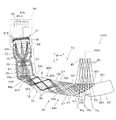
図1に示すように、本実施形態の虚像表示装置100は、眼鏡のような外観を有するヘッドマウントディスプレイであり、この虚像表示装置100を装着した観察者又は使用者に対して虚像による画像光を視認させることができるとともに、観察者に外界像をシースルーで視認又は観察させることができる。虚像表示装置100は、観察者の眼前を透視可能に覆う第1及び第2光学部材101a,101bと、両光学部材101a,101bを支持する枠部102と、枠部102の左右両端から後方のつる部分(テンプル)104にかけての部分に付加された第1及び第2像形成本体部105a,105bとを備える。ここで、図面上で左側の第1光学部材101aと第1像形成本体部105aとを組み合わせた第1表示装置100Aは、右眼用の虚像を形成する部分であり、単独でも虚像表示装置として機能する。また、図面上で右側の第2光学部材101bと第2像形成本体部105bとを組み合わせた第2表示装置100Bは、左眼用の虚像を形成する部分であり、単独でも虚像表示装置として機能する。なお、虚像表示装置100は、撮像動作可能な小型のカメラCAを第1表示装置100Aの側方部分に有している。 As shown in FIG. 1, the virtual
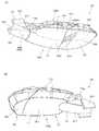
図2(A)は、虚像表示装置100の表側の外観を説明する斜視図であり、図2(B)は、虚像表示装置100を部分的に分解した表側の斜視図である。 FIG. 2A is a perspective view for explaining the front side appearance of the virtual
図示のように、虚像表示装置100に設けた枠部102は、上側に配置されるフレーム107と下側に配置されるプロテクター108とを備える。枠部102のうち、図2(A)に示す上側のフレーム107は、XZ面内でU字状に折れ曲がった細長い板状の部材であり、左右の横方向(X方向)に延びる正面部107aと、前後の奥行き方向(Z方向)に延びる一対の側面部107b,107cとを備える。フレーム107、すなわち正面部107aと側面部107b,107cとは、アルミダイカストその他の各種金属材料で形成された金属製の部分(アルミフレーム部)を主体として含んで構成されている。フレーム107がアルミフレーム部を含むことで、フレーム107を小型かつ軽量としつつ、十分な剛性を維持して装置全体としての耐久性を確保できる。なお、フレーム107は、一部に分解可能な樹脂製部分を有するものとしてもよい。フレーム107に分解可能な箇所が設けられれば、例えば、カメラCA等のためのハーネス等を組み込む際の作業性を向上させることができる。正面部107aの奥行き方向(Z方向)の幅は、第1及び第2光学部材101a,101bに対応する導光装置20の厚み又は幅よりも十分に厚いものとなっている。フレーム107の左側方、具体的には正面部107aにおける向かって左端部から側面部107bにかけての部分である側方端部65aには、第1光学部材101aと第1像形成本体部105aとがアライメントされネジ止めによって直接固定されることにより、支持されている。また、フレーム107の右側方、具体的には正面部107aにおける向かって右端部から側面部107cにかけての部分である側方端部65bには、第2光学部材101bと第2像形成本体部105bとがアライメントされネジ止めにより直接固定されることによって、支持されている。なお、第1光学部材101aと第1像形成本体部105aとは、嵌合によって互いにアライメントされ、第2光学部材101bと第2像形成本体部105bとは、嵌合によって互いにアライメントされる。また、光学系ユニットを構成する第1及び第2像形成本体部105a,105bは、カバー状の外装部材105dによってそれぞれ覆われている。言い換えると、外装部材105dは、光学系ユニットを構成する第1及び第2像形成本体部105a,105bを収納して保護する光学ユニット収納部OSとして機能している。 As illustrated, the
図2(A)及び2(B)に示すプロテクター108は、アンダーリム状の部材であり、図2(A)に示すフレーム107の下方に配置されて固定されている。プロテクター108の中央部108gは、フレーム107の中央部107gに嵌合及びネジ止めによって固定される。プロテクター108は、2段のクランク状に折れ曲がった細長い板状の部材であり、金属材料又は樹脂材料から一体的に形成されている。プロテクター108の第1先端部108iは、第1像形成本体部105aを覆う外装部材105dのうち外部材105eに設けた凹部105iに嵌合した状態で固定される。また、プロテクター108の第2先端部108jは、第2像形成本体部105bを覆うカバー状の外装部材105dのうち外部材105eに設けた凹部105jに嵌合した状態で固定される。 A
フレーム107は、第1及び第2像形成本体部105a,105bとこれらを覆う外装部材105d(光学ユニット収納部OS)とを支持する。また、フレーム107は、外装部材105dと協働して第1及び第2像形成本体部105a,105bの内部を保護する役割も有している。なお、フレーム107及びプロテクター108は、第1及び第2像形成本体部105a,105bに連結される根元側を除いた導光装置20の長円状の周囲部分と離間するか又は緩く接している。このため、中央の導光装置20と、フレーム107及びプロテクター108を含む枠部102との間に熱膨張率の差があっても、枠部102内での導光装置20の膨張が許容され、導光装置20に歪み、変形、破損が生じることを防止できる。なお、フレーム107が物体(例えば光学ユニット収納部OS)を支持するとは、光学ユニット収納部OS等がフレーム107に対して直接的に組み付けられることで、フレーム107に固定された状態が維持されている場合に限らず、他の部材を介して間接的に支持されている場合も含まれるものとする。 The
フレーム107に付随して、鼻受部40が設けられている。鼻受部40は、観察者の鼻に当接することによって枠部102を支持する役割を有する。つまり、枠部102は、鼻に支持される鼻受部40と耳に支持される一対のテンプル部104とによって、観察者の顔前に配置されることになる。鼻受部40は、枠部102を構成する一方のフレーム107の正面部107aの中央部107gにおいて、枠部102を構成する他方のプロテクター108の中央部108gに挟まれるようにして、ねじ止めによって固定されている。 A
以上のような構成により、光学ユニット収納部OSは、装着時において、観察者の側頭部側に配置されており、フレーム107は、観察者の上頭部側において、観察者の眼の並ぶ横方向に沿って眼前部分から観察者の側頭部側に向かって延び、上頭部側から光学ユニット収納部OSと導光装置20とを支持している状態となっている。 With the configuration as described above, the optical unit storage portion OS is disposed on the temporal side of the observer when worn, and the
虚像表示装置100が光学ユニットを収納した光学ユニット収納部OS(外装部材105d)を観察者の側頭部に配置する構成である場合、眼鏡と比べて大型の装置が側頭部の外側に付随するものとなっているため、装着時における装置による突起感が甚だしく、見た目が悪くなる可能性がある。これに対して、本実施形態の虚像表示装置100は、フレーム107を光学ユニット収納部OSよりも観察者の鼻に近い側に配置すること等によって、装置全体の外観をより眼鏡の形態に近づけた形状とし、見た目のボリューム感を抑えすっきりした印象を与えるデザインになっている。 When the virtual
以下、虚像表示装置100の光学系の構成について説明する。まず、図3(A)に示すように、第1表示装置100Aは、投影用の光学系である投射透視装置70と、映像光を形成する画像表示装置80とを備えると見ることができる。投射透視装置70は、第1像形成本体部105aによって形成された画像を虚像として観察者の眼に投射する役割を有する。投射透視装置70は、導光及び透視用の導光部材10と、透視用の光透過部材50と、結像用の投射レンズ30とを備える。つまり、第1光学部材101a又は導光装置20は、導光部材10と光透過部材50とで構成され、第1像形成本体部105aは、画像表示装置80と投射レンズ30とで構成される。 Hereinafter, the configuration of the optical system of the virtual
以下、図3(B)、4等を参照して、第1像形成本体部105aを構成する画像表示装置80と投射レンズ30とについて説明する。 Hereinafter, the
画像表示装置80は、照明光を射出する照明装置81と、透過型の空間光変調装置である映像表示素子82と、照明装置81及び映像表示素子82の動作を制御する駆動制御部84とを有する。 The
画像表示装置80の照明装置81は、赤、緑、青の3色を含む光を発生する光源81aと、この光源からの光を拡散させて矩形断面の光束にするバックライト導光部81bとを有する。映像表示素子82は、例えば液晶表示デバイスで形成され、照明装置81からの照明光を空間的に変調して動画像等の表示対象となるべき画像光を形成する。駆動制御部84は、光源駆動回路84aと、液晶駆動回路84bとを備える。光源駆動回路84aは、照明装置81に電力を供給して安定した輝度の照明光を射出させる。液晶駆動回路84bは、映像表示素子82に対して画像信号又は駆動信号を出力することにより、透過率パターンとして動画や静止画の元になるカラーの映像光又は画像光を形成する。なお、液晶駆動回路84bに画像処理機能を持たせることができるが、外付けの制御回路に画像処理機能を持たせることもできる。 The
投射レンズ30は、構成要素として3つの光学素子31〜33を備える投射光学系であり、これらの光学素子31〜33を収納して支持する鏡筒39を含む。光学素子31〜33は、例えば非球面レンズであり、導光部材10の一部と協働して導光部材10の内部に映像表示素子82の表示像に対応する中間像を形成する。鏡筒39は、前端側に矩形枠状の係合部材39aを有する。係合部材39aは、導光部材10の第2導光部分12側の先端部と嵌合することで、鏡筒39に対する導光部材10の位置決めを可能にしている。 The
なお、映像表示素子82は、筐体状の素子用ケース88の内部に収納され、移動しないように保持されている。素子用ケース88は、嵌合によって映像表示素子82の第1基板82aを支持する第1支持部分88aと、映像表示素子82の第2基板82bを覆う第2支持部分88bとを含む。両支持部分88a,88bは、遮光性の樹脂材料で形成された成形品である。 The
以上のように、虚像表示装置100のうち、映像表示素子82及び投射レンズ30は、画像を形成し投射をするための光学ユニット(図2(B)等に示す像形成本体部105a,105bに相当するもの)である。さらに、図5に模式的に示すように、映像表示素子82(図3(A)等参照)を収納する素子用ケース88や、投射レンズ30を構成する光学素子31〜33(図3(B)等参照)を収納した鏡筒39は、光学ユニット収納部OSに支持されて収納され、保護されている。なお、図示のように、素子用ケース88は、光学ユニット収納部OSの内壁面ISに対してクリアランスの領域SPをもった状態で収納されている。これにより、素子用ケース88内の映像表示素子82は、外部からの衝撃に直接的には影響を受けない状態が保たれている。 As described above, in the virtual
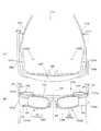
以下、図6を参照して、虚像表示装置100の外観形状の特徴について説明する。なお、図6(A)は、虚像表示装置100についての外観の様子を示す平面図であり、図6(B)は、正面図である。なお、図6は、模式的に外観を示すものであり、一部の部材については、図示を省略化或いは簡略化している。 Hereinafter, the features of the external shape of the virtual
図示のように、虚像表示装置100において、フレーム107のうち周辺側の縁を外縁107eとし、光学ユニット収納部OSのうち周辺側の縁を外縁OSeとする。フレーム107の外縁107eは、光学ユニット収納部OSの外縁OSeと比較して、観察者の眼の並ぶ横方向に関して観察者の鼻を配置すべき位置に近い側に配置されている。 As illustrated, in the virtual
ここで、フレーム107の外縁107eが光学ユニット収納部OSの外縁OSeよりも観察者の眼の並ぶ横方向に関して観察者の鼻に位置に近い側に配置されているとは、以下のように定義するものとする。まず、図6(B)に示すように、観察者の眼の並ぶ横方向に関して中央側にあり横方向に垂直な縦方向に延びて、観察者の鼻がある位置を示す基準となる軸を中心軸AAとする。次に、横方向に関して、フレーム107の外縁107eのうち中心軸AAから最も遠い部分である外縁端部の位置を第1位置FT1とし、光学ユニット収納部OSの外縁OSeのうち中心軸AAから最も遠い部分である外縁端部の位置を第2位置FT2とする。この場合に、第1位置FT1と第2位置FT2とを比較して、外第1位置FT1が第2位置FT2よりも観察者の鼻に近いすなわち中心軸AAに近い位置であれば、外縁107eが外縁OSeよりも観察者の眼の並ぶ横方向に関して観察者の鼻に位置に近い側に配置されているものとする。図示のように、虚像表示装置100が左右一対の両眼視のタイプの場合、フレーム107のほうが観察者の眼の並ぶ横方向に関して相対的に中央寄りにあることになる。言い換えると、フレーム107に比べて、光学ユニット収納部OSが外側にはみ出した部分があることになる。 Here, the
図示の場合、フレーム107は、光学ユニット収納部OSを下垂状に配置した状態で支持しており、フレーム107の外縁107eが光学ユニット収納部OSの外縁OSeよりも観察者の眼の並ぶ横方向に関して観察者の鼻に位置に近い側に配置されており、小型化されたものとなっている。また、この結果として、例えば図6(B)に示すように、フレーム107と光学ユニット収納部OSとの間には、段差STが設けられた状態となっている。さらに、図示の場合、フレーム107が相対的に明るい膨張色で塗装される一方、光学ユニット収納部OSが相対的に暗い縮小色で塗装されるものとすることで、両者の間に色に関するコントラストを設けている。これにより、外観形状にメリハリをつけ、横方向に関して出っ張りやすい光学ユニット収納部OSを、相対的に小さく見せて虚像表示装置100の全体についてコンパクトであるような印象を与えることができる。 In the case shown in the figure, the
また、虚像表示装置100が以上のような構造となっている場合、例えば、フレーム107に代えて投射レンズ30等の光学ユニットのみならず導光装置20までの光学系全体をケース状の部材で覆うような構造となっている場合と比べて、より眼鏡の形態に近づけた形状とすることができる。また、全体を外側から覆うようなものがなくフレーム107が内側に設けられた骨格のようになっていることで、見た目のボリューム感を抑えたデザインにすることができる。 When the virtual
以上により、虚像表示装置100は、装置全体の外観をより眼鏡の形態に近づけた形状とし、外部から見た場合にすっきりした印象を与えるものとになっている。 As described above, the virtual
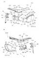
以下、他の部分の構成等について説明する。まず、図7を参照して、導光装置20の構成について説明し、図8において、第1表示装置100Aを構成する導光装置20や鏡筒39等の各部について、フレーム107へ組み付ける様子を説明する。 Hereinafter, the configuration of other parts will be described. First, the configuration of the
図7に示すように、導光部材10と光透過部材50とは、互いに固定されて一体的な導光装置20を構成している。導光装置20は、映像の光を内部で反射させつつ観察者の眼に導く光透過性の光学ブロック状又はプリズム状の部材である。導光装置20のうち周囲部分に囲まれた本体部分は、長円状の輪郭を有する。ここで、光透過部材50は、導光部材10の先端側、すなわち射出側又は光射出側の第1導光部分11に連結するようにその延長方向に配置され、接着剤を利用した接合によって第1導光部分11に固定されている。導光部材10及び光透過部材50を組み合わせた導光装置20は、図1における第1光学部材101aに相当し、投射透視装置70の投射レンズ(投射光学系)30と表示用の画像パターンを形成する画像表示装置80とは、図1における第1像形成本体部105aに相当する。導光装置(光学部材)20の周囲部分のうち、フレーム107に近い上辺側には、フレーム107下面に設けられている制限部107n(図8(B)参照)に嵌め込まれるリブ10nが形成されている。この第1のリブ10nの存在により、導光装置20の奥行き方向(Z方向)に関する変位が制限される。 As shown in FIG. 7, the
以下、図8等を参照して、第1表示装置100Aのフレーム107への組付けについて説明する。第1像形成本体部105aを構成する画像表示装置80の映像表示素子82は、突起部材(嵌合部)88u,88vを利用して、投射レンズ30の鏡筒39の後端部39hに固定される。映像表示素子82を鏡筒39に固定する際には、映像表示素子82を光軸に垂直な方向に微少変位させて鏡筒39に対してアライメント又は位置調整を行う。なお、映像表示素子82の背面(投射レンズ30の反対側)には、予め薄板状の照明装置81が取り付けられている。投射レンズ30は、その鏡筒39に埋め込むように形成された取付部39gを利用してフレーム107の側方端部65aに設けた第1固定部61fに直接固定されている。このような固定の際、第1固定部61fの裏面68fと取付部39gの上端面等とが当接してアライメントが達成され、ネジ孔61sを介してネジ61tを取付部39gにねじ込むことで着脱可能で確実な固定が可能になる。この際、フレーム107のボス孔61xに鏡筒39に設けたボス39xが嵌合して鏡筒39の回転が規制され回転に関する位置決めも行われる。一方、第1光学部材101aである導光装置20は、そのネック部に形成された突起状の取付部10gを利用して、フレーム107の側方端部65aに設けた第2固定部61eに直接固定されている。取付部10gは、導光装置20の入射側又は光入射側の部分、具体的には第1導光部分11と第2導光部分12との境界周辺において周囲に拡張するように立設されている。このような固定の際、第2固定部61eの前側部分に設けた突当て面68eと取付部10gの裏面10kとが当接してアライメントが達成され、ネジ孔61uを介してネジ61vをネジ孔10uにねじ込むことで着脱可能で確実な固定が可能になる。 Hereinafter, the assembly of the
導光装置20は、導光部材10の第2導光部分12側の先端部12jが投射レンズ30の鏡筒39の前端側に設けられて開口する矩形枠状の係合部材39aに嵌合することで、投射レンズ30に対して位置決めされた状態で係止される。つまり、導光装置20に設けた導光部材10をフレーム107の第2固定部61eに固定する際に、第2導光部分12側の先端部12jを鏡筒39の係合部材39a内に嵌合するように挿入する。この際、先端部12jの側面12mが係合部材39aの内面39mと当接してアライメントが達成される。その後、詳細な説明は省略するが、フレーム107に対して中央部107gにおいて鼻受部40を挟むようにプロテクター108を固定する。以上の工程によって、フレーム107と投射透視装置70とプロテクター108とのアセンブリーを得ることができる。 The
その後、図2(A)に示すように、外装部材105dのうち外部材105eをフレーム107及び投射透視装置70のアセンブリーに固定する。外部材105eは、フレーム107や投射レンズ30との嵌合、投射レンズ30の取付部39gに対してのネジ締結等によって固定される。この際、フレーム107に既に固定されているプロテクター108の先端部108i,108jを外部材105eに形成された凹部105iに嵌合させて固定することになる。次に、内部材105fを外部材105eに嵌合させ、ネジ止めによって外部材105eに固定する。これにより、内部材105fと外部材105eとに挟まれた空間内に、投射透視装置70を構成する導光装置20の根元側及び投射レンズ30と、画像表示装置80と、フレーム107の側面部107b,107cの一部とが収納される。以上のように組み付けられることで、虚像表示装置100において、投射レンズ30等を収納する光学ユニット収納部OSが、装着時において、観察者の側頭部側に配置されており、フレーム107が、観察者の上頭部側において、観察者の眼の並ぶ横方向に沿って眼前部分から観察者の側頭部側に向かって延び、上頭部側から光学ユニット収納部OSと導光装置20とを支持している状態とすることができる。 Thereafter, as shown in FIG. 2A, the
テンプル部104は、フレーム107に設けた一対の側面部107b,107cの先端に固定されている。テンプル部104と側面部107b,107cとの連結部は、ヒンジ構造を有するものとでき、この場合、テンプル部104の折畳みが可能になる。 The
なお、図1に示す第2表示装置100Bは、第1表示装置100Aと同様の構造を有し、第1表示装置100Aを左右対称に反転させただけであるので、第2表示装置100Bの構造、機能、組立て等についての説明は省略する。 The
図4を参照して、投射透視装置70等の機能、動作等の詳細について説明する。投射透視装置70のうち、導光装置20の一部である導光部材10は、平面視において顔面に沿うように湾曲した円弧状の部材である。導光部材10のうち、第1導光部分11は、鼻に近い中央側つまり光射出側に配置され、光学的な機能を有する側面として、第1面S11と、第2面S12と、第3面S13とを有し、第2導光部分12は、鼻から離れた周辺側つまり光入射側に配置され、光学的な機能を有する側面として、第4面S14と、第5面S15とを有する。このうち、第1面S11と第4面S14とが連続的に隣接し、第3面S13と第5面S15とが連続的に隣接する。また、第1面S11と第3面S13との間に第2面S12が配置され、第4面S14と第5面S15とは大きな角度を成して隣接している。 With reference to FIG. 4, details of functions and operations of the
導光部材10において、第1面S11は、Z軸に平行な射出側光軸AXOを中心軸とする自由曲面であり、第2面S12は、XZ面に平行な基準面(図示の断面)に含まれZ軸に対して傾斜した光軸AX1を中心軸とする自由曲面であり、第3面S13は、射出側光軸AXOを中心軸とする自由曲面である。第4面S14は、XZ面に平行な上記基準面に含まれZ軸に対して傾斜した一対の光軸AX3,AX4の2等分線に平行な光軸AX5を中心軸とする自由曲面であり、第5面S15は、XZ面に平行な上記基準面に含まれるとともにZ軸に対して傾斜した一対の光軸AX4,AX5の2等分線又はこれに対して小角度をなす線を中心軸とする自由曲面である。なお、以上の第1〜第5面S11〜S15は、水平(又は横)に延びXZ面に平行で光軸AX1〜AX5等が通る基準面(図示の断面)を挟んで、鉛直(又は縦)のY軸方向に関して対称な形状を有している。 In the
導光部材10のうち本体10sは、可視域で高い光透過性を示す樹脂材料で形成されており、例えば金型内に熱可塑性樹脂を注入・固化させることにより成形する。なお、本体10sの材料としては、例えばシクロオレフィンポリマー等を用いることができる。本体10sは、一体形成品とされているが、導光部材10は、既に説明したように機能的に第1導光部分11と第2導光部分12とに分けて考えることができる。第1導光部分11は、映像光GLの導波及び射出を可能にするとともに、外界光HLの透視を可能にする。第2導光部分12は、映像光GLの入射及び導波を可能にする。 The
第1導光部分11において、第1面S11は、映像光GLを第1導光部分11外に射出させる屈折面として機能するとともに、映像光GLを内面側で全反射させる全反射面として機能する。第1面S11は、眼EYの正面に配されるものであり、観察者に対し凹面形状を成している。なお、第1面S11は、本体10sの表面に施されたハードコート層27によって形成される面である。 In the first
第2面S12は、本体10sの表面であり、当該表面にハーフミラー層15が付随している。このハーフミラー層15は、光透過性を有する反射膜(すなわち半透過反射膜)である。ハーフミラー層(半透過反射膜)15は、第2面S12の全体ではなく、第2面S12を主にY軸に沿った鉛直方向に関して狭めた部分領域PA上に形成されている(図7(A)参照)。ハーフミラー層15は、本体10sの下地面のうち部分領域PA上に、金属反射膜や誘電体多層膜を成膜することにより形成される。ハーフミラー層15の映像光GLに対する反射率は、シースルーによる外界光HLの観察を容易にする観点で、想定される映像光GLの入射角範囲において10%以上50%以下とする。具体的な実施例のハーフミラー層15の映像光GLに対する反射率は、例えば20%に設定され、映像光GLに対する透過率は、例えば80%に設定される。 The second surface S12 is the surface of the
第3面S13は、映像光GLを内面側で全反射させる全反射面として機能する。第3面S13は、眼EYの正面に配されるものであり、第1面S11と同様に観察者に対し凹面形状を成しており、第1面S11と第3面S13とを通過させて外界光HLを見たときに、視度が略0になっている。なお、第3面S13は、本体10sの表面に施されたハードコート層27によって形成される面である。 The third surface S13 functions as a total reflection surface that totally reflects the video light GL on the inner surface side. The third surface S13 is arranged in front of the eye EY, and has a concave shape with respect to the observer, like the first surface S11, and allows the first surface S11 and the third surface S13 to pass therethrough. When the external light HL is viewed, the diopter is substantially zero. The third surface S13 is a surface formed by the
第2導光部分12において、第4面S14は、映像光GLを内面側で全反射させる全反射面として機能する。第4面S14は、映像光GLを第2導光部分12内に入射させる屈折面としても機能する。なお、第4面S14は、本体10sの表面に施されたハードコート層27によって形成される面である。 In the second
第2導光部分12において、第5面S15は、既述のように、本体10sの表面上に無機材料で形成される光反射膜RMを成膜することで形成され、反射面として機能する。 In the second
光透過部材50は、既述のように導光部材10と一体的に固定され1つの導光装置20となっている。光透過部材50は、導光部材10の透視機能を補助する部材(補助光学ブロック)であり、光学的な機能を有する側面として、第1透過面S51と、第2透過面S52と、第3透過面S53とを有する。ここで、第1透過面S51と第3透過面S53との間に第2透過面S52が配置されている。第1透過面S51は、導光部材10の第1面S11を延長した曲面上にあり、第2透過面S52は、当該第2面S12に対して接着層CCによって接合され一体化されている曲面であり、第3透過面S53は、導光部材10の第3面S13を延長した曲面上にある。このうち第2透過面S52と導光部材10の第2面S12とは、薄い接着層CCを介しての接合によって一体化されるため、略同じ曲率の形状を有する。 The
光透過部材(補助光学ブロック)50は、可視域で高い光透過性を示し、光透過部材50の本体部分は、導光部材10の本体10sと略同一の屈折率を有する熱可塑性樹脂材料で形成されている。なお、光透過部材50は、本体部分を導光部材10の本体10sに接合した後、接合された状態で本体10sとともにハードコートによる成膜がなされて形成されるものである。つまり、光透過部材50は、導光部材10と同様、本体部分の表面にハードコート層27が施されたものとなっている。第1透過面S51と第3透過面S53とは、本体部分の表面に施されたハードコート層27によって形成される面である。 The light transmissive member (auxiliary optical block) 50 exhibits high light transmittance in the visible range, and the main body portion of the
以下、虚像表示装置100における映像光GL等の光路について説明する。映像表示素子(映像素子)82から射出された映像光GLは、投射レンズ30によって収束されつつ、導光部材10に設けた正の屈折力を有する第4面S14に入射する。 Hereinafter, an optical path of the image light GL and the like in the virtual
導光部材10の第4面S14を通過した映像光GLは、収束しつつ進み、第2導光部分12を経由する際に、比較的弱い正の屈折力を有する第5面S15で反射され、第4面S14に内側から再度入射して反射される。 The video light GL that has passed through the fourth surface S14 of the
第2導光部分12の第4面S14で反射された映像光GLは、第1導光部分11において、比較的弱い正の屈折力を有する第3面S13に入射して全反射され、比較的弱い負の屈折力を有する第1面S11に入射して全反射される。なお、映像光GLは、第3面S13を通過する前後において、導光部材10中に中間像を形成する。この中間像の像面IIは、映像表示素子82の像面OIに対応するものである。 The image light GL reflected by the fourth surface S14 of the second
第1面S11で全反射された映像光GLは、第2面S12に入射するが、特にハーフミラー層15に入射した映像光GLは、このハーフミラー層15を部分的に透過しつつも部分的に反射されて第1面S11に再度入射して通過する。なお、ハーフミラー層15は、ここで反射される映像光GLに対して比較的強い正の屈折力を有するものとして作用する。また、第1面S11は、これを通過する映像光GLに対して負の屈折力を有するものとして作用する。 The image light GL totally reflected by the first surface S11 is incident on the second surface S12. In particular, the image light GL incident on the
第1面S11を通過した映像光GLは、観察者の眼EYの瞳又はその等価位置に略平行光束として入射する。つまり、観察者は、虚像としての映像光GLにより、映像表示素子(映像素子)82上に形成された画像を観察することになる。 The video light GL that has passed through the first surface S11 enters the pupil of the observer's eye EY or an equivalent position thereof as a substantially parallel light beam. That is, the observer observes an image formed on the video display element (video element) 82 by the video light GL as a virtual image.
一方、外界光HLのうち、導光部材10の第2面S12よりも−X側に入射するものは、第1導光部分11の第3面S13と第1面S11とを通過するが、この際、正負の屈折力が相殺されるとともに収差が補正される。つまり、観察者は、導光部材10越しに歪みの少ない外界像を観察することになる。同様に、外界光HLのうち、導光部材10の第2面S12よりも+X側に入射するもの、つまり、光透過部材50に入射したものは、これに設けた第3透過面S53と第1透過面S51とを通過する際に、正負の屈折力が相殺されるとともに収差が補正される。つまり、観察者は、光透過部材50越しに歪みの少ない外界像を観察することになる。さらに、外界光HLのうち、導光部材10の第2面S12に対応する光透過部材50に入射するものは、第3透過面S53と第1面S11とを通過する際に、正負の屈折力が相殺されるとともに収差が補正される。つまり、観察者は、光透過部材50越しに歪みの少ない外界像を観察することになる。なお、導光部材10の第2面S12と光透過部材50の第2透過面S52とは、略同一の曲面形状をともに有し、略同一の屈折率をともに有し、両者の隙間が略同一の屈折率の接着層CCで充填されている。つまり、導光部材10の第2面S12や光透過部材50の第2透過面S52は、外界光HLに対して屈折面として作用しない。 On the other hand, among the external light HL, the light incident on the −X side from the second surface S12 of the
ただし、ハーフミラー層15に入射した外界光HLは、このハーフミラー層15を部分的に透過しつつも部分的に反射されるので、ハーフミラー層15に対応する方向からの外界光HLは、ハーフミラー層15の透過率に弱められる。その一方で、ハーフミラー層15に対応する方向からは、映像光GLが入射するので、観察者は、ハーフミラー層15の方向に映像表示素子(映像素子)82上に形成された画像とともに外界像を観察することになる。 However, since the external light HL incident on the
導光部材10内で伝搬されて第2面S12に入射した映像光GLのうち、ハーフミラー層15で反射されなかったものは、光透過部材50内に入射するが、光透過部材50に設けた不図示の反射防止部によって導光部材10に戻ることが防止される。つまり、第2面S12を通過した映像光GLが光路上に戻されて迷光となることが防止される。また、光透過部材50側から入射してハーフミラー層15で反射された外界光HLは、光透過部材50に戻されるが、光透過部材50に設けた上述の不図示の反射防止部によって導光部材10に射出されることが防止される。つまり、ハーフミラー層15で反射された外界光HLが光路上に戻されて迷光となることが防止される。 Of the image light GL propagated in the
以上の説明から明らかなように、本実施形態の虚像表示装置100によれば、フレーム107によって、映像表示素子82や投射レンズ30を収納する光学ユニット収納部OSと導光装置20とを支持して、装置全体のうち光学的機能を有する箇所の耐久性を維持している。この際、フレーム107は、光学ユニット収納部OSよりも観察者の鼻に近い側に配置され小型化されたものとなっている。これにより、虚像表示装置100は、装置全体として見た目にコンパクトである印象を与えることができる。さらに、フレーム107の小型化により虚像表示装置100全体としても軽量化を図ることが可能となる。また、装置全体をケース状の部材で全体を覆う構造と比べると、フレーム107の構成等によって、より眼鏡の形態に近づけた形状とすることができ、見た目のボリューム感を抑えたデザインにすることができる。 As is clear from the above description, according to the virtual
以下、図9を参照して、本実施形態に係る虚像表示装置の一変形例について説明する。なお、図9の虚像表示装置100は、図6に対応する図であり、図1等に示す虚像表示装置100のものと比較して、カメラCAの位置やフレーム107、プロテクター108の部分的な形状等の一部の構成が異なるが、これら以外の他の部分については、図1、図6等の場合と同様であるので、各部の詳しい説明については省略する。 Hereinafter, a modification of the virtual image display device according to the present embodiment will be described with reference to FIG. The virtual
図9(A)及び9(B)に示すように、フレーム107は、アルミダイカストで形成されたアルミフレーム部107mを主体として含んで構成され、一部に分解可能な樹脂製部分である樹脂部107pを有している。図示のように、樹脂部107pは、観察者の眼の並ぶ横方向に沿って延びた棒状の形状を有しており、樹脂部107pとアルミフレーム部107mとを分離する境界部分であるスリットSLも観察者の眼の並ぶ横方向に沿って延びるように形成されている。この場合、中央側に配置されたカメラCAのためのハーネス等を、樹脂部107pとアルミフレーム部107mとを分解(分離)した状態で組み込むことができるので、カメラCAの組み付け作業を向上させることができる。なお、フレーム107の場合、特に負荷がかかり剛性を要するのは、眼の並ぶ横方向からつる部分(テンプル部104)が延びる方向に折り曲げられる部分、すなわち通常の眼鏡で言うヨロイに相当する部分である。図示の場合、このヨロイに相当する部分については、アルミフレーム部107mで形成していることによって、十分な強度が確保されている。 As shown in FIGS. 9 (A) and 9 (B), the
なお、フレーム107のうち、アルミフレーム部107mと樹脂部107pとで色を塗り分けることで、外観の印象を変化させ、すっきりした印象のデザインとすることが可能である。 In the
以上、実施形態に即して本発明を説明したが、本発明は、上記の実施形態に限られるものではなく、その要旨を逸脱しない範囲において種々の態様において実施することが可能であり、例えば次のような変形も可能である。 As mentioned above, although this invention was demonstrated according to embodiment, this invention is not restricted to said embodiment, In the range which does not deviate from the summary, it is possible to implement in various aspects, for example, The following modifications are possible.
上記実施形態では、画像表示装置80において、透過型の液晶表示デバイス等からなる映像表示素子82を用いているが、画像表示装置80としては、透過型の液晶表示デバイス等からなる映像表示素子82に限らず種々のものを利用可能である。例えば、反射型の液晶表示デバイスを用いた構成も可能であり、液晶表示デバイス等からなる映像表示素子82に代えてデジタル・マイクロミラー・デバイス等を用いることもできる。また、画像表示装置80として、LEDアレイやOLED(有機EL)などに代表される自発光型素子を用いることができる。 In the above-described embodiment, the
映像表示素子82と投射レンズ30との固定方法は、突起部材(嵌合部)88u,88vを利用するものに限らず、映像表示素子82を鏡筒39に直接固定する様々な手法を用いることができる。 The fixing method of the
枠部102については、実施形態に例示した形状又は眼鏡のフレームに似た外観に限らず、投射レンズ30と導光装置20とを橋渡しすることができる様々な形状とできる。 The
上記実施形態では、フレーム107と投射レンズ30とが別体でネジ止めによって投射レンズ30をフレーム107に固定しているが、投射レンズ30の鏡筒39をフレーム107と一体成形することもできる。鏡筒39をフレーム107と一体成形する方法として、アウトサート成形、ダイカスト一体成形後の鏡筒部削り出し等の手法がある。 In the above-described embodiment, the
導光装置20又は投射レンズ30については、ネジ止めによる締結に限らず、様々な手法でフレーム107に固定することができる。 The
上記実施形態では、投射レンズ30の鏡筒39に導光装置20との係合部材39aを設けているが、導光装置20側に例えば鏡筒39を挟むように鏡筒39と嵌合する係合部材を設けることができる。 In the above embodiment, the engaging
上記実施形態では、ハーフミラー層(半透過反射膜)15が横長の矩形領域に形成されるとしたが、ハーフミラー層15の輪郭は用途その他の使用に応じて適宜変更することができる。また、ハーフミラー層15の透過率や反射率も用途その他に応じて変更することができる。 In the above embodiment, the half mirror layer (semi-transmissive reflection film) 15 is formed in a horizontally long rectangular region. However, the contour of the
上記実施形態では、ハーフミラー層15が単なる半透過性の膜(例えば金属反射膜や誘電体多層膜)であるとしたが、ハーフミラー層15は、平面又は曲面のホログラム素子に置き換えることができる。 In the above embodiment, the
上記実施形態では、映像表示素子82における表示輝度の分布を特に調整していないが、位置によって輝度差が生じる場合等においては、表示輝度の分布を不均等に調整することができる。 In the above embodiment, the display luminance distribution in the
上記の説明では、一対の表示装置100A,100Bを備える虚像表示装置100について説明しているが、単一の表示装置とできる。つまり、右眼及び左眼の双方に対応して、一組ずつ投射透視装置70及び画像表示装置80を設けるのではなく、右眼又は左眼のいずれか一方に対してのみ投射透視装置70及び画像表示装置80を設け、画像を片眼視する構成にしてもよい。この場合、フレーム107やテンプル部104は、例えば図1等に示すままで左右対称に配置する形状とすることができる。また、例えば図10(A)に示すように、右眼に対してのみ画像表示装置80等の画像形成のための装置を設ける場合において、画像を視認させない左眼側には、フレーム107やテンプル部104、鼻受部40等の装置を支持するための部材のみ配置する構造としてもよい。また、画像を片眼視する場合に、例えば図10(B)に示すように、画像を視認させない左眼側には、導光装置を設けず、眼前に素通しのプラスチックレンズGGを配置して、外観上は左右対称の形状であるような態様としてもよい。図示の場合、左眼側のボックス部BSは、右縁側の光学ユニット収納部OSとの外観的対称性を保つために設けられるものとなり、内部に光学系を有しないものとなる。なお、この場合において、ボックス部BSの内部に重心的なバランスをとるための部材を収納するものとしてもよい。 In the above description, the virtual
上記実施形態では、導光部材10の第1面S11及び第3面S13において、表面上にミラーやハーフミラー等を施すことなく空気との界面により映像光を全反射させて導くものとしているが、本願発明の虚像表示装置100における全反射については、第1面S11又は第3面S13上の全体又は一部にミラーコートや、ハーフミラー膜が形成されてなされる反射も含むものとする。例えば、映像光の入射角度が全反射条件を満たした上で、上記第1面S11又は第3面S13の全体又は一部にミラーコート等が施され、実質的に全ての映像光を反射する場合も含まれる。また、十分な明るさの映像光を得られるのであれば、多少透過性のあるミラーによって第1面S11又は第3面S13の全体又は一部がコートされていてもよい。 In the above embodiment, the first light S11 and the third surface S13 of the
上記の説明では、導光部材10等が眼EYの並ぶ横方向に延びているが、導光部材10を縦方向に延びるように配置することもできる。この場合、導光部材10は、例えば上部での片持ち状態によって支持される。 In the above description, the
また、対向して配置される第1面S11と第3面S13は、観察者に対し凹面形状を成しているものとしているが、第1面S11及び第3面S13が平行な平面形状であるものとしてもよい。この場合、観察者が第1面S11及び第3面S13を透過して外界を見た場合に視度を0とすることができる。また、第1面S11及び第3面S13が平行な平面形状である場合において、例えば第1面S11及び第3面S13以外の他の面については曲面を持たせることで、中間像を形成させるものとしてもよく、中間像を形成しない構成の画像形成であるものとすることも可能である。以上のような構成においても、上述の場合と同様に例えばフレームと光学ユニット収納部との間に段差が設けられた形状を有することによって、外観形状にメリハリをつけ、見た目のボリューム感を抑えることができる。 In addition, the first surface S11 and the third surface S13 that are arranged to face each other have a concave shape with respect to the observer, but the first surface S11 and the third surface S13 have a parallel planar shape. There may be. In this case, the diopter can be set to 0 when the observer sees the outside through the first surface S11 and the third surface S13. In addition, when the first surface S11 and the third surface S13 are parallel planar shapes, for example, the other surfaces other than the first surface S11 and the third surface S13 are provided with curved surfaces to form an intermediate image. It is also possible to use an image forming apparatus that does not form an intermediate image. Even in the configuration described above, as in the case described above, for example, by having a shape in which a step is provided between the frame and the optical unit housing portion, the appearance shape is sharpened and the volume of appearance is suppressed. Can do.
AX4〜AX5…光軸、 GL…映像光、 HL…外界光、 OI…像面、 PA…部分領域、 RM…光反射膜、 S11〜S15…第1〜第5面、 S51〜S53…透過面、 31〜33…光学素子、 10…導光部材、 10g…取付部、 10s…本体、 11,12…導光部分、 15…ハーフミラー層、 20…導光装置、 30…投射レンズ、 39…鏡筒、 39a…係合部材、 39g…取付部、 39h…後端部、 40…鼻受部、 50…光透過部材、 61e,61f…固定部、 65a,65b…側方端部、 70…投射透視装置、 80…画像表示装置、 81…照明装置、 81a…光源、 81b…バックライト導光部、 82…映像表示素子、 84…駆動制御部、 84a…光源駆動回路、 84b…液晶駆動回路、 88…素子用ケース、 100…虚像表示装置、 100A,100B…表示装置、 101a,101b…光学部材、 102…枠部、 104…テンプル部、 105a,105b…像形成本体部(光学ユニット)、 105d…外装部材、 107…フレーム、 107e…外縁、 107m…アルミフレーム部、 107p…樹脂部、 108…プロテクター、 OS…光学ユニット収納部、 OSe…外縁、 AA…中心軸、 CA…カメラ、 FT1…第1位置、 FT2…第2位置、 SL…スリット、 SP…領域、 ST…段差AX4 to AX5: Optical axis, GL: Video light, HL: External light, OI: Image plane, PA: Partial area, RM: Light reflection film, S11-S15: First to fifth surfaces, S51-S53: Transmission surface , 31 to 33: optical element, 10: light guide member, 10g: mounting portion, 10s ... main body, 11, 12 ... light guide portion, 15: half mirror layer, 20 ... light guide device, 30 ... projection lens, 39 ... Lens barrel, 39a ... engaging member, 39g ... mounting portion, 39h ... rear end portion, 40 ... nose receiving portion, 50 ... light transmitting member, 61e, 61f ... fixing portion, 65a, 65b ... side end portion, 70 ... Projection see-through device, 80 ... Image display device, 81 ... Illumination device, 81a ... Light source, 81b ... Back light guide unit, 82 ... Video display element, 84 ... Drive control unit, 84a ... Light source drive circuit, 84b ... Liquid crystal drive circuit , 88 Case for
Claims (12)
Translated fromJapanese前記映像素子を含む光学ユニットを収納する光学ユニット収納部と、
観察者の眼前に配置されるとともに、前記映像素子を含む前記光学ユニットからの光を観察者の眼に向けて画像を視認させる導光装置と、
画像形成に関する構成要素のうち、前記光学ユニット収納部を少なくとも支持するフレームと、
を備える虚像表示装置であって、
前記フレームの外縁は、前記光学ユニット収納部の外縁よりも、観察者の眼の並ぶ横方向に関して観察者の鼻を配置すべき位置に近い側に配置されている、虚像表示装置。An image element;
An optical unit storage section for storing an optical unit including the image element;
A light guide device that is disposed in front of the viewer's eyes and that visually recognizes an image by directing light from the optical unit including the video element toward the eyes of the viewer;
Of the components related to image formation, a frame that supports at least the optical unit storage unit,
A virtual image display device comprising:
The virtual image display device, wherein an outer edge of the frame is arranged closer to a position where an observer's nose is to be arranged in a lateral direction in which the observer's eyes are arranged than an outer edge of the optical unit housing portion.
前記光学ユニット収納部は、前記投射レンズを構成する光学素子を支持する鏡筒を内部に収納し、
前記鏡筒は、前記フレームに支持されている、請求項1から6までのいずれか一項に記載の虚像表示装置。As a part of the optical unit, further comprising a projection lens that projects the light from the video element toward the light guide device,
The optical unit storage unit stores therein a lens barrel that supports an optical element constituting the projection lens,
The virtual image display device according to claim 1, wherein the lens barrel is supported by the frame.
Priority Applications (3)
| Application Number | Priority Date | Filing Date | Title |
|---|---|---|---|
| JP2013096767AJP2014219468A (en) | 2013-05-02 | 2013-05-02 | Virtual image display device |
| US14/260,982US9465217B2 (en) | 2013-05-02 | 2014-04-24 | Virtual image display apparatus |
| CN201410177509.3ACN104133294A (en) | 2013-05-02 | 2014-04-29 | Virtual image display apparatus |
Applications Claiming Priority (1)
| Application Number | Priority Date | Filing Date | Title |
|---|---|---|---|
| JP2013096767AJP2014219468A (en) | 2013-05-02 | 2013-05-02 | Virtual image display device |
Publications (1)
| Publication Number | Publication Date |
|---|---|
| JP2014219468Atrue JP2014219468A (en) | 2014-11-20 |
Family
ID=51806033
Family Applications (1)
| Application Number | Title | Priority Date | Filing Date |
|---|---|---|---|
| JP2013096767AWithdrawnJP2014219468A (en) | 2013-05-02 | 2013-05-02 | Virtual image display device |
Country Status (3)
| Country | Link |
|---|---|
| US (1) | US9465217B2 (en) |
| JP (1) | JP2014219468A (en) |
| CN (1) | CN104133294A (en) |
Cited By (8)
| Publication number | Priority date | Publication date | Assignee | Title |
|---|---|---|---|---|
| CN105425395A (en)* | 2015-09-30 | 2016-03-23 | 上海理鑫光学科技有限公司 | Large-field-angle augmented reality glasses with glass solution |
| JP2016126204A (en)* | 2015-01-06 | 2016-07-11 | セイコーエプソン株式会社 | Image display device |
| EP3096205A1 (en) | 2015-05-21 | 2016-11-23 | Seiko Epson Corporation | Portable display device, display system and display method |
| US9651785B2 (en) | 2015-01-26 | 2017-05-16 | Seiko Epson Corporation | Display system, portable display device, display control device, and display method |
| WO2017087312A1 (en)* | 2015-11-19 | 2017-05-26 | Microsoft Technology Licensing, Llc | Low-stress waveguide mounting for head-mounted display device |
| US9779339B2 (en) | 2015-06-05 | 2017-10-03 | Seiko Epson Corporation | Printer, terminal device, and printing system |
| US10120633B2 (en) | 2015-01-26 | 2018-11-06 | Seiko Epson Corporation | Display system, portable display device, display control device, and display method |
| US11966054B2 (en) | 2018-05-15 | 2024-04-23 | Sony Corporation | Display device |
Families Citing this family (14)
| Publication number | Priority date | Publication date | Assignee | Title |
|---|---|---|---|---|
| JP6402444B2 (en)* | 2013-12-26 | 2018-10-10 | セイコーエプソン株式会社 | Virtual image display device |
| US9915823B1 (en)* | 2014-05-06 | 2018-03-13 | Google Llc | Lightguide optical combiner for head wearable display |
| JP2018165742A (en)* | 2017-03-28 | 2018-10-25 | セイコーエプソン株式会社 | Display device and light guide device |
| JP7018961B2 (en)* | 2017-06-06 | 2022-02-14 | アップル インコーポレイテッド | Optical system for electronic devices with display |
| CN109425985B (en)* | 2017-08-30 | 2020-08-28 | 芋头科技(杭州)有限公司 | Near-eye display system and near-eye display |
| JP2019082531A (en)* | 2017-10-30 | 2019-05-30 | ソニー株式会社 | Head-mounted display |
| JP7200637B2 (en)* | 2017-12-25 | 2023-01-10 | 株式会社リコー | Head-mounted display and display system |
| JP7128648B2 (en)* | 2018-04-25 | 2022-08-31 | 株式会社日立エルジーデータストレージ | head mounted display |
| US11327561B1 (en)* | 2018-09-27 | 2022-05-10 | Apple Inc. | Display system |
| CN112180593A (en)* | 2019-07-01 | 2021-01-05 | 苏州苏大维格科技集团股份有限公司 | Apparatus for presenting image and system for implementing augmented reality display |
| JP2021071604A (en)* | 2019-10-31 | 2021-05-06 | セイコーエプソン株式会社 | Light guide device, display device, and method for manufacturing light guide device |
| CN111610633B (en)* | 2020-06-23 | 2023-08-11 | 京东方科技集团股份有限公司 | Optical modules, electronic devices and glasses |
| CN116360100A (en)* | 2021-12-28 | 2023-06-30 | Oppo广东移动通信有限公司 | Augmented reality device and intelligent glasses |
| JP2023109305A (en)* | 2022-01-27 | 2023-08-08 | セイコーエプソン株式会社 | head mounted display |
Citations (10)
| Publication number | Priority date | Publication date | Assignee | Title |
|---|---|---|---|---|
| JPH09113860A (en)* | 1995-10-18 | 1997-05-02 | Sharp Corp | Head-mounted display |
| JP2002189464A (en)* | 2000-12-21 | 2002-07-05 | Canon Inc | Image display device and image display system |
| JP2009157290A (en)* | 2007-12-28 | 2009-07-16 | Konica Minolta Holdings Inc | Video display device and head mounted display |
| JP2009159381A (en)* | 2007-12-27 | 2009-07-16 | Brother Ind Ltd | Monocular image forming apparatus |
| US20100103078A1 (en)* | 2008-10-23 | 2010-04-29 | Sony Corporation | Head-mounted display apparatus |
| JP2010230716A (en)* | 2009-03-25 | 2010-10-14 | Olympus Corp | Head-mounted image display device |
| JP2011203378A (en)* | 2010-03-24 | 2011-10-13 | Olympus Corp | Head-mounted type image display device |
| JP2012163639A (en)* | 2011-02-04 | 2012-08-30 | Seiko Epson Corp | Virtual image display device |
| JP2013005201A (en)* | 2011-06-16 | 2013-01-07 | Sony Corp | Display device |
| WO2013025672A2 (en)* | 2011-08-18 | 2013-02-21 | Google Inc. | Wearable device with input and output structures |
Family Cites Families (13)
| Publication number | Priority date | Publication date | Assignee | Title |
|---|---|---|---|---|
| CN1125998C (en)* | 1998-01-28 | 2003-10-29 | 皇家菲利浦电子有限公司 | Head-mounted display |
| US6487021B1 (en)* | 1999-06-22 | 2002-11-26 | Koninklijke Philips Electronics N.V. | Head-mounted display |
| JP5212901B2 (en)* | 2008-09-25 | 2013-06-19 | ブラザー工業株式会社 | Glasses-type image display device |
| JP5131254B2 (en)* | 2009-07-15 | 2013-01-30 | ブラザー工業株式会社 | Attachment device for HMD |
| EP2372431A3 (en)* | 2010-03-24 | 2011-12-28 | Olympus Corporation | Head-mounted type display device |
| JP5678460B2 (en)* | 2010-04-06 | 2015-03-04 | ソニー株式会社 | Head-mounted display |
| US9223137B2 (en)* | 2010-10-08 | 2015-12-29 | Seiko Epson Corporation | Virtual image display apparatus |
| JP5699649B2 (en) | 2011-02-04 | 2015-04-15 | セイコーエプソン株式会社 | Virtual image display device |
| JP5698578B2 (en)* | 2011-03-24 | 2015-04-08 | オリンパス株式会社 | Head-mounted display device |
| JP2012252091A (en)* | 2011-06-01 | 2012-12-20 | Sony Corp | Display apparatus |
| US9311883B2 (en)* | 2011-11-11 | 2016-04-12 | Microsoft Technology Licensing, Llc | Recalibration of a flexible mixed reality device |
| US9075249B2 (en)* | 2012-03-07 | 2015-07-07 | Google Inc. | Eyeglass frame with input and output functionality |
| US20130258271A1 (en)* | 2012-03-28 | 2013-10-03 | Google Inc. | Sliding Frame |
- 2013
- 2013-05-02JPJP2013096767Apatent/JP2014219468A/ennot_activeWithdrawn
- 2014
- 2014-04-24USUS14/260,982patent/US9465217B2/ennot_activeExpired - Fee Related
- 2014-04-29CNCN201410177509.3Apatent/CN104133294A/enactivePending
Patent Citations (10)
| Publication number | Priority date | Publication date | Assignee | Title |
|---|---|---|---|---|
| JPH09113860A (en)* | 1995-10-18 | 1997-05-02 | Sharp Corp | Head-mounted display |
| JP2002189464A (en)* | 2000-12-21 | 2002-07-05 | Canon Inc | Image display device and image display system |
| JP2009159381A (en)* | 2007-12-27 | 2009-07-16 | Brother Ind Ltd | Monocular image forming apparatus |
| JP2009157290A (en)* | 2007-12-28 | 2009-07-16 | Konica Minolta Holdings Inc | Video display device and head mounted display |
| US20100103078A1 (en)* | 2008-10-23 | 2010-04-29 | Sony Corporation | Head-mounted display apparatus |
| JP2010230716A (en)* | 2009-03-25 | 2010-10-14 | Olympus Corp | Head-mounted image display device |
| JP2011203378A (en)* | 2010-03-24 | 2011-10-13 | Olympus Corp | Head-mounted type image display device |
| JP2012163639A (en)* | 2011-02-04 | 2012-08-30 | Seiko Epson Corp | Virtual image display device |
| JP2013005201A (en)* | 2011-06-16 | 2013-01-07 | Sony Corp | Display device |
| WO2013025672A2 (en)* | 2011-08-18 | 2013-02-21 | Google Inc. | Wearable device with input and output structures |
Non-Patent Citations (3)
| Title |
|---|
| "日常生活で利用可能な ウェアラブルディスプレイの試作機を開発 スマートフォンとの連携も可能に", [ONLINE], JPN6017033440, 5 July 2012 (2012-07-05), ISSN: 0003633333* |
| 加納恵: "携帯型ホームシアター--スカラ、ウェアラブルディスプレイ「Teleglass T3-F」を発売", [ONLINE]、CNET JAPAN, JPN6017033436, 21 May 2007 (2007-05-21), ISSN: 0003633331* |
| 本宮学: "NEC、"スカウター"型HMDによるウェアラブルコンピュータ「Tele Scouter」に新製品", [ONLINE]、IT MEDIA NEWS, JPN6017033437, 17 October 2011 (2011-10-17), ISSN: 0003633332* |
Cited By (12)
| Publication number | Priority date | Publication date | Assignee | Title |
|---|---|---|---|---|
| JP2016126204A (en)* | 2015-01-06 | 2016-07-11 | セイコーエプソン株式会社 | Image display device |
| CN105759421A (en)* | 2015-01-06 | 2016-07-13 | 精工爱普生株式会社 | Image display device |
| CN105759421B (en)* | 2015-01-06 | 2019-11-08 | 精工爱普生株式会社 | image display device |
| US9651785B2 (en) | 2015-01-26 | 2017-05-16 | Seiko Epson Corporation | Display system, portable display device, display control device, and display method |
| US10120633B2 (en) | 2015-01-26 | 2018-11-06 | Seiko Epson Corporation | Display system, portable display device, display control device, and display method |
| US10223058B2 (en) | 2015-01-26 | 2019-03-05 | Seiko Epson Corporation | Display system, display control device, and display method |
| EP3096205A1 (en) | 2015-05-21 | 2016-11-23 | Seiko Epson Corporation | Portable display device, display system and display method |
| US9779339B2 (en) | 2015-06-05 | 2017-10-03 | Seiko Epson Corporation | Printer, terminal device, and printing system |
| CN105425395A (en)* | 2015-09-30 | 2016-03-23 | 上海理鑫光学科技有限公司 | Large-field-angle augmented reality glasses with glass solution |
| WO2017087312A1 (en)* | 2015-11-19 | 2017-05-26 | Microsoft Technology Licensing, Llc | Low-stress waveguide mounting for head-mounted display device |
| US9759923B2 (en) | 2015-11-19 | 2017-09-12 | Microsoft Technology Licensing, Llc | Low-stress waveguide mounting for head-mounted display device |
| US11966054B2 (en) | 2018-05-15 | 2024-04-23 | Sony Corporation | Display device |
Also Published As
| Publication number | Publication date |
|---|---|
| US9465217B2 (en) | 2016-10-11 |
| CN104133294A (en) | 2014-11-05 |
| US20140327603A1 (en) | 2014-11-06 |
Similar Documents
| Publication | Publication Date | Title |
|---|---|---|
| JP2014219468A (en) | Virtual image display device | |
| JP6135095B2 (en) | Virtual image display device | |
| JP6402444B2 (en) | Virtual image display device | |
| JP6244631B2 (en) | Virtual image display device | |
| JP6221223B2 (en) | Optical member and virtual image display device | |
| CN104049364B (en) | Virtual image display apparatus | |
| JP6330258B2 (en) | Virtual image display device | |
| CN103592763B (en) | Virtual image display apparatus | |
| JP6307793B2 (en) | Virtual image display device | |
| JP6337465B2 (en) | Virtual image display device | |
| JP6186876B2 (en) | Virtual image display device | |
| JP6201347B2 (en) | Virtual image display device | |
| JP6269046B2 (en) | Virtual image display device | |
| JP6848310B2 (en) | Virtual image display device | |
| JP2015121647A (en) | Light guide device, virtual image display device, and light guide device manufacturing method | |
| JP2014191013A (en) | Virtual image display device and projector | |
| JP6307857B2 (en) | Virtual image display device | |
| JP6369593B2 (en) | Virtual image display device | |
| JP6337466B2 (en) | Virtual image display device | |
| JP2014235358A (en) | Virtual image display device |
Legal Events
| Date | Code | Title | Description |
|---|---|---|---|
| RD04 | Notification of resignation of power of attorney | Free format text:JAPANESE INTERMEDIATE CODE: A7424 Effective date:20150113 | |
| A621 | Written request for application examination | Free format text:JAPANESE INTERMEDIATE CODE: A621 Effective date:20160405 | |
| RD04 | Notification of resignation of power of attorney | Free format text:JAPANESE INTERMEDIATE CODE: A7424 Effective date:20160617 | |
| RD03 | Notification of appointment of power of attorney | Free format text:JAPANESE INTERMEDIATE CODE: A7423 Effective date:20160624 | |
| A977 | Report on retrieval | Free format text:JAPANESE INTERMEDIATE CODE: A971007 Effective date:20170118 | |
| A131 | Notification of reasons for refusal | Free format text:JAPANESE INTERMEDIATE CODE: A131 Effective date:20170124 | |
| A521 | Request for written amendment filed | Free format text:JAPANESE INTERMEDIATE CODE: A523 Effective date:20170321 | |
| A131 | Notification of reasons for refusal | Free format text:JAPANESE INTERMEDIATE CODE: A131 Effective date:20170905 | |
| A761 | Written withdrawal of application | Free format text:JAPANESE INTERMEDIATE CODE: A761 Effective date:20171027 |