JP2014211690A - Touch input method and touch input device - Google Patents
Touch input method and touch input deviceDownload PDFInfo
- Publication number
- JP2014211690A JP2014211690AJP2013086515AJP2013086515AJP2014211690AJP 2014211690 AJP2014211690 AJP 2014211690AJP 2013086515 AJP2013086515 AJP 2013086515AJP 2013086515 AJP2013086515 AJP 2013086515AJP 2014211690 AJP2014211690 AJP 2014211690A
- Authority
- JP
- Japan
- Prior art keywords
- detection means
- touch
- thumb
- touch sensor
- touch input
- Prior art date
- Legal status (The legal status is an assumption and is not a legal conclusion. Google has not performed a legal analysis and makes no representation as to the accuracy of the status listed.)
- Pending
Links
Images


Classifications
- B—PERFORMING OPERATIONS; TRANSPORTING
- B60—VEHICLES IN GENERAL
- B60R—VEHICLES, VEHICLE FITTINGS, OR VEHICLE PARTS, NOT OTHERWISE PROVIDED FOR
- B60R16/00—Electric or fluid circuits specially adapted for vehicles and not otherwise provided for; Arrangement of elements of electric or fluid circuits specially adapted for vehicles and not otherwise provided for
- B60R16/02—Electric or fluid circuits specially adapted for vehicles and not otherwise provided for; Arrangement of elements of electric or fluid circuits specially adapted for vehicles and not otherwise provided for electric constitutive elements
- G—PHYSICS
- G06—COMPUTING OR CALCULATING; COUNTING
- G06F—ELECTRIC DIGITAL DATA PROCESSING
- G06F3/00—Input arrangements for transferring data to be processed into a form capable of being handled by the computer; Output arrangements for transferring data from processing unit to output unit, e.g. interface arrangements
- G06F3/01—Input arrangements or combined input and output arrangements for interaction between user and computer
- G06F3/03—Arrangements for converting the position or the displacement of a member into a coded form
Landscapes
- Engineering & Computer Science (AREA)
- General Engineering & Computer Science (AREA)
- Theoretical Computer Science (AREA)
- Human Computer Interaction (AREA)
- Physics & Mathematics (AREA)
- General Physics & Mathematics (AREA)
- Mechanical Engineering (AREA)
- Navigation (AREA)
- Position Input By Displaying (AREA)
Abstract
Description
Translated fromJapanese本発明は、車載機器のタッチ入力方法とタッチ入力装置に関する。 The present invention relates to a touch input method and a touch input device for an in-vehicle device.
自動車等における車載機器の操作部はコンソールパネル等にあり、運転席の周辺部分に配置されていることが多い。そのため、運転者が車載機器を操作する場合には、操作部を視認するため前方から目を離したり、操作部まで手を伸ばすためにハンドルから手を離したりすることがあった。従って運転者による車載機器の操作は、必ずしも安全にはなされないという課題がある。
そこで運転者が安全に車載機器の操作を行えるようにするために、車載機器の操作部をハンドル部分に配置した車載機器操作システムが提案されており、例えば特開2011−063103号公報(特許文献1)に記載されている。An operation unit of an in-vehicle device in an automobile or the like is in a console panel or the like, and is often arranged around a driver's seat. Therefore, when the driver operates the in-vehicle device, the driver may look away from the front in order to visually recognize the operation unit, or may release the hand from the handle in order to reach the operation unit. Therefore, there is a problem that the operation of the in-vehicle device by the driver is not always safe.
Therefore, in order to allow the driver to safely operate the in-vehicle device, an in-vehicle device operation system in which an operation unit of the in-vehicle device is arranged in the handle portion has been proposed. For example, Japanese Patent Application Laid-Open No. 2011-063103 (Patent Document) 1).
また、近年のカーナビゲーション装置等の操作部は液晶画面上にタッチパネルを設けたものが多く、画面上の表示画像に指を接触して項目を選択したり、地図を拡大、縮小したりといった様々な入力操作ができるようになっている。しかしこうした複雑な操作部を安全のためといってハンドル部分に設けようとしても、ハンドル部分は狭いため複雑な操作をするための操作部を設置することは困難であるという課題がある。また、ハンドル部分に操作部を設けることで、誤って操作部に触れてしまうことによる誤操作が生じる可能性もある。 In recent years, the operation unit of a car navigation device or the like is often provided with a touch panel on a liquid crystal screen, and various items such as selecting an item by touching a display image on the screen with a finger and enlarging or reducing a map. Input operation. However, even if such a complicated operation portion is provided in the handle portion for safety, there is a problem that it is difficult to install an operation portion for performing a complicated operation because the handle portion is narrow. In addition, by providing the operation portion on the handle portion, there is a possibility that an erroneous operation due to accidentally touching the operation portion may occur.
本発明は、上記課題を解決するためになされたものである。すなわち、安全に操作が可能で、また複雑な入力操作も行うことができ、さらに誤操作の発生を抑制できるタッチ入力方法と、このタッチ入力方法を実行することができるタッチ入力装置を提供することを目的とする。 The present invention has been made to solve the above problems. That is, it is possible to provide a touch input method that can be operated safely, can perform complicated input operations, and can suppress the occurrence of erroneous operations, and a touch input device that can execute the touch input method. Objective.
すなわち、上記目的を達成すべく以下の構成を提供する。
車両のハンドルを運転者が両手で握っている状態で、運転者の一方の親指が接する範囲に第1の検知手段を配置し、他方の親指が接する範囲に第2の検知手段を配置して、検知手段へのタッチ操作によって車載機器の入力を行うタッチ入力方法であって、各検知手段は、各親指の可動範囲に沿って連続して配列した複数の検出部を有し、第1の検知手段と第2の検知手段に同時に接触することで、車載機器の入力をするタッチ入力方法とすることができる。That is, the following configuration is provided to achieve the above object.
In a state where the driver holds the vehicle handle with both hands, the first detection means is arranged in a range where one thumb of the driver contacts, and the second detection means is arranged in a range where the other thumb contacts. The touch input method for inputting on-vehicle equipment by a touch operation on the detection means, each detection means having a plurality of detection units arranged continuously along the movable range of each thumb, By simultaneously contacting the detection means and the second detection means, a touch input method for inputting on-vehicle equipment can be obtained.
車両のハンドルを運転者が両手で握っている状態で、運転者の一方の親指が接する範囲に第1の検知手段を配置し、他方の親指が接する範囲に第2の検知手段を配置したため、手をハンドルから離すことなく検知手段に触れることができる。よって、安全に車載機器への入力を行うことができる。 Since the first detection means is arranged in a range where the driver's thumb is in contact with the driver's thumb with the driver's handle held by both hands, and the second detection means is arranged in the range where the other thumb is in contact, The detection means can be touched without releasing the hand from the handle. Therefore, it is possible to safely input to the in-vehicle device.
また各検知手段に各親指の可動範囲に沿って連続して配列した複数の検出部を有するため、各検出部でON/OFF状態を読み取ることができる。よって複数の検出部による複数のON/OFF状態の組み合わせにより複雑な入力操作が可能である。 Moreover, since each detection means has a plurality of detection units arranged continuously along the movable range of each thumb, the ON / OFF state can be read by each detection unit. Therefore, a complicated input operation is possible by a combination of a plurality of ON / OFF states by a plurality of detection units.
第1の検知手段と第2の検知手段に同時に接触することで車載機器の入力をするため、片手のみが誤っていずれか一方の検知手段に触れても入力されない。よって、誤操作を防止することができる。 Since the vehicle-mounted device is input by simultaneously contacting the first detection unit and the second detection unit, even if only one hand touches one of the detection units by mistake, no input is made. Therefore, erroneous operation can be prevented.
なお、本明細書及び特許請求の範囲において「同時」とは人間の意識上で同時ととらえられるものであれば良く、また「同時に接触」するとは、第1の検知手段と第2の検知手段の両方に接触している状態を指す。したがって、全く同時に両方の検知手段に接触する必要は無く、いずれか一方の検知手段に対して先に接触しても良いが、その接触があってから他方の検知手段への接触がなされるまでの時間に上限を設けることが好ましい。 In the present specification and claims, the term “simultaneous” only needs to be regarded as simultaneous on human consciousness, and “simultaneously touching” means that the first detection means and the second detection means Refers to the state of touching both. Therefore, it is not necessary to contact both of the detection means at the same time. Either one of the detection means may be contacted first, but after that contact is made until the other detection means is contacted. It is preferable to set an upper limit for the time.
一方の検知手段への接触があってから、他方への接触があるまでに大きく時間が空いた場合であっても「同時」に含まれるものとすると、誤入力が生じやすくなるためである。よって例えば上限を0.5秒以下とし、いずれか一方の検知手段に接触してから0.5秒以内に他方に接触した場合にのみ「同時」に接触したと認識され、入力が行われるものとすることができる。 This is because an erroneous input is likely to occur if it is included in “simultaneous” even when there is a long time between the contact with one detection means and the contact with the other. Therefore, for example, the upper limit is set to 0.5 seconds or less, and it is recognized that the contact is made at the same time only when the contact is made within 0.5 seconds from the contact with one of the detection means, and input is performed. It can be.
また、「車載機器」にはカーナビゲーション装置やETC装置、エアコン、オーディオ機器、テレビ受像機等の車載情報機器、あるいは自動車のウィンドウ開閉機器やヘッドライト、ウィンカー、ワイパー、ミラー、社外モニタ用カメラ等の車両走行に必要な機器を含み、また、画面上にその操作項目や内容が表示される機器の他、その機器自体が動作するものも含まれる。 “In-vehicle devices” include car navigation devices, ETC devices, air-conditioners, audio devices, television receivers and other in-vehicle information devices, automobile window opening and closing devices, headlights, blinkers, wipers, mirrors, cameras for external monitoring, etc. In addition to the devices that are necessary for traveling the vehicle, and the devices whose operation items and contents are displayed on the screen, the devices that operate themselves are also included.
前記接触が、第1の検知手段と第2の検知手段の少なくとも一方に、検出部の配列方向に沿ってスライドさせるスライド接触であるものとすることができる。検知手段への接触を、第1の検知手段と第2の検知手段の少なくとも一方に、検出部の配列方向に沿ってスライドさせるスライド接触として行えば、隣接する検出部に時間差をつけて次々に接触することができる。これにより各検知手段が直線的な入力操作を検出できるため、各検出部に単に接触する場合と比較してより複雑な操作が可能となる。従って、例えばオーディオ機器の音量操作等をより直感的に行うことができる。 The contact may be a sliding contact in which at least one of the first detection unit and the second detection unit is slid along the arrangement direction of the detection units. If the contact to the detection means is performed as a slide contact in which at least one of the first detection means and the second detection means is slid along the arrangement direction of the detection units, the adjacent detection units are successively set with a time difference. Can touch. Thereby, since each detection means can detect linear input operation, compared with the case where it simply contacts each detection part, more complicated operation is attained. Therefore, for example, the volume operation of the audio device can be performed more intuitively.
本発明のタッチ入力方法は、第1の検知手段と第2の検知手段に同時にスライド接触することで、いずれか一方の検知手段にのみスライド接触する場合と比較して車載機器に対してより大きな出力がなされるものとすることができる。
前記2つの検知手段に同時にスライド接触するか、あるいはいずれか一方の検知手段のみにスライド接触するかによって異なる出力を行うことができるため、狭いハンドル上でより複雑な入力操作を行うことができる。In the touch input method of the present invention, the first detection unit and the second detection unit are simultaneously brought into sliding contact with each other, so that the touch input method is larger than the case where only one of the detection units is in sliding contact with respect to the in-vehicle device. Output can be made.
Since different outputs can be performed depending on whether the two detecting means are in sliding contact with each other at the same time or only one of the detecting means is in sliding contact, a more complicated input operation can be performed on a narrow handle.
スライド接触が、左右の親指を同一方向または左右対称となる方向のいずれかの方向に移動させながら接触するもののいずれかとすることができる。
スライド接触が、左右の親指を同一方向に接触移動させること、例えば左右の親指を上下方向や左右方向等の同じ方向に向けて接触移動させることで、カーナビゲーション装置の地図等の画像をスライド方向にスクロールするといった操作を直感的に行うことができる。また、左右の親指を左右対称となる方向に接触移動させること、例えば左右の親指をそれぞれハンドルの中心側から外方または外側から中心側に向けて移動することで上記のような画像を拡大または縮小させるといった操作を直感的に行うことができる。The sliding contact can be any one that makes contact while moving the left and right thumbs in either the same direction or a direction that is symmetric.
Slide contact moves the left and right thumbs in the same direction, for example, by moving the left and right thumbs in the same direction, such as up and down, left and right, etc. It is possible to intuitively perform operations such as scrolling. Further, by moving the left and right thumbs in a symmetrical direction, for example, by moving the left and right thumbs from the center side of the handle to the outside or from the outside to the center side, the above image is enlarged or Operations such as reduction can be performed intuitively.
また、スライド接触が、左親指を上に移動し右親指を下に移動すること、または左親指を下に移動し右親指を上に移動するもののいずれかとすることができる。
スライド接触が、左親指を上に右親指を下に接触移動し、または左親指を下に右親指を上に接触移動するものとできるため、例えば左側の検知手段を上に、右側の検知手段を下に向けてそれぞれスライド接触することで画面に表示させた画像や地図を右回転させたり、右側に向けて斜めに傾いた状態で表示させたりといった操作を直感的に行うことができる。Also, the sliding contact can either move the left thumb up and move the right thumb down, or move the left thumb down and move the right thumb up.
Since the sliding contact can move the left thumb up and the right thumb down, or the left thumb down and the right thumb up contact, for example, the left detection means up and the right detection means By sliding and touching each downward, it is possible to intuitively perform operations such as rotating the image or map displayed on the screen to the right or displaying the map tilted obliquely to the right.
本発明は車両のハンドルを運転者が両手で握っている状態で、運転者の一方の親指が接する範囲に第1の検知手段を配置し、他方の親指が接する範囲に第2の検知手段を配置して、検知手段に対して接触するタッチ操作によって車載機器の入力を行うタッチ入力装置であって、各検知手段は、各親指の可動範囲に沿って連続して配列した複数の検出部を有し、第1の検知手段と第2の検知手段に同時に接触することで車載機器の入力がなされるタッチ入力装置を提供する。
また本発明は、第1の検知手段と第2の検知手段に同時にスライド接触することで、いずれか一方の検知手段にのみスライド接触する場合と比較して車載機器に対してより大きな出力がなされるものとすることができる。
これにより、上記のタッチ入力方法の作用・効果を有するタッチ入力装置と得ることができる。In the present invention, in a state where the driver holds the vehicle handle with both hands, the first detection means is arranged in a range where one thumb of the driver contacts, and the second detection means is arranged in the range where the other thumb contacts. A touch input device that is arranged and performs input of a vehicle-mounted device by a touch operation that contacts the detection means, and each detection means includes a plurality of detection units arranged continuously along the movable range of each thumb. Provided is a touch input device in which an input of an in-vehicle device is made by simultaneously contacting a first detection unit and a second detection unit.
Further, according to the present invention, since the first detection unit and the second detection unit are simultaneously slidably contacted with each other, a larger output is made to the in-vehicle device compared to the case where only one of the detection units is slidably contacted. Can be.
Thereby, it is possible to obtain a touch input device having the operations and effects of the touch input method.
こうした検知手段は、静電容量式タッチセンサまたは感圧式タッチセンサとすることができる。
検知手段が静電容量式タッチセンサまたは感圧式タッチセンサであるため、静電容量の変化または感圧ゴム等の電気抵抗の変化により運転者の指先による操作を検出するように構成できる。そのため、容易かつ安価に検知手段を得ることができる。また、静電容量式タッチセンサを用いることでより高精度のタッチセンサを得ることができる。その一方で感圧式タッチセンサを用いることで、指で直接接触する操作だけではなく手袋をした指やタッチペン等による操作も可能であり、またより安価なタッチセンサを得ることが可能となる。Such detection means may be a capacitive touch sensor or a pressure sensitive touch sensor.
Since the detection means is a capacitive touch sensor or a pressure-sensitive touch sensor, it can be configured to detect an operation by the driver's fingertip based on a change in capacitance or a change in electrical resistance such as pressure-sensitive rubber. Therefore, the detection means can be obtained easily and inexpensively. In addition, a more accurate touch sensor can be obtained by using a capacitive touch sensor. On the other hand, by using a pressure-sensitive touch sensor, not only a direct contact operation with a finger but also an operation with a gloved finger or a touch pen is possible, and a cheaper touch sensor can be obtained.
本発明のタッチ入力方法またはタッチ入力装置によれば、安全に操作でき、また複雑な入力操作を行うことができる。さらに誤操作の発生を抑制することができる。 According to the touch input method or the touch input device of the present invention, it is possible to perform a safe operation and a complicated input operation. Furthermore, the occurrence of erroneous operations can be suppressed.
本発明について各実施形態に基づきさらに詳細に説明するが、各実施形態について共通する構成については同一の符号を付して重複説明を省略し、また共通する作用効果等についても重複説明を省略する。 The present invention will be described in more detail based on each embodiment, but the same reference numerals are given to the same components in each embodiment, and a duplicate description is omitted, and a duplicate description of a common effect is also omitted. .
第1実施形態:
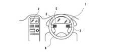
本実施形態のタッチ入力装置1の自動車内の設置状態を図1に、またハンドルの例として自動車のステアリングホイール4における設置位置を図2に示す。また、車載機器はカーナビゲーション装置2としている。First embodiment:
FIG. 1 shows an installation state of the
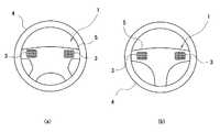
図2(a)で示すように、第1の検知手段または第2の検知手段としてのタッチセンサ3,3は、4本スポーク5のステアリングホイール4における左右両側であって、運転者がハンドルを握っている状態で、運転者の親指6a,6bが接することが可能な範囲に設置している。ステアリングホイール4のうち、運転者が運転操作中に無意識に接触することの少ないスポーク5にタッチセンサ3を配置することで、運転中に誤ってタッチセンサ3に接触し、誤操作することを防止することができる。
明細書または特許請求の範囲において「車両のハンドルを運転者が両手で握っている状態」とは、本実施形態においてはステアリングホイール4におけるいわゆる3時と9時の位置または10時と2時の位置のように進行方向に対して左右対称の位置に両手を置きステアリングホイール4を握っている状態をいうものとする。As shown in FIG. 2 (a), the
In the specification or claims, the “state where the driver holds the steering wheel of the vehicle with both hands” means, in the present embodiment, the so-called 3 o'clock and 9 o'clock positions or 10 o'clock and 2 o'clock positions on the
第1の検知手段であるタッチセンサ3や第2の検知手段であるタッチセンサ3としては、図3(a)で示すように、上下および左右方向にマトリクス状に連続して複数の検出部7を配置したタッチセンサ3aとすることができる。検出部7の配列方向に向けて親指6a,6bがスライド接触することで、時間差をつけて次々に隣接する各検出部7のON/OFFを切り替えることができる。例えば、上下方向に配列した検出部7に沿ってスライド操作を行うことで上下方向のスライド入力を行うことができる。また、左右方向に配列した検出部7に沿ってスライド操作を行うことで左右方向のスライド入力を行うことができる。 As shown in FIG. 3A, the
また、タッチセンサ3aでは、このような直線的なスライド操作だけではなく、運転者の親指6a,6bのタッチセンサ3上の位置をより正確に検出することができる。これは、マトリクス状に複数の検出部7が配置されているためであり、例えば液晶画面の画像等における特定の位置を指定することができ、かつその位置を拡大縮小するといった細かな操作が可能となる。 Further, the
タッチセンサ3としては、静電容量式タッチセンサや感圧式タッチセンサを好適に用いることができる。それぞれ、静電容量の変化または感圧ゴム等の電気抵抗の変化が生じることで検出部7のON/OFFが切り替わり、各車載機器へ出力される。静電容量式タッチセンサは高精度のタッチセンサ3とすることができる。また、感圧式タッチセンサは指で直接接触する操作だけではなく手袋をした指やタッチペン等による操作も可能であり、またより安価なタッチセンサ3とすることが可能である。 As the
(入力方法)
タッチ入力装置1を用いたタッチ入力方法を説明する。カーナビゲーション装置2の操作は、右の親指6aで右に配置したタッチセンサ3に対し検出部7の配列方向に沿ってスライド接触する。それと同時に左の親指6bで左に配置したタッチセンサ3に対し検出部7の配列方向に沿ってスライド接触する。(input method)
A touch input method using the
ここでのスライド接触は、第1に左右の親指6a,6bを同一方向に接触移動させることができる。例えば、左右の親指6a,6bを上下方向や左右方向等の同じ方向に向けて移動させながら接触することで、カーナビゲーション装置2の地図等の画像を指のスライド方向にスクロールするといった操作を直感的に行うことができる。あるいは、左右のタッチセンサ3,3のうち、いずれか一方にのみスライド接触する場合と比較して、双方に対して同一方向に同時にスライド接触する場合の方が、カーナビゲーション装置2のスクロール量を大きくすることができるといった操作方法も可能である。 In this sliding contact, the left and
第2に左右の親指6a,6bを同一方向ではなく反対方向(対称となる方向)に接触移動させるスライド接触を行うことができる。例えば、左の親指6bをステアリングホイール4の中心側から外周方向にスライドさせる一方で、右の親指6aをステアリングホイール4の中心側から外周方向にスライドさせる。こうした操作で画像が拡大する。また、左の親指6bをステアリングホイール4の外周方向から中心側にスライドさせる一方で、右の親指6aをステアリングホイール4の外周方向から中心側にスライドさせる。こうした操作で画像が縮小する。 Secondly, it is possible to perform a sliding contact in which the left and
左右の親指6a,6bを反対方向(対称となる方向)に動かす別の例は、左親指6bを上に移動させ右親指6aを下に移動させる。こうした操作でカーナビゲーション装置2の液晶画面上の画像等を右回転させたり右側に傾いた状態で表示されたりすることができる。また、左親指6bを下に右親指6aを上に移動させると、液晶画面上の画像等を左回転させたり左側に傾いた状態で表示されたりすることができる。 Another example of moving the left and
左右の親指6a,6bを「同時に」スライド接触する場合の同時は、人間の意識上で同時ととらえられればよいが、接触開始を同時と検出するための許容時間を設定することが好ましい。この許容時間は0.5秒以下であることが好ましい。0.5秒を超えると誤操作による入力が生じる可能性が高くなるためである。 The simultaneous contact with the left and
第1実施形態の変形例:
タッチセンサ3の設置位置はステアリングホイール4の形状に合わせて適宜変更することができる。図2(a)においては4本スポーク5のステアリングホイール4に設置する例を示したが、図2(b)で示すように3本スポーク5のステアリングホイール4であっても設置することができる。Modification of the first embodiment:
The installation position of the
タッチセンサ3における複数の検出部7の配置や大きさ、形状等も変更が可能である。例えば、ステアリングホイール4を運転者が両手で握っている状態での親指6a,6bの可動方向を考慮すると、やや斜めに上下左右を定めることがより好ましい。すなわち、上下方向は水平面に対し鉛直方向ではなく、図4の矢印Aで示すように、上方向は斜め内向きに、下方向は斜め外向きにする。また左右方向は、図4の矢印Bで示すように、親指6a,6bの付け根を支点に親指6a,6bの先端が円弧を描く方向とする。この場合、タッチセンサ3の複数の検出部7を、上記親指6a,6bの可動方向に沿って配列するために、図3(b)で示すように検出部7を斜め方向のマトリクス状に連続して配置したタッチセンサ3bとすることが好ましい。こうしたタッチセンサ3bを採用することで運転者による指の操作方向に対してより正確に画面上の操作を行わせることができる。タッチセンサ3bを用いれば、例えばタッチセンサ3aを斜めに傾けて設置しなくとも、親指の操作範囲により密接な検出部7とすることができる。 The arrangement, size, shape, and the like of the plurality of
あるいは、左の親指6bが触れるタッチセンサ3を図3(c)で示すような上下方向にのみ検出部7を重ねたタッチセンサ3cを用い、右の親指6aが触れるタッチセンサ3を図3(d)で示すような左右方向にのみ検出部7を重ねたタッチセンサ3dを用いることができる。
例えば、両親指6a,6bを同時に右方向にスライドさせる場合には、タッチセンサ3cで指の接触を検知し、タッチセンサ3dで右方向へのスライドを検知することができる。また、両親指6a,6bを同時に上方向にスライドさせる場合には、タッチセンサ3dで指の接触を検知し、タッチセンサ3cで上方向へのスライドを検知することができる。Alternatively, the
For example, when both thumbs 6a and 6b are simultaneously slid rightward, the
タッチセンサ3の検出部7の配列は図3(e)で示すように、中央に検出部7を一つ有し、さらにその上下左右に一つずつ検出部7を有するタッチセンサ3eとすることもできる。このタッチセンサ3eは、上下方向に3つ配列された検出部7に配列方向に沿ってスライド接触することで上下方向のタッチ入力が可能となる。また左右方向に3つ配列された検出部7に配列方向に沿ってスライド接触することで左右方向のタッチ入力が可能となる。従って、検出部7を計5つ備えるだけで、上下方向と左右方向という直行する二方向のタッチ入力が可能となるため、上述のマトリックス状に多くの検出部7を有するタッチセンサ3a,3b等と比較して、画面上の動きをシンプルにすることができる。また、製造が簡単でコストが低いタッチセンサ3eとすることができる。 As shown in FIG. 3E, the arrangement of the
種々のタッチセンサ3について説明したが、第1の検出部として機能するタッチセンサ3と第2の検出部として機能するタッチセンサ3は、検出部7の配置や形状等が同じであるタッチセンサ3を用いることが好ましい。また左右のタッチセンサ3の設置向きとしては、各タッチセンサ3の検出部7の配列方向が対称となるような向きで配置されることが好ましい。運転者が迷いを生じることなく感覚的に操作することができるためである。 Although
第2実施形態:
上記第1実施形態におけるタッチ入力方法はタッチセンサ3に対し、左右の親指6a,6bが、タッチセンサ3の検出部7の配列方向に沿って同時にスライド接触することで、カーナビゲーション装置2の操作をするものである。これに対し本実施形態のタッチ入力方法は、一方の親指6a,6bをタッチセンサ3に接触させた状態で、もう一方の親指6a,6bのみをスライド接触させるものとすることができる。これにより、スライド操作で左右の親指6a,6bの間隔が大きくなるとカーナビゲーション装置2の液晶画面の画像等が拡大し、逆に間隔が小さくなると縮小するといった使用方法も可能である。
または、一方の親指6a,6bをタッチセンサ3に接触させた状態で、もう一方の親指6a,6bのみを上下方向にスライド接触させることで、カーナビゲーション装置2の液晶画面の画像等が、接触のみだった親指6a,6b側を中心にして回転するといった使用方法も可能である。Second embodiment:
In the touch input method according to the first embodiment, the left and
Alternatively, with the one
但し、本実施形態におけるタッチセンサ3は、一方の親指が触れる第1の検知手段としてのタッチセンサ3と他方の親指が触れる第2の検知手段としてのタッチセンサ3とは、検出部7の配置や形状等が同じタッチセンサ3を用いる必要がある。すなわち、図3(c)で示すタッチセンサ3cと図3(d)で示すタッチセンサ3dとを組み合わせて用いることはできず、また、検出部7が一方向にのみ配列したタッチセンサ3c、3dを用いることはできない。スライド操作するどちらか一方の指のみで上下左右の移動を検知する必要があるからである。 However, the
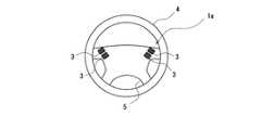
各実施形態の変形例:
第1および第2の検知手段としてタッチセンサ3をステアリングホイール4のスポーク5における左右両側に1つずつ設ける例を示したが、第1の検知手段や第2の検知手段は1つに限らず2以上のタッチセンサ3としても良い。すなわち、操作する車載装置の数や種類に応じて増加させることもできる。例えば図5で示すように、タッチセンサ3をスポーク5の左右に2つずつ設けたタッチ入力装置1aとすることができる。スポーク5の左右に1つずつ設けたタッチセンサ3で多様な車載装置の操作をすべて行うものとすれば、操作が煩雑になり運転者による誤操作が生じやすくなる。しかし、さらに多くのタッチセンサ3を設けてそれぞれで別々の車載装置を操作するものとすれば、そのような誤操作の発生を抑制することができる。また設置数が限定されないため、デザイン上、設計上の自由度を高めることもできる。このように3つ以上のタッチセンサ3を設ける場合にも、そのうち例えば2つのみに同時に接触した場合に入力が生じるものとしても良い。Modification of each embodiment:
As an example, the
タッチセンサ3には、入力以外の様々な機能を付加することができる。例えばタッチセンサ3に照光機能を持たせることで、入力時にタッチセンサ3を裏側から光らせるといった照光式タッチセンサとしても良い。照光式タッチセンサは、夜間や暗所で視認しやすいタッチセンサ3となる。 Various functions other than input can be added to the
上記各実施形態では、「同時」に入力する際の上限を0.5秒とした。しかし、上限は他の秒数であっても良く、また任意に変更可能としても良い。こうすることで、例えば運転者が高齢者である場合には1秒とするなど、運転者ごとに利用しやすいタッチセンサ3とすることができる。 In each of the embodiments described above, the upper limit when inputting “simultaneously” is set to 0.5 seconds. However, the upper limit may be another number of seconds or may be arbitrarily changed. By doing so, for example, when the driver is an elderly person, the
また、上記各実施形態ではステアリングホイール4を運転者が握っている状態で、タッチセンサ3の検出部7に親指6a,6bで接触を行う例を挙げたが、他の指で行うことも可能である。あるいは、指で直接接触する場合の他に、手袋等をはめたり、タッチペンを用いたりしても、静電容量変化を検知できれば静電容量式タッチセンサを用いることが可能である。これにより入力方法の自由度が高まり操作者の利便性を向上させることができる。 In each of the above embodiments, the example in which the
上記実施形態または変形例は本発明の一例であり、こうした形態に限定されるものではなく、本発明の趣旨に反しない他の任意の変更形態を含み、また上記以外の組合せ等も可能である。また、上記実施形態ではハンドルの例としてステアリングホイール4を挙げたが、自動二輪車や自転車等のハンドルに設置することも可能である。 The above-described embodiment or modification is an example of the present invention, and is not limited to such a form, includes other arbitrary modifications that do not contradict the gist of the present invention, and combinations other than the above are possible. . Moreover, although the
1 タッチ入力装置
1a 変形例のタッチ入力装置
2 カーナビゲーション装置
3 タッチセンサ
3a タッチセンサ
3b タッチセンサ
3c タッチセンサ
3d タッチセンサ
3e タッチセンサ
4 ステアリングホイール
5 スポーク
6a 右親指
6b 左親指
7 検出部
A 上下方向
B 左右方向DESCRIPTION OF
Claims (8)
Translated fromJapanese各検知手段は、各親指の可動範囲に沿って連続して配列した複数の検出部を有し、
第1の検知手段と第2の検知手段に同時に接触することで、車載機器の入力をするタッチ入力方法。In a state where the driver holds the vehicle handle with both hands, the first detection means is arranged in a range where one thumb of the driver contacts, and the second detection means is arranged in a range where the other thumb contacts. , A touch input method for inputting on-vehicle equipment by a touch operation to the detection means,
Each detection means has a plurality of detection units arranged continuously along the movable range of each thumb,
A touch input method for inputting on-vehicle equipment by simultaneously contacting the first detection means and the second detection means.
各検知手段は、各親指の可動範囲に沿って連続して配列した複数の検出部を有し、
第1の検知手段と第2の検知手段に同時に接触することで車載機器の入力がなされるタッチ入力装置。In a state where the driver holds the vehicle handle with both hands, the first detection means is arranged in a range where one thumb of the driver contacts, and the second detection means is arranged in a range where the other thumb contacts. , A touch input device for performing input of an in-vehicle device by a touch operation in contact with the detection means,
Each detection means has a plurality of detection units arranged continuously along the movable range of each thumb,
A touch input device that inputs an in-vehicle device by simultaneously contacting the first detection means and the second detection means.
Priority Applications (1)
| Application Number | Priority Date | Filing Date | Title |
|---|---|---|---|
| JP2013086515AJP2014211690A (en) | 2013-04-17 | 2013-04-17 | Touch input method and touch input device |
Applications Claiming Priority (1)
| Application Number | Priority Date | Filing Date | Title |
|---|---|---|---|
| JP2013086515AJP2014211690A (en) | 2013-04-17 | 2013-04-17 | Touch input method and touch input device |
Publications (1)
| Publication Number | Publication Date |
|---|---|
| JP2014211690Atrue JP2014211690A (en) | 2014-11-13 |
Family
ID=51931432
Family Applications (1)
| Application Number | Title | Priority Date | Filing Date |
|---|---|---|---|
| JP2013086515APendingJP2014211690A (en) | 2013-04-17 | 2013-04-17 | Touch input method and touch input device |
Country Status (1)
| Country | Link |
|---|---|
| JP (1) | JP2014211690A (en) |
Cited By (6)
| Publication number | Priority date | Publication date | Assignee | Title |
|---|---|---|---|---|
| WO2016079904A1 (en)* | 2014-11-19 | 2016-05-26 | パナソニックIpマネジメント株式会社 | Input device and input method therefor |
| DE102016218083A1 (en) | 2015-09-30 | 2017-03-30 | Fuji Jukogyo K.K. | Device for operating a device while steering |
| JP2017065509A (en)* | 2015-09-30 | 2017-04-06 | 富士重工業株式会社 | Steering handle for vehicle |
| JP2017065510A (en)* | 2015-09-30 | 2017-04-06 | 富士重工業株式会社 | Steering handle for vehicle |
| WO2017216868A1 (en)* | 2016-06-14 | 2017-12-21 | パイオニア株式会社 | Steering wheel, and electronic device |
| JP2019206335A (en)* | 2019-07-12 | 2019-12-05 | 株式会社Subaru | Steering handle for vehicle |
Citations (8)
| Publication number | Priority date | Publication date | Assignee | Title |
|---|---|---|---|---|
| JP2003167670A (en)* | 2001-12-04 | 2003-06-13 | Sharp Corp | Input device and portable device using the input device |
| JP2009132248A (en)* | 2007-11-29 | 2009-06-18 | Denso It Laboratory Inc | On-vehicle equipment operating device |
| JP2009298285A (en)* | 2008-06-12 | 2009-12-24 | Tokai Rika Co Ltd | Input device |
| US20110030502A1 (en)* | 2009-08-06 | 2011-02-10 | Lathrop William Brian | Motor vehicle |
| JP2011227854A (en)* | 2009-09-30 | 2011-11-10 | Aisin Aw Co Ltd | Information display device |
| JP2012078988A (en)* | 2010-09-30 | 2012-04-19 | Nippon Seiki Co Ltd | Display item selection device and display item selection system |
| JP2012177999A (en)* | 2011-02-25 | 2012-09-13 | Panasonic Corp | In-vehicle display system |
| WO2012169229A1 (en)* | 2011-06-09 | 2012-12-13 | 本田技研工業株式会社 | Vehicle operation device |
- 2013
- 2013-04-17JPJP2013086515Apatent/JP2014211690A/enactivePending
Patent Citations (8)
| Publication number | Priority date | Publication date | Assignee | Title |
|---|---|---|---|---|
| JP2003167670A (en)* | 2001-12-04 | 2003-06-13 | Sharp Corp | Input device and portable device using the input device |
| JP2009132248A (en)* | 2007-11-29 | 2009-06-18 | Denso It Laboratory Inc | On-vehicle equipment operating device |
| JP2009298285A (en)* | 2008-06-12 | 2009-12-24 | Tokai Rika Co Ltd | Input device |
| US20110030502A1 (en)* | 2009-08-06 | 2011-02-10 | Lathrop William Brian | Motor vehicle |
| JP2011227854A (en)* | 2009-09-30 | 2011-11-10 | Aisin Aw Co Ltd | Information display device |
| JP2012078988A (en)* | 2010-09-30 | 2012-04-19 | Nippon Seiki Co Ltd | Display item selection device and display item selection system |
| JP2012177999A (en)* | 2011-02-25 | 2012-09-13 | Panasonic Corp | In-vehicle display system |
| WO2012169229A1 (en)* | 2011-06-09 | 2012-12-13 | 本田技研工業株式会社 | Vehicle operation device |
Cited By (8)
| Publication number | Priority date | Publication date | Assignee | Title |
|---|---|---|---|---|
| WO2016079904A1 (en)* | 2014-11-19 | 2016-05-26 | パナソニックIpマネジメント株式会社 | Input device and input method therefor |
| JPWO2016079904A1 (en)* | 2014-11-19 | 2017-07-13 | パナソニックIpマネジメント株式会社 | Input device and input method thereof |
| DE102016218083A1 (en) | 2015-09-30 | 2017-03-30 | Fuji Jukogyo K.K. | Device for operating a device while steering |
| JP2017065509A (en)* | 2015-09-30 | 2017-04-06 | 富士重工業株式会社 | Steering handle for vehicle |
| JP2017065510A (en)* | 2015-09-30 | 2017-04-06 | 富士重工業株式会社 | Steering handle for vehicle |
| US10491850B2 (en) | 2015-09-30 | 2019-11-26 | Subaru Corporation | Apparatus for operating device upon steering |
| WO2017216868A1 (en)* | 2016-06-14 | 2017-12-21 | パイオニア株式会社 | Steering wheel, and electronic device |
| JP2019206335A (en)* | 2019-07-12 | 2019-12-05 | 株式会社Subaru | Steering handle for vehicle |
Similar Documents
| Publication | Publication Date | Title |
|---|---|---|
| US20190073122A1 (en) | System, apparatus and method for vehicle command and control | |
| JP5232889B2 (en) | Vehicle control device | |
| JP2014211690A (en) | Touch input method and touch input device | |
| JP5452566B2 (en) | Vehicle input device | |
| US20150015521A1 (en) | Gesture input operation processing device | |
| JP2014061761A (en) | On-vehicle equipment operating device | |
| JP6035828B2 (en) | Display operation device and display system | |
| KR20110076921A (en) | A display and manipulation system of a vehicle in which the user can influence the display of the display object and a method of operating the display and manipulation system | |
| CN102958756A (en) | Input device for vehicle and input method for vehicle | |
| US20180307405A1 (en) | Contextual vehicle user interface | |
| JP2016009300A (en) | Vehicle input device and vehicle cockpit module | |
| CN108108042A (en) | Display apparatus and its control method | |
| CN108693981B (en) | Vehicle input device | |
| JP5909048B2 (en) | In-vehicle input device | |
| JP7529380B2 (en) | Vehicle operation control device | |
| KR20120124518A (en) | Device for operating car communication control processor and method of thereof | |
| JP2018195134A (en) | On-vehicle information processing system | |
| JP6217535B2 (en) | Vehicle input device | |
| JP2012096670A (en) | Input device and input method | |
| JP2016052861A (en) | In-vehicle device operation device | |
| WO2016031152A1 (en) | Input interface for vehicle | |
| JP6429699B2 (en) | Vehicle input system | |
| JP6144027B2 (en) | In-vehicle device operation device | |
| JP2016115121A (en) | Vehicle operation apparatus | |
| JP2016099891A (en) | Display operation apparatus |
Legal Events
| Date | Code | Title | Description |
|---|---|---|---|
| A621 | Written request for application examination | Free format text:JAPANESE INTERMEDIATE CODE: A621 Effective date:20160412 | |
| A977 | Report on retrieval | Free format text:JAPANESE INTERMEDIATE CODE: A971007 Effective date:20170118 | |
| A131 | Notification of reasons for refusal | Free format text:JAPANESE INTERMEDIATE CODE: A131 Effective date:20170217 | |
| A521 | Request for written amendment filed | Free format text:JAPANESE INTERMEDIATE CODE: A523 Effective date:20170414 | |
| A131 | Notification of reasons for refusal | Free format text:JAPANESE INTERMEDIATE CODE: A131 Effective date:20170905 | |
| A02 | Decision of refusal | Free format text:JAPANESE INTERMEDIATE CODE: A02 Effective date:20180302 |