JP2014209278A - Field equipment - Google Patents
Field equipmentDownload PDFInfo
- Publication number
- JP2014209278A JP2014209278AJP2013085858AJP2013085858AJP2014209278AJP 2014209278 AJP2014209278 AJP 2014209278AJP 2013085858 AJP2013085858 AJP 2013085858AJP 2013085858 AJP2013085858 AJP 2013085858AJP 2014209278 AJP2014209278 AJP 2014209278A
- Authority
- JP
- Japan
- Prior art keywords
- output fluctuation
- field device
- abnormality
- pipe
- transmitter
- Prior art date
- Legal status (The legal status is an assumption and is not a legal conclusion. Google has not performed a legal analysis and makes no representation as to the accuracy of the status listed.)
- Pending
Links
Images


Classifications
- G—PHYSICS
- G05—CONTROLLING; REGULATING
- G05B—CONTROL OR REGULATING SYSTEMS IN GENERAL; FUNCTIONAL ELEMENTS OF SUCH SYSTEMS; MONITORING OR TESTING ARRANGEMENTS FOR SUCH SYSTEMS OR ELEMENTS
- G05B23/00—Testing or monitoring of control systems or parts thereof
- G05B23/02—Electric testing or monitoring
Landscapes
- Physics & Mathematics (AREA)
- General Physics & Mathematics (AREA)
- Engineering & Computer Science (AREA)
- Automation & Control Theory (AREA)
- Testing And Monitoring For Control Systems (AREA)
Abstract
Translated fromJapaneseDescription
Translated fromJapanese本発明は、フィールド機器に関し、詳しくは、駆動電源に関するものである。 The present invention relates to a field device, and more particularly to a drive power supply.
フィールド機器は、プロセス制御システムにおける現場設置計器として、いろいろなものが用いられている。 Various field devices are used as field-installed instruments in process control systems.
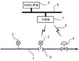
図7はプロセス制御システムの一例を示すブロック図である。図7において、プロセス流体が流れる配管1には、プロセス流体の流量を測定するために、オリフィスプレート2とオリフィスプレート2の上下流の圧力差を測定する差圧式伝送器3が設けられている。配管1には、この他、コントロールバルブの開閉を制御するバルブポジショナ4や、配管1を流れるプロセス流体の圧力、温度、流量などを測定して測定値を表示する現場指示計5が設けられている。 FIG. 7 is a block diagram illustrating an example of a process control system. In FIG. 7, a differential
差圧式伝送器3とバルブポジショナ4は、無線通信機能を有するものであり、無線6を介してゲートウェイなどの中継器7との間で信号の授受を行う。中継器7はイーサネット(登録商標)などのネットワーク8を介して分散制御システム(DCS)やプログラマプルロジックコントローラ(PLC)などの制御計算機9に接続されている。 The
制御計算機9は、中継器7を介して差圧式伝送器3やバルブポジショナ4との間で信号の授受を行うことにより、プロセス流体の測定値を取り込んだり、差圧式伝送器3やバルブポジショナ4を設定制御するための制御信号を送信したり、アラーム情報の監視などを行う。 The
現場指示計5は、測定現場において作業者が測定値を読み取り確認するために設けられるものであり、一般的には無線通信は行わない。常時電源が供給されていてプロセス流体を常時測定表示するものや、長大なパイプライン用などのように作業者が現場を巡回したときのみ電源を入れて測定表示させるものがある。 The on-site indicator 5 is provided for the operator to read and confirm the measurement value at the measurement site, and generally does not perform wireless communication. There are those that always supply power and always measure and display the process fluid, and others that turn on the power and measure and display only when the operator patrols the site, such as for a long pipeline.
なお、これら差圧式伝送器3とバルブポジショナ4および現場指示計5は、4〜20mA計装のような2線式線路による電源供給を受けないで、電池などの個別電源により駆動されるものである。 The
図8は、無線式伝送器として構成されている差圧式伝送器3の一例を示すブロック図である。配管1内を流れるプロセス流体の圧力、温度、流量などのプロセス量10はセンサモジュール11によって検出され電気信号に変換され、測定演算部12に入力される。 FIG. 8 is a block diagram illustrating an example of the
測定演算部12はマイクロプロセッサやRAMやEEPROMなどで構成されたものであり、センサモジュール11によって検出されたプロセス量10を変換補正してユーザーにより指定されるたとえば%値などのスケーリング値に換算するとともに、センサモジュール11などの周辺デバイスの制御や診断も行う。 The
無線通信部13は、図7に示す中継器7との間で無線6を介して信号の授受を行うものであり、測定演算部12で演算された計測量やスケーリング値や測定演算部12による伝送器の診断情報を中継器7に送信し、制御計算機9から送信される設定内容を測定演算部12に伝達する。なおこの無線通信部13には必要に応じて測定演算部12とは別に演算手段や記憶手段などが設けられることもある。 The
表示部14はたとえばバックライトを有するLCDで構成される外部指示計であり、測定演算部12で演算された計測量やスケーリング値を表示する。 The
電池電源モジュール15は装置を構成するセンサモジュール11、測定演算部12、無線通信部13、表示部14などの各部を駆動のための電源を供給するものであり、たとえばリチウム電池などの容量が大きくて放電末期までの電圧降下が少なく、自己放電も少なくて寿命の長いものが用いられる。 The battery
特許文献1には、電源として太陽電池パネルを設けたフィールド機器の構成が記載されている。
しかし、電池電源モジュール15として用いられる電池の寿命は、汎用的な価格や容量のものは数年程度であって、その都度電池の交換や充電が必要になる。 However, the battery used as the battery
ところが、フィールド機器の設置場所は、腐食性や爆発性ガスなどが存在する危険性雰囲気や高所など作業しにくい場所が多く、電池の交換には危険性に対する心理的圧迫なども含め作業者にかなりの負担を強いることになり、電池の保守作業はコスト増の要因になっている。 However, there are many places where field devices are installed that are difficult to work in, such as dangerous atmospheres or high places where corrosive or explosive gases exist, and battery replacement requires workers including psychological pressure on danger. This puts a considerable burden on the battery, and the maintenance work of the battery is a factor of cost increase.
また、電池の寿命対策として、間欠的に電源を供給して駆動するフィールド機器も提案されているが、配管1内を流れるプロセス流体が短時間に激しく変化する場合には、測定検出精度が低下したり、過大圧などの異常状態が発生した場合に見逃すおそれがあり、好ましくない。 In addition, field devices that are driven by intermittently supplying power have been proposed as measures against battery life. However, if the process fluid flowing in the
特許文献1に開示されているような太陽電池パネルを電源とするフィールド機器については、フィールド機器の設置場所には採光の不十分な所も多く、安定した発電量を確保するためには比較的広いスペースを必要とし、受光面が汚れやすい環境には不向きであることなどから、設置場所はかなり制限されることになる。 Regarding field devices that use a solar cell panel as a power source as disclosed in
本発明は、これらの従来の問題点に着目したものであり、その目的は、電源に関する保守作業が不要で、設置場所の制限も少ないフィールド機器を提供することにある。 The present invention focuses on these conventional problems, and an object of the present invention is to provide a field device that does not require maintenance work related to a power source and has few restrictions on installation locations.
このような課題を達成するために、本発明のうち請求項1記載の発明は、
上位システムと各種信号の授受を行うフィールド機器において、
配管内の測定流体の流れに基づくエネルギーを電気エネルギーに変換するエネルギー変換手段と、
前記エネルギー変換手段で変換された電気エネルギーを各部の駆動電源として蓄える二次電池と、
前記エネルギー変換手段で変換された電気エネルギーの出力変動を監視する出力変動監視手段と、
前記出力変動監視手段が電気エネルギーの出力変動の異常を検出することにより前記配管内の測定流体に異常が発生したことを外部に通知するアラーム手段、
を備えたことを特徴とする。In order to achieve such a problem, the invention according to
In field devices that exchange various signals with the host system,
Energy conversion means for converting energy based on the flow of the measurement fluid in the pipe into electrical energy;
A secondary battery that stores the electrical energy converted by the energy conversion means as a drive power source for each part;
Output fluctuation monitoring means for monitoring the output fluctuation of the electrical energy converted by the energy conversion means;
An alarm means for notifying the outside that an abnormality has occurred in the measured fluid in the pipe by the output fluctuation monitoring means detecting an abnormality in the output fluctuation of electrical energy;
It is provided with.
請求項2の発明は、請求項1記載のフィールド機器において、
前記フィールド機器は、
バックライトを有する表示器と、
前記出力変動監視手段が電気エネルギーの出力変動の異常を検出すると前記アラーム手段は前記バックライトの点滅を制御して前記配管内の測定流体に異常が発生したことを外部に通知することを特徴とする。The invention of
The field device is
A display having a backlight;
When the output fluctuation monitoring means detects an abnormality in output fluctuation of electrical energy, the alarm means controls the blinking of the backlight to notify the outside that an abnormality has occurred in the measured fluid in the pipe. To do.
請求項3の発明は、請求項2記載のフィールド機器において、
前記測定信号を上位に伝送する信号伝送機能と前記バックライトを点滅制御するバックライト機能は互いに独立していることを特徴とする。The invention according to
The signal transmission function for transmitting the measurement signal to the host and the backlight function for controlling the blinking of the backlight are independent of each other.
請求項4の発明は、請求項1から請求項3のいずれかに記載されたフィールド機器において、
前記上位システムとの各種信号の授受は有線伝送により行うことを特徴とする。The invention of
Various signals are exchanged with the host system by wired transmission.
請求項5の発明は、請求項1から請求項3のいずれかに記載されたフィールド機器において、
前記上位システムとの各種信号の授受は無線伝送により行うことを特徴とする。The invention according to claim 5 is the field device according to any one of
Various signals are exchanged with the host system by wireless transmission.
これらにより、電源に関する保守作業を大幅に省力化でき、必要な任意の場所に設置できる自由度の高いフィールド機器が実現できる。 As a result, maintenance work related to the power supply can be greatly saved, and a field device with a high degree of freedom that can be installed at any desired location can be realized.
以下、本発明について、図面を用いて詳細に説明する。図1は本発明の一実施例を示すブロック図であり、図7および図8と共通する部分には同一の符号を付けている。図1において、配管1の外壁には、測定流体の流れに基づくエネルギーを電気エネルギーに変換するエネルギー変換手段として、たとえばペルチェ素子のような発電素子16が設けられている。伝送器3は無線伝送形として形成されていて、無線伝送用のアンテナ17が設けられている。伝送器3は無線を介して上位システム18との間で測定データや設定値を含む各種情報の授受を行う。 Hereinafter, the present invention will be described in detail with reference to the drawings. FIG. 1 is a block diagram showing an embodiment of the present invention, and the same reference numerals are given to portions common to FIGS. In FIG. 1, a
配管1にたとえば高温の測定流体が流れることにより、発電素子16には配管1を介してその測定流体の温度に基づく熱エネルギーが伝達される。これにより、発電素子16の配管1の外壁取付面側における温度とその反対面側との温度差に応じた電力が発電され、伝送器3に出力供給される。 For example, when a high-temperature measurement fluid flows through the
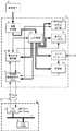
図2は、図1の伝送器3における内部回路の具体例を示すブロック図である。図2において、発電素子16の発電出力は受電充電部19を介して二次電池20を充電するように入力されるとともに、電力監視制御部21にも入力される。 FIG. 2 is a block diagram showing a specific example of an internal circuit in the
二次電池20は、図8の電池電源モジュール15と同様に、伝送器3を構成する内部回路の各部に駆動電力を供給する駆動電源として機能する。 The
電力監視制御部21は、受電充電部19を介して発電素子16の発電出力を監視するとともに、二次電池20の状態も監視する。 The power
発電素子16の発電出力が「ゼロ」になったり、所定の「設定値」や「時系列的変動特性」に対して大きな差異を生じた場合などは、発電素子16が設置されている場所の温度が何かの原因で大きく変化したと判断する。具体的には、配管1の外周を被覆している保温材の破損や、配管1の内部を流れる流体の漏洩などが考えられる。 When the power generation output of the
そこで、これらの事態が発生した場合には、電力監視制御部21は、たとえばCPUで構成される伝送器機能制御部22および無線通信部13を介して、図示しない上位システムに、重畳信号として、またはデジタル通信の場合には単独のコマンドとして、この伝送器3を含むプロセスに何らかの変化(異常)が発生していることを通知する。 Therefore, when these situations occur, the power
また、電力監視制御部21は、これらの異常状態が発生した場合には、同時に表示部14のバックライトを点灯または点滅させる駆動信号を出力してバックライトを点灯駆動する。現場作業者は、これらバックライトの点灯駆動により、異常状態になった伝送器を容易に発見できる。 In addition, when these abnormal states occur, the power
なお、これらの異常状態が発生した場合に、プロセス信号を上位システムに伝達する本来の機能には関係しない構成としておくことにより、たとえばプラントシャットダウンなどで一時的に配管が常温になった場合であっても伝送器のバックライトが消えるだけにとどめて出力信号への影響を回避できる。 Note that when these abnormal conditions occur, a configuration that does not relate to the original function of transmitting the process signal to the host system is used, for example, when the piping temporarily becomes room temperature due to a plant shutdown or the like. However, it is possible to avoid the influence on the output signal only by turning off the backlight of the transmitter.
また、伝送器自身に二次電池20を搭載することにより、発電素子からの電力を電池に充電できることから電池の交換周期を大幅に延長でき、前述のような一時的に発電素子16の発電ができなくなった場合でも、電池の残量電力が無くなるまでバックライトを点灯させることができる。 In addition, by installing the
また、伝送器自身に二次電池20を搭載したことにより、伝送器外部への電源供給も可能となり、伝送器の外部近傍に回転灯やブザーなどのアラーム出力部23を設置して、伝送器に異常が発生した場合にはこれらアラーム出力部23を二次電池20からの電源供給と駆動信号により駆動できる。 In addition, since the
また、伝送器機能制御部22として機能するCPUは、発電素子16が発電しない場合は決められた通常動作をするが、発電素子16からCPUにとって十分な電力が二次電池20から供給されている場合には、通常の電力では実行できないたとえばCPU内部演算クロック数の変更を行うことでたとえば自己診断などの高負荷な機能を動作させることが可能になり、プラント操業の効率化や、伝送器自身の情報の上位システムへの伝送などが実現できる。 Further, the CPU functioning as the transmitter
また、通常運転時にはバックライトは常時点灯とせず、何らかの信号入力時のみに点灯させるようにすることで、点灯させたいときの点灯可能時間の延長が可能となる。 In addition, during normal operation, the backlight is not always turned on, but is turned on only when some signal is input, so that it is possible to extend the turn-on time when it is desired to turn on the backlight.
また、たとえば電力監視制御部21で発電素子16からの発電量を計測することにより発電量の変化をプロセス流体の変化として解析することも可能であり、プラントの異常解析に用いることもできる。 Further, for example, by measuring the amount of power generated from the
図3は本発明の他の具体例を示すブロック図であり、図1と共通する部分には同一の符号を付けている。図3において、伝送器3は2線式伝送路24を介して上位システム18との間で測定データや設定値を含む各種情報の授受を行う。上位システム18はたとえば電源として直流電圧24Vを伝送器3に供給し、伝送器3は測定信号をたとえば直流電流4〜20mAに変換して上位システム18に伝送する。 FIG. 3 is a block diagram showing another specific example of the present invention, and the same reference numerals are given to portions common to FIG. In FIG. 3, the
図4は図1の伝送器3における内部回路の他の具体例を示すブロック図であり、図2と共通する部分には同一の符号を付けている。図2と図4の相違点は、図4では図2の伝送器機能制御部22に接続されていた無線通信部13を取り除き、伝送器機能制御部22と上位システム18側に設けられている信号変換部25とを2線式伝送路24を介して接続していることである。 FIG. 4 is a block diagram showing another specific example of the internal circuit in the
図4の構成によれば、無線伝送に代えて2線式伝送路24による有線伝送を行うことから、無線伝送の場合に想定される混信や傍受のおそれなどを根本的に解消できる。 According to the configuration of FIG. 4, wired transmission using the two-
さらに、電力監視制御部21で直流電圧24Vも監視し、たとえば断線など何らかの理由で伝送器3に電源が供給されなくなった場合でも、発電素子16によって発電された電力を使ってバックライト14を直接点灯させる構成とすることにより、伝送器3に電源が供給されなくなった状態であっても異常となった対象伝送器を現場作業者が容易に発見することができる。 Furthermore, the power
図5も本発明の他の実施例を示すブロック図であり、図4と共通する部分には同一の符号を付けている。図4と図5の相違点は、図5では図4の各ブロックに電源を供給するために設けられていた二次電池20を取り除き、受電充電部19から各ブロックに電源を直接供給していることである。発電素子16の発電電力量が十分に大きくて安定しているという条件が満たされれば、二次電池20を取り除くことができる。 FIG. 5 is also a block diagram showing another embodiment of the present invention, and the same reference numerals are given to the portions common to FIG. The difference between FIG. 4 and FIG. 5 is that the
図6も本発明の他の実施例を示すブロック図であり、図3と共通する部分には同一の符号を付けている。図6と図3の相違点は、図6では配管1の外壁に配管1の内部に流れる測定流体の温度を測定するための温度センサ25を設けていることである。 FIG. 6 is also a block diagram showing another embodiment of the present invention, and the same reference numerals are given to portions common to FIG. 6 differs from FIG. 3 in that a
図6の構成によれば、たとえば温度センサ25で測定するプロセスの温度と発電素子16の発電電力量との対応関係の理論値と実測値とを比較することにより、そのシステムについて自己診断を行うことができ、システムの故障発生を予見して適切な予防措置を講じることもできる。 According to the configuration of FIG. 6, for example, the system performs self-diagnosis by comparing the theoretical value and the actual measurement value of the correspondence relationship between the temperature of the process measured by the
以上説明したように、本発明に基づくフィールド機器によれば、電源に関する保守作業が不要で、設置場所の制限も少ないフィールド機器を実現できる。 As described above, according to the field device according to the present invention, it is possible to realize a field device that does not require maintenance work related to the power source and has few restrictions on the installation location.
1 配管
3 伝送器
14 表示部
16 発電素子
17 アンテナ
18 上位システム
19 受電充電部
20 二次電池
21 電力監視制御部
22 伝送器機能制御部
23 アラーム出力部
24 2線式伝送路
25 信号変換部DESCRIPTION OF
Claims (5)
Translated fromJapanese配管内の測定流体の流れに基づくエネルギーを電気エネルギーに変換するエネルギー変換手段と、
前記エネルギー変換手段で変換された電気エネルギーを各部の駆動電源として蓄える二次電池と、
前記エネルギー変換手段で変換された電気エネルギーの出力変動を監視する出力変動監視手段と、
前記出力変動監視手段が電気エネルギーの出力変動の異常を検出することにより前記配管内の測定流体に異常が発生したことを外部に通知するアラーム手段、
を備えたことを特徴とするフィールド機器。In field devices that exchange various signals with the host system,
Energy conversion means for converting energy based on the flow of the measurement fluid in the pipe into electrical energy;
A secondary battery that stores the electrical energy converted by the energy conversion means as a drive power source for each part;
Output fluctuation monitoring means for monitoring the output fluctuation of the electrical energy converted by the energy conversion means;
An alarm means for notifying the outside that an abnormality has occurred in the measured fluid in the pipe by the output fluctuation monitoring means detecting an abnormality in the output fluctuation of electrical energy;
Field device characterized by comprising
バックライトを有する表示器を備え、
前記出力変動監視手段が電気エネルギーの出力変動の異常を検出すると前記アラーム手段は前記バックライトの点滅を制御して前記配管内の測定流体に異常が発生したことを外部に通知することを特徴とする請求項1記載のフィールド機器。The field device is
Comprising a display with a backlight;
When the output fluctuation monitoring means detects an abnormality in output fluctuation of electrical energy, the alarm means controls the blinking of the backlight to notify the outside that an abnormality has occurred in the measured fluid in the pipe. The field device according to claim 1.
Priority Applications (1)
| Application Number | Priority Date | Filing Date | Title |
|---|---|---|---|
| JP2013085858AJP2014209278A (en) | 2013-04-16 | 2013-04-16 | Field equipment |
Applications Claiming Priority (1)
| Application Number | Priority Date | Filing Date | Title |
|---|---|---|---|
| JP2013085858AJP2014209278A (en) | 2013-04-16 | 2013-04-16 | Field equipment |
Publications (1)
| Publication Number | Publication Date |
|---|---|
| JP2014209278Atrue JP2014209278A (en) | 2014-11-06 |
Family
ID=51903478
Family Applications (1)
| Application Number | Title | Priority Date | Filing Date |
|---|---|---|---|
| JP2013085858APendingJP2014209278A (en) | 2013-04-16 | 2013-04-16 | Field equipment |
Country Status (1)
| Country | Link |
|---|---|
| JP (1) | JP2014209278A (en) |
Citations (7)
| Publication number | Priority date | Publication date | Assignee | Title |
|---|---|---|---|---|
| US5495769A (en)* | 1993-09-07 | 1996-03-05 | Rosemount Inc. | Multivariable transmitter |
| US20060116102A1 (en)* | 2004-05-21 | 2006-06-01 | Brown Gregory C | Power generation for process devices |
| JP2008500659A (en)* | 2004-05-21 | 2008-01-10 | ローズマウント インコーポレイテッド | Power supply for process field devices and wireless communication unit |
| JP2008301675A (en)* | 2007-06-04 | 2008-12-11 | Yokogawa Electric Corp | Field equipment |
| WO2009101714A1 (en)* | 2008-02-14 | 2009-08-20 | Mitsubishi Electric Corporation | Control center |
| JP2011520185A (en)* | 2008-04-22 | 2011-07-14 | ローズマウント インコーポレイテッド | Industrial process equipment using piezoelectric transducers |
| JP2012137428A (en)* | 2010-12-27 | 2012-07-19 | Asahi Glass Co Ltd | Piping monitoring system |
- 2013
- 2013-04-16JPJP2013085858Apatent/JP2014209278A/enactivePending
Patent Citations (7)
| Publication number | Priority date | Publication date | Assignee | Title |
|---|---|---|---|---|
| US5495769A (en)* | 1993-09-07 | 1996-03-05 | Rosemount Inc. | Multivariable transmitter |
| US20060116102A1 (en)* | 2004-05-21 | 2006-06-01 | Brown Gregory C | Power generation for process devices |
| JP2008500659A (en)* | 2004-05-21 | 2008-01-10 | ローズマウント インコーポレイテッド | Power supply for process field devices and wireless communication unit |
| JP2008301675A (en)* | 2007-06-04 | 2008-12-11 | Yokogawa Electric Corp | Field equipment |
| WO2009101714A1 (en)* | 2008-02-14 | 2009-08-20 | Mitsubishi Electric Corporation | Control center |
| JP2011520185A (en)* | 2008-04-22 | 2011-07-14 | ローズマウント インコーポレイテッド | Industrial process equipment using piezoelectric transducers |
| JP2012137428A (en)* | 2010-12-27 | 2012-07-19 | Asahi Glass Co Ltd | Piping monitoring system |
Similar Documents
| Publication | Publication Date | Title |
|---|---|---|
| JP5554328B2 (en) | RF adapter for field devices with intrinsically safe low voltage clamp circuit | |
| RU2372667C2 (en) | Diagnostic means of wireless field device for manufacturing process | |
| US9438331B2 (en) | System and method to monitor and control remote sensors and equipment | |
| EP2940388B1 (en) | Remote burner monitoring system | |
| US20120002605A1 (en) | Wireless field device | |
| CA2597145A1 (en) | Charging system for field devices | |
| US20110074601A1 (en) | Utility meter with flow rate sensitivity shut off | |
| EP1247036A1 (en) | System for acquiring data from a facility and method | |
| KR20170050625A (en) | REMOTE MONITORING SYSTEM WITH DATA LOGGER FOR IoT BASED PLANT UTILITY | |
| EP2710444B1 (en) | Process device with light change triggered display | |
| JP5057140B2 (en) | Field equipment | |
| KR101708762B1 (en) | Power monitoring system and power monitoring device | |
| US9440799B1 (en) | Conveying apparatus | |
| CN110426628A (en) | Transmitter and system for on-line testing gas density relay | |
| CN119491941A (en) | Intelligent gas safety valve and intelligent method for opening and closing the safety valve | |
| JP2014209278A (en) | Field equipment | |
| CN211718717U (en) | Integrated instrument system | |
| CN213332710U (en) | Displacement detection device for valve and valve | |
| JP2012257376A (en) | Substation monitoring system | |
| CN202933681U (en) | Temperature-pressure control system for high-pressure reaction kettle and high-pressure reaction kettle comprising temperature-pressure control system | |
| LU506994B1 (en) | Intelligent monitoring and control system for electric trace heating equipment | |
| JP2013120582A (en) | Wireless field apparatus | |
| CN203810365U (en) | Comprehensive control device and system of boiler system | |
| KR102698937B1 (en) | Wireless signal converter within flameproof enclosure | |
| JP2016145788A (en) | Power consumption management system for various devices |
Legal Events
| Date | Code | Title | Description |
|---|---|---|---|
| A621 | Written request for application examination | Free format text:JAPANESE INTERMEDIATE CODE: A621 Effective date:20151105 | |
| A131 | Notification of reasons for refusal | Free format text:JAPANESE INTERMEDIATE CODE: A131 Effective date:20160823 | |
| A977 | Report on retrieval | Free format text:JAPANESE INTERMEDIATE CODE: A971007 Effective date:20160824 | |
| A521 | Request for written amendment filed | Free format text:JAPANESE INTERMEDIATE CODE: A523 Effective date:20161004 | |
| A02 | Decision of refusal | Free format text:JAPANESE INTERMEDIATE CODE: A02 Effective date:20170314 |