JP2014208308A - Dental laser system using midrange gas pressure - Google Patents
Dental laser system using midrange gas pressureDownload PDFInfo
- Publication number
- JP2014208308A JP2014208308AJP2014161014AJP2014161014AJP2014208308AJP 2014208308 AJP2014208308 AJP 2014208308AJP 2014161014 AJP2014161014 AJP 2014161014AJP 2014161014 AJP2014161014 AJP 2014161014AJP 2014208308 AJP2014208308 AJP 2014208308A
- Authority
- JP
- Japan
- Prior art keywords
- laser
- gas
- torr
- item
- power source
- Prior art date
- Legal status (The legal status is an assumption and is not a legal conclusion. Google has not performed a legal analysis and makes no representation as to the accuracy of the status listed.)
- Pending
Links
- 210000001519tissueAnatomy0.000description12
- 238000000034methodMethods0.000description8
- 210000003298dental enamelAnatomy0.000description7
- 210000004268dentinAnatomy0.000description7
- 229910052588hydroxylapatiteInorganic materials0.000description7
- XYJRXVWERLGGKC-UHFFFAOYSA-Dpentacalcium;hydroxide;triphosphateChemical compound[OH-].[Ca+2].[Ca+2].[Ca+2].[Ca+2].[Ca+2].[O-]P([O-])([O-])=O.[O-]P([O-])([O-])=O.[O-]P([O-])([O-])=OXYJRXVWERLGGKC-UHFFFAOYSA-D0.000description7
- 238000005553drillingMethods0.000description3
- 239000010410layerSubstances0.000description3
- 230000004048modificationEffects0.000description3
- 238000012986modificationMethods0.000description3
- 210000004872soft tissueAnatomy0.000description3
- 238000010521absorption reactionMethods0.000description2
- 239000003990capacitorSubstances0.000description2
- 230000008878couplingEffects0.000description2
- 238000010168coupling processMethods0.000description2
- 238000005859coupling reactionMethods0.000description2
- 210000003074dental pulpAnatomy0.000description2
- 238000010438heat treatmentMethods0.000description2
- 239000000203mixtureSubstances0.000description2
- 230000003287optical effectEffects0.000description2
- BVKZGUZCCUSVTD-UHFFFAOYSA-LCarbonateChemical compound[O-]C([O-])=OBVKZGUZCCUSVTD-UHFFFAOYSA-L0.000description1
- 238000002679ablationMethods0.000description1
- 230000002411adverseEffects0.000description1
- 230000008901benefitEffects0.000description1
- 210000004204blood vesselAnatomy0.000description1
- 238000006243chemical reactionMethods0.000description1
- 208000002925dental cariesDiseases0.000description1
- 238000010586diagramMethods0.000description1
- 210000004195gingivaAnatomy0.000description1
- 229910052500inorganic mineralInorganic materials0.000description1
- 230000003993interactionEffects0.000description1
- 239000011707mineralSubstances0.000description1
- 210000005036nerveAnatomy0.000description1
- 230000008569processEffects0.000description1
- 239000011241protective layerSubstances0.000description1
- 238000002310reflectometryMethods0.000description1
- 230000035945sensitivityEffects0.000description1
Images

Classifications
- A—HUMAN NECESSITIES
- A61—MEDICAL OR VETERINARY SCIENCE; HYGIENE
- A61C—DENTISTRY; APPARATUS OR METHODS FOR ORAL OR DENTAL HYGIENE
- A61C1/00—Dental machines for boring or cutting ; General features of dental machines or apparatus, e.g. hand-piece design
- A61C1/0046—Dental lasers
- H—ELECTRICITY
- H01—ELECTRIC ELEMENTS
- H01S—DEVICES USING THE PROCESS OF LIGHT AMPLIFICATION BY STIMULATED EMISSION OF RADIATION [LASER] TO AMPLIFY OR GENERATE LIGHT; DEVICES USING STIMULATED EMISSION OF ELECTROMAGNETIC RADIATION IN WAVE RANGES OTHER THAN OPTICAL
- H01S3/00—Lasers, i.e. devices using stimulated emission of electromagnetic radiation in the infrared, visible or ultraviolet wave range
- H01S3/02—Constructional details
- H01S3/03—Constructional details of gas laser discharge tubes
- H—ELECTRICITY
- H01—ELECTRIC ELEMENTS
- H01S—DEVICES USING THE PROCESS OF LIGHT AMPLIFICATION BY STIMULATED EMISSION OF RADIATION [LASER] TO AMPLIFY OR GENERATE LIGHT; DEVICES USING STIMULATED EMISSION OF ELECTROMAGNETIC RADIATION IN WAVE RANGES OTHER THAN OPTICAL
- H01S3/00—Lasers, i.e. devices using stimulated emission of electromagnetic radiation in the infrared, visible or ultraviolet wave range
- H01S3/09—Processes or apparatus for excitation, e.g. pumping
- H01S3/097—Processes or apparatus for excitation, e.g. pumping by gas discharge of a gas laser
- H01S3/09702—Details of the driver electronics and electric discharge circuits
- H—ELECTRICITY
- H01—ELECTRIC ELEMENTS
- H01S—DEVICES USING THE PROCESS OF LIGHT AMPLIFICATION BY STIMULATED EMISSION OF RADIATION [LASER] TO AMPLIFY OR GENERATE LIGHT; DEVICES USING STIMULATED EMISSION OF ELECTROMAGNETIC RADIATION IN WAVE RANGES OTHER THAN OPTICAL
- H01S3/00—Lasers, i.e. devices using stimulated emission of electromagnetic radiation in the infrared, visible or ultraviolet wave range
- H01S3/14—Lasers, i.e. devices using stimulated emission of electromagnetic radiation in the infrared, visible or ultraviolet wave range characterised by the material used as the active medium
- H01S3/22—Gases
- H01S3/223—Gases the active gas being polyatomic, i.e. containing two or more atoms
- H01S3/2232—Carbon dioxide (CO2) or monoxide [CO]
- A—HUMAN NECESSITIES
- A61—MEDICAL OR VETERINARY SCIENCE; HYGIENE
- A61B—DIAGNOSIS; SURGERY; IDENTIFICATION
- A61B18/00—Surgical instruments, devices or methods for transferring non-mechanical forms of energy to or from the body
- A61B18/18—Surgical instruments, devices or methods for transferring non-mechanical forms of energy to or from the body by applying electromagnetic radiation, e.g. microwaves
- A61B18/20—Surgical instruments, devices or methods for transferring non-mechanical forms of energy to or from the body by applying electromagnetic radiation, e.g. microwaves using laser
- H—ELECTRICITY
- H01—ELECTRIC ELEMENTS
- H01S—DEVICES USING THE PROCESS OF LIGHT AMPLIFICATION BY STIMULATED EMISSION OF RADIATION [LASER] TO AMPLIFY OR GENERATE LIGHT; DEVICES USING STIMULATED EMISSION OF ELECTROMAGNETIC RADIATION IN WAVE RANGES OTHER THAN OPTICAL
- H01S3/00—Lasers, i.e. devices using stimulated emission of electromagnetic radiation in the infrared, visible or ultraviolet wave range
- H01S3/02—Constructional details
- H01S3/03—Constructional details of gas laser discharge tubes
- H01S3/0315—Waveguide lasers
Landscapes
- Physics & Mathematics (AREA)
- Electromagnetism (AREA)
- Optics & Photonics (AREA)
- Engineering & Computer Science (AREA)
- Health & Medical Sciences (AREA)
- Plasma & Fusion (AREA)
- Epidemiology (AREA)
- General Health & Medical Sciences (AREA)
- Oral & Maxillofacial Surgery (AREA)
- Dentistry (AREA)
- Chemical & Material Sciences (AREA)
- Life Sciences & Earth Sciences (AREA)
- Animal Behavior & Ethology (AREA)
- Chemical Kinetics & Catalysis (AREA)
- Public Health (AREA)
- Veterinary Medicine (AREA)
- Microelectronics & Electronic Packaging (AREA)
- Dental Tools And Instruments Or Auxiliary Dental Instruments (AREA)
- Laser Surgery Devices (AREA)
- Lasers (AREA)
- Surgical Instruments (AREA)
Abstract
Description
Translated fromJapanese (関連出願の引用)
本願は、共有に係る同時係属中の米国仮特許出願シリアル番号61/229,997号、タイトル「DENTAL LASER SYSTEM USING MIDRANGE
GAS PRSSURE」(2009年7月30日出願)について、35 U.S.C.§119(e)に基づいて優先権の利益を主張するものであり、同米国仮特許出願は、その全体が参照のため本明細書中に援用される。(Citation of related application)
This application is a co-pending US provisional patent application serial number 61 / 229,997, titled “DENTAL LASER SYSTEM USING MIDRANGE”.
For “GAS PRSSURE” (filed July 30, 2009), 35 U.S. Pat. S. C. §119 (e) claims priority benefit, the provisional patent application of which is incorporated herein by reference in its entirety.
(技術分野)
本発明は、腐敗を除去し、硬組織を切断、穿孔、または成形し、軟組織を除去および切断し、う食抑制のために硬組織を改変し、かつ硬組織表面の状態を改変して硬組織への付着を助けるためのシステムおよび方法に関する。本発明は、口腔組織、歯肉、および歯、例えば、ヒトまたは動物の口腔組織、歯肉、および歯に適用される。(Technical field)
The present invention removes spoilage, cuts, perforates, or molds hard tissue, removes and cuts soft tissue, modifies hard tissue to control caries, and modifies the condition of the hard tissue surface. It relates to a system and method for helping adherence to tissue. The present invention applies to oral tissues, gums and teeth, such as human or animal oral tissues, gums and teeth.
(背景)
歯は、3つの層を有する。最外層は、最も硬く、その歯の残りの部分に保護層を形成するエナメルである。歯の中央部または大部分は、象牙質で構成されており、最内層は歯髄である。エナメルおよび象牙質は、組成上類似しており、約85%鉱物、すなわち、炭酸ヒドロキシアパタイトであり、一方で、歯髄は、圧力および温度に敏感である血管および神経を含有する。エナメルおよび象牙質を穿孔、輪郭形成、または調整する本用途において、歯髄の温度感度が懸念される。摂氏5.5℃の温度上昇は、歯の歯髄の永久的な損傷につながる場合もある。(background)
The tooth has three layers. The outermost layer is the hardest enamel that forms a protective layer on the rest of the teeth. The central part or most of the tooth is composed of dentin, and the innermost layer is the pulp. Enamel and dentin are similar in composition and are approximately 85% mineral, ie, hydroxyapatite carbonate, while the pulp contains blood vessels and nerves that are sensitive to pressure and temperature. In this application for drilling, contouring, or adjusting enamel and dentin, the temperature sensitivity of the pulp is a concern. An increase in temperature of 5.5 degrees Celsius may lead to permanent damage to the dental pulp.
過去10〜15年にわたって、歯髄を加熱することなく、歯のエナメルおよび象牙質に、全て除去プロセスである、除去、穿孔、輪郭形成、または調整を行うことが可能なレーザパラメータを定義するための研究が行われてきた。理想的には、レーザパルスは、歯髄を加熱する象牙質に残存する最小の残留エネルギーでその塊をガスに変換して、エナメルおよび象牙質を蒸発させるべきである。 Over the past 10-15 years, to define laser parameters that can be removed, drilled, contoured, or adjusted, all in the removal process, to the tooth enamel and dentin without heating the pulp Research has been done. Ideally, the laser pulse should convert the mass to gas with minimal residual energy remaining in the dentin that heats the pulp, causing the enamel and dentin to evaporate.
歯科におけるレーザの使用がレーザの導入以来考慮されてきた。穿孔および切断するために用いられる歯科用レーザが最初の用途であった。高エネルギー密度パルスが最初に使用されたが、これらのパルスは、歯の歯髄または軟組織を損傷する可能性があったため、より低いエネルギーパルス構造が模索された。より低いピーク電力のエネルギーパルスで、より長いパルス時間が使用され、これは、歯のエナメルに有害に作用した。 The use of lasers in dentistry has been considered since the introduction of lasers. Dental lasers used for drilling and cutting were the first applications. High energy density pulses were first used, but lower energy pulse structures were sought because these pulses could damage the dental pulp or soft tissue of the teeth. With lower peak power energy pulses, longer pulse times were used, which adversely affected tooth enamel.
光結合効率を理解するために、紫外線から遠赤外にわたる種々のレーザ波長相互作用が模索された。2.7〜3.0マイクロメートルおよび9.3〜9.6μmの波長範囲である最大結合を有する光結合が重大であることが見出された。反射率が考慮される場合、9.3〜9.6マイクロメートルの範囲が、任意の他の波長範囲よりも最大3倍良好に結合することが見出された。 In order to understand the optical coupling efficiency, various laser wavelength interactions ranging from ultraviolet to far infrared were sought. It has been found that photocoupling with a maximum coupling that is in the wavelength range of 2.7 to 3.0 micrometers and 9.3 to 9.6 μm is critical. When reflectivity is considered, the 9.3-9.6 micrometer range has been found to couple up to 3 times better than any other wavelength range.
最も効率的な結合波長を同定して、硬組織を切除する時間および閾値が決定される必要があった。研究は、硬組織の熱緩和時間が、5mJ(ミリジュール)の閾値アブレーションエネルギーで、約1〜2マイクロ秒であることを示した。 It was necessary to identify the most efficient binding wavelength and to determine the time and threshold for ablating hard tissue. Studies have shown that the thermal relaxation time of hard tissue is about 1-2 microseconds with a threshold ablation energy of 5 mJ (millijoules).
マイクロ秒のパルス幅を有する9.3〜9.6マイクロメートルの波長範囲のレーザパルスおよび5〜15mJのパルスエネルギーの必要性を認識することにより、DC励起TEA(横方向に励起した大気)レーザが採用された。TEAレーザが非常に短いパルス長、すなわち、数百ナノ秒を有するため、TEAレーザは、長いパルス動作用に改変され、パルス波形を改変された。さらに、RF(無線周波数)CW(連続波)レーザが研究されたが、その最短パルス長はわずか50マイクロ秒であったため、パルスは、より短いパルス幅よりも硬組織を著しく加熱した。 By recognizing the need for laser pulses in the 9.3-9.6 micrometer wavelength range with a pulse width of microseconds and pulse energy of 5-15 mJ, a DC pumped TEA (laterally pumped atmosphere) laser Was adopted. Since the TEA laser has a very short pulse length, ie several hundred nanoseconds, the TEA laser was modified for long pulse operation and the pulse waveform was modified. In addition, RF (radio frequency) CW (continuous wave) lasers were studied, but their shortest pulse length was only 50 microseconds, so the pulse significantly heated the hard tissue rather than the shorter pulse width.
これまで、光学効率に対する最大のRFを探究するRF励起CO2CWレーザは、典型的には、70〜100トル(または約9,332〜13,332パスカル(Pa))で動作し、生成される最短のパルス長は、典型的には、50マイクロ秒である。先行技術で使用される標準のRF励起CO2レーザに対する典型的なガス圧力は、80トル(または約10,665Pa)である。大気圧で動作するCO2TEAレーザは、パルス長数百ナノ秒で、9.3〜9.6マイクロメートルパルスを生成する。TEAレーザは、概して、密封動作で動作せず、長い動作寿命または高いパルス繰り返し率を有さず、かつ包装するのに費用がかかる。最適なCO2レーザパルジングパラメータを生成するために「長パルス」TEAレーザを製造することができる一方で、TEAレーザは、RF励起レーザよりも大きく、かつより高価であり、したがって、寸法および費用が重大である歯科用レーザ用途との適合には理想的ではない。したがって、これまでの取り組みのいずれも、歯髄を加熱することなくエナメルおよび象牙質と効果的に協働するための商業的に許容される形態で、最適なパラメータの一式を生成していない。To date, RF-pumped CO2 CW lasers that explore the maximum RF for optical efficiency are typically generated and operated at 70-100 Torr (or about 9,332-13,332 Pascals (Pa)). The shortest pulse length is typically 50 microseconds. A typical gas pressure for a standard RF pumped CO2 laser used in the prior art is 80 Torr (or about 10,665 Pa). A CO2 TEA laser operating at atmospheric pressure produces 9.3-9.6 micrometer pulses with a pulse length of several hundred nanoseconds. TEA lasers generally do not operate in a sealed operation, do not have a long operational life or high pulse repetition rate, and are expensive to package. While “long pulse” TEA lasers can be manufactured to generate optimal CO2 laser pulsing parameters, TEA lasers are larger and more expensive than RF-pumped lasers, and therefore are dimensionally and costly It is not ideal for compatibility with dental laser applications where is critical. Thus, none of the previous efforts has produced an optimal set of parameters in a commercially acceptable form to effectively work with enamel and dentin without heating the pulp.
(概要)
本開示の一態様に従って、直流(DC)電源、DC電源に連結される無線周波数(RF)電源、約260〜600トル(または約34,700〜80,000Pa)の範囲の圧力のガスで充填されるCO2レーザ、およびレーザから患者に出力されるレーザ光エネルギーを操向するよう構成されるビーム送達システムを備える、CO2歯科用レーザシステムが提供される。(Overview)
In accordance with one aspect of the present disclosure, a direct current (DC) power source, a radio frequency (RF) power source coupled to the DC power source, and filled with a gas at a pressure in the range of about 260-600 Torr (or about 34,700-80,000 Pa) It is the CO2 laser, and the laser includes a beam delivery system configured to steer the laser beam energy output to the patient from the, CO2 dental laser system is provided.
いくつかの実施形態において、圧力は、例として、約280〜550トル(または約37,330〜73,327Pa)、約300〜500トル(または約39,996〜66,661Pa)、約320〜450トル(または約42,663〜59,995Pa)、約340〜400トル(または約45,329〜53,328Pa)の範囲であってもよい。 In some embodiments, the pressure is, by way of example, about 280-550 Torr (or about 37,330-73,327 Pa), about 300-500 Torr (or about 39,996-66,661 Pa), about 320- The range may be 450 torr (or about 42,663 to 59,995 Pa), about 340 to 400 torr (or about 45,329 to 53,328 Pa).
前述実施形態のうちのいずれかにおいて、レーザは、一般に平板共振器と称される、不安定導波管ハイブリッド共振器を含んでもよい。 In any of the foregoing embodiments, the laser may include an unstable waveguide hybrid resonator, commonly referred to as a plate resonator.
前述実施形態のうちのいずれかにおいて、レーザは、導波管共振器を含んでもよい。 In any of the foregoing embodiments, the laser may include a waveguide resonator.
前述実施形態のうちのいずれかにおいて、レーザは、12C(18O)2ガスで充填されてもよい。In any of the foregoing embodiments, the laser may be filled with12 C (18 O)2 gas.
前述実施形態のうちのいずれかにおいて、レーザは、12C(16O)2ガスで充填されてもよい。In any of the foregoing embodiments, the laser may be filled with12 C (16 O)2 gas.
前述実施形態のうちのいずれかにおいて、レーザ共振器鏡は、約9.3〜9.6マイクロメートルの範囲内の波長で優先的に共振するよう被覆されてもよい。 In any of the foregoing embodiments, the laser resonator mirror may be coated to preferentially resonate at a wavelength in the range of about 9.3 to 9.6 micrometers.
前述実施形態のうちのいずれかにおいて、DC電源は、高ピーク電力パルシングを支援するように、コンデンサバンクに連結される低出力の連続した電力部を含んでもよい。 In any of the foregoing embodiments, the DC power supply may include a low power continuous power section coupled to the capacitor bank to support high peak power pulsing.
前述実施形態のうちのいずれかにおいて、RF電源は、約40〜125MHzの範囲で動作してもよい。 In any of the foregoing embodiments, the RF power source may operate in the range of about 40-125 MHz.
前述実施形態のうちのいずれかにおいて、RF電源は、約0〜60%の範囲のデューティサイクルで、連続波(CW)から約25KHzの範囲で動作する一式の高ピーク電力パルシングRFトランジスタを含んでもよい。 In any of the foregoing embodiments, the RF power source may include a set of high peak power pulsing RF transistors that operate from a continuous wave (CW) to about 25 KHz with a duty cycle ranging from about 0 to 60%. Good.
前述実施形態のうちのいずれかにおいて、ビーム送達システムは、CO2レーザから出力される光エネルギーを操向する平面鏡または曲面鏡の組み合わせを含んでもよい。In any of the foregoing embodiments, the beam delivery system may include a combination of plane mirrors or curved mirrors that steer the light energy output from the CO2 laser.
前述実施形態のうちのいずれかにおいて、ビーム送達システムは、中空導波管であってもよい。 In any of the foregoing embodiments, the beam delivery system may be a hollow waveguide.
前述実施形態のうちのいずれかにおいて、CO2レーザは、パルスモードで動作し、約50マイクロ秒以下の上昇および下降時間を有するパルスでガスを出力してもよい。In any of the foregoing embodiments, the CO2 laser may operate in a pulse mode and output gas with pulses having rise and fall times of about 50 microseconds or less.
本発明の別の態様に従って、直流(DC)電源、DC電源に連結される無線周波数(RF)電源、約260〜600トル(または約34,700〜80,000Pa)の範囲の圧力のガスで充填されるCO2レーザ、およびCO2レーザから患者に出力されるレーザ光エネルギーを操向するよう構成されるビーム送達システムを備える、CO2歯科用レーザシステムが提供される。DC電源は、連続波(CW)DC部分およびパルスDC部分から成る。In accordance with another aspect of the invention, a direct current (DC) power source, a radio frequency (RF) power source coupled to a DC power source, with a gas at a pressure in the range of about 260-600 Torr (or about 34,700-80,000 Pa). filled the CO2 laser, and CO comprises a beam delivery system configured to steer the laser beam energy output from thesecond laser to a patient, CO2 dental laser system is provided. The DC power supply consists of a continuous wave (CW) DC portion and a pulsed DC portion.
いくつかの実施形態において、圧力は、例として、約280〜550トル(または約37,330〜73,327Pa)、約300〜500トル(または約39,996〜66,661Pa)、約320〜450トル(または約42,663〜59,995Pa)、約340〜400トル(または約45,329〜53,328Pa)の範囲であってもよい。 In some embodiments, the pressure is, by way of example, about 280-550 Torr (or about 37,330-73,327 Pa), about 300-500 Torr (or about 39,996-66,661 Pa), about 320- The range may be 450 torr (or about 42,663 to 59,995 Pa), about 340 to 400 torr (or about 45,329 to 53,328 Pa).
前述実施形態のうちのいずれかにおいて、DC部分は、CW印加のためにCO2レーザを作動するよう構成されてもよく、パルスDC部分は、パルジング印加のためにCO2レーザをピークエネルギーで作動するよう構成されてもよい。In any of the previous embodiments, the DC portion may be configured to operate the CO2 laser for CW application, and the pulsed DC portion operates the CO2 laser at peak energy for pulsing application. It may be configured to do.
前述実施形態のうちのいずれかにおいて、CO2レーザは、平板共振器を含んでもよい。In any of the previous embodiments, the CO2 laser may include a plate resonator.
前述実施形態のうちのいずれかにおいて、CO2レーザは、導波管共振器を含んでもよい。In any of the previous embodiments, the CO2 laser may include a waveguide resonator.
前述実施形態のうちのいずれかにおいて、ガスは、12C(18O)2ガスであってもよい。In any of the previous embodiments, the gas may be12 C (18 O)2 gas.
前述実施形態のうちのいずれかにおいて、ガスは、12C(16O)2ガスであってもよい。In any of the previous embodiments, the gas may be12 C (16 O)2 gas.
前述実施形態のうちのいずれかにおいて、CO2レーザは、パルスモードで動作し、9.3〜9.6マイクロメートルの波長ならびに約50マイクロ秒以下の上昇および下降時間を有する光エネルギーを出力してもよい。In any of the foregoing embodiments, the CO2 laser operates in a pulsed mode and outputs light energy having a wavelength of 9.3 to 9.6 micrometers and rise and fall times of about 50 microseconds or less. May be.
本発明の別の態様に従って、直流(DC)電源、DC電源に連結される無線周波数(RF)電源、約260〜600トル(または約34,700〜80,000Pa)の範囲の圧力のガスで充填されるCO2レーザ、およびCO2レーザから患者に出力されるレーザ光エネルギーを操向するよう構成されるビーム送達システムを備える、CO2歯科用レーザシステムが提供される。CO2レーザは、パルスモードで動作し、9.3〜9.6マイクロメートルの波長ならびに約50マイクロ秒以下の上昇および下降時間を有する光エネルギーを出力してもよい。In accordance with another aspect of the invention, a direct current (DC) power source, a radio frequency (RF) power source coupled to a DC power source, with a gas at a pressure in the range of about 260-600 Torr (or about 34,700-80,000 Pa). filled the CO2 laser, and CO comprises a beam delivery system configured to steer the laser beam energy output from thesecond laser to a patient, CO2 dental laser system is provided. The CO2 laser may operate in a pulsed mode and output light energy having a wavelength of 9.3 to 9.6 micrometers and rise and fall times of about 50 microseconds or less.
いくつかの実施形態において、圧力は、例として、約280〜550トル(または約37,330〜73,327Pa)、約300〜500トル(または約39,996〜66,661Pa)、約320〜450トル(または約42,663〜59,995Pa)、約340〜400トル(または約45,329〜53,328Pa)の範囲であってもよい。 In some embodiments, the pressure is, by way of example, about 280-550 Torr (or about 37,330-73,327 Pa), about 300-500 Torr (or about 39,996-66,661 Pa), about 320- The range may be 450 torr (or about 42,663 to 59,995 Pa), about 340 to 400 torr (or about 45,329 to 53,328 Pa).
本発明のさらに別の態様に従って、CO2歯科用レーザシステムからレーザ光エネルギーを出力する方法が提供される。方法は、直流(DC)電源を提供すること、DC電源に連結される無線周波数(RF)電源を提供すること、CO2レーザを、所定の圧力範囲(例えば、約260〜600トル(または約34,700〜80,000Pa))の圧力のガスで充填すること、およびビーム送達システムを用いて、CO2レーザから患者に出力されるレーザ光エネルギーを操向することを含む。In accordance with yet another aspect of the present invention, a method of outputting a laser light energy from the CO2 dental laser system is provided. The method includes providing a direct current (DC) power source, providing a radio frequency (RF) power source coupled to the DC power source, a CO2 laser over a predetermined pressure range (eg, about 260-600 Torr (or about be filled with a gas pressure of 34,700~80,000Pa)), and using a beam delivery system comprises steering the laser beam energy output from the CO2 laser to the patient.
いくつかの実施形態において、圧力は、例として、約280〜550トル(または約37,330〜73,327Pa)、約300〜500トル(または約39,996〜66,661Pa)、約320〜450トル(または約42,663〜59,995Pa)、約340〜400トル(または約45,329〜53,328Pa)の範囲であってもよい。
例えば、本願発明は以下の項目を提供する。
(項目1)
直流(DC)電源と、
前記DC電源に連結される無線周波数(RF)電源と、
約260〜600トルの範囲の圧力のガスで充填されるCO2レーザと、
前記CO2レーザから患者に出力されるレーザ光エネルギーを操向するよう構成されるビーム送達システムと
を含む、CO2歯科用レーザシステム。
(項目2)
前記CO2レーザは、平板共振器を含む、項目1に記載のシステム。
(項目3)
前記CO2レーザは、導波管共振器を含む、項目1に記載のシステム。
(項目4)
前記ガスは、12C(18O)2ガスである、項目1に記載のシステム。
(項目5)
前記ガスは、12C(16O)2ガスである、項目1に記載のシステム。
(項目6)
前記レーザは、約9.3〜9.6マイクロメートルの範囲内の波長で共振するよう被覆される一式の共振器鏡を含む、項目1に記載のシステム。
(項目7)
前記DC電源は、コンデンサバンクに連結される低出力の連続した電力部を含むことにより、高ピーク電力パルシングを支援する、項目1に記載のシステム。
(項目8)
前記RF電源は、約40〜125MHzの範囲内で動作するよう構成される、項目1に記載のシステム。
(項目9)
前記RF電源は、約0〜60%の範囲のデューティサイクルで、連続波(CW)から約25KHzの範囲で動作する一式の高ピーク電力パルシングRFトランジスタを含む、項目1に記載のシステム。
(項目10)
前記ビーム送達システムは、前記CO2レーザから出力される光エネルギーを操向するよう構成される平面鏡または曲面鏡の組み合わせを含む、項目1に記載のシステム。
(項目11)
前記ビーム送達システムは、中空導波管を含む、項目1に記載のシステム。
(項目12)
前記CO2レーザは、パルスモードで動作し、9.3〜9.6マイクロメートルの波長と、約50マイクロ秒以下の上昇および下降時間とを有する光エネルギーを出力する、項目1に記載のシステム。
(項目13)
CO2歯科用レーザシステムであって、
直流(DC)電源であって、連続波(CW)DC部分およびパルスDC部分から成るDC電源と、
前記DC電源に連結される無線周波数(RF)電源と、
約260〜600トルの範囲の圧力のガスで充填されるCO2レーザと、
前記CO2レーザから患者に出力されるレーザ光エネルギーを操向するよう構成されるビーム送達システムと
を含む、システム。
(項目14)
前記DC部分は、CW印加のために前記CO2レーザを作動するよう構成され、前記パルスDC部分は、パルジング印加のために前記CO2レーザをピークエネルギーで作動するよう構成される、項目13に記載のシステム。
(項目15)
前記CO2レーザは、平板共振器を含む、項目13に記載のシステム。
(項目16)
前記CO2レーザは、導波管共振器を含む、項目13に記載のシステム。
(項目17)
前記ガスは、12C(18O)2ガスである、項目13に記載のシステム。
(項目18)
前記ガスは、12C(16O)2ガスである、項目13に記載のシステム。
(項目19)
前記CO2レーザは、パルスモードで動作し、9.3〜9.6マイクロメートルのエネルギーと、約2マイクロ秒以下の上昇および下降時間とを有するパルスで前記ガスを出力する、項目13に記載のシステム。
(項目20)
直流(DC)電源と、
前記DC電源に連結される無線周波数(RF)電源と、
約260〜600トルの範囲の圧力のガスで充填されるCO2レーザと、
前記CO2レーザから患者に出力されるレーザ光エネルギーを操向するよう構成されるビーム送達システムと
を含み、
前記CO2レーザは、パルスモードで動作し、9.3〜9.6マイクロメートルのエネルギーと、約2マイクロ秒以下の上昇および下降時間とを有するパルスで前記ガスを出力する、CO2歯科用レーザシステム。
(項目21)
CO2歯科用レーザシステムからレーザ光エネルギーを出力する方法であって、
直流(DC)電源を提供することと、
前記DC電源に連結される無線周波数(RF)電源を提供することと、
CO2レーザを約260〜600トルの範囲の圧力のガスで充填することと、
ビーム送達システムを用いて、前記CO2レーザから患者に出力される前記レーザ光エネルギーを操向することと
を含む、方法。In some embodiments, the pressure is, by way of example, about 280-550 Torr (or about 37,330-73,327 Pa), about 300-500 Torr (or about 39,996-66,661 Pa), about 320- The range may be 450 torr (or about 42,663 to 59,995 Pa), about 340 to 400 torr (or about 45,329 to 53,328 Pa).
For example, the present invention provides the following items.
(Item 1)
A direct current (DC) power supply;
A radio frequency (RF) power source coupled to the DC power source;
A CO2laserfilled with a gas at a pressure in the range of about 260-600 Torr;
Abeam delivery system configured to steer laser light energy output from theCO2laser to a patient;
CO2dental laser systemcomprising:
(Item 2)
The CO2laser comprises a plate resonator, according to claim 1 system.
(Item 3)
The system of claim 1,wherein the CO2laser comprises a waveguide resonator.
(Item 4)
The system according to item 1,wherein the gas is12C (18O)2gas.
(Item 5)
The system according to item 1,wherein the gas is12C (16O)2gas.
(Item 6)
The system of claim 1, wherein the laser includes a set of resonator mirrors that are coated to resonate at a wavelength in the range of about 9.3 to 9.6 micrometers.
(Item 7)
The system of claim 1, wherein the DC power source includes a low power continuous power section coupled to a capacitor bank to support high peak power pulsing.
(Item 8)
The system of claim 1, wherein the RF power source is configured to operate within a range of approximately 40-125 MHz.
(Item 9)
The system of claim 1, wherein the RF power source includes a set of high peak power pulsing RF transistors operating in a range from continuous wave (CW) to about 25 KHz, with a duty cycle ranging from about 0 to 60%.
(Item 10)
It said beam delivery systemcomprisesa combination ofthe CO2planar mirror configured to steer the light energy output from the laser or curved mirror system of claim 1.
(Item 11)
The system of claim 1, wherein the beam delivery system comprises a hollow waveguide.
(Item 12)
The system of claim 1, wherein the CO2laser operates in a pulsed mode and outputs light energy having a wavelength of 9.3 to 9.6 micrometers and rise and fall times of about 50 microseconds or less. .
(Item 13)
A CO2dental laser system,
A direct current (DC) power supply comprising a continuous wave (CW) DC portion and a pulsed DC portion;
A radio frequency (RF) power source coupled to the DC power source;
A CO2laserfilled with a gas at a pressure in the range of about 260-600 Torr;
Abeam delivery system configured to steer laser light energy output from theCO2laser to a patient;
Including the system.
(Item 14)
Item 13wherein the DC portion is configured to operate theCO2laserfor CW application,and the pulsed DC portion is configured to operate the CO2laser at peak energyfor pulsing application.The described system.
(Item 15)
The CO2laser comprises a plate resonator, according to claim 13 system.
(Item 16)
The system according tothe CO2laser comprising a waveguide resonator, item 13.
(Item 17)
14. The system according to item 13,wherein the gas is12C (18O)2gas.
(Item 18)
14. The system according to item 13,wherein the gas is12C (16O)2gas.
(Item 19)
The CO2laser operates in pulsed mode, and outputs the gas in pulses having an energy of 9.3 to 9.6 micrometers, and a rise of less than about 2 microseconds and fall times, claim 13 System.
(Item 20)
A direct current (DC) power supply;
A radio frequency (RF) power source coupled to the DC power source;
A CO2laserfilled with a gas at a pressure in the range of about 260-600 Torr;
Abeam delivery system configured to steer laser light energy output from theCO2laser to a patient;
Including
The CO2laser operates in pulsed mode, and the energy of 9.3 to 9.6 micrometers, and outputs the gas in pulses having a rise of no more than about 2 microseconds and fall times, CO2dental Laser system.
(Item 21)
A method of outputting laser light energy from aCO2dental laser system comprising:
Providing a direct current (DC) power source;
Providing a radio frequency (RF) power source coupled to the DC power source;
Filling theCO2laser with a gas at a pressure in the range of about 260-600 Torr;
Steering the laser light energy output from theCO2laser to a patientusing a beam delivery system;
Including the method.
本発明は、添付された図面および添付の詳細記述の視点からより明らかになる。ここで示される実施形態は、一例として提供され、限定を意図せず、類似の参照番号は、同一または同様の要素を指す。図面は、必ずしも原寸に比例しておらず、その代わりに、本発明の態様を説明する際に強調されている。
(好適な実施形態の詳細な説明)
以下、本発明の態様は、添付される図面を参照して、それに従って例示的実施形態を説明することにより記述される。これらの実施形態を説明する際、周知のアイテム、機能、または構造の詳細記述は、典型的には、簡潔さのために省略される。(Detailed description of preferred embodiments)
Aspects of the present invention will now be described by describing exemplary embodiments accordingly with reference to the accompanying drawings. In describing these embodiments, detailed descriptions of well-known items, functions, or structures are typically omitted for the sake of brevity.
要素が別の要素の「上に存在する」か、あるいは別の要素に「接続される」または「連結される」と見なされるとき、それは、他の要素の上に直接存在するか、他の要素に接続されるか、あるいは連結されてもよく、または介在要素が存在してもよいことを理解されたい。対照的に、要素が別の要素の「上に直接存在する」、「直接接続される」、または「直接連結される」とき、介在要素は存在しない。要素間の関係を説明するために用いられる他の単語は、類似の形態で解釈されるべきである(例えば、「〜の間に」対「直接的に〜の間に」、「隣接した」対「直接的に隣接した」等)。 When an element is “present on” another element, or considered “connected” or “coupled” to another element, it may be directly on top of the other element, It should be understood that there may be intervening elements that may be connected to or coupled to the elements. In contrast, when an element is “directly on”, “directly connected”, or “directly connected” to another element, there are no intervening elements present. Other words used to describe the relationship between elements should be interpreted in a similar manner (eg, “between” vs. “directly between”, “adjacent”) Vs. “directly adjacent” etc.).
本明細書で使用される専門用語は、特定の実施形態を説明することのみを目的としており、本発明を限定するよう意図されない。本明細書で使用される、単数形「ある(a)」、「ある(an)」、「その(the)」は、別途文脈が明確に示さない限り、複数形も含むよう意図される。「備える(comprise)」、「備える(comprising)」、「含む(include)」、および/または「含む(including)」という用語は、本明細書で使用されるとき、規定の特性、ステップ、動作、要素、および/または成分の存在を特定するが、1つ以上の他の特性、ステップ、動作、要素、成分、および/またはそれらの群の存在または追加を除外しないことがさらに理解される。 The terminology used herein is for the purpose of describing particular embodiments only and is not intended to be limiting of the invention. As used herein, the singular forms “a”, “an”, “the” are intended to include the plural forms as well, unless the context clearly indicates otherwise. The terms “comprising”, “comprising”, “including”, and / or “including”, as used herein, are defined characteristics, steps, operations, It is further understood that the presence of elements, elements, and / or components is specified but does not exclude the presence or addition of one or more other characteristics, steps, operations, elements, components, and / or groups thereof.
歯科用レーザシステムに関して、ヒドロキシアパタイトの極大吸収を有する波長は、9.3〜9.6マイクロメートルの範囲であり、ヒドロキシアパタイトの熱緩和時間は、9.3〜9.6μmの波長範囲で最大2マイクロ秒であると決定された。したがって、ヒドロキシアパタイトを除去するための理想的なパルスパラメータは、50マイクロ秒未満の形態で、9.3〜9.6マイクロメートルのエネルギーであると思われる。好ましい実施形態に従って、50マイクロ秒未満の形態で、9.3〜9.6μmの波長エネルギーを用いてヒドロキシアパタイトを除去するためのパルスパラメータを有するビームを生成するレーザが提供される。 For dental laser systems, the wavelength having the maximum absorption of hydroxyapatite is in the range of 9.3 to 9.6 micrometers, and the thermal relaxation time of hydroxyapatite is maximum in the wavelength range of 9.3 to 9.6 μm. It was determined to be 2 microseconds. Thus, the ideal pulse parameter for removing hydroxyapatite appears to be an energy of 9.3 to 9.6 micrometers in a form less than 50 microseconds. In accordance with a preferred embodiment, a laser is provided that generates a beam having a pulse parameter for removing hydroxyapatite using a wavelength energy of 9.3 to 9.6 μm in a form of less than 50 microseconds.
9.3〜9.6μmのエネルギーは、12C(18O)2のレーザガス混合物、波長選択共振器光学、より高価な空洞間波長デバイス、またはそれら3つの組み合わせを有するCO2レーザを用いて生成される。本発明に従って、50マイクロ秒パルスは、速いパルス上昇および下降時間で生成され、これはレーザガス圧力によりもたらされる。50マイクロ秒以下のパルス長を生成するために、少なくとも約260トル(または約34,663Pa)のガス圧力を用いる。Energy from 9.3 to 9.6 μm is generated using a CO2 laser with a12 C (18 O)2 laser gas mixture, wavelength selective resonator optics, a more expensive intercavity wavelength device, or a combination of the three Is done. In accordance with the present invention, 50 microsecond pulses are generated with fast pulse rise and fall times, which is caused by the laser gas pressure. A gas pressure of at least about 260 Torr (or about 34,663 Pa) is used to generate a pulse length of 50 microseconds or less.
好ましい実施形態に従って、CO2ガスレーザは、導波管または平板共振器形態のいずれかにおいて、約260トル〜600トル(または約34,700〜80,000Pa)の範囲のガスで充填され、これは、全ての歯科用途における使用のためにRF励起される。約260〜600トル(または約34,700〜80,000Pa)の範囲が多くの歯科用途において好ましくあり得る。導波管および平板共振器が当分野で一般的に既知であるため、これらは、本明細書で詳細に説明されない。According to a preferred embodiment, CO2 gas laser is any one of a waveguide or a flat resonator forms, filled with the gas in the range of about 260 torr to 600 torr (or about 34,700~80,000Pa), which RF excited for use in all dental applications. A range of about 260-600 Torr (or about 34,700-80,000 Pa) may be preferred for many dental applications. Since waveguides and plate resonators are generally known in the art, they will not be described in detail herein.
いくつかの実施形態において、圧力は、例として、約280〜550トル(または約37,330〜73,327Pa)、約300〜500トル(または約39,996〜66,661Pa)、約320〜450トル(または約42,663〜59,995Pa)、約340〜400トル(または約45,329〜53,328Pa)の範囲であってもよい。 In some embodiments, the pressure is, by way of example, about 280-550 Torr (or about 37,330-73,327 Pa), about 300-500 Torr (or about 39,996-66,661 Pa), about 320- The range may be 450 torr (or about 42,663 to 59,995 Pa), about 340 to 400 torr (or about 45,329 to 53,328 Pa).
レーザは、切断および穿孔用途のために、それぞれ、CWまたはパルスモードで動作されてもよい。DCおよびRF電源は、高ピーク電力パルス動作を支援しながら、低出力のCW動作を助けるよう構成される。レーザ出力は、光エネルギーを患者に送達するために、ビーム送達システムに連結される。レーザは、9.3〜9.6μmのエネルギー波長に、信頼性に優れた小型パッケージ内において、高速パルス上昇および下降時間(例えば、約50マイクロ秒以下、好ましくは、20マイクロ秒以下)、密封動作、高い繰り返し率を提供する。 The laser may be operated in CW or pulsed mode for cutting and drilling applications, respectively. The DC and RF power supplies are configured to assist low power CW operation while supporting high peak power pulse operation. The laser output is coupled to a beam delivery system for delivering light energy to the patient. The laser has an energy wavelength of 9.3 to 9.6 μm, fast pulse rise and fall times (eg, less than about 50 microseconds, preferably less than 20 microseconds), sealed in a small reliable package Provides operation, high repetition rate.
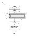
図1は、本発明の態様に従って、歯科用レーザシステム100の実施形態を示す。図1の実施形態において、AC入力電力(図示されず)として整流するDC電源10が提供される。好ましい実施形態において、DC電源10は、連続波(CW)DC部分12およびパルスDC部分14から成る。DC部分12は、軟組織切断等のCW印加のためにレーザを作動するよう寸法決めされ、ピーク電力DC部分14は、硬組織改変等のパルジング印加のためにピークエネルギーを供給する。 FIG. 1 illustrates an embodiment of a
アイテム20は、40〜125MHzの範囲のDCエネルギーのRFエネルギーへの変換のための無線周波数(RF)電源である。アイテム30は、出力カプラ32を介する、入力としてRFエネルギーを有し、出力として9.3〜9.6マイクロメートルの光エネルギーを有するCO2レーザである。また、アイテム40は、レーザから患者の口を表すアイテム50に光エネルギーを送達するビーム送達装置である。
本実施形態におけるCO2レーザ30は、後方鏡34およびレーザ放電領域36を含む。鏡34は、レーザ放電領域36を通して光エネルギーを配向する。出力カプラ32は、レーザから出てビームに連結する。この場合、レーザは、ガスレーザであるため、出力カプラは、レーザガスを放出することなく、レーザから出てビームに連結する。CO2レーザ30は、約260〜約600トル(または約34,700〜80,000Pa)の範囲の圧力のガスで充填されるレーザガス圧力容器38も含む。The CO2 laser 30 in the present embodiment includes a
出力レーザエネルギーがビーム送達装置40に提供され、その後、患者の口等の標的に配向されてもよい。本実施形態において、ビーム送達装置40は、CO2レーザから出力される光エネルギーを操向するよう構成される平面鏡または曲面鏡の組み合わせを含んでもよい。Output laser energy may be provided to the
本例示的構成において、歯科用レーザシステム100は、歯肉および口腔組織の切断のための低出力、例えば、10ワット未満のCW動作、ならびに例えば、1〜50マイクロ秒パルス幅で5mJ超のパルスエネルギーの高ピーク電力パルシング動作の双方で、最大10KHzで動作してもよい。CO2レーザ30は、9〜11μmの波長で動作してもよい。レーザシステム100は、好ましくは、理想的な吸収波長で、歯硬組織のヒドロキシアパタイトに高ピーク電力パルシング動作を提供する。パルス幅およびパルスエネルギーは、理想的には、ヒドロキシアパタイトを切除するのに適しており、最大10KHzでの動作中でさえ、非常にわずかの余熱しか歯に残さず、歯髄を損傷しない。In this exemplary configuration, the
図2は、CO2歯科用レーザシステムからレーザ光エネルギーを出力する方法の実施形態である。方法200は、ステップ210で直流(DC)電源を提供すること、ステップ220でDC電源に連結される無線周波数(RF)電源を提供すること、ステップ230で所定の圧力範囲(例えば、約260〜600トル(または約34,700〜80,000Pa))の圧力のガスでCO2レーザを充填すること、およびビーム送達システム240を用いて、CO2レーザから患者に出力されるレーザ光エネルギーを操向することを含む。FIG. 2 is an embodiment of a method for outputting laser light energy from a CO2 dental laser system. The
前述では最善の様式および/または他の好ましい実施形態であると見なされるものを説明したが、その中で種々の改変が行われてもよく、本発明または複数の発明が種々の形態および実施形態において実施される場合もあり、それらは多数の用途において適用される場合もあり、それらのほんの一部が本明細書に記載されたことを理解されたい。例えば、説明されるレーザおよびレーザシステムを他の(非歯科用)用途で使用することが可能である。以下の特許請求の範囲により、それぞれの特許請求の範囲内に収まる全ての改変および変形を含む、文字通り説明されるもの、およびそれと同等のもの全てを請求することが意図される。
While the foregoing describes what is considered to be the best mode and / or other preferred embodiments, various modifications may be made therein, and the invention or inventions may vary in various forms and embodiments. It is to be understood that only a few of them have been described herein, as they may be implemented in and may be applied in numerous applications. For example, the described lasers and laser systems can be used in other (non-dental) applications. It is intended by the following claims to claim all that are described literally, and all equivalents, including all modifications and variations that fall within the scope of each claim.
Claims (1)
Translated fromJapaneseApplications Claiming Priority (2)
| Application Number | Priority Date | Filing Date | Title |
|---|---|---|---|
| US22999709P | 2009-07-30 | 2009-07-30 | |
| US61/229,997 | 2009-07-30 |
Related Parent Applications (1)
| Application Number | Title | Priority Date | Filing Date |
|---|---|---|---|
| JP2012523100ADivisionJP5866118B2 (en) | 2009-07-30 | 2010-07-30 | Dental laser system using medium range gas pressure |
Publications (1)
| Publication Number | Publication Date |
|---|---|
| JP2014208308Atrue JP2014208308A (en) | 2014-11-06 |
Family
ID=43527379
Family Applications (2)
| Application Number | Title | Priority Date | Filing Date |
|---|---|---|---|
| JP2012523100AActiveJP5866118B2 (en) | 2009-07-30 | 2010-07-30 | Dental laser system using medium range gas pressure |
| JP2014161014APendingJP2014208308A (en) | 2009-07-30 | 2014-08-07 | Dental laser system using midrange gas pressure |
Family Applications Before (1)
| Application Number | Title | Priority Date | Filing Date |
|---|---|---|---|
| JP2012523100AActiveJP5866118B2 (en) | 2009-07-30 | 2010-07-30 | Dental laser system using medium range gas pressure |
Country Status (6)
| Country | Link |
|---|---|
| US (3) | US8251984B2 (en) |
| EP (1) | EP2459115A4 (en) |
| JP (2) | JP5866118B2 (en) |
| BR (1) | BR112012006892A2 (en) |
| CA (1) | CA2769448C (en) |
| WO (1) | WO2011014802A2 (en) |
Families Citing this family (21)
| Publication number | Priority date | Publication date | Assignee | Title |
|---|---|---|---|---|
| EP2459115A4 (en) | 2009-07-30 | 2017-03-15 | Nathan Paul Monty | Dental laser system using midrange gas pressure |
| ES2620231T3 (en)* | 2011-02-02 | 2017-06-28 | Convergent Dental | Dental laser system |
| US9622833B2 (en) | 2011-09-02 | 2017-04-18 | Convergent Dental, Inc. | Laser based computer controlled dental preparation system |
| WO2013173334A2 (en) | 2012-05-14 | 2013-11-21 | Convergent Dental, Inc. | Apparatus and method for controlled fluid cooling during laser based dental treatments |
| US10188519B2 (en)* | 2013-03-15 | 2019-01-29 | University Of North Texas | Laser-assisted machining (LAM) of hard tissues and bones |
| JP6546591B2 (en)* | 2013-11-27 | 2019-07-17 | コンバージェント デンタル, インコーポレイテッド | System and method for grounding or insulation of dental handpieces |
| EP3073952B1 (en)* | 2013-11-27 | 2020-01-08 | Convergent Dental, Inc. | Systems for protection of optical system of laser-based apparatus |
| US20150153485A1 (en) | 2013-11-27 | 2015-06-04 | Convergent Dental, Inc. | Coated mirrors for use in laser-based dental treatment systems and methods of making such mirrors |
| US20150238261A1 (en) | 2014-02-27 | 2015-08-27 | Convergent Dental, Inc. | System and method for treatment using a laser beam delivered via an optical fiber |
| US11291522B2 (en)* | 2014-11-26 | 2022-04-05 | Convergent Dental, Inc. | Systems and methods to control depth of treatment in dental laser systems |
| EP3224916A1 (en) | 2014-11-26 | 2017-10-04 | Convergent Dental, Inc. | Systems and methods for supplying power to and cooling dental laser systems |
| CN104921805B (en)* | 2015-05-20 | 2017-05-31 | 中卫祥光(北京)科技有限公司 | Visualization dot matrix laser therapeutic apparantus |
| CA3012805A1 (en) | 2016-01-26 | 2017-08-03 | Christopher John Ciriello | Automated dental treatment system |
| US11529214B2 (en) | 2017-05-12 | 2022-12-20 | Convergent Dental, Inc. | System and methods for preventative dental hard tissue treatment with a laser |
| JP2021520247A (en)* | 2018-04-03 | 2021-08-19 | コンバージェント デンタル, インコーポレイテッド | Laser system for surgical applications |
| CA3099429A1 (en) | 2018-05-10 | 2019-11-14 | Cyberdontics (Usa), Inc. | Automated dental drill |
| US11918824B2 (en) | 2020-01-03 | 2024-03-05 | Convergent Dental, Inc. | Laser system for enhancing remineralization and strength of hard tissue |
| WO2022051516A1 (en) | 2020-09-03 | 2022-03-10 | Cyberdontics (Usa), Inc. | Method and apparatus for cna analysis of tooth anatomy |
| CN113783084B (en)* | 2021-09-10 | 2022-03-01 | 中国人民解放军国防科技大学 | Semiconductor pumping gas laser system based on electromagnetic driving mode |
| US11963831B2 (en) | 2022-05-20 | 2024-04-23 | William H. Chen Living Trust | Analgesic device and procedure for use |
| KR20250086629A (en) | 2022-09-08 | 2025-06-13 | 퍼셉티브 테크놀로지스, 아이엔씨. | Optical coherence tomography scanning system and method |
Family Cites Families (45)
| Publication number | Priority date | Publication date | Assignee | Title |
|---|---|---|---|---|
| DE3500900A1 (en)* | 1985-01-12 | 1986-07-17 | Fa. Carl Zeiss, 7920 Heidenheim | LASER FOR MEDICAL TISSUE SURGERY |
| US4677635A (en)* | 1985-10-10 | 1987-06-30 | Hughes Aircraft Company | RF-excited CO2 waveguide laser with extended tuning range |
| US4874315A (en)* | 1987-02-19 | 1989-10-17 | Eastman Dental Center | Method for bonding of restorative materials to a tooth |
| US5342198A (en)* | 1988-03-14 | 1994-08-30 | American Dental Technologies, Inc. | Dental laser |
| US5062842A (en) | 1989-12-21 | 1991-11-05 | Coherent, Inc. | Isotopic co2 laser and method of use for medical treatment |
| FR2660852A1 (en) | 1990-04-17 | 1991-10-18 | Cheval Freres Sa | LASER BEAM DENTAL INSTRUMENT. |
| JPH0690048A (en)* | 1990-10-12 | 1994-03-29 | Coherent Inc | Pulse-wave co2 laser |
| US5456603A (en)* | 1992-03-16 | 1995-10-10 | Kowalyk; Kenneth | Dental laser apparatus and method for treating tooth decay |
| US5262037A (en)* | 1992-05-22 | 1993-11-16 | Biomedical Sensors, Ltd. | Electrochemical sensor |
| US5401171A (en)* | 1992-07-20 | 1995-03-28 | Paghdiwala; Abid F. | Dental laser device and method |
| GB9309397D0 (en)* | 1993-05-07 | 1993-06-23 | Patel Bipin C M | Laser treatment |
| US5748663A (en)* | 1994-06-08 | 1998-05-05 | Qsource, Inc. | Retangular discharge gas laser |
| AT400392B (en)* | 1994-06-13 | 1995-12-27 | Buermoos Dentalwerk | LASER BASED DENTAL HANDPIECE |
| AU6888396A (en) | 1995-09-07 | 1997-04-09 | Laser Industries Ltd. | Apparatus and method for laser vaporization of hard tissue |
| US6198762B1 (en)* | 1996-09-26 | 2001-03-06 | Yuri Krasnov | Supersonic and subsonic laser with RF discharge excitation |
| EP0776073B1 (en)* | 1995-11-27 | 2002-10-23 | QSource, Inc. | Gas laser having a rectangular discharge space |
| US5596593A (en)* | 1996-02-09 | 1997-01-21 | Luxar Corporation | Orthogonal RFDC transverse excited gas laser |
| JP3577653B2 (en)* | 1996-07-19 | 2004-10-13 | 松下電器産業株式会社 | Dental gas laser device |
| ES2113834B1 (en)* | 1996-11-12 | 1999-01-01 | Univ Vigo | METHOD FOR IMPROVING OSTEOINTEGRATION OF BONE FIXING IMPLANTS. |
| US6156030A (en)* | 1997-06-04 | 2000-12-05 | Y-Beam Technologies, Inc. | Method and apparatus for high precision variable rate material removal and modification |
| US7048731B2 (en)* | 1998-01-23 | 2006-05-23 | Laser Abrasive Technologies, Llc | Methods and apparatus for light induced processing of biological tissues and of dental materials |
| RU2175873C2 (en)* | 1998-01-23 | 2001-11-20 | Альтшулер Григорий Борисович | Method and device for carrying out light-induced treatment of materials, mainly biological tissues |
| US6402739B1 (en)* | 1998-12-08 | 2002-06-11 | Y-Beam Technologies, Inc. | Energy application with cooling |
| US6709269B1 (en)* | 2000-04-14 | 2004-03-23 | Gregory B. Altshuler | Apparatus and method for the processing of solid materials, including hard tissues |
| US20030078499A1 (en)* | 1999-08-12 | 2003-04-24 | Eppstein Jonathan A. | Microporation of tissue for delivery of bioactive agents |
| US6603792B1 (en)* | 2000-03-23 | 2003-08-05 | Doron Chomsky | High power pulsed medium pressure CO2 laser |
| US20080172047A1 (en)* | 2000-12-28 | 2008-07-17 | Palomar Medical Technologies, Inc. | Methods And Devices For Fractional Ablation Of Tissue |
| JP2002210579A (en)* | 2001-01-16 | 2002-07-30 | Nippon Steel Corp | Ripple oscillation YAG laser device and thin steel plate welding device using the same |
| US6784399B2 (en)* | 2001-05-09 | 2004-08-31 | Electro Scientific Industries, Inc. | Micromachining with high-energy, intra-cavity Q-switched CO2 laser pulses |
| AU2002324775A1 (en)* | 2001-08-23 | 2003-03-10 | Sciperio, Inc. | Architecture tool and methods of use |
| US6946300B2 (en)* | 2002-02-01 | 2005-09-20 | Control Screening, Llc | Multi-modal detection of explosives, narcotics, and other chemical substances |
| US20060189965A1 (en)* | 2003-04-01 | 2006-08-24 | Emil Litvak | System,apparatus and method for large area tissue ablation |
| US7331954B2 (en)* | 2004-04-08 | 2008-02-19 | Omniguide, Inc. | Photonic crystal fibers and medical systems including photonic crystal fibers |
| US7583717B2 (en)* | 2004-08-30 | 2009-09-01 | Videojet Technologies Inc | Laser system |
| CN101132880B (en)* | 2004-12-30 | 2011-02-16 | R·J·德韦恩·米勒 | Laser selective ablation using pulsed thermal deposition in the infrared wavelength range for direct drive ablation |
| EP1872449A2 (en)* | 2005-03-28 | 2008-01-02 | Videojet Technologies Inc. | Laser power supply |
| US7453918B2 (en)* | 2005-08-11 | 2008-11-18 | Coherent, Inc. | Pulsed RF high pressure CO2 lasers |
| WO2007038975A1 (en) | 2005-10-05 | 2007-04-12 | Alexandre Carpentier | Method for cutting a biological tissue, and installation for cutting a biological tissue |
| JP2007105157A (en)* | 2005-10-12 | 2007-04-26 | Matsushita Electric Ind Co Ltd | Laser equipment |
| CN101379666A (en)* | 2006-02-03 | 2009-03-04 | 录象射流技术公司 | Waveguide laser with reduced cross-sectional dimensions and/or reduced optical axis distortion |
| US7545838B2 (en)* | 2006-06-12 | 2009-06-09 | Coherent, Inc. | Incoherent combination of laser beams |
| EP2111251B1 (en)* | 2007-01-19 | 2018-09-12 | Joseph Neev | Devices for generation of subsurface micro-disruptions for biomedical applications |
| WO2009052866A1 (en) | 2007-10-25 | 2009-04-30 | Pantec Biosolutions Ag | Laser device and method for ablating biological tissue |
| DE102009005194B4 (en) | 2009-01-20 | 2016-09-08 | Anton Kasenbacher | Laser processing device for processing a material |
| EP2459115A4 (en) | 2009-07-30 | 2017-03-15 | Nathan Paul Monty | Dental laser system using midrange gas pressure |
- 2010
- 2010-07-30EPEP10805127.7Apatent/EP2459115A4/ennot_activeWithdrawn
- 2010-07-30BRBR112012006892Apatent/BR112012006892A2/ennot_activeIP Right Cessation
- 2010-07-30JPJP2012523100Apatent/JP5866118B2/enactiveActive
- 2010-07-30USUS12/847,739patent/US8251984B2/enactiveActive
- 2010-07-30CACA2769448Apatent/CA2769448C/enactiveActive
- 2010-07-30WOPCT/US2010/043968patent/WO2011014802A2/enactiveApplication Filing
- 2011
- 2011-02-02USUS13/019,706patent/US10624715B2/enactiveActive
- 2014
- 2014-08-07JPJP2014161014Apatent/JP2014208308A/enactivePending
- 2020
- 2020-03-16USUS16/819,574patent/US11291523B2/enactiveActive
Also Published As
| Publication number | Publication date |
|---|---|
| CA2769448A1 (en) | 2011-02-03 |
| US20200337801A1 (en) | 2020-10-29 |
| BR112012006892A2 (en) | 2017-07-18 |
| US10624715B2 (en) | 2020-04-21 |
| JP2013500790A (en) | 2013-01-10 |
| WO2011014802A2 (en) | 2011-02-03 |
| US20110027744A1 (en) | 2011-02-03 |
| EP2459115A4 (en) | 2017-03-15 |
| WO2011014802A3 (en) | 2011-06-09 |
| US20110189628A1 (en) | 2011-08-04 |
| CA2769448C (en) | 2017-10-24 |
| JP5866118B2 (en) | 2016-02-17 |
| US11291523B2 (en) | 2022-04-05 |
| US8251984B2 (en) | 2012-08-28 |
| EP2459115A2 (en) | 2012-06-06 |
Similar Documents
| Publication | Publication Date | Title |
|---|---|---|
| JP5866118B2 (en) | Dental laser system using medium range gas pressure | |
| JP7648826B2 (en) | Tailored laser pulses for surgical applications | |
| US5401171A (en) | Dental laser device and method | |
| CA3010699C (en) | Method and arrangement for cleaning of a canal | |
| KR101742740B1 (en) | A monolithic, side pumped solid-state laser and applications thereof | |
| US5554029A (en) | Dental laser apparatus and method for ablating non-metallic dental material from a tooth | |
| Sarp et al. | Ceramic bracket debonding with ytterbium fiber laser | |
| JP2015503421A (en) | System and method for performing endodontic procedures using a laser | |
| US7630420B2 (en) | Dual pulse-width medical laser | |
| Ghazanfari et al. | Laser-aided ceramic bracket debonding: a comprehensive review | |
| EP1974422A2 (en) | Method and apparatus for treatment of solid material including hard tissue | |
| WO1989001317A1 (en) | Method removing decay from teeth and tissue | |
| JP2013543256A (en) | High power source of electromagnetic radiation | |
| Niemz et al. | Tooth ablation using a CPA-free thin disk femtosecond laser system | |
| JP5961632B2 (en) | Dental laser system and treatment method | |
| JP2006504478A (en) | Laser apparatus for processing hard tissue and method of using the apparatus | |
| WO2015105154A1 (en) | Medical laser light source system | |
| US6050991A (en) | Pulsed-emission laser for use in the medical field | |
| Strassl et al. | Ultrashort Laser Pulses in Dentistry. | |
| US20090299350A1 (en) | Method for the Medical Treatment of Patients | |
| Abdulsamee | Fiber Laser Revolution from Industry to Dentistry: Changing Perspectives. Review | |
| Buckova et al. | Er: YAG and CTH: YAG laser radiation: contact versus non-contact enamel ablation and sonic-activated bulk composite placement | |
| CN120641055A (en) | Laser emission modulation for treating calculus | |
| Yoon et al. | A compact 1.06/1.32/2.94 μm pulsed laser for dentistry | |
| WO2009103299A1 (en) | Surgical laser device |
Legal Events
| Date | Code | Title | Description |
|---|---|---|---|
| A131 | Notification of reasons for refusal | Free format text:JAPANESE INTERMEDIATE CODE: A131 Effective date:20150701 | |
| A601 | Written request for extension of time | Free format text:JAPANESE INTERMEDIATE CODE: A601 Effective date:20150928 | |
| A02 | Decision of refusal | Free format text:JAPANESE INTERMEDIATE CODE: A02 Effective date:20160301 |