JP2014205892A - Film deposition unit and film deposition apparatus - Google Patents
Film deposition unit and film deposition apparatusDownload PDFInfo
- Publication number
- JP2014205892A JP2014205892AJP2013084832AJP2013084832AJP2014205892AJP 2014205892 AJP2014205892 AJP 2014205892AJP 2013084832 AJP2013084832 AJP 2013084832AJP 2013084832 AJP2013084832 AJP 2013084832AJP 2014205892 AJP2014205892 AJP 2014205892A
- Authority
- JP
- Japan
- Prior art keywords
- gas
- film forming
- pipe
- film
- forming unit
- Prior art date
- Legal status (The legal status is an assumption and is not a legal conclusion. Google has not performed a legal analysis and makes no representation as to the accuracy of the status listed.)
- Pending
Links
Images


Landscapes
- Chemical Vapour Deposition (AREA)
Abstract
Translated fromJapaneseDescription
Translated fromJapanese本発明は、複数種類のガスを分離して成膜室へと導入するガス導入ユニットを備えた成膜ユニットおよびそれを用いた成膜装置に関する。 The present invention relates to a film formation unit including a gas introduction unit that separates and introduces a plurality of types of gases into a film formation chamber, and a film formation apparatus using the same.
CVD法により膜を基板上に成膜する工程は、多くの工業製品で行われている。近年、ディスプレイや太陽電池の透明導電膜の成膜にも、MOCVD法が用いられている。例えば透明導電膜として硼素添加酸化亜鉛(以後、BZOとする。)を成膜する場合、原料ガスとしてジエチル亜鉛と水を用い、導電性を持たせるためにジボランを微量に添加する。ジエチル亜鉛も水も常温で液体の材料であるため、これらの原料液体を別々に密封した原料容器をそれぞれ不活性ガスでバブリングすることにより、蒸気圧により気化した原料ガスをガス導入ユニット、所謂シャワーヘッドを介して成膜室へと搬送する。これらの原料は反応性が高く、出会うと直ちに反応するため、ガス導入ユニット内での望まない反応によりパーティクルが発生するのを防ぐには、成膜室に原料ガスが導入されるまで、それぞれの原料ガスを分離しておくことが必要である。成膜室で導入されたガスは反応し、加熱された基板上にBZO膜が成膜される。 The process of forming a film on a substrate by a CVD method is performed in many industrial products. In recent years, the MOCVD method is also used for forming a transparent conductive film of a display or a solar cell. For example, when boron-added zinc oxide (hereinafter referred to as BZO) is formed as a transparent conductive film, diethylzinc and water are used as source gases, and a small amount of diborane is added to provide conductivity. Since both diethyl zinc and water are liquid materials at room temperature, the raw material gas sealed separately with these raw material liquids is bubbled with an inert gas, whereby the raw material gas vaporized by vapor pressure is introduced into a gas introduction unit, so-called shower. The film is transferred to the film formation chamber via the head. Since these raw materials are highly reactive and react immediately when they meet, in order to prevent the generation of particles due to unwanted reactions in the gas introduction unit, each of the raw materials is introduced until the raw material gas is introduced into the film formation chamber. It is necessary to separate the source gas. The gas introduced in the film formation chamber reacts to form a BZO film on the heated substrate.
さて、これらの製品は大面積で作製することが求められているため、大型の成膜装置が必要である。また、小面積の製品でも同一バッチで多数枚を処理することにより低コスト化できるため、成膜装置の大型化が求められている。 Now, since these products are required to be manufactured in a large area, a large film forming apparatus is required. In addition, since even a small-area product can be manufactured at a low cost by processing a large number of sheets in the same batch, an increase in the size of the film forming apparatus is required.
しかし、従来のMOCVD装置では、量産機として1メートルを超えるようなサイズの基板に成膜するには課題があった。また、小面積を成膜する場合でも、複数種類の原料ガスを分離して成膜室に導入するためのガス導入ユニットの構造は複雑で、簡便且つ完全に原料ガスを分離するのは困難であった。 However, the conventional MOCVD apparatus has a problem in forming a film on a substrate having a size exceeding 1 meter as a mass production machine. Even when a small area is formed, the structure of the gas introduction unit for separating and introducing a plurality of types of source gases into the deposition chamber is complicated, and it is difficult to easily and completely separate the source gases. there were.
例えば特許文献1ではIII−V族半導体を成膜するためのMOCVD装置のシャワーヘッド(ガス導入ユニットに相当)が開示されているが、III族の原料ガスとV族の原料ガスを分離して成膜室に導入するために、微細な加工を行った複数の部品を組み合わせたシャワーヘッドを用いている。このような構造をメートルサイズの基板に適用しようとすると、各部品の作製には非常に厳しい寸法公差が求められる。特に各原料ガスを成膜室に至るまで分離しておきたい場合、組み合わせる部品の間に隙間があってはならないため、各部品の接触部の平坦度や、穴の位置および寸法には高い精度が必要である。また、本文献には大面積化する際にシャワープレートを分割して作製する方法が開示されているが、分割することにより部品点数は増えるので、メンテナンス時、分解や組み立てにかかる作業時間が長くなってしまう。また、全ての部品を組み立てた状態で望まない隙間が無いようにしなければならないため、組み立て寸法誤差と部材そのものの寸法作製誤差を合わせて設計しなければならず、複数の部品を用いるとより高い寸法精度が必要となってしまう。 For example,
また、特許文献2では処理ガス導入手段内で処理ガスが混じるのを防止するために、各処理ガスの圧力を測定し、その圧力が同じになるように導入するガスの流量を調整するという手段が開示されている。しかしこの方法によると、圧力を各ガスで同じにしなければならないという制約が課せられるため、選択可能なガス流量や濃度が制限されてしまうという欠点があった。またこの手段を用いて大面積化すると、微細な流路を用いた場合、圧力損失により圧力の面内分布が発生するため、面内の各所で圧力を測定し圧力を調整するための手段を設けなければならなくなり、装置全体が複雑化・高コスト化してしまうとい
う欠点があった。Further, in Patent Document 2, in order to prevent the processing gas from being mixed in the processing gas introduction means, means for measuring the pressure of each processing gas and adjusting the flow rate of the introduced gas so that the pressures are the same. Is disclosed. However, this method imposes a limitation that the pressure must be the same for each gas, and thus has a disadvantage that the gas flow rate and concentration that can be selected are limited. In addition, when this area is used to increase the area, when a fine flow path is used, an in-plane distribution of pressure occurs due to pressure loss.Therefore, means for measuring pressure and adjusting the pressure at various locations within the plane is provided. There is a drawback that the entire apparatus is complicated and expensive.
また、特許文献3には特許文献1のような板状の部材を組み合わせるのではなく配管を組み合わせて用いることにより、各原料ガスを分離して成膜室に導入する方法が開示されている。しかし、配管は先端に行くほど圧力損失により内部の圧力が下がるため、大面積に均一な成膜を行うために均一な原料供給を行うには不利である。また、ある成膜条件で圧力損失が小さくなるように一旦設計・作製した後に、ガス流量を増やしたりや成膜圧力を上げたりする条件変更を行う必要が出てきた場合、均一な原料供給を確保するにはシャワーヘッド全体を再設計・再作製する必要があり、成膜条件の自由度が低かった。 Further, Patent Document 3 discloses a method of separating and introducing each source gas into the film forming chamber by using a combination of pipes instead of combining plate-like members as in
また、特許文献4も配管を組み合わせた構造となっており、圧力損失を低減するために上部にガスが拡散するための空間を各原料ガスについて設ける構造になっているため、特許文献2のような問題は解決されるが、大面積化するためには複雑な構造の部材を複数作製して組み合わせる必要があるため、高い寸法精度で作製する必要があった。また、本文献の構造ではシャワーヘッドのガスが吹き出す面に、基板加熱のための輻射熱が印加されるため着膜が起こってしまう。付着した膜は厚くなると剥離して基板に降り積もってしまい製品品質に悪影響を与えるため、定期的に洗浄する必要があるが、本文献の構造ではシャワーヘッドの分解が困難なため、シャワーヘッド全体を洗浄するための大型の洗浄機が必要となってしまった。 Also, Patent Document 4 has a structure in which piping is combined, and has a structure in which a space for diffusing gas is provided for each raw material gas in the upper part in order to reduce pressure loss. However, in order to increase the area, it is necessary to manufacture and combine a plurality of members having a complicated structure, and thus it is necessary to manufacture with high dimensional accuracy. Further, in the structure of this document, film deposition occurs because radiant heat for heating the substrate is applied to the surface from which the gas of the shower head blows. The attached film peels off and accumulates on the substrate and adversely affects the product quality.Therefore, it is necessary to clean it regularly, but the structure of this document makes it difficult to disassemble the showerhead. A large washer is needed to clean.
また、特許文献5には各ガスを分離して成膜室に導入できるが、高い寸法精度が不要な構造が開示されている。しかし、本文献の構造は大面積を均一に成膜するには不向きである。 Patent Document 5 discloses a structure in which each gas can be separated and introduced into the film forming chamber, but high dimensional accuracy is not required. However, the structure of this document is not suitable for uniformly forming a large area.
また、特許文献6には配管自体にネジ山を切り、これと螺合する穴と貫通孔を設けた円板を組み合わせることにより、組み立てを簡便にしたシャワーヘッドが開示されている。しかし、この構造は組み立てのみを簡便にすることが目的であり、一旦組み立ててしまうと分解が困難で、成膜によって円板表面に膜が付着しても円板のみを取り外して洗浄することができなかった。また、配管が複数ある場合は円板にネジ止めできるのは配管両端のうちのどちらか片方のみとなり、もう一方は差し込みのみで固定するか、溶接して固定するしかなかった。前者の構造を採ると特許文献6中にも記載されているとおり、2種類のガスの分離が不完全になるため、シャワーヘッド内部でガスが反応してしまい、シャワーヘッド内部にパーティクルが発生したり着膜したりといったことが起こり、シャワーヘッド内部の洗浄無しに継続的に使用することはできなかった。後者の場合、ガスの分離は完全になるが、一旦溶接してしまうとネジ止めしたもう一方の端部すらも外せなくなり、例えば表面の着膜を洗浄するためにシャワーヘッド全体を洗浄しようとすると、シャワーヘッド内部に侵入したエッチング液等を残渣なく除去することは困難だった。 Further, Patent Document 6 discloses a shower head that is easy to assemble by cutting a thread on a pipe itself and combining a disk provided with a hole and a through hole to be screwed together. However, this structure is intended to simplify assembly only, and once assembled, it is difficult to disassemble. Even if a film adheres to the disk surface by film formation, it is possible to remove only the disk and clean it. could not. In addition, when there are a plurality of pipes, only one of both ends of the pipe can be screwed to the disk, and the other has to be fixed only by insertion or by welding. If the former structure is adopted, as described in Patent Document 6, the separation of the two types of gas becomes incomplete, so the gas reacts inside the shower head, and particles are generated inside the shower head. The film could not be used continuously without cleaning the inside of the shower head. In the latter case, the gas separation is complete, but once welded, even the other end of the screw cannot be removed. For example, when trying to clean the entire shower head to clean the film on the surface It was difficult to remove the etching solution or the like that had entered the shower head without any residue.
本発明の目的は上記のような課題を解決し、単純な構成でメンテナンス容易な、大面積
にも適用でき、設定できる成膜条件の範囲が広いガス導入ユニットを備えた成膜ユニットおよびそれを用いた成膜装置を提供することである。SUMMARY OF THE INVENTION The object of the present invention is to solve the above-mentioned problems, and to form a film forming unit including a gas introduction unit having a wide range of film forming conditions that can be applied to a large area with a simple configuration and easy to maintain and can be set. The film forming apparatus used is to be provided.
本発明の第1の態様に係る成膜ユニットは、内部に成膜室を有する本体部と、第1のガスおよび第2のガスを前記成膜室に導入するためのガス導入ユニットと、を有する成膜ユニットであって、前記ガス導入ユニットは、前記第1のガスを導入するための第1の導入部および前記第2のガスを導入するための第2の導入部を有するとともに前記本体部の外部と内部とを隔てる天板と、前記第1の導入部から前記成膜室へ延びるパイプと、前記天板との間に拡散室を介して配置されており、前記第2のガスを前記拡散室から前記成膜室へ供給するための複数の第2のガス吐出口を有するとともに、前記パイプと繋がるように開口して前記第1のガスを前記パイプから前記成膜室へ供給するための第1のガス吐出口を有するシャワープレートと、内側に前記パイプが挿入されているとともに前記天板と前記シャワープレートとを接続する筒状の柱状部材とを有する。 A film formation unit according to a first aspect of the present invention includes a main body having a film formation chamber therein, and a gas introduction unit for introducing a first gas and a second gas into the film formation chamber. The film introduction unit has a first introduction part for introducing the first gas and a second introduction part for introducing the second gas, and the main body. The second gas is disposed between the top plate separating the outside and the inside of the unit, the pipe extending from the first introduction portion to the film forming chamber, and the top plate via a diffusion chamber. And a plurality of second gas discharge ports for supplying the first gas from the diffusion chamber to the film formation chamber, and the first gas is supplied from the pipe to the film formation chamber. A shower plate having a first gas discharge port for And a cylindrical columnar members for connecting the shower plate and the top plate together with the pipe is inserted into the side.
本発明の第2の態様に係る成膜装置は、上記成膜ユニットと、該成膜ユニットに第1のガスを供給するための第1ガス供給部と、前記成膜ユニットに第2のガスを供給するための第2ガス供給部とを具備する。 A film forming apparatus according to a second aspect of the present invention includes the film forming unit, a first gas supply unit for supplying a first gas to the film forming unit, and a second gas to the film forming unit. A second gas supply unit for supplying the gas.
本発明の第1の態様に係る成膜ユニットおよび第2の態様に係る成膜装置によれば、メンテナンスが容易であるとともに、設定できる成膜条件の範囲が広く、大面積の成膜対象物に対しても面内でばらつきの少ない成膜を行なうことができる。 The film forming unit according to the first aspect of the present invention and the film forming apparatus according to the second aspect of the present invention are easy to maintain, have a wide range of film forming conditions that can be set, and have a large area. However, it is possible to perform film formation with little variation in the plane.
以下、本発明の一実施形態を図面に基づいて詳細に説明する。 Hereinafter, an embodiment of the present invention will be described in detail with reference to the drawings.
<成膜装置の構成>
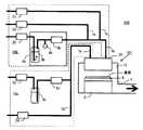
図1は本発明の成膜装置100の第1例の概略図である。<Configuration of film forming apparatus>
FIG. 1 is a schematic view of a first example of a
成膜装置100は、成膜ユニット101と、この成膜ユニット101に第1のガスを供給するための第1ガス供給部10a、および成膜ユニット101に第2のガスを供給するための第2ガス供給部10bを具備している。成膜ユニット101は、内部に成膜室11を有する本体部1と、ガス導入ユニット20、および図示しない成膜室11の圧力調整装置、排気装置、排気ガスの除害装置などからなり、成膜室11内にはヒーター8およびサセプター9が配置されている。成膜対象物としての基板はサセプター9上に置かれる。図示しないが、さらに成膜ユニット101は成膜室11に接続されるロードロック室や基板搬送系を設けても良い。 The
第1ガス供給部10aは図示しない不活性ガスボンベ、減圧弁などからなる不活性ガス供給部から送られた不活性ガスの流量を調整する流量調整器2a、原料容器3a、圧力計4a、圧力調整器5a、配管7aなどからなり、原料容器3a、圧力計4a、および圧力調整器5aは恒温槽6a内に納められている。また、配管7aは図示しない配管ヒーターおよび温度制御装置によって所望の温度に加熱される。 The first
同様に第2ガス供給部10bは図示しない不活性ガスボンベ、減圧弁などからなる不活性ガス供給部から送られた不活性ガスの流量を調整する流量調整器2b、原料容器3b、圧力計4b、圧力調整器5b、配管7bなどからなり、原料容器3b、圧力計4b、および圧力調整器5bは恒温槽6b内に納められている。また、配管7bは図示しない配管ヒーターおよび温度制御器によって所望の温度に加熱される。第2ガス供給部は更に膜の導電性を制御するための微量添加ガスを導入するために、図示しないガスボンベ、減圧弁などからなる微量添加ガス供給部から送られた微量添加ガスの流量を調整する流量調整器2cおよび配管7cを設けても良い。 Similarly, the second
成膜の動作について説明する。不活性ガス供給部から送られた不活性ガスは流量調整装置2a,2bにより流量を調整され、原料容器3a,3bに送られる。ここで原料容器内の原料はバブリングされ、恒温槽6a,6bにより設定された所望の温度で得られる蒸気圧分の各原料ガスが原料容器に導入された不活性ガスによって搬送される。原料容器の圧力は圧力計4a,4bによって測定された値が所望の一定値になるよう、圧力調整器5a,5bによって調整される。搬送される原料ガスの蒸気圧は原理的には恒温槽の温度にのみ依存するため、原料容器の圧力を調整することにより配管7a,7bを流れる原料ガスの濃度を調整することができる。 The film forming operation will be described. The flow rate of the inert gas sent from the inert gas supply unit is adjusted by the flow
さらに原料ガス濃度の調整幅を拡大するために、図2の成膜装置200の第2例に示したように、原料容器を通さずに不活性ガスを供給するための流量調整装置2d,2e、配管7d,7eを設け、原料容器より下流で合流させても良い。 Further, in order to expand the adjustment range of the source gas concentration, as shown in the second example of the
また、図3の成膜装置300の第3例に示したように、原料容器から液体状の原料を圧力によって配管に押し出し、気化器5cによって直接気化する方法を用いることもできる。ただし、気化器5cには通常高温がかけられるため、原料が必要な蒸気圧を得るために必要な温度よりも低温で分解する場合には使用できない。バブリングでは必ず原料を気化させるためのキャリアガスが必要であるが、気化器5cを用いることによってキャリアガスを含まない純粋な原料を気化させることができるようになるため、原料濃度をより自由に設定することができるようになる。 Further, as shown in the third example of the
図1〜図3の第1ガス供給部10aおよび第2ガス供給部10bで使用する不活性ガスにはアルゴン、窒素、ヘリウムなどを用いることができる。また、微量添加ガスは水素、アルゴン、窒素、ヘリウムなどで希釈されたものを用いても良い。流量調整器2a,2b
,2c,2d,2eにはマスフローコントローラーを用いることができる。圧力調整器5a,5bにはメータリングバルブやピエゾバルブを用いることができる。配管7a,7bは加熱されていることにより、原料容器内で原料が気化するために起こる原料容器の温度低下を防ぎ、また、原料ガスが配管内で結露するのを防ぐ。Argon, nitrogen, helium, or the like can be used as an inert gas used in the first
, 2c, 2d, 2e can use mass flow controllers. Metering valves and piezo valves can be used for the
各ガスは配管7a,7bを通って、ガス導入ユニット20に供給される。ガス導入ユニット20についての詳細は後述するが、この中では各ガスは混合されず、分離された状態で成膜室11に導入される。導入されたガスは成膜室11内で反応し、ヒーター8で加熱された基板上に膜が成膜される。さらに均熱のためにサセプター9を設けても良い。成膜室11は図示しない圧力調整装置によって、所望の成膜圧力に制御されている。圧力調整装置は成膜室11内の圧力を測定し、この値が所望の値になるようオリフィスの開度を調整して排気量を制御することにより、成膜室内を一定の圧力に制御する機能を有する。そして反応済みのガスは図示しないポンプによって排気される。除害のためにトラップやスクラバーを設けても良い。 Each gas is supplied to the
なお、図1〜図3に示すように、上記第1例〜第3例の各成膜装置100,200,300として、成膜ユニット101を具備した例が記載されているが、成膜ユニット101に限定されず、後述する各種成膜ユニット101〜103のいずれを具備していてもよい。 In addition, as shown in FIGS. 1-3, although the example provided with the film-forming
<第1実施形態に係る成膜ユニットの構成>
図4は第1実施形態に係る成膜ユニット101におけるガス導入ユニット20の周辺の概略断面図である。また図5は図4のA−A断面からガス導入ユニット20を見た図である。第1のガスをガス導入ユニット20に供給するための配管7a(以後、第1の配管7aという)および第2のガスをガス導入ユニット20に供給するための配管7b(以後、第2の配管7bという)は天板21の第1の導入部21aおよび第2の導入部21bにそれぞれ溶接されている。ガス導入ユニット20内における第1のガスの流路としてのパイプは、第1の導入部21aから成膜室11へ延びている。なお、本実施形態においては、第1のガスの流路としてのパイプは、第1の配管7aの延長部として構成されている。第1の配管7a(パイプ7a)はガス導入ユニット20内部で曲げられたり分岐したりすることなく、天板21からシャワープレート23bに設けられた穴(以後、第1のガス吐出口という)に向けて、シャワープレート23に対して略垂直に延伸している。そして、第1のガスは第1の配管7a(パイプ7a)の先端から成膜室11内へと供給される。<Configuration of Film Formation Unit According to First Embodiment>
FIG. 4 is a schematic sectional view of the periphery of the
一方、第2のガスは、第2の配管7bからガス導入ユニット20の第2の導入部21bに導入された後、枠状の部材22a,22b及びシャワープレート23a,23bによって囲まれた空間(以後、拡散室とする。)24a,24bに拡散する。枠状の部材22a,22bはガス導入ユニット20の外壁に相当し、第2のガスを一定の領域に閉じこめると共に、その厚みを変更することにより拡散室24a,24bの厚みを調整する機能を有する。本枠状の部材22a,22bはシャワープレート23a,23bと共にボルトで天板21に固定される。シャワープレート23a,23bは複数の穴(以後、第2ガス吐出口という)を有する板状の部材である。第2のガスは23bの第2ガス吐出口から基板に向けて、成膜室11内へと供給される。シャワープレート23a,23bの第2ガス吐出口の分布や数を調整したり、枠状の部材22a,22bの厚みを調整したりすることにより、第2のガスを基板面内に対して概ね均一に供給することができる。 On the other hand, after the second gas is introduced from the
シャワープレート23a,23bは枠状の部材22a,22bおよび配管7aの周囲を取り囲む柱状部材25a,25b,25cによって固定される。柱状部材25aは筒状であり、螺合面26aで天板21と螺合するよう加工されている。また柱状部材25aと25bはシャワープレート23aの上下を挟み込んで固定し、螺合面26bで螺合するよう
加工されている。また柱状部材25bと25cはシャワープレート23bを上下に挟みこんで固定し、螺合面26cで螺合するよう加工されている。柱状部材25a,25b,25cは第1配管7aとシャワープレート23a,23bとを微細な位置合わせの必要無く固定する機能を有する。The
以上のような構成によって、第1実施形態に係る成膜ユニット101は、メンテナンスが容易であるとともに、設定できる成膜条件の範囲が広く、大面積の基板に対しても面内でばらつきの少ない成膜を行なうことができる。 With the above configuration, the
つまり、第1のガスを供給する流路が、第1の導入部21aから成膜室11へ延びるパイプ7aという単純な形であるため、第2のガスを供給する流路を微細な位置合わせ無しに、単純な構成の拡散室24a,24bとシャワープレート23a,23bで作製することができる。また、拡散室24a,24bとシャワープレート23a,23bにより、第2のガスを基板の面内に均一に供給することができる。また、シャワープレート23a,23bは第1のガスを供給する流路との複雑な噛み合いが無いため、簡単に取り外すことができ、容易に洗浄などのメンテナンスを行うことができる。また、パイプ7aは天板21とシャワープレート23a,23bとを接続する柱状部材25a,25b,25cに囲まれている。そのため、第1のガスと第2のガスの分離をより完全にすることができ、また、パイプ7a自体がシャワープレートに溶接などの手段により一体化されていないため、分解することも容易である。そのため、容易に洗浄などのメンテナンスを行うことができる。 That is, since the flow path for supplying the first gas has a simple shape of the
また、柱状部材25a,25b,25cは、天板21とシャワープレート23a,23bとを連続的に接続しているため、柱状部材25a,25b,25cとして、金属などの良熱伝導材料を用いることにより、柱状部材25a,25b,25cを介してシャワープレート23a,23bを放熱することができる。つまり、柱状部材25a,25b,25cは、シャワープレート23a,23bに印加されるヒーターからの輻射熱を天板21へと放熱する機能を有する。例えば天板21上面に冷却水配管13を取り付け、これに冷却水を流すことにより天板21を冷却すると、より効果的にシャワープレート23bを冷却することができる。シャワープレート23bを冷却することにより、ヒーターからの輻射により温められたシャワープレート23bに膜が付着するのをある程度防止することができ、メンテナンスの頻度を下げることができる。また、ガス導入ユニット20内部のガスが熱により分解するのを防ぐことができる。このような構造とすることにより、非常に簡単な構成で、第1のガスと第2のガスをガス導入ユニット20の内部で混じり合うことなく、成膜室11へと導入することが可能になる。 Further, since the
第1のガスはガス導入ユニット20から局所的に供給されることになるが、適切な流量、濃度、成膜圧力を選択することにより、比較的広い成膜条件範囲で、ガス導入ユニット20から基板に至るまでの空間で充分拡散させることができる。一方で第2のガスはガス導入ユニット20から概ね均一に供給され、基板に至るまでの空間でさらに拡散するため、第1の配管7a直下にも第2のガスは供給され成膜することができる。特に、第1のガスを水などの酸化ガスを含むガスとし、第2のガスをジエチル亜鉛などの金属原料ガスを含むガスとし、第1のガスに含まれる酸化ガスのモル濃度が第2のガスに含まれる金属原料ガスのモル濃度よりも充分高い成膜条件としておくことにより、基板全面にシャワープレートを介して概ね均一に供給された金属原料ガスが、金属原料ガスよりも過剰に供給された酸化ガスによって充分に酸化されるため、より品質が良く(酸素欠陥が少なく透過率が高い)、基板面内で均一な酸化膜を得ることができる。 The first gas is locally supplied from the
基板全面における膜質の均一化をさらに良好に行なうという観点からは、シャワープレート23a,23bは、例えば、図5に示すように、第1のガス吐出口の周囲を取り囲む
ように複数の第2のガス吐出口が配置されていてもよい。From the standpoint of further uniforming the film quality over the entire surface of the substrate, the
例えば、シャワープレート23a,23bは例えば直径0.5〜1mmの穴(第2のガス吐出口)を10mmピッチで設けた厚さ1〜2mm、直径30cm程度以下の円板である。枠状の部材22a,22bの厚みは0.2〜3cm程度である。柱状部材25a,25b,25cは直径1〜2cm程度である。 For example, the
本例では拡散室をシャワープレート23aで仕切って24a,24bの上下2段に設けたが、1段だけの構成でもかまわない。本例のように2段にすることにより、より均一に第2のガスを拡散させることができる。 In this example, the diffusion chamber is partitioned by the
また、枠状の部材22a,22bとシャワープレート23a,23bとの間、および柱状部材25a,25b,25cとシャワープレート23a,23bとの間、天板21と枠状の部材22aとの間、天板21と柱状部材25aとの間にはシリコン樹脂やフッ素樹脂でできたパッキンを挟むと、より確実に気密をとることができる。パッキンを挟むことにより、各部材の平面精度に対して余裕ができ、より加工公差を緩めることができる。また、熱膨張によってシャワープレート23a,23bが多少変形しても、パッキンがあることにより、気密を確保し続けることができる。 Also, between the frame-shaped
特に、柱状部材25a,25b,25cの内側と外側とが気密に分離されている場合、成膜ユニット101のメンテナンスをより容易にすることができる。つまり、柱状部材25a,25b,25cの気密性が低いと、柱状部材25a,25b,25cの内側に第2のガスが浸入し、第1の配管7a(パイプ7a)を伝ってパイプ7aの端部で第1のガスと反応しやすくなるため、パイプ7aの端部に膜が付着してメンテナンスが困難になりやすくなる。一方、柱状部材25a,25b,25cの内側と外側とが気密に分離されている場合、このようなパイプ7aの端部での膜の付着を良好に低減できる。 In particular, when the inner side and the outer side of the
また、柱状部材25a,25b,25cはここではそれぞれが螺合する例を示したが、ボルトで固定しても良い。螺合させる方が固定に必要な面積が少なくて良いため、シャワープレート23a,23bの第2のガス吐出口を、第1の配管7aが設けられている第1のガス吐出口の近くまで接近させることができる。その結果、第1の配管7aの直下において成膜される膜の膜厚と他の部位の膜厚との差をより小さくすることができる。 In addition, the
本ガス導入ユニット20は容易に組み立て・分解することができ、着膜が起こっても各部品を取り外して洗浄することができる。 The
また、例えば基板の温度分布や排気位置などのガス導入ユニット20からのガスの供給分布によらずに発生する膜厚分布を補正したい場合、第2のガスの供給量を基板面内で補正することが有効であるが、本発明のガス導入ユニット20によればシャワープレート23bの第2のガス吐出口の穴径・穴位置・穴数などを変更するだけで第2のガスの供給量分布を補正することができる。 For example, when it is desired to correct the film thickness distribution generated regardless of the gas supply distribution from the
第1のガスを供給する第1の配管7aの位置(第1のガス吐出口の位置)は排気位置を考慮して決定するべきである。図1のように排気口が成膜室11の紙面右側にある場合、図5のように第1の配管7aは、基板中心よりもやや紙面左(上流)側にある方が、基板に均一に第1のガスを供給するには有利である。もし、排気を基板の外周から均一に行えるのであれば、第1の配管7aは基板中央の直上に位置するべきである。 The position of the
ガス導入ユニット20は、本体部1の成膜室外壁14に固定されるが、間にスペーサー15を挟んでも良い。スペーサー15は枠状の部材である。スペーサー15の厚みを調整
することによって、シャワープレート23bと基板との距離を調整することができる。ガス導入ユニット20、スペーサー15および成膜室外壁14の間には、外部空間と成膜室11とを気密に分離するためのパッキンを設けても良い。The
<他の実施形態に係る成膜ユニットの構成>
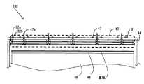
図6〜図8はより大型の基板に成膜する場合の構成(第2実施形態に係る成膜ユニット102)を示した装置の概略図である。図6は成膜ユニット102のガス導入ユニット40を下側(成膜室41側)から見た図、図7は図6のB−B断面図、図8は図6のC−C断面図である。成膜ユニット102の成膜室41とガス導入ユニット40以外の部分の構成は図1と同様であるため、説明を省略する。図7に示したとおり、大型化した装置の一部分は小型な装置の構造と同様であり、これを連続的に並べることにより大型化することができるものである。その際、シャワープレート33bは微細な位置合わせが不要なため、一体に作製することができる。なお、図6にはガス導入ユニット40の大気側(成膜室41とは反対側)に設けられている部材として、冷却水配管43と第2のガスを供給する第2の配管47bも点線で示している。<Configuration of Deposition Unit According to Other Embodiment>
6 to 8 are schematic views of an apparatus showing a configuration (
第1のガスを供給する第1の配管47aは図4、図5の例と同じく天板31に対して略垂直に接続されている。冷却水配管43は天板31全面に亘って配置される。その際、第1の配管47a近傍を通るようにしておくことにより、より効率良くシャワープレート33bを冷却することができる。第2配管47bはガス導入ユニット40よりも上流で分岐されており、この例では2箇所で天板31に接続されている。第1の配管47aも同様にガス導入ユニット40より上流で分岐されており、この例では14箇所で天板31に接続されている。分岐と天板31への接続の様子を示した斜視図が図9である。大面積を成膜するためには、大流量のガスが必要であるため、第1の配管47a,第2の配管47bは圧力損失を避けるために比較的太い配管を用いている。配管や分岐配管用部材は工業製品の規格があるため、ガス導入ユニット40の内部で分岐する流路を作るより、装置全体を比較的安価に作製することができる。また、ガス導入ユニット40の外部では基板を加熱するヒーターからの輻射の影響が無く寸法も大きいため、熱による変形や加工の寸法誤差のための寸法公差に余裕ができる。分岐数や配管径は所望の特性が得られるよう、設計すれば良い。 The
また、図10の第3実施形態に係る成膜ユニット103のように、第1の配管47aにはガス導入ユニット40よりも上流に、各供給配管から供給されるガスの流量を制御するための調整バルブ48を設けても良い。調整バルブ48を設けることにより、より細かく第1のガス供給量を基板面内で調整することができる。従って、より基板の面内分布を調整することが容易になる。特に、ガス導入ユニット40を組み上げて実際の成膜結果を見てから、バルブ48の開度を調整することでガスの供給量を制御して面内分布を調整することができるため便利である。もちろん、第2のガスを供給する第2の配管47bに調整バルブを設けても良い。 Further, as in the
上記第2実施形態に係る成膜ユニット102および第3実施形態に係る成膜ユニット103は、1個の第1ガス供給部から供給される第1のガスを分岐してガス導入ユニット40の複数の第1の導入部31aへ供給している例であるが、第1ガス供給部をガス導入ユニット40内の第1の導入部31aの数だけ設けてもよい。これによって、各第1の導入部31a毎に流量調整器や恒温槽温度の設定を変えることができるようになるので、より精密に第1のガス供給量を基板面内で調整することができる。 The
上記第2実施形態に係る成膜ユニット102および第3実施形態に係る成膜ユニット103において、ガス導入ユニット40への第1の配管47aおよび第2の配管47bの接続は溶接しても良いし、ガスケットを介して気密に接続しても良い。 In the
例えば、シャワープレート33a,33bは例えば直径0.5〜1mmの第2のガス吐出口を10〜20mmピッチで設けた厚さ1〜2mm、100cm×160cm程度の板である。枠状の部材32a,32bの厚みは1〜4cm程度である。柱状部材35a,35b,35cは直径1〜5cm程度である。第1の配管47bは約30cmピッチである。 For example, the
さて、金属酸化膜を成膜する際には、酸化ガスで金属原料ガスを酸化させるが、上記第1実施形態〜第3実施形態に係る成膜ユニット101,102,103を用いるに際し、第1のガスが酸化ガスを含み、第2のガスが金属原料ガスを含むようにするのが好適である。本発明の成膜ユニットの構造を採ると、第1のガスの成膜室内での分布はある程度偏る。金属酸化膜は金属原料ガスに含まれる金属が酸化した膜なので、金属原料ガスの分布が偏っていると得られる膜の基板面内分布は偏り易い。従って、金属原料ガスはシャワープレートを用いて基板上になるべく均一な分布で噴射するべきである。一方、酸化ガスは充分に供給することにより、分布に偏りがあっても、金属原料ガスを酸化するために使った残りの未反応ガスはただ排気されるだけであるので、分布には大きな影響を与えない。例えば酸化ガスを水とし、金属原料ガスをジエチル亜鉛とした場合には、水のモル量をジエチル亜鉛のモル量よりも多くしておく。ジエチル亜鉛はシャワープレートにより成膜室の広い領域で均一に噴射される。これを充分な量の水で酸化することにより、基板上には面内分布の小さい膜を得ることができる。水のモル量がジエチル亜鉛のモル量よりも少ない場合には、酸化が不完全となり、得られる膜は酸素欠陥の入った黒っぽい膜になってしまう。 Now, when forming the metal oxide film, the metal source gas is oxidized with the oxidizing gas. However, when the
なお、本発明は上述の実施の形態に限定されるものではなく、本発明の要旨を逸脱しない範囲において種々の変更、改良などが可能である。 The present invention is not limited to the above-described embodiment, and various changes and improvements can be made without departing from the scope of the present invention.
本例では図4の成膜ユニット101の構造を採用した図2の成膜装置200を用い、BZO薄膜を成膜した。 In this example, a BZO thin film was formed by using the
第1のガスを供給する第1の配管7aおよび第2のガスを供給する第2の配管7bは外径6.35mmの直管であり、天板21に溶接されている。ガス導入ユニット20を組み立てる際には、天板21を成膜室外壁14から持ち上げて上下反転させて作業した。第1の配管7a,第2の配管7bは天板21近傍で上流の配管から取り外せるように、上流の配管とガスケットを介して気密に接続できる接続部を設けておくと良い。循環冷却水配管についても同様である。 The
組み立てはまず、天板21に溶接されている第1の配管7aを囲む柱状部材25aを天板21にねじ込み、枠状の部材22aを天板21上に設置した。本例では気密をより完全にするために柱状部材25aおよび枠状の部材22aにはOリング用の溝を設け、Oリングを設置した。枠状の部材22aは外径28cm、幅20mm、厚みは4mmの円筒である。柱状部材25aは天板21と柱状部材25bと螺合するネジ部を有する外径25mmの円柱であり、第1の配管7aを差し入れる内径は6.40mmと取り外しが容易なように第1の配管7aの外径6.35mmより大きくしている。 First, the
次にシャワープレート23aを枠状の部材22aおよび柱状部材25aの上に置き、柱状部材25bを柱状部材25aにねじ込んで、柱状部材25aと柱状部材25bとの間にシャワープレート23aを固定した。シャワープレート23aは厚み1mm、外径28cmの円板であり、第2のガスを拡散室24aから拡散室24bへと導く穴を設けている。この例ではシャワープレート23aの中心から半径5cmの円周上に直径1mmの穴を等
間隔で8個配置した。また、第1の配管7aを差し入れる内径7.05mmの穴を設けている。Next, the
次に、枠状の部材22bとOリングをシャワープレート23a上に置き、この枠状の部材22bおよび柱状部材25bの上にシャワープレート23bを置き、次に柱状部材25cを柱状部材25bにねじ込んで、柱状部材25bと柱状部材25cとの間にシャワープレート23bを固定した。そして、枠状の部材22a,22b、シャワープレート23a,23bを貫通して天板21に固定するボルトでこれらを固定した。枠状の部材22bの厚みは6mmである。シャワープレート23bは中心の12cm×12cmのエリアに、第2のガスを拡散室24bから成膜室11へと導く直径0.5mmの穴を、ピッチ10mmの等間隔に設けている。第1の配管7aの中心はシャワープレート23bの中心から3cm外側に位置するように配置されている。組み上がったガス導入ユニット20は成膜室外壁14にOリングとスペーサー15を介して設置した。シャワープレート23bの表面とサセプター表面との距離は、スペーサー15の厚みを選択することにより6cmとした。最後に、第1の配管7a,第2の配管7bおよび冷却水配管を上流の配管と接続した。 Next, the frame-shaped
成膜対象物としての基板には、12cm×12cm、厚み2mmガラスを用い、図示していない搬送系を用い、外径24cmのヒーター8上に設置した外径25cmのSiC製サセプター9の中央に搬送した。前述したように、基板に対向するシャワープレート23bの領域にはピッチ10mmで第2のガスを噴射する穴(第2ガス吐出口)がある。排気は紙面右側から行い、第1のガスを噴射する穴(第1ガス吐出口)は、中央から排気とは逆側に3cmのところにある。 A 12 cm × 12 cm, 2 mm thick glass is used as a substrate as a film formation target, and a transport system (not shown) is used, and a
原料には水とジエチル亜鉛を用い、導電性を持たせるために水素希釈ジボランガスを添加した。原料容器は恒温槽内に設置し、アルゴンガスでバブリングすることにより気化させた。なお、水は第1のガスに含ませ、ジエチル亜鉛および水素希釈ジボランガスは第2のガスに含ませた。成膜条件を表1に示す。条件1は次に説明する比較例と比較するために、比較例のシャワー配管構造に対して最適化した条件である。一方、条件2は本発明の実施例の構造に対して面内分布の改善を検討した条件である。第1のガスの流量が大きすぎると、第1の配管7a直下と周辺部との膜厚差が大きくなってしまう。そこで、第1の配管7aを流れる第1のガスの量をなるべく減らし、且つ、外周部まで充分な量の水が行き届くように、水の濃度と第1の配管7aを流れる総ガス量を調整した。また、第2のガス側も希釈ガスを減らし、ジエチル亜鉛の濃度を上げた。 Water and diethyl zinc were used as raw materials, and hydrogen diluted diborane gas was added to provide conductivity. The raw material container was installed in a thermostat and was vaporized by bubbling with argon gas. Water was included in the first gas, and diethylzinc and hydrogen diluted diborane gas were included in the second gas. The film forming conditions are shown in Table 1.

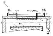
比較例としては、従来のシャワー配管を用いてBZOを成膜した。シャワー配管を用いたガス導入ユニット104の概略断面図を図11に示す。また、図11のD−D断面からガス導入ユニット104側を見た様子を図12に示す。シャワー配管は外径6.35mmの配管を櫛歯状に接続したものを対向させたものである。配管の基板に対向する側には直径0.5mmの穴を10mmピッチで13個設けている。シャワー配管7a’からは第1のガスが、シャワー配管7b’からは第2のガスが供給される。シャワー配管7a’および7b’は天板21’に溶接して固定した。天板21’の大気側(成膜室11とは反対側)には冷却水配管13’を溶接し、シャワー配管を冷却した。効果的に冷却するにはシャワー配管全体を天板21’に接触させる必要があるため、一組のジエチル亜鉛・水配管対と隣り合う次の配管対との間には溶接作業を行うための空間を配管1本分の幅で設けている。成膜条件は表1と同様で、シャワー配管の表面からサセプターまでの距離は6cmである。 As a comparative example, a BZO film was formed using a conventional shower pipe. A schematic sectional view of the
本発明の実施例である条件1と条件2、および比較例の結果を比較した。表2はそれぞれの膜厚分布を比較したものである。膜厚は基板面内17点を測定した。膜厚の最大値をMax.とし、最小値をMin.としたときに、分布は(Max.−Min.)/(Max.+Min.)×100で計算した。シャワー配管を用いた比較例と同じ成膜条件である条件1では非常に大きな分布となってしまっているが、本発明の構造に対して成膜条件を検討した条件2とすることにより、従来のシャワー配管を用いた比較例の場合と同等以上の良好な面内分布とすることができた。 The
シャワープレート23bは柱状部材25a,25b,25cを介して冷却されてはいるが完全ではないため、徐々に着膜が進んだ。その際にはシャワーヘッド20を組み立てたときとは逆の手順で分解し、シャワープレート23b、枠状の部材22a,22b、および柱上部材25cを酸により洗浄した。拡散室24a,24bは各ガスが気密に分離されていたため、拡散室の内側に汚れはなかったが、より長期間の使用により汚れが生じた場合には同様に分解して洗浄することができる。酸で洗浄した各部材は純水でよく洗浄し、オーブンで乾燥させた後、再び組み立てて、使用した。このように本発明の上記実施例では、メンテナンスが容易であることが確認できた。 Although the
1:本体部
2a〜2e:流量調整器
3a,3b:原料容器
4a,4b:圧力計
5a〜5c:圧力調整器
6a,6b:恒温槽
7a,47a:第1の配管
7b,47b:第2の配管
8,48:ヒーター
9,49:サセプター
10:ガス供給部
11,41:成膜室
13,43:冷却水配管
14,44:成膜室外壁
15:スペーサー
20,40:ガス導入ユニット
21,31:天板
21a,31a:第1の導入部
21b,31b:第2の導入部
22a,22b,32a,32b:枠状の部材
23a,23b,33a,33b:シャワープレート
24a,24b,34a,34b:拡散室
25a〜25c,35a〜35c:柱状部材
26a〜26c:螺合面
100,200,300:成膜装置
101〜103:成膜ユニット1:
Claims (10)
Translated fromJapanese前記ガス導入ユニットは、
前記第1のガスを導入するための第1の導入部および前記第2のガスを導入するための第2の導入部を有するとともに前記本体部の外部と内部とを隔てる天板と、
前記第1の導入部から前記成膜室へ延びるパイプと、
前記天板との間に拡散室を介して配置されており、前記第2のガスを前記拡散室から前記成膜室へ供給するための複数の第2のガス吐出口を有するとともに、前記パイプと繋がるように開口して前記第1のガスを前記パイプから前記成膜室へ供給するための第1のガス吐出口を有するシャワープレートと、
内側に前記パイプが挿入されているとともに前記天板と前記シャワープレートとを接続する筒状の柱状部材とを有することを特徴とする成膜ユニット。A film forming unit having a main body having a film forming chamber therein, and a gas introduction unit for introducing the first gas and the second gas into the film forming chamber,
The gas introduction unit includes:
A top plate having a first introduction part for introducing the first gas and a second introduction part for introducing the second gas and separating the outside and the inside of the main body part;
A pipe extending from the first introduction part to the film formation chamber;
A plurality of second gas outlets for supplying the second gas from the diffusion chamber to the film formation chamber, and disposed between the top plate and the top plate; A shower plate having a first gas outlet for opening the first gas and supplying the first gas from the pipe to the film formation chamber;
A film forming unit comprising: a tubular columnar member that has the pipe inserted therein and connects the top plate and the shower plate.
Priority Applications (1)
| Application Number | Priority Date | Filing Date | Title |
|---|---|---|---|
| JP2013084832AJP2014205892A (en) | 2013-04-15 | 2013-04-15 | Film deposition unit and film deposition apparatus |
Applications Claiming Priority (1)
| Application Number | Priority Date | Filing Date | Title |
|---|---|---|---|
| JP2013084832AJP2014205892A (en) | 2013-04-15 | 2013-04-15 | Film deposition unit and film deposition apparatus |
Publications (1)
| Publication Number | Publication Date |
|---|---|
| JP2014205892Atrue JP2014205892A (en) | 2014-10-30 |
Family
ID=52119693
Family Applications (1)
| Application Number | Title | Priority Date | Filing Date |
|---|---|---|---|
| JP2013084832APendingJP2014205892A (en) | 2013-04-15 | 2013-04-15 | Film deposition unit and film deposition apparatus |
Country Status (1)
| Country | Link |
|---|---|
| JP (1) | JP2014205892A (en) |
Cited By (3)
| Publication number | Priority date | Publication date | Assignee | Title |
|---|---|---|---|---|
| JP2018101721A (en)* | 2016-12-21 | 2018-06-28 | 株式会社ニューフレアテクノロジー | Vapor growth method |
| JP2019153630A (en)* | 2018-03-01 | 2019-09-12 | 株式会社ニューフレアテクノロジー | Vapor growth method |
| WO2025072630A1 (en)* | 2023-09-30 | 2025-04-03 | L'air Liquide, Societe Anonyme Pour L'etude Et L'exploitation Des Procedes Georges Claude | Zinc, zinc-containing film deposition and zinc-containing alloy formation using zinc and hydrogen sources |
- 2013
- 2013-04-15JPJP2013084832Apatent/JP2014205892A/enactivePending
Cited By (4)
| Publication number | Priority date | Publication date | Assignee | Title |
|---|---|---|---|---|
| JP2018101721A (en)* | 2016-12-21 | 2018-06-28 | 株式会社ニューフレアテクノロジー | Vapor growth method |
| JP2019153630A (en)* | 2018-03-01 | 2019-09-12 | 株式会社ニューフレアテクノロジー | Vapor growth method |
| JP7180984B2 (en) | 2018-03-01 | 2022-11-30 | 株式会社ニューフレアテクノロジー | Vapor growth method |
| WO2025072630A1 (en)* | 2023-09-30 | 2025-04-03 | L'air Liquide, Societe Anonyme Pour L'etude Et L'exploitation Des Procedes Georges Claude | Zinc, zinc-containing film deposition and zinc-containing alloy formation using zinc and hydrogen sources |
Similar Documents
| Publication | Publication Date | Title |
|---|---|---|
| US10529542B2 (en) | Cross-flow reactor and method | |
| TWI525734B (en) | And a raw material gas supply device for a semiconductor manufacturing apparatus | |
| JP6526160B2 (en) | Vapor delivery device, method of making the same and method of using the same | |
| US12180589B2 (en) | Showerhead for process tool | |
| US8960235B2 (en) | Gas dispersion apparatus | |
| KR102360546B1 (en) | Flow balancing in gas distribution networks | |
| CN100585828C (en) | Substrate mounting table, substrate processing device, and temperature control method | |
| US20060127068A1 (en) | Method and apparatus for silicon oxide deposition on large area substrates | |
| US20110087378A1 (en) | Control method and processor of exhaust gas flow rate of processing chamber | |
| CN101760727A (en) | Material gas concentration control system | |
| CN104822858A (en) | Feedstock gasification and supply device | |
| KR101768746B1 (en) | Gas supplying head, gas supplying mechanism and substrate processing apparatus | |
| US6488775B2 (en) | Semiconductor-manufacturing device | |
| US20170362701A1 (en) | Central source delivery for chemical vapor deposition systems | |
| JP2014205892A (en) | Film deposition unit and film deposition apparatus | |
| TW200847243A (en) | Apparatus and method for forming film | |
| US11476132B2 (en) | Sealing structure, vacuum processing apparatus and sealing method | |
| JP4899958B2 (en) | Film forming method and film forming apparatus | |
| JP2007201098A (en) | Vapor growth apparatus and vapor growth method | |
| US20150010718A1 (en) | Heat transfer control in pecvd systems | |
| TWI822023B (en) | Gas shower heads and chemical vapor deposition equipment | |
| US20250163581A1 (en) | Dual plenum showerhead with center to edge tunability | |
| US20200258762A1 (en) | Temperature control apparatus | |
| WO2020195820A1 (en) | Substrate-processing device and production method for substrate-processing device | |
| KR20070089817A (en) | Substrate Surface Treatment Device |