JP2014204984A - Sensor module and robot cleaner including the same - Google Patents
Sensor module and robot cleaner including the sameDownload PDFInfo
- Publication number
- JP2014204984A JP2014204984AJP2014079986AJP2014079986AJP2014204984AJP 2014204984 AJP2014204984 AJP 2014204984AJP 2014079986 AJP2014079986 AJP 2014079986AJP 2014079986 AJP2014079986 AJP 2014079986AJP 2014204984 AJP2014204984 AJP 2014204984A
- Authority
- JP
- Japan
- Prior art keywords
- light
- robot cleaner
- sensor
- reflecting mirror
- obstacle
- Prior art date
- Legal status (The legal status is an assumption and is not a legal conclusion. Google has not performed a legal analysis and makes no representation as to the accuracy of the status listed.)
- Pending
Links
Images


Classifications
- A—HUMAN NECESSITIES
- A47—FURNITURE; DOMESTIC ARTICLES OR APPLIANCES; COFFEE MILLS; SPICE MILLS; SUCTION CLEANERS IN GENERAL
- A47L—DOMESTIC WASHING OR CLEANING; SUCTION CLEANERS IN GENERAL
- A47L9/00—Details or accessories of suction cleaners, e.g. mechanical means for controlling the suction or for effecting pulsating action; Storing devices specially adapted to suction cleaners or parts thereof; Carrying-vehicles specially adapted for suction cleaners
- A47L9/28—Installation of the electric equipment, e.g. adaptation or attachment to the suction cleaner; Controlling suction cleaners by electric means
- A—HUMAN NECESSITIES
- A47—FURNITURE; DOMESTIC ARTICLES OR APPLIANCES; COFFEE MILLS; SPICE MILLS; SUCTION CLEANERS IN GENERAL
- A47L—DOMESTIC WASHING OR CLEANING; SUCTION CLEANERS IN GENERAL
- A47L9/00—Details or accessories of suction cleaners, e.g. mechanical means for controlling the suction or for effecting pulsating action; Storing devices specially adapted to suction cleaners or parts thereof; Carrying-vehicles specially adapted for suction cleaners
- A47L9/009—Carrying-vehicles; Arrangements of trollies or wheels; Means for avoiding mechanical obstacles
- A—HUMAN NECESSITIES
- A47—FURNITURE; DOMESTIC ARTICLES OR APPLIANCES; COFFEE MILLS; SPICE MILLS; SUCTION CLEANERS IN GENERAL
- A47L—DOMESTIC WASHING OR CLEANING; SUCTION CLEANERS IN GENERAL
- A47L9/00—Details or accessories of suction cleaners, e.g. mechanical means for controlling the suction or for effecting pulsating action; Storing devices specially adapted to suction cleaners or parts thereof; Carrying-vehicles specially adapted for suction cleaners
- A47L9/28—Installation of the electric equipment, e.g. adaptation or attachment to the suction cleaner; Controlling suction cleaners by electric means
- A47L9/2805—Parameters or conditions being sensed
- B—PERFORMING OPERATIONS; TRANSPORTING
- B25—HAND TOOLS; PORTABLE POWER-DRIVEN TOOLS; MANIPULATORS
- B25J—MANIPULATORS; CHAMBERS PROVIDED WITH MANIPULATION DEVICES
- B25J13/00—Controls for manipulators
- B25J13/08—Controls for manipulators by means of sensing devices, e.g. viewing or touching devices
- B—PERFORMING OPERATIONS; TRANSPORTING
- B25—HAND TOOLS; PORTABLE POWER-DRIVEN TOOLS; MANIPULATORS
- B25J—MANIPULATORS; CHAMBERS PROVIDED WITH MANIPULATION DEVICES
- B25J9/00—Programme-controlled manipulators
- B25J9/16—Programme controls
- G—PHYSICS
- G01—MEASURING; TESTING
- G01S—RADIO DIRECTION-FINDING; RADIO NAVIGATION; DETERMINING DISTANCE OR VELOCITY BY USE OF RADIO WAVES; LOCATING OR PRESENCE-DETECTING BY USE OF THE REFLECTION OR RERADIATION OF RADIO WAVES; ANALOGOUS ARRANGEMENTS USING OTHER WAVES
- G01S17/00—Systems using the reflection or reradiation of electromagnetic waves other than radio waves, e.g. lidar systems
- G01S17/02—Systems using the reflection of electromagnetic waves other than radio waves
- G01S17/06—Systems determining position data of a target
- G01S17/46—Indirect determination of position data
- G01S17/48—Active triangulation systems, i.e. using the transmission and reflection of electromagnetic waves other than radio waves
- G—PHYSICS
- G01—MEASURING; TESTING
- G01S—RADIO DIRECTION-FINDING; RADIO NAVIGATION; DETERMINING DISTANCE OR VELOCITY BY USE OF RADIO WAVES; LOCATING OR PRESENCE-DETECTING BY USE OF THE REFLECTION OR RERADIATION OF RADIO WAVES; ANALOGOUS ARRANGEMENTS USING OTHER WAVES
- G01S17/00—Systems using the reflection or reradiation of electromagnetic waves other than radio waves, e.g. lidar systems
- G01S17/88—Lidar systems specially adapted for specific applications
- G01S17/93—Lidar systems specially adapted for specific applications for anti-collision purposes
- G01S17/931—Lidar systems specially adapted for specific applications for anti-collision purposes of land vehicles
- G—PHYSICS
- G01—MEASURING; TESTING
- G01S—RADIO DIRECTION-FINDING; RADIO NAVIGATION; DETERMINING DISTANCE OR VELOCITY BY USE OF RADIO WAVES; LOCATING OR PRESENCE-DETECTING BY USE OF THE REFLECTION OR RERADIATION OF RADIO WAVES; ANALOGOUS ARRANGEMENTS USING OTHER WAVES
- G01S7/00—Details of systems according to groups G01S13/00, G01S15/00, G01S17/00
- G01S7/48—Details of systems according to groups G01S13/00, G01S15/00, G01S17/00 of systems according to group G01S17/00
- G01S7/481—Constructional features, e.g. arrangements of optical elements
- G01S7/4811—Constructional features, e.g. arrangements of optical elements common to transmitter and receiver
- G01S7/4813—Housing arrangements
- G—PHYSICS
- G01—MEASURING; TESTING
- G01S—RADIO DIRECTION-FINDING; RADIO NAVIGATION; DETERMINING DISTANCE OR VELOCITY BY USE OF RADIO WAVES; LOCATING OR PRESENCE-DETECTING BY USE OF THE REFLECTION OR RERADIATION OF RADIO WAVES; ANALOGOUS ARRANGEMENTS USING OTHER WAVES
- G01S7/00—Details of systems according to groups G01S13/00, G01S15/00, G01S17/00
- G01S7/48—Details of systems according to groups G01S13/00, G01S15/00, G01S17/00 of systems according to group G01S17/00
- G01S7/481—Constructional features, e.g. arrangements of optical elements
- G01S7/4814—Constructional features, e.g. arrangements of optical elements of transmitters alone
- G01S7/4815—Constructional features, e.g. arrangements of optical elements of transmitters alone using multiple transmitters
- G—PHYSICS
- G05—CONTROLLING; REGULATING
- G05D—SYSTEMS FOR CONTROLLING OR REGULATING NON-ELECTRIC VARIABLES
- G05D1/00—Control of position, course, altitude or attitude of land, water, air or space vehicles, e.g. using automatic pilots
- G05D1/02—Control of position or course in two dimensions
- G05D1/021—Control of position or course in two dimensions specially adapted to land vehicles
- G05D1/0212—Control of position or course in two dimensions specially adapted to land vehicles with means for defining a desired trajectory
- G05D1/0225—Control of position or course in two dimensions specially adapted to land vehicles with means for defining a desired trajectory involving docking at a fixed facility, e.g. base station or loading bay
- G—PHYSICS
- G05—CONTROLLING; REGULATING
- G05D—SYSTEMS FOR CONTROLLING OR REGULATING NON-ELECTRIC VARIABLES
- G05D1/00—Control of position, course, altitude or attitude of land, water, air or space vehicles, e.g. using automatic pilots
- G05D1/02—Control of position or course in two dimensions
- G05D1/021—Control of position or course in two dimensions specially adapted to land vehicles
- G05D1/0231—Control of position or course in two dimensions specially adapted to land vehicles using optical position detecting means
- G05D1/0238—Control of position or course in two dimensions specially adapted to land vehicles using optical position detecting means using obstacle or wall sensors
- G—PHYSICS
- G05—CONTROLLING; REGULATING
- G05D—SYSTEMS FOR CONTROLLING OR REGULATING NON-ELECTRIC VARIABLES
- G05D1/00—Control of position, course, altitude or attitude of land, water, air or space vehicles, e.g. using automatic pilots
- G05D1/02—Control of position or course in two dimensions
- G05D1/021—Control of position or course in two dimensions specially adapted to land vehicles
- G05D1/0231—Control of position or course in two dimensions specially adapted to land vehicles using optical position detecting means
- G05D1/0242—Control of position or course in two dimensions specially adapted to land vehicles using optical position detecting means using non-visible light signals, e.g. IR or UV signals
- G—PHYSICS
- G05—CONTROLLING; REGULATING
- G05D—SYSTEMS FOR CONTROLLING OR REGULATING NON-ELECTRIC VARIABLES
- G05D1/00—Control of position, course, altitude or attitude of land, water, air or space vehicles, e.g. using automatic pilots
- G05D1/02—Control of position or course in two dimensions
- G05D1/021—Control of position or course in two dimensions specially adapted to land vehicles
- G05D1/0231—Control of position or course in two dimensions specially adapted to land vehicles using optical position detecting means
- G05D1/0246—Control of position or course in two dimensions specially adapted to land vehicles using optical position detecting means using a video camera in combination with image processing means
- G—PHYSICS
- G05—CONTROLLING; REGULATING
- G05D—SYSTEMS FOR CONTROLLING OR REGULATING NON-ELECTRIC VARIABLES
- G05D1/00—Control of position, course, altitude or attitude of land, water, air or space vehicles, e.g. using automatic pilots
- G05D1/60—Intended control result
- G05D1/617—Safety or protection, e.g. defining protection zones around obstacles or avoiding hazards
- G05D1/622—Obstacle avoidance
- A—HUMAN NECESSITIES
- A47—FURNITURE; DOMESTIC ARTICLES OR APPLIANCES; COFFEE MILLS; SPICE MILLS; SUCTION CLEANERS IN GENERAL
- A47L—DOMESTIC WASHING OR CLEANING; SUCTION CLEANERS IN GENERAL
- A47L2201/00—Robotic cleaning machines, i.e. with automatic control of the travelling movement or the cleaning operation
- A47L2201/04—Automatic control of the travelling movement; Automatic obstacle detection
- G—PHYSICS
- G05—CONTROLLING; REGULATING
- G05D—SYSTEMS FOR CONTROLLING OR REGULATING NON-ELECTRIC VARIABLES
- G05D2105/00—Specific applications of the controlled vehicles
- G05D2105/10—Specific applications of the controlled vehicles for cleaning, vacuuming or polishing
Landscapes
- Engineering & Computer Science (AREA)
- Physics & Mathematics (AREA)
- Remote Sensing (AREA)
- General Physics & Mathematics (AREA)
- Radar, Positioning & Navigation (AREA)
- Electromagnetism (AREA)
- Aviation & Aerospace Engineering (AREA)
- Automation & Control Theory (AREA)
- Mechanical Engineering (AREA)
- Computer Networks & Wireless Communication (AREA)
- Computer Vision & Pattern Recognition (AREA)
- Multimedia (AREA)
- Robotics (AREA)
- Human Computer Interaction (AREA)
- Electric Vacuum Cleaner (AREA)
- Control Of Position, Course, Altitude, Or Attitude Of Moving Bodies (AREA)
Abstract
Translated fromJapaneseDescription
Translated fromJapaneseここで開示した各実施例は、障害物を感知するセンサーが備えられ、センサーが障害物を誤感知することを防止できるセンサーモジュール及びこれを備えるロボット掃除機に関する。 Each embodiment disclosed herein relates to a sensor module that includes a sensor that detects an obstacle and prevents the sensor from erroneously detecting the obstacle, and a robot cleaner including the sensor module.
ロボット掃除機は、使用者の操作なしで掃除領域を自ら走行しながら、床面上の埃などの異物を吸い込むことによって掃除を行う機器である。ロボット掃除機は、障害物感知センサーを通じて掃除区域内に配列された家具、事務用品、壁などの障害物までの距離を判別し、左輪モーターと右輪モーターを選択的に駆動させることによって走行方向を切り替えながら掃除区域を掃除する。 A robot cleaner is a device that performs cleaning by sucking in foreign matter such as dust on the floor surface while traveling by itself in a cleaning area without user operation. The robot cleaner determines the distance to obstacles such as furniture, office supplies, and walls arranged in the cleaning area through the obstacle detection sensor, and selectively drives the left and right wheel motors to drive the vehicle. Clean the cleaning area while switching.
ロボット掃除機の障害物感知センサーは光センサーであり得る。障害物感知センサーは、光を照射する発光部と、発光部から照射されてから障害物から反射された光を受信する受光部とを含むことができる。障害物から反射されてから受光部に伝送される光によって障害物との距離を測定することができる。 The obstacle detection sensor of the robot cleaner may be a light sensor. The obstacle sensing sensor may include a light emitting unit that emits light and a light receiving unit that receives light reflected from the obstacle after being emitted from the light emitting unit. The distance from the obstacle can be measured by the light reflected from the obstacle and transmitted to the light receiving unit.
ロボット掃除機の外観を形成するハウジングには透明なセンサー窓が備えられ、センサー窓を通じて発光部から発光された光を外部に照射することができる。このとき、発光部から発光された光は、外部に照射されず、センサー窓の内側面から反射されてから受光部に入射され得る。センサー窓から反射された光が受光部に入射されると、ロボット掃除機の前方に存在しない障害物が誤感知され、障害物の感知を正確に行うことができない。 The housing forming the appearance of the robot cleaner is provided with a transparent sensor window, and the light emitted from the light emitting unit can be irradiated to the outside through the sensor window. At this time, the light emitted from the light emitting unit is not irradiated to the outside, but can be incident on the light receiving unit after being reflected from the inner surface of the sensor window. When light reflected from the sensor window is incident on the light receiving unit, an obstacle that does not exist in front of the robot cleaner is erroneously detected, and the obstacle cannot be accurately detected.
本発明の一側面は、発光部から発光された光がセンサー窓の内側面から反射されたとき、ロボット掃除機の前方に存在しない障害物の誤感知を防止することによって、障害物を正確に感知できるセンサーモジュール及びこれを備えるロボット掃除機を提供することができる。 According to one aspect of the present invention, when the light emitted from the light emitting unit is reflected from the inner surface of the sensor window, the obstacle is accurately detected by preventing the false detection of the obstacle that is not present in front of the robot cleaner. A sensor module capable of sensing and a robot cleaner including the sensor module can be provided.
本発明の追加的な側面は、部分的には以下で説明され、部分的には前記説明から明らかになるか、または本発明の実行によって学習され得る。 Additional aspects of the invention are described in part below and in part are apparent from the description, or can be learned by practice of the invention.
本発明の一側面によると、ロボット掃除機は、床面から異物を除去する掃除ユニットと、モーターから伝達された動力を通じて回転するホイールユニットとを含む本体と、前記本体の上部をカバーするカバーと、前記本体に装着されて障害物を感知する障害物感知センサーを含むセンサーモジュールと、前記センサーモジュールの一側に備えられるセンサー窓とを含み、前記センサーモジュールは、前記センサー窓を通じて外部に光を照射する発光素子と、前記発光素子から発光されてから障害物から反射される光が入射される受光反射鏡と、前記発光素子と前記受光反射鏡との間に介在し、前記発光素子から発光された光が前記センサー窓の内側面から反射されて前記受光反射鏡に入射されることを遮断する遮光部とを含む。 According to one aspect of the present invention, a robot cleaner includes a main body including a cleaning unit that removes foreign matter from a floor surface, a wheel unit that rotates through power transmitted from a motor, and a cover that covers an upper portion of the main body. A sensor module including an obstacle sensor that is mounted on the main body and detects an obstacle, and a sensor window provided on one side of the sensor module, the sensor module transmitting light to the outside through the sensor window. A light emitting element to be irradiated, a light receiving reflecting mirror to which light that is emitted from the light emitting element and then reflected from an obstacle enters, and interposed between the light emitting element and the light receiving reflective mirror, emits light from the light emitting element And a light-shielding part that blocks the reflected light from being reflected from the inner side surface of the sensor window and entering the light-receiving / reflecting mirror.
前記センサーモジュールは、ベースフレームと、前記ベースフレームと結合されるアッパーフレームとを含む。 The sensor module includes a base frame and an upper frame coupled to the base frame.
前記アッパーフレームの前方一側にはスリットが形成され、前記遮断部は、前記スリットを形成する前記アッパーフレームの上部面であり得る。 A slit may be formed on one front side of the upper frame, and the blocking portion may be an upper surface of the upper frame that forms the slit.
前記発光素子は、前記スリットの位置に対応するように前記ベースフレームに装着し、前記発光素子から発光された光を前記スリットを通じて前方に照射することができる。 The light emitting element may be attached to the base frame so as to correspond to the position of the slit, and light emitted from the light emitting element may be irradiated forward through the slit.
前記アッパーフレームの前方上部面には段差部が形成され、近接した障害物が感知されないことを防止することができる。すなわち、前記段差部は、ロボット掃除機が相対的により近い距離で物体または障害物を感知できるようにする。 A stepped portion is formed on the front upper surface of the upper frame, and it is possible to prevent a nearby obstacle from being detected. That is, the step portion allows the robot cleaner to sense an object or an obstacle at a relatively closer distance.
前記受光反射鏡は、前記アッパーフレームに装着することができる。前記アッパーフレームには上部に突出したマウント部を備え、前記受光反射鏡は、前記マウント部の上側に装着することができる。前記アッパーフレームには、前記マウント部の下部に該当する位置にホールを備えることができる。 The light-receiving / reflecting mirror can be attached to the upper frame. The upper frame may include a mount portion protruding upward, and the light receiving / reflecting mirror may be mounted on the upper side of the mount portion. The upper frame may include a hole at a position corresponding to a lower portion of the mount portion.
前記ベースフレームには、前記受光反射鏡に入射された反射光に関する情報を受信する受光部カメラを前記受光反射鏡と向かい合うように配列することができる。 In the base frame, a light receiving unit camera that receives information on the reflected light incident on the light receiving / reflecting mirror may be arranged to face the light receiving / reflecting mirror.
前記マウント部には、ドッキングステーションに信号を送信したり、ドッキングステーションから信号を受信するドッキングセンサーを装着することができる。 A docking sensor that transmits a signal to the docking station or receives a signal from the docking station can be attached to the mount unit.
前記ドッキングセンサーは前記受光反射鏡の上部に位置し得る。前記ドッキングセンサーと前記受光反射鏡との間には、前記ドッキングセンサーと前記受光反射鏡とを離隔させるブラケットが介在し得る。 The docking sensor may be located on the light receiving reflector. A bracket for separating the docking sensor and the light-receiving / reflecting mirror may be interposed between the docking sensor and the light-receiving / reflecting mirror.
前記ベースフレームには、リモコンから信号を受信するリモコン信号受信部を備えることができる。 The base frame may include a remote control signal receiving unit that receives a signal from a remote control.
前記ベースフレームには前記発光素子が装着され、前記アッパーフレームには前記受光反射鏡が装着され、前記ベースフレームと前記アッパーフレームとが結合されることによって、前記センサーモジュールは、一つのユニットとしてモジュール化し、前記本体の前方に装着することができる。 The light emitting element is mounted on the base frame, the light receiving / reflecting mirror is mounted on the upper frame, and the base frame and the upper frame are coupled to each other so that the sensor module is a module as a unit. And can be mounted in front of the main body.
前記センサー窓は、前記センサーモジュールと一体化することができる。 The sensor window can be integrated with the sensor module.
本発明の他の側面によると、センサーモジュールは、ベースフレームと、前記ベースフレームに装着される多数の発光素子と、前記発光素子の上部に位置する遮光部と、前記遮光部の上部に備えられる受光反射鏡と、前記ベースフレームに装着され、前記受光反射鏡の下部で前記受光反射鏡に入射された光に関するイメージを受信する受光部カメラとを含み、前記ベースフレーム、前記発光素子、前記受光反射鏡及び前記受光部カメラは互いに一体化することができる。 According to another aspect of the present invention, the sensor module is provided with a base frame, a plurality of light emitting elements mounted on the base frame, a light shielding part located above the light emitting elements, and an upper part of the light shielding part. A light-receiving / reflecting mirror; and a light-receiving unit camera that is mounted on the base frame and receives an image of light incident on the light-receiving / reflecting mirror below the light-receiving / reflecting mirror; The reflecting mirror and the light receiving unit camera can be integrated with each other.
前記遮光部の一側にはスリットを形成し、前記発光素子は前記スリットに対応する位置に備えることができ、前記発光素子から発光された光は前記スリットを通じて外部に照射される。 A slit may be formed on one side of the light shielding portion, and the light emitting element may be provided at a position corresponding to the slit, and light emitted from the light emitting element is irradiated to the outside through the slit.
前記センサーモジュールは、前記ベースフレームまたは前記遮光部に結合されるセンサー窓をさらに含む。前記ベースフレーム、前記遮光部及び前記センサー窓は互いに一体化することができる。前記遮光部の前方上部面には段差部を形成することができる。 The sensor module further includes a sensor window coupled to the base frame or the light shielding unit. The base frame, the light shielding unit, and the sensor window can be integrated with each other. A step part can be formed on the front upper surface of the light shielding part.
本発明の他の側面によると、センサーモジュールは、ベースフレームと、前記ベースフレームに装着され、センサー窓を通じて物体に向かって光を照射する発光素子と、前記発光素子から照射されてから障害物から反射された光を受信する受光部カメラと、前記発光素子の上部に位置し、前記発光素子から照射されてから前記センサー窓の内側面から反射される光が前記受光部カメラによって受信されることを防止する遮光部とを含むことができる。前記センサーモジュールは、前記発光素子から照射されてから前記障害物から反射された光を受信し、前記発光素子から照射されてから前記障害物から前記受信部カメラに反射された光を反射する受光反射鏡をさらに含むことができる。 According to another aspect of the present invention, a sensor module includes a base frame, a light emitting element that is attached to the base frame and that emits light toward an object through a sensor window, and an obstacle after being emitted from the light emitting element. A light receiving unit camera that receives the reflected light, and light that is located above the light emitting element and is reflected from the inner surface of the sensor window after being irradiated from the light emitting element is received by the light receiving unit camera. And a light-shielding portion for preventing the above-described problem. The sensor module receives light reflected from the obstacle after being irradiated from the light emitting element, and receives light reflected from the obstacle to the receiver camera after being irradiated from the light emitting element. A reflector can further be included.
前記遮光部は、前記ベースフレームと前記発光素子の上部に配置されるアッパーフレームを含むことができ、前記アッパーフレームの底面は、前記発光素子から照射されてから前記センサー窓の内側面から反射される光が前記受光部カメラによって受信されることを防止することができる。 The light shielding part may include an upper frame disposed on the base frame and the light emitting element, and a bottom surface of the upper frame is reflected from an inner surface of the sensor window after being irradiated from the light emitting element. Can be prevented from being received by the light receiving unit camera.
前記センサーモジュールは、前記アッパーフレームの上部面上に配置されるマウント部をさらに含むことができ、前記受光部カメラは、前記マウント部上に配列され、前記発光素子から照射されてから前記障害物から直接反射される光を受信することができる。前記センサー窓の内側面に隣接した前記アッパーフレームの端部は、前記センサー窓の内側面に向かう傾斜面で下降する。 The sensor module may further include a mount unit disposed on an upper surface of the upper frame, and the light receiving unit camera is arranged on the mount unit and irradiated from the light emitting element before the obstacle. The light directly reflected from can be received. The end of the upper frame adjacent to the inner surface of the sensor window descends with an inclined surface that faces the inner surface of the sensor window.
ここで開示した各実施例に係るセンサーモジュール及びロボット掃除機は、ロボット掃除機の前方に実質的に存在しない障害物の誤感知を防止することによって、センサーが障害物を正確に感知できるようにする。さらに、ロボット掃除機に装着されるセンサーがモジュール化されることによって、ロボット掃除機の組み立て効率を向上させることができる。 The sensor module and the robot cleaner according to each embodiment disclosed herein may prevent the sensor from accurately detecting an obstacle by preventing false detection of an obstacle that is not substantially present in front of the robot cleaner. To do. Furthermore, the assembly efficiency of the robot cleaner can be improved by modularizing the sensor attached to the robot cleaner.
ここでは、本開示の各実施例を詳細に説明するために参照が行われ、各例が添付の各図面に示されている。同一の参照番号は、全体にわたって同一の要素を示す。 Reference is now made to the detailed description of embodiments of the disclosure, examples of which are illustrated in the accompanying drawings. The same reference numbers refer to the same elements throughout.
以下では、本発明の一実施例に係るセンサーモジュール及びこれを備えるロボット掃除機について、図面を参照して詳細に説明する。 Hereinafter, a sensor module according to an embodiment of the present invention and a robot cleaner including the sensor module will be described in detail with reference to the drawings.
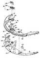
図1は、本発明の一実施例に係るロボット掃除機を示した斜視図で、図2は、カバーが除去された図1のロボット掃除機を示した図で、図3は、図1のロボット掃除機のセンサーモジュールを示した分解図である。 FIG. 1 is a perspective view illustrating a robot cleaner according to an embodiment of the present invention, FIG. 2 is a diagram illustrating the robot cleaner of FIG. 1 with a cover removed, and FIG. It is the exploded view which showed the sensor module of the robot cleaner.
図1ないし図3を参照すると、ロボット掃除機1は、カバー10及び本体20を含む。カバー10は、本体20の上部をカバーすることができる。 1 to 3, the
本体20は、床面から異物を除去する掃除ユニットと、ロボット掃除機1を走行させるホイールユニットと、ホイールユニットに動力を提供するモーターとを含むことができる。ホイールユニットは、少なくとも一つのホイールを含むことができる。ホイールは、モーターから伝達された動力を通じて回転することによって、ロボット掃除機1を走行させることができる。ホイールユニット及びモーターを駆動ユニットと称することができる。 The
ロボット掃除機1は、駆動電源を供給する電源部を含むことができる。電源部は、本体20に装着された各種部品を駆動させるための各駆動装置と電気的に連結され、各駆動装置に駆動電源を供給するバッテリーを含むことができる。バッテリーは、再充電が可能な2次バッテリーであって、本体20がドッキングステーション(図示せず)に結合されたとき、ドッキングステーションから供給された電力によって充電することができる。ロボット掃除機1は、例えば、掃除の完了後にドッキングステーションに戻ることができる。ロボット掃除機1は、掃除過程を行う前に、または掃除過程の間にドッキングステーションに結合することができる。例えば、ロボット掃除機1は、バッテリーの状態が低いと判断されるとき、例えば、一定のレベルより低いと判断されるとき、または、以下で説明するように、ロボット掃除機1の集塵装置を空にする必要があるときにドッキングステーションに結合することができる。集塵装置が空になると、例えば、ロボット掃除機1のバッテリーを充電することができる。 The
ロボット掃除機1は、電源部から駆動力を受けて回転する少なくとも一つのホイールを含むことができる。例えば、二つのホイールは、本体20の下部の中央領域の左右端に互いに対称的に配置することができる。ホイールは、走行過程でロボット掃除機1が前進、後進及び回転走行などの移動を行えるようにする。ホイールの動作により、ロボット掃除機1は床面を掃除することができる。しかし、前記開示は、二つのホイールを有するロボット掃除機1に限定されるものではなく、例えば、ロボット掃除機1は、一つのホイールまたは3つ以上のホイールを有することができる。 The
走行方向を基準にして本体20の下部前端にはキャスターをさらに設置することができる。キャスターが備えられることによって、ロボット掃除機1を走行中にも安定化させることができる。 A caster can be further installed at the lower front end of the
ロボット掃除機1は掃除ユニットを含むことができる。掃除ユニットは、本体の下側に形成された吸入口側に配列されるブラッシュユニットを含むことができる。本体20の下部には、集塵装置と連結された流入口を形成することができる。ブラッシュユニットが回転すると、床面上に積もった埃を吸入口側に誘導することができる。 The
ロボット掃除機1の本体20内には、埃の吸入のための吸入力を発生させる送風装置を備えることができる。送風装置は、吸入モーター及び送風ファンを含むことができる。吸入口側に誘導された埃は、送風装置によって集塵装置に移動させることができる。 The
ロボット掃除機1内の集塵装置に埃がある程度集まると、ロボット掃除機1は、ドッキングステーション側に移動し、ドッキングステーションとドッキングすることができる。あるいは、集塵装置は、例えば、使用者によって手動で空にすることができる。ロボット掃除機1がドッキングステーションとドッキングすると、ロボット掃除機1内の集塵装置に集まった埃をドッキングステーション内の集塵装置に吸入させることができる。ロボット掃除機1及び/またはドッキングステーション内に集まった埃は、使用者がロボット掃除機/ドッキングステーションから集塵装置を分離して捨てることもできる。その結果、ロボット掃除機1の集塵装置は、使用者によって手動で空にしたり、またはドッキングステーションの集塵装置を通じて空にすることができる。 When a certain amount of dust collects in the dust collecting device in the
本体20の内部には埃量センサーが備えられ、集塵装置内の埃の量を感知することができる。埃量センサーによって集塵装置内の埃が基準量と同じかそれ以上集まったと感知されると、制御部は、ホイールを駆動し、ロボット掃除機1を移動させてドッキングステーションとドッキングさせることができる。ロボット掃除機1がドッキングステーションとドッキングされると、ロボット掃除機1内の集塵装置に集まった埃は、ドッキングステーションに備えられた集塵装置に吸入させることができる。 A dust amount sensor is provided inside the
本体20の一側にはセンサーモジュール30を装着することができる。センサーモジュール30は、障害物感知センサーを含むことができる。障害物感知センサーは、例えば、ロボット掃除機1の前方に位置した障害物を感知することができる。障害物感知センサーによってロボット掃除機1の前方に障害物が存在すると感知されると、制御部は、ロボット掃除機1の本体2を回転させ、ロボット掃除機1の走行方向を変更することができる。その結果、ロボット掃除機1は、障害物を回避しながらも、掃除作業を行うために継続して走行することができる。 A
ロボット掃除機1の走行方向を基準にしてロボット掃除機1の前方に障害物が存在すると感知されると、ロボット掃除機1が元の場所で回転して走行方向を切り替えるので、ロボット掃除機1の特定位置が走行方向の前方に向かうようになる。したがって、センサーモジュール30または障害物感知センサーは、前方に向かうロボット掃除機1の前記特定位置に装着することができる。センサーモジュール30が装着される特定位置は、ロボット掃除機1の前方と定義することができる。しかし、センサーモジュールは、必要に応じてロボット掃除機1の他の位置に配置することができ、ロボットが走行する方向以外の方向での障害物への接近を検知するのに使用することができる。 If it is detected that there is an obstacle in front of the
本体20の前方にはセンサー窓11を装着することができる。センサー窓11は、障害物感知センサーから放出された光を透過させる素材で形成することができる。障害物感知センサーによって発光された光は、センサー窓11を通じて外部に照射することができる。図3に示したように、例えば、ロボット掃除機1の形状は実質的に円状であり得る。しかし、前記開示がこれに限定されることはなく、ロボット掃除機1は、例えば、長方形、正方形、他の多角形または幾何学的形状などのいずれかの形状であり得る。図3に示したように、センサー窓11は、一般にロボット掃除機1の形状に合わせ、本体20の前方に装着することができる。センサー窓11は、例えば、ロボット掃除機1の周辺に部分的に延長することができる。すなわち、図3に示したように、センサー窓11は、半円状を有し、円周方向にロボット掃除機の周囲に部分的に延長することができる。 A
本体20には、ロボット掃除機1の動作に関する情報が受信され、ロボット掃除機1が特定動作を行えるように情報が送信されるPCB回路部21を備えることができる。PCB回路部21は、本体20の上部に載せることができる。PCB回路部21の上部面はカバー10によってカバーすることができる。 The
以下では、本発明の一実施例に係るセンサーモジュール30の構成について詳細に説明する。 Below, the structure of the
図4は、図3のセンサーモジュールを示した分解斜視図である。図4を参照すると、センサーモジュール30は、ベースフレーム31、アッパーフレーム32及びセンサーアセンブリーを含むことができる。センサーアセンブリーは、発光素子310、受光反射鏡部34及び受光部カメラ311を含むことができる。発光素子310、受光反射鏡部34及び受光部カメラ311はベースフレーム31またはアッパーフレーム32に装着し、ベースフレーム31とアッパーフレーム32は締結部材などによって互いに結合することができる。例えば、締結部材は、スクリュー、ボルト、接着剤、ソルダーなどの一つ以上を含むことができるが、前記開示がこれに限定されることはなく、当業者によって理解され得る他のタイプの締結部材を含むことができる。センサーモジュール30は、一つのモジュールとして製造するこができる。その結果、一体に形成されたセンサーモジュール30により、ロボット掃除機1の組立容易性が向上し得る。 FIG. 4 is an exploded perspective view showing the sensor module of FIG. Referring to FIG. 4, the
ベースフレーム31には発光素子310及び受光部カメラ311を装着することができる。そして、発光素子310は複数備えることができる。図4には、四つの発光素子310が示される。しかし、前記開示がこれに限定されることはなく、ロボット掃除機1は、必要に応じて、一つ、二つ、三つまたは四つ以上の発光素子310を含むことができる。複数の発光素子310は、規則的または不規則的な間隔で配置することができる。例えば、受光部カメラ311は、アッパーフレーム32に装着される受光反射鏡部34に対応する位置に配列することができる。図4に示したように、ベースフレーム31とアッパーフレーム32は、一般にロボット掃除機1の形状に合わせ、本体20の前方に装着することができる。ベースフレーム31とアッパーフレーム32は、例えば、ロボット掃除機1の周辺に部分的に延長することができる。すなわち、図4に示したように、ベースフレーム31とアッパーフレーム32は、半円状を有し、円周方向にロボット掃除機の周囲に部分的に延長することができる。これと同様に、発光素子310、受光反射鏡部34及び受光部カメラ311は、円周または円弧方向に一定または不規則な間隔でベースフレーム31またはアッパーフレーム32に装着することができる。 A
複数の発光素子310はベースフレーム31に装着することができる。一例として、発光素子310は、赤外線を発光する赤外線発光ダイオードであり得る。発光素子310の前方には、発光素子310から発光される光をライン光に変換させる広角レンズ312を装着することができる。広角レンズ312は、発光素子310の視野角を広げることができる。すなわち、発光素子310から発光された光は、広角レンズ312によって左右により広い角度で照射されるので、一つの発光素子310から発光される光によってより広い領域に位置した障害物を感知することができる。その結果、発光素子310が一定間隔で配置された場合にも、ロボット掃除機1の前方に位置した障害物が感知されない死角地帯を回避することができる。発光素子310または広角レンズ312の一側には、ライン光を集めるレンチキュラーレンズをさらに備えることができる。そして、広角レンズ312は、発光素子310の一部または全てに備えることができる。 The plurality of
ベースフレーム31の一側にはリモコン信号受信部313を装着することができる。リモコン信号受信部313は、リモコンから信号を受けて制御部に伝送し、制御部は、ロボット掃除機1が信号に対応する動作を行うようにする。 A remote
アッパーフレーム32の前方一側には多数のスリット321を形成することができる。発光素子310は、スリット321に対応する位置に備えることができる。発光素子310は、スリット321の後方または内側に配列することができ、発光素子310から発光される光は、スリット321を通じてロボット掃除機1の前方に照射することができる。 A number of
スリット321は、発光素子310から発光された光をロボット掃除機1の前方に照射するように集める役割をすることができる。さらに、発光素子310の上側は、光が遮光されるようにスリット321によってカバーすることができる。発光素子310の上側が遮光されることによって、発光素子310から発光された光がセンサー窓11の内側表面から反射され、発光素子310の上部に位置した受光反射鏡340に入射されることを防止し、その結果、ロボット掃除機1の前方に実質的に存在しない障害物の誤感知を防止することができる。 The
アッパーフレーム32には、アッパーフレーム32から上部に突出したマウント部330を備えることができる。マウント部330は、アッパーフレーム32と射出成形を通じて一体に形成することもでき、または、別個に製造してアッパーフレーム32に装着することもできる。マウント部330の上側には、受光反射鏡340が装着される載置部332を備えることができる。載置部332には、受光反射鏡340が通過するホール331を形成することができる。 The
受光反射鏡340にはレンズフレーム341を装着することができる。レンズフレーム341は載置部332上に載せることができる。このとき、受光反射鏡340は、ホール331を通じて載置部332から下部に突出し得る。その結果、アッパーフレーム32は、受光反射鏡340が露出するように装着することができる。例えば、図4と図5に示したように、受光反射鏡340の底部は、物体または障害物Tに反射してセンサー窓11を通過する光が受光反射鏡340の露出部に入射されるように、マウント部330の載置部332の下部に配置することができる。 A lens frame 341 can be attached to the light receiving / reflecting
受光反射鏡340の下部に位置したアッパーフレーム32にはホール320を備えることができる。ホール320の下部またはホール320の内側には受光部カメラ311を備えることができる。受光反射鏡340に反射光が入射されると、受光部カメラ311は、受光反射鏡340に入射された反射光に関する情報を受信して制御部に伝送することができる。 The
受光反射鏡340は、例えば、図5に示したように、円錐状に形成することができる。レンズフレーム341が載置部332に載せられ、受光反射鏡340がアッパーフレーム32に装着されると、受光反射鏡340は、円錐の底面が上部に向かい、円錐の頂点が下部に向かうように配列することができる。受光反射鏡340または受光部カメラ311には、受信部の分解能を改善させるレンチキュラーレンズをさらに備えることができる。 The light receiving / reflecting
マウント部330にはドッキングセンサー37を装着することができる。ドッキングセンサー37は、ロボット掃除機1のドッキングステーション(図示せず)に備えられた信号受信部に信号を送信することができる。例えば、ロボット掃除機1内に集まった埃を除去する必要があったり、ロボット掃除機1を充電する必要があるとき、ドッキングセンサー37によってロボット掃除機1の位置を感知し、ロボット掃除機1をドッキングステーションに案内することができる。 A docking sensor 37 can be attached to the
マウント部330にはタレット36を装着することができる。タレット36は、センサー装着部360及び上部カバー361を含むことができる。センサー装着部360はマウント部330に装着することができる。センサー装着部360には、ドッキングセンサー37が挿入されるホール362を形成することができる。ドッキングセンサー37は、ホール362に挿入して固定することができる。上部カバー361は、センサー装着部360の上部をカバーするように装着され、例えば、ドッキングセンサー37が外部環境に露出しないようにする。 A
センサー装着部360が受光反射鏡部34の上側に位置する場合、受光反射鏡340とドッキングセンサー37とを離隔させるために受光反射鏡部34とドッキングセンサー37との間にブラケット35を介在させることができる。ブラケット35には突出リブ350を備えることができる。ブラケット35は、マウント部330または載置部332に装着し、受光反射鏡部34とドッキングセンサー37との間に位置し、突出リブ350によって受光反射鏡部34とドッキングセンサー37とを離隔させることができる。 When the
前記のような構造により、センサーモジュール30は、センサーアセンブリー、リモコン信号受信部313及びドッキングセンサー37を含むことができ、これら構成要素の二つ以上は一つのユニットとしてモジュール化(または一体に形成)することができる。その結果、ロボット掃除機1の組み立て効率が向上し得る。 Due to the above-described structure, the
図5は、図3のセンサーモジュールによる障害物の感知を示した概略図である。図5を参照すると、センサーモジュール30の発光素子310から発光された光は、ロボット掃除機1の前方に位置した障害物Tの表面Pから反射され、受光反射鏡340のP'地点に入射され得る。受光反射鏡340に入射された光のイメージは、受光反射鏡340の下部に位置した受光部カメラ311に入力され、受光部カメラ311は、受光反射鏡340に入射された光のイメージに関する情報を制御部(図示せず)に伝送することができる。その結果、ロボット掃除機1の前方に障害物Tが存在することを感知することができる。 FIG. 5 is a schematic diagram illustrating obstacle detection by the sensor module of FIG. Referring to FIG. 5, the light emitted from the
一方、発光素子310から発光された光は、センサー窓11の内側面fから反射させることができる。センサー窓11の内側面fから反射された光が、スリット321を形成するアッパーフレーム32の上部内側面によって受光反射鏡340側に入射されることを防止することができる。その結果、センサー窓11の内側面fから反射された光によって障害物の誤感知が生じることを防止することができる。 On the other hand, the light emitted from the
ここで開示した各実施例においては、アッパーフレーム32から上部に突出するマウント部330上に受光反射鏡340を配列することができ、受光反射鏡340の下部に受光カメラ311を配列することができる。発光素子310から発光された光は反射されて受光反射鏡340に入射され、受光反射鏡340に入射された光のイメージに関する情報を制御部(図示せず)に伝送することができる。 In each of the embodiments disclosed herein, the light receiving / reflecting
あるいは、アッパーフレーム32から上部に突出するマウント部330に受光カメラ311が配列または配置され、発光素子310から発光された光が反射されて受光カメラ311に直接入射されることも可能である。この場合、発光素子310から発光された光が反射されてから受光カメラ311に入射され、受光カメラ311は、入射された光のイメージに関する情報を制御部(図示せず)に伝送することができる。 Alternatively, the
この場合にも、発光素子310から発光された光は、スリット321を通じてロボット掃除機1の前方に照射することができ、発光素子310の上側を遮光することができる。発光素子310の上側が遮光されることによって、発光素子310から発光された光がセンサー窓11の内側表面から反射され、発光素子310の上部に位置した受光カメラ311に入射されることを防止することができる。その結果、発光素子310から発光された光は、スリット321を通じてライン光の形態でロボット掃除機1から前方に照射することができ、ロボット掃除機1の前方に存在しない障害物の誤感知を防止することができる。 Also in this case, the light emitted from the
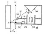
図6は、本発明の他の実施例に係るセンサーモジュールの一部を示した図で、図7は、図6のセンサーモジュールを示した断面図で、図8は、図6のセンサーモジュールによる障害物の感知を示した概略図である。 6 is a view showing a part of a sensor module according to another embodiment of the present invention, FIG. 7 is a sectional view showing the sensor module of FIG. 6, and FIG. 8 is based on the sensor module of FIG. It is the schematic which showed the detection of the obstruction.
図6及び図7を参照すると、本発明の他の実施例に係るセンサーモジュール30のアッパーフレーム32には段差部322を形成することができる。段差部322は、アッパーフレーム32の前方上部面に形成することができる。詳細には、段差部322は、スリット321を形成するアッパーフレーム32の上側面に形成することができる。段差部322が形成されることによって、ロボット掃除機1に近接した障害物から反射された光が、スリット321を形成するアッパーフレーム32の上側面によって干渉されて受光反射鏡340に入射されないことを防止することができる。 6 and 7, a stepped
図8を参照すると、ロボット掃除機1の前方に近接するように位置した物体または障害物Tが存在するとき、発光素子310から発光された光は障害物Tに照射され、障害物Tの表面Rから反射された光は、受光反射鏡340のR'地点に受光され得る。図8に示したように、アッパーフレーム32の前方上側面に段差部322が形成されているので、スリット321を形成するアッパーフレーム32の上側面によって障害物Tの表面Rから反射された光の経路が妨害されない。その結果、アッパーフレーム32が発光素子310の装着位置から上側前方に突出したとしても、ロボット掃除機1に近接するように位置した障害物Tを正確に感知することができる。すなわち、段差部322は、センサー窓11に向かって下向きの傾斜または角度でアッパーフレーム32から延長することができる。比較として、図5の実施例においては、段差部322を含んでおらず、アッパーフレーム32は、センサー窓11に向かって発光素子310の上部に延長することができる。 Referring to FIG. 8, when an object or an obstacle T located close to the front of the
障害物Tとロボット掃除機1との距離が減少するほど、受光反射鏡340の頂点と、障害物Tから反射された光が入射される地点との間の距離も減少する。図5及び図8を参照すると、図5に示した障害物Tとロボット掃除機1との間の距離L1は、図8に示した障害物Tとロボット掃除機1との間の距離L2より大きい。図5に示した障害物Tから反射された光は、受光反射鏡340のP'地点に入射され得る。受光反射鏡340の頂点AとP'地点との間の距離はD1と定義することができる。図8に示した障害物Tから反射された光は、受光反射鏡340のR'地点に入射され得る。受光反射鏡340の頂点AとR'地点との間の距離はD2と定義することができる。ここで、D1はD2より大きい。すなわち、ロボット掃除機1と障害物Tとの間の距離が増加するほど、受光反射鏡340の頂点Aと受光反射鏡340への入射地点との間の距離が増加するという関係を成立または理解することができる。そのため、受光反射鏡340の頂点Aと、障害物Tから反射された光が入射される地点との間の距離によって、ロボット掃除機1と障害物Tとの間の距離を測定することができる。受光部カメラ311は、受光反射鏡340に入射された光に関する情報を制御部に伝送し、制御部は、前記光が入射された位置に関する情報を用いて障害物Tの位置を測定し、ロボット掃除機1の移動方向などを調節することができる。 As the distance between the obstacle T and the
図9は、本発明の更に他の実施例に係るセンサーモジュールを示した図である。図9を参照すると、本発明の更に他の実施例のセンサーモジュール30は、ベースフレーム31、遮光パネル38及びセンサー窓11を含むことができる。ベースフレーム31は遮光パネル38と結合することができ、センサー窓11はベースフレーム31または遮光パネル38と結合することができる。 FIG. 9 is a view showing a sensor module according to still another embodiment of the present invention. Referring to FIG. 9, the
本発明の一実施例のセンサーモジュール30と同様に、ベースフレーム31には発光素子310及び受光部カメラ311を装着することができ、遮光パネル38には受光反射鏡部34及びドッキングセンサー37を装着することができる。 Similarly to the
遮光パネル38は、ベースフレーム31に装着された発光素子310の上部に位置し得る。遮光パネル38は、発光素子310から発光された光がセンサー窓11の内側表面から反射されて受光反射鏡340に入射されることを防止することができる。その結果、ロボット掃除機1の前方に障害物が存在すると誤感知されることを防止することができる。一方、遮光パネル38には、本発明の一実施例のアッパーフレーム32に形成された段差部322と同様に、前方上部面に段差部を形成することもできる。その結果、ロボット掃除機1に近接した障害物を正確に感知することができる。 The
センサー窓11はモジュール化することができる。すなわち、センサーモジュール30はセンサー窓11を含むことができる。したがって、ロボット掃除機1の組み立て時にセンサー窓11を別途に連結する必要がないので、ロボット掃除機1の組み立て効率を向上させることができる。 The
センサー窓11は遮光パネル38と一体化することができる。すなわち、センサーモジュール30と遮光パネル38は、ロボット掃除機1に一つのユニットとして一体化して備えることができる。センサーモジュール30と遮光パネル38がロボット掃除機1に一体化されて備えられることによって、ロボット掃除機の組み立て効率を高めることができる。 The
発光素子310から発光された光が、センサー窓11の内側表面から反射されて受光反射鏡340に入射されることを防止するために備えられたアッパーフレーム32のスリット321または遮光パネル38は、遮光部と定義したり称することができる。 The
障害物を感知するモジュール化されたセンサーがロボット掃除機1に装着されることによって、ロボット掃除機1の組み立て効率を向上させることができる。さらに、センサーモジュールに遮光部が備えられることによって、発光素子から発光された光が、センサー窓の内側から反射されて受光反射鏡に入射されることを防止することができ、その結果、障害物の誤感知を防止することができる。遮光部の前方上部面に段差部が形成されると、ロボット掃除機に近接するように位置した障害物をより正確に感知することができる。すなわち、段差部は、段差部を含まないロボット掃除機の実施例と比べると、物体がより近い距離でロボット掃除機によって感知されるようにする。ロボット掃除機がより近い距離で物体を感知できるので、ロボット掃除機は、物体との接触なく各物体により近接するように動作することができ、物体からの分離を維持した状態でより完璧に掃除を行うことができる。 Assembling efficiency of the
上述した各実施例に係るロボット掃除機は、一つ以上のプロセッサを用いることができる。例えば、ロボット掃除機の制御部は、処理装置として具体化することができ、例えば、プロセッサ、中央処理装置(CPU)、グラフィックス・プロセッシング・ユニット(GPU)、デジタル・シグナル・プロセッサ(DSP)、マイクロコンピューター、フィールド・プログラマブル・アレイ、プログラマブル・ロジック・ユニット、特定用途向け集積回路(ASIC)、マイクロプロセッサ、または定義された方式で指示または動作に応答したり、指示または動作を行える他の装置などの一つ以上の汎用または専用コンピューターを用いて実行することができる。 The robot cleaner according to each embodiment described above can use one or more processors. For example, the controller of the robot cleaner can be embodied as a processing device, such as a processor, a central processing unit (CPU), a graphics processing unit (GPU), a digital signal processor (DSP), Microcomputers, field programmable arrays, programmable logic units, application specific integrated circuits (ASICs), microprocessors, or other devices that can respond to or perform instructions or actions in a defined manner Can be implemented using one or more general purpose or special purpose computers.
本発明の各実施例が図示及び説明されたが、当業者によって発明の原理及び精神から逸脱しない範囲でこれら実施例を変更可能であることが分かるだろう。本発明の範囲は、特許請求の範囲及びこれらの均等物で定義される。 While embodiments of the invention have been illustrated and described, it will be appreciated by those skilled in the art that the embodiments can be modified without departing from the principles and spirit of the invention. The scope of the invention is defined by the claims and their equivalents.
1 ロボット掃除機
11 センサー窓
20 本体
30 センサーモジュール
31 ベースフレーム
32 アッパーフレーム
310 発光素子
321 スリット
340 受光反射鏡DESCRIPTION OF
Claims (15)
Translated fromJapanese前記本体の上部をカバーするカバー;
前記本体に装着されて障害物を感知する障害物感知センサーを含むセンサーモジュール;及び
前記センサーモジュールの一側に備えられるセンサー窓;を含み、
前記センサーモジュールは、前記センサー窓を通過して光を照射する発光素子;
前記発光素子から発光されてから障害物から反射される光が入射される受光反射鏡;及び
前記発光素子と前記受光反射鏡との間に介在し、前記発光素子から発光された光が前記センサー窓の内側表面から反射されて前記受光反射鏡に入射されることを遮断する遮光部;を含むロボット掃除機。A main body including a cleaning unit that removes foreign matter from the floor, and a wheel unit that rotates through power transmitted from a motor;
A cover covering an upper part of the main body;
A sensor module including an obstacle detection sensor mounted on the main body to detect an obstacle; and a sensor window provided on one side of the sensor module;
The sensor module emits light through the sensor window;
A light-receiving / reflecting mirror that receives light that is emitted from the light-emitting element and then reflected from an obstacle; and light that is emitted from the light-emitting element is interposed between the light-emitting element and the light-receiving / reflecting mirror. A robot cleaner including: a light shielding unit that blocks light from being reflected from an inner surface of the window and entering the light receiving reflector.
Applications Claiming Priority (2)
| Application Number | Priority Date | Filing Date | Title |
|---|---|---|---|
| KR1020130039847AKR102020210B1 (en) | 2013-04-11 | 2013-04-11 | Sensor module and robot cleaner having the same |
| KR10-2013-0039847 | 2013-04-11 |
Publications (1)
| Publication Number | Publication Date |
|---|---|
| JP2014204984Atrue JP2014204984A (en) | 2014-10-30 |
Family
ID=50391040
Family Applications (1)
| Application Number | Title | Priority Date | Filing Date |
|---|---|---|---|
| JP2014079986APendingJP2014204984A (en) | 2013-04-11 | 2014-04-09 | Sensor module and robot cleaner including the same |
Country Status (5)
| Country | Link |
|---|---|
| US (2) | US9918603B2 (en) |
| EP (1) | EP2790079B1 (en) |
| JP (1) | JP2014204984A (en) |
| KR (1) | KR102020210B1 (en) |
| CN (1) | CN104095587A (en) |
Cited By (2)
| Publication number | Priority date | Publication date | Assignee | Title |
|---|---|---|---|---|
| JP2018519959A (en)* | 2015-07-17 | 2018-07-26 | エルジー エレクトロニクス インコーポレイティド | Robot vacuum cleaner |
| JP2022524462A (en)* | 2019-03-11 | 2022-05-02 | 美智縦横科技有限責任公司 | Detection method and control method for detection assembly, robot vacuum cleaner and its track conditions |
Families Citing this family (33)
| Publication number | Priority date | Publication date | Assignee | Title |
|---|---|---|---|---|
| GB2529847B (en)* | 2014-09-03 | 2018-12-19 | Dyson Technology Ltd | A mobile Robot with Independently Adjustable Light Sources |
| GB2529846B (en) | 2014-09-03 | 2019-02-20 | Dyson Technology Ltd | Illumination Control of a Vision System for a Mobile Robot |
| KR102314637B1 (en)* | 2015-03-23 | 2021-10-18 | 엘지전자 주식회사 | Robot cleaner, and robot cleaning system |
| CN105511477A (en)* | 2016-02-16 | 2016-04-20 | 江苏美的清洁电器股份有限公司 | Cleaning robot system and cleaning robot |
| CN105824313A (en)* | 2016-03-15 | 2016-08-03 | 深圳市华讯方舟科技有限公司 | Barrier avoidance method and device |
| CN105982611A (en)* | 2016-04-14 | 2016-10-05 | 北京小米移动软件有限公司 | Self-cleaning equipment |
| TWI653964B (en) | 2016-05-17 | 2019-03-21 | Lg電子股份有限公司 | Mobile robot and its control method |
| TWI639021B (en) | 2016-05-17 | 2018-10-21 | 南韓商Lg電子股份有限公司 | Mobile robot and method of controlling the same |
| CN207979622U (en) | 2016-05-17 | 2018-10-19 | Lg电子株式会社 | Robot cleaner |
| US10213082B2 (en)* | 2016-08-30 | 2019-02-26 | Samsung Electronics Co., Ltd. | Robot cleaner |
| KR102601463B1 (en) | 2016-10-28 | 2023-11-14 | 삼성전자주식회사 | Robot cleaner and driving method thereof |
| US10962647B2 (en) | 2016-11-30 | 2021-03-30 | Yujin Robot Co., Ltd. | Lidar apparatus based on time of flight and moving object |
| WO2019039728A1 (en)* | 2017-08-21 | 2019-02-28 | (주)유진로봇 | Ultra-small three-dimensional scanning lidar sensor |
| EP3678902B1 (en) | 2017-09-07 | 2023-06-21 | SharkNinja Operating LLC | Robotic cleaner |
| US11579298B2 (en) | 2017-09-20 | 2023-02-14 | Yujin Robot Co., Ltd. | Hybrid sensor and compact Lidar sensor |
| CN107898377A (en)* | 2017-09-26 | 2018-04-13 | 中国科学院深圳先进技术研究院 | A kind of curtain method for cleaning and system |
| WO2019090649A1 (en) | 2017-11-09 | 2019-05-16 | Oppo广东移动通信有限公司 | Access control method, device, and computer-readable medium and system |
| US11874399B2 (en) | 2018-05-16 | 2024-01-16 | Yujin Robot Co., Ltd. | 3D scanning LIDAR sensor |
| DE102018209286A1 (en)* | 2018-06-11 | 2019-12-12 | Continental Automotive Gmbh | Optical or opto-electronic device with a cleaning device |
| CN211933894U (en) | 2018-08-01 | 2020-11-17 | 尚科宁家运营有限公司 | Robot vacuum cleaner |
| CN111766589A (en)* | 2019-03-12 | 2020-10-13 | 江苏美的清洁电器股份有限公司 | Detection assembly, floor sweeping robot and method and system for detecting walking road conditions of floor sweeping robot |
| WO2020191688A1 (en)* | 2019-03-28 | 2020-10-01 | 深圳市大疆创新科技有限公司 | Sensing module and robot |
| WO2020242959A1 (en) | 2019-05-24 | 2020-12-03 | Sharkninja Operating Llc | Obstacle sensor system and autonomous device using the same |
| DE102019122060A1 (en)* | 2019-08-16 | 2021-02-18 | Vorwerk & Co. Interholding Gmbh | Base station for stationary emptying of a dirty area of a mobile cleaning device, cleaning system and process |
| CN112596508B (en)* | 2019-08-29 | 2022-04-12 | 美智纵横科技有限责任公司 | Control method and device of sensor and storage medium |
| CN110764071A (en)* | 2019-10-29 | 2020-02-07 | 北京百度网讯科技有限公司 | Lidar protective cover and Lidar |
| CN210927761U (en)* | 2020-01-10 | 2020-07-03 | 北京石头世纪科技股份有限公司 | Intelligent cleaning equipment |
| CN112515544B (en)* | 2020-09-11 | 2025-07-11 | 深圳银星智能集团股份有限公司 | Intelligent Robots |
| CN214259197U (en)* | 2020-11-25 | 2021-09-24 | 深圳市杉川机器人有限公司 | TOF module, camera subassembly and robot of sweeping floor |
| CN112754357A (en)* | 2020-12-09 | 2021-05-07 | 深圳市云视机器人有限公司 | Cleaning equipment |
| CN112540374A (en)* | 2020-12-24 | 2021-03-23 | 珠海格力电器股份有限公司 | Cliff sensing device and mobile robot |
| KR102500525B1 (en)* | 2021-07-14 | 2023-02-16 | 엘지전자 주식회사 | Moving robot |
| CN114305220B (en)* | 2021-12-16 | 2024-03-19 | 美智纵横科技有限责任公司 | Detection device and robot sweeps floor |
Family Cites Families (14)
| Publication number | Priority date | Publication date | Assignee | Title |
|---|---|---|---|---|
| WO1993003399A1 (en)* | 1991-08-07 | 1993-02-18 | Aktiebolaget Electrolux | Obstacle detecting assembly |
| JP3202856B2 (en)* | 1993-12-28 | 2001-08-27 | 株式会社リコー | Image reading device |
| US6142252A (en)* | 1996-07-11 | 2000-11-07 | Minolta Co., Ltd. | Autonomous vehicle that runs while recognizing work area configuration, and method of selecting route |
| JP2004237075A (en)* | 2003-02-06 | 2004-08-26 | Samsung Kwangju Electronics Co Ltd | A robot cleaner system having an external charging device and a method of connecting an external charging device of the robot cleaner. |
| KR100474086B1 (en) | 2003-07-24 | 2005-03-14 | 삼성광주전자 주식회사 | Apparatus for opening and closing lens unit of camera, and robot-cleaner having one |
| JP2006010506A (en)* | 2004-06-25 | 2006-01-12 | Sharp Corp | Optical ranging sensor and self-propelled vacuum cleaner |
| KR100638220B1 (en) | 2005-04-23 | 2006-10-27 | 엘지전자 주식회사 | Position sensing device of traveling robot and robot cleaner equipped with it |
| US7614563B1 (en)* | 2005-12-29 | 2009-11-10 | Cognex Technology And Investment Corporation | System and method for providing diffuse illumination in a symbology reader |
| US8716665B2 (en)* | 2009-09-10 | 2014-05-06 | Avago Technologies General Ip (Singapore) Pte. Ltd. | Compact optical proximity sensor with ball grid array and windowed substrate |
| KR101487778B1 (en)* | 2010-05-11 | 2015-01-29 | 삼성전자 주식회사 | Sensing system and moving robot having the same |
| KR20120140176A (en)* | 2011-06-20 | 2012-12-28 | (주)차바이오앤디오스텍 | Reflection optical system for object recognition and moving robot using the same |
| KR20130034573A (en)* | 2011-09-28 | 2013-04-05 | 삼성전자주식회사 | Fencing sense apparatus and robot cleaner having the same |
| TWI467777B (en)* | 2012-06-06 | 2015-01-01 | Pixart Imaging Inc | Optical device package structure |
| US9020641B2 (en)* | 2012-06-07 | 2015-04-28 | Samsung Electronics Co., Ltd. | Obstacle sensing module and cleaning robot including the same |
- 2013
- 2013-04-11KRKR1020130039847Apatent/KR102020210B1/enactiveActive
- 2014
- 2014-03-27EPEP14162050.0Apatent/EP2790079B1/enactiveActive
- 2014-04-08USUS14/247,819patent/US9918603B2/enactiveActive
- 2014-04-09JPJP2014079986Apatent/JP2014204984A/enactivePending
- 2014-04-11CNCN201410144830.1Apatent/CN104095587A/enactivePending
- 2018
- 2018-01-31USUS15/884,982patent/US11103115B2/enactiveActive
Cited By (4)
| Publication number | Priority date | Publication date | Assignee | Title |
|---|---|---|---|---|
| JP2018519959A (en)* | 2015-07-17 | 2018-07-26 | エルジー エレクトロニクス インコーポレイティド | Robot vacuum cleaner |
| US10588474B2 (en) | 2015-07-17 | 2020-03-17 | Lg Electronics Inc. | Robot cleaner |
| JP2022524462A (en)* | 2019-03-11 | 2022-05-02 | 美智縦横科技有限責任公司 | Detection method and control method for detection assembly, robot vacuum cleaner and its track conditions |
| JP7221416B2 (en) | 2019-03-11 | 2023-02-13 | 美智縦横科技有限責任公司 | ROBOT VACUUM CLEANER AND METHOD OF DETECTING AND CONTROLLING ROBOT PATH CONDITION THEREOF |
Also Published As
| Publication number | Publication date |
|---|---|
| EP2790079A2 (en) | 2014-10-15 |
| US9918603B2 (en) | 2018-03-20 |
| EP2790079B1 (en) | 2022-02-16 |
| EP2790079A3 (en) | 2017-08-16 |
| US20180177371A1 (en) | 2018-06-28 |
| US20140304937A1 (en) | 2014-10-16 |
| US11103115B2 (en) | 2021-08-31 |
| KR102020210B1 (en) | 2019-11-05 |
| CN104095587A (en) | 2014-10-15 |
| KR20140123174A (en) | 2014-10-22 |
Similar Documents
| Publication | Publication Date | Title |
|---|---|---|
| JP2014204984A (en) | Sensor module and robot cleaner including the same | |
| US20240126291A1 (en) | Autonomous cleaner | |
| US11547263B2 (en) | Autonomous cleaner | |
| US10362916B2 (en) | Autonomous cleaner | |
| US9864914B2 (en) | Lens assembly, obstacle detecting unit using the same, and moving robot having the same | |
| US20170332853A1 (en) | Autonomous cleaner | |
| US10481611B2 (en) | Autonomous cleaner | |
| JP6571051B2 (en) | Autonomous traveling vacuum cleaner system and charging stand | |
| US10524628B2 (en) | Autonomous cleaner | |
| KR102045002B1 (en) | Robot cleaner | |
| JP6626723B2 (en) | A moving object that moves on the floor | |
| JP7672052B2 (en) | Self-propelled robot | |
| KR20220003780A (en) | Charging Device For Robot Cleaner and Controlling Method of Robot Cleaner using the same | |
| EP4201289A2 (en) | Robot cleaner |