JP2014202938A - Image forming apparatus and image forming method - Google Patents
Image forming apparatus and image forming methodDownload PDFInfo
- Publication number
- JP2014202938A JP2014202938AJP2013079422AJP2013079422AJP2014202938AJP 2014202938 AJP2014202938 AJP 2014202938AJP 2013079422 AJP2013079422 AJP 2013079422AJP 2013079422 AJP2013079422 AJP 2013079422AJP 2014202938 AJP2014202938 AJP 2014202938A
- Authority
- JP
- Japan
- Prior art keywords
- light
- image
- color
- glossiness
- image forming
- Prior art date
- Legal status (The legal status is an assumption and is not a legal conclusion. Google has not performed a legal analysis and makes no representation as to the accuracy of the status listed.)
- Pending
Links
Images


Classifications
- G—PHYSICS
- G03—PHOTOGRAPHY; CINEMATOGRAPHY; ANALOGOUS TECHNIQUES USING WAVES OTHER THAN OPTICAL WAVES; ELECTROGRAPHY; HOLOGRAPHY
- G03G—ELECTROGRAPHY; ELECTROPHOTOGRAPHY; MAGNETOGRAPHY
- G03G15/00—Apparatus for electrographic processes using a charge pattern
- G03G15/50—Machine control of apparatus for electrographic processes using a charge pattern, e.g. regulating differents parts of the machine, multimode copiers, microprocessor control
- G03G15/5062—Machine control of apparatus for electrographic processes using a charge pattern, e.g. regulating differents parts of the machine, multimode copiers, microprocessor control by measuring the characteristics of an image on the copy material
Landscapes
- Engineering & Computer Science (AREA)
- Microelectronics & Electronic Packaging (AREA)
- Physics & Mathematics (AREA)
- General Physics & Mathematics (AREA)
- Control Or Security For Electrophotography (AREA)
- Color Electrophotography (AREA)
- Investigating Or Analysing Materials By Optical Means (AREA)
Abstract
Description
Translated fromJapanese本発明は、画像形成装置及び画像形成方法に関する。 The present invention relates to an image forming apparatus and an image forming method.
複写機、プリンタ等の画像形成装置では紙上に色材を付着させて画像を形成しており、色材の付着面積を変えることによって複数階調を表現している(面積階調)。そのため、紙白部の光沢度と、色材が付着された画像部の光沢度とが異なると、同一画像内においても階調によって光沢差が生じ、光沢均一性を損なってしまう。 In an image forming apparatus such as a copying machine or a printer, an image is formed by attaching a color material on paper, and a plurality of gradations are expressed by changing the adhesion area of the color material (area gradation). For this reason, if the glossiness of the white portion of the paper and the glossiness of the image portion to which the color material is attached are different, a gloss difference is produced depending on the gradation even in the same image, and gloss uniformity is impaired.
一般に光沢均一性を高めるためには、紙種ごとに紙白部の光沢度と、画像部の光沢度とを予め把握しておき、使用する紙種に応じて紙白部の光沢度と、画像部の光沢度との差が小さくなるように画像部の光沢度を制御している。画像部の光沢度の制御方法としては、例えば、色材の定着温度や定着速度を制御し、色材表面の平滑度を変える方法や、透明色材で画像を形成して光沢を制御する方法がある。 In general, in order to improve gloss uniformity, the glossiness of the white portion of the paper and the glossiness of the image portion are grasped in advance for each paper type, and the glossiness of the white portion of the paper according to the paper type used, The glossiness of the image portion is controlled so that the difference from the glossiness of the image portion becomes small. As a method for controlling the glossiness of the image area, for example, a method of changing the smoothness of the color material surface by controlling the fixing temperature and fixing speed of the color material, or a method of controlling the gloss by forming an image with a transparent color material There is.
しかしながら、近年、印刷物の質感の向上や光沢性の向上のため、使用される紙種が多様化しており、全ての紙種について、紙白部の光沢度と、画像部の光沢度とを予め取得することは困難であるという問題があった。この問題を解決する技術として、画像形成装置内に光沢度測定器を具備し、定着の後工程において画像部の光沢度を検出し、光沢均一性が向上するように画像形成条件を設定する技術が公開されている(例えば、特許文献1、特許文献2を参照)。 However, in recent years, the types of paper used have been diversified in order to improve the texture and glossiness of printed matter. For all paper types, the glossiness of the white portion of the paper and the glossiness of the image portion are set in advance. There was a problem that it was difficult to obtain. As a technology to solve this problem, a glossiness measuring device is provided in the image forming apparatus, and the glossiness of the image portion is detected in the post-fixing process and the image forming conditions are set so as to improve gloss uniformity. (For example, refer to Patent Document 1 and Patent Document 2).
特許文献1には、画像中の最大光沢度と、画像中の最小光沢度との差である光沢度差が所定値以下となるように、画像形成条件を設定することで、同一画像面内における光沢が均一で良好な印象を与えるフルカラー画像を形成する画像形成装置が記載されている。 Japanese Patent Application Laid-Open No. 2004-228688 sets the image forming conditions so that the difference in glossiness, which is the difference between the maximum glossiness in the image and the minimum glossiness in the image, is equal to or less than a predetermined value. An image forming apparatus for forming a full-color image that gives a good impression with a uniform gloss is described.
なお、特許文献1に記載の光沢度測定方法として「JISZ8741:1997 鏡面光沢度 - 測定方法」に規定の方法が記載されている。すなわち、測定面の法線に対し、入射角θと、受光角θ’とが等しくなるように、光源および受光部を設置し、光源から光を入射させ、正反射した光を受光部にて測定する方法である。特許文献1の実施例においては、入射角θを60度として光沢度の検出を行っている。 As a glossiness measuring method described in Patent Document 1, a method defined in “JISZ8741: 1997 Specular Glossiness—Measurement Method” is described. That is, the light source and the light receiving unit are installed so that the incident angle θ is equal to the light receiving angle θ ′ with respect to the normal of the measurement surface, light is incident from the light source, and the specularly reflected light is received by the light receiving unit. It is a method of measuring. In the example of Patent Document 1, glossiness is detected with an incident angle θ of 60 degrees.
特許文献2には、基準画像の大きな領域で測定した光沢度を基準に出力画像の光沢度を制御することにより、光沢度の変化による画質の変動を最小限に抑えた画像を出力できる画像形成システムが記載されている。特許文献2は、光沢度測定装置と、測定面との距離を大きくした場合であっても、入射角θを20度以下とすることで、精度の高い光沢度の測定が可能となる光沢度測定方法を提案している。 Japanese Patent Application Laid-Open No. 2005-228867 describes image formation that can output an image with minimal fluctuation in image quality due to a change in glossiness by controlling the glossiness of an output image based on the glossiness measured in a large area of the reference image. The system is described.
しかしながら、上記の先行技術は、以下に述べる問題を有している。 However, the above prior art has the following problems.
特許文献1に記載の方法を使用して、画像形成装置内において用紙搬送中に光沢度の測定を行う場合には、光沢度測定装置と、測定面とを接触させることができない。従って、紙の浮き若しくはうねり又は測定面の振動等によって光沢度測定装置と、測定面との間の距離が変動する。そのため、特許文献1に記載の光沢度の測定方法(60度光沢度)では、測定面で正反射方向に反射した光の中心と、受光部の中心とのずれ幅が大きく、光沢度を安定して測定することができないという問題があった。 When using the method described in Patent Document 1 to measure the glossiness during paper conveyance in the image forming apparatus, the glossiness measuring apparatus cannot be brought into contact with the measurement surface. Accordingly, the distance between the glossiness measuring device and the measurement surface varies due to floating or undulation of the paper or vibration of the measurement surface. Therefore, in the glossiness measurement method described in Patent Document 1 (60-degree glossiness), the deviation between the center of the light reflected in the regular reflection direction on the measurement surface and the center of the light receiving unit is large, and the glossiness is stabilized. There was a problem that it could not be measured.
一方、特許文献2に記載の光沢度の測定方法では、入射角θを20度以下とすることで、光沢度測定装置と、測定面との間の距離に変動があっても、精度の高い光沢度の測定を可能としている。しかしながら、入射角θを浅い角度とする場合、画像内部で吸収、散乱されて画像表面から放出される拡散反射光により、光沢度の測定精度が低下する問題がある。特に、紙白部と、画像部とにおける拡散反射光の差が大きい色材の場合には、階調による拡散光量の変化が光沢度の測定値に影響し、光沢度を精度良く測定することができないという問題があった。 On the other hand, in the glossiness measuring method described in
本発明は、上記の問題を鑑みてなされたものである。本発明の目的は、画像の光沢度を安定して精度よく取得することができる画像形成装置を提供することである。 The present invention has been made in view of the above problems. An object of the present invention is to provide an image forming apparatus that can stably and accurately acquire the glossiness of an image.
なお、本明細書では、測定面の法線から遠い角度の入射角を「浅い」入射角、測定面の法線に近い角度の入射角を「深い」入射角と表記する。 In the present specification, an incident angle that is far from the normal of the measurement surface is referred to as a “shallow” incident angle, and an incident angle that is close to the normal of the measurement surface is referred to as a “deep” incident angle.
本発明は、複数の色の色材を用いて画像を形成する画像形成装置であって、前記複数の色の色材のうちの一部の色の色材で形成した画像の正反射光を測定する正反射光測定手段と、前記正反射光測定手段により測定した前記正反射光の強度に基づいて、光沢度を決定する光沢度決定手段とを備えることを特徴とする。 The present invention is an image forming apparatus that forms an image using color materials of a plurality of colors, and the regular reflection light of an image formed with a color material of a part of the plurality of color materials. It comprises a regular reflection light measuring means for measuring, and a glossiness determining means for determining a glossiness based on the intensity of the regular reflection light measured by the regular reflection light measuring means.
本発明によれば、安定して精度良く光沢度を測定することができ、精度の高い光沢均一化を伴う光沢制御が可能となる。 According to the present invention, it is possible to measure glossiness stably and accurately, and gloss control with high gloss uniformity is possible.
以下、図面を参照しながら、本発明の実施形態を説明する。本明細書では、同一の参照番号は、同一の要素を指し示すので留意されたい。 Hereinafter, embodiments of the present invention will be described with reference to the drawings. It should be noted that in the present specification, the same reference numerals indicate the same elements.
なお、以下に説明する実施形態では、電子写真記録方式を用いたプリンタを例に挙げて説明するが、他の記録方式であっても紙の表面に色材を付着させて画像を形成するプリンタであれば本発明を適用可能である。また、プリンタでなくともプリンタを含む装置であれば、同様に本発明を適用可能である。 In the embodiment described below, a printer using an electrophotographic recording method will be described as an example. However, a printer that forms an image by attaching a color material to the surface of paper even in other recording methods. If so, the present invention is applicable. Further, the present invention can be similarly applied to any apparatus that includes a printer, not a printer.
まず、本実施例に係る電子写真記録方式を用いた画像形成装置による画像処理について説明する。 First, image processing by the image forming apparatus using the electrophotographic recording method according to the present embodiment will be described.
図1は、本実施例に係る画像形成システムの構成を説明するブロック図である。図1に示すように、画像形成システムは、画像入力部100と、画像処理部200と、画像形成部300とから構成される。 FIG. 1 is a block diagram illustrating the configuration of the image forming system according to the present embodiment. As shown in FIG. 1, the image forming system includes an
画像入力部100は、例えばホストコンピュータ上で動作するアプリケーションソフトにより実現され、画像処理部200に対して画像データを送信する。 The
画像処理部200は、解像度変換部201と、色変換部202と、色変換テーブル格納部203と、色分解部204と、色分解テーブル格納部205と、ハーフトーン処理部206と、パターン画像格納部207とから構成される。 The
画像処理部200は、画像入力部100から受け取った入力画像データをプリントデータに変換する。入力画像データからプリントデータへの変換は、解像度変換部201と、色変換部202と、色分解部204と、ハーフトーン処理部206とによって実行される。画像処理部200によって入力画像データから変換されたプリントデータは、画像形成部300に入力される。画像形成部300の詳細については、後述する。 The
解像度変換部201は、入力画像データの解像度を画像形成部300のデータ処理解像度に変換して出力する。例として、画像形成部300のデータ処理解像度を600dpiとし、入力画像データを300dpiの8ビットRGBデータとした場合を検討する。この場合、入力画像データは、1/300インチ幅の画素の集合で表現されており、各画素は0から255の値を取るレッド(R)、グリーン(G)、およびブルー(B)の3種類の信号から成る。解像度変換部201は、公知の解像度変換法である例えばバイキュービック法によって、入力画像データ(すなわち、300dpiの8ビットRGBデータ)を600dpiの画像データに変換する。 The
色変換部202では、色変換テーブル格納部203に格納された色変換テーブルを参照し、解像度変換部201から出力された画像データを構成する色信号(R,G,B)を画像形成部300に依存した色信号(R',G',B')に変換して出力する。色信号R’、G’、B’は、例えば、夫々が8ビットの信号で0から255の値を取る。色変換テーブル格納部203に格納される色変換テーブルには、離散的な色信号(R,G,B)に対応する色信号(R’,G’,B’)が記述されている。色信号(R’,G’,B’)は色変換テーブルを用いた公知の3次元ルックアップテーブル法(以下、3DLUT法と略称される)で算出される。好適には、記録媒体の種類や画像記録の目的に応じた複数の色変換テーブルが用意されており、記録媒体の種類や画像記録の目的に応じて適切な色変換テーブルを選択可能な構成を備える。 The
色分解部204は、色分解テーブル格納部205に格納された色分解テーブルを参照し、色信号(R',G',B')を各色材の記録ドット数に関する色材量信号(C,M,Y,K)に変換して出力する(色材量信号は、色材量データとも称される)。色材量信号C,M,Y,Kは、例えば、夫々が8ビットの信号で0から255の値を取る。 The
ハーフトーン処理部206は、色分解部204で決定された色信号値C、M、Y、Kの8ビット(0〜255)のデータを、画像形成部300が記録可能な1ビット(0〜1)、すなわち2値データ(C',M',Y',K')に変換する。一般に、2値データへの変換はディザ法や誤差拡散法を用いて行うことができる。また、プリンタドライバ(図1では図示せず)において、ユーザが光沢度測定を指定した場合には、パターン画像格納部207からパターン画像が読み込まれ、ハーフトーン処理部206で2値のプリントデータに変換される。なお、光沢度測定の詳細動作については後述する。 The
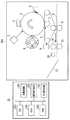
次に、図2を参照して、図1中の画像形成部300の構成例について詳細に説明する。図2は、本実施例に係る画像形成装置の構成を示す図である。 Next, a configuration example of the
図2に示すように、感光ドラム1の周囲には、帯電装置2と、露光装置3と、現像装置4と、中間転写ベルト5と、感光ドラムクリーナ6と、一次転写装置7とが配置されている。中間転写ベルト5の周囲には、二次転写装置8と、中間転写ベルトクリーナ9とが配置されている。二次転写装置8の後方には、定着ローラ10と、対向ローラ11と、正反射光測定装置12と、排紙トレイ13とが配置されている。 As shown in FIG. 2, a
感光ドラム1の表面は、帯電装置2によって所定の電位に均一に帯電される。露光装置3は、画像データを受けて露光光(例えばレーザ光)を放射する。放射された露光光は、ポリゴンミラーやfθレンズ(これらは、図2中には図示せず)を経て、図2中の矢印方向に回転している感光ドラム1上に露光走査される。これにより、感光ドラム1上には画像データに応じた静電潜像が形成される。この静電潜像は、現像装置4から供給されるトナーによって可視画像(トナー像)として現像される。本実施例における現像装置は、いわゆるロータリー型現像装置であり、ブラック(K),シアン(C),マゼンタ(M),イエロー(Y)の各色トナーに対応した色現像器4K,4Y,4C,4Mを備えている。カラー画像形成の際は、各色現像器が順に、感光ドラムに対向する現像位置に移動して現像を行う。なお、各色現像器を感光ドラム1の周面に並べて配置する方式や、色現像器ごとの感光ドラムを中間転写ベルトの周囲に並べて配置する、いわゆるタンデム型の現像方式を採用しても良い。また、現像装置は、一成分若しくは二成分の何れかの方式を用いた装置であっても良い。感光ドラム1上に現像されたトナー像は、複数のローラ間に加張されて無端駆動される中間転写ベルト5上に、一次転写装置7の作用によって転写される。感光ドラム1上に残留したトナーは、感光ドラムクリーナ6によって除去され、感光ドラム1上に残留した残留電位は、除電装置(図2中には図示せず)によって除去される。この動作を、現像装置4において使用される各色の現像器(4K,4Y,4C,4M)を移動して繰り返す。そして、中間転写ベルト5上に順次転写された複数の色のトナーからなるトナー像は、二次転写装置8により給紙トレイ(図2中には図示せず)から搬送されてきた記録媒体Pに転写される。中間転写ベルト5上に残留したトナーは、中間転写ベルトクリーナ9によって除去される。定着ローラ10及び対向ローラ11は、内蔵ヒータ(図2中には図示せず)を制御することにより、夫々温度を変えることができる。また、画像形成部300は、加圧手段(図2中には図示せず)により、定着ローラ10と、対向(加圧)ローラ11との間の圧力を変更できるように構成されている。二次転写装置8から搬送された未定着のトナー像が載った記録媒体Pは、定着ローラ10と、対向ローラ11との間を通過する際に熱及び圧力が与えられ、トナー画像が定着される。定着工程後に通過する搬送路近傍に設置された正反射光測定装置12は、光沢度測定実行の有無に応じて、形成されたトナー定着画像の正反射光強度を測定する。なお、正反射光測定装置12の設定場所である搬送路近傍とは、搬送されてくる記録媒体上のトナー画像の光沢度を測定できる程度の距離だけ搬送経路から離れた位置を指す。正反射光測定装置12の構成は後述する。トナー定着画像は、光沢度の測定後、排紙トレイ13より排出される。 The surface of the photosensitive drum 1 is uniformly charged to a predetermined potential by the charging
画像形成部300の各種構成要素は、中央演算処理装置(CPU)220と、制御プログラムを記憶しておくROM230と、入力データの記憶領域や作業用記憶領域を提供するRAM240とを備えるコントローラ20によって制御される。コントローラ20は、入力画像データに対して種々の処理を行うことで入力画像データをプリンタで出力するためのプリントデータに変換する画像処理部200と、正反射光測定装置12で測定された正反射光強度から光沢度を決定する光沢度決定部210とを備える。 The various components of the
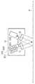
次に、図2中の正反射光測定装置12の構成例について詳細に説明する。図3は、図2中の正反射光測定装置12の構成を示す概略構成図である。図3に示すように、正反射光測定装置12は、発光手段1201と、レンズL1と、レンズL2と、受光手段1202とから構成される。測定面Pの法線に対し、入射角θと、受光角θ’とが等しくなるように、発光手段1201及び受光手段1202を設置し、発光手段1201から光を測定面Pに入射させ、正反射した光を受光手段1202にて測定することにより、光沢度は測定される。このような光沢度の測定方法は、JISZ8741に規定されている。発光手段1201から照射された光は、レンズL1を通して平行光にされ、この平行光が測定面Pに角度θで入射する。そして、正反射方向に反射した光は、レンズL2を通して集光され、この集光された光を受光手段1202によって測定する。 Next, a configuration example of the regular reflection
次に、本実施例に係る画像形成システムにおいて、階調画像の光沢度を取得するまでの動作の工程を説明する。図4は、光沢度の測定工程を説明するフローチャートである。プリンタドライバ(図1及び図2中には図示せず)において、ユーザが光沢度の測定を指定したときに光沢度の測定が実行される。 Next, in the image forming system according to the present embodiment, an operation process until the glossiness of the gradation image is acquired will be described. FIG. 4 is a flowchart for explaining the glossiness measurement process. In the printer driver (not shown in FIGS. 1 and 2), the glossiness measurement is executed when the user designates the glossiness measurement.
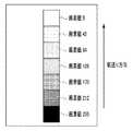
まず、パターン画像格納部207から光沢度を測定するためのパターン画像データが読み出される(ステップS1001)。図5に、パターン画像の一例を示す。図5に示すように、階調ごとの光沢度を順次測定できるように、階調の異なるパッチ画像が、紙送り方向に対して平行に並んで配置されている。また、このパターン画像は、複数の色のトナーのうちの、紙白部と、画像部とにおける拡散反射光の差が、紙白部と、画像部とにおける鏡面反射光の差に比べて十分小さい色のトナーで形成される。トナーの選択方法の詳細は後述する。 First, pattern image data for measuring the glossiness is read from the pattern image storage unit 207 (step S1001). FIG. 5 shows an example of a pattern image. As shown in FIG. 5, patch images having different gradations are arranged in parallel to the paper feed direction so that the glossiness for each gradation can be measured sequentially. In addition, in this pattern image, among the toners of a plurality of colors, the difference in diffuse reflection light between the paper white portion and the image portion is sufficiently larger than the difference in specular reflection light between the paper white portion and the image portion. Formed with small color toner. Details of the toner selection method will be described later.
読み出されたパターン画像データは、ハーフトーン処理部206によって、ハーフトーン処理され2値データに変換される(ステップS1002)。 The read pattern image data is halftone processed by the
ハーフトーン処理部206で2値化された画像データは画像形成部300に送られ、上記図2の説明で示した画像形成部300の構成を介して、露光、現像、転写、定着の各ステップを踏んでトナー画像の形成が行われる(ステップS1003)。 The image data binarized by the
次に、形成された各階調パッチ画像の正反射光強度を、正反射光測定装置12により測定する(ステップS1004)。 Next, the regular reflection light intensity of each formed gradation patch image is measured by the regular reflection light measurement device 12 (step S1004).
次に、光沢度決定部210は、ステップ1004で測定したトナー画像の正反射光強度から、各種トナーにおける光沢度を決定する(ステップS1005)。 Next, the
なお、本実施例においては、測定された正反射光強度を光沢度と決定するが、予め作成されたLUTや変換式を用いて変換した値を用いてもよい。また、変換LUTや変換式は、トナーによらず同一のものを用いてもよいし、トナーごとに異なるものを用いてもよい。 In the present embodiment, the measured specular reflection light intensity is determined as the glossiness, but a value converted using a previously created LUT or conversion equation may be used. Further, the same conversion LUT and conversion formula may be used regardless of the toner, or different ones may be used for each toner.
(深い入射角による光沢度測定の理由)
さて、本発明の画像形成装置における正反射光測定においては、測定面への光の入射角度を、より深い入射角とすることが望まれる。以下で、浅い入射角の場合の正反射光測定の例と、深い入射角の場合の正反射光測定の例とを示しながら、その理由を説明する。(Reasons for measuring glossiness due to deep incident angle)
In the specular reflection measurement in the image forming apparatus of the present invention, it is desired that the incident angle of light on the measurement surface is a deeper incident angle. Hereinafter, the reason will be described while showing an example of specular reflection light measurement in the case of a shallow incident angle and an example of specular reflection light measurement in the case of a deep incident angle.
まず、浅い入射角で正反射光を測定した例を示す。図6は、浅い入射角として入射角θを60度とした場合の正反射光測定装置12の構成を示す概略構成図である。発光手段1201及びレンズL1が測定面P1の法線に対し60度傾いて設置されており、それに対向するレンズL2及び受光手段1202が、測定面P1の法線に対し発光手段1201と反対方向に60度傾いて設置されている。 First, an example in which specular reflection light is measured at a shallow incident angle is shown. FIG. 6 is a schematic configuration diagram showing the configuration of the regular reflection
通常、発光手段1201から照射された光はレンズL1を通して平行光となり、正反射光測定装置12から既定の距離D離れた位置の測定面P1で反射され、正反射方向に反射した光Lum1がレンズL2を通して集光されて受光手段1202によって測定される。 Normally, the light emitted from the light emitting means 1201 becomes parallel light through the lens L1, and is reflected by the measurement surface P1 at a predetermined distance D away from the specular reflection
しかしながら、画像形成装置において用紙搬送中に、光測定装置と、測定面とを接触させることなく、光沢度の測定を行う場合には、紙の浮き若しくはうねり又は装置の振動等により、正反射光測定装置から測定面までの距離が変動してしまう。図6中の測定面P1は、正反射光測定装置12から既定の距離D離れた位置にある測定面である。図6中の測定面P2は、正反射光測定装置12から測定面までの距離が、既定の距離DからΔD変動した位置にある測定面である。 However, when the glossiness is measured without bringing the light measurement device into contact with the measurement surface during paper conveyance in the image forming apparatus, the specularly reflected light is caused by paper floating or waviness or vibration of the device. The distance from the measuring device to the measuring surface will fluctuate. A measurement surface P1 in FIG. 6 is a measurement surface located at a predetermined distance D from the regular reflection
浅い入射角で入射光が照射されると、測定面までの距離の変動がある場合には、図6中Lum2で示すように正反射方向に反射した反射光の中心と、受光手段1202の中心とのずれ幅が大きいため、受光手段1202で測定される受光量が安定しない。このずれ幅は、入射角が浅いほど大きく、入射角が深いほど小さくなる。 When incident light is irradiated at a shallow incident angle, if there is a variation in the distance to the measurement surface, the center of the reflected light reflected in the regular reflection direction and the center of the light receiving means 1202 as shown by Lum2 in FIG. The amount of received light measured by the light receiving means 1202 is not stable. This shift width is larger as the incident angle is shallower and is smaller as the incident angle is deeper.
次に、深い入射角で正反射光を測定した例を示す。図7は、深い入射角として入射角θを20度とした場合の正反射光測定装置12の構成を示す概略構成図である。発光手段1201及びレンズL1が測定面P1の法線に対し20度傾いて設置されており、それに対向するレンズL2及び受光手段1202が、測定面P1の法線に対し発光手段1201と反対方向に20度傾いて設置されている。図7中の測定面P1は、正反射光測定装置12から既定の距離D離れた位置にある測定面である。図7中の測定面P2は、正反射光測定装置12から測定面までの距離が、既定の距離DからΔD変動した位置にある測定面である。 Next, an example in which specularly reflected light is measured at a deep incident angle is shown. FIG. 7 is a schematic configuration diagram showing a configuration of the regular reflection
図7中のLum2に示すように、深い入射角で入射光が照射されると、測定面までの距離の変動ΔDがある場合でも、正反射方向に反射した反射光の中心と、受光手段1202の中心とのずれ幅は小さい。 As shown by Lum2 in FIG. 7, when incident light is irradiated at a deep incident angle, the center of the reflected light reflected in the regular reflection direction and the light receiving means 1202 even when there is a variation ΔD in the distance to the measurement surface. The deviation width from the center of is small.
従って、正反射光測定装置と、測定面との間の距離に変動がある場合には、入射角がより深くなるように正反射光測定装置を構成すれば、受光手段1202によって測定される光量の変動は少なくなり、正反射光測定を安定して行うことができる。 Accordingly, when the distance between the specular reflection light measurement device and the measurement surface varies, the amount of light measured by the light receiving means 1202 can be configured by configuring the specular reflection light measurement device so that the incident angle is deeper. The fluctuation of the is reduced, and regular reflection light measurement can be performed stably.
また、浅い入射角よりも深い入射角であるほうが、図6中及び図7中DWで示す正反射光測定装置12の幅を小さくすることができるため、装置を小型化できる。さらに、浅い入射角よりも深い入射角であるほうが、図中PWで示す入射光の照射領域も小さくすることができるため、必要となる測定パッチ画像サイズが抑えられ、測定に要するトナー及び用紙の節約になる。 Moreover, since the width | variety of the regular reflection
なお、図7においては入射角θを20度で配置した例を示しているが、入射角はこれに限られるものではなく、正反射光測定装置から測定面までの距離の変動がある場合に、受光手段1202で測定される受光量が安定する角度であれば良い。 Although FIG. 7 shows an example in which the incident angle θ is 20 degrees, the incident angle is not limited to this, and the distance from the specular reflection light measuring device to the measurement surface varies. The received light amount measured by the
(光沢度測定に適したトナー色を選択する方法)
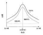
図8は、入射角θで測定面に光を照射させた場合の、受光角θ’を中心とした正反射方向の反射光強度分布を表すグラフである。図8に示すように、測定面で正反射方向に反射する正反射光は、拡散反射光と、鏡面反射光とを含む(本明細書では、正反射方向の拡散反射光と、鏡面反射光とを合わせた光を正反射光と記述している)。拡散反射光は、測定面内部に侵入し、吸収・散乱されて表面から放出される光である。鏡面反射光は、測定面に対して、入射角と同じ角度で反対方向に跳ね返る光である。(Method of selecting a toner color suitable for glossiness measurement)
FIG. 8 is a graph showing the reflected light intensity distribution in the regular reflection direction centered on the light receiving angle θ ′ when the measurement surface is irradiated with light at the incident angle θ. As shown in FIG. 8, the regular reflection light reflected in the regular reflection direction on the measurement surface includes diffuse reflection light and specular reflection light (in this specification, diffuse reflection light and specular reflection light in the regular reflection direction). Is described as regular reflection light). Diffuse reflected light is light that enters the measurement surface, is absorbed and scattered, and is emitted from the surface. Specular reflection light is light that rebounds in the opposite direction at the same angle as the incident angle with respect to the measurement surface.
光沢度は一般に、正反射光に含まれる鏡面反射光の強さによって決まり、鏡面反射光が強ければ光沢度は高いといえる。また、鏡面反射光の強さ(強度)は、測定面の表面凹凸に応じて異なり、一般的には、測定面の表面が平滑であるほど正反射方向の鏡面反射光強度は強く、反対に測定面の表面が荒れているほど正反射方向の鏡面反射光強度は弱くなる。 The glossiness is generally determined by the intensity of the specular reflection light included in the regular reflection light. If the specular reflection light is strong, the glossiness is high. In addition, the intensity (intensity) of specular reflected light varies depending on the surface irregularities of the measurement surface. In general, the smoother the surface of the measurement surface, the stronger the specular reflected light intensity in the specular reflection direction. The rougher the surface of the measurement surface, the weaker the specular reflection light intensity in the regular reflection direction.
光沢度を決定するためには鏡面反射光強度を測定することが望ましいが、正反射光から鏡面反射光のみを分離して強度を測定することは単純にはできない。そのため、通常は、鏡面反射光強度に対して拡散反射光強度が無視可能となる入射角で光を照射し、正反射光の強度から光沢度を算出している。紙の光沢度測定に関する通常の入射角として、JISZ8741に入射角75度の適用例が記載されている。また、電子写真記録方式(EP)のプリント物の光沢度測定であれば、入射角を60度とすることが一般的である。 In order to determine the gloss level, it is desirable to measure the intensity of the specular reflection light, but it is not simply possible to measure the intensity by separating only the specular reflection light from the regular reflection light. Therefore, normally, the light is irradiated at an incident angle at which the diffuse reflected light intensity is negligible with respect to the specular reflected light intensity, and the glossiness is calculated from the intensity of the regular reflected light. As a normal incident angle for measuring the glossiness of paper, JISZ8741 describes an application example with an incident angle of 75 degrees. In addition, when measuring the glossiness of electrophotographic recording (EP) printed matter, the incident angle is generally set to 60 degrees.
画像形成装置内(具体的には、正反射光測定装置12内)でより安定した正反射光測定を行うために、通常使用される角度よりも深い入射角で正反射光を測定した場合には、受光手段で測定される鏡面反射光が減少する。従って、拡散反射光が正反射光の主な成分となるため、見た目の光沢感と得られた光沢度が一致しない場合がある。 When specular reflection light is measured at an incident angle deeper than a normally used angle in order to perform more stable specular reflection measurement in the image forming apparatus (specifically, in the specular reflection measurement apparatus 12). The specular reflection light measured by the light receiving means decreases. Accordingly, since diffusely reflected light is the main component of specularly reflected light, the apparent glossiness may not match the glossiness obtained.
以下に、紙白部からベタ画像(トナーが密に被覆されている領域)までの階調画像の光沢度を測定した例を示す。階調画像として、普通紙にブラックトナーを用いてEP方式で作成した複数の階調パッチを持つ画像であり、紙白部が最も光沢感が低く、ベタ画像に近づくにつれて見た目の光沢感が高くなる画像を使用した。 The following shows an example in which the glossiness of a gradation image from a white paper portion to a solid image (a region where toner is densely covered) is measured. As a gradation image, it is an image having a plurality of gradation patches created by the EP method using black toner on plain paper. The white portion of the paper has the lowest glossiness, and the apparent glossiness increases as it approaches the solid image. I used the following image.
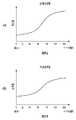
図9は、K単色階調パターン画像における60度光沢度及び20度光沢度の特性を表すグラフである。図9(a)に示す60度光沢度では、紙白で最も光沢度が低く、Kベタ画像(黒トナーが密に被覆されている領域)に近づくにつれて光沢度は高くなる。この傾向は見た目の光沢感とも一致する。一方、図9(b)に示す20度光沢度では、紙白からKベタ画像に近づくにつれて算出される光沢度は低くなっており、この傾向は見た目の光沢感とは一致しない。 FIG. 9 is a graph showing characteristics of 60 degree glossiness and 20 degree glossiness in a K single color gradation pattern image. With the 60 degree glossiness shown in FIG. 9A, the glossiness is the lowest in paper white, and the glossiness increases as it approaches a K solid image (a region where black toner is densely covered). This tendency is consistent with the apparent glossiness. On the other hand, in the 20 degree glossiness shown in FIG. 9B, the glossiness calculated as the white solid image approaches the K solid image is low, and this tendency does not match the apparent glossiness.
本発明は、上記の、算出される光沢度と、見た目の光沢度との不一致という課題を解決するために、紙白の拡散反射光と、ベタ画像の拡散反射光との差が少ない色材を用いて光沢度を取得することを特徴としている。 In order to solve the above-described problem of mismatch between the calculated glossiness and the apparent glossiness, the present invention provides a color material having a small difference between the diffuse reflected light of the paper white and the diffuse reflected light of the solid image. It is characterized in that the glossiness is acquired by using.
本実施例では、光源として、正反射光測定装置12における発光手段1201の分光放射輝度が、標準光源であるD65光源と、分光視感効率との掛け合わせに等価な光源(図10を参照)を用いている。 In the present embodiment, as the light source, a light source whose spectral radiance of the light emitting means 1201 in the specular reflected
また、図11に、紙白及びC,M,Y,K各トナーのベタ画像の分光反射率を示す。分光反射率とは、理想的な白色面に光を照射したときの各波長の反射率を1とし、測定面に光を照射したときに測定される各波長の光強度の割合である。図11中には、紙白に対する分光反射率301と、Cベタ画像に対する分光反射率302と、Mベタ画像に対する分光反射率303と、Yベタ画像に対する分光反射率304と、Kベタ画像に対する分光反射率305とが示されている。 FIG. 11 shows spectral reflectances of solid images of paper white and C, M, Y, and K toners. The spectral reflectance is the ratio of the light intensity of each wavelength measured when the reflectance of each wavelength when the ideal white surface is irradiated with light is 1, and the measurement surface is irradiated with light. In FIG. 11,
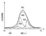
さらに、図12に、図10に示した分光放射輝度特性の発光手段を用いて、図11に示す分光反射率特性の紙白及びC,M,Y,K各トナーのベタ画像に照射した際の、拡散反射光の分光放射輝度を示す。図12中には、紙白に対する拡散反射光の分光放射輝度401並びにCベタ画像、Mベタ画像、Yベタ画像、及びKベタ画像に対する拡散反射光の分光放射輝度402〜405が示されている。ここで、分光放射輝度とは、単位面積、単位立体角当たりにおける、光の波長ごとのエネルギー量である。 Further, in FIG. 12, when the light emitting means having the spectral radiance characteristic shown in FIG. 10 is used to irradiate the solid white image of the white, C, M, Y, and K toners having the spectral reflectance characteristic shown in FIG. The spectral radiance of diffusely reflected light is shown. In FIG. 12, the
本実施例で用いた発光手段と、各トナーとの組み合わせにおいて、紙白の拡散反射光と、ベタ画像の拡散反射光との差が小さいトナーはイエロートナーである(図12中401、404)。ここで、拡散反射光の差は、分光放射輝度から求められるCIELab色度の差(CIELab色差)から判断される。なお、分光放射輝度の差の二乗平均平方根など、その他の指標を用いてもよい。 In the combination of the light emitting means used in this embodiment and each toner, the toner having a small difference between the diffuse reflected light of the paper white and the diffuse reflected light of the solid image is yellow toner (401 and 404 in FIG. 12). . Here, the difference in diffuse reflected light is determined from the CIELab chromaticity difference (CIELab color difference) obtained from the spectral radiance. Other indices such as the root mean square of the difference in spectral radiance may be used.
以下に、紙白からYベタ画像まで複数の階調画像の光沢度を測定した例を示す。図13は、普通紙上にイエロートナーを用いて作成したY単色階調パターン画像における60度光沢度及び20度光沢度の特性を表すグラフである。図13(a)に示す60度光沢度では、紙白で最も光沢度が低く、ベタ画像に近づくにつれて光沢度は高くなる。また、図13(b)に示す20度光沢度でも同様に、紙白で最も光沢度が低くベタ画像に近づくにつれて光沢度は高くなる。この傾向は見た目の光沢感とも一致していることから、深い入射角(20度)であっても各階調における光沢度の変化を測定可能であることがわかる。 An example in which the glossiness of a plurality of gradation images from paper white to a solid Y image is measured is shown below. FIG. 13 is a graph showing characteristics of 60 degree glossiness and 20 degree glossiness in a Y single color gradation pattern image created using yellow toner on plain paper. With the 60 degree glossiness shown in FIG. 13A, the glossiness is the lowest for paper white, and the glossiness increases as the solid image is approached. Similarly, the glossiness of 20 degrees shown in FIG. 13B is the lowest glossiness of paper white, and the glossiness increases as it approaches a solid image. Since this tendency is consistent with the apparent glossiness, it can be seen that the change in the glossiness at each gradation can be measured even at a deep incident angle (20 degrees).
本実施例では、光源として、標準光源であるD65光源と、分光視感効率との掛け合わせに等価な分光放射輝度特性を持つ光源を用い、紙白部の拡散反射光と、画像部の拡散反射光との差が小さい色材としてイエロートナーを用いた。しかし、光源と、色材との組み合わせはこの組み合わせに限られるものではない。光源と、色材との組み合わせは、紙白部と、画像部とにおける拡散反射光の変化が、紙白部と、画像部とにおける鏡面反射光の変化に比べて十分小さければ、任意の組み合わせを用いて構わない。例えば、青色光源とシアントナー、赤色光源とイエロートナー、赤色光源とマゼンタトナーなどの組み合わせでも良い。 In this embodiment, a D65 light source that is a standard light source and a light source having spectral radiance characteristics equivalent to the multiplication of spectral luminous efficiency are used as the light source. Yellow toner was used as a color material having a small difference from the reflected light. However, the combination of the light source and the color material is not limited to this combination. The combination of the light source and the color material can be any combination as long as the change in the diffuse reflection light in the paper white portion and the image portion is sufficiently smaller than the change in the specular reflection light in the paper white portion and the image portion. May be used. For example, a combination of a blue light source and cyan toner, a red light source and yellow toner, a red light source and magenta toner, or the like may be used.
また、単色画像の光沢度測定だけではなく、光源波長に対して、紙白部の拡散反射光と、画像部の拡散反射光との差が小さいトナーの組み合わせで形成した画像であれば、多色であっても光沢度を測定可能である。例えば、イエローとマゼンタを用いて作成した2次色の階調変化画像に対して、赤色光源を用いて正反射光を測定し、光沢度を決定することで、紙白から2次色ベタ画像までの階調ごとの光沢度の変化を測定可能である。 In addition to measuring the glossiness of a monochromatic image, if the image is formed by a combination of toners in which the difference between the diffuse reflected light of the white paper portion and the diffuse reflected light of the image portion is small with respect to the light source wavelength, there are many Glossiness can be measured even for colors. For example, for a secondary color gradation change image created using yellow and magenta, the specular reflection light is measured using a red light source, and the glossiness is determined, so that a secondary solid color image from paper white is obtained. It is possible to measure the change in glossiness for each gradation up to.
なお、本実施例では、光源として、少なくとも一つの色のトナーに関して、紙白部と、画像部とにおける拡散反射光の変化が、紙白部と、画像部とにおける鏡面反射光の変化に比べて十分小さくなるような波長の光を発する光源を用いる。 In this embodiment, as a light source, for at least one color toner, a change in diffuse reflection light in the paper white portion and the image portion is compared with a change in specular reflection light in the paper white portion and the image portion. A light source that emits light having a wavelength that is sufficiently small.
また、本実施例においては、ベタ画像部の分光放射輝度を用いて、紙白部の分光放射輝度と、トナー画像部の分光放射輝度との差が最小となるトナーを決定したが、トナー決定方法は、この方法に限定されるものではない。その他の階調画像で測定した分光放射輝度や、トナーの吸収・透過特性から算出した予測値から、紙白部と、画像部とにおける拡散反射光の変化が、紙白部と、画像部とにおける鏡面反射光の変化に比べて十分小さいトナーに決定してもよい。 Further, in this embodiment, the toner that minimizes the difference between the spectral radiance of the white paper portion and the spectral radiance of the toner image portion is determined using the spectral radiance of the solid image portion. The method is not limited to this method. From the predicted values calculated from the spectral radiance measured with other gradation images and the absorption / transmission characteristics of the toner, the change in diffuse reflected light between the white paper portion and the image portion is the white paper portion and the image portion. The toner may be determined to be sufficiently smaller than the change in the specular reflection light.
また、紙白部と、画像部とにおける拡散反射光の変化が、紙白部と、画像部とにおける鏡面反射光の変化に比べて十分小さくなる光源と、トナーとの組み合わせは変わらないため、光沢度測定ごとに選択を行う必要はない。従って、予め選択された光源と、トナーとの組み合わせを用いてよい。 In addition, since the combination of the light source and the toner in which the change in the diffuse reflection light in the paper white portion and the image portion is sufficiently smaller than the change in the specular reflection light in the paper white portion and the image portion does not change, There is no need to make a selection for each gloss measurement. Therefore, a combination of a preselected light source and toner may be used.
実施例1では、深い入射角で光沢度を測定する場合であっても、複数の色のトナーのうちの、紙白部と、画像部とにおける拡散反射光の差が、紙白部と、画像部とにおける鏡面反射光の差に比べて十分小さい色のトナーで形成した画像を測定する。これにより、光沢度を精度良く測定することができる。なお、測定データは、諧調ごとの画像の光沢度の変化を利用した各種技術に適用可能である。例えば、光沢度測定データに基づいて、パターン画像中の最大光沢度と、最小光沢度との差が所定値以下となるように、定着温度などの画像形成条件を設定することで、画像の階調にかかわらず光沢が均一で良好な印象を与えるカラー画像を得る技術に適用できる。 In Example 1, even when the glossiness is measured at a deep incident angle, the difference in diffuse reflected light between the paper white portion and the image portion of the toners of a plurality of colors is the paper white portion. An image formed with a toner having a sufficiently small color compared to the difference in specular reflection light from the image portion is measured. Thereby, the glossiness can be accurately measured. Note that the measurement data can be applied to various techniques using the change in the glossiness of the image for each gradation. For example, by setting the image forming conditions such as the fixing temperature so that the difference between the maximum glossiness in the pattern image and the minimum glossiness is a predetermined value or less based on the glossiness measurement data, The present invention can be applied to a technique for obtaining a color image that gives a good impression with a uniform gloss regardless of tone.
実施例1では、同階調の光沢度がトナーの色によらず同等である場合について説明した。同階調の光沢度がトナーの色によらず同等であるので、複数の色のトナーのうちの一部のトナー画像で測定した光沢度を、その他のトナー画像の光沢度として適用することができた。 In the first embodiment, the case where the glossiness of the same gradation is the same regardless of the color of the toner has been described. Since the gloss level of the same gradation is the same regardless of the color of the toner, the gloss level measured for a part of the toner images of a plurality of colors can be applied as the gloss level of the other toner images. did it.
しかしながら、例えば、トナーの色によって、階調ごとのトナーの載り量またはトナーの溶融度が異なる場合、同じ階調であっても表面凹凸の粗さが変わり光沢度が異なってくる場合がある。 However, for example, when the applied amount of toner or the melting degree of the toner differs depending on the toner color, the roughness of the surface unevenness may change and the glossiness may be different even at the same gradation.
そこで、本発明をより効果的に実施するために、各色のトナーごとに光沢度を測定する画像形成装置について、以下で説明する。 Accordingly, in order to more effectively implement the present invention, an image forming apparatus that measures glossiness for each color toner will be described below.
図14は、本実施例に係る画像形成装置の構成を示す図である。画像形成装置のコントローラ20は、測定波長制御部250を備えており、画像形成部300で作成したパターン画像のトナーの色に応じて、正反射光測定装置12の光源を制御する。 FIG. 14 is a diagram illustrating the configuration of the image forming apparatus according to the present embodiment. The
次に、図14中の正反射光測定装置12の構成例について詳細に説明する。図15は、図14中の正反射光測定装置12の構成を示す概略構成図である。レンズL1、レンズL2、受光手段1202は、それぞれ図3で示した構成と同じであるため、説明を省略する。発光手段1201は、波長の異なる複数の光源(赤色光源1211、緑色光源1212、及び青色光源1213)を有する。発光光源を制御することで、光沢度を測定する光の波長を変更することができる。 Next, a configuration example of the regular reflection
図16は、本実施例に係る光沢度の測定工程を説明するフローチャートである。 FIG. 16 is a flowchart for explaining the glossiness measurement process according to this embodiment.
まず、複数の色のトナーのうちの一つの色のトナーで形成されるパターン画像を読み出す(ステップ2001)。 First, a pattern image formed with one color toner among a plurality of color toners is read (step 2001).
ステップS2002からステップS2003の処理は、それぞれ上述したステップS1002からステップS1003の処理と同じであるため、説明を省略する。 Since the processing from step S2002 to step S2003 is the same as the processing from step S1002 to step S1003, respectively, description thereof will be omitted.
次に、測定波長制御部250は、ステップS2001で読み出されたパターン画像のトナーの色に応じて、正反射光測定装置12の発光手段1201の光源を変更する(ステップS2004)。このとき、光源は、紙白部と、画像部とにおける拡散反射光の変化が、紙白部と、画像部とにおける鏡面反射光の変化に比べて十分小さくなる光源に変更される。例えば、シアントナー画像の正反射光測定時には光源は青色光源に変更され、イエロートナー画像の正反射光測定時には光源は緑色光源に変更され、マゼンタトナー画像の正反射光測定時には赤色光源に光源は変更される。これにより、各種トナーにおいて拡散反射光の変化が減少し、光沢度を精度よく取得可能となる。なお、前述の光源色と、トナーとの組み合わせは一例であり、各トナーに対して紙白部と、画像部とにおける拡散反射光の差が小さい任意の光源を使用することができる。 Next, the measurement
次に、ステップS2004で変更された波長の正反射光を、正反射光測定装置12を用いて測定する(ステップS2005)。 Next, the specularly reflected light having the wavelength changed in step S2004 is measured using the specularly reflected light measuring device 12 (step S2005).
次に、全ての対象トナーのパターン画像について正反射光の測定が終了したか判定する(S2006)。全ての対象トナーのパターン画像について正反射光の測定が終了していない場合、ステップS2001からステップS2006までの動作を繰り返して他の色のトナーのパターン画像の正反射光測定を行う。 Next, it is determined whether or not the measurement of specular reflection light has been completed for all target toner pattern images (S2006). If the measurement of specular reflection light has not been completed for all target toner pattern images, the operation from step S2001 to step S2006 is repeated to measure the specular reflection light of the pattern images of other color toners.
全ての対象トナーのパターン画像について正反射光の測定が終了している場合、光沢度決定部210において、各色のトナーの階調ごとの光沢度を決定する(ステップS2007)。決定方法は実施例1と同様の方法で行う。なお、本実施例でいう対象トナーとは、紙白部と、画像部とにおける拡散反射光の変化が、紙白部と、画像部とにおける鏡面反射光の変化に比べて十分小さくなる光源を保持しているトナーである。この条件を満たす光源がないトナーの光沢度に関しては、実施例1と同様にその他の色のトナー画像の正反射光強度から決定する。 When the measurement of specular reflection light has been completed for all target toner pattern images, the
本実施例では、正反射光の測定波長を変更する手段として、発光手段の光源を変更する例を示したが、正反射光の測定波長を変更する手段は、これに限定されない。例えば、図3中の発光手段1201と受光手段1202との間の光路上に、紙白部と、画像部とにおける拡散反射光の差が、紙白部と、画像部とにおける鏡面反射光の差に比べて十分小さくなる波長の光を透過するカラーフィルタを設置しても良い。正反射光測定装置12が異なる波長の光を透過する複数のカラーフィルタを備えるようにすれば、測定する画像の色材の色に応じて、カラーフィルタを変更することで測定波長を変更することができる。 In the present embodiment, the example of changing the light source of the light emitting means is shown as means for changing the measurement wavelength of specular reflection light, but means for changing the measurement wavelength of specular reflection light is not limited to this. For example, on the optical path between the
なお、好適には、光源やカラーフィルタの変更によって変化する受光手段における受光光量の差は、同一の測定面の測定値からキャリブレーションされる。 Preferably, the difference in the amount of received light in the light receiving means that changes by changing the light source and the color filter is calibrated from the measured values on the same measurement surface.
実施例2では、発光手段の光源を変更することにより、紙白部と、画像部とにおける拡散反射光の変化が、紙白部と、画像部とにおける鏡面反射光の変化に比べて十分小さくなるような波長の正反射光強度を測定する方法を説明した。 In the second embodiment, by changing the light source of the light emitting unit, the change in diffuse reflection light in the paper white portion and the image portion is sufficiently smaller than the change in specular reflection light in the paper white portion and the image portion. A method for measuring the intensity of specular reflection light having such a wavelength has been described.
本実施例では、測定面で反射した正反射光を波長ごとに分光して正反射光の強度を測定し、紙白部と、画像部とにおける拡散反射光の差が、紙白部と、画像部とにおける鏡面反射光の差に比べて十分小さい波長の正反射光強度を用いて光沢度を決定する。本実施例における画像形成装置の構成は、実施例1と同じであるため説明を省略する。 In this example, specularly reflected light reflected on the measurement surface is divided for each wavelength to measure the intensity of the specularly reflected light, and the difference in diffusely reflected light between the white paper portion and the image portion is the white paper portion, The glossiness is determined by using the intensity of specular reflection light having a wavelength sufficiently smaller than the difference in specular reflection light from the image portion. Since the configuration of the image forming apparatus in the present embodiment is the same as that in the first embodiment, description thereof is omitted.
図17は、本実施例に係る正反射光測定装置12の構成を示す概略構成図である。図17に示すように、正反射光測定装置12は、発光手段1203と、レンズL1と、レンズL2と、分光手段1204と、受光手段1205とから構成される。 FIG. 17 is a schematic configuration diagram illustrating a configuration of the regular reflection
発光手段1203は、白色LEDやハロゲンランプのような可視光全域にわたる発光スペクトルを持った光源である。分光手段1204は、回折格子やプリズムなどの光を波長ごとに分光可能な分光器である。受光手段1205は、複数の受光部をもつラインセンサである。 The light emitting means 1203 is a light source having an emission spectrum over the entire visible light region such as a white LED or a halogen lamp. The spectroscopic means 1204 is a spectroscope that can split light such as a diffraction grating and a prism for each wavelength. The light receiving means 1205 is a line sensor having a plurality of light receiving portions.
発光手段1203の光源から照射された光は、レンズL1を通して平行光となり、測定面Pで反射され、正反射方向に反射した光がレンズL2を通して集光され、分光器1204により分光される。その後、分光された光は、波長ごとにラインセンサ1205の異なる受光部に入射する。ラインセンサ1205は、各受光部に入射した波長の異なる光の強度を測定する。 The light emitted from the light source of the light emitting means 1203 becomes parallel light through the lens L1, is reflected by the measurement surface P, and the light reflected in the regular reflection direction is condensed through the lens L2, and is dispersed by the
図18は、本実施例に係る光沢度の測定工程を説明するフローチャートである。 FIG. 18 is a flowchart illustrating the glossiness measurement process according to the present embodiment.
まず、複数の色のトナーのうちの一つの色のトナーで形成されるパターン画像を読み出す(ステップ3001)。 First, a pattern image formed with one color toner among a plurality of color toners is read (step 3001).
ステップS3002からステップS3003の処理は、それぞれ上述したステップS1002からステップS1003の処理と同じであるため、説明を省略する。 Since the processing from step S3002 to step S3003 is the same as the processing from step S1002 to step S1003, respectively, description thereof will be omitted.
次に、図17に示す正反射光測定装置12を用いて、ステップS3003で形成された各階調パッチ画像の正反射光強度を、正反射光を波長ごとに分光して測定する(ステップS3004)。 Next, using the specular reflection
次に、全ての対象トナーのパターン画像について正反射光の測定が終了したか判定する(S3005)。全ての対象トナーのパターン画像について正反射光の測定が終了していない場合、ステップS3001からステップS3005までの動作を繰り返して他の色のトナーのパターン画像の正反射光測定を行う。 Next, it is determined whether or not the measurement of regular reflection light has been completed for all target toner pattern images (S3005). If the measurement of specular reflection light has not been completed for all target toner pattern images, the operation from step S3001 to step S3005 is repeated to measure the specular reflection light of other color toner pattern images.
全ての対象トナーのパターン画像について正反射光の測定が全て終了している場合、光沢度決定部210において各色のトナーの階調ごとの光沢度を決定する(ステップS3006)。 When the measurement of specular reflection light has been completed for all the target toner pattern images, the
本実施例における光沢度決定部210では、形成した画像のトナーの色に応じて、光沢度の決定の際に利用する正反射光の波長が異なる。測定した波長のうちの、紙白部と、画像部とにおける拡散反射光の差が、紙白部と、画像部とにおける鏡面反射光の差に比べて十分小さい波長の正反射光を選択し、選択した正反射光強度を用いることで、拡散反射光の影響を受けずに光沢度を決定することができる。 In the
なお、本実施例でいう対象トナーとは、紙白部と、画像部とにおける拡散反射光の変化が、紙白部と、画像部とにおける鏡面反射光の変化に比べて十分小さくなる正反射光の波長が存在するトナーである。この条件を満たす波長がないトナーの光沢度に関しては、実施例1と同様にその他の色のトナー画像の正反射光強度から決定する。 The target toner referred to in this embodiment is a regular reflection in which the change in diffuse reflection light in the paper white portion and the image portion is sufficiently smaller than the change in specular reflection light in the paper white portion and the image portion. A toner having a wavelength of light. The glossiness of the toner having no wavelength satisfying this condition is determined from the specular reflection light intensities of toner images of other colors as in the first embodiment.
(実行タイミング)
本発明における光沢度の測定は、ユーザがアプリケーションから光沢度測定を指定したタイミングで実行される。この実行により、光沢度測定のためのパターン画像が形成され、正反射光測定装置12により用紙に応じた画像の光沢度が測定される。ただし、前述の光沢度の測定の実行タイミングは一例であり、給紙トレイに新たに用紙が設置されたタイミングや、時間経過、印刷枚数に応じたタイミングで、光沢度測定を実行するようにしてもよい。(Execution timing)
The glossiness measurement in the present invention is executed at the timing when the user designates the glossiness measurement from the application. By this execution, a pattern image for glossiness measurement is formed, and the regular reflection
(色材の種類)
本発明を実施するための画像形成装置には、実施例1から実施例2に記載したC、M、Y、Kトナー以外のトナー(色材あるいは記録剤)が搭載されていても良い。具体的には、前記のC,M,Y,Kトナーより相対的に明度の高い淡色トナーや、透明トナーが搭載されていても、本発明を実施することは可能である。(Type of color material)
In the image forming apparatus for carrying out the present invention, toners (coloring materials or recording agents) other than the C, M, Y, and K toners described in the first to second embodiments may be mounted. Specifically, the present invention can be implemented even when a light-colored toner or a transparent toner having a relatively higher brightness than the C, M, Y, and K toners described above is mounted.
[その他の実施例]
また、本発明の目的は、以下の処理を実行することによっても達成される。即ち、上述した実施例の機能を実現するソフトウェアのプログラムコードを記録した記憶媒体を、システム或いは装置に供給し、そのシステム或いは装置のコンピュータ(またはCPUやMPU等)が記憶媒体に格納されたプログラムコードを読み出す処理である。この場合、記憶媒体から読み出されたプログラムコード自体が前述した実施例の機能を実現することになり、そのプログラムコード及び該プログラムコードを記憶した記憶媒体は本発明を構成することになる。[Other Examples]
The object of the present invention can also be achieved by executing the following processing. That is, a storage medium that records a program code of software that implements the functions of the above-described embodiments is supplied to a system or apparatus, and a computer (or CPU, MPU, etc.) of the system or apparatus is stored in the storage medium. This is the process of reading the code. In this case, the program code itself read from the storage medium realizes the functions of the above-described embodiments, and the program code and the storage medium storing the program code constitute the present invention.
Claims (9)
Translated fromJapanese前記複数の色の色材のうちの一部の色の色材で形成した画像の正反射光を測定する正反射光測定手段と、
前記正反射光測定手段により測定した前記正反射光の強度に基づいて、光沢度を決定する光沢度決定手段と
を備えることを特徴とする画像形成装置。An image forming apparatus that forms an image using color materials of a plurality of colors,
Specularly reflected light measuring means for measuring specularly reflected light of an image formed of a color material of a part of the plurality of color materials;
An image forming apparatus comprising: a gloss level determining unit that determines a gloss level based on the intensity of the regular reflected light measured by the regular reflected light measuring unit.
前記測定波長制御手段は、前記形成した画像の色材の色に応じて、紙白部と、画像部とにおける拡散反射光の差が、紙白部と、画像部とにおける鏡面反射光の差に比べて十分小さい波長に測定波長を変更することを特徴とする請求項1又は2に記載の画像形成装置。The image forming apparatus further comprises measurement wavelength control means for changing the measurement wavelength of the specularly reflected light,
The measurement wavelength control unit is configured such that the difference in diffuse reflection light between the white paper portion and the image portion is different from the specular reflection light difference between the white paper portion and the image portion according to the color of the color material of the formed image. The image forming apparatus according to claim 1, wherein the measurement wavelength is changed to a wavelength sufficiently smaller than that of the image forming apparatus.
前記測定波長制御手段は、使用する光源を、前記形成した画像の色材の色に応じて、紙白部と、画像部とにおける拡散反射光の差が、紙白部と、画像部とにおける鏡面反射光の差に比べて十分小さい波長の光源に変更することを特徴とする請求項3に記載の画像形成装置。The specularly reflected light measuring means includes a plurality of light sources that incident light of different wavelengths on the formed image, and a light receiving means that receives specularly reflected light reflected by the formed image,
The measurement wavelength control means uses a light source to be used according to the color material color of the formed image, and the difference in diffuse reflected light between the paper white portion and the image portion is different between the paper white portion and the image portion. The image forming apparatus according to claim 3, wherein the light source has a wavelength that is sufficiently smaller than a difference in specular reflection light.
前記形成した画像の色材の色に応じて、紙白部と、画像部とにおける拡散反射光の差が、紙白部と、画像部とにおける鏡面反射光の差に比べて十分小さい波長の光を透過するカラーフィルタが、正反射光の光路上に設置されることを特徴とする請求項3に記載の画像形成装置。The specularly reflected light measuring means is a light emitting means for making light incident on the formed image, a plurality of color filters that transmit light of different wavelengths, and a light receiving device that receives the specularly reflected light reflected by the formed image. Means and
Depending on the color material color of the formed image, the difference in diffuse reflection light between the paper white portion and the image portion is sufficiently smaller than the difference in specular reflection light between the paper white portion and the image portion. The image forming apparatus according to claim 3, wherein a color filter that transmits light is disposed on an optical path of specularly reflected light.
前記光沢度決定手段は、前記形成した画像の色材の色に応じて、前記受光手段で受光した分光された正反射光の中から、紙白部と、画像部とにおける拡散反射光の差が、紙白部と、画像部とにおける鏡面反射光の差に比べて十分小さい波長の正反射光を用いることにより、光沢度を決定することを特徴とする請求項1又は2に記載の画像形成装置。The specularly reflected light measuring means is a light emitting means for making light incident on the formed image, a spectroscopic means for splitting the specularly reflected light reflected by the formed image for each wavelength, and spectrally separated by the spectroscopic means. A light receiving means for measuring the intensity of the specularly reflected light,
The glossiness determining means determines the difference in diffuse reflected light between the white paper portion and the image portion from the specularly reflected light received by the light receiving means according to the color material color of the formed image. 3. The image according to claim 1, wherein the glossiness is determined by using specular reflection light having a wavelength sufficiently smaller than a difference in specular reflection light between the white paper portion and the image portion. Forming equipment.
正反射光測定手段が、前記複数の色の色材のうちの一部の色の色材で形成した画像の正反射光を測定する正反射光測定ステップと、
光沢度決定手段が、前記正反射光測定ステップで測定した前記正反射光の強度に基づいて、光沢度を決定する光沢度決定ステップと
を備えることを特徴とする画像形成方法。An image forming method for forming an image using color materials of a plurality of colors,
Regular reflection light measurement means for measuring regular reflection light of an image formed with a color material of a part of the color materials of the plurality of colors;
An image forming method comprising: a gloss level determining unit including a gloss level determining step for determining a gloss level based on the intensity of the regular reflected light measured in the regular reflected light measuring step.
Priority Applications (2)
| Application Number | Priority Date | Filing Date | Title |
|---|---|---|---|
| JP2013079422AJP2014202938A (en) | 2013-04-05 | 2013-04-05 | Image forming apparatus and image forming method |
| US14/231,994US20140301745A1 (en) | 2013-04-05 | 2014-04-01 | Image forming apparatus, image forming method, and medium |
Applications Claiming Priority (1)
| Application Number | Priority Date | Filing Date | Title |
|---|---|---|---|
| JP2013079422AJP2014202938A (en) | 2013-04-05 | 2013-04-05 | Image forming apparatus and image forming method |
Publications (2)
| Publication Number | Publication Date |
|---|---|
| JP2014202938Atrue JP2014202938A (en) | 2014-10-27 |
| JP2014202938A5 JP2014202938A5 (en) | 2016-04-14 |
Family
ID=51654547
Family Applications (1)
| Application Number | Title | Priority Date | Filing Date |
|---|---|---|---|
| JP2013079422APendingJP2014202938A (en) | 2013-04-05 | 2013-04-05 | Image forming apparatus and image forming method |
Country Status (2)
| Country | Link |
|---|---|
| US (1) | US20140301745A1 (en) |
| JP (1) | JP2014202938A (en) |
Cited By (2)
| Publication number | Priority date | Publication date | Assignee | Title |
|---|---|---|---|---|
| JP2020008540A (en)* | 2018-07-03 | 2020-01-16 | 株式会社リコー | Inspection device, inspection method, and program |
| JP2021092433A (en)* | 2019-12-10 | 2021-06-17 | コニカミノルタ株式会社 | Image formation apparatus and glossiness measuring method |
Families Citing this family (3)
| Publication number | Priority date | Publication date | Assignee | Title |
|---|---|---|---|---|
| JP5867454B2 (en)* | 2013-06-19 | 2016-02-24 | コニカミノルタ株式会社 | Image forming apparatus |
| JP6976758B2 (en) | 2017-07-12 | 2021-12-08 | キヤノン株式会社 | Image processing equipment, image processing methods, and programs |
| CN114136243B (en)* | 2021-10-18 | 2024-08-02 | 广州国显科技有限公司 | Device applied to measuring flatness of display panel |
Citations (7)
| Publication number | Priority date | Publication date | Assignee | Title |
|---|---|---|---|---|
| JP2005321643A (en)* | 2004-05-10 | 2005-11-17 | Ricoh Co Ltd | Image forming system |
| JP2009068891A (en)* | 2007-09-11 | 2009-04-02 | Ricoh Co Ltd | Reflected light detection apparatus, image characteristic measurement apparatus, and image forming apparatus |
| JP2010204170A (en)* | 2009-02-27 | 2010-09-16 | Brother Ind Ltd | Image forming apparatus |
| JP2010217875A (en)* | 2009-02-20 | 2010-09-30 | Ricoh Co Ltd | Image forming apparatus |
| JP2011169706A (en)* | 2010-02-18 | 2011-09-01 | Ricoh Co Ltd | Gloss evaluation device and gloss evaluation method |
| JP2012198188A (en)* | 2011-03-09 | 2012-10-18 | Toshiba Corp | Photodetection device and paper sheet processing apparatus including photodetection device |
| JP2012247280A (en)* | 2011-05-27 | 2012-12-13 | Ricoh Co Ltd | Image inspection device and image forming apparatus |
Family Cites Families (3)
| Publication number | Priority date | Publication date | Assignee | Title |
|---|---|---|---|---|
| US5963333A (en)* | 1996-09-12 | 1999-10-05 | Color Savvy Systems Limited | Color sensor |
| US20070013978A1 (en)* | 2005-07-13 | 2007-01-18 | Sharp Kabushiki Kaisha | Color information measuring device, print object information measuring device, printing device and electrronic equipment |
| US7676169B2 (en)* | 2006-05-22 | 2010-03-09 | Lexmark International, Inc. | Multipath toner patch sensor for use in an image forming device |
- 2013
- 2013-04-05JPJP2013079422Apatent/JP2014202938A/enactivePending
- 2014
- 2014-04-01USUS14/231,994patent/US20140301745A1/ennot_activeAbandoned
Patent Citations (7)
| Publication number | Priority date | Publication date | Assignee | Title |
|---|---|---|---|---|
| JP2005321643A (en)* | 2004-05-10 | 2005-11-17 | Ricoh Co Ltd | Image forming system |
| JP2009068891A (en)* | 2007-09-11 | 2009-04-02 | Ricoh Co Ltd | Reflected light detection apparatus, image characteristic measurement apparatus, and image forming apparatus |
| JP2010217875A (en)* | 2009-02-20 | 2010-09-30 | Ricoh Co Ltd | Image forming apparatus |
| JP2010204170A (en)* | 2009-02-27 | 2010-09-16 | Brother Ind Ltd | Image forming apparatus |
| JP2011169706A (en)* | 2010-02-18 | 2011-09-01 | Ricoh Co Ltd | Gloss evaluation device and gloss evaluation method |
| JP2012198188A (en)* | 2011-03-09 | 2012-10-18 | Toshiba Corp | Photodetection device and paper sheet processing apparatus including photodetection device |
| JP2012247280A (en)* | 2011-05-27 | 2012-12-13 | Ricoh Co Ltd | Image inspection device and image forming apparatus |
Cited By (3)
| Publication number | Priority date | Publication date | Assignee | Title |
|---|---|---|---|---|
| JP2020008540A (en)* | 2018-07-03 | 2020-01-16 | 株式会社リコー | Inspection device, inspection method, and program |
| JP7172231B2 (en) | 2018-07-03 | 2022-11-16 | 株式会社リコー | Inspection device, inspection method, and program |
| JP2021092433A (en)* | 2019-12-10 | 2021-06-17 | コニカミノルタ株式会社 | Image formation apparatus and glossiness measuring method |
Also Published As
| Publication number | Publication date |
|---|---|
| US20140301745A1 (en) | 2014-10-09 |
Similar Documents
| Publication | Publication Date | Title |
|---|---|---|
| US8373899B2 (en) | Color image forming apparatus and color adjustment method | |
| JP5537194B2 (en) | Color image forming apparatus | |
| US7269369B2 (en) | Image forming apparatus with reduced paper consumption | |
| JP5006625B2 (en) | Image forming apparatus | |
| JP4645581B2 (en) | Image processing apparatus, image reading apparatus, and image forming apparatus | |
| US7773895B2 (en) | Image forming apparatus and control method of the same | |
| JP4804204B2 (en) | Recording material amount measuring method, image forming method, recording material amount measuring apparatus, and image forming apparatus | |
| JP2014202938A (en) | Image forming apparatus and image forming method | |
| US20110032553A1 (en) | Color material amount determination table forming method and color material amount measurement apparatus | |
| US20250047800A1 (en) | Information processing device and method of controlling image forming apparatus | |
| JP2005265752A (en) | Colorimetric device and image forming apparatus | |
| JP2003084532A (en) | Image forming apparatus color identification method and image forming apparatus | |
| JP4960932B2 (en) | Color reproduction range evaluation method, color reproduction range evaluation apparatus, and image forming apparatus | |
| JP2018004688A (en) | Image forming apparatus | |
| JP2004101358A (en) | Color-measuring device and image forming device using the same | |
| JP6669383B2 (en) | Measuring device, image forming device and image measuring device | |
| US11681252B2 (en) | Image forming apparatus | |
| US11953852B2 (en) | Image forming apparatus | |
| JP2007030302A (en) | Image forming apparatus, apparatus for forming color conversion parameter, test image forming method and program | |
| JP7686415B2 (en) | Image forming device | |
| JP2019105463A (en) | Spectrophotometer and image forming device | |
| JP2010169445A (en) | Method and instrument for measuring density of image, and image forming apparatus | |
| JP2005319675A (en) | Image forming apparatus and control method thereof | |
| JP2003084508A (en) | Image forming apparatus | |
| JP6827718B2 (en) | Image forming device |
Legal Events
| Date | Code | Title | Description |
|---|---|---|---|
| A521 | Request for written amendment filed | Free format text:JAPANESE INTERMEDIATE CODE: A523 Effective date:20160224 | |
| A621 | Written request for application examination | Free format text:JAPANESE INTERMEDIATE CODE: A621 Effective date:20160224 | |
| A977 | Report on retrieval | Free format text:JAPANESE INTERMEDIATE CODE: A971007 Effective date:20161116 | |
| A131 | Notification of reasons for refusal | Free format text:JAPANESE INTERMEDIATE CODE: A131 Effective date:20161122 | |
| A521 | Request for written amendment filed | Free format text:JAPANESE INTERMEDIATE CODE: A523 Effective date:20170119 | |
| A02 | Decision of refusal | Free format text:JAPANESE INTERMEDIATE CODE: A02 Effective date:20170307 |