JP2014184343A - Dual chamber and gear pump assembly for high pressure medicament delivery system - Google Patents
Dual chamber and gear pump assembly for high pressure medicament delivery systemDownload PDFInfo
- Publication number
- JP2014184343A JP2014184343AJP2014141687AJP2014141687AJP2014184343AJP 2014184343 AJP2014184343 AJP 2014184343AJP 2014141687 AJP2014141687 AJP 2014141687AJP 2014141687 AJP2014141687 AJP 2014141687AJP 2014184343 AJP2014184343 AJP 2014184343A
- Authority
- JP
- Japan
- Prior art keywords
- chamber
- high pressure
- delivery system
- delivering
- dose
- Prior art date
- Legal status (The legal status is an assumption and is not a legal conclusion. Google has not performed a legal analysis and makes no representation as to the accuracy of the status listed.)
- Granted
Links
Images


Classifications
- A—HUMAN NECESSITIES
- A61—MEDICAL OR VETERINARY SCIENCE; HYGIENE
- A61M—DEVICES FOR INTRODUCING MEDIA INTO, OR ONTO, THE BODY; DEVICES FOR TRANSDUCING BODY MEDIA OR FOR TAKING MEDIA FROM THE BODY; DEVICES FOR PRODUCING OR ENDING SLEEP OR STUPOR
- A61M5/00—Devices for bringing media into the body in a subcutaneous, intra-vascular or intramuscular way; Accessories therefor, e.g. filling or cleaning devices, arm-rests
- A61M5/14—Infusion devices, e.g. infusing by gravity; Blood infusion; Accessories therefor
- A61M5/142—Pressure infusion, e.g. using pumps
- A61M5/14212—Pumping with an aspiration and an expulsion action
- A61M5/14216—Reciprocating piston type
- A—HUMAN NECESSITIES
- A61—MEDICAL OR VETERINARY SCIENCE; HYGIENE
- A61M—DEVICES FOR INTRODUCING MEDIA INTO, OR ONTO, THE BODY; DEVICES FOR TRANSDUCING BODY MEDIA OR FOR TAKING MEDIA FROM THE BODY; DEVICES FOR PRODUCING OR ENDING SLEEP OR STUPOR
- A61M5/00—Devices for bringing media into the body in a subcutaneous, intra-vascular or intramuscular way; Accessories therefor, e.g. filling or cleaning devices, arm-rests
- A61M5/14—Infusion devices, e.g. infusing by gravity; Blood infusion; Accessories therefor
- A61M5/142—Pressure infusion, e.g. using pumps
- A61M5/14212—Pumping with an aspiration and an expulsion action
- A61M5/14236—Screw, impeller or centrifugal type pumps
- A—HUMAN NECESSITIES
- A61—MEDICAL OR VETERINARY SCIENCE; HYGIENE
- A61M—DEVICES FOR INTRODUCING MEDIA INTO, OR ONTO, THE BODY; DEVICES FOR TRANSDUCING BODY MEDIA OR FOR TAKING MEDIA FROM THE BODY; DEVICES FOR PRODUCING OR ENDING SLEEP OR STUPOR
- A61M5/00—Devices for bringing media into the body in a subcutaneous, intra-vascular or intramuscular way; Accessories therefor, e.g. filling or cleaning devices, arm-rests
- A61M5/14—Infusion devices, e.g. infusing by gravity; Blood infusion; Accessories therefor
- A61M5/142—Pressure infusion, e.g. using pumps
- A61M5/14212—Pumping with an aspiration and an expulsion action
- A61M5/1424—Manually operated pumps
- A—HUMAN NECESSITIES
- A61—MEDICAL OR VETERINARY SCIENCE; HYGIENE
- A61M—DEVICES FOR INTRODUCING MEDIA INTO, OR ONTO, THE BODY; DEVICES FOR TRANSDUCING BODY MEDIA OR FOR TAKING MEDIA FROM THE BODY; DEVICES FOR PRODUCING OR ENDING SLEEP OR STUPOR
- A61M5/00—Devices for bringing media into the body in a subcutaneous, intra-vascular or intramuscular way; Accessories therefor, e.g. filling or cleaning devices, arm-rests
- A61M5/14—Infusion devices, e.g. infusing by gravity; Blood infusion; Accessories therefor
- A61M5/142—Pressure infusion, e.g. using pumps
- A61M5/14244—Pressure infusion, e.g. using pumps adapted to be carried by the patient, e.g. portable on the body
- A—HUMAN NECESSITIES
- A61—MEDICAL OR VETERINARY SCIENCE; HYGIENE
- A61M—DEVICES FOR INTRODUCING MEDIA INTO, OR ONTO, THE BODY; DEVICES FOR TRANSDUCING BODY MEDIA OR FOR TAKING MEDIA FROM THE BODY; DEVICES FOR PRODUCING OR ENDING SLEEP OR STUPOR
- A61M5/00—Devices for bringing media into the body in a subcutaneous, intra-vascular or intramuscular way; Accessories therefor, e.g. filling or cleaning devices, arm-rests
- A61M5/14—Infusion devices, e.g. infusing by gravity; Blood infusion; Accessories therefor
- A61M5/142—Pressure infusion, e.g. using pumps
- A61M5/145—Pressure infusion, e.g. using pumps using pressurised reservoirs, e.g. pressurised by means of pistons
- A61M5/155—Pressure infusion, e.g. using pumps using pressurised reservoirs, e.g. pressurised by means of pistons pressurised by gas introduced into the reservoir
- F—MECHANICAL ENGINEERING; LIGHTING; HEATING; WEAPONS; BLASTING
- F04—POSITIVE - DISPLACEMENT MACHINES FOR LIQUIDS; PUMPS FOR LIQUIDS OR ELASTIC FLUIDS
- F04C—ROTARY-PISTON, OR OSCILLATING-PISTON, POSITIVE-DISPLACEMENT MACHINES FOR LIQUIDS; ROTARY-PISTON, OR OSCILLATING-PISTON, POSITIVE-DISPLACEMENT PUMPS
- F04C14/00—Control of, monitoring of, or safety arrangements for, machines, pumps or pumping installations
- F04C14/18—Control of, monitoring of, or safety arrangements for, machines, pumps or pumping installations characterised by varying the volume of the working chamber
- F04C14/20—Control of, monitoring of, or safety arrangements for, machines, pumps or pumping installations characterised by varying the volume of the working chamber by changing the form of the inner or outer contour of the working chamber
- F—MECHANICAL ENGINEERING; LIGHTING; HEATING; WEAPONS; BLASTING
- F04—POSITIVE - DISPLACEMENT MACHINES FOR LIQUIDS; PUMPS FOR LIQUIDS OR ELASTIC FLUIDS
- F04C—ROTARY-PISTON, OR OSCILLATING-PISTON, POSITIVE-DISPLACEMENT MACHINES FOR LIQUIDS; ROTARY-PISTON, OR OSCILLATING-PISTON, POSITIVE-DISPLACEMENT PUMPS
- F04C2/00—Rotary-piston machines or pumps
- F04C2/08—Rotary-piston machines or pumps of intermeshing-engagement type, i.e. with engagement of co-operating members similar to that of toothed gearing
- F04C2/082—Details specially related to intermeshing engagement type machines or pumps
- F04C2/084—Toothed wheels
- F—MECHANICAL ENGINEERING; LIGHTING; HEATING; WEAPONS; BLASTING
- F04—POSITIVE - DISPLACEMENT MACHINES FOR LIQUIDS; PUMPS FOR LIQUIDS OR ELASTIC FLUIDS
- F04C—ROTARY-PISTON, OR OSCILLATING-PISTON, POSITIVE-DISPLACEMENT MACHINES FOR LIQUIDS; ROTARY-PISTON, OR OSCILLATING-PISTON, POSITIVE-DISPLACEMENT PUMPS
- F04C2/00—Rotary-piston machines or pumps
- F04C2/08—Rotary-piston machines or pumps of intermeshing-engagement type, i.e. with engagement of co-operating members similar to that of toothed gearing
- F04C2/12—Rotary-piston machines or pumps of intermeshing-engagement type, i.e. with engagement of co-operating members similar to that of toothed gearing of other than internal-axis type
- F04C2/14—Rotary-piston machines or pumps of intermeshing-engagement type, i.e. with engagement of co-operating members similar to that of toothed gearing of other than internal-axis type with toothed rotary pistons
- A—HUMAN NECESSITIES
- A61—MEDICAL OR VETERINARY SCIENCE; HYGIENE
- A61M—DEVICES FOR INTRODUCING MEDIA INTO, OR ONTO, THE BODY; DEVICES FOR TRANSDUCING BODY MEDIA OR FOR TAKING MEDIA FROM THE BODY; DEVICES FOR PRODUCING OR ENDING SLEEP OR STUPOR
- A61M5/00—Devices for bringing media into the body in a subcutaneous, intra-vascular or intramuscular way; Accessories therefor, e.g. filling or cleaning devices, arm-rests
- A61M5/178—Syringes
- A61M5/31—Details
- A61M2005/3128—Incorporating one-way valves, e.g. pressure-relief or non-return valves
- A—HUMAN NECESSITIES
- A61—MEDICAL OR VETERINARY SCIENCE; HYGIENE
- A61M—DEVICES FOR INTRODUCING MEDIA INTO, OR ONTO, THE BODY; DEVICES FOR TRANSDUCING BODY MEDIA OR FOR TAKING MEDIA FROM THE BODY; DEVICES FOR PRODUCING OR ENDING SLEEP OR STUPOR
- A61M5/00—Devices for bringing media into the body in a subcutaneous, intra-vascular or intramuscular way; Accessories therefor, e.g. filling or cleaning devices, arm-rests
- A61M5/178—Syringes
- A61M5/31—Details
- A61M5/315—Pistons; Piston-rods; Guiding, blocking or restricting the movement of the rod or piston; Appliances on the rod for facilitating dosing ; Dosing mechanisms
- A61M5/31511—Piston or piston-rod constructions, e.g. connection of piston with piston-rod
- A61M2005/3152—Piston or piston-rod constructions, e.g. connection of piston with piston-rod including gearings to multiply or attenuate the piston displacing force
- A—HUMAN NECESSITIES
- A61—MEDICAL OR VETERINARY SCIENCE; HYGIENE
- A61M—DEVICES FOR INTRODUCING MEDIA INTO, OR ONTO, THE BODY; DEVICES FOR TRANSDUCING BODY MEDIA OR FOR TAKING MEDIA FROM THE BODY; DEVICES FOR PRODUCING OR ENDING SLEEP OR STUPOR
- A61M5/00—Devices for bringing media into the body in a subcutaneous, intra-vascular or intramuscular way; Accessories therefor, e.g. filling or cleaning devices, arm-rests
- A61M5/14—Infusion devices, e.g. infusing by gravity; Blood infusion; Accessories therefor
- A61M5/168—Means for controlling media flow to the body or for metering media to the body, e.g. drip meters, counters ; Monitoring media flow to the body
- A61M5/16804—Flow controllers
- A61M5/16809—Flow controllers by repeated filling and emptying of an intermediate volume
- A—HUMAN NECESSITIES
- A61—MEDICAL OR VETERINARY SCIENCE; HYGIENE
- A61M—DEVICES FOR INTRODUCING MEDIA INTO, OR ONTO, THE BODY; DEVICES FOR TRANSDUCING BODY MEDIA OR FOR TAKING MEDIA FROM THE BODY; DEVICES FOR PRODUCING OR ENDING SLEEP OR STUPOR
- A61M5/00—Devices for bringing media into the body in a subcutaneous, intra-vascular or intramuscular way; Accessories therefor, e.g. filling or cleaning devices, arm-rests
- A61M5/178—Syringes
- A61M5/20—Automatic syringes, e.g. with automatically actuated piston rod, with automatic needle injection, filling automatically
- A61M5/204—Automatic syringes, e.g. with automatically actuated piston rod, with automatic needle injection, filling automatically connected to external reservoirs for multiple refilling
- A—HUMAN NECESSITIES
- A61—MEDICAL OR VETERINARY SCIENCE; HYGIENE
- A61M—DEVICES FOR INTRODUCING MEDIA INTO, OR ONTO, THE BODY; DEVICES FOR TRANSDUCING BODY MEDIA OR FOR TAKING MEDIA FROM THE BODY; DEVICES FOR PRODUCING OR ENDING SLEEP OR STUPOR
- A61M5/00—Devices for bringing media into the body in a subcutaneous, intra-vascular or intramuscular way; Accessories therefor, e.g. filling or cleaning devices, arm-rests
- A61M5/178—Syringes
- A61M5/20—Automatic syringes, e.g. with automatically actuated piston rod, with automatic needle injection, filling automatically
- A61M5/2053—Media being expelled from injector by pressurised fluid or vacuum
- A—HUMAN NECESSITIES
- A61—MEDICAL OR VETERINARY SCIENCE; HYGIENE
- A61M—DEVICES FOR INTRODUCING MEDIA INTO, OR ONTO, THE BODY; DEVICES FOR TRANSDUCING BODY MEDIA OR FOR TAKING MEDIA FROM THE BODY; DEVICES FOR PRODUCING OR ENDING SLEEP OR STUPOR
- A61M5/00—Devices for bringing media into the body in a subcutaneous, intra-vascular or intramuscular way; Accessories therefor, e.g. filling or cleaning devices, arm-rests
- A61M5/178—Syringes
- A61M5/24—Ampoule syringes, i.e. syringes with needle for use in combination with replaceable ampoules or carpules, e.g. automatic
- A—HUMAN NECESSITIES
- A61—MEDICAL OR VETERINARY SCIENCE; HYGIENE
- A61M—DEVICES FOR INTRODUCING MEDIA INTO, OR ONTO, THE BODY; DEVICES FOR TRANSDUCING BODY MEDIA OR FOR TAKING MEDIA FROM THE BODY; DEVICES FOR PRODUCING OR ENDING SLEEP OR STUPOR
- A61M5/00—Devices for bringing media into the body in a subcutaneous, intra-vascular or intramuscular way; Accessories therefor, e.g. filling or cleaning devices, arm-rests
- A61M5/178—Syringes
- A61M5/31—Details
- A61M5/3146—Priming, e.g. purging, reducing backlash or clearance
- A—HUMAN NECESSITIES
- A61—MEDICAL OR VETERINARY SCIENCE; HYGIENE
- A61M—DEVICES FOR INTRODUCING MEDIA INTO, OR ONTO, THE BODY; DEVICES FOR TRANSDUCING BODY MEDIA OR FOR TAKING MEDIA FROM THE BODY; DEVICES FOR PRODUCING OR ENDING SLEEP OR STUPOR
- A61M5/00—Devices for bringing media into the body in a subcutaneous, intra-vascular or intramuscular way; Accessories therefor, e.g. filling or cleaning devices, arm-rests
- A61M5/178—Syringes
- A61M5/31—Details
- A61M5/315—Pistons; Piston-rods; Guiding, blocking or restricting the movement of the rod or piston; Appliances on the rod for facilitating dosing ; Dosing mechanisms
- A61M5/31533—Dosing mechanisms, i.e. setting a dose
- A61M5/31535—Means improving security or handling thereof, e.g. blocking means, means preventing insufficient dosing, means allowing correction of overset dose
- A—HUMAN NECESSITIES
- A61—MEDICAL OR VETERINARY SCIENCE; HYGIENE
- A61M—DEVICES FOR INTRODUCING MEDIA INTO, OR ONTO, THE BODY; DEVICES FOR TRANSDUCING BODY MEDIA OR FOR TAKING MEDIA FROM THE BODY; DEVICES FOR PRODUCING OR ENDING SLEEP OR STUPOR
- A61M5/00—Devices for bringing media into the body in a subcutaneous, intra-vascular or intramuscular way; Accessories therefor, e.g. filling or cleaning devices, arm-rests
- A61M5/178—Syringes
- A61M5/31—Details
- A61M5/315—Pistons; Piston-rods; Guiding, blocking or restricting the movement of the rod or piston; Appliances on the rod for facilitating dosing ; Dosing mechanisms
- A61M5/31565—Administration mechanisms, i.e. constructional features, modes of administering a dose
- A61M5/31576—Constructional features or modes of drive mechanisms for piston rods
- A61M5/31583—Constructional features or modes of drive mechanisms for piston rods based on rotational translation, i.e. movement of piston rod is caused by relative rotation between the user activated actuator and the piston rod
- A61M5/31585—Constructional features or modes of drive mechanisms for piston rods based on rotational translation, i.e. movement of piston rod is caused by relative rotation between the user activated actuator and the piston rod performed by axially moving actuator, e.g. an injection button
- A—HUMAN NECESSITIES
- A61—MEDICAL OR VETERINARY SCIENCE; HYGIENE
- A61M—DEVICES FOR INTRODUCING MEDIA INTO, OR ONTO, THE BODY; DEVICES FOR TRANSDUCING BODY MEDIA OR FOR TAKING MEDIA FROM THE BODY; DEVICES FOR PRODUCING OR ENDING SLEEP OR STUPOR
- A61M5/00—Devices for bringing media into the body in a subcutaneous, intra-vascular or intramuscular way; Accessories therefor, e.g. filling or cleaning devices, arm-rests
- A61M5/48—Devices for bringing media into the body in a subcutaneous, intra-vascular or intramuscular way; Accessories therefor, e.g. filling or cleaning devices, arm-rests having means for varying, regulating, indicating or limiting injection pressure
- A61M5/482—Varying injection pressure, e.g. by varying speed of injection
- A—HUMAN NECESSITIES
- A61—MEDICAL OR VETERINARY SCIENCE; HYGIENE
- A61M—DEVICES FOR INTRODUCING MEDIA INTO, OR ONTO, THE BODY; DEVICES FOR TRANSDUCING BODY MEDIA OR FOR TAKING MEDIA FROM THE BODY; DEVICES FOR PRODUCING OR ENDING SLEEP OR STUPOR
- A61M5/00—Devices for bringing media into the body in a subcutaneous, intra-vascular or intramuscular way; Accessories therefor, e.g. filling or cleaning devices, arm-rests
- A61M5/48—Devices for bringing media into the body in a subcutaneous, intra-vascular or intramuscular way; Accessories therefor, e.g. filling or cleaning devices, arm-rests having means for varying, regulating, indicating or limiting injection pressure
- A61M5/484—Regulating injection pressure
- F—MECHANICAL ENGINEERING; LIGHTING; HEATING; WEAPONS; BLASTING
- F04—POSITIVE - DISPLACEMENT MACHINES FOR LIQUIDS; PUMPS FOR LIQUIDS OR ELASTIC FLUIDS
- F04C—ROTARY-PISTON, OR OSCILLATING-PISTON, POSITIVE-DISPLACEMENT MACHINES FOR LIQUIDS; ROTARY-PISTON, OR OSCILLATING-PISTON, POSITIVE-DISPLACEMENT PUMPS
- F04C2220/00—Application
- F04C2220/24—Application for metering throughflow
Landscapes
- Health & Medical Sciences (AREA)
- Engineering & Computer Science (AREA)
- Hematology (AREA)
- Life Sciences & Earth Sciences (AREA)
- Vascular Medicine (AREA)
- Anesthesiology (AREA)
- Biomedical Technology (AREA)
- Heart & Thoracic Surgery (AREA)
- Veterinary Medicine (AREA)
- Public Health (AREA)
- Animal Behavior & Ethology (AREA)
- General Health & Medical Sciences (AREA)
- General Engineering & Computer Science (AREA)
- Mechanical Engineering (AREA)
- Infusion, Injection, And Reservoir Apparatuses (AREA)
- Rotary Pumps (AREA)
Abstract
Translated fromJapaneseDescription
Translated fromJapanese本出願は、2008年7月18日に出願された、米国仮出願第61/082,053号の、合衆国法典第35巻(35U.S.C.)第119条(e)に基づく優先権を主張し、その全ての開示は、参照としてここに組み込まれる。 This application is based on US Provisional Application No. 61 / 082,053, filed July 18, 2008, under 35 USC 35 (35USC) 119 (e). The entire disclosure of which is incorporated herein by reference.
本発明は、薬剤を送達するための高圧送達システムに関する。さらに詳しくは、本発明は、薬剤の漏れおよび不正確な用量を防止するために、薬剤の貯蔵チャンバから高圧を逸らす、高圧薬物送達システムに関する。 The present invention relates to a high pressure delivery system for delivering a drug. More particularly, the present invention relates to a high pressure drug delivery system that deflects high pressure from a drug storage chamber to prevent drug leakage and inaccurate doses.
ある状況下においては、ヒト組織に直接薬剤を注射することが望まれる。典型的には、シリンジが、筋肉組織層、皮下組織層および皮内組織層のような組織領域に、薬剤を注射するために使用される。これらの組織層の各々は、目標とされる組織層に流体を注射するために必要とされる流体圧力の量に影響する特定の性質を有している。これらの組織層の各々に流体を注射するとき、使用者は、特定の組織層と関連する異なる量の背圧に打ち勝つために、注射器具に十分な力を及ぼさなければならない。一般的に、医師および糖尿病患者のような自己注射者は、皮下層に流体を注射するために必要な力を熟知している。皮下および筋肉組織層への注射は、組織の特徴、ニードルの長さおよびニードルの直径またはゲージのために、患者または自己注射者に不快感をもたらす。皮内組織層への送達を達成するために、より短い、より小さいゲージのニードルを採用することが望まれる。 Under certain circumstances, it may be desirable to inject the drug directly into human tissue. Typically, syringes are used to inject drugs into tissue regions such as muscle tissue layers, subcutaneous tissue layers and intradermal tissue layers. Each of these tissue layers has certain properties that affect the amount of fluid pressure required to inject fluid into the targeted tissue layer. When injecting fluid into each of these tissue layers, the user must exert sufficient force on the injection device to overcome the different amounts of back pressure associated with a particular tissue layer. In general, self-injectors, such as doctors and diabetics, are familiar with the force required to inject fluid into the subcutaneous layer. Injections into the subcutaneous and muscular tissue layers cause discomfort to the patient or self-injector due to tissue characteristics, needle length and needle diameter or gauge. In order to achieve delivery to the intradermal tissue layer, it is desirable to employ shorter, smaller gauge needles.
ニードルの長さが短くなり、ニードルの直径が小さくなると、注射器具の流体力学が変わることが留意される。加えて、注射器具と目標とされる組織層との間の流体力学も、より短いニードルの長さが、皮内層のような異なる組織層へ流体を注射するために、また、変わる。筋肉、皮下および皮内組織層の組織密度が変わるので、流体が各々のタイプの組織層へ注射される容易さも変わる。組織密度の変化は、注射されたとき、流体に対して組織によって及ぼされる背圧に変化を引き起こす。例えば、皮内組織層と関連する背圧は、皮下組織層と関連する背圧よりも大きく、それにより、注射を成し遂げるために、より高圧と大きな力を必要とする。 It is noted that the fluid dynamics of the injection device changes as the needle length decreases and the needle diameter decreases. In addition, the hydrodynamics between the injection device and the targeted tissue layer will also change because shorter needle lengths inject fluid into different tissue layers, such as the intradermal layer. As the tissue density of the muscle, subcutaneous and intradermal tissue layers changes, the ease with which fluid is injected into each type of tissue layer also changes. The change in tissue density causes a change in the back pressure exerted by the tissue on the fluid when injected. For example, the back pressure associated with the intradermal tissue layer is greater than the back pressure associated with the subcutaneous tissue layer, thereby requiring higher pressure and greater force to achieve the injection.
現在、いくつかのペン型注射システムが、薬剤の皮下物質送達のために商業的に利用可能である。これらのペン型注射システムは、典型的には、5mmから12.7mmの間の長さを有する、29〜31ゲージのニードルを使用し、インシュリンのような、薬剤カートリッジの内容物を、患者の皮下組織層へ、すばやく、かつ、便利に、送達するために用いられる。薬剤カートリッジは、一般的に、標準の容積と大きさ(固定された断面積を含む)である。送達圧力は、使用者によって及ぼされる作動力とカートリッジの断面積の商である。カートリッジの断面積は固定されているので、高い送達圧力は、使用者による高い作動力を必要とする。 Currently, several pen injection systems are commercially available for subcutaneous substance delivery of drugs. These pen injection systems typically use a 29-31 gauge needle having a length between 5 mm and 12.7 mm, and the contents of the drug cartridge, such as insulin, Used to deliver quickly and conveniently to the subcutaneous tissue layer. Drug cartridges are typically of standard volume and size (including a fixed cross-sectional area). Delivery pressure is the quotient of the actuation force exerted by the user and the cross-sectional area of the cartridge. Since the cross-sectional area of the cartridge is fixed, a high delivery pressure requires a high actuation force by the user.
「極微針」ペン型システムが、皮下物質送達を容易にするために発展させられてきた。そのような「極微針」薬剤送達システムは、30〜34ゲージの範囲またはより細い、より小さい直径を有する、典型的には、3mm以下の、より短いニードルを含む。そのようなニードルの長さおよびゲージサイズの組合せは、深い皮内または浅い皮下組織層のような、ある選択された組織のみに、より正確に、目的物質を送達することができる、鋭く、さらに短い、先端形状を提供することが望ましく、それによって、制御された流体送達を可能にする。皮下送達のために用いられる、流通する典型的なペン型システムは、とりわけ、極微針を用いる皮膚の皮内層への流体注射と関連する高い背圧ゆえに、皮内層への送達のための自己注射者の一般集団による使用にとって、最適とは信じられていない。 “Microneedle” pen-type systems have been developed to facilitate subcutaneous substance delivery. Such “microneedle” drug delivery systems include shorter needles having a smaller diameter in the range of 30-34 gauge or thinner, typically 3 mm or less. Such needle length and gauge size combinations are sharp, further capable of delivering the target substance more accurately only to certain selected tissues, such as deep intradermal or shallow subcutaneous tissue layers. It is desirable to provide a short, tip shape, thereby allowing controlled fluid delivery. A typical pen-type system that is used for subcutaneous delivery is self-injecting for delivery to the intradermal layer, especially because of the high back pressure associated with fluid injection into the intradermal layer of the skin using microneedles. It is not believed to be optimal for use by the general population.
より高い背圧の観点から目標とされる組織層への効果的な薬剤送達を実現するために、ふたつの要因、注射の深さ精度および注射速度、を制御することが望まれる。このことは、背圧が相対的に高いため、皮内注射と関連して、特に、興味のあることであるが、同様な分析は、筋肉または皮下組織層へ注射するときに適用され得る。皮内組織層の狭い深さ範囲への薬剤の送達は、最初に確実になされ、注射の間維持されねばならない。深さ精度が得られると、他の組織層への薬剤の漏れ、または、皮膚を通した逆流を、最小化または除去するために、注射の速度が制御されねばならない。皮内薬剤送達および極微針の追加の詳細は、全てが、ベクトン・ディキンソン・アンド・カンパニーに帰す、2002年12月17日に発行された特許文献1、2003年5月27日に発行された特許文献2、2005年3月24日に発行された特許文献3および2005年3月24日に発行された特許文献4に、すでに、記載されており、その特許および出願の各々の全ての内容は、ここに参照として組み込まれる。 In order to achieve effective drug delivery to the targeted tissue layer in terms of higher back pressure, it is desirable to control two factors, injection depth accuracy and injection speed. This is particularly interesting in connection with intradermal injection because of the relatively high back pressure, but similar analysis can be applied when injecting into muscle or subcutaneous tissue layers. Delivery of the drug to a narrow depth range of the intradermal tissue layer must first be ensured and maintained during injection. Once depth accuracy is achieved, the rate of injection must be controlled to minimize or eliminate drug leakage into other tissue layers or backflow through the skin. Additional details of intradermal drug delivery and microneedles, all issued to Becton Dickinson & Company, US Pat.
皮膚の皮内組織層は、皮下組織領域よりもかなり密度が高い。特定の患者での皮内組織層の密度は、ある程度、患者の年齢、および、患者の体での注射部位の場所によって影響される、コラーゲンの構造の関数である。皮内組織層の増大した密度は、皮下組織領域へ注射するときに引き起こされる抵抗よりも、注射器具でのより大きい背圧抵抗を引き起こし得る。通常の薬剤送達ペンで皮内組織層に注射するときの増大された抵抗に打ち勝つために、使用者または患者は、注射器具のアクチュエータに、より大きな作動力(かなりのものであり得る。)を及ぼすか、ある種の動力注射器具を採用する必要がある。これらの適用において、注射器具は、使用者または患者によって及ぼされる付加的な力と同様に、皮内注射部位からのより大きな背圧に耐えるように設計されねばならない。さらに、注射器具を作動させるために必要とされる増大した作動力は、増大した流体圧力により所望の組織深さを超えて流体「ジェッティング」を引き起こす。 The intradermal tissue layer of the skin is much denser than the subcutaneous tissue region. The density of the intradermal tissue layer in a particular patient is a function of the structure of the collagen, which is influenced in part by the patient's age and the location of the injection site in the patient's body. The increased density of the intradermal tissue layer can cause greater back pressure resistance at the injection device than that caused when injecting into the subcutaneous tissue region. In order to overcome the increased resistance when injecting into the intradermal tissue layer with a normal drug delivery pen, the user or patient has a greater actuation force (which can be substantial) on the actuator of the injection device. It is necessary to employ some sort of powered injection device. In these applications, the injection device must be designed to withstand greater back pressure from the intradermal injection site as well as the additional force exerted by the user or patient. Furthermore, the increased actuation force required to actuate the injection device causes fluid “jetting” beyond the desired tissue depth due to increased fluid pressure.
通常の薬剤送達ペンは、注射が完了した後、およそ10秒間を越える時間、引き抜きでニードル先端からの「垂れ」を最小限にするため、ペン機構(送りネジ)とカートリッジの後端ストッパの「軸方向コンプライアンス」が釣り合い得るよう、使用者が、皮膚に置かれたニードルを保持することを要求する。そのような時間は、より高い背圧から生じるどんな付加的な軸方向コンプライアンスをも付随して起こるように、増大される必要があり、そのような増大された時間は、注射をなすために要求される力を減少させる。 Conventional drug delivery pens are pulled out for more than approximately 10 seconds after the injection is completed, so that the pen mechanism (feed screw) and cartridge back end stopper “ The user is required to hold the needle placed on the skin so that "axial compliance" can be balanced. Such time needs to be increased to accompany any additional axial compliance resulting from higher back pressure, and such increased time is required to make an injection. Reduce the power that is done.
薬剤の送達を理解することにおける進歩が進展すると、皮内送達システムの使用が増大することが期待される。薬剤物質を皮内に送達するための「標準の」長さのニードルは、上述したとおり、欠点を有する。多目的バイアル瓶からの薬剤物質でシリンジを吸引するために、皮内注射に適切なニードル長さを有する送達器具を用いることは不可能である。したがって、従来技術には、「標準の」長さのニードルおよび多目的バイアル瓶を用いる皮内注射を施すことを妨げる欠点が存在する。複数用量バイアル瓶に貯蔵された物質にアクセスすることが可能であり、上述した欠点に直面することなく皮膚の皮下領域にそのような物質を送達することができる薬剤送達器具を有することは有利である。 As progress in understanding drug delivery progresses, the use of intradermal delivery systems is expected to increase. “Standard” length needles for delivering drug substance intradermally have drawbacks as described above. In order to aspirate a syringe with drug substance from a multipurpose vial, it is not possible to use a delivery device having a needle length suitable for intradermal injection. Thus, the prior art has the disadvantage of hindering intradermal injection using “standard” length needles and multipurpose vials. It would be advantageous to have a drug delivery device that is capable of accessing substances stored in a multi-dose vial and that can deliver such substances to the subcutaneous region of the skin without facing the disadvantages described above. is there.
既存の薬剤送達ペンは、皮下にインシュリンを送達するためのシリンジをベースとするシステムを超えるいくつかの利点を提供する。再利用可能な薬剤送達ペンは、再充填される薬剤カートリッジを要求することなく、20またはそれ以上の用量を保持する。用量の設定は、ダイアルの使用で簡単に達成される。しかしながら、そのような薬剤送達ペンは、低圧の皮下注射のために設計される。インシュリンおよび他の薬剤の皮内注射は、薬剤のより速い摂取を提供し、それにより改善された治療に導く。既存の薬剤送達ペンは、皮内薬剤送達に関して幾つかの制限を有する。第一に、ペンにより提供される機械的な利点は最小限であり、使用者が、十分な圧力を発生するために、9.1kg(20lbs)以上の力を供給することを要求する。第二に、ペンの構成要素は、この高い力によって、しばしば損傷を受け、高圧での漏れおよび不正確さを招く。さらに、皮内薬剤送達と関係する高圧を得るために要求される薬剤送達ペンの大きさは、便利に運搬するためには使用者にとって余りにも大きすぎる。 Existing drug delivery pens offer several advantages over syringe-based systems for delivering insulin subcutaneously. A reusable drug delivery pen holds 20 or more doses without requiring a drug cartridge to be refilled. Dose setting is easily accomplished with the use of a dial. However, such drug delivery pens are designed for low pressure subcutaneous injection. Intradermal injection of insulin and other drugs provides faster uptake of the drug, thereby leading to improved therapy. Existing drug delivery pens have some limitations with respect to intradermal drug delivery. First, the mechanical benefits provided by the pen are minimal and require the user to supply a force of 9.1 kg (20 lbs) or more in order to generate sufficient pressure. Second, pen components are often damaged by this high force, leading to high pressure leakage and inaccuracies. Furthermore, the size of the drug delivery pen required to obtain the high pressure associated with intradermal drug delivery is too large for the user to carry conveniently.
ペン様で、用量ダイアル式の正確性とシリンジ様(小さい直径)の高圧能力を備えた使い易さの利点を有する、既存の皮内用ペン様器具は存在しない。既存の薬剤送達ペンは、皮内層に薬剤を注射するために大きな力を要求し、それによって、皮内薬剤注射を困難にする。さらに、薬剤送達ペンの構成部品は、高圧のために、しばしば、損傷され、それによって、薬剤の漏れと用量の不正確さを引き起こす。 There are no existing intradermal pen-like devices that are pen-like and have the advantages of ease of use with dose-dial accuracy and syringe-like (small diameter) high pressure capability. Existing drug delivery pens require great force to inject drugs into the intradermal layer, thereby making intradermal drug injection difficult. In addition, drug delivery pen components are often damaged due to high pressure, thereby causing drug leakage and dose inaccuracy.
それゆえに、使用者または患者が、治療薬、ワクチンおよび診断材料のような、化合物の高圧送達を、過度に大きな力の発揮を要求されることなく、または、扱いにくい器具をもたらすことなく、制御された速度で実現することを可能にする、システムおよび方法を提供する必要性が存在する。 Therefore, the user or patient can control high-pressure delivery of compounds, such as therapeutics, vaccines and diagnostic materials, without requiring excessive force exertion or resulting in cumbersome devices. There is a need to provide a system and method that allows it to be realized at a reduced speed.
本発明の態様によれば、薬剤送達と関連する高圧から用量設定機構を分離し、その結果、高圧により生ずる圧力が用量セッティングに作用しない、高圧薬剤送達システムが提供される。 In accordance with aspects of the present invention, a high pressure drug delivery system is provided that separates the dose setting mechanism from the high pressure associated with drug delivery so that the pressure caused by the high pressure does not affect the dose setting.
皮内領域のように、高圧適用において薬剤を送達するために、ペンのネジ式用量セッティングの正確さが、小さい内径のシリンジの水力学的な利点と結合している。カートリッジとシリンジとの間の弁作動は、用量設定の間はシリンジへの流れを可能にし、注射中は微細針と通す流れのみを可能にする、二つの逆止弁を備えた、プランジャ型の往復動器具のように機能する。逆止弁は、使用者が、シリンジに意図せずに過剰用量を注入したとき、使用者が、シリンジからカートリッジに用量を戻すことを可能にする。 Like the intradermal region, the accuracy of the pen screw dose setting is combined with the hydraulic advantage of a small inner diameter syringe for delivering medication in high pressure applications. The valve actuation between the cartridge and the syringe is a plunger type with two check valves that allows flow to the syringe during dose setting and only allows flow through the fine needle during injection. Functions like a reciprocating instrument. The check valve allows the user to return the dose from the syringe to the cartridge when the user unintentionally injects an overdose into the syringe.
本発明の他の態様によれば、使用者が、高圧薬剤送達を実現するために、ギアポンプアセンブリを用いる、高圧薬剤送達システムが提供される。 According to another aspect of the invention, a high pressure drug delivery system is provided in which a user uses a gear pump assembly to achieve high pressure drug delivery.
本発明の他の目的、利点および顕著な態様は、添付された図面と併せて解釈され、本発明の例示的な具体例を開示する、以下の詳細な説明から明らかになるだろう。 Other objects, advantages and salient aspects of the present invention will become apparent from the following detailed description, taken in conjunction with the accompanying drawings, which disclose exemplary embodiments of the invention.
本発明の種々の具体例の上述の利点および他の利点は、本発明の例示的な具体例の以下の詳細な説明および添付する図面からより明らかになるであろう。 The above and other advantages of various embodiments of the present invention will become more apparent from the following detailed description of exemplary embodiments of the present invention and the accompanying drawings.
各図を通して、同じ参照番号は、同じ部分、構成要素および構造に言及していることが理解されるだろう。 It will be understood that throughout the figures, the same reference numerals refer to the same parts, components and structures.
本発明の例示的な具体例は、好ましくは、典型的な3mlのカートリッジであって、小さな直径のシリンジから発生される高圧に適合する、好ましくは、使い捨てのシリンジに結合されたカートリッジを有する、高圧薬剤送達システムを含む。カートリッジおよびシリンジは、薬剤をカートリッジからシリンジに流すことを可能にし、その上、薬剤の送達の間の逆流を防止するバルブシステムによって結合されている。バルブシステムは、三方弁、ストップコック弁または逆止弁、または他のどの適切な弁をも含んでよい。バルブシステムは、貯蔵された薬剤の汚染を防止し、そのことは、二つのチャンバシステムの使用のために大きな関心事である。皮内極微針ペン型ニードルがシリンジに取り付けられ、各々の使用で置き換えられ、それによって、取替え可能なニードルを提供する。器具は、用量が引き出されるイベントにおいて、使用者が、用量を浪費することなく用量を補正することを可能とするためのスイッチを有する。 An exemplary embodiment of the present invention preferably has a typical 3 ml cartridge that is compatible with the high pressures generated from small diameter syringes, preferably coupled to a disposable syringe. Includes a high pressure drug delivery system. The cartridge and syringe are coupled by a valve system that allows the drug to flow from the cartridge to the syringe and yet prevents back flow during drug delivery. The valve system may include a three-way valve, stopcock valve or check valve, or any other suitable valve. The valve system prevents contamination of the stored drug, which is of great concern for the use of a two chamber system. An intradermal micropen needle is attached to the syringe and replaced with each use, thereby providing a replaceable needle. The instrument has a switch to allow the user to correct the dose without wasting the dose in the event that the dose is withdrawn.
高圧薬剤送達システムを作動させるために、使用者は、もし、それが再使用可能なものであるなら、カートリッジまたはバイアル瓶を組み込む。代わりに、高圧薬剤送達システムは、予め接続されており、完全に廃棄可能である。使用者は、それから、既存の薬剤送達ペンと同じ方法で、例えばダイアリングなどで用量を設定または決定する。使用されるバルブシステムにより、使用者は、適正な弁位置をセットする必要がある。使用者は、ペンカートリッジまたはバイアル瓶に隣接して配置されたシリンジに用量を注入する。用量がシリンジに入ると、プランジャは持ち上げられる。代わりに、単一のプランジャがシリンジに用量を引き込むようにしてもよい。バルブシステムは、カートリッジまたはバイアル瓶からシリンジの注入室への流れを許容するが、用量を再設定または補正するために弁を手動でオーバーライドすることを選択しなければ、逆流を許容しない。使用者は、それから、もし、それがすでに接続されていなければ、極微針のような、どんな流体接続路にも接続する。流体接続路、すなわち、ニードルは、それからプライムされる。流体接続路は、それから、例えば、皮内領域への極微針のように、薬剤が送達される領域に挿入され、使用者は、用量を注射するためにシリンジプランジャを押圧する。 To operate the high pressure drug delivery system, the user incorporates a cartridge or vial if it is reusable. Instead, the high pressure drug delivery system is pre-connected and can be completely discarded. The user then sets or determines the dose in the same manner as existing drug delivery pens, such as by dialing. Depending on the valve system used, the user needs to set the proper valve position. The user injects the dose into a syringe placed adjacent to the pen cartridge or vial. As the dose enters the syringe, the plunger is lifted. Alternatively, a single plunger may draw the dose into the syringe. The valve system allows flow from the cartridge or vial to the syringe injection chamber, but does not allow backflow unless you choose to manually override the valve to reset or correct the dose. The user then connects to any fluid connection, such as a microneedle, if it is not already connected. The fluid connection, i.e. the needle, is then primed. The fluid connection is then inserted into the area where the drug is delivered, such as a microneedle to the intradermal area, and the user presses the syringe plunger to inject the dose.
本発明の例示的な具体例において、高圧薬剤送達システムは、皮内送達に必要とされる高圧(およそ14kg/cm2(200psi))を発生させるため、極微針および既存のシリンジまたはシリンジ構成要素を使用する。用量設定メカニズムは、高圧から分離されており、その結果、高圧によって引き起こされる応力は、用量設定に影響しない。正確さを証明された既存の用量セット/リセットメカニズムも、商業的に利用可能なカートリッジ(例えば、3mlカートリッジ)も、少量および大量の用量に対して正確な用量を提供するために使用される。さらに、本発明の例示的な具体例による高圧薬剤送達システムは、複数の微細針ペン型ニードルを備えた標準のおよび完全に廃棄可能な3mlカートリッジを使用でき、再使用可能な用量セッティング(ペン様)、および、3mlカートリッジの使用者取り付けができる廃棄可能なシリンジ(複数の微細針ペン型ニードルを用いる)を備えたバルブシステムを有してもよい。廃棄可能な部品を用いることによって、高圧薬剤送達システムは、高効率で安価である。In an exemplary embodiment of the invention, the high pressure drug delivery system generates a high pressure (approximately 14 kg / cm2 (200 psi)) required for intradermal delivery to produce microneedles and existing syringes or syringe components. Is used. The dose setting mechanism is separated from the high pressure so that the stress caused by the high pressure does not affect the dose setting. Existing proven dose set / reset mechanisms as well as commercially available cartridges (eg, 3 ml cartridges) are used to provide accurate doses for small and large doses. Further, the high pressure drug delivery system according to an exemplary embodiment of the present invention can use standard and completely disposable 3 ml cartridges with multiple fine needle pen needles, and a reusable dose setting (pen-like And a valve system with a disposable syringe (using a plurality of fine needle pen needles) that can be user-attached to a 3 ml cartridge. By using disposable parts, the high pressure drug delivery system is highly efficient and inexpensive.
自動プライミングの態様は、使用者が、既存の薬剤送達ペンにおけるように、用量を設定することを可能にするが、用量の中にプライミング用量を含む。用量(用量とプライミング用量)が、実際の用量のための容積しか許容しない制限的なシリンジに移送されたとき、プライム用量は、逆止弁を通るか、ニードルのような流体接続路を通って出ていくほかに、行くべき場所を持たないが、それにより、高圧薬剤送達システムを、自動的にプライミングする。 The auto-priming aspect allows the user to set the dose as in existing drug delivery pens, but includes the priming dose in the dose. When the dose (dose and priming dose) is transferred to a restrictive syringe that only allows volume for the actual dose, the prime dose passes through a check valve or fluid connection such as a needle Besides leaving, there is no place to go, thereby automatically priming the high pressure drug delivery system.
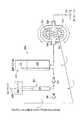
図1〜4は、高圧薬物送達システムの例示的な具体例の概念図である。図1および図5に示されるように、高圧薬物送達システム100は、第一チャンバ111、第二チャンバ121、バルブシステム131および流体接続路141を含む。第一チャンバ111は、送達される薬剤を貯蔵する標準の3mlカートリッジであり得る。標準の3mlカートリッジは、20回分の用量(平均15単位)を保持する。第二チャンバ121は、プランジャ123を有する標準のシリンジであり得る。流体接続路141は、使い捨ての極微針であり得る。バルブシステム131は、第一チャンバ111、第二チャンバ121および流
体接続路141と流体連通する三方弁であり得る。1-4 are conceptual diagrams of exemplary embodiments of a high pressure drug delivery system. As shown in FIGS. 1 and 5, the high-pressure
図1および図5の高圧薬物送達システム100を使用するために、使用者は、三方向弁を用量設定にセットする。用量は、それから、カートリッジのサムホイールを用いてダイアルされ、用量表示窓を通して視認され得る。カートリッジプランジャ113は、それから、シリンジに用量を移送するために押圧され、それによって、シリンジのプランジャ123を上昇させることができる。弁レバーは、それから、注射設定に転じられる。弁レバーが注射設定にあるとき、弁は、カートリッジへの用量の逆流を防止する。使用者は、それから、用量を注射するために、シリンジのプランジャ123を使用する。バルブシステム131は、第一チャンバ111が、薬物の送達と関連した高圧に遭遇することを防止し、それによって、不正確さ、漏れおよび高圧に曝されたカートリッジに関連する他の問題を防止する。 To use the high pressure
図6に示されるように、カートリッジプランジャ113のハンドルは、人間工学的な操作を提供するため、シリンジプランジャ123のハンドル内に入れ子にされる。図7に示されるように、シリンジプランジャ123は、使用者の手に受容できる力を増すため、実質的にT型のハンドルを有し得る。 As shown in FIG. 6, the handle of the
図2に示されるように、高圧薬物送達システム200は、第一チャンバ211、第二チャンバ221、バルブシステム231および流体接続路241を含む。第一チャンバ211は、送達される薬剤を貯蔵する標準の10ml薬剤バイアル瓶であり得る。標準の10ml薬剤バイアル瓶は、薬剤のほぼ3〜4週間の供給量を含む。第二チャンバ221は、プランジャ223を備えた標準のシリンジであり得る。流体接続路241は、使い捨ての極微針であり得る。バルブシステム231は、第一チャンバ211、第二チャンバ221および流体接続路141と流体連通する三方弁であり得る。作動は、用量がシリンジにセットされ、シリンジのプランジャ223がシリンジに用量を引き込むために後退させられることを除いて、図1の高圧薬物送達システムのそれと同じである。加えて、通気口251が第一チャンバ211に接続され、薬剤が第一チャンバ211を出て行くとき、通気口251は、空気が、第一チャンバ211内に引き起こされる真空を防ぐことを可能にする。標準のバイアル瓶は、可動ストッパを備えない、閉鎖された容器である。通気口251は、空気を除いた何もが第一チャンバに入ることを防止する。 As shown in FIG. 2, the high pressure
図3に示されるように、高圧薬物送達システム300は、第一チャンバ311、第二チャンバ321、バルブシステム331および流体接続路341を含む。第一チャンバ311は、送達される薬剤を貯蔵する標準の3mlカートリッジであり得る。標準の3mlカートリッジは、20回分の用量(平均15単位)を保持する。第二チャンバ321は、プランジャ323を備えた標準のシリンジであり得る。流体接続路341は、使い捨ての極微針であり得る。バルブシステム331は、第一チャンバ311、第二チャンバ321と流体連通して配置された第一逆止弁333および第二チャンバ321および流体接続路341と流体連通して配置された第二逆止弁335であり得る。第一逆止弁333は、用量の修正または再設定を可能にするために、手動オーバーライドを有する。 As shown in FIG. 3, the high pressure
図3の高圧薬物送達システム300を使用するために、使用者は、カートリッジのサムホイールを用いて用量をダイアルし、用量は薬剤表示窓を通して視認される。カートリッジプランジャ313は、それから、シリンジに用量を移送するために押圧され、それによって、シリンジプランンジャ313を上昇させることができる。第一逆止弁333は、第一チャンバ311への用量の逆流を防止する。第一逆止弁333は、用量の修正または再設定を可能にするため手動オーバーライドを有し得る。使用者は、それから、第二逆止弁335を通して、および、流体接続路341を通して、薬剤を注射するために、シリンジプランジャ323を使用する。バルブシステム331は、第一チャンバ111を、薬剤の供給に伴う高圧に遭遇することから防止し、それにより、用量の不正確さ、漏れおよび高圧に曝されたカートリッジに関連する他の問題を防止する。 To use the high pressure
上述したように、用量設定メカニズムは、用量とプライムの両方をセットでき、自給式のシステムを提供する。用量がセットされるとき、第二チャンバ321(シリンジ)は、プライムではなく用量のみを受け入れるようにセットされる。シリンジは、シリンジが用量の量のみを受け入れることを可能にする、リミッタを含む。使用者が、シリンジの注入チャンバに、用量およびプライムの双方を押入するとき、プライムは、第二逆止弁335を通して、および、流体接続路341を通して出て行くほかに、行き場を持たず、その結果、高圧送達システムをプライミングする。代わりに、用量は、シリンジのストロークを制限するため、シリンジの側部でセットされ得る。 As mentioned above, the dose setting mechanism can set both dose and prime, providing a self-contained system. When the dose is set, the second chamber 321 (syringe) is set to accept only the dose, not the prime. The syringe includes a limiter that allows the syringe to accept only a dose amount. When the user pushes both the dose and prime into the syringe's injection chamber, the prime has no place to go out through the
図4に示されるように、高圧薬物送達システム400は、第一チャンバ411、第二チャンバ421、バルブシステム431および流体接続路441を含む。第一チャンバ411は、送達される薬剤を貯蔵する標準の10ml薬剤バイアル瓶であり得る。標準の10ml薬剤バイアル瓶は、薬剤のほぼ3〜4週間の供給量を含む。第二チャンバ421は、プランジャ423を備えた標準のシリンジであり得る。流体接続路441は、使い捨ての極微針であり得る。バルブシステム431は、第一チャンバ411、第二チャンバ421と流体連通して配置された第一逆止弁433、および、第二チャンバ421および流体接続路441と流体連通する第二逆止弁435であり得る。第一逆止弁433は、用量の修正または再設定を可能にするために、手動オーバーライドを有する。作動は、用量がシリンジにセットされ、シリンジのプランジャ423がシリンジに用量を引き込むために後退させられることを除いて、図3の高圧薬物送達システムのそれと同じである。加えて、通気口451が第一チャンバ411に接続され、薬剤が第一チャンバ411を出て行くとき、通気口451は、空気が、第一チャンバ411内に引き起こされる真空を防ぐことを可能にする。標準のバイアル瓶は、可動ストッパを備えない、閉鎖された容器である。通気口451は、空気を除いた何もが第一チャンバに入ることを防止する。 As shown in FIG. 4, the high-pressure
図2および図4に示されるように、バイアル瓶をベースにしたシステムは、高圧薬物送達システムと共に使用される。例えば、バイアル瓶は、10mlの容積を有し、それによって、使用者に対するインシュリンのほぼ3〜4週間の供給量を提供する。事前に充填されたバイアル瓶は、より容易に利用可能であり、カートリッジよりも高価でない。加えて、プランジャ式逆止弁がバイアル瓶をベースにしたシステムと共に使用される。 As shown in FIGS. 2 and 4, a vial-based system is used with a high pressure drug delivery system. For example, the vial has a volume of 10 ml, thereby providing approximately 3-4 weeks supply of insulin to the user. Prefilled vials are more readily available and are less expensive than cartridges. In addition, a plunger check valve is used with a vial based system.
図8に示されるようなバイアル瓶をベースにした送達を用いる高圧薬物送達システム500の他の例示的な具体例において、バルブシステム531は、第一チャンバ511(バイアル瓶)および第二チャンバ521(シリンジ)間で流体連通するように配置された手動切替逆止弁であり得る。高圧薬物送達システム500を作動させるために、使用者は、まず、レバー533を用いて「用量セット」の設定に、逆止弁をセットする。それから、用量の大きさと実質的に等量で、空気がシリンジに引かれる。空気は、それから、バイアル瓶に注入される。逆止弁は、それから、レバー533を用いて「注射」の設定に切換えられる。用量は、それから、シリンジに引かれ、インシュリンのみを含む。用量は、それから、使用者に送達される。 In another exemplary embodiment of a high-pressure
逆止弁が、「用量セット」モードにセットされると、逆止弁は、シリンジへの流れを防止する。空気に対して開かれている逆止弁は、真空下で開き、それによって、逆止弁を介してシリンジに空気を引き込む。引き込まれた空気は、それから、バイアル瓶に手動切替逆止弁を通して注入され、それによって、その「用量の空気」でバイアル瓶を加圧する。手動切替逆止弁が「注射」モードに切り替えられると、シリンジは、今やインシュリンだけである用量で再装填される。「注射」モードへの弁の切替は、逆止弁の方向、すなわち、流れの方向を反転させる。二つの逆止弁は、いまや、シリンジから流体接続路(極微針)を通す流れのみを可能にし、その結果、薬液の送達がなされる。 When the check valve is set to “dose set” mode, the check valve prevents flow to the syringe. A check valve that is open to air opens under vacuum, thereby drawing air into the syringe through the check valve. The drawn air is then injected into the vial through a manual switching check valve, thereby pressurizing the vial with its “dose of air”. When the manual switching check valve is switched to the “injection” mode, the syringe is reloaded with a dose that is now only insulin. Switching the valve to the “injection” mode reverses the direction of the check valve, ie the direction of flow. The two check valves now only allow flow from the syringe through the fluid connection (microneedle), resulting in the delivery of the drug solution.
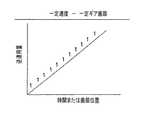
図9に示されるように、所与の直径が「D」の第一チャンバと所与の直径が「d」の第二チャンバに対して、4ポンドの使用者入力を伴う高圧薬物送達システムを実現するための要求される特徴が提供される。 As shown in FIG. 9, for a first chamber with a given diameter “D” and a second chamber with a given diameter “d”, a high pressure drug delivery system with 4 pounds of user input is provided. Required features to implement are provided.
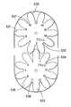
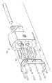
図10〜18に示される、本発明の他の例示的な具体例において、高圧薬物送達システム500は、バイアル瓶511および用量を計測するためのギアポンプアセンブリ521を用いる。図10および図12に示されるように、ギアポンプアセンブリ521への用量入口523の直径は、ギアポンプアセンブリ出口525の直径より大きく、それにより、高圧での排出を提供する。ギアポンプアセンブリ521のギア531および533の各々は、図11に示されるように、プライムポケットを提供するために、深い歯部532および534を含み得る。ギアポンプアセンブリ521のギア531および533の噛合い部は、ギアの歯部に流体を引き込むための空所を生成することによって流体を送り込み、歯部間で流体を運搬し、歯部の噛合い部から高圧で流体を排出する。厳しい精度を有する硬いギア歯部は、高圧での適用を可能にさせる。標準のギアポンプアセンブリ521が図14に示される。 In other exemplary embodiments of the present invention shown in FIGS. 10-18, the high pressure
用量は、図12に示されるように、シリンジ551において、用量スクリュー555でダイアルされ、シリンジプランジャ553を引き上げて、「用量の空気」をシリンジに装填する。シリンジプランジャ553は、それから、シリンジ充填弁571を閉鎖し、バイアル瓶511中に、シリンジ551から空気を送り込むために押し下げられる。シリンダプランジャ553の押し下げは、ギアポンプアセンブリが回転することを可能にし、それによって、バイアル瓶511から、高圧で、極微針のような流体接続路561にインシュリンを引き込む。高圧薬物送達システム500は、1/2単位の正確さで計測するギアポンプアセンブリ521を用いて高圧を発生する。バルブシステム571は、図12および図13に示されるように、送達装置の「空気側」に位置し、「インシュリン側」には位置しない。バイアル瓶511は、インシュリンのほぼ4〜5週間分の供給量を含み、それにより、浪費量を減少する。 The dose is dialed in the
図10に示された、高圧薬物送達装置600の他の例示的な具体例において、用量のセットの間に逆止弁681を通して空気を充填されるシリンジ651は、インシュリンが追い出されるようにバイアル瓶611に圧力を加えるために使用される。用量がセットされ、使用者が注入を開始した後、シリンジ651からの空気は、バイアル瓶内に真空が形成されることを防止するために、逆止弁671を通してバイアル瓶611内に押入される。同時に、シリンジプランジャ655での使用者の下向きの力から発生させられる回転力が、ギアポンプアセンブリ521を回転させ、インシュリンをバイアル瓶611から引き込み、高圧で、流体接続路561に送り込む。 In another exemplary embodiment of the high pressure
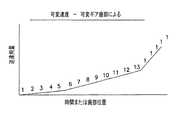
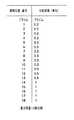
ギアポンプアセンブリ521は、歯部535および536が、歯部535と536の間の空間である、各々の薬剤容積空間またはポケット537および538が、図15および図16に示されているように、各々、1/4または1/2単位容積であるか、計測または用量の正確さのために適切な他の容積であるような大きさとされることを許容する。加えて、第一ポケット532および534は、高圧薬物送達システム500をプライムするために必要とされる容積のための大きさとされる「プライムポケット」として指定される。代わりに、薬剤容積スペースまたはポケット537および538は、それぞれ、各々の歯部535および536に対して同じである必要はない。例えば、図17および図18に示されているように、プライム後の第一容積は、より少量で、それから、だんだんと、用量が大きくなるにつれて、容積を増大させる。このことは、正確さを維持しながら可変速度制御を可能にし、それによって、注射の当初はより遅い注入を、終局では速度アップを可能にする。皮内注射圧力と可変注入速度との一致は、全体的に、背圧を減少し、注射部位からの浸出または流体の漏れの制御を容易にする。 The
バイアル瓶をベースにした送達機器は、より小さい3mlのカートリッジに代えて、より大きい10mlのバイアル瓶が用いられることを可能にし、それによって、利用可能な用量の量を増大させ、多くのより小さいカートリッジの必要性を減少させる。ギアポンプアセンブリ521を用いることによって、高圧を供給するための能力が提供され、その一方で、容量を正確に計測する。ギアポンプアセンブリ521は、また、容量を推進する、捻りバネのような一貫した入力と接続して、可変速度制御を提供する。プライミングは、用量の前に、プライミングが確実に生じるように、プライム容積を保持するために特別な大きさの歯部を提供することによって、ギアの歯部のレイアウトに組み込まれる。 Vial-based delivery devices allow larger 10 ml vials to be used instead of smaller 3 ml cartridges, thereby increasing the amount of available dose and many smaller Reduce the need for cartridges. By using the
図17および図18に示されるように、本発明の例示的な具体例による高圧薬物送達システム500は、可変速度のギアポンプアセンブリを用いる。可変速度は、最初のいくつかのギア歯部の間でのより小さい容積と、その後に続く、より大きい容積を提供することによって実現される。例えば、最初の五つのギアの歯部の間の四つの容積は、各々1単位である残りの容積を有する、インシュリンの第一の単位の量である。注射の最初により遅いインシュリンの流れ速度を提供することの利点は、皮内注射の間の減少された背圧を導く。減少された、または、制御された背圧は、皮内注射に求められる、より少ない漏れおよび減少された力に関して、より受け入れられる注射に導く。 As shown in FIGS. 17 and 18, the high pressure
本発明を説明するために、例示的な具体例が選択されたけれども、添付の特許請求の範囲に規定された発明の範囲から離れることなく、種々の変更および修正がそこになされることは、当業者に理解される。 Although exemplary embodiments have been selected to illustrate the present invention, various changes and modifications may be made thereto without departing from the scope of the invention as defined in the appended claims. It will be understood by those skilled in the art.
Claims (12)
Translated fromJapanese薬剤の供給量を貯蔵するための第一チャンバ、
上記第一チャンバと流体連通する第二チャンバ、
高圧領域に薬剤を送達するために上記第二チャンバと流体連通する流体接続路、および、
上記第一および第二チャンバならびに上記流体接続路と流体連通するバルブシステムを含み、
上記バルブシステムは、上記第一チャンバから上記第二チャンバへ、薬剤の用量が注入されることを許容して、さらに、上記用量の上記第一チャンバへの逆流を実質的に防止すると共に上記流体接続路を通した漏れを防止し、上記バルブシステムは、上記第二チャンバ内の上記用量が上記流体接続路を通して投与されることを可能にし、さらに、上記用量が上記第一チャンバへ逆流することを実質的に防止することを特徴とする薬剤を送達するための高圧送達システム。A high pressure delivery system for delivering a medicament comprising:
A first chamber for storing a supply of drug,
A second chamber in fluid communication with the first chamber;
A fluid connection in fluid communication with the second chamber for delivering a drug to the high pressure region; and
A valve system in fluid communication with the first and second chambers and the fluid connection;
The valve system allows a dose of drug to be injected from the first chamber into the second chamber, and further substantially prevents back flow of the dose into the first chamber and the fluid. Preventing leakage through a connection path, the valve system allows the dose in the second chamber to be administered through the fluid connection path, and further allows the dose to flow back into the first chamber. A high pressure delivery system for delivering a drug characterized by substantially preventing
薬剤の供給量を貯蔵するための第一チャンバ、
上記第一チャンバと流体連通するギアポンプアセンブリであって、上記ギアポンプアセンブリは、用量の入口と用量の排出口を有し、上記用量の入口は、高圧排出を防止するために、上記用量の排出口より大きい直径を有している、上記ギアポンプアセンブリ、および、
高圧領域に薬剤を送達するために上記ギアポンプアセンブリと流体連通する流体接続路を含むことを特徴とする薬剤を送達するための高圧送達システム。A high pressure delivery system for delivering a medicament comprising:
A first chamber for storing a supply of drug,
A gear pump assembly in fluid communication with the first chamber, the gear pump assembly having a dose inlet and a dose outlet, wherein the dose inlet is configured to prevent high pressure discharge. The gear pump assembly having a larger diameter; and
A high pressure delivery system for delivering medication, comprising a fluid connection in fluid communication with the gear pump assembly for delivering medication to a high pressure region.
Applications Claiming Priority (2)
| Application Number | Priority Date | Filing Date | Title |
|---|---|---|---|
| US8205308P | 2008-07-18 | 2008-07-18 | |
| US61/082,053 | 2008-07-18 |
Related Parent Applications (1)
| Application Number | Title | Priority Date | Filing Date |
|---|---|---|---|
| JP2011518736ADivisionJP5892792B2 (en) | 2008-07-18 | 2009-07-17 | Two chamber and gear pump assembly for high pressure drug delivery system |
Related Child Applications (1)
| Application Number | Title | Priority Date | Filing Date |
|---|---|---|---|
| JP2016129193ADivisionJP6306647B2 (en) | 2008-07-18 | 2016-06-29 | Two chamber and gear pump assembly for high pressure drug delivery system |
Publications (2)
| Publication Number | Publication Date |
|---|---|
| JP2014184343Atrue JP2014184343A (en) | 2014-10-02 |
| JP6035287B2 JP6035287B2 (en) | 2016-11-30 |
Family
ID=41550627
Family Applications (3)
| Application Number | Title | Priority Date | Filing Date |
|---|---|---|---|
| JP2011518736AActiveJP5892792B2 (en) | 2008-07-18 | 2009-07-17 | Two chamber and gear pump assembly for high pressure drug delivery system |
| JP2014141687AActiveJP6035287B2 (en) | 2008-07-18 | 2014-07-09 | Two chamber and gear pump assembly for high pressure drug delivery system |
| JP2016129193AActiveJP6306647B2 (en) | 2008-07-18 | 2016-06-29 | Two chamber and gear pump assembly for high pressure drug delivery system |
Family Applications Before (1)
| Application Number | Title | Priority Date | Filing Date |
|---|---|---|---|
| JP2011518736AActiveJP5892792B2 (en) | 2008-07-18 | 2009-07-17 | Two chamber and gear pump assembly for high pressure drug delivery system |
Family Applications After (1)
| Application Number | Title | Priority Date | Filing Date |
|---|---|---|---|
| JP2016129193AActiveJP6306647B2 (en) | 2008-07-18 | 2016-06-29 | Two chamber and gear pump assembly for high pressure drug delivery system |
Country Status (6)
| Country | Link |
|---|---|
| US (3) | US8905970B2 (en) |
| EP (2) | EP2303362B1 (en) |
| JP (3) | JP5892792B2 (en) |
| CA (2) | CA2951841C (en) |
| ES (2) | ES2742550T3 (en) |
| WO (1) | WO2010008575A1 (en) |
Families Citing this family (28)
| Publication number | Priority date | Publication date | Assignee | Title |
|---|---|---|---|---|
| CA2951841C (en) | 2008-07-18 | 2018-07-10 | Becton, Dickinson And Company | Dual chamber and gear pump assembly for a high pressure delivery system |
| WO2012092352A1 (en)* | 2010-12-30 | 2012-07-05 | Cook Medical Technologies Llc | Occlusion device |
| CN103442748B (en)* | 2011-02-19 | 2016-08-10 | 图什医疗有限公司 | Compact Medical Pump Unit |
| US9744292B2 (en)* | 2012-03-07 | 2017-08-29 | Stc.Unm | Infusion device |
| US10086132B2 (en) | 2012-03-07 | 2018-10-02 | Stc.Unm | Infusion device |
| CN204379913U (en) | 2012-04-09 | 2015-06-10 | 贝克顿·迪金森公司 | Medicine bottle dosing mechanism and molectron |
| CN204395138U (en)* | 2012-04-09 | 2015-06-17 | 贝克顿·迪金森公司 | For the induction system of point medicine |
| CA2877900A1 (en)* | 2012-05-25 | 2013-11-28 | Abbott Medical Optics Inc. | Surgical handpiece having directional fluid control capabilities |
| US9867929B2 (en)* | 2012-08-15 | 2018-01-16 | Becton, Dickinson And Company | Pump engine with metering system for dispensing liquid medication |
| WO2014046950A1 (en) | 2012-09-24 | 2014-03-27 | Enable Injections, Llc | Medication vial and injector assemblies and methods of use |
| US9878106B2 (en)* | 2012-10-15 | 2018-01-30 | Elcam Medical Agricultural Cooperative | Multi-chamber syringe |
| EP2908902B1 (en)* | 2012-10-16 | 2018-12-05 | Acist Medical Systems, Inc. | Controlling flow in a medical injection system |
| US9486573B2 (en) | 2013-03-14 | 2016-11-08 | Bayer Healthcare Llc | Fluid delivery system and method of fluid delivery to a patient |
| ES2728054T3 (en) | 2013-06-18 | 2019-10-22 | Enable Injections Inc | Vial transfer and injection device |
| DK2815778T3 (en)* | 2013-06-21 | 2017-11-20 | Hoffmann La Roche | Portable infusion device for children with low volume refillable dosing unit |
| CA2912932A1 (en) | 2013-07-17 | 2015-01-22 | Bayer Medical Care Inc. | Cartridge-based in-bore infuser |
| CA2929410C (en)* | 2013-11-05 | 2021-11-09 | Synagile Corporation | Devices and methods for continuous drug delivery via the mouth |
| CA3009221A1 (en) | 2014-12-23 | 2016-06-30 | Automed Pty Ltd | Delivery apparatus, system and associated methods |
| EP3291872A4 (en) | 2015-05-06 | 2019-02-13 | SynAgile Corporation | PHARMACEUTICAL SUSPENSIONS CONTAINING MEDICINAL PARTICLES, DEVICES FOR THEIR ADMINISTRATION, AND METHODS OF USE |
| US11246984B2 (en)* | 2016-11-01 | 2022-02-15 | Sanofi-Aventis Deutschland Gmbh | Volume measuring arrangement |
| ES2985905T3 (en) | 2016-11-22 | 2024-11-07 | Lts Device Tech Ltd | Apparatus for delivering a therapeutic substance |
| DK3335745T3 (en)* | 2016-12-14 | 2020-02-17 | Hoffmann La Roche | Initialization of outpatient infusion system |
| WO2018232171A1 (en) | 2017-06-15 | 2018-12-20 | Enable Injections, Inc. | Hand-held fluid transfer device and system |
| ES2986346T3 (en) | 2018-10-05 | 2024-11-11 | Lts Device Tech Ltd | Activation sequence |
| CN110124156A (en)* | 2019-06-10 | 2019-08-16 | 舒海华 | A kind of easing pain of electron drug administration device |
| EP3868420A1 (en)* | 2020-02-19 | 2021-08-25 | Ivoclar Vivadent AG | Dosing container for dosing viscous material components |
| US11957542B2 (en) | 2020-04-30 | 2024-04-16 | Automed Patent Holdco, Llc | Sensing complete injection for animal injection device |
| CN112569426A (en)* | 2020-12-24 | 2021-03-30 | 时新(上海)产品设计有限公司 | Dose-controllable medium conveying structure, medium conveying method and micro-dose secretion pump |
Citations (9)
| Publication number | Priority date | Publication date | Assignee | Title |
|---|---|---|---|---|
| US4210173A (en)* | 1976-12-06 | 1980-07-01 | American Hospital Supply Corporation | Syringe pumping system with valves |
| JPH0623044A (en)* | 1992-03-23 | 1994-02-01 | Clintec Nutrition Co | Liquid flow controller |
| US5807312A (en)* | 1997-05-23 | 1998-09-15 | Dzwonkiewicz; Mark R. | Bolus pump apparatus |
| JP2002511317A (en)* | 1998-04-10 | 2002-04-16 | マイルストーン サイアンティフィック インク | Drug administration devices and similar devices with computer control of at least one of pressure and / or force |
| JP2005508679A (en)* | 2001-10-04 | 2005-04-07 | サイムド ライフ システムズ, インコーポレイテッド | Angiographic fluid control system |
| WO2006123329A2 (en)* | 2005-05-17 | 2006-11-23 | Medingo Ltd. | Disposable dispenser for patient infusion |
| JP2006526467A (en)* | 2003-05-30 | 2006-11-24 | イーライ リリー アンド カンパニー | Multiple chamber type dosing device |
| JP2008540117A (en)* | 2005-05-16 | 2008-11-20 | マリンクロッド・インコーポレイテッド | Multi-cylinder syringe with integrated manifold |
| JP2009532112A (en)* | 2006-03-31 | 2009-09-10 | メドラッド インコーポレーテッド | Fluid delivery system with bulk container and pump assembly |
Family Cites Families (68)
| Publication number | Priority date | Publication date | Assignee | Title |
|---|---|---|---|---|
| US1646374A (en)* | 1927-08-04 | 1927-10-18 | John T Wilkin | Gear |
| US2897765A (en)* | 1954-12-07 | 1959-08-04 | Kitano Akitoshi | Driving apparatus comprising modified elliptic gear wheels |
| US3057370A (en) | 1959-09-28 | 1962-10-09 | Baxter Don Inc | Three-way valve |
| US3218984A (en)* | 1965-02-10 | 1965-11-23 | Charles N Mosovsky | Fluid pressure device |
| US3306228A (en)* | 1965-08-20 | 1967-02-28 | Trw Inc | Combination gear and vane pump |
| FR1499582A (en) | 1966-11-02 | 1967-10-27 | Needle-free injection device, especially for administering drug solutions | |
| JPS50702B2 (en)* | 1971-08-28 | 1975-01-10 | ||
| US4106361A (en)* | 1976-10-26 | 1978-08-15 | Wyle Laboratories | Gear pump, gear and method |
| US4130383A (en)* | 1977-06-23 | 1978-12-19 | Borg-Warner Corporation | Apparatus for noise suppression in a gear pump |
| US4253501A (en)* | 1979-11-09 | 1981-03-03 | Ims Limited | Transfer system |
| US4356727A (en)* | 1980-03-07 | 1982-11-02 | Brown Carole E | Continuous volume measuring system |
| GB2135734B (en)* | 1982-09-07 | 1986-01-29 | Ford Motor Co | Helical gear pump |
| US4623301A (en)* | 1984-11-29 | 1986-11-18 | Helios Research Corp. | Overflow check system |
| DE3515624A1 (en) | 1985-04-30 | 1986-11-27 | Karl Dipl.-Phys. 8520 Erlangen Prestele | Medicament metering device having a main store and a metering chamber |
| US4645496A (en)* | 1986-01-09 | 1987-02-24 | Rao Medical Devices, Inc. | Continuous catheter flushing flow control device |
| US4852352A (en)* | 1987-03-05 | 1989-08-01 | Automotive Products Plc | Manual override for relief of pulsator circuit with reservoir ball valve |
| US4915688A (en)* | 1987-12-03 | 1990-04-10 | Baxter International Inc. | Apparatus for administering solution to a patient |
| DE8804229U1 (en)* | 1988-03-29 | 1988-05-11 | Festo KG, 7300 Esslingen | Controllable check valve |
| US5002528A (en)* | 1989-12-15 | 1991-03-26 | Aubrey Palestrant | Percutaneous irrigation and drainage system |
| US5466228A (en)* | 1991-01-25 | 1995-11-14 | California State University, Fresno Foundation | Fluid control apparatus |
| KR940006864B1 (en)* | 1992-01-16 | 1994-07-28 | 구인회 | Cam Gear Pump Unit |
| US5472403A (en)* | 1993-05-11 | 1995-12-05 | The Regents Of The University Of California | Device for automatic injection of radionuclide |
| US5439452A (en)* | 1994-01-31 | 1995-08-08 | Children's Medical Ventures, Inc. | Limit stop valve infusion device |
| US5600951A (en)* | 1994-07-05 | 1997-02-11 | Helver; Oscar | Hydraulic transmission system |
| WO1996001950A1 (en)* | 1994-07-07 | 1996-01-25 | David Brown Hydraulics Limited | Helical gear pump or motor |
| US5406228A (en) | 1994-07-12 | 1995-04-11 | General Instrument | Ring oscillator with frequency control loop |
| US5533978A (en)* | 1994-11-07 | 1996-07-09 | Teirstein; Paul S. | Method and apparatus for uninterrupted delivery of radiographic dye |
| US6099502A (en)* | 1995-04-20 | 2000-08-08 | Acist Medical Systems, Inc. | Dual port syringe |
| KR100373772B1 (en)* | 1995-07-31 | 2003-09-13 | 심영택 | Treatment apparatus for erectile disorder |
| JPH1089443A (en)* | 1996-09-13 | 1998-04-07 | Akitoshi Kitano | Elliptic gear |
| JPH11247767A (en)* | 1997-12-23 | 1999-09-14 | Maag Pump Syst Textron Ag | Positioning method for gear pump shaft, and gear pump |
| JP3915223B2 (en)* | 1998-01-27 | 2007-05-16 | 株式会社島津製作所 | Gear pump or motor |
| JP3948104B2 (en)* | 1998-03-24 | 2007-07-25 | アイシン精機株式会社 | Oil pump |
| JPH11342209A (en)* | 1998-06-03 | 1999-12-14 | Nippon Sherwood Medical Industries Ltd | Medical stopcock |
| US6099511A (en)* | 1999-03-19 | 2000-08-08 | Merit Medical Systems, Inc. | Manifold with check valve positioned within manifold body |
| JP2000337962A (en) | 1999-05-27 | 2000-12-08 | Ando Electric Co Ltd | Spectrograph and optical spectrum-measuring device |
| US6494865B1 (en) | 1999-10-14 | 2002-12-17 | Becton Dickinson And Company | Intradermal delivery device including a needle assembly |
| US6569143B2 (en) | 1999-10-14 | 2003-05-27 | Becton, Dickinson And Company | Method of intradermally injecting substances |
| IL156245A0 (en)* | 2000-12-22 | 2004-01-04 | Dca Design Int Ltd | Drive mechanism for an injection device |
| US20020107501A1 (en)* | 2001-02-02 | 2002-08-08 | Smith James E. | Weight dependent, automatic filling dosage system and method of using same |
| US6622542B2 (en)* | 2001-03-20 | 2003-09-23 | Therox, Inc. | Bubble detector and method of use thereof |
| US6582387B2 (en)* | 2001-03-20 | 2003-06-24 | Therox, Inc. | System for enriching a bodily fluid with a gas |
| US6976974B2 (en)* | 2002-10-23 | 2005-12-20 | Scimed Life Systems, Inc. | Rotary manifold syringe |
| JP3945480B2 (en)* | 2001-11-14 | 2007-07-18 | 株式会社ジェイ・エム・エス | Three-way stopcock and infusion circuit or transfusion circuit using the three-way stopcock |
| AU2003206241A1 (en)* | 2002-02-08 | 2003-09-02 | Kyung-Yul Hyun | Fluid pump and motor |
| DE10222131C5 (en) | 2002-05-17 | 2011-08-11 | Schwäbische Hüttenwerke Automotive GmbH & Co. KG, 73433 | Positive displacement pump with delivery volume adjustment |
| PT1540184E (en)* | 2002-06-03 | 2015-08-20 | M & M Technologies Inc | Gear pump |
| US6953450B2 (en)* | 2002-08-22 | 2005-10-11 | Baxa Corporation | Apparatus and method for administration of IV liquid medication and IV flush solutions |
| FR2848859B1 (en)* | 2002-12-20 | 2005-11-04 | Sedat | DISPENSING DEVICE FOR A NETWORK FOR DELIVERING MEDICAL FLUIDS TO A PATIENT |
| US6997689B2 (en)* | 2003-02-20 | 2006-02-14 | Honeywell International Inc. | Offset bearing for extended fuel pump life |
| WO2004091688A2 (en)* | 2003-04-08 | 2004-10-28 | Medrad, Inc. | Fluid delivery systems, devices and methods for delivery of hazardous fluids |
| US20040210162A1 (en)* | 2003-04-21 | 2004-10-21 | Wyatt Philip W. | Unitary blood sampling apparatus and method of using same |
| EP3695862A1 (en) | 2003-08-12 | 2020-08-19 | Becton, Dickinson and Company | Patch-like infusion device |
| EP1660149B1 (en) | 2003-08-28 | 2018-03-07 | Becton, Dickinson and Company | Intradermal injection device |
| US7004445B2 (en) | 2003-10-27 | 2006-02-28 | Safoco, Inc. | Mechanical override for a valve actuator |
| AU2005212341B2 (en)* | 2004-02-10 | 2011-11-24 | Synecor, Llc. | Intravascular delivery system for therapeutic agents |
| AT501250B1 (en) | 2004-09-22 | 2007-03-15 | Pro Med Medizinische Produktio | DEVICE FOR DOSED RECORDING AND DISTRIBUTION OF LIQUID |
| US20090221914A1 (en)* | 2005-09-14 | 2009-09-03 | Acist Medical Systems, Inc. | Medical Fluid Injection System |
| WO2007053799A2 (en)* | 2005-10-19 | 2007-05-10 | Cd Solutions, Llc | Apparatus and method for mixing and transferring medications |
| US7618397B2 (en)* | 2006-04-12 | 2009-11-17 | Medrad, Inc. | Fluid delivery system with pump cassette |
| US8052856B2 (en) | 2006-12-26 | 2011-11-08 | Kyocera Corporation | Support for capillaries, case for constraining capillaries including the same |
| US20090035121A1 (en)* | 2007-07-31 | 2009-02-05 | Dresser, Inc. | Fluid Flow Modulation and Measurement |
| EP2042096A1 (en)* | 2007-09-27 | 2009-04-01 | F. Hoffmann-La Roche AG | Distribution device for a sample of bodily fluids, fluid extraction and infusion system and operating method |
| US8328787B2 (en)* | 2007-11-29 | 2012-12-11 | Guzman Michael F | Pain management methods and apparatus |
| US8211091B2 (en)* | 2007-11-29 | 2012-07-03 | Guzman Michael F | Method and apparatus for charging pump with local anesthetic |
| CA2951841C (en)* | 2008-07-18 | 2018-07-10 | Becton, Dickinson And Company | Dual chamber and gear pump assembly for a high pressure delivery system |
| US8052656B2 (en)* | 2009-02-10 | 2011-11-08 | Tyco Healthcare Group Lp | Enteral feeding system |
| NO333665B1 (en) | 2011-01-25 | 2013-08-05 | Ts Innovation As | Check valve |
- 2009
- 2009-07-17CACA2951841Apatent/CA2951841C/enactiveActive
- 2009-07-17ESES09798312Tpatent/ES2742550T3/enactiveActive
- 2009-07-17USUS12/737,447patent/US8905970B2/enactiveActive
- 2009-07-17ESES11169439.4Tpatent/ES2666724T3/enactiveActive
- 2009-07-17JPJP2011518736Apatent/JP5892792B2/enactiveActive
- 2009-07-17CACA2730968Apatent/CA2730968C/enactiveActive
- 2009-07-17EPEP09798312.6Apatent/EP2303362B1/enactiveActive
- 2009-07-17EPEP11169439.4Apatent/EP2366414B1/enactiveActive
- 2009-07-17WOPCT/US2009/004132patent/WO2010008575A1/enactiveApplication Filing
- 2014
- 2014-07-09JPJP2014141687Apatent/JP6035287B2/enactiveActive
- 2014-09-05USUS14/478,837patent/US10314967B2/enactiveActive
- 2016
- 2016-06-29JPJP2016129193Apatent/JP6306647B2/enactiveActive
- 2019
- 2019-05-07USUS16/405,037patent/US11383025B2/enactiveActive
Patent Citations (9)
| Publication number | Priority date | Publication date | Assignee | Title |
|---|---|---|---|---|
| US4210173A (en)* | 1976-12-06 | 1980-07-01 | American Hospital Supply Corporation | Syringe pumping system with valves |
| JPH0623044A (en)* | 1992-03-23 | 1994-02-01 | Clintec Nutrition Co | Liquid flow controller |
| US5807312A (en)* | 1997-05-23 | 1998-09-15 | Dzwonkiewicz; Mark R. | Bolus pump apparatus |
| JP2002511317A (en)* | 1998-04-10 | 2002-04-16 | マイルストーン サイアンティフィック インク | Drug administration devices and similar devices with computer control of at least one of pressure and / or force |
| JP2005508679A (en)* | 2001-10-04 | 2005-04-07 | サイムド ライフ システムズ, インコーポレイテッド | Angiographic fluid control system |
| JP2006526467A (en)* | 2003-05-30 | 2006-11-24 | イーライ リリー アンド カンパニー | Multiple chamber type dosing device |
| JP2008540117A (en)* | 2005-05-16 | 2008-11-20 | マリンクロッド・インコーポレイテッド | Multi-cylinder syringe with integrated manifold |
| WO2006123329A2 (en)* | 2005-05-17 | 2006-11-23 | Medingo Ltd. | Disposable dispenser for patient infusion |
| JP2009532112A (en)* | 2006-03-31 | 2009-09-10 | メドラッド インコーポレーテッド | Fluid delivery system with bulk container and pump assembly |
Also Published As
| Publication number | Publication date |
|---|---|
| EP2303362A1 (en) | 2011-04-06 |
| EP2303362B1 (en) | 2019-06-05 |
| EP2366414A2 (en) | 2011-09-21 |
| JP5892792B2 (en) | 2016-03-23 |
| ES2742550T3 (en) | 2020-02-14 |
| US20190255250A1 (en) | 2019-08-22 |
| ES2666724T3 (en) | 2018-05-07 |
| CA2730968C (en) | 2017-01-31 |
| JP6306647B2 (en) | 2018-04-04 |
| EP2303362A4 (en) | 2012-06-13 |
| US11383025B2 (en) | 2022-07-12 |
| CA2730968A1 (en) | 2010-01-21 |
| EP2366414A3 (en) | 2012-06-13 |
| US10314967B2 (en) | 2019-06-11 |
| US20110184348A1 (en) | 2011-07-28 |
| CA2951841C (en) | 2018-07-10 |
| JP2011528574A (en) | 2011-11-24 |
| WO2010008575A1 (en) | 2010-01-21 |
| EP2366414B1 (en) | 2018-02-21 |
| US8905970B2 (en) | 2014-12-09 |
| CA2951841A1 (en) | 2010-01-21 |
| JP6035287B2 (en) | 2016-11-30 |
| JP2016168470A (en) | 2016-09-23 |
| US20150057612A1 (en) | 2015-02-26 |
Similar Documents
| Publication | Publication Date | Title |
|---|---|---|
| JP6306647B2 (en) | Two chamber and gear pump assembly for high pressure drug delivery system | |
| US10653830B2 (en) | Injection mechanism utilizing a vial | |
| US10258749B2 (en) | Multi-stroke delivery pumping mechanism for a drug delivery device for high pressure injections | |
| EP1896099B1 (en) | Injection device with secondary reservoir | |
| EP2355862B1 (en) | Dual-chambered drug delivery device for high pressure injections |
Legal Events
| Date | Code | Title | Description |
|---|---|---|---|
| A621 | Written request for application examination | Free format text:JAPANESE INTERMEDIATE CODE: A621 Effective date:20140806 | |
| A977 | Report on retrieval | Free format text:JAPANESE INTERMEDIATE CODE: A971007 Effective date:20150619 | |
| A131 | Notification of reasons for refusal | Free format text:JAPANESE INTERMEDIATE CODE: A131 Effective date:20150623 | |
| A521 | Request for written amendment filed | Free format text:JAPANESE INTERMEDIATE CODE: A523 Effective date:20150909 | |
| A02 | Decision of refusal | Free format text:JAPANESE INTERMEDIATE CODE: A02 Effective date:20160308 | |
| A521 | Request for written amendment filed | Free format text:JAPANESE INTERMEDIATE CODE: A523 Effective date:20160629 | |
| A911 | Transfer to examiner for re-examination before appeal (zenchi) | Free format text:JAPANESE INTERMEDIATE CODE: A911 Effective date:20160708 | |
| TRDD | Decision of grant or rejection written | ||
| A01 | Written decision to grant a patent or to grant a registration (utility model) | Free format text:JAPANESE INTERMEDIATE CODE: A01 Effective date:20161004 | |
| A61 | First payment of annual fees (during grant procedure) | Free format text:JAPANESE INTERMEDIATE CODE: A61 Effective date:20161031 | |
| R150 | Certificate of patent or registration of utility model | Ref document number:6035287 Country of ref document:JP Free format text:JAPANESE INTERMEDIATE CODE: R150 | |
| R250 | Receipt of annual fees | Free format text:JAPANESE INTERMEDIATE CODE: R250 | |
| R250 | Receipt of annual fees | Free format text:JAPANESE INTERMEDIATE CODE: R250 | |
| R250 | Receipt of annual fees | Free format text:JAPANESE INTERMEDIATE CODE: R250 | |
| R250 | Receipt of annual fees | Free format text:JAPANESE INTERMEDIATE CODE: R250 | |
| R250 | Receipt of annual fees | Free format text:JAPANESE INTERMEDIATE CODE: R250 |