JP2014182028A - Limited area reflection type photoelectric sensor - Google Patents
Limited area reflection type photoelectric sensorDownload PDFInfo
- Publication number
- JP2014182028A JP2014182028AJP2013057188AJP2013057188AJP2014182028AJP 2014182028 AJP2014182028 AJP 2014182028AJP 2013057188 AJP2013057188 AJP 2013057188AJP 2013057188 AJP2013057188 AJP 2013057188AJP 2014182028 AJP2014182028 AJP 2014182028A
- Authority
- JP
- Japan
- Prior art keywords
- light
- light receiving
- photoelectric sensor
- limited area
- reflective photoelectric
- Prior art date
- Legal status (The legal status is an assumption and is not a legal conclusion. Google has not performed a legal analysis and makes no representation as to the accuracy of the status listed.)
- Pending
Links
- 238000001514detection methodMethods0.000claimsabstractdescription118
- 230000003287optical effectEffects0.000claimsabstractdescription68
- 230000008859changeEffects0.000claimsdescription11
- 238000013459approachMethods0.000claimsdescription5
- 230000002123temporal effectEffects0.000claimsdescription5
- 238000009792diffusion processMethods0.000description10
- ORQBXQOJMQIAOY-UHFFFAOYSA-NnobeliumChemical compound[No]ORQBXQOJMQIAOY-UHFFFAOYSA-N0.000description7
- 238000006073displacement reactionMethods0.000description3
- 238000005259measurementMethods0.000description3
- 230000007423decreaseEffects0.000description2
- 230000000694effectsEffects0.000description2
- 238000000034methodMethods0.000description2
- 230000008901benefitEffects0.000description1
- 238000010586diagramMethods0.000description1
- 230000012447hatchingEffects0.000description1
- 230000007257malfunctionEffects0.000description1
- 230000007246mechanismEffects0.000description1
- 238000012986modificationMethods0.000description1
- 230000004048modificationEffects0.000description1
- 230000007480spreadingEffects0.000description1
Images


Classifications
- G—PHYSICS
- G01—MEASURING; TESTING
- G01B—MEASURING LENGTH, THICKNESS OR SIMILAR LINEAR DIMENSIONS; MEASURING ANGLES; MEASURING AREAS; MEASURING IRREGULARITIES OF SURFACES OR CONTOURS
- G01B11/00—Measuring arrangements characterised by the use of optical techniques
- G01B11/14—Measuring arrangements characterised by the use of optical techniques for measuring distance or clearance between spaced objects or spaced apertures
- E—FIXED CONSTRUCTIONS
- E04—BUILDING
- E04H—BUILDINGS OR LIKE STRUCTURES FOR PARTICULAR PURPOSES; SWIMMING OR SPLASH BATHS OR POOLS; MASTS; FENCING; TENTS OR CANOPIES, IN GENERAL
- E04H17/00—Fencing, e.g. fences, enclosures, corrals
- E04H17/14—Fences constructed of rigid elements, e.g. with additional wire fillings or with posts
- E04H17/1408—Fences constructed of rigid elements, e.g. with additional wire fillings or with posts using woven slats
- G—PHYSICS
- G01—MEASURING; TESTING
- G01S—RADIO DIRECTION-FINDING; RADIO NAVIGATION; DETERMINING DISTANCE OR VELOCITY BY USE OF RADIO WAVES; LOCATING OR PRESENCE-DETECTING BY USE OF THE REFLECTION OR RERADIATION OF RADIO WAVES; ANALOGOUS ARRANGEMENTS USING OTHER WAVES
- G01S7/00—Details of systems according to groups G01S13/00, G01S15/00, G01S17/00
- G01S7/48—Details of systems according to groups G01S13/00, G01S15/00, G01S17/00 of systems according to group G01S17/00
- G01S7/4808—Evaluating distance, position or velocity data
- E—FIXED CONSTRUCTIONS
- E04—BUILDING
- E04H—BUILDINGS OR LIKE STRUCTURES FOR PARTICULAR PURPOSES; SWIMMING OR SPLASH BATHS OR POOLS; MASTS; FENCING; TENTS OR CANOPIES, IN GENERAL
- E04H17/00—Fencing, e.g. fences, enclosures, corrals
- E04H17/14—Fences constructed of rigid elements, e.g. with additional wire fillings or with posts
- E04H17/20—Posts therefor
- E—FIXED CONSTRUCTIONS
- E04—BUILDING
- E04H—BUILDINGS OR LIKE STRUCTURES FOR PARTICULAR PURPOSES; SWIMMING OR SPLASH BATHS OR POOLS; MASTS; FENCING; TENTS OR CANOPIES, IN GENERAL
- E04H17/00—Fencing, e.g. fences, enclosures, corrals
- E04H17/14—Fences constructed of rigid elements, e.g. with additional wire fillings or with posts
- E04H17/24—Connections for attaching additional wire to frames, posts or railings
- G—PHYSICS
- G01—MEASURING; TESTING
- G01S—RADIO DIRECTION-FINDING; RADIO NAVIGATION; DETERMINING DISTANCE OR VELOCITY BY USE OF RADIO WAVES; LOCATING OR PRESENCE-DETECTING BY USE OF THE REFLECTION OR RERADIATION OF RADIO WAVES; ANALOGOUS ARRANGEMENTS USING OTHER WAVES
- G01S17/00—Systems using the reflection or reradiation of electromagnetic waves other than radio waves, e.g. lidar systems
- G01S17/02—Systems using the reflection of electromagnetic waves other than radio waves
- G01S17/04—Systems determining the presence of a target
- G—PHYSICS
- G01—MEASURING; TESTING
- G01S—RADIO DIRECTION-FINDING; RADIO NAVIGATION; DETERMINING DISTANCE OR VELOCITY BY USE OF RADIO WAVES; LOCATING OR PRESENCE-DETECTING BY USE OF THE REFLECTION OR RERADIATION OF RADIO WAVES; ANALOGOUS ARRANGEMENTS USING OTHER WAVES
- G01S17/00—Systems using the reflection or reradiation of electromagnetic waves other than radio waves, e.g. lidar systems
- G01S17/02—Systems using the reflection of electromagnetic waves other than radio waves
- G01S17/06—Systems determining position data of a target
- G01S17/46—Indirect determination of position data
- G01S17/48—Active triangulation systems, i.e. using the transmission and reflection of electromagnetic waves other than radio waves
- G—PHYSICS
- G01—MEASURING; TESTING
- G01S—RADIO DIRECTION-FINDING; RADIO NAVIGATION; DETERMINING DISTANCE OR VELOCITY BY USE OF RADIO WAVES; LOCATING OR PRESENCE-DETECTING BY USE OF THE REFLECTION OR RERADIATION OF RADIO WAVES; ANALOGOUS ARRANGEMENTS USING OTHER WAVES
- G01S7/00—Details of systems according to groups G01S13/00, G01S15/00, G01S17/00
- G01S7/48—Details of systems according to groups G01S13/00, G01S15/00, G01S17/00 of systems according to group G01S17/00
- G01S7/481—Constructional features, e.g. arrangements of optical elements
- G01S7/4811—Constructional features, e.g. arrangements of optical elements common to transmitter and receiver
- G01S7/4813—Housing arrangements
- G—PHYSICS
- G01—MEASURING; TESTING
- G01S—RADIO DIRECTION-FINDING; RADIO NAVIGATION; DETERMINING DISTANCE OR VELOCITY BY USE OF RADIO WAVES; LOCATING OR PRESENCE-DETECTING BY USE OF THE REFLECTION OR RERADIATION OF RADIO WAVES; ANALOGOUS ARRANGEMENTS USING OTHER WAVES
- G01S7/00—Details of systems according to groups G01S13/00, G01S15/00, G01S17/00
- G01S7/48—Details of systems according to groups G01S13/00, G01S15/00, G01S17/00 of systems according to group G01S17/00
- G01S7/481—Constructional features, e.g. arrangements of optical elements
- G01S7/4814—Constructional features, e.g. arrangements of optical elements of transmitters alone
- G—PHYSICS
- G01—MEASURING; TESTING
- G01S—RADIO DIRECTION-FINDING; RADIO NAVIGATION; DETERMINING DISTANCE OR VELOCITY BY USE OF RADIO WAVES; LOCATING OR PRESENCE-DETECTING BY USE OF THE REFLECTION OR RERADIATION OF RADIO WAVES; ANALOGOUS ARRANGEMENTS USING OTHER WAVES
- G01S7/00—Details of systems according to groups G01S13/00, G01S15/00, G01S17/00
- G01S7/48—Details of systems according to groups G01S13/00, G01S15/00, G01S17/00 of systems according to group G01S17/00
- G01S7/481—Constructional features, e.g. arrangements of optical elements
- G01S7/4816—Constructional features, e.g. arrangements of optical elements of receivers alone
Landscapes
- Engineering & Computer Science (AREA)
- Physics & Mathematics (AREA)
- General Physics & Mathematics (AREA)
- Remote Sensing (AREA)
- Radar, Positioning & Navigation (AREA)
- Computer Networks & Wireless Communication (AREA)
- Electromagnetism (AREA)
- Architecture (AREA)
- Structural Engineering (AREA)
- Civil Engineering (AREA)
- Geophysics And Detection Of Objects (AREA)
- Optical Radar Systems And Details Thereof (AREA)
- Switches Operated By Changes In Physical Conditions (AREA)
- Electronic Switches (AREA)
- Measurement Of Optical Distance (AREA)
Abstract
Description
Translated fromJapanese本発明は、物体の検知領域が限定された限定領域反射型光電センサに関するものである。 The present invention relates to a limited area reflective photoelectric sensor in which an object detection area is limited.
従来、物体が所定の位置に存在するか否かを検出するための光電センサとして、物体の検知領域が限定された限定領域反射型光電センサが知られている。 Conventionally, as a photoelectric sensor for detecting whether or not an object is present at a predetermined position, a limited area reflective photoelectric sensor in which a detection area of the object is limited is known.
この限定領域反射型光電センサ100は、図13(a)(b)に示すように、発光素子101及び受光素子102を備えており、発光素子101と受光素子102とは、発光素子101から投光ビームを物体検知限定領域Sに向けて照射し、この投光ビームと該物体検知限定領域Sでのみ交差した物体の反射光を受光素子102にて受光可能となるように光軸の角度が設定されている。したがって、ハッチングにて示す物体検知限定領域Sを物体が通過したときには、物体からの反射光を受光素子102にて検出して物体を判別するようになっている。 As shown in FIGS. 13A and 13B, the limited area reflective
詳細には、上記限定領域反射型光電センサ100では、該限定領域反射型光電センサ100からの距離L2〜L4の物体検知限定領域Sに物体が存在する場合には、発光素子101からの投光ビームが物体により正反射され、その正反射された受光ビームが受光素子102に入射される。しかしながら、物体が距離L2〜L4の物体検知限定領域Sの外に存在する場合には、物体は存在しないと判断される。したがって、距離L2〜L4の範囲が物体検出範囲となる。このように、限定領域反射型光電センサ100では、物体が距離L2〜L4の物体検知限定領域Sに到来する場合には、受光素子102に信号が得られるため、この信号に基づいて物体の有無を判別している。 Specifically, in the limited area reflective
ここで、限定領域反射型光電センサ100は、投光ビームと受光ビームとがそれぞれ広がりを有していない場合には、物体を検知して検知信号を出力する動作レベルと、物体が移動して非検知状態となる非動作レベルとの距離の差が小さく、背景の影響も少なくなる。また、発光素子101及び受光素子102の光軸の角度を変化させることによって、検出距離の設定が可能であるという特徴がある。 Here, in the limited area reflection type
このような従来の限定領域反射型光電センサ100は、例えば、近づいてくる物体を検出して一定の位置で停止させるために用いられる。このため、図13(a)(b)に示すように、特に、限定領域反射型光電センサ100から離れた位置である距離L4での投光ビーム及び受光ビームをシャープにする必要がある。 Such a conventional limited area reflective
しかしながら、上記従来の限定領域反射型光電センサでは、検出範囲を広げることができないという問題点を有している。 However, the conventional limited area reflective photoelectric sensor has a problem that the detection range cannot be expanded.
ここで、検出範囲を広げることが可能な光電センサ200として、例えば、特許文献1には、図14に示すように、検出位置Pにおける各被測定面A〜Dをそれぞれ検出するための複数個の反射式光学センサ201A〜201Dを並設し、各々の反射式光学センサ201A〜201Dによって各被測定面A〜Dを個別に検出する手法が開示されている。すなわち、この光電センサ200では、各被測定面A〜Dをそれぞれ検出するために、各反射式光学センサ201A〜201D、各々投光器202と受光器203とを備えており、これによって、結果的に、検出範囲を広げることが可能となっている。 Here, as a
しかしながら、特許文献1に開示された光電センサ200では、被測定面の数に応じたセンサを設ける必要があるので、装置が大型化するという問題点がある。また、各センサを近接設置すると、隣同士のセンサが干渉して、誤動作し易いという問題点もある。 However, in the
本発明は、上記従来の問題点に鑑みなされたものであって、その目的は、検出範囲を広げることにより、被測定面までの距離が変化するような物体を精度よく検出することができ、かつ構成の簡単な限定領域反射型光電センサを提供することを目的としている。 The present invention has been made in view of the above-described conventional problems, and its purpose is to detect an object whose distance to the surface to be measured can be accurately detected by expanding the detection range. It is another object of the present invention to provide a limited area reflective photoelectric sensor having a simple configuration.
本発明の一態様における限定領域反射型光電センサは、上記課題を解決するために、発光素子を有する投光部と受光素子を有する受光部とを備え、上記投光部と受光部とは、該投光部から投光ビームを物体検知領域に向けて照射し、該物体検知限定領域に存在する物体からの反射光による受光ビームを該受光部にて受光可能となるように該投光ビームの光軸と該受光ビームの光軸との交差角度が設定されており、上記受光素子での受光レベルに基づいて物体の有無を判別する限定領域反射型光電センサにおいて、上記発光素子からの投光ビームの光路中に、該投光ビームを複数方向のビームに分割するビーム分割部材が設けられていることを特徴としている。 In order to solve the above problems, a limited area reflective photoelectric sensor according to an aspect of the present invention includes a light projecting unit having a light emitting element and a light receiving unit having a light receiving element, and the light projecting unit and the light receiving unit include: The light projecting beam is emitted from the light projecting unit toward the object detection region, and the light projecting beam is received by the light receiving unit so that the light receiving beam reflected from the object existing in the object detection limited region can be received by the light receiving unit. In a limited area reflective photoelectric sensor that determines the presence or absence of an object based on the light receiving level at the light receiving element, an intersection angle between the optical axis of the light receiving beam and the optical axis of the light receiving beam is set. In the optical path of the light beam, a beam splitting member for splitting the projected beam into beams in a plurality of directions is provided.
上記構成によれば、限定領域反射型光電センサは、発光素子を有する投光部と受光素子を有する受光部とを備え、上記投光部と受光部とは、該投光部から投光ビームを物体検知領域に向けて照射し、該物体検知限定領域に存在する物体からの反射光による受光ビームを該受光部にて受光可能となるように該投光ビームの光軸と該受光ビームの光軸との交差角度が設定されており、上記受光素子での受光レベルに基づいて物体の有無を判別する。 According to the above configuration, the limited area reflection type photoelectric sensor includes the light projecting unit having the light emitting element and the light receiving unit having the light receiving element, and the light projecting unit and the light receiving unit receive the light projecting beam from the light projecting unit. Is directed toward the object detection region, and the light receiving beam by the reflected light from the object existing in the object detection limited region is received by the light receiving unit, and the optical axis of the projected beam and the light receiving beam An intersection angle with the optical axis is set, and the presence / absence of an object is determined based on the light reception level at the light receiving element.
ところで、この種の限定領域反射型光電センサにおいては、投光ビームは単一の光線であるので、物体検知限定領域を広げることができないという問題がある。 By the way, in this kind of limited area reflection type photoelectric sensor, since the light projection beam is a single light beam, there is a problem that the object detection limited area cannot be expanded.
そこで、本発明の一態様では、発光素子からの投光ビームの光路中に、該投光ビームを複数方向のビームに分割するビーム分割部材が設けられている。このため、投光ビームは、ビーム分割部材によって複数方向のビームに分割されるので、投光ビームの光軸と受光ビームの光軸との交差角度の異なる複数種類のビームを生成することができる。このことは、物体との対向方向において複数種類の物体検知限定領域を生成することを意味するものであり、これによって、検出範囲が広がる。そして、検出範囲を広げるために、ビーム分割部材を設けただけであるので、構成は容易である。 Therefore, in one embodiment of the present invention, a beam splitting member that splits the projected beam into beams in a plurality of directions is provided in the optical path of the projected beam from the light emitting element. For this reason, since the light projection beam is split into a plurality of beams by the beam splitting member, a plurality of types of beams having different intersection angles between the optical axis of the light projection beam and the optical axis of the light reception beam can be generated. . This means that a plurality of types of object detection limited regions are generated in the direction facing the object, and the detection range is thereby expanded. Since the beam splitting member is only provided to widen the detection range, the configuration is easy.
したがって、検出範囲を広げることにより、被測定面までの距離が変化するような物体を精度よく検出することができ、かつ構成の簡単な限定領域反射型光電センサを提供することができる。 Therefore, by expanding the detection range, it is possible to provide a limited area reflective photoelectric sensor that can accurately detect an object whose distance to the surface to be measured is changed and that has a simple configuration.
本発明の一態様における限定領域反射型光電センサでは、前記ビーム分割部材は、回折格子からなっていることが好ましい。 In the limited area reflective photoelectric sensor according to one aspect of the present invention, the beam splitting member is preferably formed of a diffraction grating.
これにより、回折格子に投光ビームを照射すると、回折格子からは0次光,±1次光…が出射され、投光ビームが複数方向のビームに分割される。また、回折格子は市販され容易に入手することができる。 Accordingly, when the projection beam is irradiated onto the diffraction grating, zero-order light, ± first-order light,... Are emitted from the diffraction grating, and the projection beam is divided into beams in a plurality of directions. The diffraction grating is commercially available and can be easily obtained.
したがって、ビーム分割部材を安価で構成が簡単な回折格子にて容易に構成することができる。 Therefore, the beam splitting member can be easily configured with a diffraction grating that is inexpensive and has a simple configuration.
本発明の一態様における限定領域反射型光電センサでは、前記受光部は、ビーム分割部材にて複数方向のビームに分割された投光ビームが物体にて反射されたときの複数の受光ビームを受光する一つの複数ビーム受光手段を備えているとすることができる。 In the limited region reflective photoelectric sensor according to one aspect of the present invention, the light receiving unit receives a plurality of light receiving beams when a light projection beam divided into beams in a plurality of directions by a beam dividing member is reflected by an object. One multi-beam light receiving means can be provided.
これにより、一つの複数ビーム受光手段にて、複数の受光ビームを受光するので、受光部における部品点数の削減を図ることができる。 As a result, since a plurality of light receiving beams are received by a single beam receiving means, the number of parts in the light receiving portion can be reduced.
本発明の一態様における限定領域反射型光電センサでは、前記受光部は、ビーム分割部材にて少なくとも3つの方向のビームに分割された投光ビームが物体にて反射されたときの受光ビームのそれぞれを受光する少なくとも3つの単一ビーム光受光手段を備えているとすることができる。 In the limited region reflective photoelectric sensor according to one aspect of the present invention, each of the light-receiving portions is a light-receiving beam obtained when a light-projected beam divided into beams in at least three directions by a beam-splitting member is reflected by an object. It is possible to provide at least three single beam light receiving means for receiving the light.
これにより、限定領域反射型光電センサを、物体の位置を判断する変位センサとして使用することが可能となる。 As a result, the limited area reflective photoelectric sensor can be used as a displacement sensor for determining the position of the object.
本発明の一態様における限定領域反射型光電センサでは、前記発光素子とビーム分割部材との間には、投光ビームを集光する凸レンズが設けられているとすることができる。 In the limited region reflective photoelectric sensor according to one embodiment of the present invention, a convex lens that condenses the light projection beam may be provided between the light emitting element and the beam splitting member.
すなわち、発光素子とビーム分割部材との間に凸レンズを設けることにより、光強度分布を急峻にすることができる。この結果、物体が存在するかの判定のための閾値を容易に設定することができるようになる。 That is, the light intensity distribution can be made steep by providing a convex lens between the light emitting element and the beam splitting member. As a result, it is possible to easily set a threshold value for determining whether an object exists.
本発明の一態様における限定領域反射型光電センサでは、前記投光ビームの光軸と受光ビームの光軸との交差角度を変更する交差角度変更手段が設けられていることが好ましい。 In the limited area reflection type photoelectric sensor according to one aspect of the present invention, it is preferable that a crossing angle changing unit that changes a crossing angle between the optical axis of the light projecting beam and the optical axis of the light receiving beam is provided.
これにより、交差角度変更手段を用いて、投光ビームの光軸と受光ビームの光軸との交差角度を変更することができる。この結果、検出範囲を広げることができ、被測定面までの距離が大きく変化するような物体を精度よく検出することができる。 Thereby, the crossing angle between the optical axis of the light projection beam and the optical axis of the light receiving beam can be changed using the crossing angle changing means. As a result, the detection range can be expanded, and an object whose distance to the surface to be measured changes greatly can be detected with high accuracy.
本発明の一態様における限定領域反射型光電センサでは、前記交差角度変更手段は、前記投光ビームの光軸と受光ビームの光軸との交差角度を変更すべく、前記投光部と受光部との少なくとも一方の傾斜角度を変更する傾斜角度変更手段からなっているとすることができる。 In the limited area reflection type photoelectric sensor according to one aspect of the present invention, the intersecting angle changing unit is configured to change the intersecting angle between the optical axis of the light projecting beam and the optical axis of the light receiving beam. It can be assumed that it comprises an inclination angle changing means for changing at least one of the inclination angles.
これにより、傾斜角度変更手段を用いて投光ビームの光軸と受光ビームの光軸との交差角度を変更する。具体的には、投光部と受光部との少なくとも一方の傾斜角度を変更する。したがって、交差角度を大きく変更することが可能であり、物体検知限定領域の遠近を容易に調整することが可能となる。 Thus, the angle of intersection between the optical axis of the light projecting beam and the optical axis of the light receiving beam is changed using the tilt angle changing means. Specifically, the inclination angle of at least one of the light projecting unit and the light receiving unit is changed. Therefore, the intersection angle can be changed greatly, and the perspective of the object detection limited area can be easily adjusted.
本発明の一態様における限定領域反射型光電センサでは、前記受光部は、入射された投光ビームを正反射させる物体からの受光ビームを受光することが可能である。 In the limited region reflective photoelectric sensor according to one aspect of the present invention, the light receiving unit can receive a received light beam from an object that regularly reflects an incident light projecting beam.
これにより、鏡面反射物体の検出が可能となり、物体の存在有無を確認するだけでなく、後述するように、物体の動きに関する情報を把握することができるようになる。 As a result, the specular reflection object can be detected, and not only the presence / absence of the object can be confirmed, but also information regarding the movement of the object can be grasped as described later.
本発明の一態様における限定領域反射型光電センサでは、前記受光素子での受光レベルの大きさに基づいて、物体までの距離を算出する物体間距離算出手段が設けられていることが好ましい。 In the limited area reflective photoelectric sensor according to one aspect of the present invention, it is preferable that an inter-object distance calculation unit is provided that calculates a distance to an object based on the magnitude of the light receiving level at the light receiving element.
これにより、物体間距離算出手段を用いて、限定領域反射型光電センサと物体との間の距離を算出することが可能となる。 Thus, the distance between the limited area reflective photoelectric sensor and the object can be calculated using the inter-object distance calculation means.
本発明の一態様における限定領域反射型光電センサでは、前記物体が近づいてきたのか又は遠ざかるのかを、前記受光素子での受光レベルの大から小への変化又は小から大への変化のいずれであるかにより検出する物体移動方向検出手段が設けられていることが好ましい。 In the limited area reflective photoelectric sensor according to one aspect of the present invention, whether the object is approaching or moving away is determined by whether the light receiving level at the light receiving element is changed from large to small or small to large. It is preferable that an object moving direction detecting means for detecting whether there is any is provided.
これにより、物体移動方向検出手段を用いて、物体が近づいてきたのか又は遠ざかるのかを、受光素子での受光レベルの大から小への変化又は小から大への変化のいずれであるかにより検出することができる。 As a result, the object moving direction detection means is used to detect whether the object is approaching or moving away, depending on whether the light receiving level at the light receiving element is changed from large to small or small to large. can do.
本発明の一態様における限定領域反射型光電センサでは、前記物体が近づく速度又は遠ざかる速度を前記受光素子の受光レベルの時間的変化に基づいて算出する移動速度算出手段を備えていることが好ましい。 In the limited region reflective photoelectric sensor according to one aspect of the present invention, it is preferable that the limited region reflective photoelectric sensor includes a moving speed calculating unit that calculates a speed at which the object approaches or moves away based on a temporal change in a light receiving level of the light receiving element.
これにより、移動速度算出手段を用いて、物体が近づく速度又は遠ざかる速度を受光素子の受光レベルの時間的変化に基づいて算出することができる。 Thereby, the moving speed calculating means can be used to calculate the speed at which the object approaches or moves away based on the temporal change in the light receiving level of the light receiving element.
本発明の一態様によれば、検出範囲を広げることにより、被測定面までの距離が変化するような物体を精度よく検出することができ、かつ構成の簡単な限定領域反射型光電センサを提供するという効果を奏する。 According to one embodiment of the present invention, there is provided a limited area reflective photoelectric sensor that can accurately detect an object whose distance to a surface to be measured is changed by expanding a detection range and has a simple configuration. The effect of doing.
〔実施の形態1〕
本発明の一実施形態について図1〜図9に基づいて説明すれば、以下のとおりである。[Embodiment 1]
One embodiment of the present invention is described below with reference to FIGS.
本実施の形態の限定領域反射型光電センサは、図2(a)に示すように、物体の段差検知又は用紙の存在の有無検出等の限定した範囲内での物体の有無を検出する場合に利用される。したがって、検出物体からの反射光が正反射又は拡散反射のいずれの場合であっても指定した物体検知限定領域Sの範囲内で、図2(b)に示すように、信号出力の境界が明確となるようにする必要がある。その際、物体検知限定領域Sの範囲は、できるだけ広い方が好ましい。 As shown in FIG. 2A, the limited area reflective photoelectric sensor according to the present embodiment detects the presence or absence of an object within a limited range such as detection of a step of the object or detection of the presence or absence of paper. Used. Therefore, even if the reflected light from the detected object is either regular reflection or diffuse reflection, the boundary of the signal output is clear as shown in FIG. 2B within the range of the designated object detection limited region S. It is necessary to become. At that time, the range of the object detection limited region S is preferably as wide as possible.
すなわち、この種の限定領域反射型光電センサにおいては、投光ビームは単一の光線であるので、物体検知限定領域を広げることができないという問題がある。 That is, in this kind of limited area reflection type photoelectric sensor, since the light projection beam is a single light beam, there is a problem that the object detection limited area cannot be expanded.
そこで、本実施の形態の限定領域反射型光電センサは、このような物体検知限定領域Sをできるだけ広くするために改良されたものとなっている。 Therefore, the limited area reflective photoelectric sensor of the present embodiment has been improved in order to make such an object detection limited area S as wide as possible.
本実施の形態の限定領域反射型光電センサ1Aの構成について、図3に基づいて説明する。図3は本実施の形態の限定領域反射型光電センサ1Aの構成を示す斜視図である。 The configuration of the limited area reflective
本実施の形態の限定領域反射型光電センサ1Aは、図3に示すように、投光部10と受光部20とを備え、これら投光部10及び受光部20がケース2に収容されたものからなっている。 As shown in FIG. 3, the limited area reflection
投光部10は、発光素子としてのレーザーダイオード11と、該レーザーダイオード11の前面に設けられた凸レンズからなる投光用レンズ12及び回折格子13とを備えている。 The
また、受光部20は、受光素子としてのフォトダイオード21と、該フォトダイオード21の前面に設けられた凸レンズからなる受光用レンズ22とを備えている。尚、上記投光用レンズ12及び受光用レンズ22は、本発明においては、省略することができる。 The
上記ケース2における投光用レンズ12及び受光用レンズ22の前面は、ケース開口2aとなっており、投光ビーム及び受光ビームが通過できるようになっている。 The front surface of the
上記投光部10と受光部20とは、投光部10から投光ビームを前記物体検知限定領域Sに向けて照射し、該物体検知限定領域Sに存在する物体からの反射光による受光ビームを受光部20にて受光可能となるように該投光ビームの光軸と該受光ビームの光軸との交差角度が設定されている。そして、限定領域反射型光電センサ1Aは、フォトダイオード21での受光レベルに基づいて物体の有無を判別するようになっている。 The
本実施の形態の限定領域反射型光電センサ1Aでは、投光部10からの投光ビームの光路中に、該投光ビームを複数方向のビームに分割するビーム分割部材としての回折格子13が設けられている。尚、本実施の形態では、ビーム分割部材は回折格子13からなっているが、本発明においては必ずしも回折格子13に限らず、投光ビームを複数方向のビームに分割するものであれば他の部材を用いることができる。 In the limited area reflection type
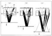
上記構成の限定領域反射型光電センサ1Aにおける物体が存在するかの物体検出方法について、図1(a)(b)(c)及び図4に基づいて説明する。図1(a)(b)(c)は、上記限定領域反射型光電センサを示すものであって、それぞれ異なる物体検知限定領域での物体の検知状態を示す断面図である。図4は、上記限定領域反射型光電センサの構成を示す断面図である。 An object detection method for determining whether or not an object is present in the limited area reflection type
本実施の形態の限定領域反射型光電センサ1Aでは、図4に示すように、投光部10には、該レーザーダイオード11からの投光ビームの光路中に、該投光ビームを複数方向のビームに分割するビーム分割部材としての回折格子13が設けられている。したがって、投光ビームは、回折格子13によって1つの光線が、0次光、±1次光、±2次光、±3次光…というように、複数方向のビームに分割される。このため、投光ビームの光軸と受光ビームの光軸との交差角度の異なる複数種類のビームを生成することができる。ここで、回折格子13は、理論的には±3次光…以降のビームを出射することができるが、現実的には、±3次光…以降のビームは光強度が極度に低下する。このため、使用できるのは、0次光、±1次光、±2次光の5つのビーム程度までであり、実用的な精度の観点からは、0次光及び±1次光までの3つの分割ビームを使用するのが好ましい。 In the limited area reflection type
このことは、物体との対向方向において3種類の物体検知限定領域Sを生成することを意味するものである。すなわち、回折格子13を通過した0次光のビームは、図1(b)に示すように、回折格子13が存在しない場合と同じ物体検知限定領域S1にて、物体Mを検知することができる。一方、回折格子13を通過した±1次光のビームは、図1(a)(c)に示すように、物体検知限定領域S2及び物体検知限定領域S3にて、物体Mを検知することができる。 This means that three types of object detection limited areas S are generated in the direction facing the object. That is, as shown in FIG. 1B, the zero-order light beam that has passed through the
この結果、物体検知限定領域Sは、物体検知限定領域S2〜物体検知限定領域S1〜物体検知限定領域S3まで広がる。すなわち、検出範囲が広がることになる。 As a result, the object detection limited area S extends from the object detection limited area S2 to the object detection limited area S1 to the object detection limited area S3. That is, the detection range is expanded.
ここで、本実施の形態では、物体Mは、入射された投光ビームを正反射させる物体となっている。この結果、鏡面反射物体の検出が可能となる。尚、本実施の形態では、物体Mは、入射された投光ビームを正反射させる物体からなっているが、本発明においては、必ずしもこれに限らず、入射された投光ビームを拡散反射させる物体であってもよい。すなわち、物体Mが拡散反射物体であっても、拡散されたいずれかの受光ビームのフォトダイオード21にて受光できるので、物体Mの検知が可能である。 Here, in the present embodiment, the object M is an object that regularly reflects the incident light projection beam. As a result, it is possible to detect a specular reflection object. In the present embodiment, the object M is an object that regularly reflects the incident light projection beam. However, in the present invention, the present invention is not limited to this, and the incident light projection beam is diffusely reflected. It may be an object. That is, even if the object M is a diffuse reflection object, it can be received by the
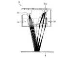
また、本実施の形態では、受光部20のフォトダイオード21についても、種々のものを適用することが可能である。これらの一例について、図5〜図7(a)(b)(c)に基づいて説明する。図5は、上記限定領域反射型光電センサにおいて、受光素子が1個からなる受光部を示す断面図である。図6(a)(b)(c)は、上記限定領域反射型光電センサにおいて、1個の受光素子にて異なる物体検知限定領域の物体を検出する場合の投光ビーム及び受光ビームの光路を示す断面図である。図7(a)(b)(c)は、上記限定領域反射型光電センサにおいて、受光素子が複数個からなる受光部を有する場合の投光ビーム及び受光ビームの光路を示す断面図である。 In the present embodiment, various types of
例えば、フォトダイオード21は、図5に示すように、回折格子13にて複数方向のビームに分割された投光ビームが物体Mにて反射されたときの複数の受光ビームを受光する一つの複数ビーム受光手段としてのフォトダイオード21aとすることが可能である。つまり、受光素子は、1個であるとすることができる。 For example, as shown in FIG. 5, the
これにより、図6(a)に示すように、限定領域反射型光電センサ1Aから最も近い物体検知限定領域S2では回折格子13の−1次光のビームを使用することによりフォトダイオード21aにて受光が可能である。また、図6(b)に示すように、物体検知限定領域S1では回折格子13の0次光のビームを使用することによりフォトダイオード21aにて同一位置にて受光が可能である。さらに、図6(c)に示すように、限定領域反射型光電センサ1Aから最も遠い物体検知限定領域S3では回折格子13の+1次光のビームを使用することによりフォトダイオード21aにて同一位置にて受光が可能である。 As a result, as shown in FIG. 6A, in the object detection limited region S2 closest to the limited region reflective
これに対して、例えば、フォトダイオード21は、図7(a)(b)(c)に示すように、受光部20は、ビーム分割部材にて少なくとも3つの方向のビームに分割された投光ビームが物体Mにて反射されたときの受光ビームのそれぞれを受光する少なくとも3つの単一ビーム光受光手段としてのフォトダイオード21b1・21b2・21b3を備えているとすることが可能である。On the other hand, for example, as shown in FIGS. 7A, 7B, and 7C, the
これにより、図7(a)に示すように、限定領域反射型光電センサ1Aから最も近い物体検知限定領域S2では回折格子13の−1次光のビームを使用することによりフォトダイオード21b1にて受光が可能である。また、図7(b)に示すように、物体検知限定領域S1では回折格子13の0次光のビームを使用することによりフォトダイオード21b2にて同一位置にて受光が可能である。さらに、図7(c)に示すように、限定領域反射型光電センサ1Aから最も遠い物体検知限定領域S3では回折格子13の+1次光のビームを使用することによりフォトダイオード21b3にて同一位置にて受光が可能である。Thereby, as shown in FIG. 7A, in the object detection limited region S2 closest to the limited region reflection type
この結果、フォトダイオード21b1にて信号を検知した場合には物体Mが限定領域反射型光電センサ1Aから最も近い物体検知限定領域S2の位置に存在し、フォトダイオード21b2にて信号を検知した場合には物体Mが物体検知限定領域S1の位置に存在し、フォトダイオード21b3にて信号を検知した場合には物体Mが限定領域反射型光電センサ1Aから最も遠い物体検知限定領域S3の位置に存在していると判断することができる。したがって、限定領域反射型光電センサ1Aを変位センサとして使用することができる。As a result, when the signal is detected by the photodiode 21b1 , the object M is present at the position of the object detection limited region S2 closest to the limited region reflective
ここで、本実施の形態の限定領域反射型光電センサ1Aでは、発光素子としてのレーザーダイオード11とビーム分割部材としての回折格子13との間には、投光ビームを集光する凸レンズからなる投光用レンズ12が設けられているとすることができる。 Here, in the limited area reflection type
すなわち、レーザーダイオード11と回折格子13との間に凸レンズからなる投光用レンズ12を設けることにより、光強度分布を急峻にすることができる。この結果、物体Mが存在するかの判定のための閾値を容易に設定することができるようになる。 That is, by providing the
上記凸レンズからなる投光用レンズ12を設けること及び回折格子13を設けることによる効果について、図8に基づいて説明する。図8は、投光ビームの光路中に凸レンズを設けた集中型、凸レンズを設けない平行型、凹レンズを設けた拡散型、及び本実施の形態の回折格子を設けた限定領域反射型光電センサにおける受光素子での検出信号の分布を示すクラフである。 The effect of providing the
一般的に、フォトダイオード21における検出信号の分布は、図8に示すように、ガウス分布となっているが、信号の検出においては、分布が急峻であることが好ましい。これにより、位置検出における閾値の設定が容易になるためである。この閾値を考慮する際に、凸レンズからなる投光用レンズ12を採用した場合には、図8において集光型としてプロットしているように、信号の立ち上がりが急峻となるので、位置検出における閾値の設定が容易となるというメリットがある。また、図8において平行型としてプロットしているのは、凸レンズからなる投光用レンズ12を使用しない場合を示しているが、凸レンズからなる投光用レンズ12を使用する場合、及び本実施の形態の回折格子13を用いた限定領域反射型光電センサ1Aにおいては、この凸レンズからなる投光用レンズ12を使用しない平行型、及び凹レンズを使用した拡散型よりも、信号検出ピークが急峻となっていることが分かる。尚、本実施の形態の回折格子13を用いた限定領域反射型光電センサ1Aでは、単に凸レンズからなる投光用レンズ12のみを用いた平行型や凹レンズを使用した拡散型よりも、検出範囲が広がっていることが把握できる。 In general, the distribution of the detection signal in the
次に、本実施の形態の限定領域反射型光電センサ1Aにおける物体の物体検知限定領域Sの検出の許容範囲について、図9に基づいて説明する。図9は、投光ビームの光路中に凸レンズを設けた集中型、凸レンズを設けない平行型、凹レンズを設けた拡散型、及び本実施の形態の回折格子を設けた限定領域反射型光電センサにおける物体の検出位置の許容範囲を受光素子での検出信号の分布において角度変動として示すクラフである。 Next, an allowable range of detection of the object detection limited area S of the object in the limited area reflection
本実施の形態の限定領域反射型光電センサ1Aにおける物体Mの物体検知限定領域Sにおける検出位置の許容範囲を、受光素子での検出信号の分布において角度変動として示すと、図9に示すようになる。 When the allowable range of the detection position in the object detection limited region S of the object M in the limited region reflective
この結果、図9から分かるように、本実施の形態の回折格子13を設けた限定領域反射型光電センサ1Aにおける物体Mの物体検知限定領域Sにおける検出位置の許容範囲は、受光素子での検出信号の分布において角度変動として解析すると、凸レンズを設けない平行型、凹レンズを設けた拡散型の場合よりも優れていることが分かる。すなわち、本実施の形態の回折格子13を設けた限定領域反射型光電センサ1Aにおいては、角度特性は、凸レンズを設けない平行型、及び凹レンズを設けた拡散型の場合では、角度の絶対値が増加すると信号の出力が低下するのが把握できる。これに対して、本実施の形態の回折格子13を設けた限定領域反射型光電センサ1Aでは、角度の絶対値が増加しても信号の出力の低下は緩慢である。このことは、物体検知限定領域Sの範囲が、凸レンズを設けない平行型、凹レンズを設けた拡散型の場合よりも拡張していることを示している。したがって、本実施の形態の回折格子13を設けた限定領域反射型光電センサ1Aでは、凸レンズを設けない平行型及び凹レンズを設けた拡散型の場合よりも検出範囲が広がっていることが理解される。尚、投光ビームの光路中に凸レンズを設けた集中型の角度特性は、本実施の形態の回折格子13を設けた限定領域反射型光電センサ1Aの角度特性と略同等であった。 As a result, as can be seen from FIG. 9, the allowable range of the detection position in the object detection limited region S of the object M in the limited region reflection type
次に、本実施の形態の限定領域反射型光電センサ1Aでは、さらに機能を高めるために、例えば、物体検知限定領域Sの位置を変更することが可能である。 Next, in the limited area reflective
すなわち、本実施の形態の限定領域反射型光電センサ1Aでは、物体検知限定領域Sの位置を変更するために、投光ビームの光軸と受光ビームの光軸との交差角度を変更する交差角度変更手段が設けられている。これにより、交差角度変更手段を用いて、投光ビームの光軸と受光ビームの光軸との交差角度を変更することができる。この結果、検出範囲を広げることができ、被測定面までの距離が大きく変化するような物体Mを精度よく検出することができる。 That is, in the limited area reflective
具体的には、交差角度変更手段は、投光ビームの光軸と受光ビームの光軸との交差角度を変更すべく、投光部10と受光部20との少なくとも一方の傾斜角度を変更する傾斜角度変更手段からなっているとすることができる。 Specifically, the crossing angle changing means changes the inclination angle of at least one of the
これにより、傾斜角度変更手段を用いて投光ビームの光軸と受光ビームの光軸との交差角度を変更する。具体的には、投光部10と受光部20との少なくとも一方の傾斜角度を変更する。例えば、投光部10をケース2の側面に図示しない軸を中心として回動可能に取り付けておき、任意の回動位置で固定できるようにしておくことが可能である。この結果、この方法によれば、交差角度を大きく変更することが可能である。したがって、物体検知限定領域Sの遠近を容易に調整することが可能となる。 Thus, the angle of intersection between the optical axis of the light projecting beam and the optical axis of the light receiving beam is changed using the tilt angle changing means. Specifically, the inclination angle of at least one of the
このように、本実施の形態の限定領域反射型光電センサ1Aは、レーザーダイオード11を有する投光部10とフォトダイオード21を有する受光部20とを備え、投光部10と受光部20とは、該投光部10から投光ビームを物体検知限定領域Sに向けて照射し、該物体検知限定領域Sに存在する物体Mからの反射光による受光ビームを該受光部20にて受光可能となるように該投光ビームの光軸と該受光ビームの光軸との交差角度が設定されており、フォトダイオード21での受光レベルに基づいて物体Mの有無を判別する。そして、レーザーダイオード11からの投光ビームの光路中に、該投光ビームを複数方向のビームに分割するビーム分割部材が設けられている。 As described above, the limited area reflective
このため、投光ビームは、ビーム分割部材によって複数方向のビームに分割されるので、投光ビームの光軸と受光ビームの光軸との交差角度の異なる複数種類のビームを生成することができる。このことは、物体Mとの対向方向において複数種類の物体検知限定領域S1・S2・S3を生成することを意味するものであり、これによって、検出範囲が広がる。そして、検出範囲を広げるために、ビーム分割部材を設けただけであるので、構成は容易である。 For this reason, since the light projection beam is split into a plurality of beams by the beam splitting member, a plurality of types of beams having different intersection angles between the optical axis of the light projection beam and the optical axis of the light reception beam can be generated. . This means that a plurality of types of object detection limited regions S1, S2, and S3 are generated in the direction facing the object M, and thereby the detection range is expanded. Since the beam splitting member is only provided to widen the detection range, the configuration is easy.
したがって、検出範囲を広げることにより、被測定面までの距離が変化するような物体Mを精度よく検出することができ、かつ構成の簡単な限定領域反射型光電センサ1Aを提供することができる。 Therefore, by expanding the detection range, it is possible to provide the limited area reflective
また、本実施の形態の限定領域反射型光電センサ1Aでは、ビーム分割部材は、回折格子13からなっている。これにより、回折格子13に投光ビームを照射すると、回折格子13からは0次光,±1次光…が出射され、投光ビームが複数方向のビームに分割される。また、回折格子13は市販され容易に入手することができる。したがって、ビーム分割部材を安価で構成が簡単な回折格子13にて容易に構成することができる。 Further, in the limited area reflective
また、本実施の形態の限定領域反射型光電センサ1Aでは、受光部20は、ビーム分割部材にて複数方向のビームに分割された投光ビームが物体Mにて反射されたときの複数の受光ビームを受光する一つの複数ビーム受光手段としてのフォトダイオード21aを備えている。 Further, in the limited area reflection type
これにより、一つの複数ビーム受光手段としてのフォトダイオード21aにて、複数の受光ビームを受光するので、受光部20における部品点数の削減を図ることができる。 As a result, a plurality of light receiving beams are received by the
また、本実施の形態の限定領域反射型光電センサ1Aでは、受光部20は、ビーム分割部材にて少なくとも3つの方向のビームに分割された投光ビームが物体にて反射されたときの受光ビームのそれぞれを受光する少なくとも3つの単一ビーム光受光手段としてのフォトダイオード21b1・21b2・21b3を備えているとすることが可能である。Further, in the limited area reflection type
これにより、限定領域反射型光電センサ1Aを、物体の位置を判断する変位センサとして使用することができる。 Thereby, limited area reflection type
また、本実施の形態の限定領域反射型光電センサ1Aでは、レーザーダイオード11とビーム分割部材との間には、投光ビームを集光する凸レンズからなる投光用レンズ12が設けられているとすることができる。 In the limited area reflective
すなわち、レーザーダイオード11とビーム分割部材との間に凸レンズからなる投光用レンズ12を設けることにより、光強度分布を急峻にすることができる。この結果、物体Mが存在するかの判定のための閾値を容易に設定することができるようになる。 That is, by providing the
また、本実施の形態の限定領域反射型光電センサ1Aでは、投光ビームの光軸と受光ビームの光軸との交差角度を変更する交差角度変更手段が設けられているとすることができる。これにより、交差角度変更手段を用いて、投光ビームの光軸と受光ビームの光軸との交差角度を変更することができる。この結果、検出範囲を広げることができ、被測定面までの距離が大きく変化するような物体を精度よく検出することができる。 Further, in the limited area reflection type
また、本実施の形態の限定領域反射型光電センサ1Aでは、投光ビームの光軸と受光ビームの光軸との交差角度を変更する交差角度変更手段が設けられているとすることができる。 Further, in the limited area reflection type
これにより、交差角度変更手段を用いて、投光ビームの光軸と受光ビームの光軸との交差角度を変更することができる。この結果、検出範囲を広げることができ、被測定面までの距離が大きく変化するような物体Mを精度よく検出することができる。 Thereby, the crossing angle between the optical axis of the light projection beam and the optical axis of the light receiving beam can be changed using the crossing angle changing means. As a result, the detection range can be expanded, and the object M whose distance to the surface to be measured varies greatly can be detected with high accuracy.
また、本実施の形態の限定領域反射型光電センサ1Aでは、交差角度変更手段は、投光ビームの光軸と受光ビームの光軸との交差角度を変更すべく、投光部10と受光部20との少なくとも一方の傾斜角度を変更する傾斜角度変更手段からなっているとすることができる。 Further, in the limited area reflection type
これにより、傾斜角度変更手段を用いて投光ビームの光軸と受光ビームの光軸との交差角度を変更する。具体的には、投光部10と受光部20との少なくとも一方の傾斜角度を変更する。したがって、交差角度を大きく変更することが可能であり、物体検知限定領域Sの遠近を容易に調整することが可能となる。 Thus, the angle of intersection between the optical axis of the light projecting beam and the optical axis of the light receiving beam is changed using the tilt angle changing means. Specifically, the inclination angle of at least one of the
〔実施の形態2〕
本発明の他の実施の形態について図10〜図12に基づいて説明すれば、以下のとおりである。尚、本実施の形態において説明すること以外の構成は、前記実施の形態1と同じである。また、説明の便宜上、前記の実施の形態1の図面に示した部材と同一の機能を有する部材については、同一の符号を付し、その説明を省略する。[Embodiment 2]
The following will describe another embodiment of the present invention with reference to FIGS. The configurations other than those described in the present embodiment are the same as those in the first embodiment. For convenience of explanation, members having the same functions as those shown in the drawings of the first embodiment are given the same reference numerals, and explanation thereof is omitted.
前記実施の形態1の限定領域反射型光電センサ1Aでは、物体Mが物体検知限定領域S1に存在するか否かの検出を目的とするものであり、物体Mは、正反射物体又は拡散反射物体のいずれであってもよかった。 The limited area reflective
これに対して、本実施の形態の限定領域反射型光電センサ1Bは、物体Mが正反射物体に限定されている。これにより、本実施の形態の限定領域反射型光電センサ1Bでは、物体Mの存在の有無だけでなく、物体Mの距離変動についても把握できるようになっている。 In contrast, in the limited area reflective
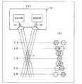
すなわち、本実施の形態の限定領域反射型光電センサ1Bでは、物体Mが正反射物体からなっているので、図10(a)(b)(c)に示すように、フォトダイオード21を用いて物体検知限定領域S1・S2・S3に存在する物体Mを検出することができる。このとき、フォトダイオード21の出力は、図11に示すように、限定領域反射型光電センサ1Bからの距離が近い物体検知限定領域S2・S1・S3の順に大きくなる。したがって、この出力と物体検知限定領域S2・S1・S3の各距離との相関を取っておくことにより、物体Mにおける限定領域反射型光電センサ1Bからの位置を容易に把握することができる。 That is, in the limited area reflection type
また、図12に示すように、物体Mが前後方向に移動したときには、出力が大きい方から小さい方に変化するのか又は出力が小さい方から大きい方に変化するのかによって、物体Mが限定領域反射型光電センサ1Bに対して遠ざかっているのか、又は近づいているのかを把握することができる。 Further, as shown in FIG. 12, when the object M moves in the front-rear direction, the object M is reflected in the limited area depending on whether the output changes from the larger one to the smaller one or the output changes from the smaller one to the larger one. It can be grasped whether it is moving away from or approaching the
具体的には、フォトダイオード21の出力が大きい方から小さい方に変化した場合には、物体Mは遠ざかっており、フォトダイオード21の出力が小さい方から大きい方に変化した場合には、物体Mは近づいていると判断できる。 Specifically, when the output of the
また、物体Mが前後方向に移動する場合に、その距離の移動に要する時間を測定しておけば、容易に物体Mの移動速度を求めることが可能となる。 Further, when the object M moves in the front-rear direction, the moving speed of the object M can be easily obtained by measuring the time required to move the distance.
このように、本実施の形態の限定領域反射型光電センサ1Bでは、受光部20は、入射された投光ビームを正反射させる物体Mからの受光ビームを受光することが可能である。 Thus, in the limited area reflective
これにより、鏡面反射物体の検出が可能となり、物体Mの存在有無を確認するだけでなく、物体Mの動きに関する情報を把握することができるようになる。 As a result, it becomes possible to detect a specular reflection object, and not only the presence / absence of the object M but also information regarding the movement of the object M can be grasped.
また、本実施の形態の限定領域反射型光電センサ1Bでは、フォトダイオード21での受光レベルの大きさに基づいて、物体Mまでの距離を算出する物体間距離算出手段が設けられているとすることができる。 Further, it is assumed that the limited area reflection type
これにより、物体間距離算出手段を用いて、限定領域反射型光電センサ1Bと物体Mとの間の距離を算出することが可能となる。 Thereby, it is possible to calculate the distance between the limited area reflective
また、本実施の形態の限定領域反射型光電センサ1Bでは、物体Mが近づいてきたのか又は遠ざかるのかを、フォトダイオード21での受光レベルの大から小への変化又は小から大への変化のいずれであるかにより検出する物体移動方向検出手段が設けられているとすることができる。 Further, in the limited area reflection type
これにより、物体移動方向検出手段を用いて、物体が近づいてきたのか又は遠ざかるのかを、フォトダイオード21での受光レベルの大から小への変化又は小から大への変化のいずれであるかにより検出することができる。 Thus, whether the object is approaching or moving away using the object moving direction detection means depends on whether the light reception level at the
また、本実施の形態の限定領域反射型光電センサ1Bでは、物体Mが近づく速度又は遠ざかる速度をフォトダイオード21の受光レベルの時間的変化に基づいて算出する移動速度算出手段を備えているとすることができる。 Further, the limited area reflective
これにより、移動速度算出手段を用いて、物体Mが近づく速度又は遠ざかる速度をフォトダイオード21の受光レベルの時間的変化に基づいて算出することができる。 Thereby, the moving speed calculating means can be used to calculate the speed at which the object M approaches or moves away based on the temporal change in the light receiving level of the
尚、本発明は、上述した各実施形態に限定されるものではなく、請求項に示した範囲で種々の変更が可能であり、異なる実施形態にそれぞれ開示された技術的手段を適宜組み合わせて得られる実施形態についても本発明の技術的範囲に含まれる。 The present invention is not limited to the above-described embodiments, and various modifications can be made within the scope of the claims, and the technical means disclosed in different embodiments can be appropriately combined. Such embodiments are also included in the technical scope of the present invention.
本発明は、物体の検知領域が限定された限定領域反射型光電センサに適用することができる。具体的には、物体の段差検知又は用紙の存在の有無検出等の限定した範囲内での物体の有無を検出する場合に利用される。さらに、物体検知限定領域における物体の移動情報を把握する場合にも適用することができる。 The present invention can be applied to a limited area reflective photoelectric sensor in which an object detection area is limited. Specifically, it is used when detecting the presence or absence of an object within a limited range, such as detection of a step of an object or detection of the presence or absence of a sheet. Further, the present invention can be applied to grasping movement information of an object in the object detection limited area.
1A 限定領域反射型光電センサ
1B 限定領域反射型光電センサ
2 ケース
2a ケース開口
10 投光部
11 レーザーダイオード(発光素子)
12 投光用レンズ(凸レンズ)
13 回折格子
20 受光部
21 フォトダイオード(受光素子)
21a フォトダイオード(受光素子)
21b1 フォトダイオード(受光素子)
21b2 フォトダイオード(受光素子)
21b3 フォトダイオード(受光素子)
22 受光用レンズDESCRIPTION OF
12 Projection lens (convex lens)
13
21a Photodiode (light receiving element)
21b1 photodiode (light receiving element)
21b2 photodiode (light receiving element)
21b3 photodiode (light receiving element)
22 Light receiving lens
Claims (11)
Translated fromJapanese上記発光素子からの投光ビームの光路中に、該投光ビームを複数方向のビームに分割するビーム分割部材が設けられていることを特徴とする限定領域反射型光電センサ。A light projecting unit having a light emitting element and a light receiving unit having a light receiving element, wherein the light projecting unit and the light receiving unit irradiate a light projecting beam from the light projecting unit toward an object detection limited region, and detect the object The intersection angle between the optical axis of the light projection beam and the optical axis of the light receiving beam is set so that the light receiving beam by the reflected light from the object existing in the limited region can be received by the light receiving unit, In a limited area reflective photoelectric sensor that determines the presence or absence of an object based on the light reception level at the light receiving element,
A limited area reflective photoelectric sensor, wherein a beam splitting member for splitting the projected beam into beams in a plurality of directions is provided in an optical path of the projected beam from the light emitting element.
Priority Applications (5)
| Application Number | Priority Date | Filing Date | Title |
|---|---|---|---|
| JP2013057188AJP2014182028A (en) | 2013-03-19 | 2013-03-19 | Limited area reflection type photoelectric sensor |
| KR1020140003762AKR101545075B1 (en) | 2013-03-19 | 2014-01-13 | Reflective photoelectric sensor for confined area |
| EP14151047.9AEP2781931A3 (en) | 2013-03-19 | 2014-01-14 | Limited reflection type photoelectric sensor |
| CN201410018123.8ACN104062690A (en) | 2013-03-19 | 2014-01-15 | Limited Reflection Type Photoelectric Sensor |
| US14/167,663US20140285817A1 (en) | 2013-03-19 | 2014-01-29 | Limited reflection type photoelectric sensor |
Applications Claiming Priority (1)
| Application Number | Priority Date | Filing Date | Title |
|---|---|---|---|
| JP2013057188AJP2014182028A (en) | 2013-03-19 | 2013-03-19 | Limited area reflection type photoelectric sensor |
Publications (1)
| Publication Number | Publication Date |
|---|---|
| JP2014182028Atrue JP2014182028A (en) | 2014-09-29 |
Family
ID=49989521
Family Applications (1)
| Application Number | Title | Priority Date | Filing Date |
|---|---|---|---|
| JP2013057188APendingJP2014182028A (en) | 2013-03-19 | 2013-03-19 | Limited area reflection type photoelectric sensor |
Country Status (5)
| Country | Link |
|---|---|
| US (1) | US20140285817A1 (en) |
| EP (1) | EP2781931A3 (en) |
| JP (1) | JP2014182028A (en) |
| KR (1) | KR101545075B1 (en) |
| CN (1) | CN104062690A (en) |
Cited By (1)
| Publication number | Priority date | Publication date | Assignee | Title |
|---|---|---|---|---|
| JP2020046341A (en)* | 2018-09-20 | 2020-03-26 | パイオニア株式会社 | Light projecting device, light projecting receiving device, and distance measuring device |
Families Citing this family (16)
| Publication number | Priority date | Publication date | Assignee | Title |
|---|---|---|---|---|
| US11860292B2 (en) | 2016-11-17 | 2024-01-02 | Trinamix Gmbh | Detector and methods for authenticating at least one object |
| US10948567B2 (en) | 2016-11-17 | 2021-03-16 | Trinamix Gmbh | Detector for optically detecting at least one object |
| CN106679629B (en)* | 2017-01-13 | 2021-03-23 | 西南交通大学 | A ruler-type level based on grating diffraction and a method for measuring the inclination of an inclined plane |
| JP6878931B2 (en)* | 2017-02-08 | 2021-06-02 | オムロン株式会社 | Sensor control device and sensor system |
| JP2020510820A (en) | 2017-03-16 | 2020-04-09 | トリナミクス ゲゼルシャフト ミット ベシュレンクテル ハフツング | Detector for optically detecting at least one object |
| KR102044518B1 (en)* | 2017-06-13 | 2019-11-13 | 주식회사 아모센스 | Window cover and sensor package |
| CN107329589B (en)* | 2017-06-29 | 2020-03-27 | 努比亚技术有限公司 | Control device of function key |
| CN111033300B (en) | 2017-08-28 | 2024-02-09 | 特里纳米克斯股份有限公司 | Distance meter used to determine at least one piece of geometric information |
| CN111344592B (en) | 2017-08-28 | 2023-07-18 | 特里纳米克斯股份有限公司 | Detector for determining position of at least one object |
| JP6925216B2 (en)* | 2017-09-28 | 2021-08-25 | アズビル株式会社 | Photoelectric sensor |
| US10932072B2 (en) | 2018-05-01 | 2021-02-23 | Analog Devices, Inc. | Optical measurement of displacement |
| US10955544B2 (en)* | 2018-06-14 | 2021-03-23 | Rohde & Schwarz Gmbh & Co. Kg | Measurement setup, reference reflector as well as method for measuring attenuation |
| CN110118971B (en)* | 2019-04-26 | 2020-12-18 | 华中科技大学 | Laser triangulation ranging device and method based on grating multi-order diffraction CCD segment multiplexing |
| JP7718178B2 (en)* | 2021-08-27 | 2025-08-05 | 株式会社島津製作所 | Electronic balance |
| CN116381705B (en)* | 2023-04-04 | 2025-08-26 | 松下神视电子(苏州)有限公司 | Sensor, sensor detection method, and computer-readable storage medium |
| CN120274653B (en)* | 2025-06-09 | 2025-08-29 | 绵阳师范学院 | Measurement device for measuring vertical height of forest carbon sink tree |
Family Cites Families (14)
| Publication number | Priority date | Publication date | Assignee | Title |
|---|---|---|---|---|
| JPS5931814B2 (en)* | 1978-06-19 | 1984-08-04 | オムロン株式会社 | reflective photoelectric switch |
| US4948258A (en)* | 1988-06-27 | 1990-08-14 | Harbor Branch Oceanographic Institute, Inc. | Structured illumination surface profiling and ranging systems and methods |
| DE4007500A1 (en)* | 1990-03-09 | 1991-09-12 | Zeiss Carl Fa | METHOD AND DEVICE FOR CONTACTLESS MEASUREMENT OF OBJECT SURFACES |
| DE4040225C2 (en)* | 1990-12-15 | 1994-01-05 | Leuze Electronic Gmbh & Co | Diffuse sensors |
| JPH06102343A (en)* | 1992-09-17 | 1994-04-15 | Hitachi Ltd | Object state detection method and apparatus, and distance measuring method and apparatus using the same |
| JP3270176B2 (en) | 1993-02-18 | 2002-04-02 | ローム株式会社 | Triangular ranging photoelectric sensor |
| AU2921795A (en)* | 1994-07-08 | 1996-02-09 | Forskningscenter Riso | An optical measurement method and apparatus |
| JP2002236003A (en)* | 2000-12-05 | 2002-08-23 | Hitachi Electronics Eng Co Ltd | Micro height measuring device |
| JP4033781B2 (en) | 2002-05-29 | 2008-01-16 | シャープ株式会社 | Optical object identification device, processing system, and conveyance processing system |
| USRE44331E1 (en)* | 2004-02-02 | 2013-07-02 | Livy SRVCS, Limited Liability Company | Vehicle collision detector |
| JP2005241340A (en)* | 2004-02-25 | 2005-09-08 | Sharp Corp | Multi rangefinder |
| JP2005345328A (en)* | 2004-06-04 | 2005-12-15 | Sharp Corp | Optical object identification device |
| US7375801B1 (en)* | 2005-04-13 | 2008-05-20 | The United States Of America As Represented By The Administrator Of The National Aeronautics And Space Administration | Video sensor with range measurement capability |
| US7489408B2 (en)* | 2005-11-15 | 2009-02-10 | General Electric Company | Optical edge break gage |
- 2013
- 2013-03-19JPJP2013057188Apatent/JP2014182028A/enactivePending
- 2014
- 2014-01-13KRKR1020140003762Apatent/KR101545075B1/enactiveActive
- 2014-01-14EPEP14151047.9Apatent/EP2781931A3/ennot_activeWithdrawn
- 2014-01-15CNCN201410018123.8Apatent/CN104062690A/enactivePending
- 2014-01-29USUS14/167,663patent/US20140285817A1/ennot_activeAbandoned
Cited By (1)
| Publication number | Priority date | Publication date | Assignee | Title |
|---|---|---|---|---|
| JP2020046341A (en)* | 2018-09-20 | 2020-03-26 | パイオニア株式会社 | Light projecting device, light projecting receiving device, and distance measuring device |
Also Published As
| Publication number | Publication date |
|---|---|
| EP2781931A2 (en) | 2014-09-24 |
| KR20140114742A (en) | 2014-09-29 |
| CN104062690A (en) | 2014-09-24 |
| KR101545075B1 (en) | 2015-08-17 |
| US20140285817A1 (en) | 2014-09-25 |
| EP2781931A3 (en) | 2014-12-24 |
Similar Documents
| Publication | Publication Date | Title |
|---|---|---|
| JP2014182028A (en) | Limited area reflection type photoelectric sensor | |
| JP5100266B2 (en) | Encoder | |
| JP5795532B2 (en) | Laser self-mixing measuring device | |
| US10281301B2 (en) | Reference mark detector arrangement | |
| JP2003515153A5 (en) | ||
| KR20140018972A (en) | Position detector and light deflection apparatus | |
| US20160231143A1 (en) | Position measurement encoder | |
| JP2019117386A5 (en) | Encoder apparatus and exposure apparatus | |
| US11703571B2 (en) | Optical device | |
| JP5295900B2 (en) | Tilt sensor | |
| JP2020012784A (en) | Optical angle sensor | |
| JP7572834B2 (en) | Optical position measuring device | |
| US9739598B2 (en) | Device for interferential distance measurement | |
| US10591321B2 (en) | Optical encoder | |
| JP4388907B2 (en) | Moving object detection device and speed measurement device | |
| JP2017167145A (en) | Optical distance sensor and position measuring device including optical distance sensor | |
| ATE453851T1 (en) | OPTICAL SENSOR FOR MEASURING THE DISTANCE AND INCLINE OF A SURFACE | |
| JP2007178281A (en) | Tilt sensor and encoder | |
| JP4548162B2 (en) | Moving object detection device and speed measurement device | |
| JP2004347465A (en) | Photoelectric encoder | |
| JP2008089420A (en) | Moving speed detector | |
| JP2022087516A (en) | Displacement sensor and shape measurement device | |
| JPH08105709A (en) | Optical sensor | |
| JPH11183200A (en) | Optical encoder device | |
| JP2012233755A (en) | Optical encoder and absolute position detecting method for the same |
Legal Events
| Date | Code | Title | Description |
|---|---|---|---|
| RD04 | Notification of resignation of power of attorney | Free format text:JAPANESE INTERMEDIATE CODE: A7424 Effective date:20151023 | |
| RD03 | Notification of appointment of power of attorney | Free format text:JAPANESE INTERMEDIATE CODE: A7423 Effective date:20151028 |