JP2014181927A - Information provision device, and information provision program - Google Patents
Information provision device, and information provision programDownload PDFInfo
- Publication number
- JP2014181927A JP2014181927AJP2013054785AJP2013054785AJP2014181927AJP 2014181927 AJP2014181927 AJP 2014181927AJP 2013054785 AJP2013054785 AJP 2013054785AJP 2013054785 AJP2013054785 AJP 2013054785AJP 2014181927 AJP2014181927 AJP 2014181927A
- Authority
- JP
- Japan
- Prior art keywords
- area
- guidance
- line
- sight
- information
- Prior art date
- Legal status (The legal status is an assumption and is not a legal conclusion. Google has not performed a legal analysis and makes no representation as to the accuracy of the status listed.)
- Pending
Links
- 238000001514detection methodMethods0.000claimsdescription9
- 230000006866deteriorationEffects0.000abstract2
- 238000000034methodMethods0.000description34
- 230000006870functionEffects0.000description32
- 238000010586diagramMethods0.000description24
- 230000008569processEffects0.000description23
- 230000010365information processingEffects0.000description14
- 230000000007visual effectEffects0.000description11
- 210000001508eyeAnatomy0.000description9
- 238000004364calculation methodMethods0.000description6
- 238000003384imaging methodMethods0.000description6
- 230000015654memoryEffects0.000description5
- 230000005540biological transmissionEffects0.000description4
- 210000003128headAnatomy0.000description4
- 230000008859changeEffects0.000description3
- 238000005516engineering processMethods0.000description3
- 210000001747pupilAnatomy0.000description3
- 235000002673Dioscorea communisNutrition0.000description2
- 241000544230Dioscorea communisSpecies0.000description2
- 208000035753Periorbital contusionDiseases0.000description2
- 238000004891communicationMethods0.000description2
- 230000007423decreaseEffects0.000description2
- 239000000284extractSubstances0.000description2
- 230000003287optical effectEffects0.000description2
- 238000003909pattern recognitionMethods0.000description2
- 230000002093peripheral effectEffects0.000description2
- 238000001028reflection methodMethods0.000description2
- 230000004044responseEffects0.000description2
- 238000005070samplingMethods0.000description2
- 230000001133accelerationEffects0.000description1
- 210000005252bulbus oculiAnatomy0.000description1
- 210000004087corneaAnatomy0.000description1
- 239000013078crystalSubstances0.000description1
- 230000000694effectsEffects0.000description1
- 238000000605extractionMethods0.000description1
- 230000012447hatchingEffects0.000description1
- 239000004973liquid crystal related substanceSubstances0.000description1
- 230000009467reductionEffects0.000description1
- 239000004065semiconductorSubstances0.000description1
- 230000001502supplementing effectEffects0.000description1
- 238000012876topographyMethods0.000description1
- 230000003936working memoryEffects0.000description1
Images


Landscapes
- Navigation (AREA)
- Digital Computer Display Output (AREA)
- User Interface Of Digital Computer (AREA)
Abstract
Description
Translated fromJapanese本発明は、情報提供装置、及び情報提供プログラムに関し、例えば、車両の運転者に情報を提供するものに関する。 The present invention relates to an information providing apparatus and an information providing program, and relates to, for example, an apparatus that provides information to a driver of a vehicle.
従来の車両用のナビゲーション装置は、運転席付近に設置した小型タッチパネル画面や車内のスピーカやマイクロフォンなどを用いて、運転者(ドライバ)からの入力を受け付けたり、道順や道路情報、商業施設の情報などの案内情報を提供したりしている。
そして、近年では、特許文献1の「車両情報表示システム」のように、ヘッドアップディスプレイ(HUD)を用いた情報提供が試みられるようになってきた。
この技術は、フロントガラスに画像などを投影することにより、運転者の前方に案内情報を表示するものである。
この技術により、運転者は、タッチパネル画面を見ることなく、所望の案内情報を得ることができる。Conventional vehicle navigation devices use a small touch panel screen installed near the driver's seat, in-car speakers, microphones, etc. to accept input from the driver (driver), directions, road information, commercial facility information Or provide guidance information.
In recent years, attempts have been made to provide information using a head-up display (HUD) as in the “vehicle information display system” of
This technology displays guidance information in front of the driver by projecting an image or the like on the windshield.
With this technology, the driver can obtain desired guidance information without looking at the touch panel screen.
ところで、特許文献1記載の技術は、ヘッドアップディスプレイに案内情報を表示させる際に、情報ごとに予め設定された領域に表示し、これを運転者に視認させている。
このように、従来の技術では、案内情報を外部環境に応じて予め決めた位置に表示しているが、情報によっては、フロントガラスの端に表示されるなどし、運転者の視線移動が多くて視認性が悪いという問題があった。By the way, when displaying the guidance information on the head-up display, the technique described in
As described above, in the conventional technology, the guidance information is displayed at a predetermined position according to the external environment. However, depending on the information, the guidance information is displayed on the edge of the windshield, and the driver's line of sight is often moved. There was a problem that visibility was bad.
本発明は、視線移動による視認性の低下を抑制することを目的とする。 An object of this invention is to suppress the fall of the visibility by a line-of-sight movement.
本発明は、前記目的を達成するために、請求項1に記載の発明では、車両の前方方向にある案内対象を特定する特定手段と、前記特定した案内対象の案内情報を取得する案内情報取得手段と、前記車両の運転者の視界において、前記取得した案内情報に対して予め設定された表示領域を取得する表示領域取得手段と、前記運転者の視界に存在する特定対象を検知する検知手段と、前記検知した特定対象が前記視界において占める特定対象領域を設定する設定手段と、前記取得した表示領域のうち、前記設定した特定対象領域と重ならない領域に前記取得した案内情報を表示する表示手段と、を具備したことを特徴とする情報提供装置を提供する。
請求項2に記載の発明では、前記取得した表示領域が、前記運転者の視界において、前記特定した案内対象と重なる領域に設定されていることを特徴とする請求項1に記載の情報提供装置を提供する。
請求項3に記載の発明では、前記取得した表示領域のうち、前記設定した特定対象領域と重ならない領域の面積が所定の規定値を下回る場合、前記表示手段は、前記取得した表示領域、及び設定した特定対象領域の領域外に前記案内情報を表示することを特徴とする請求項1、又は請求項2に記載の情報提供装置を提供する。
請求項4に記載の発明では、前記運転者の視線を検出する視線検出手段と、前記検出した視線の履歴を記憶する視線履歴記憶手段と、前記記憶した履歴を用いて、前記視界を、視線の頻度によって複数の視線領域に区分する区分手段と、を具備し、前記表示手段は、前記領域外に前記案内情報を表示する場合、所定の視線領域に表示することを特徴とする請求項3に記載の情報提供装置を提供する。
請求項5に記載の発明では、前記所定の視線領域の面積が前記案内情報を表示するための所定の面積を満たさない場合、前記表示手段は、より頻度の低い視線領域に前記案内情報を表示することを特徴とする請求項4に記載の情報提供装置を提供する。
請求項6に記載の発明では、前記案内情報が、属性により組分けされており、前記表示手段は、当該属性の組に従って、前記表示する視線領域を選択することを特徴とする請求項5に記載の情報提供装置を提供する。
請求項7に記載の発明では、前記表示手段が、前記案内情報を表示する領域に応じて当該案内情報の表示画像を変化させることを特徴とする請求項3から請求項6までのうちの何れか1の請求項に記載の情報提供装置を提供する。
請求項8に記載の発明では、車両の前方方向にある案内対象を特定する特定機能と、前記特定した案内対象の案内情報を取得する案内情報取得機能と、前記車両の運転者の視界において、前記取得した案内情報に対して予め設定された表示領域を取得する表示領域取得機能と、前記運転者の視界に存在する特定対象を検知する検知機能と、前記検知した特定対象が前記視界において占める特定対象領域を設定する設定機能と、前記取得した表示領域のうち、前記設定した特定対象領域と重ならない領域に前記取得した案内情報を表示する表示機能と、をコンピュータで実現する情報提供プログラムを提供する。In order to achieve the above object, according to the first aspect of the present invention, in the first aspect of the present invention, specifying means for specifying a guidance target in the forward direction of the vehicle, and guidance information acquisition for acquiring the guidance information of the specified guidance target Means, a display area obtaining means for obtaining a display area preset for the obtained guidance information, and a detecting means for detecting a specific target existing in the driver's view. And setting means for setting a specific target area occupied by the detected specific target in the field of view, and a display for displaying the acquired guidance information in an area that does not overlap the set specific target area among the acquired display areas And an information providing apparatus characterized by comprising: means.
According to a second aspect of the present invention, in the information providing apparatus according to the first aspect, the acquired display area is set in an area overlapping the identified guidance object in the driver's field of view. I will provide a.
In the invention according to
According to a fourth aspect of the present invention, the line of sight is detected using the line of sight detecting means for detecting the driver's line of sight, the line of sight history storing means for storing the history of the detected line of sight, and the stored history. And a display unit for dividing the information into a plurality of line-of-sight areas according to the frequency of the display, wherein the display means displays the guidance information outside the area in a predetermined line-of-sight area. The information providing apparatus described in 1. is provided.
According to a fifth aspect of the present invention, when the area of the predetermined line-of-sight area does not satisfy the predetermined area for displaying the guidance information, the display means displays the guidance information in a line-of-sight area that is less frequent. An information providing apparatus according to claim 4 is provided.
The invention according to claim 6 is characterized in that the guidance information is grouped according to attributes, and the display means selects the line-of-sight area to be displayed according to the set of attributes. The information providing apparatus described is provided.
According to a seventh aspect of the present invention, in any one of the third to sixth aspects, the display means changes a display image of the guidance information according to a region where the guidance information is displayed. An information providing apparatus according to
In the invention according to claim 8, in the identification function for identifying the guidance object in the forward direction of the vehicle, the guidance information acquisition function for obtaining the guidance information of the identified guidance object, and the field of view of the driver of the vehicle, A display area acquisition function for acquiring a display area set in advance for the acquired guidance information, a detection function for detecting a specific target existing in the driver's field of view, and the detected specific target in the field of view An information providing program for realizing a setting function for setting a specific target area and a display function for displaying the acquired guidance information in an area that does not overlap the set specific target area among the acquired display areas. provide.
本発明によれば、案内情報を運転者の視線を考慮した領域に表示することにより、視線移動による視認性の低下を抑制する。 According to the present invention, the guidance information is displayed in an area in which the driver's line of sight is taken into account, thereby suppressing a decrease in visibility due to movement of the line of sight.
(1)実施形態の概要
ナビゲーション装置1(図1)は、HUD(ヘッドアップディスプレイ)45を用いて運転者の視認する情景に重畳して(重ねて)案内情報を表示することができる。
ナビゲーション装置1は、できるだけ案内対象(交差点など)に重畳して案内情報を表示することにより、運転者の視線の移動を少なくする。
そして、前方車両のブレーキランプなど、運転に必要な情報の視認性が案内情報と重なって低下するのを防ぐため、ナビゲーション装置1は、案内対象と重なる位置に前方車両がある場合には、これを避けると共に、なるべく運転者の視線の移動が少なくて済む領域に案内情報を表示する。(1) Outline of Embodiment The navigation device 1 (FIG. 1) can display guidance information superimposed (overlaid) on a scene visually recognized by the driver using a HUD (head-up display) 45.
The
In order to prevent the visibility of information necessary for driving such as the brake lamp of the preceding vehicle from being overlapped with the guidance information, the
(2)実施形態の詳細
図1は、本実施形態のナビゲーション装置1の概要を説明するための図である。
フロントカメラ31は、車両前方に向けて設置されており、運転者(ナビゲーション装置1のユーザ)から見た車両前方の視野画像を連続的に撮影している。
一方、視線カメラ32は、運転者の頭部に向けて設置されており、運転者の視線を監視している。(2) Details of Embodiment FIG. 1 is a diagram for explaining an overview of a
The
On the other hand, the line-of-
情報処理装置20は、フロントカメラ31の撮影した視野画像を画像認識し、前方車両、交差点、分岐点、カーブ、看板案内など、案内情報の提供に必要な対象を特定する。
そして、情報処理装置20は、これらの情報を用いて、右左折案内、注意喚起、運転支援など、運転者が必要とする案内情報をHUD45に出力する。
これを受けて、HUD45は、案内情報を運転者が見ている情景に重畳して表示する。
情報処理装置20は、運転者の視線移動を少なくするため、案内対象と重なるように予め設定された領域に案内情報を表示するが、前方を走行する車両のブレーキランプなどの視認性を損なわないために、前方の車両を避けて表示する。The
Then, the
In response to this, the
The
図2は、本実施形態で用いるナビゲーション装置のシステム構成図である。
このナビゲーション装置1は、車両に搭載され、現在位置検出装置10、情報処理装置20、撮影装置30、入出力装置40及び記憶装置50とを備えており、情報提供装置として機能する。FIG. 2 is a system configuration diagram of the navigation apparatus used in the present embodiment.
The
現在位置検出装置10は、方位センサ12、距離センサ13、GPS受信装置14、地磁気センサ15、図示しない振動センサなどから構成されている。
方位センサ12は、基準角度(絶対方位)に対して、相対的に変化した角度を検出する手段であり、例えば、角速度を利用して角度の変化を検出するジャイロセンサを使用している。
なお、ハンドルの回転部に取り付けた光学的な回転センサや回転型の抵抗ボリュームあるいは車輪部に取り付ける角度センサでもよい。
地磁気センサ15は、絶対方位を検出する手段であり、磁石に基づいてN方向の検出から、車両が何れの方向に向いているかを検出する。
ナビゲーション装置1は、方位センサ12や地磁気センサ15で検出される方位により、自車両の前方方向(即ち、進行方向)を判断することができる。The current position detection device 10 includes an
The
An optical rotation sensor attached to the rotating part of the handle, a rotary resistance volume, or an angle sensor attached to the wheel part may be used.
The
The
距離センサ13は、車両の移動距離を計測できる手段であり、例えば、車輪の回転を検出して計数するものや、加速度を検出して2回積分するものを使用する。
図示しないが振動センサは、車両の振動を検出する。
GPS(Global Positioning System)受信装置14は、地球を周回する複数のGPS衛星からの信号を受信する。この信号には時刻情報が含まれており、情報処理装置20がこれを処理することにより、ナビゲーション装置1は、自車両の位置情報を得ることができる。The
Although not shown, the vibration sensor detects the vibration of the vehicle.
A GPS (Global Positioning System)
情報処理装置20は、CPU(Central Processing Unit)21、ROM(Read Only Memory)22、RAM(Random Access Memory)24、クロック28、センサ入力インターフェイス23、通信インターフェイス25などから構成されている。
情報処理装置20は、現在位置検出装置10、撮影装置30、入出力装置40から入力される情報、及び記憶装置50に格納された情報に基づいて経路探索や経路案内などナビゲーションのための各種演算を行うとともに、ディスプレイ42、HUD45、スピーカ44といった周辺機器を制御して、演算結果をこれらに出力する。The
The
CPU21は、中央処理装置であって、伝送路26(バスライン)を介して情報の送受信を行い、ROM22や記憶装置50に記憶されているプログラムを実行することにより、ナビゲーション装置1全体の総括的な演算及び制御を行う。
本実施形態では、案内対象を特定し、これに関する案内情報を表示する領域を決定した後、これをHUD45に表示する。The
In this embodiment, after specifying guidance object and determining the area | region which displays the guidance information regarding this, this is displayed on HUD45.
ROM22は、読み取り専用の記憶装置であって、情報処理装置20を動作させるための基本的なプログラムが記憶されている。また、記憶装置50に記憶されているナビゲーションプログラム51を、ここに格納することも可能である。
なお、ROM22を第1ROMと第2ROMの2つに分け、第2ROMに音声案内に関するナビゲーションプログラムを格納し、他のプログラムを第1ROMに格納するようにしてもよい。The
The
RAM24は、CPU21が各種演算や制御を行う際のワーキングメモリを提供し、CPU21は、RAM24のメモリ空間を用いて、画像認識処理を行ったり、案内情報を表示する領域を決定したり、後述する重畳案内図、簡易重畳案内図、簡易案内図を描画したりする。
また、RAM24は、入力装置41により入力された目的地の情報、通過地点の情報等の利用者(運転者やその他の搭乗者)が入力した情報を記憶すると共に、利用者の入力情報に基づいてCPU21により演算された結果や、経路探索された結果、又は、記憶装置50から読み込まれた地図情報を格納する。The
The
センサ入力インターフェイス23は、方位センサ12、距離センサ13、地磁気センサ15、振動センサなどの各種センサと接続するインターフェイスである。
通信インターフェイス25は、伝送路27を介して各種周辺機器と接続するインターフェイスである。
具体的には、伝送路27を介して、GPS受信装置14、入力装置41、記憶装置50、フロントカメラ31、視線カメラ32などが接続される。The
The
Specifically, the
クロック28は、例えば、水晶振動子などを用いて構成された発信器であり、ナビゲーション装置1の各部の動作タイミングを提供する。
また、情報処理装置20に対して、CPU21で処理されたベクトル情報をディスプレイ42やHUD45で画像情報に処理するための画像処理専用の画像プロセッサ、画像プロセッサで処理された画像情報を格納する画像メモリ、記憶装置50から読み込まれた音声情報を処理しスピーカ44に出力する音声処理専用の音声プロセッサを配設してもよい。The
Further, for the
撮影装置30は、何れもCCD(charge−coupled device)カメラなどを用いたフロントカメラ31と視線カメラ32から構成されている。
フロントカメラ31は、進行方向の運転者の見ている情景を所定のサンプリングレートで連続的に撮影して情報処理装置20に出力する。フロントカメラ31による視野画像は、運転者が運転に際して得る視野に対応している。The
The
視線カメラ32は、運転者の眼部を含む頭部を所定のサンプリングレートで連続的に撮影して情報処理装置20に出力する。この画像により、運転者の視線情報(視線ベクトル、焦点座標値、視点位置など、運転者が見ている点を特定する情報)が得られ、視野画像上の視線による焦点を計算することができる。運転者の視線の移動は、視線履歴としてデータベースに蓄積される。
なお、本実施形態では、フロントカメラ31と視線カメラ32は、可視光を撮影するが、赤外線カメラなど、目的に応じた特殊なカメラを用いてもよい。The line-of-
In the present embodiment, the
入出力装置40は、入力装置41、ディスプレイ42、HUD(Head−Up Display)45、スピーカ44、マイクロフォン46などから構成されている。
入力装置41は、例えば、タッチパネル、タッチスイッチ、ジョイスティック、キースイッチなどで構成されており、例えば、利用者から目的地、通過地点、探索条件などのデータの入力を受け付ける。The input / output device 40 includes an
The
ディスプレイ42は、運転席付近に設置した小型のディスプレイであって、例えば、液晶ディスプレイによって構成されており、現在地周辺の地図や、目的地までの走行経路といった案内用の画面や、利用者がデータを入力するための入力画面などの画像を表示する。 The
HUD45は、例えば、投影機を用いてフロントガラスに画像を投影したり、あるいはフロントガラス上に設置した透明のスクリーンに画像を表示したりすることにより、運転者に情景と重畳して案内情報を提供する。即ち、HUD45による表示画面は運転者の視界に対応している。
スピーカ44は、例えば、「30メートル先を右に曲がります。」などと、運転者に音声で案内情報を提供する。
マイクロフォン46は、利用者からの入力を音声により受け付ける。例えば、目的地の設定で利用者が「○○駅」と発話すると、目的地として○○駅が入力される。The
The
The
記憶装置50は、大容量の記憶媒体と、これを駆動する駆動装置から構成されている。
記憶媒体としては、例えば、光学的記憶媒体であるDVD−ROM、CD−ROMや磁気的記憶媒体であるハードディスクなどを用いることができ、光磁気ディスク、各種半導体メモリなどの各種情報記憶媒体で構成することもできる。
なお、書き換えが必要な情報については、書き換え可能なハードディスク、フラッシュメモリなどで構成し、その他の固定的な情報についてはCD−ROM、DVD−ROMなどのROMを使用するようにしてもよい。The storage device 50 includes a large-capacity storage medium and a drive device that drives the storage medium.
As the storage medium, for example, a DVD-ROM or CD-ROM that is an optical storage medium, a hard disk that is a magnetic storage medium, or the like can be used. The storage medium includes various information storage media such as a magneto-optical disk and various semiconductor memories. You can also
Information that needs to be rewritten may be constituted by a rewritable hard disk or flash memory, and other fixed information may be a ROM such as a CD-ROM or DVD-ROM.
記憶装置50には、ナビゲーションプログラム51、地図DB(データベース)52、案内情報DB54、交通情報DB55、画像認識用DB56、視線履歴DB57、視線履歴頻度判定表58、その他のデータが記憶されている。
ナビゲーションプログラム51は、CPU21にナビゲーションに必要な各種演算や制御を行うための機能を発揮させるためのプログラムである。The storage device 50 stores a navigation program 51, a map DB (database) 52, a
The navigation program 51 is a program for causing the
地図DB52は、2次元地図データと3次元地図データなどから構成されたデータベースである。
2次元地図データは、経路探索や経路案内に必要な2次元情報が登録されている。
3次元地図データは、通常の地図情報に加え、建物や信号などの構造物の形状や高さや、地形の高低といった特徴物の3次元情報が登録されている。
この3次元情報により、視野画像に対応するバーチャルな模擬画像が計算される。
更に、3次元地図データには、画像認識結果と照合するための属性(車両、交差点、カーブ、レーンなど)が特徴物に対応して記憶されている。The map DB 52 is a database composed of 2D map data, 3D map data, and the like.
In the two-dimensional map data, two-dimensional information necessary for route search and route guidance is registered.
In the 3D map data, in addition to normal map information, 3D information of features such as the shape and height of structures such as buildings and signals, and the height of topography is registered.
Based on this three-dimensional information, a virtual simulated image corresponding to the visual field image is calculated.
Further, in the 3D map data, attributes (vehicles, intersections, curves, lanes, etc.) for matching with the image recognition result are stored corresponding to the feature objects.
案内情報DB54は、2次元地図データや3次元地図データに含まれる交差点などの右左折系の案内対象、カーブなどの注意喚起系の案内対象、レーンリストなどの運転支援系の案内対象などに対する案内情報が登録されたデータベースである。案内情報は、車両が案内地点に到達する前に読み出されて重畳案内図などに加工され、HUD45に表示される。 The
交通情報DB55は、例えば、ある道路のある区間が不通であるといった、経路探索や経路案内に必要な交通情報を記憶したデータベースである。
画像認識用DB56は、フロントカメラ31で撮影した視野画像から案内対象をパターン認識により抽出・認識するためのパターンを登録したデータベースである。The
The
より詳細には、画像認識用DB56には、車両の特徴となる画像のパターンや交差点の特徴となる画像のパターン、あるいは、カーブの特徴となる画像のパターンなどが記憶されており、情報処理装置20は、これを視野画像とマッチングして、視野画像内に存在する前方車両や交差点などの特徴物を抽出・認識する。
なお、抽出とは、視野画像からパターンが一致した部分を取り出すことであり、認識とは、取り出した部分が、例えば、車両であるとか、交差点であるとか、レーンであるなどと理解することである。More specifically, the
Note that extraction means extracting a portion having a matching pattern from the field-of-view image, and recognition means understanding that the extracted portion is, for example, a vehicle, an intersection, or a lane. is there.
図3(a)は、視線履歴DB57の詳細な構成を説明するための図である。
図に示したように、視線履歴DB57は、視線履歴DBa〜視線履歴DBeのデータベース群から構成されている。
これらデータベース群は、走行場面に応じて視線履歴を分類したものである。本実施形態では、走行場面を、場所別(市街、郊外)、及び道路種別(高速道路、一般道路、細街路)で分類している。FIG. 3A is a diagram for explaining a detailed configuration of the line-of-
As shown in the figure, the line-of-
These database groups classify the line-of-sight history according to the driving scene. In this embodiment, traveling scenes are classified by location (city, suburb) and road type (highway, general road, narrow street).
このように視線履歴を走行場面で分類したのは、これら走行場面に応じて運転者の視線の動きが異なった傾向を示すためである。
例えば、車両が高速度路を走行している場合は、市街と郊外にかかわらず、視線履歴は、視線履歴DBaに記録される。また、車両が市街の一般道路を走行している場合は、視線履歴は、視線履歴DBbに記録される。以下、同様である。The reason why the line-of-sight history is classified according to the driving scenes is that the movement of the driver's line-of-sight varies depending on the driving scenes.
For example, when the vehicle is traveling on a high speed road, the line-of-sight history is recorded in the line-of-sight history DBa regardless of the city and the suburbs. When the vehicle is traveling on a general road in the city, the line-of-sight history is recorded in the line-of-sight history DBb. The same applies hereinafter.
そして、これら視線履歴DBa〜視線履歴DBeは、視線履歴頻度の高・中・低に応じて更に細分化されている。
例えば、視線履歴DBaは、視線履歴頻度が高い場合の視線履歴DBa(高)、中程度の場合の視線履歴DBa(中)、及び低い場合の視線履歴DBa(低)から構成されている。他も同様である。
視線履歴頻度のレベル(高・中・低)は、例えば、画面の単位面積当たりの視線頻度により計測され、適当な閾値により、表示画面(フロントガラス)における視線頻度の高い領域、中程度の領域、及び低い領域を区画する。These line-of-sight history DBa to line-of-sight history DBe are further subdivided according to the high, medium, and low line-of-sight history frequencies.
For example, the line-of-sight history DBa includes a line-of-sight history DBa (high) when the line-of-sight history frequency is high, a line-of-sight history DBa (medium) when the line is low, and a line-of-sight history DBa (low) when the line-of-sight history is low. Others are the same.
The level (high / medium / low) of the line-of-sight history frequency is measured by, for example, the line-of-sight frequency per unit area of the screen. And the lower region.
このように、視線履歴DBを視線頻度のレベルに応じて細分化したのは、後述するように、表示画面で視線履歴高領域83、視線履歴中領域84、視線履歴低領域85(図5)を走行場面ごとに設定するためである。
ここで、視線履歴高領域、視線履歴中領域、視線履歴低領域とは、それぞれ、視線履歴頻度が高い領域、中程度の領域、低い領域を意味する。
例えば、高速道路を走行している際に、表示画面に視線履歴高領域83を設定する場合、ナビゲーション装置1は、視線履歴DBa(高)を用いる。Thus, the line-of-sight history DB is subdivided according to the line-of-sight frequency level, as will be described later, the line-of-sight history
Here, the gaze history high region, the gaze history middle region, and the gaze history low region mean a region with a high gaze history frequency, a medium region, and a low region, respectively.
For example, when traveling on a highway, when the line-of-sight history
なお、視線の動きの傾向は、個人差があるため、運転者ごとに視線履歴DB57を作成してもよい。この場合、視線カメラ32で顔認識して運転者を特定したり、体重や座席シートの位置などから運転者を特定したり、あるいは、運転者に運転者特定情報を入力してもらうことで運転者を特定することができる。 Note that the line-of-
図3(b)は、視線履歴頻度判定表58の内容を説明するための図である。
視線履歴頻度判定表58は、案内対象を案内の緊急度に応じて分類したものである。
案内情報は、案内種別により、右左折系、注意喚起系、運転支援系に分類されており、それぞれ緊急度がこの順に、高、中、低に設定されている。FIG. 3B is a diagram for explaining the contents of the line-of-sight history frequency determination table 58.
The line-of-sight history frequency determination table 58 classifies the guidance objects according to the urgency level of guidance.
The guidance information is classified into a left / right turn system, a warning system, and a driving support system according to the guidance type, and the urgency levels are set to high, medium, and low, respectively, in this order.
右左折系の案内情報は、例えば、交差点、分岐、高速道路のインターチェンジなどでの経路案内を提供する情報である。
注意喚起系の案内情報は、例えば、カーブ、踏切、合流地点、事故多発地点、逆走禁止地点、一時停止地点などを通知する情報である。
運転支援系の案内情報は、例えば、レーンリスト、ターンリスト、看板案内などを提供する情報である。The left-right guidance information is information that provides route guidance at intersections, branches, highway interchanges, and the like.
The alerting guidance information is information for notifying, for example, a curve, a level crossing, a junction, an accident-prone point, a reverse run prohibition point, a temporary stop point, and the like.
The driving support system guidance information is information that provides, for example, a lane list, turn list, signboard guidance, and the like.
ナビゲーション装置1は、前方車両を避けて案内情報を表示するため、案内対象から外れた位置に案内情報を表示する場合、視線履歴頻度判定表58に従って緊急度の高いものほど、視線履歴頻度の高い領域に表示する。
このため、ナビゲーション装置1は、案内対象から外れた位置に案内情報を表示する場合、右左折系の案内情報は、視線履歴高領域に表示し、注意喚起系の案内情報は、視線履歴中領域に表示し、運転支援系の案内情報は、視線履歴低領域に表示する。
なお、本実施形態では、緊急度に応じて案内情報を分類したが、他の属性を用いて分類してもよい。
このように、案内情報は、属性により組分けされており、ナビゲーション装置1は、当該属性の組に従って、表示する視線領域を選択している。Since the
For this reason, when the
In the present embodiment, the guidance information is classified according to the degree of urgency, but may be classified using other attributes.
Thus, the guidance information is grouped according to the attribute, and the
図4は、ナビゲーション装置1の機能的な構成を説明するための図である。
これら機能は、ナビゲーションプログラム51を情報処理装置20のCPU21で実行することにより実現される。
画像認識機能部60は、運転者の視野(車両前方の視界)に対応する視野画像を撮影すると共に、これを画像認識する機能部で、フロントカメラ31、撮影部61、画像処理認識部62、画像認識用DB56などから構成されている。
これらのうち、撮影部61、画像処理認識部62は、ナビゲーションプログラム51を実行することにより構成される。FIG. 4 is a diagram for explaining a functional configuration of the
These functions are realized by executing the navigation program 51 by the
The image
Among these, the
撮影部61は、フロントカメラ31を制御して車両の前方を撮影し、視野画像を生成する。
このように、撮影部61は、車両の運転者の視界に対応する画像を取得する画像取得手段として機能している。
画像処理認識部62は、撮影部61が生成した視野画像を画像認識用DB56に登録されたパターンと照合(パターン認識)することにより視野画像から特徴物を抽出する画像処理を行う。
そして、画像処理認識部62は、抽出した特徴物が何であるのか(例えば、車両、交差点、分岐、カーブ、踏切、レーン、看板、橋、建築物、信号機、歩行者など)を認識する。
このように、画像処理認識部62は、前記取得した画像に写っている特徴物を認識する認識手段として機能している。The photographing
Thus, the
The image
Then, the image
As described above, the image
画像処理認識部62は、このように特徴物を認識すると、その座標値と認識結果(車両、交差点など)を認識情報として視線情報サービス部65に出力する。
視線認識機能部63は、視線カメラ32、視線管理部64、視線情報サービス部65などから構成されている。これらのうち、視線管理部64と視線情報サービス部65は、ナビゲーションプログラム51を実行することにより構成される。When the image
The line-of-sight
視線管理部64は、視線カメラ32で撮影した運転者の頭部の画像から眼部を認識し、眼球形状の曲率から眼球中心座標を計算する。更に、視線管理部64は、眼部から黒目(瞳孔)領域を特定し、黒目(瞳孔)中心座標を計算する。
視線管理部64は、このようにして得た眼球中心座標から黒目中心座標に向かう方向を視線方向として規定し、眼球中心座標と視線方向を視線情報として視線情報サービス部65に出力する。
このように、視線管理部64は、運転者の視線を検出する視線検出手段として機能している。The line-of-sight management unit 64 recognizes the eye part from the image of the driver's head photographed by the line-of-
The line-of-sight management unit 64 defines the direction from the eyeball center coordinates thus obtained to the black-eye center coordinates as the line-of-sight direction, and outputs the eyeball center coordinates and the line-of-sight direction to the line-of-sight
In this way, the line-of-sight management unit 64 functions as a line-of-sight detection unit that detects the driver's line of sight.
この処理は、片眼に対して行うことができるが、両眼に対して行って結果を1つに平均化するなどしてもよい。
また、運転者が碧眼を有する場合でも瞳孔は黒いため、本手法を用いることができる。
なお、赤外線を用いる角膜反射法や強膜反射法など他の方法を用いたり、視線検出装置を運転者の眼部に装着するなど他のデバイスを用いてもよい。This processing can be performed for one eye, but may be performed for both eyes and the results may be averaged into one.
Even when the driver has a blind eye, the pupil can be black, so this method can be used.
In addition, you may use other devices, such as using other methods, such as a cornea reflection method and a scleral reflection method using infrared rays, or mounting | wearing a driver | operator's eyes.
視線情報サービス部65は、以下のように、特徴物と認識結果、及び運転者の視線情報による視線履歴に基づいて、HUD45やスピーカ44から情報を出力する。
まず、視線情報サービス部65は、画像認識機能部60から認識情報を受け取り、視線管理部64から視線情報を受け取る。
そして、視線情報サービス部65は、視線の履歴を蓄積するため、ナビゲーション機能部68から走行場面を取得し、それに応じた視線履歴DBa〜DBeに、視線情報を所定のサンプリングレートで逐次記録する。
以下、視線情報サービス部65は、視線履歴の蓄積をしながら案内処理を行う。
このように、ナビゲーション装置1は、検出した視線の履歴を記憶する視線履歴記憶手段を備えている。The line-of-sight
First, the line-of-sight
Then, the line-of-sight
Hereinafter, the line-of-sight
As described above, the
視線情報サービス部65は、認識情報に含まれる特徴物から、前方車両を抽出すると共に、交差点などの案内対象を抽出する。
ここで、前方車両を抽出したのは、後述するように、運転者の視界おいて前方車両を避けて案内情報を表示するためである。The line-of-sight
Here, the reason why the front vehicle is extracted is that guidance information is displayed while avoiding the front vehicle in the driver's view, as will be described later.
更に、視線情報サービス部65は、ナビゲーション機能部68から現在位置と進行方向を取得し、地図DB52に記憶してある3次元地図データを用いて、運転者の視線方向の模擬画像をレイトレーシング法などの手法を用いて生成する。
模擬画像は、視野画像に対応する情景画像を3次元地図データを用いて仮想的に構成したものである。Further, the line-of-sight
The simulated image is a virtual image obtained by using a three-dimensional map data of a scene image corresponding to the visual field image.
そして、視線情報サービス部65は、案内対象情報(案内対象の座標値と認識結果)と、模擬画像中の特徴物の座標値及び属性を照合(マッチング)する。
この照合は、例えば、案内対象の座標値と模擬画像中の特徴物の座標値を照合し、更に、案内対象の属性(交差点など)と、模擬画像中の特徴物の属性を照合することにより行う。
このマッチングは、全ての案内対象に対して行ってもよいし、あるいは、ランドマークなどの一部の案内対象に対して行ってもよい。
このようにして、視線情報サービス部65は、交差点などの撮影画像中の案内対象を特定する。
このように、ナビゲーション装置1は、車両の前方方向にある案内対象を特定する特定手段を備えている。Then, the line-of-sight
This collation is performed, for example, by collating the coordinate value of the guidance target with the coordinate value of the feature in the simulated image, and further collating the attribute of the guidance target (such as an intersection) with the attribute of the feature in the simulated image. Do.
This matching may be performed for all guidance targets or for some guidance targets such as landmarks.
In this way, the line-of-sight
Thus, the
なお、表示画像中の案内対象を3次元地図データとマッチングして特定するのは、例えば、運転者の視線先にある個別の建築物を「スカイタワーです」などと案内する場合に有効である。
本実施形態は、交通情報を案内するので、例えば、自車両の前方に認識された交差点がどの交差点であるかは、GPS受信装置14による現在位置情報からわかる。そのため、必ずしも3次元地図データによるマッチングを行わなくても実行可能である。Note that the guidance target in the display image is specified by matching with the 3D map data, for example, when the individual building at the driver's line of sight is guided as “Sky Tower”. .
Since the present embodiment guides traffic information, for example, which intersection is the intersection recognized in front of the host vehicle can be known from the current position information by the
視線情報サービス部65は、このようにして、前方の案内対象を特定すると、当該案内対象の案内情報を案内情報DB54から取得し、HUD表示制御部72や音声制御部73に出力する。
このように、ナビゲーション装置1は、特定した案内対象の案内情報を取得する案内情報取得手段を備えている。
また、視線情報サービス部65は、選択した案内対象に対する情報を運転者に提供する情報提供手段として機能している。
後述するように、視線情報サービス部65は、HUD45に案内情報を表示する場合、前方車両との位置関係によって、前方車両を避けつつ、運転者の視線移動がなるべく少なくなる領域を動的に選択して表示する。When the line-of-sight
As described above, the
The line-of-sight
As will be described later, when displaying the guidance information on the
また、視線情報サービス部65は、音声認識機能部66が音声による入力を受け付けることもできる。
例えば、運転者が「次の交差点、右折、左折どっち?」などと発話すると、これをマイクロフォン46が音声認識部67に入力し、音声認識部67が発話内容を解釈する。
そして、これに対し、視線情報サービス部65は、「右折です。」などとHUD表示制御部72や音声制御部73に出力する。In addition, the line-of-sight
For example, when the driver utters “next intersection, right turn, left turn?” Or the like, the
In response to this, the line-of-sight
ナビゲーション機能部68は、案内処理部69、GPS受信装置14、各センサ71、地図DB52、交通情報DB55、案内情報DB54などから構成されている。
これらのうち、案内処理部69は、ナビゲーションプログラム51を実行することにより構成され、また、各センサ71は、図2の方位センサ12、距離センサ13、地磁気センサ15などから構成されている。The
Among these, the
案内処理部69は、経路探索、経路案内などディスプレイ42やスピーカ44を用いた従来のナビゲーションを行うほか、視線情報サービス部65の求めに応じて3次元地図データや案内情報を提供したり、GPS受信装置14や各センサ71によって現在位置と進行方向を知らせたりなど、視線認識機能部63がHUD45を用いて情報提供を行ったり、視線履歴を蓄積するのを支援する。 The
HUD表示制御部72と音声制御部73は、ナビゲーションプログラム51を実行することにより構成され、それぞれ、視線情報サービス部65の出力した案内情報をHUD45に表示したり、スピーカ44が出力したりする。 The HUD
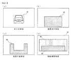
図5は、HUD45の表示領域を説明するための図である。
ナビゲーション装置1は、HUD45による表示画面を前方車領域81、重畳案内領域82、視線履歴高領域83、視線履歴中領域84、視線履歴低領域85に区分する。
なお、HUD45の表示領域は、運転者が運転操作にともなって視認する情景と重なっており、運転者の視界に対応している。FIG. 5 is a diagram for explaining the display area of the
The
Note that the display area of the
前方車領域81は、画像認識された前方車両が占める領域である。前方車領域81に案内情報を表示すると、例えば、前方車両のブレーキランプの視認性が低下するなど、運転者の運転操作に影響する可能性がある。
そのため、ナビゲーション装置1では、運転者の視認性を確保する必要がある対象の占める領域を表示禁止領域としてまずHUD45上に確保する。The
Therefore, in the
重畳案内領域82は、原則的に案内情報を表示する領域である。
重畳案内領域82は、例えば、交差点の右左折案内が交差点と重なって表示されるなど、運転者の視界において案内情報が案内対象と重畳して表示される位置に設定されている。The
The
視線履歴高領域83、視線履歴中領域84、視線履歴低領域85は、それぞれ、運転者の視線の頻度が高い領域、中程度の領域、低い領域である。
視線履歴高領域83、視線履歴中領域84、視線履歴低領域85は、走行場面に従って、視線履歴DB57から動的に生成される。
なお、本実施形態では、視線履歴低領域85は、全表示領域から視線履歴高領域83と視線履歴中領域84を除いたものとなっている。
また、図5では、各領域が分かり易いように斜線を付すなどして図示してあるが、HUD45には表示されず、運転者には視認されない。The line-of-sight history
The line-of-sight history
In this embodiment, the line-of-sight history
Further, in FIG. 5, each region is illustrated with hatching so as to be easily understood, but is not displayed on the
図6は、各表示領域を詳細に説明するための図である。
図6(a)に示したように、前方車領域81は、前方車両を矩形に囲んだ領域である。図では、1台であるが、前方に複数の車両が存在する場合は、それぞれの車両ごとに前方車領域81が生成される。FIG. 6 is a diagram for explaining each display area in detail.
As shown in FIG. 6A, the
ここで、車両は、前記運転者の視界に存在する特定対象として機能しており、ナビゲーション装置1は、前記運転者の視界に存在する特定対象を検知する検知手段を備えている。
本実施形態では、案内情報を重畳しない対象(特定対象)として前方車両を例に説明するが、その他、例えば、信号機の表示板、電光掲示板なども案内情報を重畳しない対象として考えられる。
また、前方車領域81は、検知した特定対象が前記視界において占める特定対象領域として機能しており、このため、ナビゲーション装置1は、特定対象領域を設定する設定手段を備えている。Here, the vehicle functions as a specific target existing in the driver's field of vision, and the
In the present embodiment, a front vehicle is described as an example of a target (specific target) on which guidance information is not superimposed. For example, a display board of a traffic light, an electric bulletin board, and the like are also considered as targets on which guidance information is not superimposed.
Further, the
図6(b)に示したように、重畳案内領域82は、運転者の頭部の正面付近に設定される。これは、重畳案内領域82に案内情報を表示すると案内対象と案内情報が重なって(重畳して)表示されるようにするためである。案内対象と案内情報が重なると、運転者の視線移動を著しく少なくすることができる。
このように、表示領域は、運転者の視界において、案内対象と重なる領域に設定されている。As shown in FIG. 6B, the overlapping
Thus, the display area is set to an area overlapping with the guidance target in the driver's field of view.
本実施形態では、案内情報がより案内対象と重なるように、案内種別に応じて、右左折系用、注意喚起系用、及び運転支援系用の重畳案内領域82を用意してある。
これは、例えば、レーンリスト(運転支援系)は、交差点(右左折系)よりも手前に位置するなど、案内対象と重畳する位置が案内種別によって異なるためである。
なお、これは、一例であって、より細かく案内情報ごとに重畳案内領域82を設定してもよい。In the present embodiment, a
This is because, for example, the lane list (driving support system) is positioned in front of the intersection (right / left turn system), and the position superimposed on the guidance target differs depending on the guidance type.
This is an example, and the
また、運転者の視界は、座高などにより個人差があるが、個人差を考慮しても案内情報が案内対象と重畳して表示される位置は、あまり変わらないため、重畳案内領域82の位置は、全ての運転者に対して一律に設定されている。
更に、視線カメラ32で運転者の眼部を検出し、眼部の位置に応じて調整したり、視線履歴を用いて調整したりなど、個人ごとに重畳案内領域82の位置を調整してもよい。Further, although the driver's field of view varies depending on the seating height and the like, the position where the guidance information is superimposed and displayed on the guidance object does not change much even considering the individual difference. Is set uniformly for all drivers.
Furthermore, even if the position of the
なお、次に説明するが、重畳案内領域82から前方車領域81を除いた領域を重畳可能領域と呼ぶ。
重畳案内領域82は、車両の運転者の視界において、特定した案内情報に対して予め設定された表示領域として機能しており、このため、ナビゲーション装置1は、表示領域取得手段を備えている。In addition, although demonstrated below, the area | region remove | excluding the front vehicle area |
The
なお、図では、画面の中央付近に重畳案内領域82が描かれているが、右ハンドルの場合は右寄りに、左ハンドルの場合は左寄りに設定するなど、案内対象と案内情報が重畳し易い位置に設定されている。 In the figure, a
図6(c)は、重畳可能領域86を示した図である。重畳可能領域86は、重畳案内領域82から、前方車領域81と重なっている部分を除いた領域である。
重畳案内領域82は、原則として案内情報を表示する領域であるが、重畳案内領域82と前方車領域81が重なっていると、当該重なっている部分には案内情報が表示できない。
そこで、重畳可能領域86は、重畳案内領域82に前方車領域81が重なっている場合に案内情報を表示できる領域である。
このように、ナビゲーション装置1は、表示領域のうち、設定した特定対象領域と重ならない領域に案内情報を表示する表示手段を備えている。FIG. 6C shows the
The
Therefore, the
As described above, the
本実施形態では、重畳可能領域86の面積が重畳案内領域82の面積の50%以上の場合は、簡易的な案内情報を重畳可能領域86に表示し、50%未満の場合は、視線履歴高領域83〜視線履歴低領域85に表示する。
このように、ナビゲーション装置1は、案内対象に案内情報を重畳するのが困難な場合でも、なるべく運転者の視線の移動が少なくなる領域に案内情報を表示する。
以上のように、ナビゲーション装置1は、表示領域(重畳案内領域82)のうち、特定対象領域(前方車領域81)と重ならない領域の面積が所定の規定値を下回る場合、取得した表示領域、及び設定した特定対象領域の領域外に前記案内情報を表示する。In the present embodiment, when the area of the
Thus, even when it is difficult to superimpose the guidance information on the guidance target, the
As described above, when the area of a region that does not overlap the specific target region (the front vehicle region 81) in the display region (superimposed guidance region 82) falls below a predetermined specified value, the
図6(d)は、視線履歴高領域83、視線履歴中領域84、視線履歴低領域85を示した図である。
この例では、視線履歴高領域83は、矩形に設定されており、視線履歴中領域84は、より大きな矩形領域から視線履歴高領域83を除いた領域である。
更に、視線履歴低領域85は、画面全体から視線履歴高領域83と視線履歴中領域84を除いた領域である。これらの領域は、視線履歴DB57を用いて設定される。
ここで、視線履歴高領域83〜視線履歴低領域85は、運転者の視界に対応しており、そのため、ナビゲーション装置1は、記憶した視線の履歴を用いて、視界を、視線の頻度によって複数の視線領域に区分する区分手段を備えている。FIG. 6D is a diagram showing a line-of-sight history
In this example, the line-of-sight history
Further, the line-of-sight history
Here, the line-of-sight history
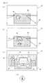
図7は、交差点(右左折系)での案内情報の表示を説明するための図である。
図7(a)は、重畳案内領域82に前方車領域81が存在しない場合を示している。この場合、重畳案内領域82の全域を案内情報の表示に使用することができる。
そのため、ナビゲーション装置1は、案内情報(この場合、交差点を右折)から重畳案内図91を生成し、道路101に重畳して表示する。重畳案内図91は、道路101に重なっているため、運転者は、視線の移動を極小にして案内情報を視認することができる。FIG. 7 is a diagram for explaining display of guidance information at an intersection (right-left turn system).
FIG. 7A shows a case where the
Therefore, the
図7(b)は、重畳案内領域82において前方車領域81の占める割合が面積比で50%未満の場合を示している。
この場合、ナビゲーション装置1は、案内可能領域、即ち、重畳案内領域82から前方車領域81を除いた領域に案内情報から生成した簡易重畳案内図92を表示する。
簡易重畳案内図92は、案内対象(この場合、交差点)と、完全には重ならないが、重畳案内領域82に表示されているため、一部重なり、運転者の視線の移動を最小限にすることができる。FIG. 7B shows a case where the ratio of the
In this case, the
The simplified
簡易重畳案内図92は、重畳案内図91を簡易化したものであり、重畳案内図91より小さい図柄で表示スペースを省略している。
そして、簡易重畳案内図92は、情報の欠落を防ぐため、「30m」などと、文字情報により画像情報を補填している。
なお、重畳案内図91の場合は、案内対象と重なっているため、「30m」などの文字を表示せずとも運転者に案内情報が不足なく伝達される。The simplified superimposition guide diagram 92 is a simplification of the superimposition guide diagram 91, and a display space is omitted with a symbol smaller than the superimposition guide diagram 91.
In the simplified superimposition guide diagram 92, image information is supplemented with character information such as “30 m” in order to prevent missing information.
In the case of the superimposed guidance diagram 91, since it overlaps with the guidance target, the guidance information is transmitted to the driver without a shortage without displaying characters such as “30 m”.
図7(c)は、重畳案内領域82において前方車領域81の占める割合が面積比で50%以上の場合を示している。
この場合、ナビゲーション装置1は、簡易重畳案内図92に案内情報を表示することはせず、視線履歴高領域83〜視線履歴低領域85に案内情報を表示する。FIG. 7C shows a case where the ratio of the
In this case, the
交差点における右左折系の案内情報は、視線履歴頻度判定表58(図3)において、視線履歴頻度が「高」に設定されているため、ナビゲーション装置1は、表示領域として視線履歴高領域83を選択し、視線履歴高領域83から前方車領域81と重畳案内領域82を除いた領域に簡易案内図93を表示する。 Since the gaze history frequency is set to “high” in the gaze history frequency determination table 58 (FIG. 3), the
簡易案内図93は、簡易重畳案内図92をよりコンパクトにアイコン化したものである。簡易案内図93も「30m」などと文字情報で情報を補うことにより、案内情報の欠落を防いでいる。
簡易案内図93は、案内対象と重ならないものの、視線履歴高領域83に表示されるため、運転者の視線の移動を少なくすることができる。
更に、ナビゲーション装置1は、簡易案内図93を、右折の場合は、右側に表示し、左折の場合は左側に表示するなどし、運転者の視線の移動を最小限にする。The simplified guide diagram 93 is a more compact iconized version of the simplified superimposition guide diagram 92. The
Although the
Further, the
このように、ナビゲーション装置1は、重畳案内領域82の外に案内情報を表示する場合、視線履歴高領域83〜視線履歴低領域85に表示するため、領域外に案内情報を表示する場合、所定の視線領域に表示している。
また、ナビゲーション装置1は、重畳案内図91、簡易重畳案内図92、簡易案内図93と表示領域によって表示形態を変化させるため、案内情報を表示する領域に応じて当該案内情報の表示画像を変化させている。As described above, the
In addition, the
ナビゲーション装置1は、視線履歴高領域83に他の前方車両による前方車領域81があるなど、視線履歴高領域83に十分な表示領域がない場合は、視線履歴頻度を1つ下げ、視線履歴中領域84で表示領域を探索し、視線履歴中領域84でも十分な表示領域がない場合は、視線履歴低領域85に簡易案内図93を表示する。
このように、ナビゲーション装置1は、所定の視線領域の面積が前記案内情報を表示するための所定の面積を満たさない場合、より頻度の低い視線領域に前記案内情報を表示する。When there is not a sufficient display area in the line-of-sight history
As described above, the
図8は、分岐点(右左折系)での案内情報の表示を説明するための図である。
図8(a)は、重畳案内領域82に前方車領域81が存在しない場合を示している。
この場合、ナビゲーション装置1は、重畳案内領域82の全域を用いることができ、道路101に重畳して重畳案内図91(この場合、左側の分岐を選択する案内情報)を表示する。
図8(b)は、重畳案内領域82において前方車領域81の占める割合が面積比で50%未満の場合を示している。
この場合、ナビゲーション装置1は、重畳可能領域に簡易重畳案内図92を表示する。FIG. 8 is a diagram for explaining the display of guidance information at a branch point (right-left turn system).
FIG. 8A shows a case where the
In this case, the
FIG. 8B shows a case where the ratio of the
In this case, the
図8(c)は、重畳案内領域82において前方車領域81の占める割合が面積比で50%以上の場合を示している。
分岐は、視線履歴頻度が「高」に設定されているため、ナビゲーション装置1は、表示領域として視線履歴高領域83を選択し、視線履歴高領域83から前方車領域81と重畳案内領域82を除いた領域に簡易案内図93を表示する。
視線履歴高領域83に、十分な表示領域がない場合、ナビゲーション装置1は、視線履歴中領域84、視線履歴低領域85の順に、表示スペースを探索する。FIG. 8C shows a case where the proportion of the
Since the line-of-sight history frequency is set to “high” for the branch, the
When the line-of-sight history
図9は、進入禁止(注意喚起系)の案内情報の表示を説明するための図である。
図9(a)は、重畳案内領域82に前方車領域81が存在しない場合を示している。
この場合、ナビゲーション装置1は、重畳案内領域82の全域を用いることができ、道路101に重畳して重畳案内図91(この場合、左側進入禁止を意味する案内情報)を表示する。
図9(b)は、重畳案内領域82において前方車領域81の占める割合が面積比で50%未満の場合を示している。
この場合、ナビゲーション装置1は、重畳可能領域に簡易重畳案内図92を表示する。FIG. 9 is a diagram for explaining the display of guidance information for entry prohibition (attention alerting system).
FIG. 9A shows a case where the
In this case, the
FIG. 9B shows a case where the ratio of the
In this case, the
図9(c)は、重畳案内領域82において前方車領域81の占める割合が面積比で50%以上の場合を示している。
進入禁止は、視線履歴頻度が「中」に設定されているため、ナビゲーション装置1は、表示領域として視線履歴中領域84を選択し、視線履歴中領域84から前方車領域81と重畳案内領域82を除いた領域に簡易案内図93を表示する。
視線履歴高領域83に、十分な表示領域がない場合、ナビゲーション装置1は、視線頻度を1つ下げ、視線履歴低領域85に簡易案内図93を表示する。
図9(d)に示した合流注意(注意喚起系)も進入禁止と同様に表示される。FIG. 9C shows a case where the proportion of the
In the entry prohibition, since the line-of-sight history frequency is set to “medium”, the
When there is not a sufficient display area in the line-of-sight history
The merging notice (attention calling system) shown in FIG. 9D is also displayed in the same manner as the entry prohibition.
図10は、レーンリスト案内(運転支援系)の案内情報の表示を説明するための図である。
図10(a)は、重畳案内領域82に前方車領域81が存在しない場合を示している。
この場合、ナビゲーション装置1は、重畳案内領域82の全域を用いることができ、道路101のレーンに重畳して重畳案内図91、91(この場合、左側レーンは直進、右側レーンは直進と右折を意味する案内情報)を表示する。FIG. 10 is a diagram for explaining display of guidance information for lane list guidance (driving support system).
FIG. 10A shows a case where the
In this case, the
図10(b)は、重畳案内領域82において前方車領域81の占める割合が面積比で0%よりも大きい場合、即ち、重畳案内領域82に前方車領域81が少しでも重なった場合を示している。
レーン案内は、視線履歴頻度が「低」に設定されている。この場合、ナビゲーション装置1は、重畳案内領域82に前方車領域81が重なると、表示領域として視線履歴低領域85を選択し、視線履歴低領域85から前方車領域81と重畳案内領域82を除いた領域に簡易案内図93を表示する。
このように、ナビゲーション装置1は、重畳案内領域82に前方車領域81が重なると、その面積比にかかわらず、視線履歴低領域85に簡易案内図93を表示する。これは、運転支援系の案内情報は、緊急度が低いため、重畳可能領域86に表示するほどの重要性がないからである。FIG. 10B shows a case where the ratio of the
In the lane guidance, the line-of-sight history frequency is set to “low”. In this case, the
As described above, when the
図11は、看板案内(運転支援系)の案内情報の表示を説明するための図である。
図11(a)は、重畳案内領域82に前方車領域81が存在しない場合を示している。
この場合、ナビゲーション装置1は、重畳案内領域82の全域を用いることができ、道路101に重畳して重畳案内図91(この場合、行き先案内を意味する案内情報)を表示する。FIG. 11 is a diagram for explaining display of guidance information for signboard guidance (driving support system).
FIG. 11A shows a case where the
In this case, the
図11(b)は、重畳案内領域82において前方車領域81の占める割合が面積比で0%よりも大きい場合を示している。
看板案内は、視線履歴頻度が「低」に設定されている。この場合、ナビゲーション装置1は、重畳案内領域82に前方車領域81が重なると、表示領域として視線履歴低領域85を選択し、視線履歴低領域85から前方車領域81と重畳案内領域82を除いた領域に簡易案内図93を表示する。FIG. 11B shows a case where the ratio of the
In the signage guidance, the line-of-sight history frequency is set to “low”. In this case, the
次に、以上のように構成されたナビゲーション装置1の動作について説明する。
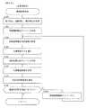
図12は、HUD45の表示を用いた案内処理の全体を説明するためのフローチャートである。
以下の処理は、情報処理装置20(図2)のCPU21がナビゲーションプログラム51を実行することにより行われる。Next, the operation of the
FIG. 12 is a flowchart for explaining the entire guidance process using the display of the
The following processing is performed by the
ナビゲーション装置1は、ナビゲーション機能部68により現在位置と進行方向を検出し、前方に右左折系の案内対象があるか否かを判断する(ステップ5)。
前方に右左折系の案内対象がない場合(ステップ5;N)、ナビゲーション装置1は、ステップ5で引き続き右左折系の案内対象の有無を監視する。
一方、前方に右左折系の案内対象があった場合(ステップ5;Y)、ナビゲーション装置1は、右左折系案内処理を行う(ステップ15)。The
If there is no right-left turn guidance object ahead (
On the other hand, when there is a left / right turn guidance object ahead (
また、ナビゲーション装置1は、ステップ5、15を行いながら、同時に前方に注意喚起系の案内対象があるか否かを判断する(ステップ20)。
前方に注意喚起系の案内対象がない場合(ステップ20;N)、ナビゲーション装置1は、ステップ20で引き続き注意喚起系の案内対象の有無を監視する。
一方、前方に注意喚起系の案内対象があった場合(ステップ20;Y)、ナビゲーション装置1は、注意喚起系案内処理を行う(ステップ25)。In addition, the
When there is no attention-guided guidance target ahead (step 20; N), the
On the other hand, when there is a guidance object of the attention system ahead (step 20; Y), the
更に、ナビゲーション装置1は、ステップ5、15、20、25を行いながら、同時に前方に運転支援系の案内対象があるか否かを判断する(ステップ30)。
前方に運転支援系の案内対象がない場合(ステップ30;N)、ナビゲーション装置1は、ステップ30で引き続き運転支援系の案内対象の有無を監視する。
一方、前方に運転支援系の案内対象があった場合(ステップ30;Y)、ナビゲーション装置1は、運転支援系案内処理を行う(ステップ35)。Further, the
When there is no driving support system guidance target ahead (step 30; N), the
On the other hand, when there is a driving assistance system guidance target ahead (step 30; Y), the
このように、ナビゲーション装置1は、右左折系案内処理、注意喚起系案内処理、及び、運転支援系案内処理を同時に並行して行うため、HUD45に、例えば、右左折系の交差点案内と運転支援系の看板案内が同時に表示される場合がある。
ナビゲーション装置1は、重畳案内領域82に案内情報2つ分の表示スペースが確保できる場合、交差点案内と看板案内を共に重畳案内領域82に表示し、表示スペースが確保できない場合、緊急度の低い看板案内を視線履歴頻度判定表58に従って視線履歴低領域85に表示する。
このように、ナビゲーション装置1は、複数の案内情報を表示する際に、緊急度の高いものほど運転者の視線移動が少ない領域(目に付き易い領域)に表示することができる。As described above, the
The
Thus, when displaying a plurality of guidance information, the
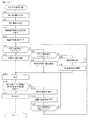
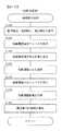
図13は、右左折系案内処理の手順を説明するためのフローチャートである。
ナビゲーション装置1は、前方車領域81を画像認識により検知する(ステップ50)。
次に、ナビゲーション装置1は、当該案内対象に対する案内情報(ここでは、右折か左折かを表す右左折情報)を取得する(ステップ55)。
次に、ナビゲーション装置1は、右左折系用の重畳案内領域82をHUD45の画面上に確保する(ステップ60)。FIG. 13 is a flowchart for explaining the procedure of the left / right turn type guidance processing.
The
Next, the
Next, the
次に、ナビゲーション装置1は、重畳可能領域86を計算し(ステップ65)、重畳可能領域86の重畳案内領域82に対する面積比が100%か否かを判断する(ステップ70)。
重畳可能領域86の重畳案内領域82に対する面積比が100%の場合(即ち、重畳案内領域82に前方車領域81が存在しない場合)(ステップ70;Y)、ナビゲーション装置1は、重畳案内図91を描画して(ステップ75)、重畳可能領域86に表示する(ステップ100)。Next, the
When the area ratio of the
一方、重畳可能領域86の重畳案内領域82に対する面積比が100%でない場合(即ち、重畳案内領域82に前方車領域81が存在する場合)(ステップ70;N)、ナビゲーション装置1は、重畳可能領域86の重畳案内領域82に対する面積比が50%以上か否かを判断する(ステップ80)。 On the other hand, when the area ratio of the
重畳可能領域86の重畳案内領域82に対する面積比が50%以上の場合(ステップ80;Y)、ナビゲーション装置1は、簡易重畳案内図92を描画して(ステップ85)、重畳可能領域86に表示する(ステップ100)。
一方、重畳可能領域86の重畳案内領域82に対する面積比が50%未満の場合(ステップ80;N)、ナビゲーション装置1は、簡易案内図93を表示する領域を探索する領域探索処理を行う(ステップ90)。
そして、ナビゲーション装置1は、簡易案内図93を描画し(ステップ95)、領域探索処理で探索された視線履歴高領域83〜視線履歴低領域85の何れかに簡易案内図93を表示する(ステップ100)。When the area ratio of the
On the other hand, when the area ratio of the
Then, the
ナビゲーション装置1は、案内情報をHUD45に表示した後(ステップ100)、ナビゲーションにより、案内対象までの距離が案内図変更可能距離未満か否かを判断する(ステップ105)。
案内図変更可能距離とは、重畳案内図91などの案内情報の表示を更新できる距離であり、案内対象から現在位置までの距離が案内図変更可能距離以上である場合、ナビゲーション装置1は、案内情報の表示形態(重畳案内図91、簡易重畳案内図92、簡易案内図93)を更新することができる。After displaying the guidance information on the HUD 45 (step 100), the
The guide map changeable distance is a distance at which the display of guide information such as the
案内対象までの距離が案内図変更可能距離未満である場合(ステップ105;Y)、ナビゲーション装置1は、案内を終了し(ステップ110)、案内処理のメインルーチンにリターンする。
一方、案内対象までの距離が案内図変更可能距離以上である場合(ステップ105;N)、ナビゲーション装置1は、前方車領域81を検知し(ステップ115)、重畳可能領域86を計算する(ステップ120)。なお、重畳可能領域86の計算には、重畳案内領域82の確保が必要であるが、これは、ステップ60で確保したものを使用する。When the distance to the guidance target is less than the guide map changeable distance (
On the other hand, when the distance to the guidance object is equal to or greater than the guide map changeable distance (
そして、ナビゲーション装置1は、現在表示に使用している重畳可能領域86と比較して新たに検知した重畳可能領域86が変化したか否か(即ち、100%、50%以上、50%未満の状態が変化したか否か)を判断する(ステップ125)。
ナビゲーション装置1は、重畳可能領域86が変化しない場合(ステップ125;N)、ステップ100に戻って現在の表示を継続し、変化した場合(ステップ125;Y)、ステップ70に戻って表示を更新する。Then, the
When the
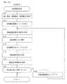
図14は、ステップ90の領域探索処理を説明するためのフローチャートである。
ナビゲーション装置1は、ナビゲーション機能部68より案内種別(右左折系、注意喚起系、運転支援系)、道路種別(高速道路、一般道、細街路)、場所種別(市街、郊外)を取得して(ステップ150)、現在の走行場面を特定する。FIG. 14 is a flowchart for explaining the area search processing in step 90.
The
次に、ナビゲーション装置1は、取得した案内種別を視線履歴頻度判定表58(図3(b))に適用して視線履歴頻度のレベル(高・中・低)を判定する(ステップ155)。
そして、ナビゲーション装置1は、判定結果をRAM24の記憶領域に一時記憶し、以下の処理で使用するレベルに設定する(ステップ160)。この例は、右左折系のため、視線履歴頻度として「高」を設定する。なお、この設定値は、ステップ185のループ処理を経るたびに「中」、「低」と書き換えられる。Next, the
Then, the
次に、ナビゲーション装置1は、道路種別と場所種別に基づいて、これに適合する視線履歴DBa〜視線履歴DBeを選択する(ステップ165)。
次に、ナビゲーション装置1は、ステップ160でRAM24に記憶した判定結果を参照することにより、使用する視線履歴DBのレベルを判定する(ステップ170)。
例えば、ステップ165で視線履歴DBaを選択した場合、ステップ160で一時記憶した判定結果が「高」であるため、視線履歴DBa(高)が使用するデータベースとなる。Next, based on the road type and the location type, the
Next, the
For example, when the line-of-sight history DBa is selected in
次に、ナビゲーション装置1は、ステップ170で判定した視線履歴DBを用いて視線履歴領域をHUD45の画面上に取得する(ステップ175)。
例えば、視線履歴DB(高)を用いた場合、当該データベースによる視線履歴高領域83を取得する。
次に、ナビゲーション装置1は、取得した視線履歴領域(例えば、視線履歴高領域83)から、簡易案内図領域(前方車領域81と重畳案内領域82を除いた領域)を確保する(ステップ180)。Next, the
For example, when the line-of-sight history DB (high) is used, the line-of-sight history
Next, the
次に、ナビゲーション装置1は、簡易案内図領域に簡易案内図93を描画できるか否か(即ち、描画スペースがあるか否か)を判断する(ステップ185)。
描画できる場合(ステップ185;Y)、ナビゲーション装置1は、右左折系案内処理ルーチンにリターンし、描画できない場合(ステップ185;N)、ナビゲーション装置1は、視線履歴頻度を1つ下げ(ステップ190)、ステップ160に戻る。
この例では、視線履歴頻度が「高」だったのがステップ190で「中」になり、ステップ160に戻って、視線履歴頻度の判定結果としてRAM24に「中」が設定される。
以下、ナビゲーション装置1は、同様の処理を繰り返す。ただし、視線履歴頻度の判定結果が「低」の場合、視線履歴頻度をこれ以上下げられないため、この場合は、ステップ185を行わず、右左折案内処理ルーチンにリターンする。Next, the
If drawing is possible (step 185; Y), the
In this example, the line-of-sight history frequency was “high”, which becomes “medium” in step 190, the process returns to step 160, and “medium” is set in the
Thereafter, the
図15は、注意喚起系案内処理の手順を説明するためのフローチャートである。
図13の右左折系案内処理に対応するステップには、図13のステップ番号に200を加えたステップ番号を付し、説明を簡略化、又は省略する。
ナビゲーション装置1は、前方車領域81を検知した後(ステップ250)、当該案内対象に対する案内情報(ここでは、注意喚起系の案内)を取得する(ステップ255)。
次に、ナビゲーション装置1は、注意喚起系用の重畳案内領域82をHUD45の画面上に確保する(ステップ260)。
以下、ステップ265〜325では、図13の対応するステップ65〜125と同様の処理を行う。FIG. 15 is a flowchart for explaining the procedure of the alerting guidance process.
Steps corresponding to the right / left turn guidance processing in FIG. 13 are given step numbers obtained by adding 200 to the step numbers in FIG. 13, and description thereof will be simplified or omitted.
After detecting the forward vehicle area 81 (step 250), the
Next, the
Thereafter, in
図16は、ステップ290の領域探索処理を説明するためのフローチャートである。
図14の領域探索処理に対応するステップには、図14のステップ番号に200を加えたステップ番号を付し、説明を簡略化、又は省略する。
ナビゲーション装置1は、ナビゲーション機能部68より案内種別、道路種別、場所種別を取得する(ステップ350)。
次に、ナビゲーション装置1は、案内種別を視線履歴頻度判定表58に適用して視線履歴頻度のレベル(高・中・低)を判定し(ステップ355)、判定結果をRAM24に設定する(ステップ360)。この例は、注意喚起系のため、視線履歴頻度として「中」を設定する。FIG. 16 is a flowchart for explaining the region search processing in step 290.
Steps corresponding to the region search processing of FIG. 14 are given step numbers obtained by adding 200 to the step numbers of FIG. 14, and the description will be simplified or omitted.
The
Next, the
次に、ナビゲーション装置1は、道路種別と場所種別に適合する視線履歴DBa〜視線履歴DBeの何れかを選択し(ステップ365)、視線履歴領域の設定に使用する視線履歴DBのレベルを判定する(ステップ370)。ここでは、「中」と判定する。 Next, the
次に、ナビゲーション装置1は、ステップ370で判定した視線履歴DBを用いて視線履歴領域をHUD45の画面上に取得する(ステップ375)。この例は、注意喚起系のため、視線履歴中領域84を取得する。
次に、ナビゲーション装置1は、視線履歴中領域84から、簡易案内図領域を確保する(ステップ380)。Next, the
Next, the
次に、ナビゲーション装置1は、簡易案内図領域に簡易案内図93を描画できるか否かを判断する(ステップ385)。
描画できる場合(ステップ385;Y)、ナビゲーション装置1は、注意喚起系案内処理ルーチンにリターンし、描画できない場合(ステップ385;N)、ナビゲーション装置1は、RAM24に記憶した視線履歴頻度を1つ下げて「低」とし(ステップ390)、ステップ160に戻る。Next, the
If drawing is possible (step 385; Y), the
図17は、運転支援系案内処理の手順を説明するためのフローチャートである。
図13の右左折系案内処理に対応するステップには、図13のステップ番号に400を加えたステップ番号を付し、説明を簡略化、又は省略する。
ナビゲーション装置1は、前方車領域81を検知した後(ステップ450)、当該案内対象に対する案内情報(ここでは、運転支援系の案内)を取得する(ステップ455)。
次に、ナビゲーション装置1は、運転支援系用の重畳案内領域82をHUD45の画面上に確保する(ステップ460)。
次に、ナビゲーション装置1は、重畳可能領域86を計算し(ステップ465)、重畳可能領域86の重畳案内領域82に対する面積比が100%か否かを判断する(ステップ470)。
重畳可能領域86の重畳案内領域82に対する面積比が100%の場合(即ち、重畳案内領域82に前方車領域81が存在しない場合)(ステップ470;Y)、ナビゲーション装置1は、重畳案内図91を描画して(ステップ475)、重畳可能領域86に表示する(ステップ500)。FIG. 17 is a flowchart for explaining the procedure of the driving assistance system guidance process.
Steps corresponding to the right / left turn guidance process in FIG. 13 are given step numbers obtained by adding 400 to the step numbers in FIG. 13, and the description will be simplified or omitted.
After detecting the front vehicle area 81 (step 450), the
Next, the
Next, the
When the area ratio of the
一方、重畳可能領域86の重畳案内領域82に対する面積比が100%でない場合(ステップ470;N)、ナビゲーション装置1は、簡易案内図93を表示する領域を探索する領域探索処理を行う(ステップ490)。
以下、ステップ495〜525は、図13のステップ95〜125と同様である。
このように、運転支援系では、ナビゲーション装置1は、重畳可能領域86が100%でない場合、簡易重畳案内図92の描画は行わず、簡易案内図93を描画する。On the other hand, when the area ratio of the
Hereinafter, steps 495 to 525 are the same as
Thus, in the driving support system, when the
図18は、ステップ490の領域探索処理を説明するためのフローチャートである。
図14の領域探索処理に対応するステップには、図14のステップ番号に400を加えたステップ番号を付し、説明を簡略化、又は省略する。
ナビゲーション装置1は、ナビゲーション機能部68より案内種別、道路種別、場所種別を取得する(ステップ550)。
次に、ナビゲーション装置1は、案内種別を視線履歴頻度判定表58に適用して視線履歴頻度のレベル(高・中・低)を判定し(ステップ555)、判定結果をRAM24に設定する(ステップ560)。この例は、運転支援系のため、視線履歴頻度として「低」を設定する。FIG. 18 is a flowchart for explaining the region search processing in
Steps corresponding to the region search processing in FIG. 14 are given step numbers obtained by adding 400 to the step numbers in FIG. 14, and description thereof will be simplified or omitted.
The
Next, the
次に、ナビゲーション装置1は、道路種別と場所種別に基づいて視線履歴DBa〜視線履歴DBeを選択し(ステップ565)、視線履歴領域の設定に使用する視線履歴DBのレベルを判定する(ステップ570)。この例では、運転支援系のため、「低」と判定する。 Next, the
次に、ナビゲーション装置1は、ステップ570で判定した視線履歴DBを用いて視線履歴領域をHUD45の画面上に取得する(ステップ575)。この例は、運転支援系のため、視線履歴低領域85を取得する。
次に、ナビゲーション装置1は、視線履歴低領域85において、簡易案内図領域を確保し(ステップ580)、運転支援系案内処理ルーチンにリターンする。
運転支援系では、視線履歴低領域85に案内情報を表示するため、視線履歴頻度を1つ下げるステップはない。Next, the
Next, the
In the driving support system, since the guide information is displayed in the line-of-sight history
以上に説明した実施形態により、次のような効果を得ることができる。
(1)重畳案内領域82は、運転者の視界において案内対象と重畳する位置に設定されている。そのため、案内対象と重畳して案内情報(重畳案内図91)を表示することができ、案内情報の視認に要する運転者の視線の移動を低減することができる。
(2)運転者の視界に車両などの案内情報の重畳表示を避ける特定対象が存在する場合に、運転者の視界における特定対象の領域を除いて案内情報を表示することができる。
(3)運転者の視線を認識するデバイスを用いることで運転者の視線を考慮した領域に案内情報を表示することができ、ユーザの視線移動による視認性の低下を抑制することができる。
(4)案内情報表示の優先度と視線の領域頻度の組み合わせにより、優先度の高い案内情報を、運転者の視線の頻度が高い領域に表示し、優先度の低い案内情報を、運転者の視線の頻度が低い領域に表示することができる。
(5)予め地点ごとのユーザ視線分布を蓄積し、それを一定の閾値ごとの視線履歴領域に分けることができ、視線履歴領域と重畳案内領域の差分、又は、重畳案内領域に案内情報を表示することができる。According to the embodiment described above, the following effects can be obtained.
(1) The
(2) When there is a specific target in the driver's field of view that avoids superimposed display of guidance information such as a vehicle, the guide information can be displayed excluding the region of the specific target in the driver's field of view.
(3) By using a device for recognizing the driver's line of sight, guidance information can be displayed in a region in which the driver's line of sight is taken into account, and a reduction in visibility due to the movement of the user's line of sight can be suppressed.
(4) By combining the priority of the guidance information display and the area frequency of the line of sight, the high-priority guidance information is displayed in the area where the driver's line-of-sight is high, and the low-priority guidance information is displayed It is possible to display in an area where the line-of-sight frequency is low.
(5) The user gaze distribution for each point can be stored in advance, and the user gaze distribution can be divided into gaze history areas for each fixed threshold, and the guidance information is displayed in the difference between the gaze history area and the superimposed guidance area or in the superimposed guidance area can do.
1 ナビゲーション装置
10 現在位置検出装置
12 方位センサ
13 距離センサ
14 GPS受信装置
15 地磁気センサ
20 情報処理装置
28 クロック
30 撮影装置
31 フロントカメラ
32 視線カメラ
40 入出力装置
41 入力装置
42 ディスプレイ
44 スピーカ
45 HUD
46 マイクロフォン
50 記憶装置
51 ナビゲーションプログラム
52 地図DB
54 案内情報DB
55 交通情報DB
56 画像認識用DB
57 視線履歴DB
58 視線履歴頻度判定表
60 画像認識機能部
61 撮影部
62 画像処理認識部
63 視線認識機能部
64 視線管理部
65 視線情報サービス部
66 音声認識機能部
67 音声認識部
68 ナビゲーション機能部
69 案内処理部
71 各センサ
73 音声制御部
81 前方車領域
82 重畳案内領域
83 視線履歴高領域
84 視線履歴中領域
85 視線履歴低領域
86 重畳可能領域
91 重畳案内図
92 簡易重畳案内図
93 簡易案内図
101 道路DESCRIPTION OF
46 Microphone 50 Storage device 51 Navigation program 52 Map DB
54 Guidance Information DB
55 Traffic Information DB
56 Image recognition database
57 Gaze History DB
58 Gaze History Frequency Determination Table 60 Image
Claims (8)
Translated fromJapanese前記特定した案内対象の案内情報を取得する案内情報取得手段と、
前記車両の運転者の視界において、前記取得した案内情報に対して予め設定された表示領域を取得する表示領域取得手段と、
前記運転者の視界に存在する特定対象を検知する検知手段と、
前記検知した特定対象が前記視界において占める特定対象領域を設定する設定手段と、
前記取得した表示領域のうち、前記設定した特定対象領域と重ならない領域に前記取得した案内情報を表示する表示手段と、
を具備したことを特徴とする情報提供装置。A specifying means for specifying a guidance target in the forward direction of the vehicle;
Guidance information obtaining means for obtaining guidance information of the identified guidance target;
In a field of view of the driver of the vehicle, display area acquisition means for acquiring a display area set in advance for the acquired guidance information;
Detecting means for detecting a specific object existing in the driver's field of view;
Setting means for setting a specific target area occupied by the detected specific target in the field of view;
Display means for displaying the acquired guidance information in an area that does not overlap with the set specific target area among the acquired display areas;
An information providing apparatus comprising:
前記検出した視線の履歴を記憶する視線履歴記憶手段と、
前記記憶した履歴を用いて、前記視界を、視線の頻度によって複数の視線領域に区分する区分手段と、
を具備し、
前記表示手段は、前記領域外に前記案内情報を表示する場合、所定の視線領域に表示することを特徴とする請求項3に記載の情報提供装置。Gaze detection means for detecting the driver's gaze;
Line-of-sight history storage means for storing the detected line-of-sight history;
Using the stored history, the dividing means for dividing the field of view into a plurality of line-of-sight areas according to the line-of-sight frequency;
Comprising
The information providing apparatus according to claim 3, wherein the display unit displays the guidance information in a predetermined line-of-sight region when the guidance information is displayed outside the region.
前記特定した案内対象の案内情報を取得する案内情報取得機能と、
前記車両の運転者の視界において、前記取得した案内情報に対して予め設定された表示領域を取得する表示領域取得機能と、
前記運転者の視界に存在する特定対象を検知する検知機能と、
前記検知した特定対象が前記視界において占める特定対象領域を設定する設定機能と、
前記取得した表示領域のうち、前記設定した特定対象領域と重ならない領域に前記取得した案内情報を表示する表示機能と、
をコンピュータで実現する情報提供プログラム。A specific function for identifying a guidance object in the forward direction of the vehicle,
A guidance information acquisition function for acquiring the specified guidance target guidance information;
In the field of view of the driver of the vehicle, a display area acquisition function for acquiring a display area preset for the acquired guidance information;
A detection function for detecting a specific object present in the driver's field of view;
A setting function for setting a specific target area occupied by the detected specific target in the field of view;
A display function for displaying the acquired guidance information in an area that does not overlap with the set specific target area among the acquired display areas;
An information provision program that realizes a computer.
Priority Applications (1)
| Application Number | Priority Date | Filing Date | Title |
|---|---|---|---|
| JP2013054785AJP2014181927A (en) | 2013-03-18 | 2013-03-18 | Information provision device, and information provision program |
Applications Claiming Priority (1)
| Application Number | Priority Date | Filing Date | Title |
|---|---|---|---|
| JP2013054785AJP2014181927A (en) | 2013-03-18 | 2013-03-18 | Information provision device, and information provision program |
Publications (1)
| Publication Number | Publication Date |
|---|---|
| JP2014181927Atrue JP2014181927A (en) | 2014-09-29 |
Family
ID=51700790
Family Applications (1)
| Application Number | Title | Priority Date | Filing Date |
|---|---|---|---|
| JP2013054785APendingJP2014181927A (en) | 2013-03-18 | 2013-03-18 | Information provision device, and information provision program |
Country Status (1)
| Country | Link |
|---|---|
| JP (1) | JP2014181927A (en) |
Cited By (21)
| Publication number | Priority date | Publication date | Assignee | Title |
|---|---|---|---|---|
| WO2017002209A1 (en)* | 2015-06-30 | 2017-01-05 | 三菱電機株式会社 | Display control device, display control method, and display control program |
| EP3184365A3 (en)* | 2015-12-24 | 2017-07-19 | Lg Electronics Inc. | Display device for vehicle and control method thereof |
| WO2017130439A1 (en)* | 2016-01-28 | 2017-08-03 | 鴻海精密工業股▲ふん▼有限公司 | Vehicular image display system and vehicle having same image display system mounted therein |
| WO2017138297A1 (en)* | 2016-02-08 | 2017-08-17 | 株式会社リコー | Image display device and method for displaying image |
| CN107305136A (en)* | 2016-04-25 | 2017-10-31 | 现代自动车株式会社 | Guider, vehicle and the method for controlling the vehicle |
| JP2019003312A (en)* | 2017-06-13 | 2019-01-10 | 株式会社デンソーアイティーラボラトリ | Gazing object estimation device, gazing object estimation method and program |
| JP2019032243A (en)* | 2017-08-08 | 2019-02-28 | アルパイン株式会社 | Head-up display device, navigation device, and display method |
| WO2019077730A1 (en)* | 2017-10-20 | 2019-04-25 | 三菱電機株式会社 | Display control device, display control method, and display system |
| JP2019156296A (en)* | 2018-03-15 | 2019-09-19 | 矢崎総業株式会社 | Vehicular display projection device |
| JP2020153679A (en)* | 2019-03-18 | 2020-09-24 | 本田技研工業株式会社 | Notification control device and notification control method |
| US11248926B2 (en) | 2017-05-16 | 2022-02-15 | Mitsubishi Electric Corporation | Display control device and display control method |
| US11504622B1 (en) | 2021-08-17 | 2022-11-22 | BlueOwl, LLC | Systems and methods for generating virtual encounters in virtual games |
| US11593539B2 (en) | 2018-11-30 | 2023-02-28 | BlueOwl, LLC | Systems and methods for facilitating virtual vehicle operation based on real-world vehicle operation data |
| CN115824249A (en)* | 2021-09-16 | 2023-03-21 | 北京小米移动软件有限公司 | ARHUD display method, ARHUD display device and storage medium |
| US11691084B2 (en) | 2020-01-20 | 2023-07-04 | BlueOwl, LLC | Systems and methods for training and applying virtual occurrences to a virtual character using telematics data of one or more real trips |
| US11697069B1 (en) | 2021-08-17 | 2023-07-11 | BlueOwl, LLC | Systems and methods for presenting shared in-game objectives in virtual games |
| US11896903B2 (en) | 2021-08-17 | 2024-02-13 | BlueOwl, LLC | Systems and methods for generating virtual experiences for a virtual game |
| DE112018003314B4 (en)* | 2017-06-30 | 2024-02-15 | Panasonic Intellectual Property Management Co., Ltd. | Display system, information display system, method for controlling a display system, program and recording medium for a display system and mobile body |
| US11969653B2 (en) | 2021-08-17 | 2024-04-30 | BlueOwl, LLC | Systems and methods for generating virtual characters for a virtual game |
| US12001764B2 (en) | 2018-11-30 | 2024-06-04 | BlueOwl, LLC | Systems and methods for facilitating virtual vehicle operation corresponding to real-world vehicle operation |
| US12290751B2 (en) | 2021-08-17 | 2025-05-06 | Quanata, Llc | Systems and methods for generating virtual maps in virtual games |
- 2013
- 2013-03-18JPJP2013054785Apatent/JP2014181927A/enactivePending
Cited By (42)
| Publication number | Priority date | Publication date | Assignee | Title |
|---|---|---|---|---|
| DE112015006662T5 (en) | 2015-06-30 | 2018-05-03 | Mitsubishi Electric Corporation | DISPLAY CONTROL DEVICE, DISPLAY CONTROL METHOD AND DISPLAY CONTROL PROGRAM |
| JPWO2017002209A1 (en)* | 2015-06-30 | 2017-06-29 | 三菱電機株式会社 | Display control apparatus, display control method, and display control program |
| WO2017002209A1 (en)* | 2015-06-30 | 2017-01-05 | 三菱電機株式会社 | Display control device, display control method, and display control program |
| EP3184365A3 (en)* | 2015-12-24 | 2017-07-19 | Lg Electronics Inc. | Display device for vehicle and control method thereof |
| US10924679B2 (en) | 2015-12-24 | 2021-02-16 | Lg Electronics Inc. | Display device for vehicle and control method thereof |
| WO2017130439A1 (en)* | 2016-01-28 | 2017-08-03 | 鴻海精密工業股▲ふん▼有限公司 | Vehicular image display system and vehicle having same image display system mounted therein |
| CN108602465A (en)* | 2016-01-28 | 2018-09-28 | 鸿海精密工业股份有限公司 | Image display system for vehicle and vehicle equipped with the same |
| JPWO2017130439A1 (en)* | 2016-01-28 | 2018-11-08 | 鴻海精密工業股▲ふん▼有限公司 | Vehicle image display system and vehicle equipped with the image display system |
| TWI690436B (en)* | 2016-01-28 | 2020-04-11 | 鴻海精密工業股份有限公司 | Image display system for vehicle, and vehicle mounted with the image display system |
| JPWO2017138297A1 (en)* | 2016-02-08 | 2018-11-15 | 株式会社リコー | Image display apparatus and image display method |
| WO2017138297A1 (en)* | 2016-02-08 | 2017-08-17 | 株式会社リコー | Image display device and method for displaying image |
| US10890762B2 (en) | 2016-02-08 | 2021-01-12 | Ricoh Company, Ltd. | Image display apparatus and image display method |
| CN107305136A (en)* | 2016-04-25 | 2017-10-31 | 现代自动车株式会社 | Guider, vehicle and the method for controlling the vehicle |
| CN107305136B (en)* | 2016-04-25 | 2022-10-11 | 现代自动车株式会社 | Navigation device, vehicle, and method for controlling the vehicle |
| US11248926B2 (en) | 2017-05-16 | 2022-02-15 | Mitsubishi Electric Corporation | Display control device and display control method |
| JP2019003312A (en)* | 2017-06-13 | 2019-01-10 | 株式会社デンソーアイティーラボラトリ | Gazing object estimation device, gazing object estimation method and program |
| DE112018003314B4 (en)* | 2017-06-30 | 2024-02-15 | Panasonic Intellectual Property Management Co., Ltd. | Display system, information display system, method for controlling a display system, program and recording medium for a display system and mobile body |
| JP2019032243A (en)* | 2017-08-08 | 2019-02-28 | アルパイン株式会社 | Head-up display device, navigation device, and display method |
| JPWO2019077730A1 (en)* | 2017-10-20 | 2020-05-28 | 三菱電機株式会社 | Display control device, display control method, and display system |
| WO2019077730A1 (en)* | 2017-10-20 | 2019-04-25 | 三菱電機株式会社 | Display control device, display control method, and display system |
| JP7099837B2 (en) | 2018-03-15 | 2022-07-12 | 矢崎総業株式会社 | Display projection device for vehicles |
| JP2019156296A (en)* | 2018-03-15 | 2019-09-19 | 矢崎総業株式会社 | Vehicular display projection device |
| US12001764B2 (en) | 2018-11-30 | 2024-06-04 | BlueOwl, LLC | Systems and methods for facilitating virtual vehicle operation corresponding to real-world vehicle operation |
| US11593539B2 (en) | 2018-11-30 | 2023-02-28 | BlueOwl, LLC | Systems and methods for facilitating virtual vehicle operation based on real-world vehicle operation data |
| US11995384B2 (en) | 2018-11-30 | 2024-05-28 | BlueOwl, LLC | Systems and methods for facilitating virtual vehicle operation based on real-world vehicle operation data |
| JP7280072B2 (en) | 2019-03-18 | 2023-05-23 | 本田技研工業株式会社 | Notification control device and notification control method |
| JP2020153679A (en)* | 2019-03-18 | 2020-09-24 | 本田技研工業株式会社 | Notification control device and notification control method |
| US11691084B2 (en) | 2020-01-20 | 2023-07-04 | BlueOwl, LLC | Systems and methods for training and applying virtual occurrences to a virtual character using telematics data of one or more real trips |
| US12208335B2 (en) | 2020-01-20 | 2025-01-28 | Quanata, Llc | Systems and methods for training and applying virtual occurrences to a virtual character using telematics data of one or more real trips in real-time |
| US11857866B2 (en) | 2020-01-20 | 2024-01-02 | BlueOwl, LLC | Systems and methods for training and applying virtual occurrences with modifiable outcomes to a virtual character using telematics data of one or more real trips |
| US12383837B2 (en) | 2020-01-20 | 2025-08-12 | Quanata, Llc | Systems and methods for training and applying virtual occurrences and granting in-game resources to a virtual character using telematics data of one or more real trips |
| US11707683B2 (en) | 2020-01-20 | 2023-07-25 | BlueOwl, LLC | Systems and methods for training and applying virtual occurrences and granting in-game resources to a virtual character using telematics data of one or more real trips |
| US12246259B2 (en) | 2021-08-17 | 2025-03-11 | Quanata, Llc | Systems and methods for generating virtual encounters in virtual games |
| US11969653B2 (en) | 2021-08-17 | 2024-04-30 | BlueOwl, LLC | Systems and methods for generating virtual characters for a virtual game |
| US11504622B1 (en) | 2021-08-17 | 2022-11-22 | BlueOwl, LLC | Systems and methods for generating virtual encounters in virtual games |
| US11918913B2 (en) | 2021-08-17 | 2024-03-05 | BlueOwl, LLC | Systems and methods for generating virtual encounters in virtual games |
| US11697069B1 (en) | 2021-08-17 | 2023-07-11 | BlueOwl, LLC | Systems and methods for presenting shared in-game objectives in virtual games |
| US12290751B2 (en) | 2021-08-17 | 2025-05-06 | Quanata, Llc | Systems and methods for generating virtual maps in virtual games |
| US12350591B2 (en) | 2021-08-17 | 2025-07-08 | Quanata, Llc | Systems and methods for generating virtual characters for a game |
| US12370451B2 (en) | 2021-08-17 | 2025-07-29 | Quanata, Llc | Systems and methods for generating virtual experiences for a virtual game |
| US11896903B2 (en) | 2021-08-17 | 2024-02-13 | BlueOwl, LLC | Systems and methods for generating virtual experiences for a virtual game |
| CN115824249A (en)* | 2021-09-16 | 2023-03-21 | 北京小米移动软件有限公司 | ARHUD display method, ARHUD display device and storage medium |
Similar Documents
| Publication | Publication Date | Title |
|---|---|---|
| JP2014181927A (en) | Information provision device, and information provision program | |
| US11767024B2 (en) | Augmented reality method and apparatus for driving assistance | |
| US11511627B2 (en) | Display device and computer program | |
| US12151560B2 (en) | Superimposed image display device | |
| CN107848416B (en) | Display control device, display device, and display control method | |
| US9639968B2 (en) | Generating an augmented view of a location of interest | |
| JP6323074B2 (en) | Display object information display device | |
| JP2019095213A (en) | Superimposed image display device and computer program | |
| JP7476568B2 (en) | Superimposed image display device, superimposed image drawing method, and computer program | |
| JP2018173862A (en) | Driving support apparatus and computer program | |
| KR20150051671A (en) | A display control device using vehicles and user motion recognition and its method of operation | |
| US9791287B2 (en) | Drive assist system, method, and program | |
| CN113165510A (en) | Display control apparatus, method and computer program | |
| JP4277678B2 (en) | Vehicle driving support device | |
| JP6448806B2 (en) | Display control device, display device, and display control method | |
| WO2016088227A1 (en) | Video display device and method | |
| JP2014037172A (en) | Display controller and display control method for head-up display | |
| JP2015215197A (en) | Navigation device, navigation method, and navigation program | |
| JP2014174091A (en) | Information providing device and information providing program | |
| JP2014174879A (en) | Information processor and information program | |
| JP2014174880A (en) | Information processor and information program | |
| JP2019095214A (en) | Superimposed image display device and computer program | |
| JP6939147B2 (en) | Driving information guidance device and computer program | |
| JP2016161483A (en) | Information providing device and information providing program | |
| JP2019087259A (en) | Superposition image display device and computer program |