JP2014180539A - Crest-factor control of phase-shifted inverter - Google Patents
Crest-factor control of phase-shifted inverterDownload PDFInfo
- Publication number
- JP2014180539A JP2014180539AJP2014033921AJP2014033921AJP2014180539AJP 2014180539 AJP2014180539 AJP 2014180539AJP 2014033921 AJP2014033921 AJP 2014033921AJP 2014033921 AJP2014033921 AJP 2014033921AJP 2014180539 AJP2014180539 AJP 2014180539A
- Authority
- JP
- Japan
- Prior art keywords
- electrosurgical
- waveform
- inverter
- output voltage
- controller
- Prior art date
- Legal status (The legal status is an assumption and is not a legal conclusion. Google has not performed a legal analysis and makes no representation as to the accuracy of the status listed.)
- Granted
Links
- 230000007423decreaseEffects0.000claimsdescription10
- 238000000034methodMethods0.000abstractdescription28
- 230000004044responseEffects0.000description9
- 238000004804windingMethods0.000description8
- 230000015271coagulationEffects0.000description7
- 238000005345coagulationMethods0.000description7
- 238000005520cutting processMethods0.000description7
- 230000003247decreasing effectEffects0.000description6
- 230000010363phase shiftEffects0.000description6
- 230000006870functionEffects0.000description5
- 239000003990capacitorSubstances0.000description4
- 238000010586diagramMethods0.000description4
- 238000007789sealingMethods0.000description4
- 238000002679ablationMethods0.000description3
- 230000008859changeEffects0.000description3
- 208000028659dischargeDiseases0.000description3
- 230000023597hemostasisEffects0.000description3
- 238000002560therapeutic procedureMethods0.000description3
- 230000009471actionEffects0.000description2
- 230000009977dual effectEffects0.000description2
- 230000000694effectsEffects0.000description2
- 230000002439hemostatic effectEffects0.000description2
- 238000001356surgical procedureMethods0.000description2
- 230000000451tissue damageEffects0.000description2
- 231100000827tissue damageToxicity0.000description2
- 239000012190activatorSubstances0.000description1
- 229940030225antihemorrhagicsDrugs0.000description1
- 238000003491arrayMethods0.000description1
- 230000002051biphasic effectEffects0.000description1
- 210000004204blood vesselAnatomy0.000description1
- 238000010276constructionMethods0.000description1
- 238000005516engineering processMethods0.000description1
- 230000005669field effectEffects0.000description1
- 230000000025haemostatic effectEffects0.000description1
- 238000002955isolationMethods0.000description1
- 238000002844meltingMethods0.000description1
- 230000008018meltingEffects0.000description1
- 229910044991metal oxideInorganic materials0.000description1
- 150000004706metal oxidesChemical class0.000description1
- 238000012986modificationMethods0.000description1
- 230000004048modificationEffects0.000description1
- 238000002663nebulizationMethods0.000description1
- 230000000737periodic effectEffects0.000description1
- 239000000523sampleSubstances0.000description1
- 239000004065semiconductorSubstances0.000description1
- 239000007921spraySubstances0.000description1
- 238000005507sprayingMethods0.000description1
- 230000001052transient effectEffects0.000description1
- 230000002792vascularEffects0.000description1
Images


Classifications
- A—HUMAN NECESSITIES
- A61—MEDICAL OR VETERINARY SCIENCE; HYGIENE
- A61B—DIAGNOSIS; SURGERY; IDENTIFICATION
- A61B18/00—Surgical instruments, devices or methods for transferring non-mechanical forms of energy to or from the body
- A61B18/04—Surgical instruments, devices or methods for transferring non-mechanical forms of energy to or from the body by heating
- A61B18/12—Surgical instruments, devices or methods for transferring non-mechanical forms of energy to or from the body by heating by passing a current through the tissue to be heated, e.g. high-frequency current
- A61B18/1206—Generators therefor
- A—HUMAN NECESSITIES
- A61—MEDICAL OR VETERINARY SCIENCE; HYGIENE
- A61B—DIAGNOSIS; SURGERY; IDENTIFICATION
- A61B18/00—Surgical instruments, devices or methods for transferring non-mechanical forms of energy to or from the body
- A61B18/18—Surgical instruments, devices or methods for transferring non-mechanical forms of energy to or from the body by applying electromagnetic radiation, e.g. microwaves
- A—HUMAN NECESSITIES
- A61—MEDICAL OR VETERINARY SCIENCE; HYGIENE
- A61B—DIAGNOSIS; SURGERY; IDENTIFICATION
- A61B18/00—Surgical instruments, devices or methods for transferring non-mechanical forms of energy to or from the body
- A61B2018/00636—Sensing and controlling the application of energy
- A61B2018/00696—Controlled or regulated parameters
- A61B2018/00726—Duty cycle
- A—HUMAN NECESSITIES
- A61—MEDICAL OR VETERINARY SCIENCE; HYGIENE
- A61B—DIAGNOSIS; SURGERY; IDENTIFICATION
- A61B18/00—Surgical instruments, devices or methods for transferring non-mechanical forms of energy to or from the body
- A61B2018/00636—Sensing and controlling the application of energy
- A61B2018/00773—Sensed parameters
- A61B2018/00892—Voltage
- A—HUMAN NECESSITIES
- A61—MEDICAL OR VETERINARY SCIENCE; HYGIENE
- A61B—DIAGNOSIS; SURGERY; IDENTIFICATION
- A61B18/00—Surgical instruments, devices or methods for transferring non-mechanical forms of energy to or from the body
- A61B18/04—Surgical instruments, devices or methods for transferring non-mechanical forms of energy to or from the body by heating
- A61B18/12—Surgical instruments, devices or methods for transferring non-mechanical forms of energy to or from the body by heating by passing a current through the tissue to be heated, e.g. high-frequency current
- A61B18/1206—Generators therefor
- A61B2018/1286—Generators therefor having a specific transformer
Landscapes
- Health & Medical Sciences (AREA)
- Surgery (AREA)
- Life Sciences & Earth Sciences (AREA)
- Engineering & Computer Science (AREA)
- Biomedical Technology (AREA)
- Molecular Biology (AREA)
- Nuclear Medicine, Radiotherapy & Molecular Imaging (AREA)
- Veterinary Medicine (AREA)
- Physics & Mathematics (AREA)
- Heart & Thoracic Surgery (AREA)
- Medical Informatics (AREA)
- Otolaryngology (AREA)
- Animal Behavior & Ethology (AREA)
- General Health & Medical Sciences (AREA)
- Public Health (AREA)
- Plasma & Fusion (AREA)
- Electromagnetism (AREA)
- Surgical Instruments (AREA)
Abstract
Description
Translated fromJapanese (技術分野)
本開示は、電気外科ジェネレータを操作するための電気外科システムおよび方法に関する。より詳細には、本開示は、アーク切断および凝固に対して適切である無線周波共振インバータによって生成される電気外科波形を制御するためのシステム、方法、および装置に関する。(Technical field)
The present disclosure relates to an electrosurgical system and method for operating an electrosurgical generator. More particularly, the present disclosure relates to a system, method, and apparatus for controlling an electrosurgical waveform generated by a radio frequency resonant inverter that is suitable for arc cutting and coagulation.
(関連技術の背景)
電気外科は、組織を切断し、切除し、または凝固させるために、外科手術部位に高無線周波電流を印加することを含む。単極電気外科において、源または活性電極は、電気外科ジェネレータからの無線周波交流を標的の組織へ送達し、リターン電極は、電流をジェネレータへ戻す。患者リターン電極は、ジェネレータに電流を戻すために、活性電極から遠く離して配置される。(Background of related technology)
Electrosurgery involves applying a high radio frequency current to a surgical site to cut, ablate, or coagulate tissue. In monopolar electrosurgery, the source or active electrode delivers radio frequency alternating current from the electrosurgical generator to the target tissue, and the return electrode returns current to the generator. The patient return electrode is placed remotely from the active electrode to return current to the generator.
双極電気外科において、リターン電極および活性電極は、2つの電極の間で電気回路が形成されるように(例えば、電気外科鉗子の場合)、互いと隣接して配置される。この方法で、印加される電流は、電極間に位置決めされた身体組織に限定される。従って、双極電気外科は、一般的に、器具(例えば、鉗子など)上に位置決めされた2つの電極間で電気外科エネルギーの焦点を合わせた送達を達成することが望まれる場所での器具の使用を含む。鉗子は、血管または組織を把持し、締め付け、および束縛するために、その顎間の機械的作用に依存するプライヤ状の器具である。電気外科鉗子(オープンまたは内視鏡的)は、締め付けられた組織に止血をもたらすために、機械的締め付け作用および電気エネルギーを利用する。鉗子は、電気外科エネルギーを締め付けられた組織に印加する電気外科導電性表面を含む。導電性プレートを通して組織へ印加される電気外科エネルギーの強度、周波数、および持続時間を制御することによって、外科医は、組織を凝固および/または密閉することができる。しかし、上記の例は、例を示すことを目的とするのみであり、多くの他の既知の双極電気外科器具が存在し、それらは、本開示の範囲内である。 In bipolar electrosurgery, the return electrode and the active electrode are placed adjacent to each other such that an electrical circuit is formed between the two electrodes (eg, in the case of electrosurgical forceps). In this way, the applied current is limited to body tissue positioned between the electrodes. Thus, bipolar electrosurgery generally uses an instrument where it is desired to achieve focused delivery of electrosurgical energy between two electrodes positioned on the instrument (eg, forceps, etc.). including. Forceps are plier-like instruments that rely on mechanical action between their jaws to grasp, clamp, and constrain blood vessels or tissue. Electrosurgical forceps (open or endoscopic) utilize mechanical clamping action and electrical energy to provide hemostasis to the clamped tissue. The forceps includes an electrosurgical conductive surface that applies electrosurgical energy to the clamped tissue. By controlling the intensity, frequency, and duration of electrosurgical energy applied to the tissue through the conductive plate, the surgeon can coagulate and / or seal the tissue. However, the above examples are for illustrative purposes only, and there are many other known bipolar electrosurgical instruments, which are within the scope of this disclosure.
上記において概説された電気外科処置は、フィードバックベースの制御システムにおいて様々な組織およびエネルギーのパラメータを利用し得る。エネルギーの組織への送達を改善する必要性が、引き続き存在する。 The electrosurgical procedure outlined above may utilize various tissue and energy parameters in a feedback-based control system. There continues to be a need to improve the delivery of energy to tissues.
一実施形態に従って、本開示は、電気外科ジェネレータを制御する方法を提供する。方法は、選択されたエネルギー設定で、電源と結合されているRFインバータを備えたRF出力ステージを通して、少なくとも1つの電気外科波形を生成することを含む。該少なくとも1つの電気外科波形は、デューティサイクルと波高率とを有する。方法は、また、該選択されたエネルギー設定に基づいて、該少なくとも1つの電気外科波形の繰り返し速度を調節することにより、該少なくとも1つの電気外科波形の該デューティサイクルを調整することと、少なくとも1つの電極を通して、組織に該少なくとも1つの電気外科波形を適用することと、該少なくとも1つの電気外科波形の出力電圧を測定することと、該出力電圧が増大しつつある場合、該繰り返し速度に基づいて、該RFインバータに制御信号を供給することにより、該少なくとも1つの電気外科波形の該波高率を調整することとを含む。 According to one embodiment, the present disclosure provides a method for controlling an electrosurgical generator. The method includes generating at least one electrosurgical waveform through an RF output stage with an RF inverter coupled to a power source at a selected energy setting. The at least one electrosurgical waveform has a duty cycle and a crest factor. The method also adjusts the duty cycle of the at least one electrosurgical waveform by adjusting a repetition rate of the at least one electrosurgical waveform based on the selected energy setting, and at least one Applying the at least one electrosurgical waveform to tissue through one electrode, measuring the output voltage of the at least one electrosurgical waveform, and if the output voltage is increasing, based on the repetition rate And adjusting the crest factor of the at least one electrosurgical waveform by providing a control signal to the RF inverter.
上記実施形態の一局面に従って、方法は、前記出力電圧のピーク値を計算することと、該出力電圧が該ピーク値に到達する前に、前記RFインバータに前記制御信号を供給することとをさらに含む。 In accordance with one aspect of the above embodiment, the method further includes calculating a peak value of the output voltage and supplying the control signal to the RF inverter before the output voltage reaches the peak value. Including.
上記実施形態の一局面に従って、前記出力電圧の前記ピーク値は、前記RFインバータに前記制御信号を前記供給することに基づいて変更される。 According to one aspect of the above embodiment, the peak value of the output voltage is changed based on supplying the control signal to the RF inverter.
上記実施形態の一局面に従って、前記エネルギー設定は、電力、電流、および電圧のうちの少なくとも1つである。 According to one aspect of the above embodiment, the energy setting is at least one of power, current, and voltage.
上記実施形態の一局面に従って、前記RFインバータは、コントローラと結合されている少なくとも1つの切り換え素子を備えている。 According to one aspect of the above embodiment, the RF inverter includes at least one switching element coupled to a controller.
上記実施形態の一局面に従って、前記制御信号は、前記少なくとも1つの切り換え素子を制御するためにパルス幅変調型ドライバによって生成される位相シフトされた駆動信号である。 According to one aspect of the above embodiment, the control signal is a phase shifted drive signal generated by a pulse width modulated driver to control the at least one switching element.
上記実施形態の一局面に従って、方法は、前記少なくとも1つの電気外科波形の前記繰り返し速度を増大させることにより、該少なくとも1つの電気外科波形のデューティサイクルを減少させることをさらに含む。 In accordance with one aspect of the above embodiment, the method further includes decreasing the duty cycle of the at least one electrosurgical waveform by increasing the repetition rate of the at least one electrosurgical waveform.
別の実施形態に従って、本開示は、電気外科ジェネレータを提供する。該ジェネレータは、電源と結合されているRFインバータを備えたRF出力ステージであって、該RF出力ステージは、選択されたエネルギー設定で、少なくとも1つの電気外科波形を生成するように構成され、該少なくとも1つの電気外科波形は、デューティサイクルと波高率とを有する、RF出力ステージと、該選択されたエネルギー設定に基づいて、該少なくとも1つの電気外科波形の繰り返し速度を調節することにより、該少なくとも1つの電気外科波形の該デューティサイクルを調整するように構成されているコントローラと、該少なくとも1つの電気外科波形の出力電圧を測定するように構成されているセンサとを備え、該コントローラは、該出力電圧が増大しつつある場合、該繰り返し速度に基づいて、該RFインバータに制御信号を供給することにより、該少なくとも1つの電気外科波形の該波高率を調整するように構成されている。 In accordance with another embodiment, the present disclosure provides an electrosurgical generator. The generator is an RF output stage with an RF inverter coupled to a power source, the RF output stage configured to generate at least one electrosurgical waveform at a selected energy setting, the generator The at least one electrosurgical waveform has an RF output stage having a duty cycle and a crest factor, and the at least one electrosurgical waveform is adjusted by adjusting a repetition rate of the at least one electrosurgical waveform based on the selected energy setting. A controller configured to adjust the duty cycle of one electrosurgical waveform and a sensor configured to measure an output voltage of the at least one electrosurgical waveform, the controller comprising: When the output voltage is increasing, the RF inverter is controlled based on the repetition rate. By providing a signal, and a said at least to adjust the the wave high rate of one electrosurgical waveform.
上記実施形態の一局面に従って、前記コントローラは、前記出力電圧のピーク値を計算し、該出力電圧が該ピーク値に到達する前に、前記RFインバータに前記制御信号を供給するようにさらに構成されている。 According to one aspect of the above embodiment, the controller is further configured to calculate a peak value of the output voltage and supply the control signal to the RF inverter before the output voltage reaches the peak value. ing.
上記実施形態の一局面に従って、前記出力電圧の前記ピーク値は、前記RFインバータに前記制御信号を前記供給することに基づいて変更される。 According to one aspect of the above embodiment, the peak value of the output voltage is changed based on supplying the control signal to the RF inverter.
上記実施形態の一局面に従って、前記エネルギー設定は、電力、電流、および電圧のうちの少なくとも1つである。 According to one aspect of the above embodiment, the energy setting is at least one of power, current, and voltage.
上記実施形態の一局面に従って、前記RFインバータは、前記コントローラと結合されている少なくとも1つの切り換え素子を備えている。 According to one aspect of the above embodiment, the RF inverter includes at least one switching element coupled to the controller.
上記実施形態の一局面に従って、前記制御信号は、前記少なくとも1つの切り換え素子を制御するためにパルス幅変調型ドライバによって生成される位相シフトされた駆動信号である。 According to one aspect of the above embodiment, the control signal is a phase shifted drive signal generated by a pulse width modulated driver to control the at least one switching element.
上記実施形態の一局面に従って、前記コントローラは、前記少なくとも1つの電気外科波形の前記繰り返し速度を増大させることにより、該少なくとも1つの電気外科波形のデューティサイクルを減少させるように構成されている。 In accordance with one aspect of the above embodiment, the controller is configured to reduce the duty cycle of the at least one electrosurgical waveform by increasing the repetition rate of the at least one electrosurgical waveform.
別の実施形態に従って、本開示は、電気外科システムを提供する。該システムは、電気外科ジェネレータを含む。該ジェネレータは、電源と結合されているRFインバータを備えたRF出力ステージであって、該RF出力ステージは、選択されたエネルギー設定で、少なくとも1つの電気外科波形を生成するように構成され、該少なくとも1つの電気外科波形は、デューティサイクルと波高率とを有する、RF出力ステージと、該選択されたエネルギー設定に基づいて、該少なくとも1つの電気外科波形の繰り返し速度を調節することにより、該少なくとも1つの電気外科波形の該デューティサイクルを調整するように構成されているコントローラと、該少なくとも1つの電気外科波形の出力電圧を測定するように構成されているセンサとを備え、該コントローラは、該出力電圧が増大しつつある場合、該繰り返し速度に基づいて、該RFインバータに制御信号を供給することにより、該少なくとも1つの電気外科波形の該波高率を調整するように構成されている。 In accordance with another embodiment, the present disclosure provides an electrosurgical system. The system includes an electrosurgical generator. The generator is an RF output stage with an RF inverter coupled to a power source, the RF output stage configured to generate at least one electrosurgical waveform at a selected energy setting, the generator The at least one electrosurgical waveform has an RF output stage having a duty cycle and a crest factor, and the at least one electrosurgical waveform is adjusted by adjusting a repetition rate of the at least one electrosurgical waveform based on the selected energy setting. A controller configured to adjust the duty cycle of one electrosurgical waveform and a sensor configured to measure an output voltage of the at least one electrosurgical waveform, the controller comprising: When the output voltage is increasing, the RF inverter is controlled based on the repetition rate. By providing a signal, and a said at least to adjust the the wave high rate of one electrosurgical waveform.
上記実施形態の一局面に従って、前記コントローラは、前記出力電圧のピーク値を計算し、該出力電圧が該ピーク値に到達する前に、前記RFインバータに前記制御信号を供給するようにさらに構成されている。 According to one aspect of the above embodiment, the controller is further configured to calculate a peak value of the output voltage and supply the control signal to the RF inverter before the output voltage reaches the peak value. ing.
上記実施形態の一局面に従って、前記出力電圧の前記ピーク値は、前記RFインバータに前記制御信号を前記供給することに基づいて変更される。 According to one aspect of the above embodiment, the peak value of the output voltage is changed based on supplying the control signal to the RF inverter.
上記実施形態の一局面に従って、前記エネルギー設定は、電力、電流、および電圧のうちの少なくとも1つである。 According to one aspect of the above embodiment, the energy setting is at least one of power, current, and voltage.
上記実施形態の一局面に従って、前記RFインバータは、前記コントローラと結合されている少なくとも1つの切り換え素子を備えている。 According to one aspect of the above embodiment, the RF inverter includes at least one switching element coupled to the controller.
上記実施形態の一局面に従って、前記制御信号は、前記少なくとも1つの切り換え素子を制御するためにパルス幅変調型ドライバによって生成される位相シフトされた駆動信号である。 According to one aspect of the above embodiment, the control signal is a phase shifted drive signal generated by a pulse width modulated driver to control the at least one switching element.
別の実施形態に従って、本開示は、電気外科ジェネレータを制御する方法を提供する。方法は、選択されたエネルギー設定で、電源と結合されているRF出力ステージを通して、少なくとも1つの電気外科波形を生成することを含み、該RF出力ステージは、共振ネットワークを有するRFインバータを備えている。該少なくとも1つの電気外科波形は、デューティサイクルと波高率とを有する。方法は、また、該選択されたエネルギー設定に基づいて、該少なくとも1つの電気外科波形の繰り返し速度を調節することにより、該少なくとも1つの電気外科波形の該デューティサイクルを調整することと、少なくとも1つの電極を通して、組織に該少なくとも1つの電気外科波形を適用することと、該少なくとも1つの電気外科波形の出力電圧を測定することと、該繰り返し速度に基づいて、該RFインバータに制御信号を供給することにより、出力電圧のピーク(例えば、正のピーク)を共振ネットワークをまたぐタンク電圧の反対のピーク(例えば、負のピーク)と整合させることとを含む。 In accordance with another embodiment, the present disclosure provides a method for controlling an electrosurgical generator. The method includes generating at least one electrosurgical waveform through an RF output stage coupled to a power source at a selected energy setting, the RF output stage comprising an RF inverter having a resonant network. . The at least one electrosurgical waveform has a duty cycle and a crest factor. The method also adjusts the duty cycle of the at least one electrosurgical waveform by adjusting a repetition rate of the at least one electrosurgical waveform based on the selected energy setting, and at least one Applying the at least one electrosurgical waveform to tissue through one electrode, measuring an output voltage of the at least one electrosurgical waveform, and providing a control signal to the RF inverter based on the repetition rate Thereby matching the peak of the output voltage (eg, positive peak) with the opposite peak (eg, negative peak) of the tank voltage across the resonant network.
例えば、本発明は以下を提供する。
(項目1)
電気外科ジェネレータであって、該電気外科ジェネレータは、
電源と結合されているRFインバータを備えたRF出力ステージであって、該RF出力ステージは、選択されたエネルギー設定で、少なくとも1つの電気外科波形を生成するように構成され、該少なくとも1つの電気外科波形は、デューティサイクルと波高率とを有する、RF出力ステージと、
該選択されたエネルギー設定に基づいて、該少なくとも1つの電気外科波形の繰り返し速度を調節することにより、該少なくとも1つの電気外科波形の該デューティサイクルを調整するように構成されているコントローラと、
該少なくとも1つの電気外科波形の出力電圧を測定するように構成されているセンサと
を備え、該コントローラは、該出力電圧が増大しつつある場合、該繰り返し速度に基づいて、該RFインバータに制御信号を供給することにより、該少なくとも1つの電気外科波形の該波高率を調整するように構成されている、
電気外科ジェネレータ。
(項目2)
上記コントローラは、上記出力電圧のピーク値を計算し、該出力電圧が該ピーク値に到達する前に、上記RFインバータに上記制御信号を供給するようにさらに構成されている、上記項目のいずれか一項に記載の電気外科ジェネレータ。
(項目3)
上記出力電圧の上記ピーク値は、上記RFインバータに上記制御信号を上記供給することに基づいて変更される、上記項目のいずれか一項に記載の電気外科ジェネレータ。
(項目4)
上記エネルギー設定は、電力、電流、および電圧のうちの少なくとも1つである、上記項目のいずれか一項に記載の電気外科ジェネレータ。
(項目5)
上記RFインバータは、上記コントローラと結合されている少なくとも1つの切り換え素子を備えている、上記項目のいずれか一項に記載の電気外科ジェネレータ。
(項目6)
上記制御信号は、上記少なくとも1つの切り換え素子を制御するためにパルス幅変調型ドライバによって生成される位相シフトされた駆動信号である、上記項目のいずれか一項に記載の電気外科ジェネレータ。
(項目7)
上記コントローラは、上記少なくとも1つの電気外科波形の上記繰り返し速度を増大させることにより、該少なくとも1つの電気外科波形のデューティサイクルを減少させるように構成されている、上記項目のいずれか一項に記載の電気外科ジェネレータ。
(項目8)
電気外科システムであって、該電気外科システムは、
電気外科ジェネレータを備え、該電気外科ジェネレータは、
電源と結合されているRFインバータを備えたRF出力ステージであって、該RF出力ステージは、選択されたエネルギー設定で、少なくとも1つの電気外科波形を生成するように構成され、該少なくとも1つの電気外科波形は、デューティサイクルと波高率とを有する、RF出力ステージと、
該選択されたエネルギー設定に基づいて、該少なくとも1つの電気外科波形の繰り返し速度を調節することにより、該少なくとも1つの電気外科波形の該デューティサイクルを調整するように構成されているコントローラと、
該少なくとも1つの電気外科波形の出力電圧を測定するように構成されているセンサと
を備え、該コントローラは、該出力電圧が増大しつつある場合、該繰り返し速度に基づいて、該RFインバータに制御信号を供給することにより、該少なくとも1つの電気外科波形の該波高率を調整するように構成されている、
電気外科システム。
(項目9)
上記コントローラは、上記出力電圧のピーク値を計算し、該出力電圧が該ピーク値に到達する前に、上記RFインバータに上記制御信号を供給するようにさらに構成されている、上記項目のいずれか一項に記載の電気外科システム。
(項目10)
上記出力電圧の上記ピーク値は、上記RFインバータに上記制御信号を上記供給することに基づいて変更される、上記項目のいずれか一項に記載の電気外科ジェネレータ。
(項目11)
上記エネルギー設定は、電力、電流、および電圧のうちの少なくとも1つである、上記項目のいずれか一項に記載の電気外科ジェネレータ。
(項目12)
上記RFインバータは、上記コントローラと結合されている少なくとも1つの切り換え素子を備えている、上記項目のいずれか一項に記載の電気外科システム。
(項目13)
上記制御信号は、上記少なくとも1つの切り換え素子を制御するためにパルス幅変調型ドライバによって生成される位相シフトされた駆動信号である、上記項目のいずれか一項に記載の電気外科システム。
(項目1A)
電気外科ジェネレータを制御する方法であって、該方法は、
選択されたエネルギー設定で、電源と結合されているRFインバータを備えたRF出力ステージを通して、少なくとも1つの電気外科波形を生成することであって、該少なくとも1つの電気外科波形は、デューティサイクルと波高率とを有する、ことと、
該選択されたエネルギー設定に基づいて、該少なくとも1つの電気外科波形の繰り返し速度を調節することにより、該少なくとも1つの電気外科波形の該デューティサイクルを調整することと、
少なくとも1つの電極を通して、組織に該少なくとも1つの電気外科波形を適用することと、
該少なくとも1つの電気外科波形の出力電圧を測定することと、
該出力電圧が増大しつつある場合、該繰り返し速度に基づいて、該RFインバータに制御信号を供給することにより、該少なくとも1つの電気外科波形の該波高率を調整することと
を含む、方法
(項目2A)
上記出力電圧のピーク値を計算することと、
該出力電圧が該ピーク値に到達する前に、上記RFインバータに上記制御信号を供給することと
をさらに含む、上記項目のいずれか一項に記載の方法。
(項目3A)
上記出力電圧の上記ピーク値は、上記RFインバータに上記制御信号を上記供給することに基づいて変更される、上記項目のいずれか一項に記載の方法。
(項目4A)
上記エネルギー設定は、電力、電流、および電圧のうちの少なくとも1つである、上記項目のいずれか一項に記載の方法。
(項目5A)
上記RFインバータは、コントローラと結合されている少なくとも1つの切り換え素子を備えている、上記項目のいずれか一項に記載の方法。
(項目6A)
上記制御信号は、上記少なくとも1つの切り換え素子を制御するためにパルス幅変調型ドライバによって生成される位相シフトされた駆動信号である、上記項目のいずれか一項に記載の方法。
(項目7A)
上記少なくとも1つの電気外科波形の上記繰り返し速度を増大させることにより、該少なくとも1つの電気外科波形のデューティサイクルを減少させることをさらに含む、上記項目のいずれか一項に記載の方法。
(項目8A)
電気外科ジェネレータであって、該電気外科ジェネレータは、
電源と結合されているRFインバータを備えたRF出力ステージであって、該RF出力ステージは、選択されたエネルギー設定で、少なくとも1つの電気外科波形を生成するように構成され、該少なくとも1つの電気外科波形は、デューティサイクルと波高率とを有する、RF出力ステージと、
該選択されたエネルギー設定に基づいて、該少なくとも1つの電気外科波形の繰り返し速度を調節することにより、該少なくとも1つの電気外科波形の該デューティサイクルを調整するように構成されているコントローラと、
該少なくとも1つの電気外科波形の出力電圧を測定するように構成されているセンサと
を備え、該コントローラは、該出力電圧が増大しつつある場合、該繰り返し速度に基づいて、該RFインバータに制御信号を供給することにより、該少なくとも1つの電気外科波形の該波高率を調整するように構成されている、
電気外科ジェネレータ。
(項目9A)
上記コントローラは、上記出力電圧のピーク値を計算し、該出力電圧が該ピーク値に到達する前に、上記RFインバータに上記制御信号を供給するようにさらに構成されている、上記項目のいずれか一項に記載の電気外科ジェネレータ。
(項目10A)
上記出力電圧の上記ピーク値は、上記RFインバータに上記制御信号を上記供給することに基づいて変更される、上記項目のいずれか一項に記載の電気外科ジェネレータ。
(項目11A)
上記エネルギー設定は、電力、電流、および電圧のうちの少なくとも1つである、上記項目のいずれか一項に記載の電気外科ジェネレータ。
(項目12A)
上記RFインバータは、上記コントローラと結合されている少なくとも1つの切り換え素子を備えている、上記項目のいずれか一項に記載の電気外科ジェネレータ。
(項目13A)
上記制御信号は、上記少なくとも1つの切り換え素子を制御するためにパルス幅変調型ドライバによって生成される位相シフトされた駆動信号である、上記項目のいずれか一項に記載の電気外科ジェネレータ。
(項目14A)
上記コントローラは、上記少なくとも1つの電気外科波形の上記繰り返し速度を増大させることにより、該少なくとも1つの電気外科波形のデューティサイクルを減少させるように構成されている、上記項目のいずれか一項に記載の電気外科ジェネレータ。
(項目15A)
電気外科システムであって、該電気外科システムは、
電気外科ジェネレータを備え、該電気外科ジェネレータは、
電源と結合されているRFインバータを備えたRF出力ステージであって、該RF出力ステージは、選択されたエネルギー設定で、少なくとも1つの電気外科波形を生成するように構成され、該少なくとも1つの電気外科波形は、デューティサイクルと波高率とを有する、RF出力ステージと、
該選択されたエネルギー設定に基づいて、該少なくとも1つの電気外科波形の繰り返し速度を調節することにより、該少なくとも1つの電気外科波形の該デューティサイクルを調整するように構成されているコントローラと、
該少なくとも1つの電気外科波形の出力電圧を測定するように構成されているセンサと
を備え、該コントローラは、該出力電圧が増大しつつある場合、該繰り返し速度に基づいて、該RFインバータに制御信号を供給することにより、該少なくとも1つの電気外科波形の該波高率を調整するように構成されている、
電気外科システム。
(項目16A)
上記コントローラは、上記出力電圧のピーク値を計算し、該出力電圧が該ピーク値に到達する前に、上記RFインバータに上記制御信号を供給するようにさらに構成されている、上記項目のいずれか一項に記載の電気外科システム。
(項目17A)
上記出力電圧の上記ピーク値は、上記RFインバータに上記制御信号を上記供給することに基づいて変更される、上記項目のいずれか一項に記載の電気外科ジェネレータ。
(項目18A)
上記エネルギー設定は、電力、電流、および電圧のうちの少なくとも1つである、上記項目のいずれか一項に記載の電気外科ジェネレータ。
(項目19A)
上記RFインバータは、上記コントローラと結合されている少なくとも1つの切り換え素子を備えている、上記項目のいずれか一項に記載の電気外科システム。
(項目20A)
上記制御信号は、上記少なくとも1つの切り換え素子を制御するためにパルス幅変調型ドライバによって生成される位相シフトされた駆動信号である、上記項目のいずれか一項に記載の電気外科システム。For example, the present invention provides the following.
(Item 1)
An electrosurgical generator comprising:
An RF output stage with an RF inverter coupled to a power supply, wherein the RF output stage is configured to generate at least one electrosurgical waveform at a selected energy setting, the at least one electrical The surgical waveform includes an RF output stage having a duty cycle and a crest factor;
A controller configured to adjust the duty cycle of the at least one electrosurgical waveform by adjusting a repetition rate of the at least one electrosurgical waveform based on the selected energy setting;
A sensor configured to measure an output voltage of the at least one electrosurgical waveform, wherein the controller controls the RF inverter based on the repetition rate when the output voltage is increasing. Configured to adjust the crest factor of the at least one electrosurgical waveform by providing a signal;
Electrosurgical generator.
(Item 2)
Any of the preceding items, wherein the controller is further configured to calculate a peak value of the output voltage and supply the control signal to the RF inverter before the output voltage reaches the peak value. The electrosurgical generator according to one item.
(Item 3)
The electrosurgical generator according to any one of the preceding items, wherein the peak value of the output voltage is changed based on the supply of the control signal to the RF inverter.
(Item 4)
The electrosurgical generator according to any one of the preceding items, wherein the energy setting is at least one of power, current, and voltage.
(Item 5)
The electrosurgical generator of any one of the preceding items, wherein the RF inverter comprises at least one switching element coupled to the controller.
(Item 6)
Electrosurgical generator according to any one of the preceding items, wherein the control signal is a phase shifted drive signal generated by a pulse width modulated driver to control the at least one switching element.
(Item 7)
The controller of any one of the preceding items, wherein the controller is configured to decrease the duty cycle of the at least one electrosurgical waveform by increasing the repetition rate of the at least one electrosurgical waveform. Electrosurgical generator.
(Item 8)
An electrosurgical system comprising:
An electrosurgical generator comprising:
An RF output stage with an RF inverter coupled to a power supply, wherein the RF output stage is configured to generate at least one electrosurgical waveform at a selected energy setting, the at least one electrical The surgical waveform includes an RF output stage having a duty cycle and a crest factor;
A controller configured to adjust the duty cycle of the at least one electrosurgical waveform by adjusting a repetition rate of the at least one electrosurgical waveform based on the selected energy setting;
A sensor configured to measure an output voltage of the at least one electrosurgical waveform, wherein the controller controls the RF inverter based on the repetition rate when the output voltage is increasing. Configured to adjust the crest factor of the at least one electrosurgical waveform by providing a signal;
Electrosurgical system.
(Item 9)
Any of the preceding items, wherein the controller is further configured to calculate a peak value of the output voltage and supply the control signal to the RF inverter before the output voltage reaches the peak value. The electrosurgical system according to one item.
(Item 10)
The electrosurgical generator according to any one of the preceding items, wherein the peak value of the output voltage is changed based on the supply of the control signal to the RF inverter.
(Item 11)
The electrosurgical generator according to any one of the preceding items, wherein the energy setting is at least one of power, current, and voltage.
(Item 12)
The electrosurgical system according to any one of the preceding items, wherein the RF inverter comprises at least one switching element coupled to the controller.
(Item 13)
The electrosurgical system according to any one of the preceding items, wherein the control signal is a phase-shifted drive signal generated by a pulse width modulated driver to control the at least one switching element.
(Item 1A)
A method of controlling an electrosurgical generator, the method comprising:
Generating at least one electrosurgical waveform through an RF output stage with an RF inverter coupled to a power source at a selected energy setting, the at least one electrosurgical waveform comprising a duty cycle and a wave height. Having a rate, and
Adjusting the duty cycle of the at least one electrosurgical waveform by adjusting a repetition rate of the at least one electrosurgical waveform based on the selected energy setting;
Applying the at least one electrosurgical waveform to the tissue through the at least one electrode;
Measuring an output voltage of the at least one electrosurgical waveform;
Adjusting the crest factor of the at least one electrosurgical waveform by providing a control signal to the RF inverter based on the repetition rate when the output voltage is increasing. Item 2A)
Calculating the peak value of the output voltage;
Supplying the control signal to the RF inverter before the output voltage reaches the peak value. The method according to any one of the preceding items, further comprising:
(Item 3A)
The method according to any one of the preceding items, wherein the peak value of the output voltage is changed based on the supply of the control signal to the RF inverter.
(Item 4A)
The method according to any one of the preceding items, wherein the energy setting is at least one of power, current, and voltage.
(Item 5A)
The method of any one of the preceding items, wherein the RF inverter comprises at least one switching element coupled to a controller.
(Item 6A)
A method according to any one of the preceding items, wherein the control signal is a phase shifted drive signal generated by a pulse width modulated driver to control the at least one switching element.
(Item 7A)
The method of any one of the preceding items, further comprising decreasing the duty cycle of the at least one electrosurgical waveform by increasing the repetition rate of the at least one electrosurgical waveform.
(Item 8A)
An electrosurgical generator comprising:
An RF output stage with an RF inverter coupled to a power supply, wherein the RF output stage is configured to generate at least one electrosurgical waveform at a selected energy setting, the at least one electrical The surgical waveform includes an RF output stage having a duty cycle and a crest factor;
A controller configured to adjust the duty cycle of the at least one electrosurgical waveform by adjusting a repetition rate of the at least one electrosurgical waveform based on the selected energy setting;
A sensor configured to measure an output voltage of the at least one electrosurgical waveform, wherein the controller controls the RF inverter based on the repetition rate when the output voltage is increasing. Configured to adjust the crest factor of the at least one electrosurgical waveform by providing a signal;
Electrosurgical generator.
(Item 9A)
Any of the preceding items, wherein the controller is further configured to calculate a peak value of the output voltage and supply the control signal to the RF inverter before the output voltage reaches the peak value. The electrosurgical generator according to one item.
(Item 10A)
The electrosurgical generator according to any one of the preceding items, wherein the peak value of the output voltage is changed based on the supply of the control signal to the RF inverter.
(Item 11A)
The electrosurgical generator according to any one of the preceding items, wherein the energy setting is at least one of power, current, and voltage.
(Item 12A)
The electrosurgical generator of any one of the preceding items, wherein the RF inverter comprises at least one switching element coupled to the controller.
(Item 13A)
Electrosurgical generator according to any one of the preceding items, wherein the control signal is a phase shifted drive signal generated by a pulse width modulated driver to control the at least one switching element.
(
The controller of any one of the preceding items, wherein the controller is configured to decrease the duty cycle of the at least one electrosurgical waveform by increasing the repetition rate of the at least one electrosurgical waveform. Electrosurgical generator.
(Item 15A)
An electrosurgical system comprising:
An electrosurgical generator comprising:
An RF output stage with an RF inverter coupled to a power supply, wherein the RF output stage is configured to generate at least one electrosurgical waveform at a selected energy setting, the at least one electrical The surgical waveform includes an RF output stage having a duty cycle and a crest factor;
A controller configured to adjust the duty cycle of the at least one electrosurgical waveform by adjusting a repetition rate of the at least one electrosurgical waveform based on the selected energy setting;
A sensor configured to measure an output voltage of the at least one electrosurgical waveform, wherein the controller controls the RF inverter based on the repetition rate when the output voltage is increasing. Configured to adjust the crest factor of the at least one electrosurgical waveform by providing a signal;
Electrosurgical system.
(Item 16A)
Any of the preceding items, wherein the controller is further configured to calculate a peak value of the output voltage and supply the control signal to the RF inverter before the output voltage reaches the peak value. The electrosurgical system according to one item.
(Item 17A)
The electrosurgical generator according to any one of the preceding items, wherein the peak value of the output voltage is changed based on the supply of the control signal to the RF inverter.
(Item 18A)
The electrosurgical generator according to any one of the preceding items, wherein the energy setting is at least one of power, current, and voltage.
(Item 19A)
The electrosurgical system according to any one of the preceding items, wherein the RF inverter comprises at least one switching element coupled to the controller.
(Item 20A)
The electrosurgical system according to any one of the preceding items, wherein the control signal is a phase-shifted drive signal generated by a pulse width modulated driver to control the at least one switching element.
(摘要)
電気外科ジェネレータを制御する方法は、選択されたエネルギー設定で、電源と結合されているRFインバータを備えたRF出力ステージを通して、少なくとも1つの電気外科波形を生成することを含む。該少なくとも1つの電気外科波形は、デューティサイクルと波高率とを有する。方法は、また、該選択されたエネルギー設定に基づいて、該少なくとも1つの電気外科波形の繰り返し速度を調節することにより、該少なくとも1つの電気外科波形の該デューティサイクルを調整することを含む。方法は、また、少なくとも1つの電極を通して、組織に該少なくとも1つの電気外科波形を適用することと、該少なくとも1つの電気外科波形の出力電圧を測定することとを含む。方法は、また、該出力電圧が増大しつつある場合、該繰り返し速度に基づいて、該RFインバータに制御信号を供給することにより、該少なくとも1つの電気外科波形の該波高率を調整することを含む。(Summary)
A method for controlling an electrosurgical generator includes generating at least one electrosurgical waveform through an RF output stage with an RF inverter coupled to a power source at a selected energy setting. The at least one electrosurgical waveform has a duty cycle and a crest factor. The method also includes adjusting the duty cycle of the at least one electrosurgical waveform by adjusting a repetition rate of the at least one electrosurgical waveform based on the selected energy setting. The method also includes applying the at least one electrosurgical waveform to the tissue through the at least one electrode and measuring the output voltage of the at least one electrosurgical waveform. The method also includes adjusting the crest factor of the at least one electrosurgical waveform by providing a control signal to the RF inverter based on the repetition rate when the output voltage is increasing. Including.
本開示の様々な実施形態が、図面を参照して、本明細書に記述される。
(詳細な説明)
本開示の特定の実施形態が、添付の図面を参照して、本明細書の以下に記述される。以下の説明において、周知の機能または構造は、不必要な詳細により本開示を不明確にすることを避けるために、詳細には記述されていない。(Detailed explanation)
Particular embodiments of the present disclosure are described hereinbelow with reference to the accompanying drawings. In the following description, well-known functions or constructions are not described in detail to avoid obscuring the present disclosure in unnecessary detail.
本開示によるジェネレータは、例えば、切断、凝固、切除、および血管密閉処置を含む、単極および/または双極電気外科処置を実行することができる。ジェネレータは、様々な電気外科器具(例えば、単極器具、リターン電極、双極電気外科鉗子、フットスイッチ、その他)とインターフェース接続するための複数の出力部を含み得る。さらに、ジェネレータは、電子回路網を含み、該電子回路網は、様々な電気外科モード(例えば、切断、混合、凝固、止血による分割、放電治療、噴霧、その他)および処置(例えば、単極、双極、血管密閉)に対して特に適している高周波エネルギーを発生させるように構成されている。実施形態において、ジェネレータは、内臓され、一体化され、または、別の方法で電気外科器具と結合され得、オールインワン電気外科装置を提供する。 Generators according to the present disclosure can perform monopolar and / or bipolar electrosurgical procedures, including, for example, cutting, coagulation, ablation, and vascular sealing procedures. The generator may include multiple outputs for interfacing with various electrosurgical instruments (eg, monopolar instruments, return electrodes, bipolar electrosurgical forceps, footswitches, etc.). In addition, the generator includes an electronic network that includes various electrosurgical modes (eg, cutting, mixing, coagulation, splitting by hemostasis, discharge therapy, nebulization, etc.) and procedures (eg, monopolar, It is configured to generate high frequency energy that is particularly suitable for bipolar, vessel sealing). In embodiments, the generator can be integrated, integrated, or otherwise coupled with an electrosurgical instrument to provide an all-in-one electrosurgical device.
図1は、本開示による双極および単極電気外科システム10の図である。システム10は、患者の組織を処置するための1つ以上の活性電極13(例えば、電気外科切断プローブ、切除電極(複数可)、その他)を有する1つ以上の単極電気外科器具12を含み得る。電気外科交流が、ジェネレータ200により供給ライン14を介して器具12に供給され、供給ライン14は、ジェネレータ200の活性端子230(図3)に接続されており、器具12が、組織を切断、凝固、切除、および/または、他の方法で処置することを可能にする。交流は、リターン電極パッド16を通してリターンライン18を介し、ジェネレータ200のリターン端子232(図3)においてジェネレータ200に戻される。単極手術のために、システム10は、複数のリターン電極パッド16を含み得、複数のリターン電極パッド16は、使用に際して、患者との全体的接触面積を最大化することによって組織損傷の可能性を最小化するために患者に配置される。さらに、ジェネレータ200およびリターン電極パッド16は、いわゆる「組織と患者との」接触をモニタすることにより、それらの間に充分な接触が存在することを確実にし、組織損傷の可能性をさらに最小化するために構成され得る。 FIG. 1 is a diagram of a bipolar and monopolar electrosurgical system 10 according to the present disclosure. The system 10 includes one or more monopolar
システム10は、また、例えば、患者の組織を処置するための1つ以上の電極を有する双極電気外科鉗子110のような、1つ以上の双極電気外科器具を含み得る。電気外科鉗子110は、筐体111と、シャフト112の遠位端に配置されている対向する顎部材113および115とを含む。顎部材113および115は、それぞれ、それらに配置されている1つ以上の活性電極114と、リターン電極116とを有する。活性電極114およびリターン電極116は、ケーブル118を介してジェネレータ200に接続され、ケーブル118は、供給ライン14とリターンライン18とを含み、供給ライン14とリターンライン18とは、それぞれ、活性端子230およびリターン端子232と結合されている(図3)。電気外科鉗子110は、ケーブル118の端部に配置されているプラグを介して、活性端子230およびリターン端子232(例えば、ピン)との接続を有するコネクタにおいてジェネレータ200と結合され、該プラグは、以下により詳細に記述されているように、供給ライン14およびリターンライン18からの接点を含む。 The system 10 may also include one or more bipolar electrosurgical instruments, such as, for example, bipolar
図2を参照すると、ジェネレータ200の正面240が示されている。ジェネレータ200は、任意の適切なタイプ(例えば、電気外科、マイクロ波、その他)であり得、様々なタイプの電気外科器具(例えば、電気外科鉗子110、その他)に適応するために、複数のコネクタ250〜262を含み得る。 Referring to FIG. 2, the front side 240 of the
ジェネレータ200は、ユーザインターフェース241を含み、ユーザインターフェース241は、ユーザに様々な出力情報(例えば、強度設定、処置完了インジケータ、その他)を提供するために、1つ以上の表示スクリーンまたは情報パネル242、244、246を有する。スクリーン242、244、246の各々は、対応するコネクタ250〜262に関連付けられている。ジェネレータ200は、ジェネレータ200を制御するために、適切な入力制御部(例えば、ボタン、アクティベータ、スイッチ、タッチスクリーン、その他)を含む。表示スクリーン242、244、246は、また、電気外科器具(例えば、電気外科鉗子110、その他)に対する対応するメニューを表示するタッチスクリーンとしても構成される。このとき、ユーザは、単に、対応するメニューオプションに触れることによって入力を調節する。 The
スクリーン242は、単極出力ならびにコネクタ250および252に接続されているデバイスを制御する。コネクタ250は、単極電気外科器具(例えば、電気外科器具12)と結合するように構成され、コネクタ252は、フットスイッチ(図示されず)と結合するように構成されている。フットスイッチは、さらなる入力(例えば、ジェネレータ200の複製入力)を提供する。スクリーン244は、単極および双極出力、ならびにコネクタ256および258に接続されているデバイスを制御する。コネクタ256は、他の単極器具と結合するように構成されている。コネクタ258は、双極器具(図示されず)と結合するように構成されている。
スクリーン246は、鉗子110によって実行される双極密閉処置を制御し、鉗子10は、コネクタ260および262の中にプラグが差し込まれ得る。ジェネレータ200は、鉗子110によって把持されている組織を密閉するために適切なエネルギーを、コネクタ260および262を通して出力する。特に、スクリーン246は、ユーザが、ユーザ定義の強度設定を入力することを可能にするユーザインターフェースを出力する。ユーザ定義の設定は、例えば電力、電流、電圧、エネルギー、その他のような1つ以上のエネルギー送達パラメータ、または、例えばエネルギー率リミッタ、密閉持続時間、その他のような密閉パラメータをユーザが調節することを可能にする任意の設定であり得る。ユーザ定義の設定は、コントローラ224に伝達され、コントローラ224において、設定は、メモリ226に保存され得る。実施形態において、強度設定は、例えば1〜10または1〜5のようなナンバースケール(number scale)であり得る。実施形態において、強度設定は、ジェネレータ200の出力曲線と関連付けられ得る。強度設定は、利用されている各鉗子110に対して特定的であり得、それによって、様々な器具は、鉗子110に対応する特定の強度スケールをユーザに提供する。
図3は、ジェネレータ200の概略的ブロック図を示し、ジェネレータ200は、コントローラ224と、高電圧DC電力供給227(「HVPS」)と、RF出力ステージ228とを有する。HVPS227は、AC源(例えば、壁コンセント)に接続され、RF出力ステージ228に高電圧DC電力を提供し、RF出力ステージ228は、次に、高電圧DC電力をRFエネルギーに変換し、このRFエネルギーを活性端子230に送達する。エネルギーは、リターン端子232を介して、そこへ戻される。特に、RF出力ステージ228は、RFエネルギーの正弦波形または矩形波形を生成する。RF出力ステージ228は、様々なデューティサイクル、ピーク電圧、波形波高率、および他の適切なパラメータを有する複数の波形を生成するように構成されている。特定のタイプの波形は、特定の電気外科モードに対して適切である。例えば、RF出力ステージ228は、通常、切断モードで100%デューティサイクル正弦波形を生成し、これは、組織を切除し、溶解し、切り裂くことにうまく適しており、凝固モードで1〜25%デューティサイクル波形を生成し、これは、組織を焼灼し、止血することに適している。 FIG. 3 shows a schematic block diagram of the
コントローラ224は、メモリ226に動作可能に接続されているプロセッサ225を含み、メモリ226は、一過性タイプのメモリ(例えば、RAM)および/または非一過性タイプのメモリ(例えば、フラッシュ媒体、ディスク媒体、その他)を含み得る。プロセッサ225は、出力ポートを含み、該出力ポートは、電力供給227および/またはRF出力ステージ228に動作可能に接続され、プロセッサ225が、開制御ループスキームおよび/または閉制御ループスキームに従って、ジェネレータ200の出力を制御することを可能にしている。閉ループ制御スキームは、フィードバック制御ループであり、該フィードバック制御ループにおいて、複数のセンサが、様々な組織およびエネルギーの特性(例えば、組織インピーダンス、組織温度、出力電力、電流および/または電圧、その他)を測定し、コントローラ224にフィードバックを提供する。次に、コントローラ224は、電力供給227および/またはRF出力ステージ228に信号を送り、電力供給227および/またはRF出力ステージ228は、それぞれ、DC電力供給および/または電力供給を調節する。当業者は、プロセッサ225が、フィールドプログラマブルゲートアレイ、デジタル信号プロセッサ、およびそれらの組み合わせを含むが、これらに限定されない、本明細書に記述された計算および/または命令の組を実行するように適合されている任意の論理プロセッサ(例えば、制御回路)を用いることによって置き換えられ得ることを理解する。 The controller 224 includes a
本明細書において用いられる場合、用語「電気外科波形」は、ジェネレータ200によって出力される波形を指す。電気外科波形は、ジェネレータ200の動作周波数で出力された複数のサイクルを含み得、それらの各々は、正の半サイクルと負の半サイクルとを含む。ジェネレータ200の動作周波数は、インバータの切り換えコンポーネントがトグルされる周波数である。サイクルは、電気外科波形のデューティサイクルによって画定される「オン」期間と「オフ」期間とに分類され得る(例えば、20%デューティサイクルは、サイクルが、時間の20%出力されることを示す)。「オン」期間は、所定の繰り返し速度(repetition rate)で出力され得、該所定の繰り返し速度は、サイクル速度(cycle rate)(例えば、動作周波数)より低い。なぜなら、「オン」期間は、複数のサイクルを含むからである。本明細書において用いられる場合、用語「波高率」は、波形の形状を描く波形のピーク対平均値比を指す(例えば、正の半サイクルと負の半サイクルとを有する方形波形は、1の波高率を有し、正の半サイクルと負の半サイクルとを有する正弦波形は、1.414の波高率を有する)。 As used herein, the term “electrosurgical waveform” refers to the waveform output by
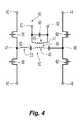
実施形態において、RF出力ステージ228は、図4により詳細に示されているように、位相シフト型、パルス幅および/または周波数変調型RFインバータとして構成され得る。特に、RF出力ステージ228は、ブリッジ回路40を含むHブリッジインバータとして示されている。ブリッジ回路40は、HVPS227と結合され、そこからDC電圧を受け取る。より詳細には、ブリッジ回路40は、一次巻線43と二次巻線45とを有する絶縁変圧器41を含む。一次巻線43は、第1の接続47と第2の接続49とを含む。第1の接続47は、ドレイン供給42とソース供給46とを含む。第2の接続49も、ドレイン供給44とソース供給48とを含む。ソース供給46、48およびドレイン供給42、44は、HVPS227と結合されている。 In an embodiment, the RF output stage 228 may be configured as a phase shift, pulse width and / or frequency modulated RF inverter, as shown in more detail in FIG. In particular, the RF output stage 228 is shown as an H-bridge inverter that includes a bridge circuit 40. Bridge circuit 40 is coupled with HVPS 227 and receives a DC voltage therefrom. More specifically, the bridge circuit 40 includes an
第1の接続47は、第1の一対の切り換えコンポーネント56および58を含み、第2の接続49は、第2の一対の切り換えコンポーネント60および62を含む。切り換えコンポーネント56、58、60、および62は、例えば金属酸化膜半導体電界効果トランジスタ(MOSFET)、絶縁ゲート双極トランジスタ(IGBT)のようなトランジスタ、リレーなどであることができる。 The
二次巻線45は、2つの出力端子80および82を含む。出力端子80および82は、それらの間に結合されている帯域通過フィルタ83を含み得る。第1の接続47および第2の接続49は、共振ネットワーク(例えば、タンク回路50)によって直列に接続されている。タンク回路50は、LCC構成に配列されている直列共振ネットワークであり得、該LCC構成は、インダクタ53と、キャパシタ52および54とを有し、一次巻線43は、キャパシタ52と54との間に結合されている。実施形態において、タンク回路50は、例えば並列共振ネットワークのような任意の他の適切な共振ネットワークであり得、複数のリアクタンス素子および受動素子を含み得る。 Secondary winding 45 includes two output terminals 80 and 82. Output terminals 80 and 82 may include a band pass filter 83 coupled between them. The
出力端子80、82は、単極電気外科器具、双極電気外科器具または切除器具(例えば、器具12、鉗子110)の活性およびリターン極に別個に接続され得る。さらに、または、代替として、出力端子80、82は、単一の活性またはリターンリードとの接続を共有し得る。一実施形態において、出力端子82は、リターン電極6と結合され、一方、出力端子80は、単一の器具上または複数の器具上のいずれかの活性リードと結合される。 The output terminals 80, 82 may be separately connected to the active and return poles of a monopolar electrosurgical instrument, bipolar electrosurgical instrument or ablation instrument (eg,
切り換えコンポーネント56、58、60、62は、コントローラ224(図3)と結合されている。コントローラ224は、所定の周波数または周波数(複数)で切り換えコンポーネント56、58、60、62を駆動し、ジェネレータ200の動作周波数範囲でもある所定の周波数の範囲で「オン」および「オフ」にし、それによって、第1の接続47および第2の接続49を開閉する。切り換えコンポーネント56、58、60、62がオンおよびオフにされる周波数は、コントローラ224によって制御される。コントローラ224は、切り換えコンポーネント56、58、60、62の各々にドライバ信号を供給するために、パルス幅変調型ドライバを含み得る。ドライバは、位相シフトされた駆動信号を放出し、該位相シフトされた駆動信号は、位相が異なる(例えば、180°位相が異なる)第1の成分と第2の成分とを有する。従って、切り換えコンポーネントの各対(例えば、56、58および60、62)は、その対向する対と180°位相が異なる位相関係を有する。換言すると、ドライバ信号は、切り換えコンポーネント56、58および60、62の対の各々を、同じ周波数で、しかし、同調しないで、「オン」位置と「オフ」位置との間で循環させ、第1の接続47および第2の接続49において180°位相が異なる2つの波形を作成する。さらに、切り換えコンポーネント56、58および60、62の各対に供給される駆動信号は、また、互いに対して位相シフトされ、変化するデューティサイクルの複数の波形を生成する。従って、位相シフトされたデュアル駆動信号を調節することは、動作RFデューティサイクルまたはパルス幅を変化させることを提供する。位相シフトされたデュアル駆動信号のデューティサイクルを変化させることは、RF振幅および送達される平均電力のより良好な制御を可能にする。位相シフトすることは、また、出力端子対80および82に送達される電力のインターリービングを可能にする。さらに、タンク回路50と組み合わされた場合、パルス幅または周波数変調は、負荷における出力電圧振幅を変化させるために用いられ得る。
一次巻線43との組み合わせでのタンク回路50は、矩形パルス幅変調型エネルギー(例えば、複数の高周波成分を有するACエネルギー)をRFエネルギー(例えば、約100kHz〜約100,000kHzの単一の高周波成分を有するACエネルギー)に変換する。切り換えコンポーネント56、58および60、62が閉じられた場合、高周波パルスは、タンク回路50のキャパシタ52、54に供給される。タンク回路50は、第1の接続47と第2の接続49との交互により、パルスを二相性正弦波形に変換する。タンク回路50は、上述のように、並列、直列、またはそれらの組み合わせのいずれかで配列されている複数の能動素子(例えば、受動素子およびキャパシタ)を含むことができる。 The
動作中において、一次巻線43は、同じ周波数の、しかし、互いに対して可変位相を有する2つの半正弦波形を作成し、それらは、次に、二次巻線45において組み合わさり、全波形を形成する。より詳細には、切り換えコンポーネント56、58および60、62の各対は、互いに対する所定の位相で供給される駆動信号によって駆動される。切り換えコンポーネント56、58および60、62の各対は、位相シフトされた駆動信号によって、同じ周波数で「オン」および「オフ」に交互に切り換えられる。 In operation, primary winding 43 creates two half-sine waveforms of the same frequency but with variable phase relative to each other, which are then combined in secondary winding 45 to produce the full waveform. Form. More specifically, each pair of switching
プロセッサ225は、ユーザインターフェース241と結合され、ユーザ入力に応答して、モード、ネルギー設定、および、ジェネレータ200の他のパラメータを改変するように構成されている。ジェネレータ200は、様々なモードで動作するように構成されている。一実施形態において、ジェネレータ200は、以下のモード、すなわち、切断、混合、凝固、止血による分割、放電治療、噴霧、それらの組み合わせなどを出力し得る。各モードは、予めプログラムされた電力曲線に基づいて動作し、該予めプログラムされた電力曲線は、負荷(例えば、組織)の変化するインピーダンスにおいてジェネレータ200によって出力される電力の量を制御する。各電力曲線は、電力、電圧、および、電流制御範囲を含み、該電力、電圧、および、電流制御範囲は、ユーザ選択の電力設定および負荷の測定されたインピーダンスによって画定される。 The
切断モードにおいて、ジェネレータ200は、約100Ω〜約2,000Ωのインピーダンス範囲にわたって、約1.414の波高率を有する所定の周波数(例えば、472kHz)で複数のRFサイクルを有する連続正弦波出力を供給し得る。切断モード電力曲線は、3つの領域、すなわち、低いインピーダンスの中への一定電流、中位のインピーダンスの中への一定電力、および高いインピーダンスの中への一定電圧を含み得る。混合モードにおいて、ジェネレータは、所定の周期的速度(periodic rate)で正弦波出力の交流バーストを供給し得、バーストサイクルは、第1の所定の繰り返し速度(例えば、約26.21kHz)で再発し、各バーストサイクルは、所定の周波数(例えば、472kHz)で複数の正弦波RFサイクルを含む。一実施形態において、バーストのデューティサイクルは、約50%であり得る。換言すると、各バーストサイクルに対して、電力は、時間の50%の間、オンであり、時間の50%の間、オフである。正弦波出力の一周期の波高率は、約1.414であり得る。一バーストサイクルの波高率は、約2.7であり得る。 In disconnected mode,
止血モードによる分割は、第2の所定の繰り返し速度(例えば、約28.3kHz)で再発する、所定の周波数(例えば、472kHz)での正弦波出力のバーストを含み得る。バーストのデューティサイクルは、約25%であり得る。すなわち、電力は、各サイクルの25%の間、オンであり、サイクルの残りの75%の間、オフである。一バーストサイクルの波高率は、約100Ω〜約2,000Ωのインピーダンスにわたって、約4.3であり得る。放電治療モードは、第3の所定の繰り返し速度(例えば、約30.66kHz)で再発する、所定の周波数(例えば、472kHz)での正弦波出力のバーストを含み得る。バーストのデューティサイクルは、約6.5%であり得、一バーストサイクルの波高率は、約100Ω〜約2,000Ωのインピーダンス範囲にわたって、約5.55であり得る。噴霧モードは、第4の所定の繰り返し速度(例えば、約21.7kHz)で再発する、所定の周波数(例えば、472kHz)での正弦波出力のバーストを含み得る。バーストのデューティサイクルは、約4.6%であり得、一バーストサイクルの波高率は、約100Ω〜約2,000Ωのインピーダンス範囲にわたって、約6.6であり得る。 Division by the hemostatic mode may include a burst of sinusoidal output at a predetermined frequency (eg, 472 kHz) that recurs at a second predetermined repetition rate (eg, about 28.3 kHz). The duty cycle of the burst can be about 25%. That is, power is on for 25% of each cycle and off for the remaining 75% of the cycle. The crest factor of one burst cycle can be about 4.3 over an impedance of about 100Ω to about 2,000Ω. The discharge therapy mode may include a burst of sinusoidal output at a predetermined frequency (eg, 472 kHz) that recurs at a third predetermined repetition rate (eg, about 30.66 kHz). The duty cycle of the burst can be about 6.5% and the crest factor of one burst cycle can be about 5.55 over an impedance range of about 100Ω to about 2,000Ω. The spray mode may include a burst of sinusoidal output at a predetermined frequency (eg, 472 kHz) that recurs at a fourth predetermined repetition rate (eg, about 21.7 kHz). The duty cycle of the burst can be about 4.6%, and the crest factor of one burst cycle can be about 6.6 over an impedance range of about 100Ω to about 2,000Ω.
ジェネレータ200は、RF出力ステージ228の共振インバータの電圧−電流特性に固有である電流、電力、および電圧境界に基づいて、様々な電気外科モード(例えば、アーク切断および凝固)の閉ループ制御を提供する。任意の共振インバータの電圧−電流特性は、プロットされた場合、共振ネットワークの出力インピーダンスに起因する電圧および電流制限領域によって境界が付けられた楕円を形成する。インバータのこの出力インピーダンスは、電気外科モードにおける動作中に観察される予想最小〜最大終端抵抗(例えば、組織の抵抗)の幾何平均に中心が置かれるように設計され得る。次に、RF出力ステージ228の動作特性は、ユーザによって要求される特定の電力設定の最大電圧および電流と一致するように整合させられ得る。
従来のジェネレータは、固定繰り返し速度で出力電圧波形をパルス化してジェネレータによって出力される所与のモード(例えば、凝固モード)に対する所望の波高率を生成することにより、電気外科エネルギーを組織に供給する。このシナリオにおいて、繰り返し速度は、ジェネレータの所与の出力モードに対する全ての電力、電圧、および電流設定にわたって固定されている。 Conventional generators deliver electrosurgical energy to tissue by pulsing the output voltage waveform at a fixed repetition rate to produce a desired crest factor for a given mode (eg, coagulation mode) output by the generator. . In this scenario, the repetition rate is fixed across all power, voltage, and current settings for a given output mode of the generator.
固定繰り返し速度で出力電圧波形をパルス化することは、位相シフト型インバータを用いる出力電圧波形の閉ループ制御に対して独特な問題を提起する。詳細には、特定のデューティサイクル(例えば、50%デューティサイクル)より上において、出力電圧波形は、ピーク電圧に到達し、ピーク電圧が到達されると、位相シフトのさらなる増大は、ピーク電圧に影響を与えない。従って、所与の電力設定に対して、負荷(例えば、組織)のインピーダンスが減少する場合、出力電圧波形の波高率が増大し、一方、ピーク電圧は、一定のままである。波高率のこの増大は、ストレイアーキング(stray arcing)につながり得る。手術中において、アーキングは、所望の外科的効果を達成するために生成される。高いアーク電流は、止血効果に対してうまく適しているが、しかし、熱移動を制限するために、電圧出力波形の波高率を制御することにより、ストレイアーキングを標的の組織に制限することも望ましい。本開示は、波高率を制御してこれらの目標を達成するように構成されている位相シフト型インバータを提供する。より詳細には、本開示は、負荷インピーダンスの変化に応答して、位相シフト型インバータの繰り返し速度および位相シフトを設定することにより、波高率の変化を低減する出力電圧波形を生成することを提供する。 Pulsing the output voltage waveform at a fixed repetition rate presents a unique problem for closed loop control of the output voltage waveform using a phase shift inverter. Specifically, above a certain duty cycle (eg, 50% duty cycle), the output voltage waveform reaches a peak voltage, and when the peak voltage is reached, further increase in phase shift affects the peak voltage. Not give. Thus, for a given power setting, if the load (eg, tissue) impedance decreases, the crest factor of the output voltage waveform increases while the peak voltage remains constant. This increase in crest factor can lead to stray arcing. During surgery, arcing is generated to achieve the desired surgical effect. High arc currents are well suited for hemostatic effects, but it is also desirable to limit stray arcing to the target tissue by controlling the crest factor of the voltage output waveform to limit heat transfer . The present disclosure provides a phase shift inverter configured to control the crest factor to achieve these goals. More particularly, the present disclosure provides for generating an output voltage waveform that reduces the change in crest factor by setting the repetition rate and phase shift of a phase shift inverter in response to a change in load impedance. To do.
ここで図5Aを参照すると、関数時間(t)として、プロット300は、タンク回路50(図4)の電圧、または、いわゆる「タンク電圧」(「Vtank」)を示しており、電圧出力プロット310は、電圧源(例えば、RF出力ステージ228)からの電圧出力波形(「Vout」)を示している。時間t1において、切り換えコンポーネント56、58および60、62のうちの1つの対または両方の対は、「オン」にされ、それによって、タンク電圧Vtankは、ゼロボルトから正のピーク電圧+Vtankpkまで増大する。時間t1において、電圧出力Voutは、ゼロボルトであり、電圧出力Voutは、プロット310上のポイント325によって示されている正のピーク電圧+Voutpkに到達するまで増大する。時間t2において、切り換えコンポーネント56、58および60、62のうちの1つの対または両方の対が「オフ」にされ、それによって、タンク電圧Vtankが、+Vtankpkからゼロボルトまで減少し、一方、出力電圧Voutは、減少しつつある。すなわち、Vtankが、ピーク電圧Vtankpkにある間、出力電圧Voutは、そのピーク電圧Voutpkまで増大し、Vtankが、時間t2においてゼロボルトまで減少する前に減少し始める。時間t3において、切り換えコンポーネント56、58および60、62のうちの1つの対または両方の対は、「オン」にされ、それによって、タンク電圧Vtankは、ゼロ電圧から負のピーク電圧−Vtankpkまで増大する。時間t3において、電圧出力Voutは、ゼロボルトであり、負のピーク電圧−Voutpkを達成することに向かって減少している。負のVoutの応答は、上述された正のVoutの半サイクルの応答と実質的に同様である。Referring now to FIG. 5A, as function time (t),
ピーク出力電圧Voutpkの大きさは、ブリッジ回路40におけるタンク回路50(図4)の周波数応答および負荷(例えば、組織)によって少なくとも部分的に決定される。従って、出力電圧Voutは、タンク電圧Vtankのパルスに起因するタンク回路50のステップ応答に従う。タンク電圧Vtankパルスの持続時間は、出力電圧Voutが、Voutプロット310の部分340によって示される各半サイクル中にどれくらい長く上昇するかを、従って、ピーク出力電圧Voutpkが、どの程度まで増大するかを決定する。比較的長いデューティサイクル(例えば、50%以上デューティサイクル)に対して、出力電圧Voutは、最大達成可能ピーク325まで上昇し、Vtankパルスの終了前に下降し始める。デューティサイクルが比較的短い場合(例えば、50%未満デューティサイクル)、パルスは、出力電圧Voutが、その最大達成可能ピークに到達するために十分長く続かない。これは、ピーク出力電圧Voutpkが、出力電圧波形Voutのデューティサイクルを制御することによって、デューティサイクルの所与の範囲にわたって制御されることを可能にする。The magnitude of the peak output voltage Voutpk is determined at least in part by the frequency response of the tank circuit 50 (FIG. 4) in the bridge circuit 40 and the load (eg, tissue). Therefore, the output voltage Vout follows the step response of the
一部の実施形態において、電圧出力波形Voutの波高率は、ジェネレータの所与の電力、電圧、および/もしくは電流設定に対する繰り返し速度を設定すること、ならびに/または、ブリッジ回路40の所与の位相シフト設定によって制御され得る。出力電圧Voutが、タンク電圧Vtankが、ブリッジ回路40の切り換えコンポーネント56、58および60、62のうちの1つの対または両方の対を「オフ」にしたことに応じてゼロボルトに等しくなった場合、増大しつつあるように、ブリッジ回路40のデューティサイクルは、繰り返し速度を設定することによって、制御され得る。例えば、繰り返し速度は、電気外科波形のデューティサイクルを減少または増大させるために、ジェネレータ200の特定の出力設定(例えば、電力、電圧、電流、その他)に対して、増大または減少させられ得る。 In some embodiments, the crest factor of the voltage output waveform Vout sets the repetition rate for a given power, voltage and / or current setting of the generator and / or a given phase of the bridge circuit 40. Can be controlled by shift setting. If the output voltage Vout becomes equal to zero volts in response to the tank voltage Vtank “turning off” one or both of the switching
図5Bは、関数時間(t)として、タンク回路50のタンク電圧Vtankのプロット400、および、電圧源(例えば、RF出力ステージ228)からの電圧出力波形Voutのプロット410を示している。時間t1Aにおいて、切り換えコンポーネント56、58および60、62のうちの1つの対または両方の対は、「オン」にされ、それによって、タンク電圧Vtankは、ゼロボルトから正のピーク電圧+Vtankpkまで増大する。時間t1Aにおいて、電圧出力Voutは、ゼロボルトであり、電圧出力Voutは、プロット410上のポイント425によって示されている正のピーク電圧+Voutpkまで増大する。時間t2Aにおいて、切り換えコンポーネント56、58および60、62のうちの1つの対または両方の対が、「オフ」にされ、それによって、タンク電圧Vtankが、+Vtankpkからゼロボルトまで減少し、電圧出力Voutは、増大しつつある。時間t2Aにおいて、出力電圧Voutは、プロット410上のポイント425によって示されているその正のピーク+Voutpkに到達する。時間t3Aにおいて、切り換えコンポーネント56、58および60、62のうちの1つの対または両方の対は、「オン」にされ、それによって、タンク電圧Vtankは、ゼロボルトから減少し、その負のピーク−Vtankpkに到達する。図5Bに示されているプロット410とは対照的に、図5Aのプロット310によって示されている電圧出力波形Voutのデューティサイクルは、Vtankが、時間t2において、Vtankpkからゼロボルトまで減少する場合、出力電圧波形Voutが減少しつつあるように設定されている。図5Bは、図5Aのデューティサイクルに対して、デューティサイクルを減少させることの効果を示している。特に、繰り返し速度を増大させることは、同じRMS電圧を維持するために、電圧出力波形Voutのデューティサイクルを減少させる。タンク電圧Vtankパルスの持続時間を減少させることによって、出力電圧Voutは、その最大達成可能ピークに到達することが効果的に防止される。従って、このシナリオにおいて、ピーク出力電圧Vpeakは、デューティサイクルによって制御される。負のVoutの応答は、上述された正のVoutの半サイクルの応答と実質的に同様である。FIG. 5B shows plot 400 of tank voltage Vtank of
本開示の幾つかの実施形態が、図面に示されること、および/または、本明細書に記述されることが行われたが、本開示がそれらに限定されることは意図されていない。なぜなら、本開示は、当該技術分野が許す限り範囲が広くあること、および、本明細書は、同様に読まれることが意図されているからである。従って、上述は、限定するものとして解釈されるべきではなく、単なる、特定の実施形態の例示として解釈されるべきである。当業者は、本明細書に添付されている請求項の範囲および精神内で、他の改変に想到する。 Although some embodiments of the present disclosure have been shown in the drawings and / or described herein, it is not intended that the present disclosure be limited thereto. This is because the present disclosure is as broad as the technical field allows, and the specification is intended to be read as well. Therefore, the above description should not be construed as limiting, but merely as exemplifications of particular embodiments. Those skilled in the art will envision other modifications within the scope and spirit of the claims appended hereto.
10 双極および単極電気外科システム
12 器具
13 活性電極
14 供給ライン
16 リターン電極パッド
18 リターンライン
110 電気外科鉗子
111 筐体
112 シャフト
113 顎部材
114 活性電極
115 顎部材
116 リターン電極
118 ケーブル
200 ジェネレータ
224 コントローラ
225 プロセッサ
226 メモリ
227 高電圧DC電力供給
228 RF出力ステージ
230 活性端子
232 リターン端子10 Bipolar and
Claims (13)
Translated fromJapanese電源と結合されているRFインバータを備えたRF出力ステージであって、該RF出力ステージは、選択されたエネルギー設定で、少なくとも1つの電気外科波形を生成するように構成され、該少なくとも1つの電気外科波形は、デューティサイクルと波高率とを有する、RF出力ステージと、
該選択されたエネルギー設定に基づいて、該少なくとも1つの電気外科波形の繰り返し速度を調節することにより、該少なくとも1つの電気外科波形の該デューティサイクルを調整するように構成されているコントローラと、
該少なくとも1つの電気外科波形の出力電圧を測定するように構成されているセンサと
を備え、該コントローラは、該出力電圧が増大しつつある場合、該繰り返し速度に基づいて、該RFインバータに制御信号を供給することにより、該少なくとも1つの電気外科波形の該波高率を調整するように構成されている、
電気外科ジェネレータ。An electrosurgical generator comprising:
An RF output stage with an RF inverter coupled to a power supply, wherein the RF output stage is configured to generate at least one electrosurgical waveform at a selected energy setting, the at least one electrical The surgical waveform includes an RF output stage having a duty cycle and a crest factor;
A controller configured to adjust the duty cycle of the at least one electrosurgical waveform by adjusting a repetition rate of the at least one electrosurgical waveform based on the selected energy setting;
A sensor configured to measure an output voltage of the at least one electrosurgical waveform, wherein the controller controls the RF inverter based on the repetition rate when the output voltage is increasing. Configured to adjust the crest factor of the at least one electrosurgical waveform by providing a signal;
Electrosurgical generator.
電気外科ジェネレータを備え、該電気外科ジェネレータは、
電源と結合されているRFインバータを備えたRF出力ステージであって、該RF出力ステージは、選択されたエネルギー設定で、少なくとも1つの電気外科波形を生成するように構成され、該少なくとも1つの電気外科波形は、デューティサイクルと波高率とを有する、RF出力ステージと、
該選択されたエネルギー設定に基づいて、該少なくとも1つの電気外科波形の繰り返し速度を調節することにより、該少なくとも1つの電気外科波形の該デューティサイクルを調整するように構成されているコントローラと、
該少なくとも1つの電気外科波形の出力電圧を測定するように構成されているセンサと
を備え、該コントローラは、該出力電圧が増大しつつある場合、該繰り返し速度に基づいて、該RFインバータに制御信号を供給することにより、該少なくとも1つの電気外科波形の該波高率を調整するように構成されている、
電気外科システム。An electrosurgical system comprising:
An electrosurgical generator comprising:
An RF output stage with an RF inverter coupled to a power supply, wherein the RF output stage is configured to generate at least one electrosurgical waveform at a selected energy setting, the at least one electrical The surgical waveform includes an RF output stage having a duty cycle and a crest factor;
A controller configured to adjust the duty cycle of the at least one electrosurgical waveform by adjusting a repetition rate of the at least one electrosurgical waveform based on the selected energy setting;
A sensor configured to measure an output voltage of the at least one electrosurgical waveform, wherein the controller controls the RF inverter based on the repetition rate when the output voltage is increasing. Configured to adjust the crest factor of the at least one electrosurgical waveform by providing a signal;
Electrosurgical system.
Applications Claiming Priority (4)
| Application Number | Priority Date | Filing Date | Title |
|---|---|---|---|
| US201361789080P | 2013-03-15 | 2013-03-15 | |
| US61/789,080 | 2013-03-15 | ||
| US14/098,859US9283028B2 (en) | 2013-03-15 | 2013-12-06 | Crest-factor control of phase-shifted inverter |
| US14/098,859 | 2013-12-06 |
Publications (2)
| Publication Number | Publication Date |
|---|---|
| JP2014180539Atrue JP2014180539A (en) | 2014-09-29 |
| JP6537222B2 JP6537222B2 (en) | 2019-07-03 |
Family
ID=50238120
Family Applications (1)
| Application Number | Title | Priority Date | Filing Date |
|---|---|---|---|
| JP2014033921AExpired - Fee RelatedJP6537222B2 (en) | 2013-03-15 | 2014-02-25 | Crest factor control of phase shift inverter |
Country Status (5)
| Country | Link |
|---|---|
| US (1) | US9283028B2 (en) |
| EP (1) | EP2777577B1 (en) |
| JP (1) | JP6537222B2 (en) |
| AU (1) | AU2014200201A1 (en) |
| CA (1) | CA2845763C (en) |
Cited By (1)
| Publication number | Priority date | Publication date | Assignee | Title |
|---|---|---|---|---|
| JP2022084008A (en)* | 2020-11-25 | 2022-06-06 | バイオセンス・ウエブスター・(イスラエル)・リミテッド | Single frequency switch mode power generator with phase shifter |
Families Citing this family (556)
| Publication number | Priority date | Publication date | Assignee | Title |
|---|---|---|---|---|
| US20070084897A1 (en) | 2003-05-20 | 2007-04-19 | Shelton Frederick E Iv | Articulating surgical stapling instrument incorporating a two-piece e-beam firing mechanism |
| US9060770B2 (en) | 2003-05-20 | 2015-06-23 | Ethicon Endo-Surgery, Inc. | Robotically-driven surgical instrument with E-beam driver |
| US9072535B2 (en) | 2011-05-27 | 2015-07-07 | Ethicon Endo-Surgery, Inc. | Surgical stapling instruments with rotatable staple deployment arrangements |
| US8215531B2 (en) | 2004-07-28 | 2012-07-10 | Ethicon Endo-Surgery, Inc. | Surgical stapling instrument having a medical substance dispenser |
| US11890012B2 (en) | 2004-07-28 | 2024-02-06 | Cilag Gmbh International | Staple cartridge comprising cartridge body and attached support |
| US11998198B2 (en) | 2004-07-28 | 2024-06-04 | Cilag Gmbh International | Surgical stapling instrument incorporating a two-piece E-beam firing mechanism |
| US10159482B2 (en) | 2005-08-31 | 2018-12-25 | Ethicon Llc | Fastener cartridge assembly comprising a fixed anvil and different staple heights |
| US9237891B2 (en) | 2005-08-31 | 2016-01-19 | Ethicon Endo-Surgery, Inc. | Robotically-controlled surgical stapling devices that produce formed staples having different lengths |
| US11484312B2 (en) | 2005-08-31 | 2022-11-01 | Cilag Gmbh International | Staple cartridge comprising a staple driver arrangement |
| US7934630B2 (en) | 2005-08-31 | 2011-05-03 | Ethicon Endo-Surgery, Inc. | Staple cartridges for forming staples having differing formed staple heights |
| US7669746B2 (en) | 2005-08-31 | 2010-03-02 | Ethicon Endo-Surgery, Inc. | Staple cartridges for forming staples having differing formed staple heights |
| US11246590B2 (en) | 2005-08-31 | 2022-02-15 | Cilag Gmbh International | Staple cartridge including staple drivers having different unfired heights |
| US20070106317A1 (en) | 2005-11-09 | 2007-05-10 | Shelton Frederick E Iv | Hydraulically and electrically actuated articulation joints for surgical instruments |
| US11224427B2 (en) | 2006-01-31 | 2022-01-18 | Cilag Gmbh International | Surgical stapling system including a console and retraction assembly |
| US11793518B2 (en) | 2006-01-31 | 2023-10-24 | Cilag Gmbh International | Powered surgical instruments with firing system lockout arrangements |
| US20120292367A1 (en) | 2006-01-31 | 2012-11-22 | Ethicon Endo-Surgery, Inc. | Robotically-controlled end effector |
| US8708213B2 (en) | 2006-01-31 | 2014-04-29 | Ethicon Endo-Surgery, Inc. | Surgical instrument having a feedback system |
| US11278279B2 (en) | 2006-01-31 | 2022-03-22 | Cilag Gmbh International | Surgical instrument assembly |
| US7753904B2 (en) | 2006-01-31 | 2010-07-13 | Ethicon Endo-Surgery, Inc. | Endoscopic surgical instrument with a handle that can articulate with respect to the shaft |
| US20110295295A1 (en) | 2006-01-31 | 2011-12-01 | Ethicon Endo-Surgery, Inc. | Robotically-controlled surgical instrument having recording capabilities |
| US20110024477A1 (en) | 2009-02-06 | 2011-02-03 | Hall Steven G | Driven Surgical Stapler Improvements |
| US8820603B2 (en) | 2006-01-31 | 2014-09-02 | Ethicon Endo-Surgery, Inc. | Accessing data stored in a memory of a surgical instrument |
| US8186555B2 (en) | 2006-01-31 | 2012-05-29 | Ethicon Endo-Surgery, Inc. | Motor-driven surgical cutting and fastening instrument with mechanical closure system |
| US7845537B2 (en) | 2006-01-31 | 2010-12-07 | Ethicon Endo-Surgery, Inc. | Surgical instrument having recording capabilities |
| US8992422B2 (en) | 2006-03-23 | 2015-03-31 | Ethicon Endo-Surgery, Inc. | Robotically-controlled endoscopic accessory channel |
| US8322455B2 (en) | 2006-06-27 | 2012-12-04 | Ethicon Endo-Surgery, Inc. | Manually driven surgical cutting and fastening instrument |
| US7506791B2 (en) | 2006-09-29 | 2009-03-24 | Ethicon Endo-Surgery, Inc. | Surgical stapling instrument with mechanical mechanism for limiting maximum tissue compression |
| US10568652B2 (en) | 2006-09-29 | 2020-02-25 | Ethicon Llc | Surgical staples having attached drivers of different heights and stapling instruments for deploying the same |
| US11980366B2 (en) | 2006-10-03 | 2024-05-14 | Cilag Gmbh International | Surgical instrument |
| US8684253B2 (en) | 2007-01-10 | 2014-04-01 | Ethicon Endo-Surgery, Inc. | Surgical instrument with wireless communication between a control unit of a robotic system and remote sensor |
| US8632535B2 (en) | 2007-01-10 | 2014-01-21 | Ethicon Endo-Surgery, Inc. | Interlock and surgical instrument including same |
| US11291441B2 (en) | 2007-01-10 | 2022-04-05 | Cilag Gmbh International | Surgical instrument with wireless communication between control unit and remote sensor |
| US8652120B2 (en) | 2007-01-10 | 2014-02-18 | Ethicon Endo-Surgery, Inc. | Surgical instrument with wireless communication between control unit and sensor transponders |
| US20080169333A1 (en) | 2007-01-11 | 2008-07-17 | Shelton Frederick E | Surgical stapler end effector with tapered distal end |
| US11039836B2 (en) | 2007-01-11 | 2021-06-22 | Cilag Gmbh International | Staple cartridge for use with a surgical stapling instrument |
| US7673782B2 (en) | 2007-03-15 | 2010-03-09 | Ethicon Endo-Surgery, Inc. | Surgical stapling instrument having a releasable buttress material |
| US8893946B2 (en) | 2007-03-28 | 2014-11-25 | Ethicon Endo-Surgery, Inc. | Laparoscopic tissue thickness and clamp load measuring devices |
| US11564682B2 (en) | 2007-06-04 | 2023-01-31 | Cilag Gmbh International | Surgical stapler device |
| US8931682B2 (en) | 2007-06-04 | 2015-01-13 | Ethicon Endo-Surgery, Inc. | Robotically-controlled shaft based rotary drive systems for surgical instruments |
| US7753245B2 (en) | 2007-06-22 | 2010-07-13 | Ethicon Endo-Surgery, Inc. | Surgical stapling instruments |
| US11849941B2 (en) | 2007-06-29 | 2023-12-26 | Cilag Gmbh International | Staple cartridge having staple cavities extending at a transverse angle relative to a longitudinal cartridge axis |
| US7819298B2 (en) | 2008-02-14 | 2010-10-26 | Ethicon Endo-Surgery, Inc. | Surgical stapling apparatus with control features operable with one hand |
| US11986183B2 (en) | 2008-02-14 | 2024-05-21 | Cilag Gmbh International | Surgical cutting and fastening instrument comprising a plurality of sensors to measure an electrical parameter |
| US7866527B2 (en) | 2008-02-14 | 2011-01-11 | Ethicon Endo-Surgery, Inc. | Surgical stapling apparatus with interlockable firing system |
| US8573465B2 (en) | 2008-02-14 | 2013-11-05 | Ethicon Endo-Surgery, Inc. | Robotically-controlled surgical end effector system with rotary actuated closure systems |
| US8636736B2 (en) | 2008-02-14 | 2014-01-28 | Ethicon Endo-Surgery, Inc. | Motorized surgical cutting and fastening instrument |
| JP5410110B2 (en) | 2008-02-14 | 2014-02-05 | エシコン・エンド−サージェリィ・インコーポレイテッド | Surgical cutting / fixing instrument with RF electrode |
| US9179912B2 (en) | 2008-02-14 | 2015-11-10 | Ethicon Endo-Surgery, Inc. | Robotically-controlled motorized surgical cutting and fastening instrument |
| US8758391B2 (en) | 2008-02-14 | 2014-06-24 | Ethicon Endo-Surgery, Inc. | Interchangeable tools for surgical instruments |
| US11272927B2 (en) | 2008-02-15 | 2022-03-15 | Cilag Gmbh International | Layer arrangements for surgical staple cartridges |
| US9585657B2 (en) | 2008-02-15 | 2017-03-07 | Ethicon Endo-Surgery, Llc | Actuator for releasing a layer of material from a surgical end effector |
| US9005230B2 (en) | 2008-09-23 | 2015-04-14 | Ethicon Endo-Surgery, Inc. | Motorized surgical instrument |
| US8210411B2 (en) | 2008-09-23 | 2012-07-03 | Ethicon Endo-Surgery, Inc. | Motor-driven surgical cutting instrument |
| US9386983B2 (en) | 2008-09-23 | 2016-07-12 | Ethicon Endo-Surgery, Llc | Robotically-controlled motorized surgical instrument |
| US11648005B2 (en) | 2008-09-23 | 2023-05-16 | Cilag Gmbh International | Robotically-controlled motorized surgical instrument with an end effector |
| US8608045B2 (en) | 2008-10-10 | 2013-12-17 | Ethicon Endo-Sugery, Inc. | Powered surgical cutting and stapling apparatus with manually retractable firing system |
| US8517239B2 (en) | 2009-02-05 | 2013-08-27 | Ethicon Endo-Surgery, Inc. | Surgical stapling instrument comprising a magnetic element driver |
| RU2525225C2 (en) | 2009-02-06 | 2014-08-10 | Этикон Эндо-Серджери, Инк. | Improvement of drive surgical suturing instrument |
| US8444036B2 (en) | 2009-02-06 | 2013-05-21 | Ethicon Endo-Surgery, Inc. | Motor driven surgical fastener device with mechanisms for adjusting a tissue gap within the end effector |
| US8851354B2 (en) | 2009-12-24 | 2014-10-07 | Ethicon Endo-Surgery, Inc. | Surgical cutting instrument that analyzes tissue thickness |
| US8220688B2 (en) | 2009-12-24 | 2012-07-17 | Ethicon Endo-Surgery, Inc. | Motor-driven surgical cutting instrument with electric actuator directional control assembly |
| US8783543B2 (en) | 2010-07-30 | 2014-07-22 | Ethicon Endo-Surgery, Inc. | Tissue acquisition arrangements and methods for surgical stapling devices |
| US9788834B2 (en) | 2010-09-30 | 2017-10-17 | Ethicon Llc | Layer comprising deployable attachment members |
| US11812965B2 (en) | 2010-09-30 | 2023-11-14 | Cilag Gmbh International | Layer of material for a surgical end effector |
| US9386988B2 (en) | 2010-09-30 | 2016-07-12 | Ethicon End-Surgery, LLC | Retainer assembly including a tissue thickness compensator |
| US10945731B2 (en) | 2010-09-30 | 2021-03-16 | Ethicon Llc | Tissue thickness compensator comprising controlled release and expansion |
| US9351730B2 (en) | 2011-04-29 | 2016-05-31 | Ethicon Endo-Surgery, Llc | Tissue thickness compensator comprising channels |
| US9016542B2 (en) | 2010-09-30 | 2015-04-28 | Ethicon Endo-Surgery, Inc. | Staple cartridge comprising compressible distortion resistant components |
| US12213666B2 (en) | 2010-09-30 | 2025-02-04 | Cilag Gmbh International | Tissue thickness compensator comprising layers |
| US11925354B2 (en) | 2010-09-30 | 2024-03-12 | Cilag Gmbh International | Staple cartridge comprising staples positioned within a compressible portion thereof |
| US11298125B2 (en) | 2010-09-30 | 2022-04-12 | Cilag Gmbh International | Tissue stapler having a thickness compensator |
| US9364233B2 (en) | 2010-09-30 | 2016-06-14 | Ethicon Endo-Surgery, Llc | Tissue thickness compensators for circular surgical staplers |
| US9232941B2 (en) | 2010-09-30 | 2016-01-12 | Ethicon Endo-Surgery, Inc. | Tissue thickness compensator comprising a reservoir |
| US9629814B2 (en) | 2010-09-30 | 2017-04-25 | Ethicon Endo-Surgery, Llc | Tissue thickness compensator configured to redistribute compressive forces |
| US8695866B2 (en) | 2010-10-01 | 2014-04-15 | Ethicon Endo-Surgery, Inc. | Surgical instrument having a power control circuit |
| AU2012250197B2 (en) | 2011-04-29 | 2017-08-10 | Ethicon Endo-Surgery, Inc. | Staple cartridge comprising staples positioned within a compressible portion thereof |
| US11207064B2 (en) | 2011-05-27 | 2021-12-28 | Cilag Gmbh International | Automated end effector component reloading system for use with a robotic system |
| US9044230B2 (en) | 2012-02-13 | 2015-06-02 | Ethicon Endo-Surgery, Inc. | Surgical cutting and fastening instrument with apparatus for determining cartridge and firing motion status |
| JP6224070B2 (en) | 2012-03-28 | 2017-11-01 | エシコン・エンド−サージェリィ・インコーポレイテッドEthicon Endo−Surgery,Inc. | Retainer assembly including tissue thickness compensator |
| MX358135B (en) | 2012-03-28 | 2018-08-06 | Ethicon Endo Surgery Inc | Tissue thickness compensator comprising a plurality of layers. |
| BR112014024098B1 (en) | 2012-03-28 | 2021-05-25 | Ethicon Endo-Surgery, Inc. | staple cartridge |
| US11871901B2 (en) | 2012-05-20 | 2024-01-16 | Cilag Gmbh International | Method for situational awareness for surgical network or surgical network connected device capable of adjusting function based on a sensed situation or usage |
| US9101358B2 (en) | 2012-06-15 | 2015-08-11 | Ethicon Endo-Surgery, Inc. | Articulatable surgical instrument comprising a firing drive |
| BR112014032776B1 (en) | 2012-06-28 | 2021-09-08 | Ethicon Endo-Surgery, Inc | SURGICAL INSTRUMENT SYSTEM AND SURGICAL KIT FOR USE WITH A SURGICAL INSTRUMENT SYSTEM |
| US11278284B2 (en) | 2012-06-28 | 2022-03-22 | Cilag Gmbh International | Rotary drive arrangements for surgical instruments |
| US20140001231A1 (en) | 2012-06-28 | 2014-01-02 | Ethicon Endo-Surgery, Inc. | Firing system lockout arrangements for surgical instruments |
| US9282974B2 (en) | 2012-06-28 | 2016-03-15 | Ethicon Endo-Surgery, Llc | Empty clip cartridge lockout |
| US20140005718A1 (en) | 2012-06-28 | 2014-01-02 | Ethicon Endo-Surgery, Inc. | Multi-functional powered surgical device with external dissection features |
| US12383267B2 (en) | 2012-06-28 | 2025-08-12 | Cilag Gmbh International | Robotically powered surgical device with manually-actuatable reversing system |
| JP6290201B2 (en) | 2012-06-28 | 2018-03-07 | エシコン・エンド−サージェリィ・インコーポレイテッドEthicon Endo−Surgery,Inc. | Lockout for empty clip cartridge |
| US9408606B2 (en) | 2012-06-28 | 2016-08-09 | Ethicon Endo-Surgery, Llc | Robotically powered surgical device with manually-actuatable reversing system |
| US9289256B2 (en) | 2012-06-28 | 2016-03-22 | Ethicon Endo-Surgery, Llc | Surgical end effectors having angled tissue-contacting surfaces |
| US9204921B2 (en) | 2012-12-13 | 2015-12-08 | Cook Medical Technologies Llc | RF energy controller and method for electrosurgical medical devices |
| US9364277B2 (en) | 2012-12-13 | 2016-06-14 | Cook Medical Technologies Llc | RF energy controller and method for electrosurgical medical devices |
| BR112015021082B1 (en) | 2013-03-01 | 2022-05-10 | Ethicon Endo-Surgery, Inc | surgical instrument |
| RU2672520C2 (en) | 2013-03-01 | 2018-11-15 | Этикон Эндо-Серджери, Инк. | Hingedly turnable surgical instruments with conducting ways for signal transfer |
| US9629629B2 (en) | 2013-03-14 | 2017-04-25 | Ethicon Endo-Surgey, LLC | Control systems for surgical instruments |
| US9808244B2 (en) | 2013-03-14 | 2017-11-07 | Ethicon Llc | Sensor arrangements for absolute positioning system for surgical instruments |
| US9826976B2 (en) | 2013-04-16 | 2017-11-28 | Ethicon Llc | Motor driven surgical instruments with lockable dual drive shafts |
| BR112015026109B1 (en) | 2013-04-16 | 2022-02-22 | Ethicon Endo-Surgery, Inc | surgical instrument |
| US10729484B2 (en)* | 2013-07-16 | 2020-08-04 | Covidien Lp | Electrosurgical generator with continuously and arbitrarily variable crest factor |
| US9872719B2 (en) | 2013-07-24 | 2018-01-23 | Covidien Lp | Systems and methods for generating electrosurgical energy using a multistage power converter |
| MX369362B (en) | 2013-08-23 | 2019-11-06 | Ethicon Endo Surgery Llc | Firing member retraction devices for powered surgical instruments. |
| US9775609B2 (en) | 2013-08-23 | 2017-10-03 | Ethicon Llc | Tamper proof circuit for surgical instrument battery pack |
| US9839469B2 (en) | 2013-09-24 | 2017-12-12 | Covidien Lp | Systems and methods for improving efficiency of electrosurgical generators |
| US9770283B2 (en) | 2013-09-24 | 2017-09-26 | Covidien Lp | Systems and methods for improving efficiency of electrosurgical generators |
| US10130412B2 (en) | 2013-09-26 | 2018-11-20 | Covidien Lp | Systems and methods for estimating tissue parameters using surgical devices |
| US9962161B2 (en) | 2014-02-12 | 2018-05-08 | Ethicon Llc | Deliverable surgical instrument |
| JP6462004B2 (en) | 2014-02-24 | 2019-01-30 | エシコン エルエルシー | Fastening system with launcher lockout |
| US10166061B2 (en)* | 2014-03-17 | 2019-01-01 | Intuitive Surgical Operations, Inc. | Teleoperated surgical system equipment with user interface |
| BR112016021943B1 (en) | 2014-03-26 | 2022-06-14 | Ethicon Endo-Surgery, Llc | SURGICAL INSTRUMENT FOR USE BY AN OPERATOR IN A SURGICAL PROCEDURE |
| US10013049B2 (en) | 2014-03-26 | 2018-07-03 | Ethicon Llc | Power management through sleep options of segmented circuit and wake up control |
| US20150272580A1 (en) | 2014-03-26 | 2015-10-01 | Ethicon Endo-Surgery, Inc. | Verification of number of battery exchanges/procedure count |
| US10004497B2 (en) | 2014-03-26 | 2018-06-26 | Ethicon Llc | Interface systems for use with surgical instruments |
| US12232723B2 (en) | 2014-03-26 | 2025-02-25 | Cilag Gmbh International | Systems and methods for controlling a segmented circuit |
| US10492850B2 (en) | 2014-04-04 | 2019-12-03 | Covidien Lp | Systems and methods for calculating tissue impedance in electrosurgery |
| US10327764B2 (en) | 2014-09-26 | 2019-06-25 | Ethicon Llc | Method for creating a flexible staple line |
| US10470768B2 (en) | 2014-04-16 | 2019-11-12 | Ethicon Llc | Fastener cartridge including a layer attached thereto |
| BR112016023825B1 (en) | 2014-04-16 | 2022-08-02 | Ethicon Endo-Surgery, Llc | STAPLE CARTRIDGE FOR USE WITH A SURGICAL STAPLER AND STAPLE CARTRIDGE FOR USE WITH A SURGICAL INSTRUMENT |
| US20150297225A1 (en) | 2014-04-16 | 2015-10-22 | Ethicon Endo-Surgery, Inc. | Fastener cartridges including extensions having different configurations |
| CN106456159B (en) | 2014-04-16 | 2019-03-08 | 伊西康内外科有限责任公司 | Fastener Cartridge Assembly and Nail Retainer Cover Arrangement |
| CN106456176B (en) | 2014-04-16 | 2019-06-28 | 伊西康内外科有限责任公司 | Fastener Cartridge Including Extensions With Different Configurations |
| US11311294B2 (en) | 2014-09-05 | 2022-04-26 | Cilag Gmbh International | Powered medical device including measurement of closure state of jaws |
| US10135242B2 (en) | 2014-09-05 | 2018-11-20 | Ethicon Llc | Smart cartridge wake up operation and data retention |
| BR112017004361B1 (en) | 2014-09-05 | 2023-04-11 | Ethicon Llc | ELECTRONIC SYSTEM FOR A SURGICAL INSTRUMENT |
| US10105142B2 (en) | 2014-09-18 | 2018-10-23 | Ethicon Llc | Surgical stapler with plurality of cutting elements |
| CN107427300B (en) | 2014-09-26 | 2020-12-04 | 伊西康有限责任公司 | Surgical suture buttresses and auxiliary materials |
| US11523821B2 (en) | 2014-09-26 | 2022-12-13 | Cilag Gmbh International | Method for creating a flexible staple line |
| US10076325B2 (en) | 2014-10-13 | 2018-09-18 | Ethicon Llc | Surgical stapling apparatus comprising a tissue stop |
| US9924944B2 (en) | 2014-10-16 | 2018-03-27 | Ethicon Llc | Staple cartridge comprising an adjunct material |
| US11141153B2 (en) | 2014-10-29 | 2021-10-12 | Cilag Gmbh International | Staple cartridges comprising driver arrangements |
| US10517594B2 (en) | 2014-10-29 | 2019-12-31 | Ethicon Llc | Cartridge assemblies for surgical staplers |
| US11504192B2 (en) | 2014-10-30 | 2022-11-22 | Cilag Gmbh International | Method of hub communication with surgical instrument systems |
| WO2016070009A1 (en)* | 2014-10-31 | 2016-05-06 | Medtronic Advanced Energy Llc | Power monitoring circuitry and method for reducing leakage current in rf generators |
| US9844376B2 (en) | 2014-11-06 | 2017-12-19 | Ethicon Llc | Staple cartridge comprising a releasable adjunct material |
| US10188448B2 (en) | 2014-11-21 | 2019-01-29 | Covidien Lp | Electrosurgical system for multi-frequency interrogation of parasitic parameters of an electrosurgical instrument |
| US10736636B2 (en) | 2014-12-10 | 2020-08-11 | Ethicon Llc | Articulatable surgical instrument system |
| US9844374B2 (en) | 2014-12-18 | 2017-12-19 | Ethicon Llc | Surgical instrument systems comprising an articulatable end effector and means for adjusting the firing stroke of a firing member |
| MX389118B (en) | 2014-12-18 | 2025-03-20 | Ethicon Llc | SURGICAL INSTRUMENT WITH AN ANVIL THAT CAN BE SELECTIVELY MOVED ON A DISCRETE, NON-MOBILE AXIS RELATIVE TO A STAPLE CARTRIDGE. |
| US9844375B2 (en) | 2014-12-18 | 2017-12-19 | Ethicon Llc | Drive arrangements for articulatable surgical instruments |
| US10188385B2 (en) | 2014-12-18 | 2019-01-29 | Ethicon Llc | Surgical instrument system comprising lockable systems |
| US9987000B2 (en) | 2014-12-18 | 2018-06-05 | Ethicon Llc | Surgical instrument assembly comprising a flexible articulation system |
| US9943309B2 (en) | 2014-12-18 | 2018-04-17 | Ethicon Llc | Surgical instruments with articulatable end effectors and movable firing beam support arrangements |
| US10085748B2 (en) | 2014-12-18 | 2018-10-02 | Ethicon Llc | Locking arrangements for detachable shaft assemblies with articulatable surgical end effectors |
| US10180463B2 (en) | 2015-02-27 | 2019-01-15 | Ethicon Llc | Surgical apparatus configured to assess whether a performance parameter of the surgical apparatus is within an acceptable performance band |
| US10159483B2 (en) | 2015-02-27 | 2018-12-25 | Ethicon Llc | Surgical apparatus configured to track an end-of-life parameter |
| US11154301B2 (en) | 2015-02-27 | 2021-10-26 | Cilag Gmbh International | Modular stapling assembly |
| US9924961B2 (en) | 2015-03-06 | 2018-03-27 | Ethicon Endo-Surgery, Llc | Interactive feedback system for powered surgical instruments |
| JP2020121162A (en) | 2015-03-06 | 2020-08-13 | エシコン エルエルシーEthicon LLC | Time dependent evaluation of sensor data to determine stability element, creep element and viscoelastic element of measurement |
| US10441279B2 (en) | 2015-03-06 | 2019-10-15 | Ethicon Llc | Multiple level thresholds to modify operation of powered surgical instruments |
| US9808246B2 (en) | 2015-03-06 | 2017-11-07 | Ethicon Endo-Surgery, Llc | Method of operating a powered surgical instrument |
| US10245033B2 (en) | 2015-03-06 | 2019-04-02 | Ethicon Llc | Surgical instrument comprising a lockable battery housing |
| US9901342B2 (en) | 2015-03-06 | 2018-02-27 | Ethicon Endo-Surgery, Llc | Signal and power communication system positioned on a rotatable shaft |
| US10687806B2 (en) | 2015-03-06 | 2020-06-23 | Ethicon Llc | Adaptive tissue compression techniques to adjust closure rates for multiple tissue types |
| US10617412B2 (en) | 2015-03-06 | 2020-04-14 | Ethicon Llc | System for detecting the mis-insertion of a staple cartridge into a surgical stapler |
| US9993248B2 (en) | 2015-03-06 | 2018-06-12 | Ethicon Endo-Surgery, Llc | Smart sensors with local signal processing |
| US10548504B2 (en) | 2015-03-06 | 2020-02-04 | Ethicon Llc | Overlaid multi sensor radio frequency (RF) electrode system to measure tissue compression |
| US10433844B2 (en) | 2015-03-31 | 2019-10-08 | Ethicon Llc | Surgical instrument with selectively disengageable threaded drive systems |
| US10617463B2 (en) | 2015-04-23 | 2020-04-14 | Covidien Lp | Systems and methods for controlling power in an electrosurgical generator |
| US11090106B2 (en) | 2015-04-23 | 2021-08-17 | Covidien Lp | Control systems for electrosurgical generator |
| US10835249B2 (en) | 2015-08-17 | 2020-11-17 | Ethicon Llc | Implantable layers for a surgical instrument |
| US10105139B2 (en)* | 2015-09-23 | 2018-10-23 | Ethicon Llc | Surgical stapler having downstream current-based motor control |
| US10363036B2 (en) | 2015-09-23 | 2019-07-30 | Ethicon Llc | Surgical stapler having force-based motor control |
| US10327769B2 (en) | 2015-09-23 | 2019-06-25 | Ethicon Llc | Surgical stapler having motor control based on a drive system component |
| US10238386B2 (en) | 2015-09-23 | 2019-03-26 | Ethicon Llc | Surgical stapler having motor control based on an electrical parameter related to a motor current |
| US10076326B2 (en)* | 2015-09-23 | 2018-09-18 | Ethicon Llc | Surgical stapler having current mirror-based motor control |
| US10085751B2 (en)* | 2015-09-23 | 2018-10-02 | Ethicon Llc | Surgical stapler having temperature-based motor control |
| US10299878B2 (en) | 2015-09-25 | 2019-05-28 | Ethicon Llc | Implantable adjunct systems for determining adjunct skew |
| US10433846B2 (en) | 2015-09-30 | 2019-10-08 | Ethicon Llc | Compressible adjunct with crossing spacer fibers |
| US10980539B2 (en) | 2015-09-30 | 2021-04-20 | Ethicon Llc | Implantable adjunct comprising bonded layers |
| US11890015B2 (en) | 2015-09-30 | 2024-02-06 | Cilag Gmbh International | Compressible adjunct with crossing spacer fibers |
| US10478188B2 (en) | 2015-09-30 | 2019-11-19 | Ethicon Llc | Implantable layer comprising a constricted configuration |
| US10368865B2 (en) | 2015-12-30 | 2019-08-06 | Ethicon Llc | Mechanisms for compensating for drivetrain failure in powered surgical instruments |
| US10292704B2 (en) | 2015-12-30 | 2019-05-21 | Ethicon Llc | Mechanisms for compensating for battery pack failure in powered surgical instruments |
| US10265068B2 (en) | 2015-12-30 | 2019-04-23 | Ethicon Llc | Surgical instruments with separable motors and motor control circuits |
| US10413291B2 (en) | 2016-02-09 | 2019-09-17 | Ethicon Llc | Surgical instrument articulation mechanism with slotted secondary constraint |
| BR112018016098B1 (en) | 2016-02-09 | 2023-02-23 | Ethicon Llc | SURGICAL INSTRUMENT |
| US11213293B2 (en) | 2016-02-09 | 2022-01-04 | Cilag Gmbh International | Articulatable surgical instruments with single articulation link arrangements |
| US10258331B2 (en) | 2016-02-12 | 2019-04-16 | Ethicon Llc | Mechanisms for compensating for drivetrain failure in powered surgical instruments |
| US11224426B2 (en) | 2016-02-12 | 2022-01-18 | Cilag Gmbh International | Mechanisms for compensating for drivetrain failure in powered surgical instruments |
| US10448948B2 (en) | 2016-02-12 | 2019-10-22 | Ethicon Llc | Mechanisms for compensating for drivetrain failure in powered surgical instruments |
| US10413297B2 (en) | 2016-04-01 | 2019-09-17 | Ethicon Llc | Surgical stapling system configured to apply annular rows of staples having different heights |
| US10617413B2 (en) | 2016-04-01 | 2020-04-14 | Ethicon Llc | Closure system arrangements for surgical cutting and stapling devices with separate and distinct firing shafts |
| US10828028B2 (en) | 2016-04-15 | 2020-11-10 | Ethicon Llc | Surgical instrument with multiple program responses during a firing motion |
| US10492783B2 (en) | 2016-04-15 | 2019-12-03 | Ethicon, Llc | Surgical instrument with improved stop/start control during a firing motion |
| US10426467B2 (en) | 2016-04-15 | 2019-10-01 | Ethicon Llc | Surgical instrument with detection sensors |
| US11607239B2 (en) | 2016-04-15 | 2023-03-21 | Cilag Gmbh International | Systems and methods for controlling a surgical stapling and cutting instrument |
| US10335145B2 (en) | 2016-04-15 | 2019-07-02 | Ethicon Llc | Modular surgical instrument with configurable operating mode |
| US10456137B2 (en) | 2016-04-15 | 2019-10-29 | Ethicon Llc | Staple formation detection mechanisms |
| US10357247B2 (en) | 2016-04-15 | 2019-07-23 | Ethicon Llc | Surgical instrument with multiple program responses during a firing motion |
| US10405859B2 (en) | 2016-04-15 | 2019-09-10 | Ethicon Llc | Surgical instrument with adjustable stop/start control during a firing motion |
| US11179150B2 (en) | 2016-04-15 | 2021-11-23 | Cilag Gmbh International | Systems and methods for controlling a surgical stapling and cutting instrument |
| US20170296173A1 (en) | 2016-04-18 | 2017-10-19 | Ethicon Endo-Surgery, Llc | Method for operating a surgical instrument |
| US10363037B2 (en) | 2016-04-18 | 2019-07-30 | Ethicon Llc | Surgical instrument system comprising a magnetic lockout |
| US11317917B2 (en) | 2016-04-18 | 2022-05-03 | Cilag Gmbh International | Surgical stapling system comprising a lockable firing assembly |
| US10869712B2 (en) | 2016-05-02 | 2020-12-22 | Covidien Lp | System and method for high frequency leakage reduction through selective harmonic elimination in electrosurgical generators |
| US10772673B2 (en) | 2016-05-02 | 2020-09-15 | Covidien Lp | Surgical energy system with universal connection features |
| US10610287B2 (en) | 2016-05-05 | 2020-04-07 | Covidien Lp | Advanced simultaneous activation algorithm |
| CN113598892B (en) | 2016-05-31 | 2024-11-01 | 史赛克公司 | Console comprising a transformer with leakage control winding and with capacitor |
| US10500000B2 (en) | 2016-08-16 | 2019-12-10 | Ethicon Llc | Surgical tool with manual control of end effector jaws |
| JP7010956B2 (en) | 2016-12-21 | 2022-01-26 | エシコン エルエルシー | How to staple tissue |
| US10758229B2 (en) | 2016-12-21 | 2020-09-01 | Ethicon Llc | Surgical instrument comprising improved jaw control |
| US10426471B2 (en) | 2016-12-21 | 2019-10-01 | Ethicon Llc | Surgical instrument with multiple failure response modes |
| US11134942B2 (en) | 2016-12-21 | 2021-10-05 | Cilag Gmbh International | Surgical stapling instruments and staple-forming anvils |
| JP7010957B2 (en) | 2016-12-21 | 2022-01-26 | エシコン エルエルシー | Shaft assembly with lockout |
| MX2019007295A (en) | 2016-12-21 | 2019-10-15 | Ethicon Llc | Surgical instrument system comprising an end effector lockout and a firing assembly lockout. |
| US11419606B2 (en) | 2016-12-21 | 2022-08-23 | Cilag Gmbh International | Shaft assembly comprising a clutch configured to adapt the output of a rotary firing member to two different systems |
| JP6983893B2 (en) | 2016-12-21 | 2021-12-17 | エシコン エルエルシーEthicon LLC | Lockout configuration for surgical end effectors and replaceable tool assemblies |
| US10813638B2 (en) | 2016-12-21 | 2020-10-27 | Ethicon Llc | Surgical end effectors with expandable tissue stop arrangements |
| US10898186B2 (en) | 2016-12-21 | 2021-01-26 | Ethicon Llc | Staple forming pocket arrangements comprising primary sidewalls and pocket sidewalls |
| JP2020501815A (en) | 2016-12-21 | 2020-01-23 | エシコン エルエルシーEthicon LLC | Surgical stapling system |
| CN110087565A (en) | 2016-12-21 | 2019-08-02 | 爱惜康有限责任公司 | Surgical stapling system |
| US10485543B2 (en) | 2016-12-21 | 2019-11-26 | Ethicon Llc | Anvil having a knife slot width |
| US10695055B2 (en) | 2016-12-21 | 2020-06-30 | Ethicon Llc | Firing assembly comprising a lockout |
| US10582928B2 (en) | 2016-12-21 | 2020-03-10 | Ethicon Llc | Articulation lock arrangements for locking an end effector in an articulated position in response to actuation of a jaw closure system |
| US10973516B2 (en) | 2016-12-21 | 2021-04-13 | Ethicon Llc | Surgical end effectors and adaptable firing members therefor |
| US10568625B2 (en) | 2016-12-21 | 2020-02-25 | Ethicon Llc | Staple cartridges and arrangements of staples and staple cavities therein |
| US11090048B2 (en) | 2016-12-21 | 2021-08-17 | Cilag Gmbh International | Method for resetting a fuse of a surgical instrument shaft |
| US10980536B2 (en) | 2016-12-21 | 2021-04-20 | Ethicon Llc | No-cartridge and spent cartridge lockout arrangements for surgical staplers |
| US20180168615A1 (en) | 2016-12-21 | 2018-06-21 | Ethicon Endo-Surgery, Llc | Method of deforming staples from two different types of staple cartridges with the same surgical stapling instrument |
| US20180168625A1 (en) | 2016-12-21 | 2018-06-21 | Ethicon Endo-Surgery, Llc | Surgical stapling instruments with smart staple cartridges |
| US10542982B2 (en) | 2016-12-21 | 2020-01-28 | Ethicon Llc | Shaft assembly comprising first and second articulation lockouts |
| JP2020509849A (en)* | 2017-03-10 | 2020-04-02 | ミネトロニクス, インコーポレイテッド | Control and inverter design topology for electronic medical devices |
| EP3629979A4 (en) | 2017-05-24 | 2021-02-17 | Covidien LP | PRESENCE DETECTION FOR ELECTROSURGICAL TOOLS IN A ROBOTIC SYSTEM |
| US10881399B2 (en) | 2017-06-20 | 2021-01-05 | Ethicon Llc | Techniques for adaptive control of motor velocity of a surgical stapling and cutting instrument |
| US11090046B2 (en) | 2017-06-20 | 2021-08-17 | Cilag Gmbh International | Systems and methods for controlling displacement member motion of a surgical stapling and cutting instrument |
| US11517325B2 (en) | 2017-06-20 | 2022-12-06 | Cilag Gmbh International | Closed loop feedback control of motor velocity of a surgical stapling and cutting instrument based on measured displacement distance traveled over a specified time interval |
| US10368864B2 (en) | 2017-06-20 | 2019-08-06 | Ethicon Llc | Systems and methods for controlling displaying motor velocity for a surgical instrument |
| US10327767B2 (en) | 2017-06-20 | 2019-06-25 | Ethicon Llc | Control of motor velocity of a surgical stapling and cutting instrument based on angle of articulation |
| US10980537B2 (en) | 2017-06-20 | 2021-04-20 | Ethicon Llc | Closed loop feedback control of motor velocity of a surgical stapling and cutting instrument based on measured time over a specified number of shaft rotations |
| US10779820B2 (en) | 2017-06-20 | 2020-09-22 | Ethicon Llc | Systems and methods for controlling motor speed according to user input for a surgical instrument |
| US10881396B2 (en) | 2017-06-20 | 2021-01-05 | Ethicon Llc | Surgical instrument with variable duration trigger arrangement |
| US11653914B2 (en) | 2017-06-20 | 2023-05-23 | Cilag Gmbh International | Systems and methods for controlling motor velocity of a surgical stapling and cutting instrument according to articulation angle of end effector |
| USD890784S1 (en) | 2017-06-20 | 2020-07-21 | Ethicon Llc | Display panel with changeable graphical user interface |
| US10307170B2 (en) | 2017-06-20 | 2019-06-04 | Ethicon Llc | Method for closed loop control of motor velocity of a surgical stapling and cutting instrument |
| US10624633B2 (en) | 2017-06-20 | 2020-04-21 | Ethicon Llc | Systems and methods for controlling motor velocity of a surgical stapling and cutting instrument |
| US11071554B2 (en) | 2017-06-20 | 2021-07-27 | Cilag Gmbh International | Closed loop feedback control of motor velocity of a surgical stapling and cutting instrument based on magnitude of velocity error measurements |
| US10646220B2 (en) | 2017-06-20 | 2020-05-12 | Ethicon Llc | Systems and methods for controlling displacement member velocity for a surgical instrument |
| US10888321B2 (en) | 2017-06-20 | 2021-01-12 | Ethicon Llc | Systems and methods for controlling velocity of a displacement member of a surgical stapling and cutting instrument |
| USD879808S1 (en) | 2017-06-20 | 2020-03-31 | Ethicon Llc | Display panel with graphical user interface |
| US10390841B2 (en) | 2017-06-20 | 2019-08-27 | Ethicon Llc | Control of motor velocity of a surgical stapling and cutting instrument based on angle of articulation |
| US11382638B2 (en) | 2017-06-20 | 2022-07-12 | Cilag Gmbh International | Closed loop feedback control of motor velocity of a surgical stapling and cutting instrument based on measured time over a specified displacement distance |
| US10813639B2 (en) | 2017-06-20 | 2020-10-27 | Ethicon Llc | Closed loop feedback control of motor velocity of a surgical stapling and cutting instrument based on system conditions |
| USD879809S1 (en) | 2017-06-20 | 2020-03-31 | Ethicon Llc | Display panel with changeable graphical user interface |
| US10993716B2 (en) | 2017-06-27 | 2021-05-04 | Ethicon Llc | Surgical anvil arrangements |
| US11266405B2 (en) | 2017-06-27 | 2022-03-08 | Cilag Gmbh International | Surgical anvil manufacturing methods |
| US11090049B2 (en) | 2017-06-27 | 2021-08-17 | Cilag Gmbh International | Staple forming pocket arrangements |
| US10772629B2 (en) | 2017-06-27 | 2020-09-15 | Ethicon Llc | Surgical anvil arrangements |
| US11324503B2 (en) | 2017-06-27 | 2022-05-10 | Cilag Gmbh International | Surgical firing member arrangements |
| US10856869B2 (en) | 2017-06-27 | 2020-12-08 | Ethicon Llc | Surgical anvil arrangements |
| USD854151S1 (en) | 2017-06-28 | 2019-07-16 | Ethicon Llc | Surgical instrument shaft |
| US11484310B2 (en) | 2017-06-28 | 2022-11-01 | Cilag Gmbh International | Surgical instrument comprising a shaft including a closure tube profile |
| US11246592B2 (en) | 2017-06-28 | 2022-02-15 | Cilag Gmbh International | Surgical instrument comprising an articulation system lockable to a frame |
| US10211586B2 (en) | 2017-06-28 | 2019-02-19 | Ethicon Llc | Surgical shaft assemblies with watertight housings |
| US11259805B2 (en) | 2017-06-28 | 2022-03-01 | Cilag Gmbh International | Surgical instrument comprising firing member supports |
| US11564686B2 (en) | 2017-06-28 | 2023-01-31 | Cilag Gmbh International | Surgical shaft assemblies with flexible interfaces |
| EP3420947B1 (en) | 2017-06-28 | 2022-05-25 | Cilag GmbH International | Surgical instrument comprising selectively actuatable rotatable couplers |
| USD869655S1 (en) | 2017-06-28 | 2019-12-10 | Ethicon Llc | Surgical fastener cartridge |
| USD906355S1 (en) | 2017-06-28 | 2020-12-29 | Ethicon Llc | Display screen or portion thereof with a graphical user interface for a surgical instrument |
| USD851762S1 (en) | 2017-06-28 | 2019-06-18 | Ethicon Llc | Anvil |
| US10903685B2 (en) | 2017-06-28 | 2021-01-26 | Ethicon Llc | Surgical shaft assemblies with slip ring assemblies forming capacitive channels |
| US10716614B2 (en) | 2017-06-28 | 2020-07-21 | Ethicon Llc | Surgical shaft assemblies with slip ring assemblies with increased contact pressure |
| US10765427B2 (en) | 2017-06-28 | 2020-09-08 | Ethicon Llc | Method for articulating a surgical instrument |
| US10758232B2 (en) | 2017-06-28 | 2020-09-01 | Ethicon Llc | Surgical instrument with positive jaw opening features |
| US10932772B2 (en) | 2017-06-29 | 2021-03-02 | Ethicon Llc | Methods for closed loop velocity control for robotic surgical instrument |
| US11007022B2 (en) | 2017-06-29 | 2021-05-18 | Ethicon Llc | Closed loop velocity control techniques based on sensed tissue parameters for robotic surgical instrument |
| US10398434B2 (en) | 2017-06-29 | 2019-09-03 | Ethicon Llc | Closed loop velocity control of closure member for robotic surgical instrument |
| US10898183B2 (en) | 2017-06-29 | 2021-01-26 | Ethicon Llc | Robotic surgical instrument with closed loop feedback techniques for advancement of closure member during firing |
| US10258418B2 (en) | 2017-06-29 | 2019-04-16 | Ethicon Llc | System for controlling articulation forces |
| US11944300B2 (en) | 2017-08-03 | 2024-04-02 | Cilag Gmbh International | Method for operating a surgical system bailout |
| US11471155B2 (en) | 2017-08-03 | 2022-10-18 | Cilag Gmbh International | Surgical system bailout |
| US11974742B2 (en) | 2017-08-03 | 2024-05-07 | Cilag Gmbh International | Surgical system comprising an articulation bailout |
| US11304695B2 (en) | 2017-08-03 | 2022-04-19 | Cilag Gmbh International | Surgical system shaft interconnection |
| US11744631B2 (en) | 2017-09-22 | 2023-09-05 | Covidien Lp | Systems and methods for controlled electrosurgical coagulation |
| US11272975B2 (en) | 2017-09-22 | 2022-03-15 | Covidien Lp | Systems and methods for controlled electrosurgical dissection |
| US11534226B2 (en) | 2017-09-22 | 2022-12-27 | Covidien Lp | Systems and methods for minimizing arcing of bipolar forceps |
| US10796471B2 (en) | 2017-09-29 | 2020-10-06 | Ethicon Llc | Systems and methods of displaying a knife position for a surgical instrument |
| US10729501B2 (en) | 2017-09-29 | 2020-08-04 | Ethicon Llc | Systems and methods for language selection of a surgical instrument |
| USD907647S1 (en) | 2017-09-29 | 2021-01-12 | Ethicon Llc | Display screen or portion thereof with animated graphical user interface |
| US10765429B2 (en) | 2017-09-29 | 2020-09-08 | Ethicon Llc | Systems and methods for providing alerts according to the operational state of a surgical instrument |
| USD907648S1 (en) | 2017-09-29 | 2021-01-12 | Ethicon Llc | Display screen or portion thereof with animated graphical user interface |
| USD917500S1 (en) | 2017-09-29 | 2021-04-27 | Ethicon Llc | Display screen or portion thereof with graphical user interface |
| US10743872B2 (en) | 2017-09-29 | 2020-08-18 | Ethicon Llc | System and methods for controlling a display of a surgical instrument |
| US11399829B2 (en) | 2017-09-29 | 2022-08-02 | Cilag Gmbh International | Systems and methods of initiating a power shutdown mode for a surgical instrument |
| US11026687B2 (en) | 2017-10-30 | 2021-06-08 | Cilag Gmbh International | Clip applier comprising clip advancing systems |
| US11311342B2 (en) | 2017-10-30 | 2022-04-26 | Cilag Gmbh International | Method for communicating with surgical instrument systems |
| US11134944B2 (en) | 2017-10-30 | 2021-10-05 | Cilag Gmbh International | Surgical stapler knife motion controls |
| US11291510B2 (en) | 2017-10-30 | 2022-04-05 | Cilag Gmbh International | Method of hub communication with surgical instrument systems |
| US11801098B2 (en) | 2017-10-30 | 2023-10-31 | Cilag Gmbh International | Method of hub communication with surgical instrument systems |
| US11911045B2 (en) | 2017-10-30 | 2024-02-27 | Cllag GmbH International | Method for operating a powered articulating multi-clip applier |
| US11564756B2 (en) | 2017-10-30 | 2023-01-31 | Cilag Gmbh International | Method of hub communication with surgical instrument systems |
| US11510741B2 (en) | 2017-10-30 | 2022-11-29 | Cilag Gmbh International | Method for producing a surgical instrument comprising a smart electrical system |
| US11317919B2 (en) | 2017-10-30 | 2022-05-03 | Cilag Gmbh International | Clip applier comprising a clip crimping system |
| US11925373B2 (en) | 2017-10-30 | 2024-03-12 | Cilag Gmbh International | Surgical suturing instrument comprising a non-circular needle |
| US11090075B2 (en) | 2017-10-30 | 2021-08-17 | Cilag Gmbh International | Articulation features for surgical end effector |
| US10842490B2 (en) | 2017-10-31 | 2020-11-24 | Ethicon Llc | Cartridge body design with force reduction based on firing completion |
| US10779903B2 (en) | 2017-10-31 | 2020-09-22 | Ethicon Llc | Positive shaft rotation lock activated by jaw closure |
| EP3720372B1 (en) | 2017-12-06 | 2024-09-18 | Stryker Corporation | System for controlling patient leakage current in a surgical system |
| US10743875B2 (en) | 2017-12-15 | 2020-08-18 | Ethicon Llc | Surgical end effectors with jaw stiffener arrangements configured to permit monitoring of firing member |
| US10869666B2 (en) | 2017-12-15 | 2020-12-22 | Ethicon Llc | Adapters with control systems for controlling multiple motors of an electromechanical surgical instrument |
| US10779826B2 (en) | 2017-12-15 | 2020-09-22 | Ethicon Llc | Methods of operating surgical end effectors |
| US10828033B2 (en) | 2017-12-15 | 2020-11-10 | Ethicon Llc | Handheld electromechanical surgical instruments with improved motor control arrangements for positioning components of an adapter coupled thereto |
| US11006955B2 (en) | 2017-12-15 | 2021-05-18 | Ethicon Llc | End effectors with positive jaw opening features for use with adapters for electromechanical surgical instruments |
| US10743874B2 (en) | 2017-12-15 | 2020-08-18 | Ethicon Llc | Sealed adapters for use with electromechanical surgical instruments |
| US10687813B2 (en) | 2017-12-15 | 2020-06-23 | Ethicon Llc | Adapters with firing stroke sensing arrangements for use in connection with electromechanical surgical instruments |
| US11197670B2 (en) | 2017-12-15 | 2021-12-14 | Cilag Gmbh International | Surgical end effectors with pivotal jaws configured to touch at their respective distal ends when fully closed |
| US10779825B2 (en) | 2017-12-15 | 2020-09-22 | Ethicon Llc | Adapters with end effector position sensing and control arrangements for use in connection with electromechanical surgical instruments |
| US11033267B2 (en) | 2017-12-15 | 2021-06-15 | Ethicon Llc | Systems and methods of controlling a clamping member firing rate of a surgical instrument |
| US11071543B2 (en) | 2017-12-15 | 2021-07-27 | Cilag Gmbh International | Surgical end effectors with clamping assemblies configured to increase jaw aperture ranges |
| US10966718B2 (en) | 2017-12-15 | 2021-04-06 | Ethicon Llc | Dynamic clamping assemblies with improved wear characteristics for use in connection with electromechanical surgical instruments |
| US11045270B2 (en) | 2017-12-19 | 2021-06-29 | Cilag Gmbh International | Robotic attachment comprising exterior drive actuator |
| USD910847S1 (en) | 2017-12-19 | 2021-02-16 | Ethicon Llc | Surgical instrument assembly |
| US10729509B2 (en) | 2017-12-19 | 2020-08-04 | Ethicon Llc | Surgical instrument comprising closure and firing locking mechanism |
| US11020112B2 (en) | 2017-12-19 | 2021-06-01 | Ethicon Llc | Surgical tools configured for interchangeable use with different controller interfaces |
| US10716565B2 (en) | 2017-12-19 | 2020-07-21 | Ethicon Llc | Surgical instruments with dual articulation drivers |
| US10835330B2 (en) | 2017-12-19 | 2020-11-17 | Ethicon Llc | Method for determining the position of a rotatable jaw of a surgical instrument attachment assembly |
| US11076853B2 (en) | 2017-12-21 | 2021-08-03 | Cilag Gmbh International | Systems and methods of displaying a knife position during transection for a surgical instrument |
| US12336705B2 (en) | 2017-12-21 | 2025-06-24 | Cilag Gmbh International | Continuous use self-propelled stapling instrument |
| US11129680B2 (en) | 2017-12-21 | 2021-09-28 | Cilag Gmbh International | Surgical instrument comprising a projector |
| US11179151B2 (en) | 2017-12-21 | 2021-11-23 | Cilag Gmbh International | Surgical instrument comprising a display |
| US11311290B2 (en) | 2017-12-21 | 2022-04-26 | Cilag Gmbh International | Surgical instrument comprising an end effector dampener |
| US11666331B2 (en) | 2017-12-28 | 2023-06-06 | Cilag Gmbh International | Systems for detecting proximity of surgical end effector to cancerous tissue |
| US10918310B2 (en) | 2018-01-03 | 2021-02-16 | Biosense Webster (Israel) Ltd. | Fast anatomical mapping (FAM) using volume filling |
| US11559308B2 (en) | 2017-12-28 | 2023-01-24 | Cilag Gmbh International | Method for smart energy device infrastructure |
| US11424027B2 (en) | 2017-12-28 | 2022-08-23 | Cilag Gmbh International | Method for operating surgical instrument systems |
| US12096916B2 (en) | 2017-12-28 | 2024-09-24 | Cilag Gmbh International | Method of sensing particulate from smoke evacuated from a patient, adjusting the pump speed based on the sensed information, and communicating the functional parameters of the system to the hub |
| US20190201039A1 (en) | 2017-12-28 | 2019-07-04 | Ethicon Llc | Situational awareness of electrosurgical systems |
| US11998193B2 (en) | 2017-12-28 | 2024-06-04 | Cilag Gmbh International | Method for usage of the shroud as an aspect of sensing or controlling a powered surgical device, and a control algorithm to adjust its default operation |
| US11304763B2 (en) | 2017-12-28 | 2022-04-19 | Cilag Gmbh International | Image capturing of the areas outside the abdomen to improve placement and control of a surgical device in use |
| US11818052B2 (en) | 2017-12-28 | 2023-11-14 | Cilag Gmbh International | Surgical network determination of prioritization of communication, interaction, or processing based on system or device needs |
| US11786245B2 (en) | 2017-12-28 | 2023-10-17 | Cilag Gmbh International | Surgical systems with prioritized data transmission capabilities |
| US20190201142A1 (en) | 2017-12-28 | 2019-07-04 | Ethicon Llc | Automatic tool adjustments for robot-assisted surgical platforms |
| US12127729B2 (en) | 2017-12-28 | 2024-10-29 | Cilag Gmbh International | Method for smoke evacuation for surgical hub |
| US11284936B2 (en) | 2017-12-28 | 2022-03-29 | Cilag Gmbh International | Surgical instrument having a flexible electrode |
| US11026751B2 (en) | 2017-12-28 | 2021-06-08 | Cilag Gmbh International | Display of alignment of staple cartridge to prior linear staple line |
| US11559307B2 (en) | 2017-12-28 | 2023-01-24 | Cilag Gmbh International | Method of robotic hub communication, detection, and control |
| US11266468B2 (en) | 2017-12-28 | 2022-03-08 | Cilag Gmbh International | Cooperative utilization of data derived from secondary sources by intelligent surgical hubs |
| US10892995B2 (en) | 2017-12-28 | 2021-01-12 | Ethicon Llc | Surgical network determination of prioritization of communication, interaction, or processing based on system or device needs |
| US11166772B2 (en) | 2017-12-28 | 2021-11-09 | Cilag Gmbh International | Surgical hub coordination of control and communication of operating room devices |
| US11376002B2 (en) | 2017-12-28 | 2022-07-05 | Cilag Gmbh International | Surgical instrument cartridge sensor assemblies |
| US11419630B2 (en) | 2017-12-28 | 2022-08-23 | Cilag Gmbh International | Surgical system distributed processing |
| US11317937B2 (en) | 2018-03-08 | 2022-05-03 | Cilag Gmbh International | Determining the state of an ultrasonic end effector |
| US11304745B2 (en) | 2017-12-28 | 2022-04-19 | Cilag Gmbh International | Surgical evacuation sensing and display |
| US11013563B2 (en) | 2017-12-28 | 2021-05-25 | Ethicon Llc | Drive arrangements for robot-assisted surgical platforms |
| US12062442B2 (en) | 2017-12-28 | 2024-08-13 | Cilag Gmbh International | Method for operating surgical instrument systems |
| US11857152B2 (en) | 2017-12-28 | 2024-01-02 | Cilag Gmbh International | Surgical hub spatial awareness to determine devices in operating theater |
| US11308075B2 (en) | 2017-12-28 | 2022-04-19 | Cilag Gmbh International | Surgical network, instrument, and cloud responses based on validation of received dataset and authentication of its source and integrity |
| US11419667B2 (en) | 2017-12-28 | 2022-08-23 | Cilag Gmbh International | Ultrasonic energy device which varies pressure applied by clamp arm to provide threshold control pressure at a cut progression location |
| US11132462B2 (en) | 2017-12-28 | 2021-09-28 | Cilag Gmbh International | Data stripping method to interrogate patient records and create anonymized record |
| US11179175B2 (en) | 2017-12-28 | 2021-11-23 | Cilag Gmbh International | Controlling an ultrasonic surgical instrument according to tissue location |
| US11576677B2 (en) | 2017-12-28 | 2023-02-14 | Cilag Gmbh International | Method of hub communication, processing, display, and cloud analytics |
| US11896322B2 (en) | 2017-12-28 | 2024-02-13 | Cilag Gmbh International | Sensing the patient position and contact utilizing the mono-polar return pad electrode to provide situational awareness to the hub |
| US11744604B2 (en) | 2017-12-28 | 2023-09-05 | Cilag Gmbh International | Surgical instrument with a hardware-only control circuit |
| US11696760B2 (en) | 2017-12-28 | 2023-07-11 | Cilag Gmbh International | Safety systems for smart powered surgical stapling |
| US11410259B2 (en) | 2017-12-28 | 2022-08-09 | Cilag Gmbh International | Adaptive control program updates for surgical devices |
| US11253315B2 (en) | 2017-12-28 | 2022-02-22 | Cilag Gmbh International | Increasing radio frequency to create pad-less monopolar loop |
| US12376855B2 (en) | 2017-12-28 | 2025-08-05 | Cilag Gmbh International | Safety systems for smart powered surgical stapling |
| US11896443B2 (en) | 2017-12-28 | 2024-02-13 | Cilag Gmbh International | Control of a surgical system through a surgical barrier |
| US20190201112A1 (en) | 2017-12-28 | 2019-07-04 | Ethicon Llc | Computer implemented interactive surgical systems |
| US11464535B2 (en) | 2017-12-28 | 2022-10-11 | Cilag Gmbh International | Detection of end effector emersion in liquid |
| US11423007B2 (en) | 2017-12-28 | 2022-08-23 | Cilag Gmbh International | Adjustment of device control programs based on stratified contextual data in addition to the data |
| WO2019133144A1 (en) | 2017-12-28 | 2019-07-04 | Ethicon Llc | Detection and escalation of security responses of surgical instruments to increasing severity threats |
| US11832840B2 (en) | 2017-12-28 | 2023-12-05 | Cilag Gmbh International | Surgical instrument having a flexible circuit |
| US11589888B2 (en) | 2017-12-28 | 2023-02-28 | Cilag Gmbh International | Method for controlling smart energy devices |
| US11864728B2 (en) | 2017-12-28 | 2024-01-09 | Cilag Gmbh International | Characterization of tissue irregularities through the use of mono-chromatic light refractivity |
| US12396806B2 (en) | 2017-12-28 | 2025-08-26 | Cilag Gmbh International | Adjustment of a surgical device function based on situational awareness |
| US11234756B2 (en) | 2017-12-28 | 2022-02-01 | Cilag Gmbh International | Powered surgical tool with predefined adjustable control algorithm for controlling end effector parameter |
| US11389164B2 (en) | 2017-12-28 | 2022-07-19 | Cilag Gmbh International | Method of using reinforced flexible circuits with multiple sensors to optimize performance of radio frequency devices |
| US11678881B2 (en) | 2017-12-28 | 2023-06-20 | Cilag Gmbh International | Spatial awareness of surgical hubs in operating rooms |
| US11202570B2 (en) | 2017-12-28 | 2021-12-21 | Cilag Gmbh International | Communication hub and storage device for storing parameters and status of a surgical device to be shared with cloud based analytics systems |
| US11540855B2 (en) | 2017-12-28 | 2023-01-03 | Cilag Gmbh International | Controlling activation of an ultrasonic surgical instrument according to the presence of tissue |
| US11633237B2 (en) | 2017-12-28 | 2023-04-25 | Cilag Gmbh International | Usage and technique analysis of surgeon / staff performance against a baseline to optimize device utilization and performance for both current and future procedures |
| US11832899B2 (en) | 2017-12-28 | 2023-12-05 | Cilag Gmbh International | Surgical systems with autonomously adjustable control programs |
| WO2019130111A1 (en)* | 2017-12-28 | 2019-07-04 | Ethicon Llc | Interruption of energy due to inadvertent capacitive coupling |
| US11076921B2 (en) | 2017-12-28 | 2021-08-03 | Cilag Gmbh International | Adaptive control program updates for surgical hubs |
| US11602393B2 (en) | 2017-12-28 | 2023-03-14 | Cilag Gmbh International | Surgical evacuation sensing and generator control |
| US11659023B2 (en) | 2017-12-28 | 2023-05-23 | Cilag Gmbh International | Method of hub communication |
| US11969216B2 (en) | 2017-12-28 | 2024-04-30 | Cilag Gmbh International | Surgical network recommendations from real time analysis of procedure variables against a baseline highlighting differences from the optimal solution |
| US10758310B2 (en) | 2017-12-28 | 2020-09-01 | Ethicon Llc | Wireless pairing of a surgical device with another device within a sterile surgical field based on the usage and situational awareness of devices |
| US11324557B2 (en) | 2017-12-28 | 2022-05-10 | Cilag Gmbh International | Surgical instrument with a sensing array |
| US11571234B2 (en) | 2017-12-28 | 2023-02-07 | Cilag Gmbh International | Temperature control of ultrasonic end effector and control system therefor |
| US11937769B2 (en) | 2017-12-28 | 2024-03-26 | Cilag Gmbh International | Method of hub communication, processing, storage and display |
| US20190201090A1 (en) | 2017-12-28 | 2019-07-04 | Ethicon Llc | Capacitive coupled return path pad with separable array elements |
| US11529187B2 (en) | 2017-12-28 | 2022-12-20 | Cilag Gmbh International | Surgical evacuation sensor arrangements |
| US11311306B2 (en) | 2017-12-28 | 2022-04-26 | Cilag Gmbh International | Surgical systems for detecting end effector tissue distribution irregularities |
| US11432885B2 (en) | 2017-12-28 | 2022-09-06 | Cilag Gmbh International | Sensing arrangements for robot-assisted surgical platforms |
| US11969142B2 (en) | 2017-12-28 | 2024-04-30 | Cilag Gmbh International | Method of compressing tissue within a stapling device and simultaneously displaying the location of the tissue within the jaws |
| US11278281B2 (en) | 2017-12-28 | 2022-03-22 | Cilag Gmbh International | Interactive surgical system |
| US11612444B2 (en) | 2017-12-28 | 2023-03-28 | Cilag Gmbh International | Adjustment of a surgical device function based on situational awareness |
| US11109866B2 (en) | 2017-12-28 | 2021-09-07 | Cilag Gmbh International | Method for circular stapler control algorithm adjustment based on situational awareness |
| US11364075B2 (en) | 2017-12-28 | 2022-06-21 | Cilag Gmbh International | Radio frequency energy device for delivering combined electrical signals |
| US11903601B2 (en) | 2017-12-28 | 2024-02-20 | Cilag Gmbh International | Surgical instrument comprising a plurality of drive systems |
| US11304720B2 (en) | 2017-12-28 | 2022-04-19 | Cilag Gmbh International | Activation of energy devices |
| US20190206569A1 (en) | 2017-12-28 | 2019-07-04 | Ethicon Llc | Method of cloud based data analytics for use with the hub |
| US11464559B2 (en) | 2017-12-28 | 2022-10-11 | Cilag Gmbh International | Estimating state of ultrasonic end effector and control system therefor |
| US11257589B2 (en) | 2017-12-28 | 2022-02-22 | Cilag Gmbh International | Real-time analysis of comprehensive cost of all instrumentation used in surgery utilizing data fluidity to track instruments through stocking and in-house processes |
| US11446052B2 (en) | 2017-12-28 | 2022-09-20 | Cilag Gmbh International | Variation of radio frequency and ultrasonic power level in cooperation with varying clamp arm pressure to achieve predefined heat flux or power applied to tissue |
| US11291495B2 (en)* | 2017-12-28 | 2022-04-05 | Cilag Gmbh International | Interruption of energy due to inadvertent capacitive coupling |
| US11786251B2 (en) | 2017-12-28 | 2023-10-17 | Cilag Gmbh International | Method for adaptive control schemes for surgical network control and interaction |
| US11304699B2 (en) | 2017-12-28 | 2022-04-19 | Cilag Gmbh International | Method for adaptive control schemes for surgical network control and interaction |
| US11045247B2 (en) | 2018-02-20 | 2021-06-29 | Covidien Lp | Systems and methods for controlling arcing |
| US11259830B2 (en) | 2018-03-08 | 2022-03-01 | Cilag Gmbh International | Methods for controlling temperature in ultrasonic device |
| US11986233B2 (en) | 2018-03-08 | 2024-05-21 | Cilag Gmbh International | Adjustment of complex impedance to compensate for lost power in an articulating ultrasonic device |
| US11534196B2 (en) | 2018-03-08 | 2022-12-27 | Cilag Gmbh International | Using spectroscopy to determine device use state in combo instrument |
| US12303159B2 (en) | 2018-03-08 | 2025-05-20 | Cilag Gmbh International | Methods for estimating and controlling state of ultrasonic end effector |
| US11471156B2 (en) | 2018-03-28 | 2022-10-18 | Cilag Gmbh International | Surgical stapling devices with improved rotary driven closure systems |
| US11213294B2 (en) | 2018-03-28 | 2022-01-04 | Cilag Gmbh International | Surgical instrument comprising co-operating lockout features |
| US11278280B2 (en) | 2018-03-28 | 2022-03-22 | Cilag Gmbh International | Surgical instrument comprising a jaw closure lockout |
| US11090047B2 (en) | 2018-03-28 | 2021-08-17 | Cilag Gmbh International | Surgical instrument comprising an adaptive control system |
| US11589865B2 (en) | 2018-03-28 | 2023-02-28 | Cilag Gmbh International | Methods for controlling a powered surgical stapler that has separate rotary closure and firing systems |
| US10912559B2 (en) | 2018-08-20 | 2021-02-09 | Ethicon Llc | Reinforced deformable anvil tip for surgical stapler anvil |
| US11291440B2 (en) | 2018-08-20 | 2022-04-05 | Cilag Gmbh International | Method for operating a powered articulatable surgical instrument |
| US10856870B2 (en) | 2018-08-20 | 2020-12-08 | Ethicon Llc | Switching arrangements for motor powered articulatable surgical instruments |
| US11039834B2 (en) | 2018-08-20 | 2021-06-22 | Cilag Gmbh International | Surgical stapler anvils with staple directing protrusions and tissue stability features |
| USD914878S1 (en) | 2018-08-20 | 2021-03-30 | Ethicon Llc | Surgical instrument anvil |
| US11083458B2 (en) | 2018-08-20 | 2021-08-10 | Cilag Gmbh International | Powered surgical instruments with clutching arrangements to convert linear drive motions to rotary drive motions |
| US11324501B2 (en) | 2018-08-20 | 2022-05-10 | Cilag Gmbh International | Surgical stapling devices with improved closure members |
| US10779821B2 (en) | 2018-08-20 | 2020-09-22 | Ethicon Llc | Surgical stapler anvils with tissue stop features configured to avoid tissue pinch |
| US20200054321A1 (en) | 2018-08-20 | 2020-02-20 | Ethicon Llc | Surgical instruments with progressive jaw closure arrangements |
| US11045192B2 (en) | 2018-08-20 | 2021-06-29 | Cilag Gmbh International | Fabricating techniques for surgical stapler anvils |
| US10842492B2 (en) | 2018-08-20 | 2020-11-24 | Ethicon Llc | Powered articulatable surgical instruments with clutching and locking arrangements for linking an articulation drive system to a firing drive system |
| US11207065B2 (en) | 2018-08-20 | 2021-12-28 | Cilag Gmbh International | Method for fabricating surgical stapler anvils |
| US11253256B2 (en) | 2018-08-20 | 2022-02-22 | Cilag Gmbh International | Articulatable motor powered surgical instruments with dedicated articulation motor arrangements |
| US12333423B2 (en) | 2019-02-14 | 2025-06-17 | Covidien Lp | Systems and methods for estimating tissue parameters using surgical devices |
| US11317915B2 (en) | 2019-02-19 | 2022-05-03 | Cilag Gmbh International | Universal cartridge based key feature that unlocks multiple lockout arrangements in different surgical staplers |
| US11357503B2 (en) | 2019-02-19 | 2022-06-14 | Cilag Gmbh International | Staple cartridge retainers with frangible retention features and methods of using same |
| US11369377B2 (en) | 2019-02-19 | 2022-06-28 | Cilag Gmbh International | Surgical stapling assembly with cartridge based retainer configured to unlock a firing lockout |
| US11331100B2 (en) | 2019-02-19 | 2022-05-17 | Cilag Gmbh International | Staple cartridge retainer system with authentication keys |
| US11464511B2 (en) | 2019-02-19 | 2022-10-11 | Cilag Gmbh International | Surgical staple cartridges with movable authentication key arrangements |
| US11696761B2 (en) | 2019-03-25 | 2023-07-11 | Cilag Gmbh International | Firing drive arrangements for surgical systems |
| US11172929B2 (en) | 2019-03-25 | 2021-11-16 | Cilag Gmbh International | Articulation drive arrangements for surgical systems |
| US11147553B2 (en) | 2019-03-25 | 2021-10-19 | Cilag Gmbh International | Firing drive arrangements for surgical systems |
| US11147551B2 (en) | 2019-03-25 | 2021-10-19 | Cilag Gmbh International | Firing drive arrangements for surgical systems |
| US11426251B2 (en) | 2019-04-30 | 2022-08-30 | Cilag Gmbh International | Articulation directional lights on a surgical instrument |
| US11471157B2 (en) | 2019-04-30 | 2022-10-18 | Cilag Gmbh International | Articulation control mapping for a surgical instrument |
| US11432816B2 (en) | 2019-04-30 | 2022-09-06 | Cilag Gmbh International | Articulation pin for a surgical instrument |
| US11648009B2 (en) | 2019-04-30 | 2023-05-16 | Cilag Gmbh International | Rotatable jaw tip for a surgical instrument |
| US11903581B2 (en) | 2019-04-30 | 2024-02-20 | Cilag Gmbh International | Methods for stapling tissue using a surgical instrument |
| US11253254B2 (en) | 2019-04-30 | 2022-02-22 | Cilag Gmbh International | Shaft rotation actuator on a surgical instrument |
| US11452528B2 (en) | 2019-04-30 | 2022-09-27 | Cilag Gmbh International | Articulation actuators for a surgical instrument |
| USD964564S1 (en) | 2019-06-25 | 2022-09-20 | Cilag Gmbh International | Surgical staple cartridge retainer with a closure system authentication key |
| USD952144S1 (en) | 2019-06-25 | 2022-05-17 | Cilag Gmbh International | Surgical staple cartridge retainer with firing system authentication key |
| USD950728S1 (en) | 2019-06-25 | 2022-05-03 | Cilag Gmbh International | Surgical staple cartridge |
| US11399837B2 (en) | 2019-06-28 | 2022-08-02 | Cilag Gmbh International | Mechanisms for motor control adjustments of a motorized surgical instrument |
| US11523822B2 (en) | 2019-06-28 | 2022-12-13 | Cilag Gmbh International | Battery pack including a circuit interrupter |
| US11426167B2 (en) | 2019-06-28 | 2022-08-30 | Cilag Gmbh International | Mechanisms for proper anvil attachment surgical stapling head assembly |
| US11224497B2 (en) | 2019-06-28 | 2022-01-18 | Cilag Gmbh International | Surgical systems with multiple RFID tags |
| US11051807B2 (en) | 2019-06-28 | 2021-07-06 | Cilag Gmbh International | Packaging assembly including a particulate trap |
| US11638587B2 (en) | 2019-06-28 | 2023-05-02 | Cilag Gmbh International | RFID identification systems for surgical instruments |
| US11241235B2 (en) | 2019-06-28 | 2022-02-08 | Cilag Gmbh International | Method of using multiple RFID chips with a surgical assembly |
| US12004740B2 (en) | 2019-06-28 | 2024-06-11 | Cilag Gmbh International | Surgical stapling system having an information decryption protocol |
| US11298132B2 (en) | 2019-06-28 | 2022-04-12 | Cilag GmbH Inlernational | Staple cartridge including a honeycomb extension |
| US11627959B2 (en) | 2019-06-28 | 2023-04-18 | Cilag Gmbh International | Surgical instruments including manual and powered system lockouts |
| US11291451B2 (en) | 2019-06-28 | 2022-04-05 | Cilag Gmbh International | Surgical instrument with battery compatibility verification functionality |
| US11497492B2 (en) | 2019-06-28 | 2022-11-15 | Cilag Gmbh International | Surgical instrument including an articulation lock |
| US11660163B2 (en) | 2019-06-28 | 2023-05-30 | Cilag Gmbh International | Surgical system with RFID tags for updating motor assembly parameters |
| US11376098B2 (en) | 2019-06-28 | 2022-07-05 | Cilag Gmbh International | Surgical instrument system comprising an RFID system |
| US11464601B2 (en) | 2019-06-28 | 2022-10-11 | Cilag Gmbh International | Surgical instrument comprising an RFID system for tracking a movable component |
| US11478241B2 (en) | 2019-06-28 | 2022-10-25 | Cilag Gmbh International | Staple cartridge including projections |
| US11684434B2 (en) | 2019-06-28 | 2023-06-27 | Cilag Gmbh International | Surgical RFID assemblies for instrument operational setting control |
| US11771419B2 (en) | 2019-06-28 | 2023-10-03 | Cilag Gmbh International | Packaging for a replaceable component of a surgical stapling system |
| US11219455B2 (en) | 2019-06-28 | 2022-01-11 | Cilag Gmbh International | Surgical instrument including a lockout key |
| US11298127B2 (en) | 2019-06-28 | 2022-04-12 | Cilag GmbH Interational | Surgical stapling system having a lockout mechanism for an incompatible cartridge |
| US11246678B2 (en) | 2019-06-28 | 2022-02-15 | Cilag Gmbh International | Surgical stapling system having a frangible RFID tag |
| US11259803B2 (en) | 2019-06-28 | 2022-03-01 | Cilag Gmbh International | Surgical stapling system having an information encryption protocol |
| US11553971B2 (en) | 2019-06-28 | 2023-01-17 | Cilag Gmbh International | Surgical RFID assemblies for display and communication |
| US11464512B2 (en) | 2019-12-19 | 2022-10-11 | Cilag Gmbh International | Staple cartridge comprising a curved deck surface |
| US11446029B2 (en) | 2019-12-19 | 2022-09-20 | Cilag Gmbh International | Staple cartridge comprising projections extending from a curved deck surface |
| US11911032B2 (en) | 2019-12-19 | 2024-02-27 | Cilag Gmbh International | Staple cartridge comprising a seating cam |
| US11607219B2 (en) | 2019-12-19 | 2023-03-21 | Cilag Gmbh International | Staple cartridge comprising a detachable tissue cutting knife |
| US12035913B2 (en) | 2019-12-19 | 2024-07-16 | Cilag Gmbh International | Staple cartridge comprising a deployable knife |
| US11559304B2 (en) | 2019-12-19 | 2023-01-24 | Cilag Gmbh International | Surgical instrument comprising a rapid closure mechanism |
| US11234698B2 (en) | 2019-12-19 | 2022-02-01 | Cilag Gmbh International | Stapling system comprising a clamp lockout and a firing lockout |
| US11291447B2 (en) | 2019-12-19 | 2022-04-05 | Cilag Gmbh International | Stapling instrument comprising independent jaw closing and staple firing systems |
| US11529139B2 (en) | 2019-12-19 | 2022-12-20 | Cilag Gmbh International | Motor driven surgical instrument |
| US11529137B2 (en) | 2019-12-19 | 2022-12-20 | Cilag Gmbh International | Staple cartridge comprising driver retention members |
| US11504122B2 (en) | 2019-12-19 | 2022-11-22 | Cilag Gmbh International | Surgical instrument comprising a nested firing member |
| US11576672B2 (en) | 2019-12-19 | 2023-02-14 | Cilag Gmbh International | Surgical instrument comprising a closure system including a closure member and an opening member driven by a drive screw |
| US11931033B2 (en) | 2019-12-19 | 2024-03-19 | Cilag Gmbh International | Staple cartridge comprising a latch lockout |
| US11844520B2 (en) | 2019-12-19 | 2023-12-19 | Cilag Gmbh International | Staple cartridge comprising driver retention members |
| US11701111B2 (en) | 2019-12-19 | 2023-07-18 | Cilag Gmbh International | Method for operating a surgical stapling instrument |
| US11304696B2 (en) | 2019-12-19 | 2022-04-19 | Cilag Gmbh International | Surgical instrument comprising a powered articulation system |
| USD975851S1 (en) | 2020-06-02 | 2023-01-17 | Cilag Gmbh International | Staple cartridge |
| USD974560S1 (en) | 2020-06-02 | 2023-01-03 | Cilag Gmbh International | Staple cartridge |
| USD966512S1 (en) | 2020-06-02 | 2022-10-11 | Cilag Gmbh International | Staple cartridge |
| USD967421S1 (en) | 2020-06-02 | 2022-10-18 | Cilag Gmbh International | Staple cartridge |
| USD975278S1 (en) | 2020-06-02 | 2023-01-10 | Cilag Gmbh International | Staple cartridge |
| USD975850S1 (en) | 2020-06-02 | 2023-01-17 | Cilag Gmbh International | Staple cartridge |
| USD976401S1 (en) | 2020-06-02 | 2023-01-24 | Cilag Gmbh International | Staple cartridge |
| DE102020117402A1 (en)* | 2020-07-01 | 2022-01-05 | Analytik Jena Gmbh | Generator for spectrometry |
| US11871925B2 (en) | 2020-07-28 | 2024-01-16 | Cilag Gmbh International | Surgical instruments with dual spherical articulation joint arrangements |
| US11534259B2 (en) | 2020-10-29 | 2022-12-27 | Cilag Gmbh International | Surgical instrument comprising an articulation indicator |
| US11779330B2 (en) | 2020-10-29 | 2023-10-10 | Cilag Gmbh International | Surgical instrument comprising a jaw alignment system |
| USD980425S1 (en) | 2020-10-29 | 2023-03-07 | Cilag Gmbh International | Surgical instrument assembly |
| US11931025B2 (en) | 2020-10-29 | 2024-03-19 | Cilag Gmbh International | Surgical instrument comprising a releasable closure drive lock |
| US12053175B2 (en) | 2020-10-29 | 2024-08-06 | Cilag Gmbh International | Surgical instrument comprising a stowed closure actuator stop |
| USD1013170S1 (en) | 2020-10-29 | 2024-01-30 | Cilag Gmbh International | Surgical instrument assembly |
| US11896217B2 (en) | 2020-10-29 | 2024-02-13 | Cilag Gmbh International | Surgical instrument comprising an articulation lock |
| US11452526B2 (en) | 2020-10-29 | 2022-09-27 | Cilag Gmbh International | Surgical instrument comprising a staged voltage regulation start-up system |
| US11844518B2 (en) | 2020-10-29 | 2023-12-19 | Cilag Gmbh International | Method for operating a surgical instrument |
| US11617577B2 (en) | 2020-10-29 | 2023-04-04 | Cilag Gmbh International | Surgical instrument comprising a sensor configured to sense whether an articulation drive of the surgical instrument is actuatable |
| US11717289B2 (en) | 2020-10-29 | 2023-08-08 | Cilag Gmbh International | Surgical instrument comprising an indicator which indicates that an articulation drive is actuatable |
| US11517390B2 (en) | 2020-10-29 | 2022-12-06 | Cilag Gmbh International | Surgical instrument comprising a limited travel switch |
| US11944296B2 (en) | 2020-12-02 | 2024-04-02 | Cilag Gmbh International | Powered surgical instruments with external connectors |
| US11849943B2 (en) | 2020-12-02 | 2023-12-26 | Cilag Gmbh International | Surgical instrument with cartridge release mechanisms |
| US11744581B2 (en) | 2020-12-02 | 2023-09-05 | Cilag Gmbh International | Powered surgical instruments with multi-phase tissue treatment |
| US11890010B2 (en) | 2020-12-02 | 2024-02-06 | Cllag GmbH International | Dual-sided reinforced reload for surgical instruments |
| US11737751B2 (en) | 2020-12-02 | 2023-08-29 | Cilag Gmbh International | Devices and methods of managing energy dissipated within sterile barriers of surgical instrument housings |
| US11627960B2 (en) | 2020-12-02 | 2023-04-18 | Cilag Gmbh International | Powered surgical instruments with smart reload with separately attachable exteriorly mounted wiring connections |
| US11653920B2 (en) | 2020-12-02 | 2023-05-23 | Cilag Gmbh International | Powered surgical instruments with communication interfaces through sterile barrier |
| US11678882B2 (en) | 2020-12-02 | 2023-06-20 | Cilag Gmbh International | Surgical instruments with interactive features to remedy incidental sled movements |
| US11653915B2 (en) | 2020-12-02 | 2023-05-23 | Cilag Gmbh International | Surgical instruments with sled location detection and adjustment features |
| US11950779B2 (en) | 2021-02-26 | 2024-04-09 | Cilag Gmbh International | Method of powering and communicating with a staple cartridge |
| US11751869B2 (en) | 2021-02-26 | 2023-09-12 | Cilag Gmbh International | Monitoring of multiple sensors over time to detect moving characteristics of tissue |
| US11696757B2 (en) | 2021-02-26 | 2023-07-11 | Cilag Gmbh International | Monitoring of internal systems to detect and track cartridge motion status |
| US11723657B2 (en) | 2021-02-26 | 2023-08-15 | Cilag Gmbh International | Adjustable communication based on available bandwidth and power capacity |
| US11749877B2 (en) | 2021-02-26 | 2023-09-05 | Cilag Gmbh International | Stapling instrument comprising a signal antenna |
| US11744583B2 (en) | 2021-02-26 | 2023-09-05 | Cilag Gmbh International | Distal communication array to tune frequency of RF systems |
| US11980362B2 (en) | 2021-02-26 | 2024-05-14 | Cilag Gmbh International | Surgical instrument system comprising a power transfer coil |
| US11793514B2 (en) | 2021-02-26 | 2023-10-24 | Cilag Gmbh International | Staple cartridge comprising sensor array which may be embedded in cartridge body |
| US11701113B2 (en) | 2021-02-26 | 2023-07-18 | Cilag Gmbh International | Stapling instrument comprising a separate power antenna and a data transfer antenna |
| US11730473B2 (en) | 2021-02-26 | 2023-08-22 | Cilag Gmbh International | Monitoring of manufacturing life-cycle |
| US12108951B2 (en) | 2021-02-26 | 2024-10-08 | Cilag Gmbh International | Staple cartridge comprising a sensing array and a temperature control system |
| US12324580B2 (en) | 2021-02-26 | 2025-06-10 | Cilag Gmbh International | Method of powering and communicating with a staple cartridge |
| US11950777B2 (en) | 2021-02-26 | 2024-04-09 | Cilag Gmbh International | Staple cartridge comprising an information access control system |
| US11925349B2 (en) | 2021-02-26 | 2024-03-12 | Cilag Gmbh International | Adjustment to transfer parameters to improve available power |
| US11812964B2 (en) | 2021-02-26 | 2023-11-14 | Cilag Gmbh International | Staple cartridge comprising a power management circuit |
| US11806011B2 (en) | 2021-03-22 | 2023-11-07 | Cilag Gmbh International | Stapling instrument comprising tissue compression systems |
| US11737749B2 (en) | 2021-03-22 | 2023-08-29 | Cilag Gmbh International | Surgical stapling instrument comprising a retraction system |
| US11826042B2 (en) | 2021-03-22 | 2023-11-28 | Cilag Gmbh International | Surgical instrument comprising a firing drive including a selectable leverage mechanism |
| US11717291B2 (en) | 2021-03-22 | 2023-08-08 | Cilag Gmbh International | Staple cartridge comprising staples configured to apply different tissue compression |
| US11759202B2 (en) | 2021-03-22 | 2023-09-19 | Cilag Gmbh International | Staple cartridge comprising an implantable layer |
| US11826012B2 (en) | 2021-03-22 | 2023-11-28 | Cilag Gmbh International | Stapling instrument comprising a pulsed motor-driven firing rack |
| US11723658B2 (en) | 2021-03-22 | 2023-08-15 | Cilag Gmbh International | Staple cartridge comprising a firing lockout |
| US11786243B2 (en) | 2021-03-24 | 2023-10-17 | Cilag Gmbh International | Firing members having flexible portions for adapting to a load during a surgical firing stroke |
| US11849944B2 (en) | 2021-03-24 | 2023-12-26 | Cilag Gmbh International | Drivers for fastener cartridge assemblies having rotary drive screws |
| US11857183B2 (en) | 2021-03-24 | 2024-01-02 | Cilag Gmbh International | Stapling assembly components having metal substrates and plastic bodies |
| US11786239B2 (en) | 2021-03-24 | 2023-10-17 | Cilag Gmbh International | Surgical instrument articulation joint arrangements comprising multiple moving linkage features |
| US12102323B2 (en) | 2021-03-24 | 2024-10-01 | Cilag Gmbh International | Rotary-driven surgical stapling assembly comprising a floatable component |
| US11793516B2 (en) | 2021-03-24 | 2023-10-24 | Cilag Gmbh International | Surgical staple cartridge comprising longitudinal support beam |
| US11849945B2 (en) | 2021-03-24 | 2023-12-26 | Cilag Gmbh International | Rotary-driven surgical stapling assembly comprising eccentrically driven firing member |
| US11744603B2 (en) | 2021-03-24 | 2023-09-05 | Cilag Gmbh International | Multi-axis pivot joints for surgical instruments and methods for manufacturing same |
| US11896218B2 (en) | 2021-03-24 | 2024-02-13 | Cilag Gmbh International | Method of using a powered stapling device |
| US11944336B2 (en) | 2021-03-24 | 2024-04-02 | Cilag Gmbh International | Joint arrangements for multi-planar alignment and support of operational drive shafts in articulatable surgical instruments |
| US11903582B2 (en) | 2021-03-24 | 2024-02-20 | Cilag Gmbh International | Leveraging surfaces for cartridge installation |
| US11832816B2 (en) | 2021-03-24 | 2023-12-05 | Cilag Gmbh International | Surgical stapling assembly comprising nonplanar staples and planar staples |
| US11896219B2 (en) | 2021-03-24 | 2024-02-13 | Cilag Gmbh International | Mating features between drivers and underside of a cartridge deck |
| US11826047B2 (en) | 2021-05-28 | 2023-11-28 | Cilag Gmbh International | Stapling instrument comprising jaw mounts |
| IT202100018368A1 (en)* | 2021-07-13 | 2023-01-13 | Led S P A | HIGH FREQUENCY MEDICAL DEVICE SUITABLE FOR MONOPOLAR AND BIPOLAR PRECISION SURGERY |
| US11980363B2 (en) | 2021-10-18 | 2024-05-14 | Cilag Gmbh International | Row-to-row staple array variations |
| US11957337B2 (en) | 2021-10-18 | 2024-04-16 | Cilag Gmbh International | Surgical stapling assembly with offset ramped drive surfaces |
| US12239317B2 (en) | 2021-10-18 | 2025-03-04 | Cilag Gmbh International | Anvil comprising an arrangement of forming pockets proximal to tissue stop |
| US11877745B2 (en) | 2021-10-18 | 2024-01-23 | Cilag Gmbh International | Surgical stapling assembly having longitudinally-repeating staple leg clusters |
| US12089841B2 (en) | 2021-10-28 | 2024-09-17 | Cilag CmbH International | Staple cartridge identification systems |
| US11937816B2 (en) | 2021-10-28 | 2024-03-26 | Cilag Gmbh International | Electrical lead arrangements for surgical instruments |
| US12432790B2 (en) | 2021-10-28 | 2025-09-30 | Cilag Gmbh International | Method and device for transmitting UART communications over a security short range wireless communication |
Citations (2)
| Publication number | Priority date | Publication date | Assignee | Title |
|---|---|---|---|---|
| JPH08507709A (en)* | 1993-07-27 | 1996-08-20 | ヴァリーラブ・インコーポレーテッド | Device and associated method for ESU leakage current control |
| US20110071518A1 (en)* | 2009-09-24 | 2011-03-24 | Tyco Healthcare Group Lp | System and Method for Multi-Pole Phase-Shifted Radio Frequency Application |
Family Cites Families (175)
| Publication number | Priority date | Publication date | Assignee | Title |
|---|---|---|---|---|
| DE179607C (en) | 1906-11-12 | |||
| DE390937C (en) | 1922-10-13 | 1924-03-03 | Adolf Erb | Device for internal heating of furnace furnaces for hardening, tempering, annealing, quenching and melting |
| DE1099658B (en) | 1959-04-29 | 1961-02-16 | Siemens Reiniger Werke Ag | Automatic switch-on device for high-frequency surgical devices |
| FR1275415A (en) | 1960-09-26 | 1961-11-10 | Device for detecting disturbances for electrical installations, in particular electrosurgery | |
| DE1139927B (en) | 1961-01-03 | 1962-11-22 | Friedrich Laber | High-frequency surgical device |
| DE1149832C2 (en) | 1961-02-25 | 1977-10-13 | Siemens AG, 1000 Berlin und 8000 München | HIGH FREQUENCY SURGICAL EQUIPMENT |
| FR1347865A (en) | 1962-11-22 | 1964-01-04 | Improvements to diathermo-coagulation devices | |
| DE1439302B2 (en) | 1963-10-26 | 1971-05-19 | Siemens AG, 1000 Berlin u 8000 München | High frequency surgical device |
| US3514689A (en) | 1968-08-21 | 1970-05-26 | United Aircraft Corp | Three-phase ac-operated dc power supply |
| US3648188A (en) | 1970-06-10 | 1972-03-07 | Bendix Corp | Transistor power amplifier |
| US3641422A (en) | 1970-10-01 | 1972-02-08 | Robert P Farnsworth | Wide band boost regulator power supply |
| US3885569A (en) | 1972-11-21 | 1975-05-27 | Birtcher Corp | Electrosurgical unit |
| US3801800A (en) | 1972-12-26 | 1974-04-02 | Valleylab Inc | Isolating switching circuit for an electrosurgical generator |
| JPS5241593B2 (en) | 1972-12-29 | 1977-10-19 | ||
| GB1480736A (en) | 1973-08-23 | 1977-07-20 | Matburn Ltd | Electrodiathermy apparatus |
| FR2251864A1 (en) | 1973-11-21 | 1975-06-13 | Termiflex Corp | Portable input and output unit for connection to a data processor - is basically a calculator with transmitter and receiver |
| DE2407559C3 (en) | 1974-02-16 | 1982-01-21 | Dornier System Gmbh, 7990 Friedrichshafen | Heat probe |
| US4237887A (en) | 1975-01-23 | 1980-12-09 | Valleylab, Inc. | Electrosurgical device |
| DE2504280C3 (en) | 1975-02-01 | 1980-08-28 | Hans Heinrich Prof. Dr. 8035 Gauting Meinke | Device for cutting and / or coagulating human tissue with high frequency current |
| US3978393A (en) | 1975-04-21 | 1976-08-31 | Burroughs Corporation | High efficiency switching regulator |
| CA1064581A (en) | 1975-06-02 | 1979-10-16 | Stephen W. Andrews | Pulse control circuit and method for electrosurgical units |
| DE2540968C2 (en) | 1975-09-13 | 1982-12-30 | Erbe Elektromedizin GmbH, 7400 Tübingen | Device for switching on the coagulation current of a bipolar coagulation forceps |
| JPS5275882A (en) | 1975-12-20 | 1977-06-25 | Olympus Optical Co | High frequency electric knife |
| US4094320A (en) | 1976-09-09 | 1978-06-13 | Valleylab, Inc. | Electrosurgical safety circuit and method of using same |
| FR2390968A1 (en) | 1977-05-16 | 1978-12-15 | Skovajsa Joseph | Local acupuncture treatment appts. - has oblong head with end aperture and contains laser diode unit (NL 20.11.78) |
| SU727201A2 (en) | 1977-11-02 | 1980-04-15 | Киевский Научно-Исследовательский Институт Нейрохирургии | Electric surgical apparatus |
| DE2803275C3 (en) | 1978-01-26 | 1980-09-25 | Aesculap-Werke Ag Vormals Jetter & Scheerer, 7200 Tuttlingen | Remote switching device for switching a monopolar HF surgical device |
| DE2823291A1 (en) | 1978-05-27 | 1979-11-29 | Rainer Ing Grad Koch | Coagulation instrument automatic HF switching circuit - has first lead to potentiometer and second to transistor base |
| DE2946728A1 (en) | 1979-11-20 | 1981-05-27 | Erbe Elektromedizin GmbH & Co KG, 7400 Tübingen | HF surgical appts. for use with endoscope - provides cutting or coagulation current at preset intervals and of selected duration |
| US4378801A (en) | 1979-12-17 | 1983-04-05 | Medical Research Associates Ltd. #2 | Electrosurgical generator |
| US4287557A (en) | 1979-12-17 | 1981-09-01 | General Electric Company | Inverter with improved regulation |
| JPS56104510A (en) | 1980-01-24 | 1981-08-20 | Nippon Gakki Seizo Kk | Electric power amplifier |
| JPS5778844A (en) | 1980-11-04 | 1982-05-17 | Kogyo Gijutsuin | Lasre knife |
| DE3045996A1 (en) | 1980-12-05 | 1982-07-08 | Medic Eschmann Handelsgesellschaft für medizinische Instrumente mbH, 2000 Hamburg | Electro-surgical scalpel instrument - has power supply remotely controlled by surgeon |
| US4436091A (en) | 1981-03-20 | 1984-03-13 | Surgical Design Corporation | Surgical cutting instrument with release mechanism |
| FR2502935B1 (en) | 1981-03-31 | 1985-10-04 | Dolley Roger | METHOD AND DEVICE FOR CONTROLLING THE COAGULATION OF TISSUES USING A HIGH FREQUENCY CURRENT |
| DE3120102A1 (en) | 1981-05-20 | 1982-12-09 | F.L. Fischer GmbH & Co, 7800 Freiburg | ARRANGEMENT FOR HIGH-FREQUENCY COAGULATION OF EGG WHITE FOR SURGICAL PURPOSES |
| US4438766A (en) | 1981-09-03 | 1984-03-27 | C. R. Bard, Inc. | Electrosurgical generator |
| US4559943A (en) | 1981-09-03 | 1985-12-24 | C. R. Bard, Inc. | Electrosurgical generator |
| US4416277A (en) | 1981-11-03 | 1983-11-22 | Valleylab, Inc. | Return electrode monitoring system for use during electrosurgical activation |
| US4416276A (en) | 1981-10-26 | 1983-11-22 | Valleylab, Inc. | Adaptive, return electrode monitoring system |
| FR2517953A1 (en) | 1981-12-10 | 1983-06-17 | Alvar Electronic | Diaphanometer for optical examination of breast tissue structure - measures tissue transparency using two plates and optical fibre bundle cooperating with photoelectric cells |
| DE3228136C2 (en) | 1982-07-28 | 1985-05-30 | Erbe Elektromedizin GmbH, 7400 Tübingen | High-frequency surgical device |
| US4644955A (en) | 1982-12-27 | 1987-02-24 | Rdm International, Inc. | Circuit apparatus and method for electrothermal treatment of cancer eye |
| US4630218A (en) | 1983-04-22 | 1986-12-16 | Cooper Industries, Inc. | Current measuring apparatus |
| US4590934A (en) | 1983-05-18 | 1986-05-27 | Jerry L. Malis | Bipolar cutter/coagulator |
| FR2546409B1 (en) | 1983-05-26 | 1988-05-13 | Cgr Mev | HYPERTHERMIA APPARATUS |
| US4569345A (en) | 1984-02-29 | 1986-02-11 | Aspen Laboratories, Inc. | High output electrosurgical unit |
| FR2573301B3 (en) | 1984-11-16 | 1987-04-30 | Lamidey Gilles | SURGICAL PLIERS AND ITS CONTROL AND CONTROL APPARATUS |
| US4658820A (en) | 1985-02-22 | 1987-04-21 | Valleylab, Inc. | Electrosurgical generator with improved circuitry for generating RF drive pulse trains |
| US4739759A (en) | 1985-02-26 | 1988-04-26 | Concept, Inc. | Microprocessor controlled electrosurgical generator |
| DE3510586A1 (en) | 1985-03-23 | 1986-10-02 | Erbe Elektromedizin GmbH, 7400 Tübingen | Control device for a high-frequency surgical instrument |
| US4750488A (en) | 1986-05-19 | 1988-06-14 | Sonomed Technology, Inc. | Vibration apparatus preferably for endoscopic ultrasonic aspirator |
| DE3544443C2 (en) | 1985-12-16 | 1994-02-17 | Siemens Ag | HF surgery device |
| DE3604823C2 (en) | 1986-02-15 | 1995-06-01 | Lindenmeier Heinz | High frequency generator with automatic power control for high frequency surgery |
| US4691703A (en) | 1986-04-25 | 1987-09-08 | Board Of Regents, University Of Washington | Thermal cautery system |
| EP0246350A1 (en) | 1986-05-23 | 1987-11-25 | Erbe Elektromedizin GmbH. | Coagulation electrode |
| JPS635876A (en) | 1986-06-27 | 1988-01-11 | Hitachi Seiko Ltd | Arc welding machine |
| DE3689889D1 (en) | 1986-07-17 | 1994-07-07 | Erbe Elektromedizin | High-frequency surgical device for the thermal coagulation of biological tissues. |
| US4767999A (en) | 1986-11-12 | 1988-08-30 | Megapulse, Inc. | Method of and apparatus for radio-frequency generation in resonator tank circuits excited by sequential pulses of alternately opposite polarity |
| DE3638748A1 (en) | 1986-11-13 | 1988-06-01 | Hirschmann Radiotechnik | CAPACITIVE DISCONNECT |
| US5073167A (en) | 1987-06-26 | 1991-12-17 | M/A-Com, Inc. | In-line microwave warming apparatus |
| US4931047A (en) | 1987-09-30 | 1990-06-05 | Cavitron, Inc. | Method and apparatus for providing enhanced tissue fragmentation and/or hemostasis |
| EP0325456B1 (en) | 1988-01-20 | 1995-12-27 | G2 Design Limited | Diathermy unit |
| EP0336742A3 (en) | 1988-04-08 | 1990-05-16 | Bristol-Myers Company | Method and apparatus for the calibration of electrosurgical apparatus |
| DE3904558C2 (en) | 1989-02-15 | 1997-09-18 | Lindenmeier Heinz | Automatically power-controlled high-frequency generator for high-frequency surgery |
| EP0390937B1 (en) | 1989-04-01 | 1994-11-02 | Erbe Elektromedizin GmbH | Device for the surveillance of the adherence of neutral electrodes in high-frequency surgery |
| US5531774A (en) | 1989-09-22 | 1996-07-02 | Alfred E. Mann Foundation For Scientific Research | Multichannel implantable cochlear stimulator having programmable bipolar, monopolar or multipolar electrode configurations |
| DE3942998C2 (en) | 1989-12-27 | 1998-11-26 | Delma Elektro Med App | High frequency electrosurgical unit |
| US5075839A (en) | 1990-04-05 | 1991-12-24 | General Electric Company | Inductor shunt, output voltage regulation system for a power supply |
| US5119284A (en) | 1990-04-05 | 1992-06-02 | General Electric Company | Efficient power supply post regulation |
| US5304917A (en) | 1990-11-30 | 1994-04-19 | Burr-Brown Corporation | Compact low noise low power dual mode battery charging circuit |
| US5472443A (en)* | 1991-06-07 | 1995-12-05 | Hemostatic Surgery Corporation | Electrosurgical apparatus employing constant voltage and methods of use |
| US6142992A (en) | 1993-05-10 | 2000-11-07 | Arthrocare Corporation | Power supply for limiting power in electrosurgery |
| DE4205213A1 (en) | 1992-02-20 | 1993-08-26 | Delma Elektro Med App | HIGH FREQUENCY SURGERY DEVICE |
| DE4206433A1 (en) | 1992-02-29 | 1993-09-02 | Bosch Gmbh Robert | Capacity separator for inner and outer leads of HF coaxial cable to be coupled together - has electrically conductive casing in two coaxial parts, each coupled to outer conductor and leaving meandering air gap in-between |
| US5318563A (en) | 1992-06-04 | 1994-06-07 | Valley Forge Scientific Corporation | Bipolar RF generator |
| US5370672A (en) | 1992-10-30 | 1994-12-06 | The Johns Hopkins University | Computer-controlled neurological stimulation system |
| US5348554A (en) | 1992-12-01 | 1994-09-20 | Cardiac Pathways Corporation | Catheter for RF ablation with cooled electrode |
| US5558671A (en) | 1993-07-22 | 1996-09-24 | Yates; David C. | Impedance feedback monitor for electrosurgical instrument |
| US6235020B1 (en) | 1993-05-10 | 2001-05-22 | Arthrocare Corporation | Power supply and methods for fluid delivery in electrosurgery |
| CA2096559C (en) | 1993-05-19 | 1999-03-02 | Daniel Pringle | Resonant unity power factor converter |
| GB9314391D0 (en) | 1993-07-12 | 1993-08-25 | Gyrus Medical Ltd | A radio frequency oscillator and an electrosurgical generator incorporating such an oscillator |
| US5817093A (en) | 1993-07-22 | 1998-10-06 | Ethicon Endo-Surgery, Inc. | Impedance feedback monitor with query electrode for electrosurgical instrument |
| US5423806A (en) | 1993-10-01 | 1995-06-13 | Medtronic, Inc. | Laser extractor for an implanted object |
| DE4339049C2 (en) | 1993-11-16 | 2001-06-28 | Erbe Elektromedizin | Surgical system configuration facility |
| US5396194A (en) | 1993-11-19 | 1995-03-07 | Carver Corporation | Audio frequency power amplifiers |
| US5645059A (en) | 1993-12-17 | 1997-07-08 | Nellcor Incorporated | Medical sensor with modulated encoding scheme |
| US5540684A (en) | 1994-07-28 | 1996-07-30 | Hassler, Jr.; William L. | Method and apparatus for electrosurgically treating tissue |
| US5596466A (en) | 1995-01-13 | 1997-01-21 | Ixys Corporation | Intelligent, isolated half-bridge power module |
| US5500616A (en) | 1995-01-13 | 1996-03-19 | Ixys Corporation | Overvoltage clamp and desaturation detection circuit |
| US5712772A (en) | 1995-02-03 | 1998-01-27 | Ericsson Raynet | Controller for high efficiency resonant switching converters |
| US5694304A (en) | 1995-02-03 | 1997-12-02 | Ericsson Raynet Corporation | High efficiency resonant switching converters |
| DE19506363A1 (en) | 1995-02-24 | 1996-08-29 | Frost Lore Geb Haupt | Non-invasive thermometry in organs under hyperthermia and coagulation conditions |
| US5658322A (en) | 1995-10-11 | 1997-08-19 | Regeneration Technology | Bio-active frequency generator and method |
| US5837001A (en) | 1995-12-08 | 1998-11-17 | C. R. Bard | Radio frequency energy delivery system for multipolar electrode catheters |
| US5792138A (en) | 1996-02-22 | 1998-08-11 | Apollo Camera, Llc | Cordless bipolar electrocautery unit with automatic power control |
| US5777519A (en) | 1996-07-18 | 1998-07-07 | Simopoulos; Anastasios V. | High efficiency power amplifier |
| US6017354A (en) | 1996-08-15 | 2000-01-25 | Stryker Corporation | Integrated system for powered surgical tools |
| DE19643127A1 (en) | 1996-10-18 | 1998-04-23 | Berchtold Gmbh & Co Geb | High frequency surgical device and method for its operation |
| US5936446A (en) | 1996-10-30 | 1999-08-10 | Philips Electronics North America Corporation | PWM variable voltage load driver with peak voltage limitation |
| US5729448A (en) | 1996-10-31 | 1998-03-17 | Hewlett-Packard Company | Low cost highly manufacturable DC-to-DC power converter |
| US5871481A (en) | 1997-04-11 | 1999-02-16 | Vidamed, Inc. | Tissue ablation apparatus and method |
| DE19717411A1 (en) | 1997-04-25 | 1998-11-05 | Aesculap Ag & Co Kg | Monitoring of thermal loading of patient tissue in contact region of neutral electrode of HF treatment unit |
| US5838558A (en) | 1997-05-19 | 1998-11-17 | Trw Inc. | Phase staggered full-bridge converter with soft-PWM switching |
| DE59712260D1 (en) | 1997-06-06 | 2005-05-12 | Endress & Hauser Gmbh & Co Kg | Microwave level gauge |
| JP3315623B2 (en) | 1997-06-19 | 2002-08-19 | オリンパス光学工業株式会社 | Return electrode peeling monitor of electrocautery device |
| AU1269499A (en) | 1997-10-07 | 1999-04-27 | Electronics Development Corporation | Transducer assembly with smart connector |
| DE19814681B4 (en) | 1998-04-01 | 2008-11-13 | Infineon Technologies Ag | Current Mode Switching Regulators |
| DE19848540A1 (en) | 1998-10-21 | 2000-05-25 | Reinhard Kalfhaus | Circuit layout and method for operating a single- or multiphase current inverter connects an AC voltage output to a primary winding and current and a working resistance to a transformer's secondary winding and current. |
| US7364577B2 (en) | 2002-02-11 | 2008-04-29 | Sherwood Services Ag | Vessel sealing system |
| US6162217A (en) | 1999-04-21 | 2000-12-19 | Oratec Interventions, Inc. | Method and apparatus for controlling a temperature-controlled probe |
| US6203541B1 (en) | 1999-04-23 | 2001-03-20 | Sherwood Services Ag | Automatic activation of electrosurgical generator bipolar output |
| US6723091B2 (en) | 2000-02-22 | 2004-04-20 | Gyrus Medical Limited | Tissue resurfacing |
| CA2408176A1 (en) | 2000-05-12 | 2001-11-22 | Cardima, Inc. | Multi-channel rf energy delivery with coagulum reduction |
| EP1157667A3 (en) | 2000-05-25 | 2003-07-02 | Ethicon Endo-Surgery, Inc. | Electrosurgical generator with RF leakage reduction |
| JP4667709B2 (en) | 2000-08-08 | 2011-04-13 | エルベ エレクトロメディツィン ゲーエムベーハー | High-frequency surgical high-frequency generator capable of adjusting allowable power amount and control method of allowable power |
| JP4499893B2 (en) | 2000-08-23 | 2010-07-07 | オリンパス株式会社 | Electrosurgical equipment |
| US6693782B1 (en) | 2000-09-20 | 2004-02-17 | Dell Products L.P. | Surge suppression for current limiting circuits |
| DE10061278B4 (en) | 2000-12-08 | 2004-09-16 | GFD-Gesellschaft für Diamantprodukte mbH | Instrument for surgical purposes |
| US6923804B2 (en) | 2001-07-12 | 2005-08-02 | Neothermia Corporation | Electrosurgical generator |
| US6740079B1 (en) | 2001-07-12 | 2004-05-25 | Neothermia Corporation | Electrosurgical generator |
| US6426886B1 (en) | 2001-08-03 | 2002-07-30 | Switch Power, Inc. | Overcurrent protection for a linear post-regulator used in a voltage converter system |
| US6819027B2 (en) | 2002-03-04 | 2004-11-16 | Cepheid | Method and apparatus for controlling ultrasonic transducer |
| DE10218895B4 (en) | 2002-04-26 | 2006-12-21 | Storz Endoskop Produktions Gmbh | High-frequency surgical generator |
| US7004174B2 (en) | 2002-05-31 | 2006-02-28 | Neothermia Corporation | Electrosurgery with infiltration anesthesia |
| JP4004040B2 (en) | 2002-09-05 | 2007-11-07 | 株式会社東芝 | Semiconductor device |
| US7041096B2 (en) | 2002-10-24 | 2006-05-09 | Synergetics Usa, Inc. | Electrosurgical generator apparatus |
| JP2005102750A (en) | 2003-09-26 | 2005-04-21 | Olympus Corp | Electrosurgical power supply apparatus |
| JP2005185657A (en) | 2003-12-26 | 2005-07-14 | Olympus Corp | Surgical treatment instrument |
| US7422582B2 (en) | 2004-09-29 | 2008-09-09 | Stryker Corporation | Control console to which powered surgical handpieces are connected, the console configured to simultaneously energize more than one and less than all of the handpieces |
| DE102004054575A1 (en) | 2004-11-11 | 2006-05-24 | Erbe Elektromedizin Gmbh | Control for an electrosurgical unit |
| US20060161148A1 (en) | 2005-01-13 | 2006-07-20 | Robert Behnke | Circuit and method for controlling an electrosurgical generator using a full bridge topology |
| US8734438B2 (en) | 2005-10-21 | 2014-05-27 | Covidien Ag | Circuit and method for reducing stored energy in an electrosurgical generator |
| GB2434872A (en) | 2006-02-03 | 2007-08-08 | Christopher Paul Hancock | Microwave system for locating inserts in biological tissue |
| US7651492B2 (en)* | 2006-04-24 | 2010-01-26 | Covidien Ag | Arc based adaptive control system for an electrosurgical unit |
| US7794457B2 (en) | 2006-09-28 | 2010-09-14 | Covidien Ag | Transformer for RF voltage sensing |
| WO2008043999A2 (en) | 2006-10-10 | 2008-04-17 | Medical Device Innovations Limited | Apparatus for treating tissue with microwave radiation and antenna calibration system and method |
| WO2008053532A1 (en) | 2006-10-31 | 2008-05-08 | Olympus Medical Systems Corp. | High frequency cautery electric power source device |
| USD574323S1 (en) | 2007-02-12 | 2008-08-05 | Tyco Healthcare Group Lp | Generator |
| GB0708783D0 (en) | 2007-05-04 | 2007-06-13 | Gyrus Medical Ltd | Electrosurgical system |
| US7863841B2 (en) | 2007-06-15 | 2011-01-04 | Paolo Menegoli | Class H drive |
| TWI355498B (en) | 2007-11-19 | 2012-01-01 | Inventec Corp | Power measuring apparatus |
| EP2762199B1 (en) | 2007-12-12 | 2018-03-14 | Miramar Labs, Inc. | Systems, apparatus, methods and procedures for the noninvasive treatment of tissue using microwave energy |
| US8045943B2 (en) | 2008-01-29 | 2011-10-25 | Freescale Semiconductor, Inc. | High performance CMOS radio frequency receiver |
| US8409186B2 (en) | 2008-03-13 | 2013-04-02 | Covidien Lp | Crest factor enhancement in electrosurgical generators |
| ES2442241T3 (en) | 2008-03-31 | 2014-02-10 | Applied Medical Resources Corporation | Electrosurgical system with a switching mechanism |
| DE102008058737B4 (en) | 2008-09-08 | 2019-12-12 | Erbe Elektromedizin Gmbh | Electrosurgical generator |
| US8162932B2 (en)* | 2009-01-12 | 2012-04-24 | Tyco Healthcare Group Lp | Energy delivery algorithm impedance trend adaptation |
| US9050093B2 (en) | 2009-10-09 | 2015-06-09 | Ethicon Endo-Surgery, Inc. | Surgical generator for ultrasonic and electrosurgical devices |
| US8610501B2 (en) | 2009-11-16 | 2013-12-17 | Covidien Lp | Class resonant-H electrosurgical generators |
| US20110208179A1 (en) | 2010-02-25 | 2011-08-25 | Tyco Healthcare Group Lp | Patient Isolation in a Microwave-Radio Frequency Generator |
| US9161717B2 (en) | 2011-09-23 | 2015-10-20 | Orthosensor Inc. | Orthopedic insert measuring system having a sealed cavity |
| US8655299B2 (en) | 2010-06-03 | 2014-02-18 | Broadcom Corporation | Saw-less receiver with RF frequency translated BPF |
| US9379643B2 (en) | 2010-12-23 | 2016-06-28 | The Regents Of The University Of Colorado, A Body Corporate | Electrosurgical generator controller for regulation of electrosurgical generator output power |
| US9028479B2 (en) | 2011-08-01 | 2015-05-12 | Covidien Lp | Electrosurgical apparatus with real-time RF tissue energy control |
| US9033973B2 (en) | 2011-08-30 | 2015-05-19 | Covidien Lp | System and method for DC tissue impedance sensing |
| US9099863B2 (en) | 2011-09-09 | 2015-08-04 | Covidien Lp | Surgical generator and related method for mitigating overcurrent conditions |
| US9039692B2 (en) | 2011-09-20 | 2015-05-26 | Covidien Lp | Handheld medical devices including microwave amplifier unit at device handle |
| US9033970B2 (en) | 2011-09-20 | 2015-05-19 | Covidien Lp | Handheld medical devices including microwave amplifier unit at device handle |
| US8745846B2 (en) | 2011-09-20 | 2014-06-10 | Covidien Lp | Method of manufacturing handheld medical devices including microwave amplifier unit |
| US9039693B2 (en) | 2011-09-20 | 2015-05-26 | Covidien Lp | Handheld medical devices including microwave amplifier unit at device handle |
| US9023025B2 (en) | 2011-09-20 | 2015-05-05 | Covidien Lp | Handheld medical devices including microwave amplifier unit at device handle |
| US10076383B2 (en) | 2012-01-25 | 2018-09-18 | Covidien Lp | Electrosurgical device having a multiplexer |
| US9037447B2 (en) | 2012-01-27 | 2015-05-19 | Covidien Lp | Systems and methods for phase predictive impedance loss model calibration and compensation |
| US8664934B2 (en) | 2012-01-27 | 2014-03-04 | Covidien Lp | System and method for verifying the operating frequency of digital control circuitry |
| US9480523B2 (en) | 2012-01-27 | 2016-11-01 | Covidien Lp | Systems and methods for phase predictive impedance loss model calibration and compensation |
| US8653994B2 (en) | 2012-03-21 | 2014-02-18 | Covidien Lp | System and method for detection of ADC errors |
| US9198711B2 (en) | 2012-03-22 | 2015-12-01 | Covidien Lp | Electrosurgical system for communicating information embedded in an audio tone |
| US9375250B2 (en) | 2012-04-09 | 2016-06-28 | Covidien Lp | Method for employing single fault safe redundant signals |
| US8932291B2 (en) | 2012-04-13 | 2015-01-13 | Covidien Lp | Electrosurgical systems |
| US9375249B2 (en) | 2012-05-11 | 2016-06-28 | Covidien Lp | System and method for directing energy to tissue |
| US9192425B2 (en) | 2012-06-26 | 2015-11-24 | Covidien Lp | System and method for testing electrosurgical generators |
| US9529025B2 (en) | 2012-06-29 | 2016-12-27 | Covidien Lp | Systems and methods for measuring the frequency of signals generated by high frequency medical devices |
| US20140015535A1 (en) | 2012-07-12 | 2014-01-16 | Covidien Lp | Devices, systems, and methods for battery cell fault detection |
- 2013
- 2013-12-06USUS14/098,859patent/US9283028B2/enactiveActive
- 2014
- 2014-01-14AUAU2014200201Apatent/AU2014200201A1/ennot_activeAbandoned
- 2014-02-25JPJP2014033921Apatent/JP6537222B2/ennot_activeExpired - Fee Related
- 2014-02-26EPEP14156761.0Apatent/EP2777577B1/ennot_activeNot-in-force
- 2014-03-12CACA2845763Apatent/CA2845763C/ennot_activeExpired - Fee Related
Patent Citations (2)
| Publication number | Priority date | Publication date | Assignee | Title |
|---|---|---|---|---|
| JPH08507709A (en)* | 1993-07-27 | 1996-08-20 | ヴァリーラブ・インコーポレーテッド | Device and associated method for ESU leakage current control |
| US20110071518A1 (en)* | 2009-09-24 | 2011-03-24 | Tyco Healthcare Group Lp | System and Method for Multi-Pole Phase-Shifted Radio Frequency Application |
Cited By (1)
| Publication number | Priority date | Publication date | Assignee | Title |
|---|---|---|---|---|
| JP2022084008A (en)* | 2020-11-25 | 2022-06-06 | バイオセンス・ウエブスター・(イスラエル)・リミテッド | Single frequency switch mode power generator with phase shifter |
Also Published As
| Publication number | Publication date |
|---|---|
| EP2777577B1 (en) | 2018-05-16 |
| CA2845763C (en) | 2021-02-09 |
| CA2845763A1 (en) | 2014-09-15 |
| EP2777577A1 (en) | 2014-09-17 |
| AU2014200201A1 (en) | 2014-10-02 |
| US9283028B2 (en) | 2016-03-15 |
| US20140276749A1 (en) | 2014-09-18 |
| JP6537222B2 (en) | 2019-07-03 |
Similar Documents
| Publication | Publication Date | Title |
|---|---|---|
| JP6537222B2 (en) | Crest factor control of phase shift inverter | |
| US11369429B2 (en) | Advanced simultaneous activation algorithm | |
| US20210267659A1 (en) | Ultrasonic and radiofrequency energy production and control from a single power converter | |
| US10973565B2 (en) | Interdigitation of waveforms for dual-output electrosurgical generators | |
| CN103635157B (en) | An electrosurgical device with real-time radiofrequency tissue energy control | |
| US8685015B2 (en) | System and method for multi-pole phase-shifted radio frequency application | |
| JP6518408B2 (en) | Electrosurgical generator with continuously and arbitrarily variable crest factor | |
| US10842563B2 (en) | System and method for power control of electrosurgical resonant inverters | |
| CN101534733B (en) | High frequency cautery electric power source device | |
| JP2012005840A (en) | Current-fed push-pull converter with passive voltage clamp | |
| JP2011161230A (en) | Square wave for vessel sealing | |
| US10869712B2 (en) | System and method for high frequency leakage reduction through selective harmonic elimination in electrosurgical generators | |
| JP2015020066A (en) | Electrosurgical generators | |
| US20200100831A1 (en) | Ancillary circuit to induce zero voltage switching in a power converter | |
| US10537378B2 (en) | Variable active clipper circuit to control crest factor in an AC power converter | |
| US10537377B2 (en) | Electrosurgical generator with half-cycle power regulation |
Legal Events
| Date | Code | Title | Description |
|---|---|---|---|
| A621 | Written request for application examination | Free format text:JAPANESE INTERMEDIATE CODE: A621 Effective date:20170208 | |
| A977 | Report on retrieval | Free format text:JAPANESE INTERMEDIATE CODE: A971007 Effective date:20171106 | |
| A131 | Notification of reasons for refusal | Free format text:JAPANESE INTERMEDIATE CODE: A131 Effective date:20171120 | |
| A02 | Decision of refusal | Free format text:JAPANESE INTERMEDIATE CODE: A02 Effective date:20180801 | |
| A521 | Request for written amendment filed | Free format text:JAPANESE INTERMEDIATE CODE: A523 Effective date:20181127 | |
| A911 | Transfer to examiner for re-examination before appeal (zenchi) | Free format text:JAPANESE INTERMEDIATE CODE: A911 Effective date:20181206 | |
| A131 | Notification of reasons for refusal | Free format text:JAPANESE INTERMEDIATE CODE: A131 Effective date:20190218 | |
| A521 | Request for written amendment filed | Free format text:JAPANESE INTERMEDIATE CODE: A523 Effective date:20190430 | |
| TRDD | Decision of grant or rejection written | ||
| A01 | Written decision to grant a patent or to grant a registration (utility model) | Free format text:JAPANESE INTERMEDIATE CODE: A01 Effective date:20190515 | |
| A61 | First payment of annual fees (during grant procedure) | Free format text:JAPANESE INTERMEDIATE CODE: A61 Effective date:20190604 | |
| R150 | Certificate of patent or registration of utility model | Ref document number:6537222 Country of ref document:JP Free format text:JAPANESE INTERMEDIATE CODE: R150 | |
| LAPS | Cancellation because of no payment of annual fees |