JP2014176926A - Robot system and method for conveying work - Google Patents
Robot system and method for conveying workDownload PDFInfo
- Publication number
- JP2014176926A JP2014176926AJP2013052167AJP2013052167AJP2014176926AJP 2014176926 AJP2014176926 AJP 2014176926AJP 2013052167 AJP2013052167 AJP 2013052167AJP 2013052167 AJP2013052167 AJP 2013052167AJP 2014176926 AJP2014176926 AJP 2014176926A
- Authority
- JP
- Japan
- Prior art keywords
- workpiece
- robot
- state
- robot hand
- shape
- Prior art date
- Legal status (The legal status is an assumption and is not a legal conclusion. Google has not performed a legal analysis and makes no representation as to the accuracy of the status listed.)
- Pending
Links
Images


Classifications
- B—PERFORMING OPERATIONS; TRANSPORTING
- B25—HAND TOOLS; PORTABLE POWER-DRIVEN TOOLS; MANIPULATORS
- B25J—MANIPULATORS; CHAMBERS PROVIDED WITH MANIPULATION DEVICES
- B25J9/00—Programme-controlled manipulators
- B25J9/16—Programme controls
- B25J9/1612—Programme controls characterised by the hand, wrist, grip control
- B—PERFORMING OPERATIONS; TRANSPORTING
- B25—HAND TOOLS; PORTABLE POWER-DRIVEN TOOLS; MANIPULATORS
- B25J—MANIPULATORS; CHAMBERS PROVIDED WITH MANIPULATION DEVICES
- B25J15/00—Gripping heads and other end effectors
- B25J15/06—Gripping heads and other end effectors with vacuum or magnetic holding means
- G—PHYSICS
- G05—CONTROLLING; REGULATING
- G05B—CONTROL OR REGULATING SYSTEMS IN GENERAL; FUNCTIONAL ELEMENTS OF SUCH SYSTEMS; MONITORING OR TESTING ARRANGEMENTS FOR SUCH SYSTEMS OR ELEMENTS
- G05B2219/00—Program-control systems
- G05B2219/30—Nc systems
- G05B2219/39—Robotics, robotics to robotics hand
- G05B2219/39558—Vacuum hand has selective gripper area
- G—PHYSICS
- G05—CONTROLLING; REGULATING
- G05B—CONTROL OR REGULATING SYSTEMS IN GENERAL; FUNCTIONAL ELEMENTS OF SUCH SYSTEMS; MONITORING OR TESTING ARRANGEMENTS FOR SUCH SYSTEMS OR ELEMENTS
- G05B2219/00—Program-control systems
- G05B2219/30—Nc systems
- G05B2219/40—Robotics, robotics mapping to robotics vision
- G05B2219/40006—Placing, palletize, un palletize, paper roll placing, box stacking
- Y—GENERAL TAGGING OF NEW TECHNOLOGICAL DEVELOPMENTS; GENERAL TAGGING OF CROSS-SECTIONAL TECHNOLOGIES SPANNING OVER SEVERAL SECTIONS OF THE IPC; TECHNICAL SUBJECTS COVERED BY FORMER USPC CROSS-REFERENCE ART COLLECTIONS [XRACs] AND DIGESTS
- Y10—TECHNICAL SUBJECTS COVERED BY FORMER USPC
- Y10S—TECHNICAL SUBJECTS COVERED BY FORMER USPC CROSS-REFERENCE ART COLLECTIONS [XRACs] AND DIGESTS
- Y10S901/00—Robots
- Y10S901/30—End effector
- Y10S901/40—Vacuum or mangetic
Landscapes
- Engineering & Computer Science (AREA)
- Robotics (AREA)
- Mechanical Engineering (AREA)
- Health & Medical Sciences (AREA)
- General Health & Medical Sciences (AREA)
- Orthopedic Medicine & Surgery (AREA)
- Manipulator (AREA)
Abstract
Translated fromJapaneseDescription
Translated fromJapaneseこの発明は、ロボットシステムおよびワークの搬送方法に関する。 The present invention relates to a robot system and a workpiece transfer method.
従来、パレットに配置されたワークを保持するハンドが取り付けられるロボットアームを備えるデパレタイズ装置が知られている(たとえば、特許文献1参照)。このデパレタイズ装置では、パレットの上方よりワークが撮影されるとともに、撮影された画像に基づいてワークの位置が検出される。そして、検出されたワークの位置に基づいて、ロボットアームが移動されるとともに、ハンドによりワークが保持されるように構成されている。 2. Description of the Related Art Conventionally, a depalletizing device including a robot arm to which a hand holding a work placed on a pallet is attached is known (see, for example, Patent Document 1). In this depalletizing device, the workpiece is photographed from above the pallet, and the position of the workpiece is detected based on the photographed image. Then, the robot arm is moved based on the detected position of the workpiece, and the workpiece is held by the hand.
しかしながら、上記特許文献1に記載のデパレタイズ装置では、ハンド(ハンドのワークを保持する部分)の形状や大きさと、ワークの形状や大きさとが大きく異なった場合では、ハンドによりワークを保持できない場合があるという不都合がある。このため、形状や大きさがワークによって異なっている場合に、ワークを保持できない場合があるという問題点が考えらえる。特に、ハンドがワークを電磁または気体による吸引力により保持するタイプのハンドである場合に、この問題点が発生しやすい。 However, in the depalletizing device described in
この発明は、上記のような課題を解決するためになされたものであり、この発明の1つの目的は、形状や大きさがワークによって異なっている場合でもワークを保持することが可能なロボットシステムおよびワークの搬送方法を提供することである。 The present invention has been made to solve the above-described problems, and one object of the present invention is a robot system capable of holding a workpiece even when the shape and size differ depending on the workpiece. And a method of conveying a workpiece.
上記目的を達成するために、第1の局面によるロボットシステムは、ワーク配置部に配置されたワークを電磁または気体による吸引力により保持するための複数の保持部分が設けられるロボットハンドと、ワークの形状または大きさに対応して複数の保持部分の作動状態および非作動状態を切り替えた状態で、ワークを保持するように制御するロボット制御部とを備える。 In order to achieve the above object, a robot system according to a first aspect includes a robot hand provided with a plurality of holding portions for holding a workpiece placed in a workpiece placement portion by electromagnetic or gas suction force, A robot control unit that controls to hold the workpiece in a state where the operating state and the non-operating state of the plurality of holding portions are switched according to the shape or size.
この第1の局面によるロボットシステムでは、上記のように、ワークの形状または大きさに対応して複数の保持部分の作動状態および非作動状態を切り替えた状態で、ワークを保持するように制御するロボット制御部を備えることによって、ワークの形状または大きさに合わせて複数の保持部分を作動状態にすることができるので、形状や大きさがワークによって異なっている場合でもワークを保持することができる。 In the robot system according to the first aspect, as described above, control is performed so as to hold the workpiece in a state where the operation state and the non-operation state of the plurality of holding portions are switched corresponding to the shape or size of the workpiece. By providing the robot control unit, a plurality of holding portions can be activated according to the shape or size of the workpiece, so that the workpiece can be held even when the shape or size differs depending on the workpiece. .
第2の局面によるワークの搬送方法は、ワークの形状または大きさに対応して、ワーク配置部に配置されたワークを電磁または気体による吸引力により保持するためのロボットハンドに設けられる複数の保持部分の作動状態および非作動状態を切り替える工程と、複数の保持部分の作動状態および非作動状態を切り替えた状態で、ワークを保持する工程とを備える。 The workpiece transfer method according to the second aspect includes a plurality of holdings provided in a robot hand for holding a workpiece placed in the workpiece placement unit by an electromagnetic or gas suction force corresponding to the shape or size of the workpiece. A step of switching the operating state and the non-operating state of the portion, and a step of holding the workpiece in a state where the operating state and the non-operating state of the plurality of holding portions are switched.
この第2の局面によるワークの搬送方法では、ワークの形状または大きさに対応して、ロボットハンドに設けられる複数の保持部分の作動状態および非作動状態を切り替える工程を備えることによって、ワークの形状または大きさに合わせて複数の保持部分を作動状態にすることができるので、形状や大きさがワークによって異なっている場合でもワークを保持することができる。 In the workpiece transfer method according to the second aspect, the shape of the workpiece is provided by a step of switching the operating state and the non-operating state of the plurality of holding portions provided in the robot hand in accordance with the shape or size of the workpiece. Alternatively, since the plurality of holding portions can be activated according to the size, the workpiece can be held even when the shape or size differs depending on the workpiece.
上記のように構成することによって、形状や大きさがワークによって異なっている場合でもワークを保持するができる。 By configuring as described above, the workpiece can be held even when the shape and size differ depending on the workpiece.
以下、本実施形態を図面に基づいて説明する。 Hereinafter, the present embodiment will be described with reference to the drawings.
まず、図1〜図15を参照して、本実施形態によるロボットシステム100の構成について説明する。 First, the configuration of the
図1に示すように、ロボットシステム100は、デパレタイズ用のロボット1と、ワーク200を検出するための検出用のロボット2とを備えている。ロボット1およびロボット2は、たとえば垂直多関節ロボットからなる。また、ロボット1およびロボット2の近傍(X1方向側)には、大きさや形状の異なる複数のワーク200が積み上げられたパレット201が配置されている。なお、ワーク200は、たとえば、箱状のワーク200からなる。また、パレット201は、平面視において、ワーク200を囲うように略矩形形状(壁部を有する箱形状)を有する。また、ロボット1の近傍(Y2方向側)には、ワーク200が載置(搬送)されるコンベア202が配置されている。なお、パレット201は、「ワーク配置部」の一例である。 As shown in FIG. 1, the
図2に示すように、ロボット1には、ロボットコントローラ3が接続されている。また、ロボット2には、ロボットコントローラ4が接続されている。ロボットコントローラ3およびロボットコントローラ4は、PLC(programmable logic controller)5に接続されている。また、PLC5には、ロボットシステム100全体の動作を制御するPC(Personal Computer)6が接続されている。また、PC6には、ワーク200の配置状態を検出するためのレーザ光照射部7およびカメラ8が接続されている。なお、PC6は、「ロボット制御部」の一例である。 As shown in FIG. 2, a
図3に示すように、ロボット1は、ロボット本体11と、ロボット本体11の先端に取り付けられパレット201に配置されたワーク200を吸着して保持するためのロボットハンド12とを含む。また、ロボット本体11は、基台13およびロボットアーム14を有している。また、ロボット1には、ロボットアーム14に接続されるケーブル15等が設けられている。 As shown in FIG. 3, the
基台13は、フロア・壁・天井等の設置面に固定されている。ロボットアーム14は、5自由度を有して構成されている。ロボットアーム14は、複数のアーム構造体を有しており、設置面に対して垂直な回転軸A1まわりにアーム構造体141が基台13に対して回転可能に連結されている。アーム構造体142は、回転軸A1に対して垂直な回転軸A2まわりに回転可能にアーム構造体141に連結されている。アーム構造体143は、回転軸A2に対して平行な回転軸A3まわりに回転可能にアーム構造体142に連結されている。アーム構造体144は、回転軸A3に対して平行な回転軸A4まわりに回転可能にアーム構造体143に連結されている。アーム構造体145は、回転軸A4に対して垂直な回転軸A5まわりに回転可能にアーム構造体144に連結されている。なお、ここでいう「平行」「垂直」は、必ずしも厳密に定義されるものではなく、実質的なものであればよい。各回転軸A1〜A5にはそれぞれサーボモータが設けられており、各サーボモータはそれぞれの回転位置を検出するエンコーダを有している。各サーボモータはロボットコントローラ3に接続されており、ロボットコントローラ3の指令に基づいて各サーボモータが動作するように構成されている。 The
また、図4に示すように、ロボット1は、平面視において、ロボット1のロボットアーム14が延びる方向であるX方向に沿った方向の中心線Cに対して、ロボットアーム14がY方向の一方側(Y1方向側)に張り出した非対称な形状を有している。なお、ケーブル15もY1方向側に張り出している。 Further, as shown in FIG. 4, the
また、図5および図6に示すように、平面視において、ロボットアーム14のロボットハンド12が取り付けられる部分(アーム構造体145)の垂直方向に沿った回動軸A5とロボットハンド12の幾何学的中心(A点、幾何学的な重心)とが異なるように、ロボットハンド12の根元側(X2方向側)がロボットアーム14(アーム構造体145)に接続されている。具体的には、ロボットハンド12は、平面視において、略正方形形状を有しているとともに、略正方形形状のロボットハンド12の根元側の角部12a近傍にロボットアーム14が接続されている。 Further, as shown in FIGS. 5 and 6, in a plan view, the rotation axis A5 along the vertical direction of the portion (arm structure 145) to which the
また、図6に示すように、ロボットハンド12は、平面視において、ロボットハンド12の幾何学的中心(A点)から、ロボットアーム14が延びるX方向と直交するY方向(Y2方向)に所定の距離dだけオフセットしたロボットハンド12の根元側の位置においてロボットアーム14に接続されている。 As shown in FIG. 6, the
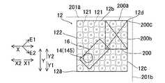
また、図5および図7に示すように、ロボットハンド12は、パレット201に配置されたワーク200を気体(空気)による吸引力により保持するための複数の吸着部121と、吸着部121が取り付けられるロボットハンド本体部122とを含む。また、ロボットハンド12の複数の吸着部121には、それぞれ、空気を吸引するための管(図示せず)が個別に接続されており、管から空気が吸い出されることにより、吸着部121をワーク200に吸着(保持)させるように構成されている。なお、吸着部121は、PLC5に接続(図2参照)されており、吸着部121の空気の吸引の動作のオンオフ(作動状態および非作動状態の切り替え)は、PLC5を介してPC6により制御される。ここで、本実施形態では、図7に示すように、複数の吸着部121は、平面視において、ロボットハンド12(ロボットハンド本体部122)の表面上に略均等に配置されている。具体的には、複数の吸着部121は、ロボットハンド本体部122の表面上に41個設けられており、41個の吸着部121が、ロボットハンド本体部122の表面上に千鳥格子状に設けられている。また、41個の吸着部121は、略正方形形状のロボットハンド本体部122の辺に沿って、5個、4個、5個、4個、5個、4個、5個、4個、5個ずつ配置されている。また、41個の吸着部121の個々の作動状態および非作動状態が、PC6により独立して切り替え可能に制御されるように構成されている。なお、吸着部121は、「保持部分」の一例である。 As shown in FIGS. 5 and 7, the
そして、本実施形態では、図8および図9に示すように、ワーク200の形状(矩形形状など)または大きさ(平面視におけるワーク200の面積など)に対応して複数の吸着部121の作動状態および非作動状態を切り替えた状態で、ワーク200を保持するようにPC6により制御されるように構成されている。具体的には、平面視において、ワーク200とロボットハンド12とがオーバーラップした部分に配置される吸着部121を作動状態にするとともに、その他の吸着部121を非作動状態にした状態で、ワーク200を保持するようにPC6に制御されるように構成されている。なお、吸着部121がワーク200に部分的にオーバーラップする場合には、作動状態にするようにしてもよいし、非作動状態にするようにしてもよい。また、所定の面積以上吸着部121がワーク200にオーバーラップしている場合に、作動状態にするようにしてもよい。 In this embodiment, as shown in FIGS. 8 and 9, the operation of the plurality of
また、本実施形態では、ロボット2に設けられるカメラ8により撮影されたワーク200の画像に基づいて、ワーク200とロボットハンド12とがオーバーラップする部分に配置される吸着部121を作動状態にするとともに、その他の吸着部121を非作動状態にした状態で、ワーク200を保持するようにPC6により制御されるように構成されている。また、図8に示すように、平面視において、ワーク200の大きさがロボットハンド12よりも小さい場合、ワーク200とロボットハンド12とがオーバーラップする部分に配置される吸着部121が作動状態にされる。また、平面視において、ワーク200の大きさがロボットハンド12の大きさ以上の場合、全ての吸着部121が作動状態にされる。また、ワーク200を保持し始めてから、ワーク200がコンベア202に載置されるまで、ワーク200とロボットハンド12とがオーバーラップする部分に配置される吸着部121が作動状態にされる。 Moreover, in this embodiment, based on the image of the workpiece | work 200 image | photographed with the
また、図8に示すように、ワーク200の辺200aおよび200bがパレット201の2つの辺201aおよび201bに略平行になるように配置されている場合には、平面視において、ロボットハンド12の先端側の互いに直交する2つの辺12bおよび12c(外縁)と、ワーク200の辺200aおよび200bとが重なるように、かつ、ロボットハンド12の先端側の角部12dとワーク200の角部200cとが重なるように、ロボットアーム14によりロボットハンド12が移動(回動)された状態で、ワーク200が保持される。なお、ワーク200がパレット201の隅部近傍に配置されている場合でも、中央部近傍に配置されている場合でも、ロボットハンド12の2つの辺12bおよび12c(外縁)と、ワーク200の4つの辺のうちの2つの辺とが重なるように、かつ、ロボットハンド12の先端側の角部12dとワーク200の4つの角部のうちの1つの角部とが重なる状態で、ワーク200が保持される。 As shown in FIG. 8, when the
また、図9に示すように、ワーク200の4つの辺がパレット201の2つの辺201aおよび201bに交差する状態で配置されている場合には、平面視において、ロボットハンド12の先端側の互いに直交する2つの辺12bおよび12c(外縁)と、ワーク200の2つの角部200cおよび200dとが重なるように、ロボットアーム14によりロボットハンド12が移動(回動)された状態で、ワーク200が保持される。 Further, as shown in FIG. 9, when the four sides of the
また、図10〜図13に示すように、ロボットアーム14が延びる方向であるX方向と交差する方向(E1方向、E2方向)に吸着部121の先端側が向くようにロボットアーム14により吸着部121を回動させた状態で、吸着部121によりパレット201に配置されたワーク200を保持するようにPC6により制御されるように構成されている。 As shown in FIGS. 10 to 13, the
また、図14に示すように、ロボット2は、ロボット本体21と、ロボット本体21の先端に取り付けられるロボットハンド22とを含む。また、ロボット本体21は、基台23およびロボットアーム24を有している。 As shown in FIG. 14, the
基台23は、フロア・壁・天井等の設置面に固定されている。ロボットアーム24は、6自由度を有して構成されている。ロボットアーム24は、複数のアーム構造体を有しており、設置面に対して垂直な回転軸B1まわりにアーム構造体241が基台23に対して回転可能に連結されている。アーム構造体242は、回転軸B1に対して垂直な回転軸B2まわりに回転可能にアーム構造体241に連結されている。アーム構造体243は、回転軸B2に対して平行な回転軸B3まわりに回転可能にアーム構造体242に連結されている。アーム構造体244は、回転軸B3に対して垂直な回転軸B4まわりに回転可能にアーム構造体243に連結されている。アーム構造体245は、回転軸B4に対して垂直な回転軸B5まわりに回転可能にアーム構造体244に連結されている。アーム構造体246は、回転軸B5に対して垂直な回転軸B6まわりに回転可能にアーム構造体245に連結されている。なお、ここでいう「平行」「垂直」は、必ずしも厳密に定義されるものではなく、実質的なものであればよい。各回転軸B1〜B6にはそれぞれサーボモータが設けられており、各サーボモータは、それぞれの回転位置を検出するエンコーダを有している。各サーボモータはロボットコントローラ4に接続されており、ロボットコントローラ4の指令に基づいて各サーボモータが動作するように構成されている。 The
また、図15に示すように、ロボットハンド22には、ワーク200に向かってレーザ光を照射するレーザ光照射部7と、ワーク200から反射されるレーザ光を検出するためのカメラ8(ステレオカメラ)とが取り付けられている。なお、レーザ光照射部7は、「検出部」の一例である。また、カメラ8は、「検出部」および「撮像部」の一例である。そして、レーザ光照射部7によりワーク200に向かってレーザ光をたとえば十字状に(交差するように)照射するとともに、カメラ8によりワーク200から反射されるレーザ光が検出(撮影)される。そして、検出結果(撮影された画像)に基づいて、ワーク200の配置状態(ワーク200の高さ(ワーク200の上面の高さ位置)、回転角度、位置、形状、大きさ等)がPC6により算出(計測)されるように構成されている。そして、本実施形態では、レーザ光照射部7およびカメラ8により検出されたワーク200の配置状態に基づいてロボットアーム14を移動させて、ロボットハンド12によりパレット201に配置されたワーク200を保持するようにPC6により制御されるように構成されている。 Further, as shown in FIG. 15, the
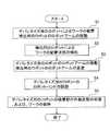
次に、図16〜図18を参照して、本実施形態によるロボットシステム100の動作について説明する。 Next, the operation of the
まず、図16に示すように、ステップS1において、レーザ光照射部7およびカメラ8による前回の検出動作によって検出されたパレット201の最上段に配置されるワーク200の配置状態に基づいて、図17に示すように、ロボットアーム14のロボットハンド12により、ワーク200が保持されるとともに、ロボットアーム14が移動されることにより、ワーク200がコンベア202に載置される。 First, as shown in FIG. 16, based on the arrangement state of the
また、ロボットアーム14によるワーク200の載置動作と並行して(または、ワーク200の搬送動作と並行して)、ロボットアーム24が移動されることにより、ロボットアーム24に取り付けられているロボットハンド22(レーザ光照射部7およびカメラ8)がパレット201の上方に配置される。 The robot arm attached to the
そして、ステップS2において、レーザ光照射部7によりワーク200に向かってレーザ光が照射されるとともに、カメラ8によりワーク200から反射されるレーザ光が撮影されて、パレット201に配置された次に保持するワーク200の配置状態(高さ、形状、大きさなど)が検出される。そして、検出された複数のワーク200のうち、保持対象となるワーク200(たとえば、最上段のワーク200)が選択される。なお、このとき、後述するステップS5における作動状態にする吸着部121と、非作動状態にする吸着部121とが選択される。 In step S <b> 2, laser light is irradiated toward the
次に、ステップS3において、図18に示すように、ロボットアーム14がパレット201の上方へ移動される。そして、ロボットアーム14の移動動作と並行して、ロボットアーム24が、ロボットアーム14に衝突するのを避けるようにパレット201の近傍からパレット201から離れる方向に退避される。 Next, in step S3, the
次に、ステップS4において、たとえば、X方向と直交するY2方向側(Y1方向側)に配置されるワーク200を保持する場合には、基準状態(図4参照)から、図10および図11(図12および図13)に示すように、Y2方向側(Y1方向側)にロボットアーム14によりロボットハンド12を略45度回動させた後、保持対象となるワーク200の上方にロボットハンド12が移動される。そして、ステップS5において、平面視において、ワーク200とロボットハンド12とがオーバーラップした部分に配置される吸着部121を作動状態にするとともに、その他の吸着部121を非作動状態にした状態で、ワーク200が保持される。その後、ステップS1に戻って、ワーク200がコンベア202に載置される。また、ワーク200がコンベア202に載置された後、全ての吸着部121が非作動状態にされる。 Next, in step S4, for example, when holding the
そして、ステップS1〜S5の動作が、パレット201からワーク200が無くなるまで繰り返されて、ロボットハンド12によるワーク200のデパレタイズが終了される。 Then, the operations in steps S1 to S5 are repeated until the
本実施形態では、上記のように、ワーク200の形状または大きさに対応して複数の吸着部121の作動状態および非作動状態を切り替えた状態で、ワーク200を保持するように制御するPC6を備えることによって、ワーク200の形状または大きさに合わせて複数の吸着部121を作動状態にすることができるので、形状や大きさがワーク200によって異なっている場合でもワーク200を保持することができる。 In the present embodiment, as described above, the
また、本実施形態では、上記のように、平面視において、ワーク200とロボットハンド12とがオーバーラップした部分に配置される吸着部121を作動状態にするとともに、その他の吸着部121を非作動状態にした状態で、ワーク200を保持するように制御するようにPC6を構成する。これにより、作動状態にする複数の吸着部121を、容易にワーク200の形状または大きさに合わせることができるので、形状や大きさがワーク200によって異なっている場合でもワーク200を容易に保持することができる。また、ロボットシステム100の空気の吸引量に上限がある場合には、ワーク200とロボットハンド12とがオーバーラップしない部分に配置される吸着部121を非作動状態にすることにより、その分、作動状態にされる吸着部121の吸引量を多くして、吸着部121の吸引力を強くすることができる。 Further, in the present embodiment, as described above, in the plan view, the
また、本実施形態では、上記のように、パレット201に配置されたワーク200の形状または大きさを検出するレーザ光照射部7およびカメラ8を設けて、PC6を、レーザ光照射部7およびカメラ8により検出されたワーク200の形状または大きさに対応して複数の吸着部121の作動状態および非作動状態を切り替えた状態で、ワーク200を保持するように制御するように構成する。これにより、ワーク200の形状または大きさがレーザ光照射部7およびカメラ8により検出されるので、ワーク200の形状または大きさに対応して複数の吸着部121の作動状態および非作動状態を容易に切り替えることができる。 In the present embodiment, as described above, the laser
また、本実施形態では、上記のように、PC6を、カメラ8により撮像されたワーク200の画像に基づいて、ワーク200とロボットハンド12とがオーバーラップする部分に配置される吸着部121を作動状態にするとともに、その他の吸着部121を非作動状態にした状態で、ワーク200を保持するように制御するように構成する。これにより、カメラ8により撮像されたワーク200の画像に基づいて、容易に、ワーク200の形状または大きさを検出することができる。 In the present embodiment, as described above, the
また、本実施形態では、上記のように、PC6を、複数の吸着部121の個々の作動状態および非作動状態を独立して切り替え可能に制御するように構成する。これにより、容易に、ワーク200の形状または大きさに合わせて複数の吸着部121を作動状態または非作動状態にすることができる。 In the present embodiment, as described above, the
また、本実施形態では、上記のように、ロボットハンド12の先端側の互いに直交する2つの辺とパレット201の2つの辺とが略平行になるように、ロボットハンド12を回動させた状態で、かつ、ワーク200の形状に対応して複数の吸着部121の作動状態および非作動状態を切り替えた状態で、ロボットハンド12によりワーク200を保持するように制御するようにPC6を構成する。これにより、略矩形形状を有するパレット201の隅部に略矩形形状のワーク200が配置されている場合でも、ワーク200の外縁に沿ってロボットハンド12の外縁を配置することができるので、ワーク200とロボットハンド12とをオーバーラップさせた状態で、ワーク200を保持することができる。 In the present embodiment, as described above, the
また、本実施形態では、上記のように、複数の吸着部121を、平面視において、ロボットハンド12の表面上に略均等に配置する。これにより、複数の吸着部121がロボットハンド12の表面上に偏って配置されている場合と異なり、ロボットハンド12のいずれの位置でワーク200を保持する場合でも、ワーク200と吸着部121とをオーバーラップさせた状態で、ワーク200を確実に保持することができる。 Further, in the present embodiment, as described above, the plurality of
なお、今回開示された実施形態は、すべての点で例示であって制限的なものではないと考えられるべきである。本発明の範囲は、上記した実施形態の説明ではなく特許請求の範囲によって示され、さらに特許請求の範囲と均等の意味および範囲内でのすべての変更が含まれる。 The embodiment disclosed this time should be considered as illustrative in all points and not restrictive. The scope of the present invention is shown not by the above description of the embodiments but by the scope of claims for patent, and further includes all modifications within the meaning and scope equivalent to the scope of claims for patent.
たとえば、上記実施形態では、5自由度を有するデパレタイズ用のロボットおよび6自由度を有する検出用のロボットの2台のロボットを用いて、パレットに配置されたワークの配置状態の検出、保持および搬送を行う例を示したが、1台の双腕ロボットを用いて、パレットに配置されたワークの配置状態の検出、保持および搬送を行うようにしてもよい。また、デパレタイズ用のロボット、検出用のロボットの制御軸の数も適宜選択可能であり、それぞれ4自由度のロボットアームを用いてもよく、4自由度よりも多くの自由度を有するロボットアームを用いてもよい。 For example, in the above-described embodiment, detection, holding, and conveyance of a workpiece arranged on a pallet are performed using two robots, a depalletizing robot having five degrees of freedom and a detection robot having six degrees of freedom. Although an example of performing the above is shown, it is also possible to detect, hold and transport the arrangement state of the workpieces arranged on the pallet using a single double-arm robot. In addition, the number of control axes of the depalletizing robot and the detecting robot can be selected as appropriate, and a robot arm having four degrees of freedom may be used, or a robot arm having more degrees of freedom than four degrees of freedom. It may be used.
また、上記実施形態では、空気による吸引力によりワークを保持する例を示したが、たとえば、電磁(磁石)による吸引力(磁力)によりワークを保持してもよい。 Moreover, although the example which hold | maintains a workpiece | work with the attraction | suction force by air was shown in the said embodiment, you may hold | maintain a workpiece | work with the attraction | suction force (magnetic force) by electromagnetic (magnet), for example.
また、上記実施形態では、ロボットハンドに吸着部が41個設けられる例を示したが、たとえば、41個以外の数の吸着部をロボットハンドに設けてもよい。 Moreover, although the example which provided 41 adsorption | suction parts in the robot hand was shown in the said embodiment, for example, you may provide a number of adsorption | suction parts other than 41 in a robot hand.
また、上記実施形態では、平面視において、ワークとロボットハンドとがオーバーラップした部分に配置される吸着部を作動状態にするとともに、その他の吸着部を非作動状態にした状態で、ワークを保持する例を示したが、たとえば、ワークとロボットハンドとがオーバーラップした部分に配置される吸着部の一部を非作動状態にしてもよい。 In the above-described embodiment, the workpiece is held in a state in which the suction portion disposed in the overlapped portion of the workpiece and the robot hand is in the activated state and the other suction portions are in the non-activated state in plan view. Although the example to do was shown, for example, you may make a part of adsorption | suction part arrange | positioned in the part which the workpiece | work and the robot hand overlapped into a non-operation state.
また、上記実施形態では、ワークを保持し始めてから、ワークがコンベアに載置されるまで、ワークとロボットハンドとがオーバーラップする部分に配置される吸着部が作動状態にされる例を示したが、たとえば、ワークを保持し始める際には、ワークとロボットハンドとがオーバーラップした部分に配置される吸着部の一部(ワークの外縁近傍に配置される吸着部)を非作動状態にするとともに、その後、ワークとロボットハンドとがオーバーラップする部分に配置される吸着部の全てを作動状態にしてもよい。これにより、保持対象となるワークに隣接するワークが誤って保持されるのを抑制することができる。 Moreover, in the said embodiment, from the time it started holding a workpiece | work, until the workpiece | work was mounted on the conveyor, the example which the adsorption | suction part arrange | positioned in the part which a workpiece | work and a robot hand overlap is shown in the operation state was shown. However, when starting to hold the workpiece, for example, a part of the suction portion (the suction portion arranged near the outer edge of the workpiece) arranged in the portion where the workpiece and the robot hand overlap with each other is deactivated. At the same time, all of the suction portions arranged in the portion where the workpiece and the robot hand overlap may be put into an operating state. Thereby, it can suppress that the workpiece | work adjacent to the workpiece | work used as holding | maintenance object is hold | maintained accidentally.
また、上記実施形態では、レーザ光照射部およびカメラにより検出されたワークの形状または大きさに対応して複数の吸着部の作動状態および非作動状態を切り替える例を示したが、たとえば、予めワークの形状または大きさが既知である場合には、レーザ光照射部およびカメラを設けずに予め既知のワークの形状または大きさに基づいて、複数の吸着部の作動状態および非作動状態を切り替えてもよい。 In the above embodiment, an example in which the operation state and the non-operation state of the plurality of suction units are switched in accordance with the shape or size of the workpiece detected by the laser beam irradiation unit and the camera has been described. If the shape or size of the suction unit is already known, the operation state and non-operation state of the plurality of suction units are switched based on the known shape or size of the workpiece in advance without providing the laser beam irradiation unit and the camera. Also good.
また、上記実施形態では、複数の吸着部の個々の作動状態および非作動状態を独立して切り替え可能に構成する例を示したが、たとえば、所定の数の吸着部毎(たとえば、4つの吸着部毎など)に作動状態および非作動状態を切り替えるように構成してもよい。これにより、複数の吸着部の切り替えの制御を簡略化することができる。 In the above-described embodiment, an example in which individual operation states and non-operation states of a plurality of adsorption units can be switched independently has been described. For example, for each predetermined number of adsorption units (for example, four adsorption units) You may comprise so that an operation state and a non-operation state may be switched for every part etc.). Thereby, control of switching of a plurality of adsorption parts can be simplified.
また、上記実施形態では、複数の吸着部がロボットハンドの表面上に千鳥格子状に配置されている例を示したが、たとえば、複数の吸着部をマトリクス状に配置してもよい。 In the above-described embodiment, an example in which a plurality of suction units are arranged in a staggered pattern on the surface of the robot hand has been described. For example, a plurality of suction units may be arranged in a matrix.
また、上記実施形態では、ロボットハンドの先端側でワークを保持する例を示したが、たとえば、ロボットハンドの中央部側で、ワークを保持してもよい。 Moreover, although the example which hold | maintains a workpiece | work on the front end side of a robot hand was shown in the said embodiment, you may hold | maintain a workpiece | work on the center part side of a robot hand, for example.
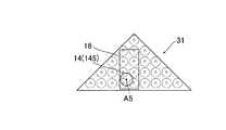
また、上記実施形態では、ロボットハンドが、平面視において、略正方形形状を有している例を示したが、たとえば、図19に示す第1変形例によるロボットハンド31のように、ロボットハンド31が、先端側に互いに直交する2つの辺を有する略三角形形状を有していてもよい。また、図20に示す第2変形例によるロボットハンド32のように、ロボットハンド32が、先端側に互いに直交する2つの辺を有する略五角形形状を有していてもよい。また、ロボットハンドが、略正方形形状などの多角形形状以外の形状(楕円形形状など)を有していてもよい。これらの変形例の場合でも、ワークとロボットハンドとがオーバーラップした部分に配置される吸着部が作動状態にされるとともに、その他の吸着部が非作動状態にされる。 Moreover, in the said embodiment, although the robot hand showed the example which has substantially square shape in planar view, for example, the
また、上記実施形態では、パレットに積み上げられたワークをロボットシステムによりデパレタイズする例を示したが、たとえば、ロボットシステムに、パレタイズなどのデパレタイズ以外の作業を行わせてもよい。 Moreover, although the example which depalletizes the workpiece | work piled up on the pallet with the robot system was shown in the said embodiment, for example, you may make a robot system perform work other than depalletizing, such as palletizing.
また、上記実施形態では、PCによりロボット(ロボットシステム)の動作を制御する例を示したが、たとえば、PLCやロボットコントローラによりロボットの動作を制御してもよい。 Moreover, although the example which controls operation | movement of a robot (robot system) by PC was shown in the said embodiment, you may control operation | movement of a robot by PLC and a robot controller, for example.
6 PC(ロボット制御部)
7 レーザ光照射部(検出部)
8 カメラ(検出部、撮像部)
12、31、32 ロボットハンド
12b、12c 辺
100 ロボットシステム
121 吸着部(保持部分)
200 ワーク
201 パレット(ワーク配置部)
201a、201b 辺6 PC (robot controller)
7 Laser beam irradiation part (detection part)
8 Camera (detection unit, imaging unit)
12, 31, 32
200
201a, 201b side
Claims (8)
Translated fromJapanese前記ワークの形状または大きさに対応して前記複数の保持部分の作動状態および非作動状態を切り替えた状態で、前記ワークを保持するように制御するロボット制御部とを備える、ロボットシステム。A robot hand provided with a plurality of holding portions for holding a work placed in the work placement portion by an electromagnetic or gas suction force;
A robot system comprising: a robot control unit that controls to hold the workpiece in a state in which an operation state and a non-operation state of the plurality of holding portions are switched corresponding to the shape or size of the workpiece.
前記ロボット制御部は、前記検出部により検出された前記ワークの形状または大きさに対応して前記複数の保持部分の作動状態および非作動状態を切り替えた状態で、前記ワークを保持するように制御するように構成されている、請求項1または2に記載のロボットシステム。A detection unit that detects the shape or size of the workpiece arranged in the workpiece arrangement unit;
The robot control unit is controlled to hold the workpiece in a state where the operation state and the non-operation state of the plurality of holding portions are switched corresponding to the shape or size of the workpiece detected by the detection unit. The robot system according to claim 1, wherein the robot system is configured to.
前記ロボット制御部は、前記撮像部により撮像された前記ワークの画像に基づいて、前記ワークと前記ロボットハンドとがオーバーラップする部分に配置される保持部分を作動状態にするとともに、その他の保持部分を非作動状態にした状態で、前記ワークを保持するように制御するように構成されている、請求項3に記載のロボットシステム。The detection unit includes an imaging unit that images the workpiece placed in the workpiece placement unit,
The robot control unit activates a holding portion arranged in a portion where the workpiece and the robot hand overlap based on an image of the workpiece imaged by the imaging unit, and other holding portions. The robot system according to claim 3, wherein the robot system is configured to control to hold the workpiece in a non-operating state.
前記ロボットハンドは、平面視において、前記先端側に互いに略直交する2つの辺を有する形状を有しており、
前記ロボット制御部は、前記ロボットハンドの先端側の互いに直交する2つの辺と前記ワーク配置部の2つの辺とが略平行になるように、前記ロボットハンドを回動させた状態で、かつ、前記ワークの形状に対応して前記複数の保持部分の作動状態および非作動状態を切り替えた状態で、前記ロボットハンドにより前記ワークを保持するように制御するように構成されている、請求項1〜5のいずれか1項に記載のロボットシステム。The work placement portion has a substantially rectangular shape so as to surround the work in a plan view,
The robot hand has a shape having two sides substantially orthogonal to each other on the tip side in a plan view,
The robot control unit is in a state in which the robot hand is rotated so that two orthogonal sides on the tip side of the robot hand and two sides of the work placement unit are substantially parallel, and The control unit is configured to control to hold the workpiece by the robot hand in a state in which an operation state and a non-operation state of the plurality of holding portions are switched corresponding to the shape of the workpiece. 6. The robot system according to any one of 5 above.
前記複数の保持部分の作動状態および非作動状態を切り替えた状態で、前記ワークを保持する工程とを備える、ワークの搬送方法。In accordance with the shape or size of the workpiece, the operation state and the non-operation state of a plurality of holding portions provided in the robot hand for holding the workpiece arranged in the workpiece arrangement unit by electromagnetic or gas suction force are switched. Process,
And a step of holding the workpiece in a state where the operating state and the non-operating state of the plurality of holding portions are switched.
Priority Applications (4)
| Application Number | Priority Date | Filing Date | Title |
|---|---|---|---|
| JP2013052167AJP2014176926A (en) | 2013-03-14 | 2013-03-14 | Robot system and method for conveying work |
| CN201410006635.2ACN104044151A (en) | 2013-03-14 | 2014-01-07 | Robot system and method for transferring workpiece |
| EP14157417.8AEP2783801A3 (en) | 2013-03-14 | 2014-03-03 | Robot system and method for transferring workpiece |
| US14/210,446US20140277721A1 (en) | 2013-03-14 | 2014-03-14 | Robot system and method for transferring workpiece |
Applications Claiming Priority (1)
| Application Number | Priority Date | Filing Date | Title |
|---|---|---|---|
| JP2013052167AJP2014176926A (en) | 2013-03-14 | 2013-03-14 | Robot system and method for conveying work |
Publications (1)
| Publication Number | Publication Date |
|---|---|
| JP2014176926Atrue JP2014176926A (en) | 2014-09-25 |
Family
ID=50189584
Family Applications (1)
| Application Number | Title | Priority Date | Filing Date |
|---|---|---|---|
| JP2013052167APendingJP2014176926A (en) | 2013-03-14 | 2013-03-14 | Robot system and method for conveying work |
Country Status (4)
| Country | Link |
|---|---|
| US (1) | US20140277721A1 (en) |
| EP (1) | EP2783801A3 (en) |
| JP (1) | JP2014176926A (en) |
| CN (1) | CN104044151A (en) |
Cited By (16)
| Publication number | Priority date | Publication date | Assignee | Title |
|---|---|---|---|---|
| CN104723325A (en)* | 2015-03-17 | 2015-06-24 | 南京理工大学 | Feeding manipulator for automatic production line |
| JP2017520433A (en)* | 2015-04-14 | 2017-07-27 | ヴェーエムイー ホーランド ベー. ヴェー.Vmi Holland B. V. | Gripper assembly and method for gripping tire components |
| JP2019162685A (en)* | 2018-03-19 | 2019-09-26 | 株式会社東芝 | Holding device, carrier system, controller and holding method |
| JP2020163479A (en)* | 2019-03-28 | 2020-10-08 | 株式会社Ihi | De-palletize apparatus and de-palletize method |
| KR102169074B1 (en)* | 2020-03-19 | 2020-10-22 | 주식회사 에이스로보테크 | Robot for connecting rod transfer using electromagnet |
| JP2021030431A (en)* | 2019-08-21 | 2021-03-01 | 株式会社Mujin | Robotic multi-gripper assemblies and methods for gripping and holding objects |
| JP2021088054A (en)* | 2019-12-05 | 2021-06-10 | 所羅門股▲分▼有限公司 | Article extraction system and article extraction method |
| JP2021122872A (en)* | 2020-02-03 | 2021-08-30 | 株式会社デンソーウェーブ | Work-piece adsorber |
| US11117256B2 (en) | 2019-08-21 | 2021-09-14 | Mujin, Inc. | Robotic multi-gripper assemblies and methods for gripping and holding objects |
| JP2021146477A (en)* | 2020-03-23 | 2021-09-27 | Kyoto Robotics株式会社 | Robot hand |
| US11186445B2 (en) | 2017-11-02 | 2021-11-30 | Kabushiki Kaisha Toshiba | Picking system |
| US11365065B2 (en) | 2018-02-19 | 2022-06-21 | Kabushiki Kaisha Toshiba | Conveyor system and conveying method |
| US11969883B2 (en) | 2020-08-05 | 2024-04-30 | Ryoei Co., Ltd. | Handling method and apparatus for stacked box |
| US12037206B2 (en) | 2018-06-18 | 2024-07-16 | Kabushiki Kaisha Toshiba | Cargo-handling apparatus and program |
| JP7580720B2 (en) | 2021-04-08 | 2024-11-12 | リョーエイ株式会社 | Method and device for handling returnable boxes with lids |
| WO2024247134A1 (en)* | 2023-05-30 | 2024-12-05 | 川崎重工業株式会社 | Control device, robot system, and robot control method |
Families Citing this family (21)
| Publication number | Priority date | Publication date | Assignee | Title |
|---|---|---|---|---|
| US9205558B1 (en)* | 2014-07-16 | 2015-12-08 | Google Inc. | Multiple suction cup control |
| JP6486114B2 (en)* | 2015-01-16 | 2019-03-20 | 株式会社東芝 | Handling equipment |
| JP6034892B2 (en)* | 2015-01-27 | 2016-11-30 | ファナック株式会社 | A robot system in which the brightness of the robot mount changes |
| CN104760826B (en)* | 2015-04-13 | 2017-12-19 | 上海金东唐科技有限公司 | Automatic fine tuning test equipment |
| JP6407927B2 (en)* | 2015-11-12 | 2018-10-17 | 株式会社東芝 | Conveying device, conveying system, conveying method, control device, and program |
| CN105522565A (en)* | 2016-01-26 | 2016-04-27 | 中塑联新材料科技湖北有限公司 | Mechanical arm for stacking plastic plates or plastic sheets |
| US10221015B2 (en)* | 2016-06-27 | 2019-03-05 | Amazon Technologies, Inc. | Automated item singulation |
| JP2018122945A (en)* | 2017-01-30 | 2018-08-09 | 株式会社東芝 | Variable article holding device, transfer device, robot handling system, and control method of transfer device |
| NL2018380B1 (en)* | 2017-02-15 | 2018-09-06 | Vmi Holland Bv | Transfer device and method for transferring a tire component |
| CN106829462A (en)* | 2017-03-07 | 2017-06-13 | 河南摩西机械制造有限公司 | A kind of iron pan conveying robot |
| JP2018203480A (en)* | 2017-06-07 | 2018-12-27 | 株式会社東芝 | Sorting apparatus and sorting system |
| CN107253227A (en)* | 2017-07-25 | 2017-10-17 | 广州锦湖自动化设备有限公司 | Automatic shearing eyeglass machine |
| JP6937260B2 (en)* | 2018-03-19 | 2021-09-22 | 株式会社東芝 | Grip control device, grip system, and program |
| DE102018208126A1 (en)* | 2018-05-23 | 2019-11-28 | Trumpf Werkzeugmaschinen Gmbh + Co. Kg | Method for handling a workpiece with the aid of a removal tool and machine for carrying out the method |
| JP7141288B2 (en)* | 2018-09-25 | 2022-09-22 | 川崎重工業株式会社 | robot system |
| US10335947B1 (en) | 2019-01-18 | 2019-07-02 | Mujin, Inc. | Robotic system with piece-loss management mechanism |
| JP6958593B2 (en)* | 2019-05-29 | 2021-11-02 | 村田機械株式会社 | Transfer device |
| CN111993448B (en)* | 2019-08-21 | 2022-02-08 | 牧今科技 | Robotic multi-gripper assembly and method for gripping and holding objects |
| KR20220054402A (en) | 2019-09-04 | 2022-05-02 | 더 스틸래스틱 캄파니 엘.엘.씨. | Transport tooling to change tire belt size |
| JP7123885B2 (en)* | 2019-09-13 | 2022-08-23 | 株式会社東芝 | Handling device, control device and holding method |
| CN114311007A (en)* | 2022-01-14 | 2022-04-12 | 上海交通大学 | Flexible electromagnet gripper for grabbing steel plate |
Citations (11)
| Publication number | Priority date | Publication date | Assignee | Title |
|---|---|---|---|---|
| JPS59152089A (en)* | 1983-02-16 | 1984-08-30 | 株式会社ブリヂストン | Hand for industrial robot |
| JPS61214989A (en)* | 1985-03-15 | 1986-09-24 | 三菱電機株式会社 | Industrial robot hand device |
| JPH0411609U (en)* | 1990-05-18 | 1992-01-30 | ||
| JPH0471210U (en)* | 1990-10-31 | 1992-06-24 | ||
| JPH09160618A (en)* | 1995-12-11 | 1997-06-20 | Ricoh Co Ltd | Coordinate correction device for horizontal articulated robot |
| JPH09285986A (en)* | 1996-04-23 | 1997-11-04 | Ricoh Co Ltd | End effector |
| JPH10120354A (en)* | 1996-10-21 | 1998-05-12 | Amada Co Ltd | Selective operating system of vacuum pad for plate work |
| JP2000127074A (en)* | 1998-10-23 | 2000-05-09 | Tsubakimoto Chain Co | Grasping device |
| JP2006007409A (en)* | 2004-05-21 | 2006-01-12 | Fanuc Ltd | Structure for treating cable element in industrial robot |
| JP2009083037A (en)* | 2007-09-28 | 2009-04-23 | Yushin Precision Equipment Co Ltd | Gripping tool |
| JP2010005769A (en)* | 2008-06-30 | 2010-01-14 | Ihi Corp | Depalletizing apparatus and depalletizing method |
Family Cites Families (3)
| Publication number | Priority date | Publication date | Assignee | Title |
|---|---|---|---|---|
| JP3482938B2 (en) | 2000-05-02 | 2004-01-06 | 株式会社ダイフク | Article position recognition device |
| KR100456858B1 (en)* | 2002-12-18 | 2004-11-10 | 현대자동차주식회사 | A vertical shaft adjusting apparatus by multi steps at an attachment |
| TW201114525A (en)* | 2009-10-30 | 2011-05-01 | Sun Yueh Way | Method for cutting a liquid crystal display cell mother board and automatic cutting system for the same |
- 2013
- 2013-03-14JPJP2013052167Apatent/JP2014176926A/enactivePending
- 2014
- 2014-01-07CNCN201410006635.2Apatent/CN104044151A/enactivePending
- 2014-03-03EPEP14157417.8Apatent/EP2783801A3/ennot_activeWithdrawn
- 2014-03-14USUS14/210,446patent/US20140277721A1/ennot_activeAbandoned
Patent Citations (11)
| Publication number | Priority date | Publication date | Assignee | Title |
|---|---|---|---|---|
| JPS59152089A (en)* | 1983-02-16 | 1984-08-30 | 株式会社ブリヂストン | Hand for industrial robot |
| JPS61214989A (en)* | 1985-03-15 | 1986-09-24 | 三菱電機株式会社 | Industrial robot hand device |
| JPH0411609U (en)* | 1990-05-18 | 1992-01-30 | ||
| JPH0471210U (en)* | 1990-10-31 | 1992-06-24 | ||
| JPH09160618A (en)* | 1995-12-11 | 1997-06-20 | Ricoh Co Ltd | Coordinate correction device for horizontal articulated robot |
| JPH09285986A (en)* | 1996-04-23 | 1997-11-04 | Ricoh Co Ltd | End effector |
| JPH10120354A (en)* | 1996-10-21 | 1998-05-12 | Amada Co Ltd | Selective operating system of vacuum pad for plate work |
| JP2000127074A (en)* | 1998-10-23 | 2000-05-09 | Tsubakimoto Chain Co | Grasping device |
| JP2006007409A (en)* | 2004-05-21 | 2006-01-12 | Fanuc Ltd | Structure for treating cable element in industrial robot |
| JP2009083037A (en)* | 2007-09-28 | 2009-04-23 | Yushin Precision Equipment Co Ltd | Gripping tool |
| JP2010005769A (en)* | 2008-06-30 | 2010-01-14 | Ihi Corp | Depalletizing apparatus and depalletizing method |
Cited By (29)
| Publication number | Priority date | Publication date | Assignee | Title |
|---|---|---|---|---|
| CN104723325B (en)* | 2015-03-17 | 2016-04-20 | 南京理工大学 | A feeding manipulator for automatic production line |
| CN104723325A (en)* | 2015-03-17 | 2015-06-24 | 南京理工大学 | Feeding manipulator for automatic production line |
| JP2017520433A (en)* | 2015-04-14 | 2017-07-27 | ヴェーエムイー ホーランド ベー. ヴェー.Vmi Holland B. V. | Gripper assembly and method for gripping tire components |
| US10232516B2 (en) | 2015-04-14 | 2019-03-19 | Vmi Holland B.V. | Gripper assembly and method for gripping a tire component |
| US11186445B2 (en) | 2017-11-02 | 2021-11-30 | Kabushiki Kaisha Toshiba | Picking system |
| US11365065B2 (en) | 2018-02-19 | 2022-06-21 | Kabushiki Kaisha Toshiba | Conveyor system and conveying method |
| JP2019162685A (en)* | 2018-03-19 | 2019-09-26 | 株式会社東芝 | Holding device, carrier system, controller and holding method |
| JP7000213B2 (en) | 2018-03-19 | 2022-01-19 | 株式会社東芝 | Retention device, transport system, controller, and retention method |
| US12037206B2 (en) | 2018-06-18 | 2024-07-16 | Kabushiki Kaisha Toshiba | Cargo-handling apparatus and program |
| JP2020163479A (en)* | 2019-03-28 | 2020-10-08 | 株式会社Ihi | De-palletize apparatus and de-palletize method |
| JP7211208B2 (en) | 2019-03-28 | 2023-01-24 | 株式会社Ihi | Depalletizing device and depalletizing method |
| JP2022009120A (en)* | 2019-08-21 | 2022-01-14 | 株式会社Mujin | Robot type multi gripper assembly and method for gripping and holding object |
| JP7498905B2 (en) | 2019-08-21 | 2024-06-13 | 株式会社Mujin | Robotic multi-gripper assembly and method for gripping and holding an object - Patents.com |
| US12296480B2 (en) | 2019-08-21 | 2025-05-13 | Mujin, Inc. | Robotic multi-gripper assemblies and methods for gripping and holding objects |
| US11117256B2 (en) | 2019-08-21 | 2021-09-14 | Mujin, Inc. | Robotic multi-gripper assemblies and methods for gripping and holding objects |
| US11958191B2 (en) | 2019-08-21 | 2024-04-16 | Mujin, Inc. | Robotic multi-gripper assemblies and methods for gripping and holding objects |
| US11345029B2 (en) | 2019-08-21 | 2022-05-31 | Mujin, Inc. | Robotic multi-gripper assemblies and methods for gripping and holding objects |
| US11904468B2 (en) | 2019-08-21 | 2024-02-20 | Mujin, Inc. | Robotic multi-gripper assemblies and methods for gripping and holding objects |
| JP2021030431A (en)* | 2019-08-21 | 2021-03-01 | 株式会社Mujin | Robotic multi-gripper assemblies and methods for gripping and holding objects |
| JP2021088054A (en)* | 2019-12-05 | 2021-06-10 | 所羅門股▲分▼有限公司 | Article extraction system and article extraction method |
| US11213958B2 (en) | 2019-12-05 | 2022-01-04 | Solomon Technology Corporation | Transferring system and method for transferring an object |
| JP7467951B2 (en) | 2020-02-03 | 2024-04-16 | 株式会社デンソーウェーブ | Workpiece suction device |
| JP2021122872A (en)* | 2020-02-03 | 2021-08-30 | 株式会社デンソーウェーブ | Work-piece adsorber |
| KR102169074B1 (en)* | 2020-03-19 | 2020-10-22 | 주식회사 에이스로보테크 | Robot for connecting rod transfer using electromagnet |
| JP7457546B2 (en) | 2020-03-23 | 2024-03-28 | 株式会社日立オートメーション | robot hand |
| JP2021146477A (en)* | 2020-03-23 | 2021-09-27 | Kyoto Robotics株式会社 | Robot hand |
| US11969883B2 (en) | 2020-08-05 | 2024-04-30 | Ryoei Co., Ltd. | Handling method and apparatus for stacked box |
| JP7580720B2 (en) | 2021-04-08 | 2024-11-12 | リョーエイ株式会社 | Method and device for handling returnable boxes with lids |
| WO2024247134A1 (en)* | 2023-05-30 | 2024-12-05 | 川崎重工業株式会社 | Control device, robot system, and robot control method |
Also Published As
| Publication number | Publication date |
|---|---|
| EP2783801A2 (en) | 2014-10-01 |
| CN104044151A (en) | 2014-09-17 |
| US20140277721A1 (en) | 2014-09-18 |
| EP2783801A3 (en) | 2015-03-04 |
Similar Documents
| Publication | Publication Date | Title |
|---|---|---|
| JP2014176926A (en) | Robot system and method for conveying work | |
| JP5768827B2 (en) | Robot system and workpiece transfer method | |
| JP6273084B2 (en) | Robot system and workpiece transfer method | |
| US11958187B2 (en) | Robot hand, robot and robot system | |
| US9102063B2 (en) | Robot apparatus | |
| KR101952767B1 (en) | Robot | |
| JP6468159B2 (en) | Transport system and transport method | |
| JP5535884B2 (en) | Work removal method | |
| CN103056884A (en) | Robot system and processed object manufacturing method | |
| JP5803887B2 (en) | robot | |
| JP6757646B2 (en) | Board gripping hand and board transfer device equipped with it | |
| TW202346039A (en) | Robotic system to load and unload trucks and other containers | |
| JP6766339B2 (en) | Robots and robot systems | |
| JP5895939B2 (en) | Handling system | |
| TWI705878B (en) | Robot system and its operating method | |
| JP2022148679A (en) | Transfer device and transfer method | |
| US20130133189A1 (en) | Robot system and method of manufacturing workpiece | |
| WO2025037441A1 (en) | Gripping device and method | |
| WO2024247134A1 (en) | Control device, robot system, and robot control method | |
| JP5921901B2 (en) | Robot controller | |
| JP2019076959A (en) | Article transfer device |
Legal Events
| Date | Code | Title | Description |
|---|---|---|---|
| A131 | Notification of reasons for refusal | Free format text:JAPANESE INTERMEDIATE CODE: A131 Effective date:20140902 | |
| A521 | Request for written amendment filed | Free format text:JAPANESE INTERMEDIATE CODE: A523 Effective date:20141029 | |
| A02 | Decision of refusal | Free format text:JAPANESE INTERMEDIATE CODE: A02 Effective date:20150303 | |
| A521 | Request for written amendment filed | Free format text:JAPANESE INTERMEDIATE CODE: A523 Effective date:20150603 | |
| A911 | Transfer to examiner for re-examination before appeal (zenchi) | Free format text:JAPANESE INTERMEDIATE CODE: A911 Effective date:20150616 | |
| A912 | Re-examination (zenchi) completed and case transferred to appeal board | Free format text:JAPANESE INTERMEDIATE CODE: A912 Effective date:20150807 |