JP2014176647A - Artificial intervertebral disk and insert plate - Google Patents
Artificial intervertebral disk and insert plateDownload PDFInfo
- Publication number
- JP2014176647A JP2014176647AJP2014047540AJP2014047540AJP2014176647AJP 2014176647 AJP2014176647 AJP 2014176647AJP 2014047540 AJP2014047540 AJP 2014047540AJP 2014047540 AJP2014047540 AJP 2014047540AJP 2014176647 AJP2014176647 AJP 2014176647A
- Authority
- JP
- Japan
- Prior art keywords
- disc
- flange
- insertion plate
- hole
- artificial
- Prior art date
- Legal status (The legal status is an assumption and is not a legal conclusion. Google has not performed a legal analysis and makes no representation as to the accuracy of the status listed.)
- Pending
Links
- 210000000988bone and boneAnatomy0.000claimsabstractdescription152
- 238000003780insertionMethods0.000claimsdescription337
- 230000037431insertionEffects0.000claimsdescription336
- 230000004927fusionEffects0.000claimsdescription22
- 230000008878couplingEffects0.000claimsdescription5
- 238000010168coupling processMethods0.000claimsdescription5
- 238000005859coupling reactionMethods0.000claimsdescription5
- 238000002513implantationMethods0.000description29
- 230000007246mechanismEffects0.000description18
- 238000000034methodMethods0.000description17
- 238000011282treatmentMethods0.000description17
- 238000010276constructionMethods0.000description12
- 239000000463materialSubstances0.000description12
- 230000014759maintenance of locationEffects0.000description11
- 239000007943implantSubstances0.000description10
- 210000003041ligamentAnatomy0.000description7
- 230000000399orthopedic effectEffects0.000description7
- 238000011882arthroplastyMethods0.000description6
- 230000007850degenerationEffects0.000description6
- 238000005553drillingMethods0.000description6
- 238000000926separation methodMethods0.000description5
- 125000006850spacer groupChemical group0.000description4
- 150000001875compoundsChemical class0.000description3
- 230000007423decreaseEffects0.000description3
- 230000035876healingEffects0.000description3
- 238000003825pressingMethods0.000description3
- 230000000630rising effectEffects0.000description3
- 238000001356surgical procedureMethods0.000description3
- 206010061246Intervertebral disc degenerationDiseases0.000description2
- 208000008558OsteophyteDiseases0.000description2
- 230000005856abnormalityEffects0.000description2
- 238000013459approachMethods0.000description2
- 238000005452bendingMethods0.000description2
- 239000011248coating agentSubstances0.000description2
- 238000000576coating methodMethods0.000description2
- 230000006835compressionEffects0.000description2
- 238000007906compressionMethods0.000description2
- 208000018180degenerative disc diseaseDiseases0.000description2
- 239000013013elastic materialSubstances0.000description2
- 201000010934exostosisDiseases0.000description2
- 238000009434installationMethods0.000description2
- 208000021600intervertebral disc degenerative diseaseDiseases0.000description2
- 238000004519manufacturing processMethods0.000description2
- 230000013011matingEffects0.000description2
- 230000000278osteoconductive effectEffects0.000description2
- 230000008569processEffects0.000description2
- 210000004872soft tissueAnatomy0.000description2
- 210000001519tissueAnatomy0.000description2
- 0CCCCCCC(*)(CCCCC1(*)C(C)(CC2)C1C2C(*)CS1=CCC1)CCC(*)CCCC(C)(CCCCCCC*)C(C)CCC*Chemical compoundCCCCCCC(*)(CCCCC1(*)C(C)(CC2)C1C2C(*)CS1=CCC1)CCC(*)CCCC(C)(CCCCCCC*)C(C)CCC*0.000description1
- RTAQQCXQSZGOHL-UHFFFAOYSA-NTitaniumChemical compound[Ti]RTAQQCXQSZGOHL-UHFFFAOYSA-N0.000description1
- 229920004738ULTEM®Polymers0.000description1
- 230000002917arthritic effectEffects0.000description1
- 239000011324beadSubstances0.000description1
- 238000004891communicationMethods0.000description1
- 238000007796conventional methodMethods0.000description1
- 230000009977dual effectEffects0.000description1
- 230000000694effectsEffects0.000description1
- 210000001162elastic cartilageAnatomy0.000description1
- 230000002349favourable effectEffects0.000description1
- 229910052588hydroxylapatiteInorganic materials0.000description1
- 238000011065in-situ storageMethods0.000description1
- 238000011866long-term treatmentMethods0.000description1
- 230000007774longtermEffects0.000description1
- 210000004705lumbosacral regionAnatomy0.000description1
- 229910052751metalInorganic materials0.000description1
- 239000002184metalSubstances0.000description1
- 239000000203mixtureSubstances0.000description1
- 238000012986modificationMethods0.000description1
- 230000004048modificationEffects0.000description1
- 210000004126nerve fiberAnatomy0.000description1
- 230000000926neurological effectEffects0.000description1
- 238000011369optimal treatmentMethods0.000description1
- 230000035515penetrationEffects0.000description1
- XYJRXVWERLGGKC-UHFFFAOYSA-Dpentacalcium;hydroxide;triphosphateChemical compound[OH-].[Ca+2].[Ca+2].[Ca+2].[Ca+2].[Ca+2].[O-]P([O-])([O-])=O.[O-]P([O-])([O-])=O.[O-]P([O-])([O-])=OXYJRXVWERLGGKC-UHFFFAOYSA-D0.000description1
- 230000002093peripheral effectEffects0.000description1
- 239000011148porous materialSubstances0.000description1
- 238000002360preparation methodMethods0.000description1
- 230000002265preventionEffects0.000description1
- 230000001737promoting effectEffects0.000description1
- 230000000284resting effectEffects0.000description1
- 230000000717retained effectEffects0.000description1
- 238000004513sizingMethods0.000description1
- 238000005507sprayingMethods0.000description1
- 230000003068static effectEffects0.000description1
- 210000002435tendonAnatomy0.000description1
- 210000002303tibiaAnatomy0.000description1
- 239000010936titaniumSubstances0.000description1
- 229910052719titaniumInorganic materials0.000description1
- 230000000472traumatic effectEffects0.000description1
- 210000002517zygapophyseal jointAnatomy0.000description1
Images


Classifications
- A—HUMAN NECESSITIES
- A61—MEDICAL OR VETERINARY SCIENCE; HYGIENE
- A61F—FILTERS IMPLANTABLE INTO BLOOD VESSELS; PROSTHESES; DEVICES PROVIDING PATENCY TO, OR PREVENTING COLLAPSING OF, TUBULAR STRUCTURES OF THE BODY, e.g. STENTS; ORTHOPAEDIC, NURSING OR CONTRACEPTIVE DEVICES; FOMENTATION; TREATMENT OR PROTECTION OF EYES OR EARS; BANDAGES, DRESSINGS OR ABSORBENT PADS; FIRST-AID KITS
- A61F2/00—Filters implantable into blood vessels; Prostheses, i.e. artificial substitutes or replacements for parts of the body; Appliances for connecting them with the body; Devices providing patency to, or preventing collapsing of, tubular structures of the body, e.g. stents
- A61F2/02—Prostheses implantable into the body
- A61F2/30—Joints
- A61F2/44—Joints for the spine, e.g. vertebrae, spinal discs
- A61F2/442—Intervertebral or spinal discs, e.g. resilient
- A61F2/4425—Intervertebral or spinal discs, e.g. resilient made of articulated components
- A—HUMAN NECESSITIES
- A61—MEDICAL OR VETERINARY SCIENCE; HYGIENE
- A61B—DIAGNOSIS; SURGERY; IDENTIFICATION
- A61B17/00—Surgical instruments, devices or methods
- A61B17/56—Surgical instruments or methods for treatment of bones or joints; Devices specially adapted therefor
- A61B17/58—Surgical instruments or methods for treatment of bones or joints; Devices specially adapted therefor for osteosynthesis, e.g. bone plates, screws or setting implements
- A61B17/68—Internal fixation devices, including fasteners and spinal fixators, even if a part thereof projects from the skin
- A61B17/70—Spinal positioners or stabilisers, e.g. stabilisers comprising fluid filler in an implant
- A61B17/7059—Cortical plates
- A—HUMAN NECESSITIES
- A61—MEDICAL OR VETERINARY SCIENCE; HYGIENE
- A61B—DIAGNOSIS; SURGERY; IDENTIFICATION
- A61B17/00—Surgical instruments, devices or methods
- A61B17/56—Surgical instruments or methods for treatment of bones or joints; Devices specially adapted therefor
- A61B17/58—Surgical instruments or methods for treatment of bones or joints; Devices specially adapted therefor for osteosynthesis, e.g. bone plates, screws or setting implements
- A61B17/68—Internal fixation devices, including fasteners and spinal fixators, even if a part thereof projects from the skin
- A61B17/80—Cortical plates, i.e. bone plates; Instruments for holding or positioning cortical plates, or for compressing bones attached to cortical plates
- A61B17/8033—Cortical plates, i.e. bone plates; Instruments for holding or positioning cortical plates, or for compressing bones attached to cortical plates having indirect contact with screw heads, or having contact with screw heads maintained with the aid of additional components, e.g. nuts, wedges or head covers
- A61B17/8042—Cortical plates, i.e. bone plates; Instruments for holding or positioning cortical plates, or for compressing bones attached to cortical plates having indirect contact with screw heads, or having contact with screw heads maintained with the aid of additional components, e.g. nuts, wedges or head covers the additional component being a cover over the screw head
- A—HUMAN NECESSITIES
- A61—MEDICAL OR VETERINARY SCIENCE; HYGIENE
- A61B—DIAGNOSIS; SURGERY; IDENTIFICATION
- A61B17/00—Surgical instruments, devices or methods
- A61B17/56—Surgical instruments or methods for treatment of bones or joints; Devices specially adapted therefor
- A61B17/58—Surgical instruments or methods for treatment of bones or joints; Devices specially adapted therefor for osteosynthesis, e.g. bone plates, screws or setting implements
- A61B17/68—Internal fixation devices, including fasteners and spinal fixators, even if a part thereof projects from the skin
- A61B17/84—Fasteners therefor or fasteners being internal fixation devices
- A61B17/86—Pins or screws or threaded wires; nuts therefor
- A61B17/8625—Shanks, i.e. parts contacting bone tissue
- A—HUMAN NECESSITIES
- A61—MEDICAL OR VETERINARY SCIENCE; HYGIENE
- A61F—FILTERS IMPLANTABLE INTO BLOOD VESSELS; PROSTHESES; DEVICES PROVIDING PATENCY TO, OR PREVENTING COLLAPSING OF, TUBULAR STRUCTURES OF THE BODY, e.g. STENTS; ORTHOPAEDIC, NURSING OR CONTRACEPTIVE DEVICES; FOMENTATION; TREATMENT OR PROTECTION OF EYES OR EARS; BANDAGES, DRESSINGS OR ABSORBENT PADS; FIRST-AID KITS
- A61F2/00—Filters implantable into blood vessels; Prostheses, i.e. artificial substitutes or replacements for parts of the body; Appliances for connecting them with the body; Devices providing patency to, or preventing collapsing of, tubular structures of the body, e.g. stents
- A61F2/02—Prostheses implantable into the body
- A61F2/30—Joints
- A61F2/44—Joints for the spine, e.g. vertebrae, spinal discs
- A61F2/442—Intervertebral or spinal discs, e.g. resilient
- A—HUMAN NECESSITIES
- A61—MEDICAL OR VETERINARY SCIENCE; HYGIENE
- A61F—FILTERS IMPLANTABLE INTO BLOOD VESSELS; PROSTHESES; DEVICES PROVIDING PATENCY TO, OR PREVENTING COLLAPSING OF, TUBULAR STRUCTURES OF THE BODY, e.g. STENTS; ORTHOPAEDIC, NURSING OR CONTRACEPTIVE DEVICES; FOMENTATION; TREATMENT OR PROTECTION OF EYES OR EARS; BANDAGES, DRESSINGS OR ABSORBENT PADS; FIRST-AID KITS
- A61F2/00—Filters implantable into blood vessels; Prostheses, i.e. artificial substitutes or replacements for parts of the body; Appliances for connecting them with the body; Devices providing patency to, or preventing collapsing of, tubular structures of the body, e.g. stents
- A61F2/02—Prostheses implantable into the body
- A61F2/30—Joints
- A61F2/46—Special tools for implanting artificial joints
- A61F2/4603—Special tools for implanting artificial joints for insertion or extraction of endoprosthetic joints or of accessories thereof
- A61F2/4611—Special tools for implanting artificial joints for insertion or extraction of endoprosthetic joints or of accessories thereof of spinal prostheses
- A—HUMAN NECESSITIES
- A61—MEDICAL OR VETERINARY SCIENCE; HYGIENE
- A61F—FILTERS IMPLANTABLE INTO BLOOD VESSELS; PROSTHESES; DEVICES PROVIDING PATENCY TO, OR PREVENTING COLLAPSING OF, TUBULAR STRUCTURES OF THE BODY, e.g. STENTS; ORTHOPAEDIC, NURSING OR CONTRACEPTIVE DEVICES; FOMENTATION; TREATMENT OR PROTECTION OF EYES OR EARS; BANDAGES, DRESSINGS OR ABSORBENT PADS; FIRST-AID KITS
- A61F2/00—Filters implantable into blood vessels; Prostheses, i.e. artificial substitutes or replacements for parts of the body; Appliances for connecting them with the body; Devices providing patency to, or preventing collapsing of, tubular structures of the body, e.g. stents
- A61F2/02—Prostheses implantable into the body
- A61F2/30—Joints
- A61F2/46—Special tools for implanting artificial joints
- A61F2/4684—Trial or dummy prostheses
- A—HUMAN NECESSITIES
- A61—MEDICAL OR VETERINARY SCIENCE; HYGIENE
- A61B—DIAGNOSIS; SURGERY; IDENTIFICATION
- A61B17/00—Surgical instruments, devices or methods
- A61B17/16—Instruments for performing osteoclasis; Drills or chisels for bones; Trepans
- A61B17/17—Guides or aligning means for drills, mills, pins or wires
- A61B17/1728—Guides or aligning means for drills, mills, pins or wires for holes for bone plates or plate screws
- A—HUMAN NECESSITIES
- A61—MEDICAL OR VETERINARY SCIENCE; HYGIENE
- A61B—DIAGNOSIS; SURGERY; IDENTIFICATION
- A61B17/00—Surgical instruments, devices or methods
- A61B17/56—Surgical instruments or methods for treatment of bones or joints; Devices specially adapted therefor
- A61B17/58—Surgical instruments or methods for treatment of bones or joints; Devices specially adapted therefor for osteosynthesis, e.g. bone plates, screws or setting implements
- A61B17/68—Internal fixation devices, including fasteners and spinal fixators, even if a part thereof projects from the skin
- A61B17/84—Fasteners therefor or fasteners being internal fixation devices
- A61B17/86—Pins or screws or threaded wires; nuts therefor
- A61B17/866—Material or manufacture
- A—HUMAN NECESSITIES
- A61—MEDICAL OR VETERINARY SCIENCE; HYGIENE
- A61F—FILTERS IMPLANTABLE INTO BLOOD VESSELS; PROSTHESES; DEVICES PROVIDING PATENCY TO, OR PREVENTING COLLAPSING OF, TUBULAR STRUCTURES OF THE BODY, e.g. STENTS; ORTHOPAEDIC, NURSING OR CONTRACEPTIVE DEVICES; FOMENTATION; TREATMENT OR PROTECTION OF EYES OR EARS; BANDAGES, DRESSINGS OR ABSORBENT PADS; FIRST-AID KITS
- A61F2/00—Filters implantable into blood vessels; Prostheses, i.e. artificial substitutes or replacements for parts of the body; Appliances for connecting them with the body; Devices providing patency to, or preventing collapsing of, tubular structures of the body, e.g. stents
- A61F2/02—Prostheses implantable into the body
- A61F2/30—Joints
- A61F2002/30001—Additional features of subject-matter classified in A61F2/28, A61F2/30 and subgroups thereof
- A61F2002/30108—Shapes
- A61F2002/30199—Three-dimensional shapes
- A61F2002/30301—Three-dimensional shapes saddle-shaped
- A—HUMAN NECESSITIES
- A61—MEDICAL OR VETERINARY SCIENCE; HYGIENE
- A61F—FILTERS IMPLANTABLE INTO BLOOD VESSELS; PROSTHESES; DEVICES PROVIDING PATENCY TO, OR PREVENTING COLLAPSING OF, TUBULAR STRUCTURES OF THE BODY, e.g. STENTS; ORTHOPAEDIC, NURSING OR CONTRACEPTIVE DEVICES; FOMENTATION; TREATMENT OR PROTECTION OF EYES OR EARS; BANDAGES, DRESSINGS OR ABSORBENT PADS; FIRST-AID KITS
- A61F2/00—Filters implantable into blood vessels; Prostheses, i.e. artificial substitutes or replacements for parts of the body; Appliances for connecting them with the body; Devices providing patency to, or preventing collapsing of, tubular structures of the body, e.g. stents
- A61F2/02—Prostheses implantable into the body
- A61F2/30—Joints
- A61F2002/30001—Additional features of subject-matter classified in A61F2/28, A61F2/30 and subgroups thereof
- A61F2002/30316—The prosthesis having different structural features at different locations within the same prosthesis; Connections between prosthetic parts; Special structural features of bone or joint prostheses not otherwise provided for
- A61F2002/30535—Special structural features of bone or joint prostheses not otherwise provided for
- A61F2002/30576—Special structural features of bone or joint prostheses not otherwise provided for with extending fixation tabs
- A61F2002/30578—Special structural features of bone or joint prostheses not otherwise provided for with extending fixation tabs having apertures, e.g. for receiving fixation screws
- A—HUMAN NECESSITIES
- A61—MEDICAL OR VETERINARY SCIENCE; HYGIENE
- A61F—FILTERS IMPLANTABLE INTO BLOOD VESSELS; PROSTHESES; DEVICES PROVIDING PATENCY TO, OR PREVENTING COLLAPSING OF, TUBULAR STRUCTURES OF THE BODY, e.g. STENTS; ORTHOPAEDIC, NURSING OR CONTRACEPTIVE DEVICES; FOMENTATION; TREATMENT OR PROTECTION OF EYES OR EARS; BANDAGES, DRESSINGS OR ABSORBENT PADS; FIRST-AID KITS
- A61F2/00—Filters implantable into blood vessels; Prostheses, i.e. artificial substitutes or replacements for parts of the body; Appliances for connecting them with the body; Devices providing patency to, or preventing collapsing of, tubular structures of the body, e.g. stents
- A61F2/02—Prostheses implantable into the body
- A61F2/30—Joints
- A61F2002/30001—Additional features of subject-matter classified in A61F2/28, A61F2/30 and subgroups thereof
- A61F2002/30316—The prosthesis having different structural features at different locations within the same prosthesis; Connections between prosthetic parts; Special structural features of bone or joint prostheses not otherwise provided for
- A61F2002/30535—Special structural features of bone or joint prostheses not otherwise provided for
- A61F2002/30604—Special structural features of bone or joint prostheses not otherwise provided for modular
- A61F2002/30616—Sets comprising a plurality of prosthetic parts of different sizes or orientations
- A—HUMAN NECESSITIES
- A61—MEDICAL OR VETERINARY SCIENCE; HYGIENE
- A61F—FILTERS IMPLANTABLE INTO BLOOD VESSELS; PROSTHESES; DEVICES PROVIDING PATENCY TO, OR PREVENTING COLLAPSING OF, TUBULAR STRUCTURES OF THE BODY, e.g. STENTS; ORTHOPAEDIC, NURSING OR CONTRACEPTIVE DEVICES; FOMENTATION; TREATMENT OR PROTECTION OF EYES OR EARS; BANDAGES, DRESSINGS OR ABSORBENT PADS; FIRST-AID KITS
- A61F2/00—Filters implantable into blood vessels; Prostheses, i.e. artificial substitutes or replacements for parts of the body; Appliances for connecting them with the body; Devices providing patency to, or preventing collapsing of, tubular structures of the body, e.g. stents
- A61F2/02—Prostheses implantable into the body
- A61F2/30—Joints
- A61F2002/30001—Additional features of subject-matter classified in A61F2/28, A61F2/30 and subgroups thereof
- A61F2002/30621—Features concerning the anatomical functioning or articulation of the prosthetic joint
- A61F2002/30649—Ball-and-socket joints
- A61F2002/3065—Details of the ball-shaped head
- A—HUMAN NECESSITIES
- A61—MEDICAL OR VETERINARY SCIENCE; HYGIENE
- A61F—FILTERS IMPLANTABLE INTO BLOOD VESSELS; PROSTHESES; DEVICES PROVIDING PATENCY TO, OR PREVENTING COLLAPSING OF, TUBULAR STRUCTURES OF THE BODY, e.g. STENTS; ORTHOPAEDIC, NURSING OR CONTRACEPTIVE DEVICES; FOMENTATION; TREATMENT OR PROTECTION OF EYES OR EARS; BANDAGES, DRESSINGS OR ABSORBENT PADS; FIRST-AID KITS
- A61F2/00—Filters implantable into blood vessels; Prostheses, i.e. artificial substitutes or replacements for parts of the body; Appliances for connecting them with the body; Devices providing patency to, or preventing collapsing of, tubular structures of the body, e.g. stents
- A61F2/02—Prostheses implantable into the body
- A61F2/30—Joints
- A61F2/30767—Special external or bone-contacting surface, e.g. coating for improving bone ingrowth
- A61F2/30771—Special external or bone-contacting surface, e.g. coating for improving bone ingrowth applied in original prostheses, e.g. holes or grooves
- A61F2002/30841—Sharp anchoring protrusions for impaction into the bone, e.g. sharp pins, spikes
- A61F2002/30843—Pyramidally-shaped
- A—HUMAN NECESSITIES
- A61—MEDICAL OR VETERINARY SCIENCE; HYGIENE
- A61F—FILTERS IMPLANTABLE INTO BLOOD VESSELS; PROSTHESES; DEVICES PROVIDING PATENCY TO, OR PREVENTING COLLAPSING OF, TUBULAR STRUCTURES OF THE BODY, e.g. STENTS; ORTHOPAEDIC, NURSING OR CONTRACEPTIVE DEVICES; FOMENTATION; TREATMENT OR PROTECTION OF EYES OR EARS; BANDAGES, DRESSINGS OR ABSORBENT PADS; FIRST-AID KITS
- A61F2/00—Filters implantable into blood vessels; Prostheses, i.e. artificial substitutes or replacements for parts of the body; Appliances for connecting them with the body; Devices providing patency to, or preventing collapsing of, tubular structures of the body, e.g. stents
- A61F2/02—Prostheses implantable into the body
- A61F2/30—Joints
- A61F2/44—Joints for the spine, e.g. vertebrae, spinal discs
- A61F2002/449—Joints for the spine, e.g. vertebrae, spinal discs comprising multiple spinal implants located in different intervertebral spaces or in different vertebrae
- A—HUMAN NECESSITIES
- A61—MEDICAL OR VETERINARY SCIENCE; HYGIENE
- A61F—FILTERS IMPLANTABLE INTO BLOOD VESSELS; PROSTHESES; DEVICES PROVIDING PATENCY TO, OR PREVENTING COLLAPSING OF, TUBULAR STRUCTURES OF THE BODY, e.g. STENTS; ORTHOPAEDIC, NURSING OR CONTRACEPTIVE DEVICES; FOMENTATION; TREATMENT OR PROTECTION OF EYES OR EARS; BANDAGES, DRESSINGS OR ABSORBENT PADS; FIRST-AID KITS
- A61F2/00—Filters implantable into blood vessels; Prostheses, i.e. artificial substitutes or replacements for parts of the body; Appliances for connecting them with the body; Devices providing patency to, or preventing collapsing of, tubular structures of the body, e.g. stents
- A61F2/02—Prostheses implantable into the body
- A61F2/30—Joints
- A61F2/46—Special tools for implanting artificial joints
- A61F2/4603—Special tools for implanting artificial joints for insertion or extraction of endoprosthetic joints or of accessories thereof
- A61F2002/4625—Special tools for implanting artificial joints for insertion or extraction of endoprosthetic joints or of accessories thereof with relative movement between parts of the instrument during use
- A61F2002/4627—Special tools for implanting artificial joints for insertion or extraction of endoprosthetic joints or of accessories thereof with relative movement between parts of the instrument during use with linear motion along or rotating motion about the instrument axis or the implantation direction, e.g. telescopic, along a guiding rod, screwing inside the instrument
- A—HUMAN NECESSITIES
- A61—MEDICAL OR VETERINARY SCIENCE; HYGIENE
- A61F—FILTERS IMPLANTABLE INTO BLOOD VESSELS; PROSTHESES; DEVICES PROVIDING PATENCY TO, OR PREVENTING COLLAPSING OF, TUBULAR STRUCTURES OF THE BODY, e.g. STENTS; ORTHOPAEDIC, NURSING OR CONTRACEPTIVE DEVICES; FOMENTATION; TREATMENT OR PROTECTION OF EYES OR EARS; BANDAGES, DRESSINGS OR ABSORBENT PADS; FIRST-AID KITS
- A61F2/00—Filters implantable into blood vessels; Prostheses, i.e. artificial substitutes or replacements for parts of the body; Appliances for connecting them with the body; Devices providing patency to, or preventing collapsing of, tubular structures of the body, e.g. stents
- A61F2/02—Prostheses implantable into the body
- A61F2/30—Joints
- A61F2/46—Special tools for implanting artificial joints
- A61F2/4603—Special tools for implanting artificial joints for insertion or extraction of endoprosthetic joints or of accessories thereof
- A61F2002/4625—Special tools for implanting artificial joints for insertion or extraction of endoprosthetic joints or of accessories thereof with relative movement between parts of the instrument during use
- A61F2002/4628—Special tools for implanting artificial joints for insertion or extraction of endoprosthetic joints or of accessories thereof with relative movement between parts of the instrument during use with linear motion along or rotating motion about an axis transverse to the instrument axis or to the implantation direction, e.g. clamping
- A—HUMAN NECESSITIES
- A61—MEDICAL OR VETERINARY SCIENCE; HYGIENE
- A61F—FILTERS IMPLANTABLE INTO BLOOD VESSELS; PROSTHESES; DEVICES PROVIDING PATENCY TO, OR PREVENTING COLLAPSING OF, TUBULAR STRUCTURES OF THE BODY, e.g. STENTS; ORTHOPAEDIC, NURSING OR CONTRACEPTIVE DEVICES; FOMENTATION; TREATMENT OR PROTECTION OF EYES OR EARS; BANDAGES, DRESSINGS OR ABSORBENT PADS; FIRST-AID KITS
- A61F2/00—Filters implantable into blood vessels; Prostheses, i.e. artificial substitutes or replacements for parts of the body; Appliances for connecting them with the body; Devices providing patency to, or preventing collapsing of, tubular structures of the body, e.g. stents
- A61F2/02—Prostheses implantable into the body
- A61F2/30—Joints
- A61F2/46—Special tools for implanting artificial joints
- A61F2/4603—Special tools for implanting artificial joints for insertion or extraction of endoprosthetic joints or of accessories thereof
- A61F2002/4629—Special tools for implanting artificial joints for insertion or extraction of endoprosthetic joints or of accessories thereof connected to the endoprosthesis or implant via a threaded connection
- A—HUMAN NECESSITIES
- A61—MEDICAL OR VETERINARY SCIENCE; HYGIENE
- A61F—FILTERS IMPLANTABLE INTO BLOOD VESSELS; PROSTHESES; DEVICES PROVIDING PATENCY TO, OR PREVENTING COLLAPSING OF, TUBULAR STRUCTURES OF THE BODY, e.g. STENTS; ORTHOPAEDIC, NURSING OR CONTRACEPTIVE DEVICES; FOMENTATION; TREATMENT OR PROTECTION OF EYES OR EARS; BANDAGES, DRESSINGS OR ABSORBENT PADS; FIRST-AID KITS
- A61F2230/00—Geometry of prostheses classified in groups A61F2/00 - A61F2/26 or A61F2/82 or A61F9/00 or A61F11/00 or subgroups thereof
- A61F2230/0063—Three-dimensional shapes
- A61F2230/0065—Three-dimensional shapes toroidal, e.g. ring-shaped, doughnut-shaped
- A—HUMAN NECESSITIES
- A61—MEDICAL OR VETERINARY SCIENCE; HYGIENE
- A61F—FILTERS IMPLANTABLE INTO BLOOD VESSELS; PROSTHESES; DEVICES PROVIDING PATENCY TO, OR PREVENTING COLLAPSING OF, TUBULAR STRUCTURES OF THE BODY, e.g. STENTS; ORTHOPAEDIC, NURSING OR CONTRACEPTIVE DEVICES; FOMENTATION; TREATMENT OR PROTECTION OF EYES OR EARS; BANDAGES, DRESSINGS OR ABSORBENT PADS; FIRST-AID KITS
- A61F2230/00—Geometry of prostheses classified in groups A61F2/00 - A61F2/26 or A61F2/82 or A61F9/00 or A61F11/00 or subgroups thereof
- A61F2230/0063—Three-dimensional shapes
- A61F2230/0095—Saddle-shaped
- Y—GENERAL TAGGING OF NEW TECHNOLOGICAL DEVELOPMENTS; GENERAL TAGGING OF CROSS-SECTIONAL TECHNOLOGIES SPANNING OVER SEVERAL SECTIONS OF THE IPC; TECHNICAL SUBJECTS COVERED BY FORMER USPC CROSS-REFERENCE ART COLLECTIONS [XRACs] AND DIGESTS
- Y10—TECHNICAL SUBJECTS COVERED BY FORMER USPC
- Y10S—TECHNICAL SUBJECTS COVERED BY FORMER USPC CROSS-REFERENCE ART COLLECTIONS [XRACs] AND DIGESTS
- Y10S623/00—Prosthesis, i.e. artificial body members, parts thereof, or aids and accessories therefor
- Y10S623/902—Method of implanting
- Y10S623/908—Bone
- Y—GENERAL TAGGING OF NEW TECHNOLOGICAL DEVELOPMENTS; GENERAL TAGGING OF CROSS-SECTIONAL TECHNOLOGIES SPANNING OVER SEVERAL SECTIONS OF THE IPC; TECHNICAL SUBJECTS COVERED BY FORMER USPC CROSS-REFERENCE ART COLLECTIONS [XRACs] AND DIGESTS
- Y10—TECHNICAL SUBJECTS COVERED BY FORMER USPC
- Y10S—TECHNICAL SUBJECTS COVERED BY FORMER USPC CROSS-REFERENCE ART COLLECTIONS [XRACs] AND DIGESTS
- Y10S623/00—Prosthesis, i.e. artificial body members, parts thereof, or aids and accessories therefor
- Y10S623/909—Method or apparatus for assembling prosthetic
- Y10S623/911—Bone
Landscapes
- Health & Medical Sciences (AREA)
- Orthopedic Medicine & Surgery (AREA)
- Engineering & Computer Science (AREA)
- Biomedical Technology (AREA)
- Life Sciences & Earth Sciences (AREA)
- Neurology (AREA)
- Surgery (AREA)
- Heart & Thoracic Surgery (AREA)
- Veterinary Medicine (AREA)
- Public Health (AREA)
- Animal Behavior & Ethology (AREA)
- General Health & Medical Sciences (AREA)
- Transplantation (AREA)
- Nuclear Medicine, Radiotherapy & Molecular Imaging (AREA)
- Medical Informatics (AREA)
- Molecular Biology (AREA)
- Vascular Medicine (AREA)
- Oral & Maxillofacial Surgery (AREA)
- Cardiology (AREA)
- Physical Education & Sports Medicine (AREA)
- Prostheses (AREA)
- Surgical Instruments (AREA)
Abstract
Description
Translated fromJapanese本発明は、一般に脊椎関節形成術に使用するためのシステムに、およびより詳細には頸椎人工椎間板トライアルを挿入および抜去するため、そして頸椎人工椎間板を挿入および固定するためのドリルアセンブリに関し、脊柱内の少なくとも2つの椎間板の少なくとも複数の部分を置換するための人工椎間板および挿入プレートに関する。 The present invention relates generally to a system for use in spinal arthroplasty, and more particularly to a drill assembly for inserting and removing a cervical prosthetic disc trial and for inserting and securing a cervical prosthetic disc. The present invention relates to an artificial disc and an insertion plate for replacing at least a plurality of portions of at least two discs.
[関連出願の相互参照]
本出願は、「Instrumentation and Methods for Use in Implanting a Cervical DiscReplacement Device」と題する米国特許出願第10/688,632号(2003年10月17日出願)(「‘632号出願」)の一部継続出願であり、前記出願は「CervicalDisc Replacement」と題する米国特許出願第10/382,702号(2003年3月6日出願)(「‘702号出願」)の一部継続出願であり、前記‘632号および‘702号出願は全体として本明細書に参照して組み込まれる。[Cross-reference of related applications]
This application is a continuation of US patent application Ser. No. 10 / 688,632 (filed Oct. 17, 2003) entitled “Instrumentation and Methods for Use in Implanting a Service Disc Replacement Device” (filed Oct. 17, 2003). And is a continuation-in-part of US patent application Ser. No. 10 / 382,702 (filed Mar. 6, 2003) entitled “Cerberal Disc Replacement” (“the '702 application”). The 632 and '702 applications are incorporated herein by reference in their entirety.
ヒト脊椎内の頸骨間に位置する椎間板の構造は、楕円体の柔軟に変形可能な物質(髄核)を取り囲む周辺線維状組織(線維輪)を含む。髄核は、2つの椎骨の相互に対する関節結合を許容しながらそのような関節結合が他の軟組織および椎間板を取り囲む骨質構造によって許容される程度まで衝撃を和らげて骨間の分離を支持する親水性かつ弾性の軟骨性物質を含む。様々な様式で運動経路を画定する追加の骨性構造には、後関節(椎間関節突起)および外側椎間関節(椎体鉤状突起関節)が含まれる。靱帯および腱などの軟組織成分も、同様に全体的な分節性運動を抑制する。 The structure of the intervertebral disc located between the tibias in the human spine includes peripheral fibrous tissue (annulus) that surrounds the ellipsoidally flexible deformable material (the nucleus pulposus). The nucleus pulposus allows the articulation of the two vertebrae to each other while reducing the impact to the extent that such articulation is tolerated by the bony structure surrounding the other soft tissue and intervertebral disc to support the separation between the bones And an elastic cartilage material. Additional bony structures that define the path of motion in various ways include the posterior joint (vertebral joint process) and the lateral facet joint (vertebral body-thyroplasty joint). Soft tissue components such as ligaments and tendons also inhibit overall segmental movement.
外傷性、遺伝性、および長期的消耗現象は、ヒト脊椎における髄核の変性を助長する。この極めて重要な椎間板物質が椎骨の分離および柔軟性を支える水和した弾性物質から扁平な柔軟性のない状態へ変性すると、分節の可動性に深刻な影響(不安定性および適切な可動範囲の制限)を及ぼし、そしてこの状態を患っている個体に重大な疼痛を引き起こすことがある。頸椎の変性性椎間板疾患を患っている患者における疼痛の特定原因は明確には確定されていないが、疼痛が神経学的影響(神経線維が圧迫されている)および/またはそれらに過負荷がかかっている結果として生じた周囲組織の変性(関節突起間関節の関節炎性変性)の結果である可能性があることは認識されている。 Traumatic, hereditary, and long-term wasting events contribute to degeneration of the nucleus pulposus in the human spine. When this critical disc material degenerates from a hydrated elastic material that supports vertebral separation and flexibility to a flat, inflexible state, it has a severe impact on segmental mobility (instability and limited range of motion) ) And cause severe pain in individuals suffering from this condition. Although the specific cause of pain in patients with degenerative disc disease of the cervical spine has not been clearly defined, pain is a neurological effect (the nerve fibers are compressed) and / or overloaded It is recognized that this may be the result of surrounding tissue degeneration (arthritic degeneration of the joints between the inter-articular processes).
従来方法では、頸椎椎間板の重大な変性に苦しんでいる患者を診ている医師が最適と考える治療法は、損傷した椎間板の一部、または全部を除去することであった。十分な部分の椎間板物質が除去される場合、または脊椎間に必要な間隔の多くが失われている(重大な沈降)場合は、椎間分離の回復が必要とされる。 In conventional methods, the treatment considered optimal by physicians examining patients suffering from severe degeneration of the cervical disc has been to remove some or all of the damaged disc. If a sufficient portion of the disc material is removed, or if many of the required spacing between the vertebrae is lost (serious subsidence), restoration of the intervertebral separation is required.
残念なことに、脊椎関節形成術用デバイスが出現するまでは、必要な椎間板の高さを維持するために外科医が知っている唯一の方法は分節の固定を必要としていた。固定は、一般に金属プレートを頸椎の前方または後方要素へ取り付けるステップ、および分節の隣接脊椎間に何らかの骨伝導性物質(自家移植片、同種移植片、またはその他の多孔性物質)を挿入することによって達成される。この固定および骨伝導性物質の挿入は骨の癒合を得るために利用されており、1年につき何万人もの疼痛に苦しむ患者に実施されている方法である。 Unfortunately, until the advent of spinal arthroplasty devices, the only method known to surgeons to maintain the required disc height required segmental fixation. Fixation generally involves attaching a metal plate to the anterior or posterior element of the cervical spine, and inserting some osteoconductive material (autograft, allograft, or other porous material) between the adjacent vertebrae of the segment Achieved. This fixation and insertion of an osteoconductive material has been used to obtain bone healing and is a method practiced in tens of thousands of patients suffering from pain per year.
しかし、固定された、または癒合された分節における可動性の犠牲は重大な結果を伴う。従来は、患者自身の取り囲んでいる関節分節は癒合した分節の不動性によって通常の運動中に必要になる追加の関節結合に適応するであろうと考えられていた。これは(分節が1つだけ、または多くとも2つの分節が癒合されていることを前提に)短期間については真実であるが、これらの隣接分節が必要とするこの関節結合範囲の増加の影響は近年になり懸念される問題となってきた。特別には、隣接レベルでの変性に罹患している患者が戻ってくる頻度の増加が報告されている。 However, the sacrifice of mobility in fixed or fused segments has serious consequences. In the past, it was thought that the patient's own surrounding joint segment would accommodate the additional joint connections required during normal exercise due to the immobility of the fused segment. This is true for the short term (assuming only one segment or at most two segments are fused), but the effect of this increased joint range required by these adjacent segments Has become a concern in recent years. In particular, an increased frequency of returning patients suffering from adjacent levels of degeneration has been reported.
この隣接レベルでの悪化における増加が本当に剛性癒合と結び付いているかどうか、または単に個々の患者の変性に対する素因の問題であるのかどうかは不明である。しかしいずれにせよ、長い一続きの椎骨の漸進性癒合は、患者のクオリティ・オブ・ライフの観点から、ならびに患者が複数回の手術手技を受けるのを強制するという観点から望ましくないことは明白である。 It is unclear whether this increase in adjacent levels is really associated with rigid fusion, or simply a predisposition to individual patient degeneration. In any case, however, the gradual fusion of long stretches of vertebrae is clearly undesirable from the perspective of the patient's quality of life and from the perspective of forcing the patient to undergo multiple surgical procedures. is there.
脊椎関節形成術は理論的にはこの数十年間に発展してきたが、そしてこれまでに実施された腰椎での多数の初期の試みは前途有望な結果を証明しているが、脊椎関節形成術の本当に実現可能な展望が開けてきたのはほんの最近のことである。脊椎関節形成術の分野には、幾つかのクラスのデバイスがある。これらの中で最も人気が高いのは、(a)健常な髄核を模倣できる弾性物質が充填された柔軟性容器を特徴とする人工髄核;および(b)健常な分節運動を模倣かつ促進することを試みる機械的関節結合構造を収容する剛性終板を備えて設計された完全人工椎間板である。 While spinal arthroplasty has theoretically evolved over the last few decades, and many earlier attempts at the lumbar spine performed so far have proved promising results, spine arthroplasty It is only recently that the real feasible prospects have been opened. There are several classes of devices in the field of spinal arthroplasty. The most popular of these are: (a) an artificial nucleus pulposus characterized by a flexible container filled with an elastic material capable of mimicking a healthy nucleus pulposus; and (b) imitating and promoting a healthy segmental movement. A fully artificial disc designed with a rigid endplate that houses a mechanical articulation structure that attempts to do so.
これらの解決策の中で、全人工椎間板置換術は中等度から重度の腰椎椎間板変性を有する患者のための最も有望な長期治療法と見なされ始めた。頸椎でも、これらの機械的解決策が最適治療法になるであろうと思われる。
本発明の1つの目的は、外科医が癒合型もしくは非癒合型頸椎人工椎間板をより正確に、容易に、および効率的に植え込むことを可能にする器具類、ドリルアセンブリを用いて挿入する人工椎間板および挿入プレートを提供することである。明示していない本発明の他の目的について以下で記載するが、それらは、以下に開示する好ましい実施形態についての説明と結び付けるとより明確に理解されるであろう。Among these solutions, total artificial disc replacement has begun to be regarded as the most promising long-term treatment for patients with moderate to severe lumbar disc degeneration. It is likely that these mechanical solutions will also be the optimal treatment for the cervical spine.
One object of the present invention is to provide instruments that allow a surgeon to implant a fused or non-fused cervical prosthetic disc more accurately, easily and efficiently, an artificial disc inserted using a drill assembly, and It is to provide an insertion plate. Other objects of the invention that are not explicitly described are described below, which will be more clearly understood in conjunction with the description of the preferred embodiments disclosed below.
上記の目的は、頸椎人工椎間板トライアル、頸椎人工椎間板、頸椎人工椎間板挿入器具類(例えば、取り付けネジを備える挿入プレート、挿入ハンドル、および挿入プッシャなどを含む)、ならびに頸椎人工椎間板固定器具類(例えば、ドリルガイド、ドリルビット、スクリュードライバ、骨ネジ、および保持クリップなどを含む)を含む本発明のドリルアセンブリによって達成される人工椎間板および挿入プレートを提供する。 The above objectives include cervical prosthetic disc trials, cervical prosthetic discs, cervical prosthetic disc insertion instruments (including, for example, insertion plates with attachment screws, insertion handles, and pushers), and cervical prosthetic disc fixation instruments (eg, Prosthetic discs and insertion plates achieved by the drill assembly of the present invention (including drill guides, drill bits, screwdrivers, bone screws, retaining clips, etc.).
より特別には、本明細書に開示した人工椎間板、器具類、は、脊椎関節形成術に使用することが、および詳細には本明細書および‘702号出願に記載された人工椎間板、器具類、と結び付けて、本明細書に記載した人工椎間板、器具類、ともに使用することが意図されている。しかし、本明細書に記載した人工椎間板、器具類、は、さらに本発明の範囲から逸脱することなく他の人工椎間板、器具類、とともに使用するためにも適合すると理解されたい。 More specifically, the prosthetic discs, instruments disclosed herein can be used in spinal arthroplasty, and in particular the prosthetic discs, instruments described in this specification and the '702 application. , In conjunction with the artificial discs and instruments described herein. However, it should be understood that the prosthetic discs, instruments described herein are also suitable for use with other artificial discs, instruments, without departing from the scope of the present invention.
例えば、本明細書で記載するトライアルは主として椎間腔を伸延させるため、および/または伸延させた椎間腔内に植え込まれる(例えば、本明細書および‘702号出願に記載されている)頸椎人工椎間板の適切なサイズ(または特定サイズを植え込むことができるかどうか)を決定するために使用することが意図されているが、それらはまた伸延させた椎間腔内に植え込まれるいずれか他の適切に構成された整形外科インプラントもしくはトライアルの適切なサイズ(または特定サイズを植え込むことができるかどうか)を決定するために使用することもできる。そして、例えば本明細書に記載した挿入器具類は主として(例えば、本明細書に、そして‘702号出願の中の適切に構成された実施形態に記載されている)頸椎人工椎間板を保持する、挿入する、およびさもなければ操作する際に使用することが意図されているが、いずれか他の適切に構成された整形外科用インプラントもしくはトライアルを操作するためにも使用できる。そして、例えば、本明細書に記載した固定器具類は主として(例えば、本明細書に、そして‘702号出願の中の適切に構成された実施形態に記載されている)頸椎人工椎間板を椎間腔内に固定する際に使用することが意図されているが、いずれか他の適切に構成された整形外科用インプラントもしくはトライアルと一緒に使用することもできる。 For example, the trials described herein are primarily intended to distract the intervertebral space and / or are implanted within the distracted intervertebral space (eg, as described herein and in the '702 application). Although intended to be used to determine the appropriate size of a cervical prosthetic disc (or whether a specific size can be implanted), they are also either implanted within the distracted disc space It can also be used to determine the appropriate size (or whether a particular size can be implanted) of other appropriately configured orthopedic implants or trials. And, for example, the insertion instruments described herein primarily hold a cervical prosthetic disc (eg, as described herein and in a suitably configured embodiment in the '702 application), Although intended for use in inserting and otherwise manipulating, it can also be used to manipulate any other appropriately configured orthopedic implant or trial. And, for example, the fixation devices described herein are primarily used to intervertebral cervical prosthetic discs (as described herein and in appropriately configured embodiments in the '702 application). Although intended for use in fixation within a cavity, it can also be used with any other appropriately configured orthopedic implant or trial.
本明細書に記載した器具類(例えば、トライアル、挿入器具類、および固定器具類)については本明細書の図1a〜3fの頸椎人工椎間板と一緒に使用するために考察するが、そのような考察は単に例として記載するものであり、それらの使用を限定することは意図されていない。そこで、ツール類は‘702号出願に開示された頸椎人工椎間板の適切に構成された実施形態、またはそのために適合する機能を有する(あるいはそのような機能を有するように修飾可能である、または修飾されている)他のいずれかの人工椎間板と一緒に使用できることを理解されたい。さらに、本明細書で考察したツール類によってこれらのデバイスを保持する、および/または操作するために使用される頸椎人工椎間板の機能(例、フランジ、骨ネジ穴、および取り付け穴)(そのような機能の一部は‘702号出願に最初に図示かつ開示されたことに留意されたい)は、個別もしくは集合的に、または様々な組み合わせで、他のトライアル、スペーサ、人工椎間板もしくは他の整形外科用デバイスへ、本明細書に記載したツール類もしくは適切な機能を有する他のツール類によってそのようなトライアル、スペーサ、人工椎間板もしくは他の整形外科用デバイスをより効率的かつより効果的に保持および/または操作することを可能にするために独立した画期的機能として適用できることが予想されている。さらに、本発明は、本明細書に開示した1つ以上の機能を有する人工椎間板、スペーサ、トライアル、および/またはその他の整形外科用デバイスをあらゆる組み合わせで包含すること、およびこのため本発明が機能の全てを同時に有する人工椎間板、スペーサ、トライアル、および/またはその他の整形外科用デバイスには限定されないことを理解されたい。 The instruments described herein (e.g., trials, insertion instruments, and fixation instruments) are contemplated for use with the cervical disc prosthesis of FIGS. 1a-3f herein. The discussion is provided by way of example only and is not intended to limit their use. Thus, the tools have a properly configured embodiment of the cervical prosthetic disc disclosed in the '702 application, or have a function adapted therefor (or can be modified to have such a function, or modified It should be understood that it can be used with any other artificial disc. Further, the functions of cervical prosthetic discs used to hold and / or manipulate these devices with the tools discussed herein (eg, flanges, bone screw holes, and mounting holes) (such as Note that some of the functions were initially shown and disclosed in the '702 application) individually or collectively, or in various combinations, other trials, spacers, artificial discs or other orthopedics. And more efficiently and more effectively holding such trials, spacers, prosthetic discs or other orthopedic devices with the tools described herein or other tools having the appropriate function It is expected that it can be applied as an independent breakthrough function to allow it to operate. Further, the present invention encompasses any combination of artificial discs, spacers, trials, and / or other orthopedic devices having one or more of the functions disclosed herein, and thus the functions of the present invention It should be understood that the invention is not limited to artificial discs, spacers, trials, and / or other orthopedic devices having all of the above simultaneously.
図1a〜3fの頸椎人工椎間板は、‘702号出願の頸椎人工椎間板のまた別の実施形態である。例示した頸椎人工椎間板のまた別の実施形態は、構造において‘702号出願に記載の頸椎人工椎間板と同一であるが、ただし椎骨取り付けフランジが本明細書に記載した器具類によって係合されるのに適合するように相違する構成にされていることを除く。 The cervical prosthetic disc of FIGS. 1a-3f is yet another embodiment of the cervical prosthetic disc of the '702 application. Yet another embodiment of the illustrated cervical prosthetic disc is identical in construction to the cervical prosthetic disc described in the '702 application, except that the vertebral mounting flange is engaged by the instruments described herein. Except that it is configured differently to conform to.
より特別には、このまた別の実施形態では、上方要素のフランジは上方要素の前縁から上向きに伸びており、それに接して固定されるべき上方椎体の前方周辺の湾曲に近似する外側湾曲を有する。取り付けフランジには、本発明のクリップに適応する、中線上に中心がある平坦な凹所が用意されている。取り付けフランジには、中線の両側に対称性に配置された2つの骨ネジ穴がさらに用意されている。これらの穴は、好ましい骨ネジの駆動線に沿って方向付けられた長手軸を有する。これらの骨ネジ穴の中間には、植え込むために本発明の挿入プレートへ上方要素を取り付けるために取り付けネジ穴が用意されている。下方要素は、同様に反対側に伸びる類似のフランジを備えて同様に構成されている。 More particularly, in this alternative embodiment, the flange of the upper element extends upward from the leading edge of the upper element and is an outer curve that approximates the curve of the anterior periphery of the upper vertebral body to be secured against it. Have The mounting flange is provided with a flat recess centered on the midline that accommodates the clip of the present invention. The mounting flange is further provided with two bone screw holes arranged symmetrically on both sides of the midline. These holes have a longitudinal axis oriented along the drive line of the preferred bone screw. In the middle of these bone screw holes, mounting screw holes are provided for attaching the upper element to the insertion plate of the present invention for implantation. The lower element is similarly constructed with a similar flange that also extends to the opposite side.
外科医は椎間腔を準備すると、本発明の1つ以上の頸椎人工椎間板トライアルを使用して椎間腔を伸延させ、伸延させた頸椎椎間腔内へ植え込むべき頸椎人工椎間板の適切なサイズ(または特定サイズの頸椎人工椎間板を植え込めるかどうか)を決定することができる。植え込まれる各頸椎人工椎間板に対して、複数のサイズの頸椎人工椎間板を利用できるのが好ましいであろう。したがって、特定の複数のサイズの様々な頸椎人工椎間板と一緒に使用するための複数のトライアルの各々は、好ましくは、複数の様々なサイズの頸椎人工椎間板の各1つの設置面および深さ寸法セットに対応する楕円形の各設置面および深さ寸法セットを有するであろう。 Once the surgeon has prepared the intervertebral space, the intervertebral space is distracted using one or more cervical prosthetic disc trials of the present invention and the appropriate size of the cervical prosthetic disc to be implanted into the distracted cervical disc space ( Or whether a specific size cervical artificial disc can be implanted. For each cervical prosthetic disc to be implanted, it would be preferable to be able to utilize multiple sizes of cervical prosthetic discs. Thus, each of the plurality of trials for use with various cervical vertebral prosthetic discs of a particular multitude of sizes preferably has a set surface and depth dimension set for each of a plurality of variably sized cervical prosthetic discs. Will have an elliptical mounting surface and depth dimension set corresponding to.
頸椎人工椎間板トライアルの各々は、利用できる頸椎人工椎間板の関連する寸法に近似するように構成された遠位端を含む。遠位端は、楕円形の設置面を備える頭部を有する。頭部の上面は、頸椎人工椎間板の上方要素の椎体接触面の形状に類似して凸状である(しかし歯を備えていない)。頭部の下面は、頸椎人工椎間板の下方要素の椎体接触面の形状に類似して平坦である(しかし歯を備えていない)。歯を有していない頸椎人工椎間板トライアルは、終板(エンドプレート、endplate)表面を傷つけることなく椎間腔に挿入したり抜去したりすることができる。頸椎人工椎間板トライアルはさらにまた、トライアルが椎間腔内の奥深くに過挿入される前に上方椎体の前面に係合するために、頭部の前縁に配置された椎体ストッパを有する。 Each cervical prosthetic disc trial includes a distal end configured to approximate the relevant dimensions of an available cervical prosthetic disc. The distal end has a head with an elliptical mounting surface. The upper surface of the head is convex (but has no teeth), similar to the shape of the vertebral body contact surface of the upper element of the cervical artificial disc. The underside of the head is flat (but without teeth), similar to the shape of the vertebral body contact surface of the lower element of the cervical artificial disc. Cervical prosthetic disc trials without teeth can be inserted and removed from the intervertebral space without damaging the endplate surface. The cervical prosthetic disc trial also has a vertebral body stopper disposed at the leading edge of the head for engaging the front surface of the upper vertebral body before the trial is overinserted deep into the intervertebral space.
したがって、外科医は準備された椎間腔に少なくとも1つ(または必要に応じて2つ以上)のトライアルを挿入したり抜去したりすることができる。上述したように、トライアルは準備された椎間腔を伸延させるために有用である。例えば、椎骨間に打ち込める最も大きな伸延器から始めて、外科医はトライアルの頭部を挿入し、次にトライアルのハンドルを上下させて線維輪および取り囲んでいる靱帯を緩めて骨をさらに遠くへ離れさせる。外科医は次にトライアルの頭部を椎間腔から抜去し、それを(高さに関して)次に最も大きなトライアルの頭部に取り換える。外科医は次にトライアルのハンドルを上げ下げしてさらに線維輪および靱帯を緩める。外科医は次にトライアルの頭部を抜去して(高さに関して)次に最も大きなトライアルの頭部と取り換え、椎間腔が適切な高さに伸延させられるまでますます大きなトライアルを用いてこの方法を続ける。 Thus, the surgeon can insert or remove at least one (or more than one) trial into the prepared intervertebral space. As described above, the trial is useful for distracting the prepared intervertebral space. For example, starting with the largest distractor that can be driven between the vertebrae, the surgeon inserts the trial's head and then raises and lowers the trial's handle to loosen the annulus and surrounding ligaments further away from the bone. The surgeon then removes the trial head from the intervertebral space and replaces it (in terms of height) with the next largest trial head. The surgeon then raises and lowers the trial handle to further loosen the annulus and ligament. The surgeon then removes the trial head (with respect to height) and replaces it with the next largest trial head, using an increasingly larger trial until the intervertebral space is distracted to the appropriate height. Continue.
使用される伸延方法とは無関係に、トライアルの頭部は各々利用できる頸椎人工椎間板の関連寸法に近似しているので、頸椎人工椎間板トライアルは準備された椎間腔にとって最も適切な頸椎人工椎間板のサイズを見つけるために有用である。椎間腔が伸延させられると、外科医は1つ以上のトライアルの頭部を挿入したり抜去したりして、使用するために適切なサイズの頸椎人工椎間板を決定することができる。適切なサイズが決定されると、外科医は選択した頸椎人工椎間板の植え込みに取りかかる。 Regardless of the distraction method used, the cervical prosthetic disc trial is the most appropriate cervical prosthetic disc for the prepared disc space, as each trial head approximates the relevant dimensions of the available cervical prosthetic disc. Useful for finding the size. Once the intervertebral space is distracted, the surgeon can insert or remove the head of one or more trials to determine an appropriately sized cervical prosthetic disc for use. Once the proper size is determined, the surgeon will proceed to implant the selected cervical prosthetic disc.
本発明の挿入プレートは、人工椎間板の上方および下方要素の好ましい同時植え込みを促進するために頸椎人工椎間板に取り付けられる。上方および下方要素は、植え込みのために好ましい整列した形状で挿入プレートによって保持される。プレート上の突起部は、この好ましい関係を確立かつ保持するのに役立つようにこれらの要素の内向面の前方部分間の分離を維持する。これらの要素のフランジは各々取り付けネジ穴を有し、挿入プレートは2つの対応する取り付け穴を有する。取り付けネジは、これらの要素が挿入プレートに対して、および相互に対して固定されるように、共直線性の取り付けネジ穴対を通して固定される。この構成では、上方要素、下方要素、および挿入プレート構築体は単一ユニットとして操作することができる。 The insertion plate of the present invention is attached to the cervical prosthetic disc to facilitate preferred co-implantation of the upper and lower elements of the artificial disc. The upper and lower elements are held by the insert plate in the preferred aligned shape for implantation. The protrusions on the plate maintain the separation between the inwardly facing front portions of these elements to help establish and maintain this preferred relationship. The flanges of these elements each have mounting screw holes and the insert plate has two corresponding mounting holes. The mounting screws are secured through co-linear mounting screw hole pairs so that these elements are secured to the insertion plate and to each other. In this configuration, the upper element, lower element, and insertion plate construct can be operated as a single unit.
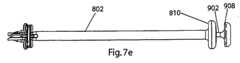
本発明の挿入ハンドルは、頸椎人工椎間板および挿入プレート構築体を治療部位内へ挿入してその中で操作できるように、主として挿入プレートの前方に伸びるステムに係合するために用意されている。挿入ハンドルは、遠位端に長手孔および近位端にフランジを備えるシャフトを有する。挿入ハンドルのシャフトをステムと長手方向に整列させ、その後に挿入ハンドルのシャフトの中空遠位端を挿入プレートに向かって押すと、中空遠位端はステムの外面に摩擦固定される。挿入ハンドルが挿入プレートと係合すれば、挿入ハンドルのシャフトを操作すると頸椎人工椎間板および挿入プレート構築体の操作が達成される。このため外科医は、該構築体を治療領域内へ挿入できる。より特別には、外科医が椎間腔を適正に準備した後、要素の設置面が椎間腔の周辺に適合して要素の椎体接触面の歯が椎骨終板に係合し、そして上方および下方要素のフランジが上方および下方椎骨の前面と各々ぴったりと接触して上方および下方要素が隣接椎骨間に挿入されるように、外科医は頸椎人工椎間板を前方アプローチから椎間腔内へ挿入する。 The insertion handle of the present invention is provided to engage a stem that extends primarily forward of the insertion plate so that the cervical prosthetic disc and insertion plate construct can be inserted into and manipulated within the treatment site. The insertion handle has a shaft with a longitudinal hole at the distal end and a flange at the proximal end. When the shaft of the insertion handle is longitudinally aligned with the stem and then the hollow distal end of the shaft of the insertion handle is pushed toward the insertion plate, the hollow distal end is frictionally secured to the outer surface of the stem. When the insertion handle engages the insertion plate, manipulation of the shaft of the insertion handle accomplishes manipulation of the cervical prosthetic disc and insertion plate construct. This allows the surgeon to insert the construct into the treatment area. More specifically, after the surgeon has properly prepared the intervertebral space, the placement surface of the element fits around the periphery of the intervertebral space and the teeth of the element's vertebral body contacting surface engage the vertebral endplate and The surgeon inserts the cervical prosthesis from the anterior approach into the intervertebral space so that the flanges of the lower and lower elements are in close contact with the front of the upper and lower vertebra, respectively, and the upper and lower elements are inserted between adjacent vertebrae .
該構築体が治療領域内に適正に配置されると、外科医は本発明の挿入プッシャを使用して挿入ハンドルのシャフトを挿入プレートのステムから切り離す。挿入プッシャは、鈍遠位端とフランジを備える近位端とを備える長手シャフトを有する。挿入プッシャのシャフトは、挿入ハンドルのシャフトの長手孔に挿入してその中で平行移動させることができる。挿入プッシャのシャフトは挿入ハンドルのシャフトの長手孔と同じ長さであるので、挿入ハンドルのフランジおよび挿入プッシャのフランジは、シャフトの鈍遠位端が挿入プレートのステムの近位面に接触するまでプッシャのシャフトが長手孔内の端から端まで挿入されるとある間隔だけ隔てられる。したがって、これらのフランジを(例えば、外科医がこれらのフランジを相互に向かって強く押すことによって)結び付けると、挿入ハンドルのシャフトの遠位端と挿入プレートのステムとの間の摩擦固定に打ち勝つであろう。 When the construct is properly positioned within the treatment area, the surgeon uses the insertion pusher of the present invention to disconnect the shaft of the insertion handle from the stem of the insertion plate. The insertion pusher has a longitudinal shaft with a blunt distal end and a proximal end with a flange. The shaft of the insertion pusher can be inserted into the longitudinal bore of the shaft of the insertion handle and translated therein. Since the shaft of the insertion pusher is the same length as the longitudinal hole of the shaft of the insertion handle, the flange of the insertion handle and the flange of the insertion pusher are not in contact until the blunt distal end of the shaft contacts the proximal face of the stem of the insertion plate. When the pusher shaft is inserted end-to-end within the longitudinal bore, it is spaced a distance apart. Thus, when these flanges are tied together (for example, by a surgeon pushing the flanges strongly toward each other), they overcome the frictional fixation between the distal end of the shaft of the insertion handle and the stem of the insertion plate. Let's go.
挿入ハンドルが抜去されると、外科医は本発明のドリルガイドを使用して外科医による上方および下方要素のフランジの骨ネジ穴に通して椎骨内への骨ネジのドリリングを誘導する。ドリルガイドは、ドリルガイドをステム上に配置してステムと整列させることができるようにステムに適応する中心孔を備えて構成された遠位端を備える長手シャフトを有する。遠位端は、さらに相互に対して好ましい骨ネジドリリング経路で各長手軸を有する2つのガイド孔を有するように構成される。中心孔が挿入プレートのステム上に配置されると、ドリルガイドのシャフトはステム上で、その中でガイド孔が一方のフランジにある骨ネジ穴と、または他方のフランジ上の骨ネジ穴と整列している2つの好ましい位置のいずれかに回転させることができる。 When the insertion handle is removed, the surgeon uses the drill guide of the present invention to guide the drilling of the bone screw into the vertebra by the surgeon through the bone screw holes in the flanges of the upper and lower elements. The drill guide has a longitudinal shaft with a distal end configured with a central hole adapted to the stem so that the drill guide can be positioned on and aligned with the stem. The distal end is further configured to have two guide holes with each longitudinal axis in a preferred bone screw drilling path relative to each other. When the center hole is located on the stem of the insertion plate, the drill guide shaft is on the stem, where the guide hole aligns with the bone screw hole on one flange or the bone screw hole on the other flange Can be rotated to one of two preferred positions.
上方椎体へ上方要素のフランジを固定するために、外科医は挿入プレートのステム上へドリルガイドのシャフトを配置し、そしてドリルガイドを第1の好ましい位置内に回転させる。適切な骨ドリルおよび共働するドリルビットを使用して、外科医は上方骨ネジのための上方タップ穴をドリリングする。外科医は次に、ガイド孔が上方骨ネジ穴をもはや被覆しなくなるまで挿入プレートのステム上のドリルガイドのシャフトを回転させる。外科医は、次に適切な外科用骨ネジスクリュードライバを用いて上方タップ穴の中に上方骨ネジをネジ入れることができる。次に下方要素のフランジを下方椎体へ固定するために、外科医はドリルガイドが第2の好ましい位置になるまで、挿入プレートのステム上のドリルガイドのシャフトをさらに回転させ、そして下方骨ネジタップ穴をドリリングして下方骨ネジを同一方法でそれらの中にネジ入れる。 To secure the upper element flange to the upper vertebral body, the surgeon places the shaft of the drill guide over the stem of the insertion plate and rotates the drill guide into a first preferred position. Using an appropriate bone drill and cooperating drill bit, the surgeon drills the upper tap hole for the upper bone screw. The surgeon then rotates the shaft of the drill guide on the stem of the insertion plate until the guide hole no longer covers the upper bone screw hole. The surgeon can then screw the upper bone screw into the upper tap hole using a suitable surgical bone screw screwdriver. Next, to secure the flange of the lower element to the lower vertebral body, the surgeon further rotates the shaft of the drill guide on the stem of the insertion plate until the drill guide is in the second preferred position, and the lower bone screw tapped hole Drill down and screw the lower bone screws into them in the same way.
上方および下方要素が隣接椎骨へ固定されると、外科医は挿入プレートのステムから、そして治療領域からドリルガイドを抜去する。適切な外科用スクリュードライバを用いて、外科医は次に挿入プレートを該要素のフランジに接触させて保持する取り付けネジを抜去し、治療領域から挿入プレートおよび取り付けネジを抜去する。 When the upper and lower elements are secured to the adjacent vertebrae, the surgeon removes the drill guide from the stem of the insertion plate and from the treatment area. Using a suitable surgical screwdriver, the surgeon then removes the mounting screw that holds the insertion plate in contact with the flange of the element and removes the insertion plate and mounting screw from the treatment area.
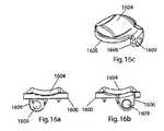
取り付けネジおよび挿入プレートが抜去されると、外科医は本発明のクリップアプリケータを使用して骨ネジを保持することに役立つようにフランジに保持クリップを取り付ける。クリップの各々は中央取り付け孔、およびそれから伸びている、1対の反対方向に側方に伸びるフランジおよび上向き(または下向き)に伸びるフック状フランジを有する。クリップは、要素のフランジに(1つのクリップを各フランジへ)ぱちんとはめることができる。クリップの側方に伸びるフランジの各々は、骨ネジが抜けるのをこれらのクリップが防止するのに役立つように、この方法でクリップがフランジに取り付けられると骨ネジの頭部の各1つの少なくとも一部分を被覆するサイズにされている。また別の実施形態では、保持デバイスはネジ切り部材および頭部フランジ部材を含み、ネジ切り部材は取り付けネジおよび挿入プレートが抜去されることによって残される取り付けネジ穴のネジ切り開口部内に受け入れられる。 Once the mounting screw and insertion plate are removed, the surgeon attaches the retaining clip to the flange to help retain the bone screw using the clip applicator of the present invention. Each of the clips has a central mounting hole and a pair of oppositely extending laterally extending flanges and an upward (or downward) hook-like flange extending therefrom. The clips can be snapped onto the element flanges (one clip to each flange). Each of the flanges extending to the sides of the clip is at least a portion of each one of the heads of the bone screw when the clip is attached to the flange in this manner to help prevent the clips from being pulled out of the bone screw. The size is covered. In yet another embodiment, the retaining device includes a threaded member and a head flange member, the threaded member being received within a threaded opening in the mounting screw hole left by removal of the mounting screw and the insertion plate.
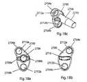
さらにまた、例えば2つの隣接頸椎椎間腔内に植え込むために適合するまた別の複式頸椎人工椎間板が開示される。この構成は、また別の上方頸椎椎間腔内に植え込むための上方頸椎人工椎間板(上方要素およびまた別の下方要素を含む)を含み、さらにまた隣接する下方頸椎椎間腔内へ植え込むためのまた別の下方頸椎人工椎間板(また別の上方要素および下方要素を含む)を含む。例示したまた別の上方実施形態は図1a〜3fの頸椎人工椎間板と構造が同一であるが、ただし下方要素のフランジは相違する構成であり、骨ネジ穴を備えていないことを除く。例示したまた別の下方実施形態は図1a〜3fの頸椎人工椎間板と構造が同一であるが、ただし上方要素のフランジは相違する構成であり、骨ネジ穴を備えていないことを除く。 Yet another alternative cervical prosthetic disc is disclosed that is adapted for implantation within, for example, two adjacent cervical disc space. This configuration includes an upper cervical prosthetic disc (including an upper element and another lower element) for implantation in another upper cervical disc space, and also for implantation into an adjacent lower cervical disc space It also includes another lower cervical prosthetic disc (including another upper and lower element). The illustrated further upper embodiment is identical in construction to the cervical prosthetic disc of FIGS. 1a-3f, except that the flange of the lower element is of a different configuration and does not include a bone screw hole. Another illustrated lower embodiment is identical in construction to the cervical prosthetic disc of FIGS. 1a-3f, except that the flange of the upper element has a different configuration and does not include a bone screw hole.
より特別には、このまた別の構成のまた別の上方頸椎人工椎間板では、また別の下方要素のフランジは骨ネジ穴を有していないが、また別の下方要素をまた別の上方挿入プレートへ取り付けるための取り付けネジ穴を有する。同様に、このまた別の構成のまた別の下方頸椎人工椎間板では、また別の上方要素のフランジは骨ネジ穴を有していないが、また別の上方要素をまた別の下方挿入プレートへ取り付けるための取り付けネジ穴を有する。また別の下方要素のフランジの広がりは中線から右(正面図において)へ側方に偏っており、そしてまた別の上方要素のフランジの広がりは中線から左(正面図において)へ側方に偏っているので、これらのフランジは、また別の上方頸椎人工椎間板のまた別の下方要素およびまた別の下方頸椎人工椎間板のまた別の上方要素がこのまた別の構成で植え込まれると相互に近寄らない。 More particularly, in this further configuration of another upper cervical prosthetic disc, the flange of the further lower element does not have a bone screw hole, but another lower element may be replaced with another upper insertion plate. There is a mounting screw hole for mounting to. Similarly, in this alternative configuration of another lower cervical prosthetic disc, the flange of another upper element does not have a bone screw hole, but another upper element is attached to another lower insertion plate. There is a mounting screw hole. Another lower element flange spreads laterally from the midline to the right (in the front view), and another upper element flange spreads laterally from the midline to the left (in the front view). These flanges are interrelated when another lower element of another upper cervical prosthetic disc and another upper element of another lower cervical artificial disc are implanted in this other configuration. Keep away from.
また別の上方挿入プレートは上記に記載した挿入プレートと構造において同一であるが、ただし下方フランジが、その取り付けネジ穴をまた別の下方要素の偏った取り付けネジ穴と整列させるために中線から(正面図において右へ)偏っていることを除く。同様に、また別の下方挿入プレートは上記に記載した挿入プレートと構造において同一であるが、ただし上方フランジが、その取り付けネジ穴をまた別の上方要素の偏った取り付けネジ穴と整列させるために中線から(正面図において左へ)偏っていることを除く。
したがって、また別の上方挿入プレートによって保持されているまた別の上方頸椎人工椎間板の上方および下方要素、ならびにまた別の下方挿入プレートによって保持されているまた別の下方頸椎人工椎間板の上方および下方要素は、挿入ハンドル、挿入プッシャ、ドリルガイド、クリップ(一番上の要素および一番下の要素だけが骨ネジによって固定されるので、1つは一番上の要素のフランジに、そして1つは一番下の要素のフランジに)、およびクリップアプリケータを使用して、頸椎人工椎間板の植え込みに関して上述した方法で植え込むことができる。The other upper insert plate is identical in construction to the insert plate described above, except that the lower flange is from the midline to align its mounting screw hole with the offset mounting screw hole of another lower element. Excludes being biased (to the right in the front view). Similarly, another lower insert plate is identical in construction to the insert plate described above, except that the upper flange aligns its mounting screw holes with the offset mounting screw holes of another upper element. Except for being biased from the middle line (to the left in the front view).
Thus, the upper and lower elements of another upper cervical prosthetic disc held by another upper insertion plate and the upper and lower elements of another lower cervical prosthetic disc held by another lower insertion plate Insert handle, insert pusher, drill guide, clip (only the top and bottom elements are fixed by bone screws, so one is on the flange of the top element and one is (On the flange of the bottom element), and using a clip applicator, can be implanted in the manner described above with respect to implantation of the cervical artificial disc.
以下では添付の図面を参照しながら本発明についてより特別に説明するが、当業者であれば本発明の機能および結果を達成しながら本明細書に記載した本発明を修飾できることが最初に理解されなければならない。したがって、以下の説明は本発明の広い範囲内の特別な構造、態様および特徴の例示および典型であってそのような広い範囲を限定するものではないと理解すべきである。同様の番号は本明細書の全体を通して同様の要素の類似機能に関連する。 While the present invention will be described more particularly hereinafter with reference to the accompanying drawings, it is first understood that one skilled in the art can modify the invention described herein while achieving the function and results of the invention. There must be. Accordingly, it is to be understood that the following description is exemplary and exemplary of specific structures, aspects and features within the broad scope of the present invention and is not intended to limit such broad scope. Like numbers relate to like functions of like elements throughout the specification.
以下では、本発明の器具類と一緒に使用するための、本発明の頸椎人工椎間板の好ましい実施形態について記載する。 The following describes a preferred embodiment of the cervical prosthetic disc of the present invention for use with the devices of the present invention.
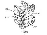
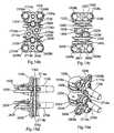
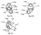
図1a〜3fを参照すると、頸椎人工椎間板400の上方要素500が正面図(図1a)、側面図(図1b)、および底面図(図1c)で示されている;頸椎人工椎間板400の下方要素600が正面図(図2a)、側面図(図2b)、および平面図(図2c)で示されている;ならびに上方および下方要素500、600の組立体400が平面図(図3a)、側面図(図3b)、正面図(図3c)、背面図(図3d)、前外側斜視図(図3e)、および後外側斜視図(図3f)で示されている。 With reference to FIGS. 1 a-3 f, the
頸椎人工椎間板400は、‘702号出願の頸椎人工椎間板のまた別の実施形態である。例示した頸椎人工椎間板のまた別の実施形態は、構造においては‘702号出願に記載の頸椎人工椎間板100と同一であるが(したがって、同様の構成要素は同様に、しかし100番台ではなく400番台で、200番台ではなく500番台で、そして300番台ではなく600番台でナンバリングされている)、ただし椎骨取り付けフランジは、それらが本明細書に記載した器具類によって係合されるのに適合するように相違する構成にされていることを除く。(‘702号出願は2つの骨ネジ穴508a、508bを備える上方要素のフランジ506、および1つの骨ネジ穴608を備える下方要素のフランジ606を有する頸椎人工椎間板100について例示かつ記載しているが、‘702号出願は、穴の数およびフランジの構成は‘702号出願に記載されたように発明の範囲から逸脱せずに修飾できると説明していることに留意されたい)。 The
より特別には、このまた別の実施形態では、頸椎人工椎間板400の上方要素500は好ましくは上方要素500の前縁から上向きに伸びている椎体取り付け構造(例、フランジ)506を有し、そして好ましくはそれに接触して固定されるべき上方椎体の前方周辺の湾曲に近似する外側湾曲を有する。取り付けフランジ506には、好ましくは本発明のクリップ1150a(以下で説明する)に適応する、中線上に中心がある平坦な凹所507が用意されている。取り付けフランジ506には、好ましくは中線の両側に対称性に配置された少なくとも1つ(例えば、2つ)の骨ネジ穴508a、508bがさらに用意されている。好ましくは、これらの穴508a、508bは、好ましい骨ネジの駆動線に沿って方向付けられた長手軸を有する。例えば、このまた別の実施形態では、好ましい骨ネジ駆動線は、骨ネジの斜め打ち込みを促進するために、上向きに5度で、そして内向き(相互に向かって)7度(計14度の収束)で屈曲している(以下で説明され、図12a〜hに示されている)。これらの骨ネジ穴508a、508bの中間には、植え込むための挿入プレート700(以下で説明する)へ上方要素500を取り付けるために少なくとも1つの取り付け機構(例、取り付けネジ穴)509が用意されている。 More specifically, in this alternative embodiment, the
同様に、このまた別の実施形態では、頸椎人工椎間板400の下方要素600もまた好ましくは下方要素600の前縁から下向きに伸びている椎体取り付け構造(例、反対方向に方向付けられて同様に構成された椎体取り付けフランジ)606を有し、そして好ましくはそれに接触して固定されるべき下方椎体の前方周辺の湾曲に近似する外側湾曲を有する。取り付けフランジ606には、好ましくは本発明のクリップ1150b(以下で説明する)に適応する、中線上に中心がある平坦な凹所607が用意されている。取り付けフランジ606には、好ましくは中線の両側に対称性に配置された少なくとも1つ(例えば、2つ)の骨ネジ穴608a、608bがさらに用意されている。好ましくは、これらの穴608a、608bは、好ましい骨ネジの駆動線に沿って方向付けられた長手軸を有する。例えば、このまた別の実施形態では、好ましい骨ネジ駆動線は、骨ネジの斜め打ち込みを促進するために、下向きに5度で、そして内向き(相互に向かって)7度(計14度の収束)で屈曲している(以下で説明し、図12a〜hに示した)。これらの骨ネジ穴608a、608bの中間には、植え込むための挿入プレート700(以下で説明する)へ下方要素600を取り付けるために少なくとも1つの取り付け機構(例、取り付けネジ穴)609が用意されている。 Similarly, in this alternative embodiment, the
頸椎人工椎間板を植え込む前に、外科医は椎間腔を準備するであろう。典型的には、これには治療部位へのアクセスを確立するステップと、損傷した自然椎間板を除去するステップと、椎間腔に隣接する椎骨の終板表面を準備するステップと、そして椎間腔を伸延させるステップと、が含まれるであろう(本発明の頸椎人工椎間板、および本明細書に記載した器具類および植え込み方法は、終板の準備が必要でも最小限しか必要としないことに留意されたい)。より特別には、治療部位へのアクセスを確立した後に、外科医は、好ましくはできる限り線維輪を無傷で残しながら自然椎間板物質を除去するであろう。次に、外科医は頸椎椎間腔の口部に突出している前方骨棘、ならびに頸椎人工椎間板の配置または関節の運動を妨害する可能性があるいずれかの側方骨棘を除去するであろう。バーツールを用いて、外科医は次に、湾曲から逸脱する何らかの表面異常を取り除くことによって、確実に椎体の前面の自然外側湾曲が一様であることを保証する。同様にバーツールを用いて、外科医は、湾曲または平坦さから逸脱する何らかの表面異常を除去することによって、上方椎体の終板表面の自然湾曲および下方椎体の終板表面の自然な平坦さが一様であることを保証するであろう。その後、外科医は頸椎人工椎間板を受け入れるための適切な高さへ椎間腔を伸延させるであろう。例えばCaspar伸延器(Distractor)などの当分野において知られている任意の伸延用ツールもしくは方法を使用すると、椎間腔を伸延させることができる、および/または開いて保持することができる。追加して、あるいはまた、本発明の頸椎人工椎間板トライアルを使用すると椎間腔を伸延させることができる(以下で説明する)。 Prior to implanting the cervical artificial disc, the surgeon will prepare the intervertebral space. Typically, this includes establishing access to the treatment site, removing the damaged natural disc, preparing the endplate surface of the vertebra adjacent to the disc space, and the disc space (Note that the cervical prosthetic disc of the present invention, and the instruments and implantation methods described herein require minimal, even if end plate preparation is required. I want to be) More specifically, after establishing access to the treatment site, the surgeon will remove the natural disc material, preferably leaving the annulus as intact as possible. The surgeon will then remove the anterior osteophyte protruding into the mouth of the cervical disc space as well as any lateral osteophyte that may interfere with cervical prosthetic disc placement or joint movement . Using the bar tool, the surgeon then ensures that the natural lateral curvature of the anterior surface of the vertebral body is uniform by removing any surface abnormalities that deviate from the curvature. Similarly, using the bar tool, the surgeon can remove the natural curvature of the endplate surface of the upper vertebral body and the natural flatness of the endplate surface of the lower vertebral body by removing any surface abnormalities that deviate from the curvature or flatness. Will be guaranteed to be uniform. The surgeon will then distract the intervertebral space to an appropriate height for receiving the cervical prosthetic disc. Any distraction tool or method known in the art, such as, for example, a Caspar distractor, can be used to distract and / or hold open the intervertebral space. In addition or alternatively, the cervical prosthetic disc trial of the present invention can be used to distract the intervertebral space (described below).
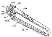
ここで図4a〜fを参照すると、本発明の頸椎人工椎間板トライアル1200が平面図(図4a)、側面図(図4b)、側面図(頭部のみ)(図4c)、背面図(図4d)、正面図(図4e)、前外側斜視図(頭部のみ)(図4f)、および後外側斜視図(頭部のみ)(図4g)で示されている。 Referring now to FIGS. 4a-f, a cervical
好ましくは、主として伸延させた椎間腔内に植え込まれる頸椎人工椎間板(例、図1a
〜3fの頸椎人工椎間板400)の適切なサイズ(または特定サイズの頸椎人工椎間板を植え込むことができるかどうか)を決定するために複数の頸椎人工椎間板トライアルが提供される。植え込まれるべき各頸椎人工椎間板に対して、複数のサイズの頸椎人工椎間板を利用できるのが好ましいであろう。すなわち、複数の同一タイプの頸椎人工椎間板を利用でき、複数の各々はそれが対応する寸法の椎間腔内に適合することを可能にする各設置面および深さの寸法の組み合わせを有するのが好ましい。例えば、複数の頸椎人工椎間板は、計27個のデバイスについて12mm×14mm、14mm×16mm、または16mm×18mmである楕円形設置面、および1mm増分で6mmから14mmの範囲内の深さを有する頸椎人工椎間板を含むことができよう。したがって、特定の複数のサイズの様々な頸椎人工椎間板と一緒に使用するための複数のトライアルの各々は複数のサイズの様々な頸椎人工椎間板の各1つの設置面および深さ寸法セットに対応する各設置面および深さ寸法セットを有するのが好ましいであろう。例えば、本明細書に記載した頸椎人工椎間板のセットと一緒に使用するための複数のトライアルは、計27個の静的トライアルについて12mm×14mm、14mm×16mm、もしくは16mm×18mmである楕円形設置面、および1mm増分で6mmから14mmの範囲内の深さを有するトライアルを含むことができよう。頸椎人工椎間板および/またはトライアルは本発明の範囲から逸脱することなく様々な寸法で提供できること、そして本明細書に詳細に同定および定量した寸法は単なる例であることを理解されたい。さらに、トライアルのセットには頸椎人工椎間板のセット内の各頸椎人工椎間板と同一数のトライアルを含む必要はなく、むしろそのセット内のいずれか特定の頸椎人工椎間板に対してトライアルセット内には1つ、もしくは2つ以上のトライアルが含まれてよい、または1つも含まれていなくてもよいことを理解されたい。Preferably, a cervical prosthetic disc (eg, FIG.
A plurality of cervical prosthetic disc trials are provided to determine the appropriate size of ˜3f cervical prosthetic disc 400 (or whether a specific size cervical prosthetic disc can be implanted). It would be preferable to be able to utilize multiple sizes of cervical prosthetic discs for each cervical prosthetic disc to be implanted. That is, a plurality of the same type of cervical prosthetic disc can be utilized, each having a combination of each mounting surface and depth dimension that allows it to fit within a correspondingly sized disc space. preferable. For example, a plurality of cervical vertebral prosthetic discs may have a cervical vertebra having an elliptical mounting surface that is 12 mm × 14 mm, 14 mm × 16 mm, or 16 mm × 18 mm for a total of 27 devices, and a depth in the range of 6 mm to 14 mm in 1 mm increments An artificial disc could be included. Thus, each of the plurality of trials for use with various cervical vertebral prosthetic discs of a particular multitude of sizes corresponds to each one mounting surface and depth dimension set of various cervical vertebral prosthetic discs of multiple sizes. It would be preferable to have an installation surface and a depth dimension set. For example, multiple trials for use with the set of cervical prosthetic discs described herein are oval installations that are 12 mm x 14 mm, 14 mm x 16 mm, or 16 mm x 18 mm for a total of 27 static trials Could include a trial with a surface and a depth in the range of 6 mm to 14 mm in 1 mm increments. It should be understood that cervical prosthetic discs and / or trials can be provided in a variety of dimensions without departing from the scope of the present invention, and the dimensions identified and quantified in detail herein are merely examples. In addition, the trial set need not include the same number of trials as each cervical prosthetic disc in the set of cervical prosthetic discs, but rather one in the trial set for any particular cervical prosthetic disc in the set. It should be understood that one, two or more trials may be included, or none may be included.
頸椎人工椎間板トライアル(図4a〜gに示した頸椎人工椎間板トライアル1200は複数のトライアルに含まれる全トライアルの例である;好ましくは、複数のトライアル内のトライアルは上記に記載した特定寸法に関してのみ相互から相違する)の各々は、構成された遠位端1204とハンドル1206を有する近位端とを有するシャフト1202を含む。好ましくは、近位端には、例えばトライアル1200の重量を減少させるため、トライアル1200の操作を促進するため、そして器具用トレイ突出部によって係合されるための機能を提供するために、操作機能(例、穴1216)が用意されている。遠位端は、頸椎人工椎間板の関連寸法に近似するように構成されている。例示した実施形態(例)においてより特別には、遠位端1204はトライアル構成(例えば、頭部1208は12mm×14mmの寸法にされた楕円形設置面、および6mmの厚さ)を有する。頭部1208の上面1210は、頸椎人工椎間板400の上方要素500の椎体接触面の構成に類似して凸状である(しかし歯を備えていない)。頭部1208の下面1212は、頸椎人工椎間板400の下方要素600の椎体接触面の構成に類似して平坦である(しかし歯を備えていない)。このため、これらの寸法を備える例示した実施形態は、同一の高さおよび設置面の寸法を有する頸椎人工椎間板のサイズに近似している。歯を有していない頸椎人工椎間板トライアルは、終板表面を傷つけることなく椎間腔に挿入したり抜去したりすることができる。頸椎人工椎間板トライアル1200はさらにまた、トライアル1200が椎間腔内の奥深くに挿入される前に上方椎体の前面に係合するために、好ましくは頭部1208の前縁に配置された過挿入防止機能(例、椎体ストッパ1214)を有する。トライアル1200の本体は、好ましくは例えば頭部1208がこの方法でシャフト1202を移動させることによって椎間腔内へ推進されなければならない場合は、例えば上向きおよび下向き運動のためにシャフト1202へ安定性を提供する1つ以上の構造支持機構(例、頭部1208からシャフト1202の下方へ前方へ伸びるリブ1216)を有する。さらに、好ましくは図示したように、頭部1208には、例えば椎骨終板が離れるように推進する楔として機能することによって、頭部1208の椎間腔内への挿入を促進するための挿入促進機能(例、後方へ向かって減少するテーパ)を備えている。好ましくは、図示したように、上面1210はおよそ5度で十分にテーパ付けされており、そして下面1212の遠位半分はおよそ4度でテーパ付けされている。 Cervical prosthetic disc trial (the cervical
したがって、外科医は少なくとも1つ(または必要に応じて2つ以上)のトライアルを準備された椎間腔に挿入したり抜去したりすることができる。上述したように、トライアルは準備された椎間腔を伸延させるために有用である。例えば、椎骨間に打ち込める最も大きな伸延器から始めて、外科医はトライアルの頭部1208を挿入し(トライアルの頭部1208のテーパ付けは椎骨終板が離れるように推進するための楔として機能することによってこの挿入を促進する)、次にトライアルのハンドル1206を上下させて線維輪および取り囲んでいる靱帯を緩めて骨をさらに遠くへ離れさせる。線維輪および靱帯が緩められると、外科医はトライアルの頭部1208を椎間腔から抜去し、それを(高さに関して)次に最も大きなトライアルの頭部1208に取り換える。外科医は次にトライアルのハンドル1206を上げ下げしてさらに線維輪および靱帯を緩める。外科医は次にトライアルの頭部1208を抜去して(高さに関して)次に最も大きなトライアルの頭部1208と取り換え、椎間腔が適切な高さに伸延させられるまでますます大きいトライアルを用いてこの方法を続ける。この段階的伸延法は、頸椎人工椎間板が植え込まれる前に、伸延させた椎間腔が沈降を最小限に抑えながら伸延させた高さのままで維持されることを引き起こす。適切な高さは、線維輪および靱帯を保護しながら椎間腔の高さを最大化する高さである。 Thus, the surgeon can insert or remove at least one (or more than one if necessary) trial into the prepared intervertebral space. As described above, the trial is useful for distracting the prepared intervertebral space. For example, starting with the largest distractor that can be driven between the vertebrae, the surgeon inserts the trial head 1208 (the taper of the
使用される伸延方法とは無関係に、トライアルの頭部は各々利用できる頸椎人工椎間板の関連寸法に近似しているので、頸椎人工椎間板トライアルは準備された椎間腔にとって最も適切な頸椎人工椎間板のサイズを見つけるために有用である。椎間腔が伸延させられると、外科医は1つ以上のトライアルの頭部を挿入したり抜去したりして、使用するために適切なサイズの頸椎人工椎間板を決定することができる。適切なサイズが決定されると、外科医は選択した頸椎人工椎間板の植え込みに取りかかる。 Regardless of the distraction method used, the cervical prosthetic disc trial is the most appropriate cervical prosthetic disc for the prepared disc space, as each trial head approximates the relevant dimensions of the available cervical prosthetic disc. Useful for finding the size. Once the intervertebral space is distracted, the surgeon can insert or remove the head of one or more trials to determine an appropriately sized cervical prosthetic disc for use. Once the proper size is determined, the surgeon will proceed to implant the selected cervical prosthetic disc.
以下では、頸椎人工椎間板を植え込む際に使用するための好ましい方法および器具類について説明する。
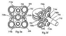
今度は図5a〜fを参照すると、本発明の挿入器具類の挿入プレート700が平面図(図5a)、側面図(図5b)、正面図(図5c)、および背面図(図5d)で示されている。図5eおよび5fは、頸椎人工椎間板400に取り付けられた挿入プレート700の正面図(図5e)および前外側斜視図(図5f)を示している。In the following, preferred methods and instruments for use in implanting a cervical artificial disc will be described.
Referring now to FIGS. 5a-f, the
挿入プレート700は、第1取り付け領域704a(好ましくは上向きに伸びるフランジ)および第2取り付け領域704b(好ましくは下向きに伸びるフランジ)を備えるベース702、ならびに一次取り付け機構(例、前方に伸びる中央ステム)706を有する。ステム706からベース702への接続は、好ましくは例えば2つの反対方向および側方に伸びるキーフランジ708a、708bのような軸回転防止機能を含む。ステム706は、好ましくはベース702から離れるにつれて減少する直径を有するようにテーパ付けされている近位部分710を有する。すなわち、テーパ付け近位部分710は最初は小さな直径を有するが、この直径はベース702に向かって徐々に最終のより大きな直径へ増加する。ベース702は、好ましくは平坦な上面および湾曲した下面を有する後方へ伸びる突起部716を有する。 The
本発明の挿入プレート700は、上方および下方要素500、600の好ましい同時植え込みを促進するために頸椎人工椎間板400に取り付けられる。上方および下方要素500、600は、植え込みのために適切な相互に対して好ましい関係で挿入プレート700によって保持される。より特別には、図3a〜f、5eおよび5fに示したように、要素500、600は好ましくは相互に、要素の周囲と、および相互に軸方向へ整列したフランジ506、606と軸回転可能に整列しており、そしてベアリング面512、612と接触させて保持されている。突起部716は、この好ましい関係を確立かつ維持するのに役立つように、突起部716の平坦な上面を上方要素500の内向面の平坦な前方部分と接触させ、そして突起部716の湾曲した下面を下方要素600の内向面の湾曲した前方部分と接触させて、要素500、600の内向面の前方位置間の分離を維持する。 The
要素500、600を挿入プレート700へ取り付けるためにはあらゆる適切な方法または機構を使用できるが、好ましい配列について説明する。すなわち、図示したように、そして上述したように要素500、600のフランジ506、606各々が(上述した骨ネジ穴508a、508b、608a、608bを有するのに加えて)少なくとも1つの取り付け機構(例、取り付けネジ穴509、609)を有し、そしてそれらの要素500、600が植え込みのために好ましい関係で配置されると頸椎人工椎間板400の要素500、600のフランジ506、606上の取り付けネジ穴509、609の間隔に適合する(および各々が各1つと同一直線上にある。)ように間隔をあけて挿入プレート700が2つ(各1つが各取り付けネジ穴509、609と整列可能である、少なくとも2つ)の対応する取り付け機構(例、取り付けネジ穴712a、712b)を有するのが好ましい。したがって、取り付けネジ714a、714bまたはその他の適切な固定器具類は、要素500、600が挿入プレート700に対して、および相互に対して不動であるように、同一直線上の取り付けネジ穴対509、712aおよび609、712b(1本のネジを各対に通して)を通して固定される。そこで、この構成では、上方要素500、下方要素600、および挿入プレート700構築体は単一ユニットとして操作することができる。 Although any suitable method or mechanism can be used to attach the
好ましくは、各サイズの頸椎人工椎間板については、外科医へ納品される前に上述した構成が確立される(そして当分野において知られている方法によりブリスターパック内で滅菌される)。すなわち、以下で説明するように、外科医は頸椎人工椎間板を植え込むためにブリスターパックを単純に開封し、そして該構築体へ追加の植え込み用ツールを適用しさえすればよい。好ましくは、挿入プレートの構成もしくは寸法は、様々な高さの頸椎人工椎間板に適応するために(複数の相違する挿入プレートを提供することによって、または単一の動的に修正可能な挿入プレートを提供することによって)修正することができる。例えば、フランジ704a、704b上の取り付けネジ穴712a、712bの位置は調整でき(例えば、より高い高さの人工椎間板のためにはいっそう遠くへ離れさせ、より低い高さの人工椎間板のためにはいっそう近付ける)、そしてフランジ704a、70bのサイズは新規の穴の位置に対して構造的安定性を提供するように調整できる。好ましくは、そのほかの点では、製造が容易になり、製造費用をより低く抑えるために、挿入プレートの構成および寸法を修正する必要はない。 Preferably, for each size cervical prosthetic disc, the configuration described above is established (and sterilized in a blister pack by methods known in the art) prior to delivery to the surgeon. That is, as will be described below, the surgeon simply opens the blister pack to implant the cervical prosthetic disc and applies an additional implantation tool to the construct. Preferably, the configuration or dimensions of the insertion plate are adapted to accommodate different heights of the cervical prosthetic disc (by providing multiple different insertion plates or a single dynamically modifiable insertion plate (By providing) can be corrected. For example, the position of the mounting
上述した構築体の構成は外科医によく知られている方法で頸椎人工椎間板を提示することに留意されたい。すなわち、説明として、現代の頸椎癒合手術は頸椎椎骨間に癒合器具(例、骨性もしくは多孔性ケージ)を配置するステップ、および骨の前面へ頸椎癒合プレートを取り付けるステップを含む。広範に使用されている頸椎癒合デバイス(1つの例の単一高さの癒合プレート1300は図13aに正面図で、そして図13bに側面図で示されている)は、プレート1300の上端1304上の1対の側方へ間隔をあけた骨ネジ穴1302a、1302b、およびプレート1300の下端1308上の1対の側方に間隔をあけた骨ネジ穴1306a、1306bを備えて構成されている。プレート1300を骨に取り付けるために、2本の骨ネジが上端の骨ネジ穴1302a、1302bを通して上方の骨内に配置され、そして2本の骨ネジが下端の骨ネジ穴1306a、1306bを通して下方の骨内に配置される。これは骨が相互に対して移動するのを防止し、そして骨が癒合器具を用いて相互に癒合するのを可能にする。 Note that the construction of the construct described above presents the cervical prosthetic disc in a manner well known to surgeons. That is, by way of illustration, modern cervical fusion surgery includes placing a fusion device (eg, a bony or porous cage) between the cervical vertebrae and attaching a cervical fusion plate to the anterior surface of the bone. A widely used cervical fusion device (one example single-
したがって、図5eから明らかなように、頸椎人工椎間板400の上方および下方要素500、600が好ましい空間関係で保持されると、要素500、600のフランジ506、606、およびそれらの骨ネジ穴508a、508bは外科医によく知られた頸椎癒合プレートの構成に類似する頸椎ハードウエアおよび骨ネジ穴構成を提供する。挿入プレート700への要素500、600の取り付けは、頸椎癒合プレートが骨へ取り付けるための単一ユニットとして操作可能である方法に類似して、要素500、600を(挿入プレート700を操作することによって)植え込むための単一ユニットとして操作することを可能にする。本発明のこの態様は、頸椎人工椎間板の植え込み手技を単純化かつ簡素化する。 Thus, as is apparent from FIG. 5e, when the upper and
上述したように、頸椎人工椎間板400および挿入プレート700構築体は、好ましくはインプラントトレイに入れて無菌(例、ブリスターパック内)で提供される(トレイには、好ましくは各サイズの頸椎人工椎間板のための構築体が充填される)。この構築体は、好ましくは挿入ハンドル800(以下で説明する)の準備のできた受け入れのために挿入プレート700のステム706を上向きにしてインプラントトレイ内に据えられる。 As described above, the
今度は図6a〜図6eを参照すると、本発明の挿入器具類の挿入ハンドル800が平面図(図6a)、側面図(図6b)、正面図(図6c)、および後外側図(遠位端のみ)(図6d)で示されている。図6eは、挿入プレート700のステム706に取り付けられた挿入ハンドル800の前外側斜視図である。図6fは、図6eの遠位端の拡大図である。 Referring now to FIGS. 6a-6e, the insertion handle 800 of the insertion instrument of the present invention is shown in plan, FIG. End only) (shown in FIG. 6d). FIG. 6 e is a front-outside perspective view of the insertion handle 800 attached to the
挿入ハンドル800は、頸椎人工椎間板400および挿入プレート700構築体を治療部位内へ挿入してその中で操作できるように、主として挿入プレート700のステム706に係合するために用意されている。挿入ハンドル800は遠位端806で取り付け機構(例、長手孔)804および近位端808で操作機構(例、フランジ)810を備えるシャフト802を有する。好ましくは、長手孔804は、遠位端806の内径が遠位端806の近位部分での最初のより大きな内径から遠位端806の遠位縁での最終のより小さい内径まで、遠位端806へ向かって減少するように、遠位端806で内側テーパを有する。遠位端806はさらにまた好ましくは、遠位端806から近位方向へ伸びる例えば2つ(少なくとも1つ)のキースロット814a、814bなどの軸回転防止機能を有する。各スロット814a、814bは、遠位端806がステム706と係合されるとベース702からステム706への結合部でキーフランジ708a、708bに適応するように成形されている。挿入ハンドル800がそれから形成される物質(好ましくは、例えばUltem(商標))、およびさらにキースロット814a、814bの存在は、挿入プレート700のテーパ付きステム706に係合するための必要に応じて中空遠位端806の直径が拡大することを許容する。より特別には、挿入ハンドル800の中空遠位端806の静止時直径(拡張する前)は、挿入プレート700のステム706のテーパ付き近位部分710の最初の直径より漸増的に大きく、そして挿入プレート700のステム706のテーパ付き近位部分710の最終直径より小さい。したがって、挿入ハンドルのシャフト802をステム706と長手方向に整列させ、その後に挿入ハンドルのシャフト802の中空遠位端806を挿入プレート700に向かって押すと、中空遠位端806がステム706のテーパ付き近位部分710を最初は容易に包含することを引き起こす(テーパ付き近位部分710の最初の直径は中空テーパ付き遠位端806の静止時直径より小さいからである)。挿入ハンドルのシャフト802が挿入プレートのベース702に向かって移動し続けると、中空遠位端806はテーパ付き近位部分710の直径が増加することによって対応される。したがって、中空遠位端806の直径は(スロットが狭くなるにつれてシャフト802本体物質およびキースロット814a、814bが許容することによって)増加する直径を受け入れるための対応下で拡大する。最後には、外力下で移動し続けると、中空遠位端806の内面はテーパ付き近位部分710の外面に摩擦固定される。キースロット814a、814bの各々は、ベース702からステム706への結合部でキーフランジ708a、708bの各1つにまたがっている。これは、挿入ハンドル800が挿入プレート700に対して挿入ハンドルのシャフト802の(挿入ハンドルのシャフト802の長手軸の周囲での)回転を防止する能力を増強する。挿入ハンドル800によるステム706への係合を確立する他の方法または機構は本発明の範囲から逸脱せずに使用できることを理解されたい。 The insertion handle 800 is provided primarily to engage the
挿入ハンドル800が挿入プレート700と係合すれば、挿入ハンドルのシャフト802を操作すると頸椎人工椎間板400および挿入プレート700構築体の操作を実施できる。このため、外科医はインプラントトレイから構築体を取り出し、この構築体を治療領域内に挿入することができる。より特別には、本発明の植え込み手技によると、外科医が椎間腔を適正に準備した(損傷した自然椎間板を取り除き、椎間腔を画定する骨面を修正し、そして椎間腔を適切な高さへ伸延させた)後、要素の設置面を椎間腔の周辺に適合させて要素の椎体接触面502、602の歯を椎骨終板に係合させ、そして上方および下方要素500、600のフランジ506、606を上方および下方椎骨の前面と各々ぴったりと接触させて上方および下方要素500、600が隣接椎骨間に挿入されるように、外科医は頸椎人工椎間板400を前方アプローチから椎間腔内へ挿入する(上記で考察したように、フランジ506、606は好ましくは椎骨の前面の外側湾曲に近似する外側湾曲を有する)。 Once the
今度は図7a〜図7eを参照すると、本発明の挿入器具類の挿入プッシャ900が平面図(図7a)、側面図(図7b)、および正面図(図7c)で示されている。図7dは、挿入ハンドル800内に挿入された挿入プッシャ900の前外側斜視図である。図7eは、図7dの近位端の拡大図である。 Referring now to FIGS. 7a-7e, an
該構築体が治療領域内に適正に配置されると、外科医は本発明の挿入プッシャ900を使用して挿入ハンドルのシャフト802を挿入プレート700のステム706から切り離す。より特別には、挿入プッシャ900は好ましくは鈍遠位端904と好ましくはフランジ908を有する近位端906とを有する長手シャフト902を有する。挿入プッシャ900のシャフト902は、挿入プッシャ900のシャフト902を挿入ハンドルのシャフト802内へ挿入して長手孔804内で平行移動させることができるように、挿入ハンドルのシャフト802の内径より小さい直径を有する(長手孔804は、好ましくは挿入プッシャ900に適応するため、そしてその他の目的のために挿入ハンドルのシャフト802の全長にわたって伸びている)。挿入プッシャ900のシャフト902は、好ましくは長手孔804と同じ長さ(または、例えば少なくとも同じ長さ)である。したがって、挿入プレート700から挿入ハンドルのシャフト802を切り離すためには、挿入プッシャ900のシャフト902が挿入ハンドルのシャフト802の長手孔804内に挿入され、プッシャシャフト802の鈍遠位端904が挿入プレート700のテーパ付きステム706の近位端に接触するまでその中で平行移動させられる。挿入プッシャ900のシャフト902は挿入ハンドルのシャフト802の長手孔804と同じ長さであるので、挿入ハンドル800のフランジ810および挿入プッシャ900のフランジ908は挿入ハンドルのシャフト802の遠位端806に固定されるステム706のその部分の長さと同等である間隔(図7dおよび7eを参照)によって隔てられる。したがって、フランジ810、908を一緒に合わせることは(例えば、外科医がフランジ810、908を相互に向かって強く押すことによって)、治療領域内の頸椎人工椎間板400と挿入プレート700構築体の配置を妨害せずに挿入ハンドルのシャフト802を挿入プレート700から切り離すことによって、挿入ハンドルのシャフト802の遠位端806と挿入プレート700のステム706との間の摩擦固定に打ち勝つであろう。 When the construct is properly positioned within the treatment area, the surgeon uses the
今度は図8a〜図8eを参照すると、本発明の挿入器具類のドリルガイド1000が平面図(図8a)、側面図(図8b)、および正面図(図8c)で示されている。図8dは、挿入プレート700のステム706に取り付けられたドリルガイド1000の前外側斜視図である。図8eは、図8dの遠位端の拡大図である。 Referring now to FIGS. 8a-8e, a
挿入ハンドル800が抜去されると、外科医はドリルガイド1000を使用して上方要素500および下方要素600のフランジ506、606の骨ネジ穴508a、508bおよび608a、608bに通して椎骨内への骨ネジ(以下で説明する)の外科医のドリリング(穴あけ)を誘導する。より特別には、ドリルガイド1000は構成された遠位端1004および操作機能(例、側方伸長部1008a、1008b)を備える近位端1006を有する長手シャフト1002を有する。側方伸長部1008a、1008bは、シャフト1002を操作するために有用である。遠位端1004は、それに通して挿入プレート700のステム706と関連してシャフト1002を誘導するために適合するシャフト誘導機能(例、中央孔1010)を有するように構成されている。例えば、中央孔1010は、ドリルガイド1000をステム706上に配置してそれと整列することができるようにステム706に適応する。孔1010の長手軸は、好ましくはドリルガイドのシャフト1002の長手軸から偏っている。遠位端1004は、さらに相互に対して好ましい骨ネジドリリング経路で各長手軸を有する2つのガイド孔1012a、1012bを有するように構成される。より特別には、中央孔1010、ドリルガイドのシャフト1002、およびガイド孔1012a、1012bは、中央孔1010が挿入プレート700のステム706上に配置されると(図8dおよび8eを参照)、ドリルガイドのシャフト1002は、ステム706上で、ガイド孔1012a、1012bがフランジ506もしくは606のいずれかの上で骨ネジ穴508a、508bまたは608a、608bと整列する2つの好ましい位置のいずれかに回転させることができるようにドリルガイド1000の遠位端1004上に構成される。これを言い換えると、第1の好ましい位置では(図8dおよび8eを参照)、ドリルガイド1000を使用して上方要素500のフランジ506内の骨ネジ穴508a、508bを通して骨ネジを誘導することができ、そして第2の好ましい位置では(ドリルガイドが、第1の好ましい位置からステム706の長手軸の周囲で180度回転させられる)、同一ドリルガイド1000を使用して下方要素600のフランジ606内の骨ネジ穴608a、608bを通して骨ネジを誘導することができる。ドリルガイド1000が好ましい位置のいずれかに配置されると、ガイド孔1012a、1012bの長手軸はフランジ506もしくは606上の骨ネジ穴508a、508bまたは608a、608bと整列させられ、そして骨ネジ穴を通る好ましい骨ネジドリリング(穴あけ)経路に沿って方向付けられる。 When the
したがって、上方椎体へ上方要素のフランジ506を固定するためには、外科医は挿入プレート700のステム706上へドリルガイドのシャフト1002を配置し、そしてドリルガイド1000を第1の好ましい位置に回転させる。好ましくは、外科医は次に、上方要素500を上方椎体の終板にぴったりと接触させることによりドリルガイド1000へ上向きの圧力を加える。適切な骨ドリルおよび共働するドリルビットを使用して、外科医は上方骨ネジのための上方タップ穴をドリリングする。上方タップ穴がドリリングされると、外科医は、次にガイド孔1012a、1012bが上方骨ネジ穴508a、508bをもはや被覆しなくなるまで挿入プレート700のステム706上のドリルガイドのシャフト1002を回転させる。外科医は、次に適切な外科用骨ネジスクリュードライバを用いて上方タップ穴の中に上方骨ネジをネジ入れることができる。 Thus, to secure the
したがって、下方椎体へ下方要素のフランジ606を固定するためには、外科医はドリルガイド1000が第2の好ましい位置になるまで、挿入プレート700のステム706上でドリルガイドのシャフト1002をさらに回転させる。好ましくは、外科医は次に、下方要素600を下方椎体の終板にぴったりと接触させることによりドリルガイド1000へ下向きの圧力を加える。適切な骨ドリルおよび共働するドリルビットを使用して、外科医は下方骨ネジのために下方タップ穴をドリリング(穴あけ)する。下方タップ穴がドリリングされると、外科医は、ガイド孔1012a、1012bが下方骨ネジ穴608a、608bをもはや被覆しなくなるまで挿入プレート700のステム706上のドリルガイドのシャフト1002を回転させる。外科医は、次に適切な外科用骨ネジスクリュードライバを用いて下方タップ穴の中に下方骨ネジをネジ入れることができる。 Thus, to secure the
骨ネジ(または本発明のその他の要素)はネジの抜けを防止するのに役立つ機能または機構を含むことができることに留意されたい。そのような機能には、チタンプラズマスプレーコーティング、ビーズブラストコーティング、ハイドロキシアパタイトコーティング、およびネジ山上の溝の一つまたは複数を含むことができるが、それらに限定されない。 Note that bone screws (or other elements of the present invention) can include features or mechanisms that help to prevent screw removal. Such functions can include, but are not limited to, one or more of titanium plasma spray coating, bead blast coating, hydroxyapatite coating, and grooves on the thread.
要素500、600が隣接椎骨へ固定されると、外科医は挿入プレート700のステム706および治療領域からドリルガイド1000を抜去する(図9aを参照)。適切な外科用スクリュードライバを用いて、外科医は次に挿入プレート700を該要素のフランジ506、606に接触させて保持する取り付けネジ714a、714bを抜去し、そして治療領域から挿入プレート700および取り付けネジ714a、714bを抜去する(図9bを参照)。 Once the
ここで図10a〜fを参照すると、本発明の保持クリップ1150aが平面図(図10a)、側面図(図10b)、背面図(図10c)、正面図(図10d)、後外側斜視図(図10e)、および前外側斜視図(図10f)で示されている(保持クリップ1150aの機能は、保持クリップ1150bと同様にナンバリングした機能の例であり、aではなくbの参照記号が付けられている)。今度は図11a〜図11eを参照すると、本発明の挿入器具類のクリップアプリケータ1100が平面図(図11a)、側面図(図11b)、および正面図(図11c)で示されている。図11dは、本発明の2つの保持クリップ1150a、1150bを保持しているクリップアプリケータ1100の後外側斜視図を示している。図11eは、図11dの前外側斜視図を示している。今度は図12b〜図12hを参照すると、クリップアプリケータ1100が頸椎人工椎間板400へ保持クリップ1150a、1150bを適用しているのが示されている。図12b〜図12hは、保持クリップ1150a、1150bが適用された後の頸椎人工椎間板400の正面図(図12b)、背面図(図12c)、平面図(図12d)、底面図(図12e)、側面図(図12f)、前外側斜視図(図12g)、および後外側斜視図(図12h)を示している。 Referring now to FIGS. 10a-f, the retaining
取り付けネジ714a、714bおよび挿入プレート700が抜去されると、外科医は本発明のクリップアプリケータ1100を使用して骨ネジを保持することに役立つようにフランジ506、606上に保持クリップ1150a、1150bを取り付ける。図10a〜図10fに示したように、クリップ1150a、1150bの各々は好ましくはアプリケータ取り付け機能(例、中央取り付け孔1152a、1152b)、およびそれから伸びている、1対の骨ネジ保持機構(例、反対向きに側方へ伸長するフランジ1156a、1156bおよび1158a、1158b)ならびにフランジ取り付け機能(例、上向き(もしくは下向き)に伸長するフック状フランジ1160a、1160b)を有する。フック状フランジ1160a、1160bの広がりは、好ましくは構成体の包囲幅が構成体の口部幅より広くなるように、そしてその広がりがベースに向かってその物質組成によってバネ偏りがかけられるように、フック状フランジ1160a、1160bのベースに向かって屈曲させて形成されている。構成体の包囲幅は頸椎人工椎間板400のフランジ506、606の本体の幅に適合するが、構成体の口部幅はフランジ506、606の幅より小さい。したがって、今度は図12b〜図12hを参照すると、各クリップ1150a、1150bは、フランジ506、606がフックの包囲内に据えられるまで、ベースに向かうフックのフランジの広がりの偏りに打ち勝つために十分な力でフックの口を要素のフランジ506、606に接触させて押し付けることによってフック状フランジ1160a、1160bが要素のフランジ506、606をつかむように、要素のフランジ506、606へ適用することができる。クリップ1150a、1150bの取り付け孔1152a、1152bは、クリップ1150a、1150bがフランジ506、606へ適正に適用されると、取り付け孔1152a、1152bがフランジ506、606上の取り付けネジ穴506、609と整列するようにクリップ1150a、1150b上に配置される(図12b〜図12hを参照)。さらに、取り付け孔1152a、1152bの後方開口部は好ましくはクリップ保持機構(例、立ち上がり壁1162a、1162b)によって取り囲まれ、その外径は、立ち上がり壁1162a、1162bが要素のフランジ506、606上の取り付けネジ穴509、609内へ適合するような寸法にされている。そこで、クリップ1150a、1150bがそのように要素フランジ506、606へ適用されると、取り付け孔1152a、1152bが取り付けネジ穴509、609と整列するまで要素フランジ506、606はフックの広がりのバネ偏りに対してフックの包囲内に受け入れられ、その時点に立ち上がり壁1162a、1162bがフックの広がりのバネ偏りの外力の下で取り付けネジ穴509、609内へパチンとはまるであろう。この適合は、クリップ1150a、1150bがインサイチュー(in situ)での応力下でフランジ506、606から滑り落ちるのを防止する。クリップ1150a、1150bの側方に伸びるフランジ1156a、1156bおよび1158a、1158bの各々は、クリップ1150a、1150bがこの方法でフランジ506、606に取り付けられると骨ネジの頭部の各1つの少なくとも一部分を被覆するサイズにされており、その結果として例えばこれらのクリップ1150a、1150bは骨ネジが抜けるのを防止するのに役立つ(図12a〜図12hを参照)。 Once the mounting
再び図11a〜図11eを参照すると、クリップアプリケータ1100はクリップアプリケータ1100の近位端1104でヒンジ接続された1対のトング1102a、1102bを有する。各トング1102a、1102bは、遠位端1106a、1106bに取り付け機能(例、ナッブ1108a、1108b)を有する。各ナッブ1108a、1108bは、それを保持クリップ1150a、1150bの取り付け孔1152a、1152bのどちらかに手動により摩擦固定できるような寸法にされている。そこで、両方のクリップ1150a、1150bは各トング1102a、1102bへ1つずつ、クリップアプリケータ1100へ取り付けることができる(図11dおよび図11eを参照)。好ましくは、図11dおよび11eに示したように、クリップ1150a、1150bは、それらのフック状フランジ1154a、1154bが相互に向けて方向付けられるように取り付けられるので、その結果それらは頸椎人工椎間板400の要素フランジ506、606へ取り付けるために最適に据えられる(図12aを参照)。 Referring again to FIGS. 11 a-11 e, the
好ましくは、クリップ1150a、1150bは、上述したように外科医に納品される前にクリップアプリケータ1100へ取り付けられる。組立体は、好ましくはブリスターパックに入れて外科医へ無菌で提供される。したがって、外科医がクリップ1150a、1150bを頸椎人工椎間板400の要素フランジ506、606を取り付ける準備ができている場合は、外科医はブリスターパックを開封し、クリップアプリケータ1100のトング1102a、1102bを(取り付けられたクリップ1150a、1150bとともに)治療領域内へ挿入する。 Preferably, the
したがって、そして図12a〜図12hを再び参照すると、クリップ1150a、1150bは上方500および下方600要素のフランジ506、606(1つを各フランジ506、606へ)へクリップアプリケータ1100を用いて同時にクリッピングすることができる。より特別には、クリップ1150a、1150bの口部がフランジ506、606と適切に整列すると、クリップ1150a、1150bの口部は手動によりトング1102a、1102b(各々がトング1102a、1102bの1組の遠位端の各々へ取り付けられたクリップ1150a、1150bを有する)を相互に向けて強く押し付けることによって各々をフランジ506、606の上に置くことができる(図12aを参照)。クリップ1150a、1150bがフランジ506、606の取り付けネジ穴509、609内へ適合する立ち上がり壁1162a、1162bを備えるフランジ506、660に取り付けられると、クリップアプリケータ1100は取り付け穴(ボア)1152a、1152bからナッブ(nubs、骨子、結節)1108a、1108bを手動により引っ張り出すことによってクリップ1150a、1150bから取り外すことができ、そしてクリップアプリケータ1100を治療領域から取り出すことができる。 Thus, and referring again to FIGS. 12a-12h, the
図19aおよび図19bに目を向けると、保持クリップ1150aおよび1150bのためのまた別の保持デバイスが示されている。外科医は、ネジ切り部材1910a、1910bおよびそれから伸びている頭部フランジ1920a、1920bを含む保持デバイス1900a、1900bを使用することで骨ネジを固定することができる。図面から明らかなように、取り付けネジ穴509、609は取り付けネジ714a、714bと一緒に使用するためにネジ切りされている。この同一のネジ切り構成はネジ切り部材1910a、1910bと一緒に使用できる。特別には、取り付けネジ714a、714bおよび挿入プレート700が切り離されると、外科医は取り付けネジ穴509、609内へネジ切り部材1910a、1910bを挿入して回転させることによって保持デバイス1900a、1900bを適用する。この方法で保持デバイス1900a、1900bを締め付けると、その縁部分1930a、1930bは骨ネジ頭部の各1つの少なくとも一部分を被覆するので、骨ネジが骨ネジ穴508a、508b、608a、608bから抜けるのが防止される。好ましくは、頭部フランジ1920a、1920bの各々は、ネジ切り部材1910a、1910bの斜視図から見て取れる凸状構造1950a、1950bにおけるように、ネジ切り部材1910a、1910bが外力の下で取り付けネジ穴509、609内へ前進させられるにつれてより平坦な状態へ向かって曲がる(これを言い換えると、後方へ屈曲する)ことを許容する厚さ寸法1940a、1940bおよび/または応力緩和領域1960a、1960b(またはその他の適切な機能)の構成を有し、この屈曲はネジ切り部材1910a、1910bが関連する取り付けネジ穴509、609内でのネジ切り接続で拡大する、または圧力をかける、したがってネジ切り部材1910a、1910bが取り付けネジ穴509、609から抜けるのを防止する。この方法で、保持デバイス1900a、1900bは骨ネジが骨ネジ穴508a、508b、608a、608bから抜けるのを防止するだけではなく、ネジ切り部材1910a、1910bが取り付けネジ穴509、609から抜けるのも防止する。 Turning to FIGS. 19a and 19b, another retaining device for retaining
上述したように頸椎人工椎間板400を植え込んだ後に、外科医は治療領域を閉鎖するために容認された手技にしたがう。 After implanting the
今度は図14a〜図14eを参照すると、例えば2つの隣接する頸椎椎間腔内に植え込むために適合する、また別の複式頸椎人工椎間板、椎間板置換アセンブリの構成およびそれと一緒に使用するためのまた別の挿入プレートが拡大斜視図(図14a、正面図(図14b)、背面図(図14c)、側面図(図14d)、および分解斜視図(14e)で示されている。さらに今度は図15a〜図15cも参照すると、その構成のまた別の上方要素が背面図(15a)、正面図(図15b)、および前外側図(図15c)で示されている。さらに今度は図16a〜図16cも参照すると、その構成のまた別の下方要素が背面図(図16a)、正面図(図16b)、および前外側図(図16c)で示されている。さらに今度は図17a〜図17cも参照すると、その構成のまた別の上方挿入プレートが正面図(17a)、背面図(図17b)、および前外側図(図17c)で示されている。さらに今度は図18a〜図18cも参照すると、その構成のまた別の下方挿入プレートが正面図(図18a)、背面図(図18b)、および前外側図(図18c)で示されている。 Referring now to FIGS. 14a-14e, for example, another compound cervical prosthesis, an intervertebral disc replacement assembly configuration and also suitable for use in two adjacent cervical disc space and for use therewith. Another insert plate is shown in an enlarged perspective view (FIG. 14a, front view (FIG. 14b), rear view (FIG. 14c), side view (FIG. 14d), and exploded perspective view (14e). Referring also to 15a to 15c, yet another upper element of the configuration is shown in the rear view (15a), the front view (FIG. 15b), and the front-outer view (FIG. 15c). Referring also to Fig. 16c, another lower element of the configuration is shown in a rear view (Fig. 16a), a front view (Fig. 16b), and an anterior-lateral view (Fig. 16c). 17c In light of this, another upper insertion plate of that configuration is shown in a front view (17a), a rear view (FIG. 17b), and an anterior-outer view (FIG. 17c), and now see also FIGS. Then, another lower insertion plate of that configuration is shown in a front view (FIG. 18a), a rear view (FIG. 18b), and a front outer view (FIG. 18c).
より特別には、また別の複式頸椎人工椎間板構成1350は、例えば2つの隣接頸椎椎間腔内に植え込むために適合する。この構成は好ましくは、図示したように、また別の上方頸椎椎間腔内に植え込むための上方頸椎人工椎間板1400(上方要素1500およびまた別の下方要素1600を含む)を含み、さらにまた隣接する下方頸椎椎間腔内へ植え込むためのまた別の下方頸椎人工椎間板2400(また別の上方要素2500および下方要素2600を含む)を含む。例示した頸椎人工椎間板のまた別の上方の実施形態は、構造においては上述した頸椎人工椎間板400と同一であるが(したがって、同様の構成要素は同様に、しかし400番台ではなく1400番台で、500番台ではなく1500番台で、そして600番台ではなく1600番台でナンバリングされている)、ただし下方要素1600のフランジ1606は、それらが相違する構成にされていて骨ネジ穴を伴わないことを除く。例示した頸椎人工椎間板のまた別の下方の実施形態は、構造においては上述した頸椎人工椎間板400と同一であるが(したがって、同様の構成要素は同様に、しかし400番台ではなく2400番台で、500番台ではなく2500番台で、そして600番台ではなく2600番台でナンバリングされている)、ただし上方要素2500のフランジ2506は、それらが相違する構成にされていて骨ネジ穴を伴わないことを除く。 More specifically, another dual cervical
より特別には、このまた別の構成のまた別の上方頸椎人工椎間板1400では、下方要素1600のフランジ1606は骨ネジ穴を有していないが、下方要素1600をまた別の上方挿入プレート1700(以下で説明する)へ取り付けるための少なくとも1つの取り付け機構(例、取り付けネジ穴)1609を有する。同様に、そしてより特別には、このまた別の構成のまた別の下方頸椎人工椎間板2400では、下方要素2500のフランジ2506は骨ネジ穴を有していないが、上方要素2500をまた別の下方挿入プレート2700(以下で説明する)へ取り付けるための少なくとも1つの取り付け機構(例、取り付けネジ穴)2509を有する。特別には図14a〜図14c、図15b、図16b、図17a、および図18aから見て取ることができるように、フランジ1606の広がりは中線(および好ましくは取り付けネジ穴1609を支持するためだけに限定される)から右(正面図において)へ外向きに偏っており、そしてフランジ2506の広がりは中線から(および好ましくは取り付けネジ穴2509を支持するためだけに限定される)左(正面図において)へ外向きに偏っているので、フランジ1606、2506はまた別の上方頸椎人工椎間板1400のまた別の下方要素1600、およびまた別の下方頸椎人工椎間板2400のまた別の上方要素2500がこのまた別の構成で植え込まれるときは相互に近寄らない(図14a〜図14e)。 More specifically, in this further configuration of another upper
また別の上方頸椎人工椎間板1400は椎体へ固定するために両方の要素1500、1600を必要としないことに留意されたい。一方しか椎体へ固定される必要はない。それはこれらの要素の軸受面を合わせて圧迫する脊椎内の自然圧迫のため、および一方の要素(例、上方要素1500)が椎体(例、要素フランジ1506の骨ネジ穴1508a、1508bを通して骨ネジによって椎体へ)に固定されると、それらが相互に対して圧迫されると相互に対して側方、前方、または後方運動を防止するサドル形の軸受面の湾曲のために、他方の要素(例、また別の下方要素1600)は例えば他方の要素が椎体(例、中央の椎体)へ固定されていない場合でさえ椎間腔から滑り出ることができないからである。同様に、また別の下方頸椎人工椎間板2400は椎体へ固定するために両方の要素2500、2600を必要としない。一方しか椎体へ固定される必要はない。それはこれらの要素の軸受面を合わせて圧迫する脊椎内の自然圧迫のため、および一方の要素(例、下方要素2600)が椎体(例、要素フランジ2606の骨ネジ穴2608a、2608bを通して骨ネジによって下方椎体へ)に固定されると、それらが相互に対して圧迫されると相互に対して側方、前方、または後方運動を防止するサドル形の軸受面の湾曲のために、他方の要素(例、また別の上方要素2500)は例えば他方の要素が椎体(例、中央の椎体)へ固定されていない場合でさえ椎間腔から滑り出ることができないからである。 Note that another upper
したがって、また別の上方挿入プレート1700は、また別の上方頸椎人工椎間板1400の上方椎間腔内への上方および下方要素1500、1600の好ましい同時植え込みを促進するために提供される。同様に、また別の下方挿入プレート2700は、また別の下方頸椎人工椎間板2400の下方椎間腔内への上方および下方要素2500、2600の好ましい同時植え込みを促進するために提供される。上方および下方要素1500、1600は、上方および下方要素500、600が上述したように挿入プレート700によって保持される好ましい関係と同一である、植え込みのために適合する相互に対して好ましい関係で挿入プレート1700(好ましくは取り付けネジ1714a、1714bを使用して)によって保持される。同様に、上方および下方要素2500、2600は、上方および下方要素500、600が上述したように挿入プレート700によって保持される好ましい関係と同一である、植え込みのために適合する相互に対して好ましい関係で挿入プレート2700によって(好ましくは取り付けネジ2714a、2714bを使用して)保持される。 Thus, another
例示したまた別の上方挿入プレート1700は上記に記載した挿入プレート700と構造において同一であるが(したがって同様のコンポーネントは同様に、しかし700番台ではなく1700番台でナンバリングされている)、ただし下方フランジ1704bが、その取り付けネジ穴1712bをまた別の上方頸椎人工椎間板1400のまた別の下方要素1600の偏った取り付けネジ穴1609と整列させるために中線から(正面図において右へ)偏っていることを除く。同様に、例示したまた別の下方挿入プレート2700は上記に記載した挿入プレート700と構造において同一であるが(したがって同様のコンポーネントは同様に、しかし700番台ではなく2700番台でナンバリングされている)、ただし上方フランジ2704aが、その取り付けネジ穴2712aをまた別の下方頸椎人工椎間板2400のまた別の上方要素2500の偏った取り付けネジ穴2509と整列させるために中線から(正面図において左へ)偏っていることを除く。 The illustrated alternative
したがって、挿入プレート1700によって保持されている上方および下方要素1500、1600、ならびに挿入プレート1700によって保持されている上方および下方要素2500、2600は、挿入ハンドル800、挿入プッシャ900、ドリルガイド1000、クリップ1150a、1150b(上方要素1500および下方要素2600だけが骨ネジによって固定されるので、1つは上方要素のフランジ1506上に、そして1つは下方要素のフランジ2606上に)、およびクリップアプリケータ1100を使用して、頸椎人工椎間板400の植え込みに関して上述した方法で植え込むことができる。 Accordingly, the upper and
上述したまた別の構成(2つの頸椎人工椎間板を含む)は外科医によく知られている方法で頸椎人工椎間板を提示することに留意されたい。すなわち、説明として、現代の頸椎癒合手術は上方および中央頸椎椎顴骨間に、そして中央および下方椎間骨間に癒合器具(例、骨性もしくは多孔性ケージ)を配置するステップ、および骨の前面へ頸椎癒合プレートを取り付けるステップを含む。広範に使用されている2つの高さの頸椎癒合器具(例の2つの高さの癒合プレート1350は図13cに正面図で、そして図13dに側面図で示されている)は、プレート1350の上端1354上の1対の側方へ間隔をあけた骨ネジ穴1352a、1352b、プレート1350の下端1308上の1対の側方に間隔をあけた骨ネジ穴1356a、1306b、ならびに上端および下端1354、1358間の中ほどに側方に間隔をあけた1対の骨ネジ穴1360a、1360bを備えて構成されている。プレート1350を骨に取り付けるためには、骨ネジは骨ネジ穴を通して対応する骨の中に配置される。これは骨が相互に対して移動するのを防止し、そして骨が癒合器具を用いて相互に癒合するのを可能にする。 Note that the alternative configurations described above (including two cervical prosthetic discs) present the cervical prosthetic disc in a manner well known to surgeons. That is, by way of illustration, modern cervical fusion surgery involves placing a fusion device (eg, a bony or porous cage) between the upper and middle cervical vertebrae and between the middle and lower intervertebral bones, and Attaching a cervical fusion plate to the anterior surface. Two widely used cervical spinal fusion devices (an example two-
したがって、図14bから明らかなように、頸椎人工椎間板1400の上方および下方要素1500、1600、ならびに頸椎人工椎間板2400の上方および下方要素2500、2600が好ましい空間関係で保持されて植え込みのために整列させられると、上方要素フランジ1506および下方要素フランジ2606、ならびにそれらの骨ネジ穴1508a、1508bおよび2608a、2608bは外科医によく知られた2つのレベルの頸椎癒合プレートの構成に類似する頸椎ハードウエアおよび骨ネジ穴構成を提供する(上述したように、1対の中央の1対の骨ネジ穴は必要とされない。しかし必要であれば、もしくは所望であれば、一部の実施形態について中央の骨ネジ穴は本発明によって意図されている)。挿入プレート1700への要素1500、1600の取り付けは、頸椎癒合プレートが骨へ取り付けるための単一ユニットとして操作可能である方法に類似して、(挿入プレート1700を操作することによって)要素1500、1600を植え込むための単一ユニットとして操作することを可能にする。同様に、挿入プレート2700への要素2500、2600の取り付けは、頸椎癒合プレートが骨へ取り付けるための単一ユニットとして操作可能である方法に類似して、(挿入プレート2700を操作することによって)要素2500、2600を植え込むための単一ユニットとして操作することを可能にする。本発明のこの態様は、頸椎人工椎間板の植え込み手技を単純化かつ簡素化する。 Thus, as is apparent from FIG. 14b, the upper and
頸椎人工椎間板および挿入器具類の特定の実施形態について記載かつ説明してきたが、当業者には本発明の広範囲の精神および原理から逸脱することなく変形および修飾が可能であることは明白であろう。このため、本発明は本明細書で考察した特定の実施形態に限定されない。
本発明の実施形態は以下の通りである。
[実施形態1]
フランジおよびそれを通して少なくとも1本の骨ネジを受け入れるための少なくとも1つの骨ネジ穴および少なくとも1つの取り付け穴を有する人工椎間板のための、前記少なくとも1本の骨ネジのための保持デバイスであって、
前記人工椎間板の前記フランジ内の前記少なくとも1つの取り付け穴とネジ係合するためのネジ切り取り付け部材と、および
前記ネジ切り取り付け部材から伸びる頭部フランジであって、前記保持デバイスが前記人工椎間板と十分に係合されると前記頭部フランジが前記人工椎間板の前記フランジの側面に部分的に隣接して受け入れられ、前記頭部フランジの最も外側の部分が、前記少なくとも1本の骨ネジが前記少なくとも1つの骨ネジ穴から抜けるのを防止するために前記少なくとも1本の骨ネジの一部分を覆って部分的に受け入れられる頭部フランジと、を含む保持デバイス。
[実施形態2]
前記頭部フランジが前記ネジ切り取り付け部材の実質的に軸方向へ少なくとも若干柔軟性である、実施形態1に記載の保持デバイス。
[実施形態3]
前記頭部フランジが前記ネジ切り取り付け部材と関連付けられた方向から凸状構造である、実施形態1に記載の保持デバイス。
[実施形態4]
前記頭部フランジが前記ネジ切り取り付け部材の実質的に軸方向へ少なくとも若干柔軟性である、実施形態3に記載の保持デバイス。
[実施形態5]
前記頭部フランジが、前記保持デバイスが前記人工椎間板と十分に係合されるとその前記凸状構造がより平坦化することを引き起こすような方法で屈曲し、前記頭部フランジの前記実質的に平坦化された状態が、前記ネジ切り取り付け部材が前記少なくとも1つの取り付け穴から抜けるのを防止できるように前記ネジ切り取り付け部材が前記少なくとも1つの取り付け穴との前記ネジ切り係合に沿って圧力を加えることを引き起こす、実施形態4に記載の保持デバイス。
[実施形態6]
前記少なくとも1つの骨ネジ穴が第1および第2骨ネジ穴を含み、前記少なくとも1つの骨ネジが第1および第2骨ネジを含む、実施形態5に記載の保持デバイス。
[実施形態7]
前記保持デバイスが前記人工椎間板と十分に係合されると、前記頭部フランジの前記最も外側の部分が、前記第1および第2骨ネジが各々、前記第1および第2骨ネジ穴から抜けるのを防止するために前記第1および第2骨ネジの部分を覆って部分的に受け入れられる、実施形態6に記載の保持デバイス。
[実施形態8]
人工椎間板トライアルであって、近位端にハンドルを有するシャフトと、および前記シャフトの遠位端に配置された頭部であって、前記頭部が脊椎の隣接する1対の椎骨の各終板によって画定された少なくとも1つの椎間板腔内へ挿入するため、および脊椎の長手軸に沿った方向における椎骨の伸延を促進するために間隔をあけてサイズ設定された第1および第2面を含む頭部と、を含むトライアル。
[実施形態9]
前記第1面が第1の1つの椎骨の終板と機能的に係合するための概して楕円形の設置面領域を含み、そして前記第2面が第2の1つの椎骨の終板と機能的に係合するための領域を含む、実施形態8に記載のトライアル。
[実施形態10]
前記第1面が第1の1つの椎骨の終板と機能的に係合するための実質的に凸状の領域を含み、前記第1面の実質的に凸状領域が、実質的に凹状の性質を有するその下方終板である前記第1椎骨の終板に機能的に係合するサイズおよび形状にされている、前記第2面が前記椎骨の第2の1つの椎骨の終板と機能的に係合するための実質的に平坦な領域を含み、および前記第2面の実質的に平坦な領域が、実質的に平坦な性質を有するその上方終板である前記第2椎骨の終板に機能的に係合するサイズおよび形状にされている、うちの少なくとも1つである、実施形態8に記載のトライアル。
[実施形態11]
前記第1面が、前記少なくとも1つの椎間板腔内への前記頭部の挿入を促進するためにその遠位端へ向かってテーパ付けされている、および前記第2面が、前記少なくとも1つの椎間板腔内への前記頭部の挿入を促進するためにその遠位端へ向かってテーパ付けされている、うちの少なくとも1つである、実施形態8に記載のトライアル。
[実施形態12]
前記第1面が約5度でテーパ付けされており、そして前記第2面が約4度でテーパ付けされている、実施形態11に記載のトライアル。
[実施形態13]
前記シャフトから横断方向に伸びる、そして前記頭部を使用して椎骨が離れるように推進できるように前記頭部および前記シャフトの剛性化を提供するために前記シャフトに沿って実質的に前記頭部へ長手方向に伸びる少なくとも1つのリブをさらに含む、実施形態8に記載のトライアル。
[実施形態14]
人工椎間板トライアルであって、近位端にハンドルを有するシャフトと、シャフトの遠位端に配置された頭部であって、前記頭部が脊柱の隣接する1対の椎骨の各終板によって画定された少なくとも1つの椎間板腔内へ機能的に挿入するために第1および第2の間隔をあけた面を含む頭部と、および脊柱の椎間板腔内へ前記頭部が過挿入されるのを防止するために作動可能であるストッパ部材と、を含むトライアル。
[実施形態15]
前記ストッパ部材が、脊柱の椎間板腔内へ前記頭部が過挿入されるのを防止するために少なくとも1つの椎骨と係合するようにサイズ設定かつ配置される頭部から横断方向に伸びるストッパ要素を含む、実施形態14に記載のトライアル。
[実施形態16]
前記ストッパ要素が、脊柱の椎間板腔内へ前記頭部が過挿入されるのを防止するために下方の1つの椎骨の前面と係合するように頭部の前端から実質的に垂直に伸びる、実施形態15に記載のトライアル。
[実施形態17]
1セットの人工椎間板トライアルであって、各トライアルが、近位端にハンドルを有するシャフトと、および前記シャフトの遠位端に配置された頭部であって、前記頭部が脊柱の隣接する1対の椎骨の各終板によって画定された少なくとも1つの椎間板腔内へ挿入するために間隔をあけてサイズ設定されている第1および第2面を含む頭部と、を含み、1つ以上のトライアルが、(i)椎間板腔内に配置するために人工椎間板の適切なサイズを決定するステップと、および(ii)脊柱の長手軸に沿った方向に椎骨を伸延させるステップと、のうちの少なくとも1つを促進するために様々なサイズの頭部を有するトライアルセット。
[実施形態18]
少なくとも1つのトライアルの実質的に第1面から第2面にかけて測定された頭部の厚さが少なくとも1つの他のトライアルの頭部の厚さとは相違する、実施形態17に記載のトライアルセット。
[実施形態19]
前記頭部の厚さが約1mm相違する、実施形態18に記載のトライアルセット。
[実施形態20]
少なくとも1つのトライアルの、頭部の四角形の領域が少なくとも1つの他のトライアルの頭部の四角形の領域とは相違する、実施形態17に記載のトライアルセット。
[実施形態21]
少なくとも1つのトライアルの、実質的に第1面から第2面にかけて測定された頭部の厚さが少なくとも1つの他のトライアルの頭部の厚さとは相違する、および実質的に同一の頭部の厚さを有する少なくとも2つの頭部が相違する各頭部の四角形の領域を有する、のうちの少なくとも1つである、実施形態20に記載のトライアルセット。
[実施形態22]
1つ以上の人工椎間板をさらに含む、実施形態20に記載のトライアルセット。
[実施形態23]
1つのベースと、人工椎間板の第1部材に係合するために作動可能である前記ベースの第1取り付け要素と、および前記人工椎間板の第2部材に係合するために作動可能である前記ベースの第2取り付け要素と、を含み、前記第1および第2取り付け要素が脊柱の椎間板腔内へ同時に挿入するために前記人工椎間板の第1および第2部材に係合して方向付けるために共働する挿入プレート。
[実施形態24]
前記第1および第2部材の各々が、前記人工椎間板が椎間板腔内に配置されると前記人工椎間板の隣接する椎骨の関節結合を促進するために共働する関節結合面を含み、および前記挿入プレートが椎間板腔内へ同時に挿入するために相互との実質的見当合わせで関節結合面を方向付けるために共働する、実施形態23に記載の挿入プレート。
[実施形態25]
前記第1および第2取り付け要素の少なくとも1つがそれを通る取り付け穴を有するフランジを含み、前記取り付け穴が前記人工椎間板の前記第1および第2部材の少なくとも1つへ前記フランジを結合させるための留め具を受け入れるためである、実施形態23に記載の挿入プレート。
[実施形態26]
前記留め具が前記人工椎間板の前記第1および第2部材の少なくとも1つにおけるネジ切り孔に係合するために作動可能である取り付けネジである、実施形態25に記載の挿入プレート。
[実施形態27]
前記ベースの後向き面から伸びる突起部材をさらに含み、前記突起部材が、相互に対するそれらの方向を実質的に変化させずにそれらのうちの少なくとも1つを椎間板腔内へ挿入してその中を移動させることができるように前記人工椎間板の前記第1および第2部材間で少なくとも部分的に伸びるようなサイズおよび形状にされている、実施形態23に記載の挿入プレート。
[実施形態28]
前記突起部材の第1および第2の間隔をあけた面の少なくとも1つが前記人工椎間板の前記第1および第2部材の各面と係合する輪郭にされている、および前記突起部材の第1面が湾曲していて前記突起部材の第2面が平坦である、のうちの少なくとも1つである、実施形態27に記載の挿入プレート。
[実施形態29]
前記第1および第2取り付け要素の各々がそれを通る取り付け穴を有するフランジを含み、前記取り付け穴が前記人工椎間板の前記第1および第2部材の各1つへ前記フランジを結合させるための各留め具を受け入れるためである、前記取り付け穴が脊柱の長手軸に実質的に平行な方向に方向付けられている、および前記突起部材が、脊柱の長手軸に対して実質的に横断方向である前記ベースの後向き面に沿った方向に伸びている、のうちの少なくとも1つである、実施形態27に記載の挿入プレート。
[実施形態30]
前記ベースの後向き面から伸びていて前記人工椎間板の移動および椎間板腔内への挿入を促進するために作動可能である挿入部材をさらに含む、実施形態23に記載の挿入プレート。
[実施形態31]
前記挿入部材が、前記第1および第2部材が相互に対してそれらの方向付けを実質的に変化させずに椎間板腔内へ挿入されてその中を移動させることができる前記第1および第2部材の少なくとも1つであるように前記人工椎間板の移動を促進するために前方へ伸びるステムを含む、実施形態30に記載の挿入プレート。
[実施形態32]
前記ステムが、前記人工椎間板の移動をさらに促進するために挿入ハンドルと係合するサイズおよび形状にされている、実施形態31に記載の挿入プレート。
[実施形態33]
前記ステムが、前記人工椎間板が椎間板腔内に配置されると前記ハンドルの抜去を促進するために前記挿入ハンドルから取り外し可能である、実施形態32に記載の挿入プレート。
[実施形態34]
前記ステムおよび前記挿入ハンドルの一方が孔を含み、前記ステムおよび前記挿入ハンドルの他方が、相互との取り外し可能な係合を促進するために前記孔と摩擦により係合するテーパ付けされたシャフトを含む、実施形態33に記載の挿入プレート。
[実施形態35]
前記ベースが、前記人工椎間板の第1部材のフランジへ取り外し可能に係合するために、そして前記人工椎間板の第2部材のフランジへ取り外し可能に係合するために作動可能であり、前記第1および第2フランジは脊柱の椎間板腔の各隣接椎骨へ前記第1および第2部材を固定するために骨ネジを受け入れるための1つ以上の各貫通穴を含み、そして前記ベースは前方の視点から見たときに脊椎癒合プレートの構成に実質的に類似する構成を有する前記人工椎間板の第1および第2フランジの貫通穴を方向付けるために共働する、実施形態23に記載の挿入プレート。
[実施形態36]
前記ベースが、椎間板腔内へ同時に挿入するために実質的に見当合わせした方向で前記人工椎間板の第1および第2部材を維持するために共働する、実施形態35に記載の挿入プレート。
[実施形態37]
脊柱内の椎間板の少なくとも一部分を置換するための装置であって、人工椎間板の第1および第2部材と、および前記人工椎間板の前記第1および第2部材の各々へ取り外し可能に結合されて、隣接椎骨の各終板によって画定された脊柱の椎間板腔内へ同時に挿入するためにそれらを方向付けるために作動可能である挿入プレートと、を含む装置。
[実施形態38]
前記装置が密封された包装内に配置された無菌組立体の少なくとも一部である、実施形態37に記載の装置。
[実施形態39]
近位端および遠位端を有するシャフトと、および前記シャフトの遠位端に配置されて、脊柱の椎間板腔内へ実質的に同時に挿入するために相互に対して見当合わせして前記人工椎間板の前記第1および第2部材を維持する挿入プレートへ取り外し可能に係合するために作動可能である係合部材と、を含む挿入ハンドル。
[実施形態40]
前記シャフトが、前記人工椎間板の前記第1および第2部材が相互に対してそれらの方向付けを実質的に変化させずに椎間板腔内へ挿入されてその中を移動させることができる少なくとも1つであることを許容するために作動可能である、実施形態39に記載の挿入ハンドル。
[実施形態41]
前記挿入ハンドルが、前記人工椎間板が椎間板腔内に配置されると前記挿入ハンドルの抜去を促進するために前記挿入プレートから取り外し可能である、実施形態39に記載の挿入ハンドル。
[実施形態42]
前記挿入プレートが、前記人工椎間板の前記第1および第2部材に向けて方向付けられた後向き面と、間隔をあけた前向き面と、および前記ベースの前向き面から伸びる挿入部材とを有するベースを含み、および前記ステムが前記孔内に受け入れ可能であり、前記挿入ハンドルおよび前記挿入プレートが相互に取り外し可能に係合しているように、前記ベースの挿入部材および前記シャフトの係合部材の一方がステムを含み、そして前記ベースの挿入部材および前記シャフトの係合部材の他方が孔を含む、実施形態41に記載の挿入ハンドル。
[実施形態43]
前記ステムおよび前記孔の少なくとも一方が摩擦係合を達成するようなサイズおよび形状にされている、および前記ステムおよび前記孔の少なくとも一方が前記摩擦係合を達成するためにテーパ付き面を含む、のうちの少なくとも1つである、実施形態42に記載の挿入ハンドル。
[実施形態44]
前記シャフトおよび前記ステムの遠位端の少なくとも一方に配置された回転防止機構をさらに含み、前記回転防止機構が前記孔内の前記ステムの回転を防止し、そしてそれによって前記挿入ハンドルおよび前記人工椎間板が係合されるとそれらの相対位置の維持を補助する、実施形態43に記載の挿入ハンドル。
[実施形態45]
前記回転防止機構が前記ステムおよび前記孔の一方に配置された少なくとも1つのキー要素と、および前記ステムおよび前記孔の他方に配置された少なくとも1つのスロット要素と、を含み、前記少なくとも1つのキー要素および前記少なくとも1つのスロット要素は前記孔内の前記ステムの回転を防止するために前記ステムが前記孔内に配置されると相互に係合する、実施形態44に記載の挿入ハンドル。
[実施形態46]
前記孔が前記シャフトの遠位端内で長手方向に配置されていて前記遠位端で終了し、および少なくとも2つのキー要素が前記シャフトの遠位端に配置されていて、前記ステムと前記シャフトとの摩擦係合を促進するために前記ステムが前記孔内に推進されるにつれて前記シャフトの前記遠位端で終了する前記孔の直径が弾性的に増加するように前記孔と連絡している、実施形態45に記載の挿入ハンドル。
[実施形態47]
実質的に前記シャフトの近位端に配置されていて、前記シャフトおよび前記挿入プレートが相互から引き離されることを引き起こすために作動可能であるアクチュエータをさらに含む、実施形態39に記載の挿入ハンドル。
[実施形態48]
前記シャフトが前記シャフトの近位端から前記遠位端へ向かって伸びる長手孔を含み、前記挿入ハンドルが近位端および遠位端を有し、前記長手孔内にスライド式で受け入れ可能であるプッシング手段をさらに含み、および前記プッシング手段の前記近位端の作動がその前記遠位端が前記挿入プレートに係合して前記挿入プレートから前記シャフトを分離することを引き起こす、実施形態47に記載の挿入ハンドル。
[実施形態49]
前記挿入プレートが前記人工椎間板の前記第1および第2部材に向けて方向付けられた後向き面を有するベースと、間隔をあけた前向き面と、および前記ベースの前向き面から伸びる挿入部材と、を含み、前記ステムが前記挿入ハンドルおよび前記挿入プレートを相互に係合させるために前記孔内に受け入れ可能であるように、前記ベースの前記挿入部材がステムを含んでいて、そして前記シャフトの前記係合部材が孔を含み、および前記プッシング手段の前記近位端の作動がその前記遠位端が前記挿入プレートのステムに係合して前記挿入プレートから前記シャフトを分離することを引き起こす、実施形態48に記載の挿入ハンドル。
[実施形態50]
前記シャフトの前記近位端が少なくとも1つの第1フランジを含み、前記プッシング手段の前記近位端が少なくとも1つの第2フランジを含み、および前記第1および第2フランジへ加えられた各外力が前記長手孔内のプッシング手段のスライド式作動および前記挿入プレートから前記挿入ハンドルを分離させるために前記挿入プレートのステムと前記プッシング手段の前記遠位端との係合を促進する、実施形態48に記載の挿入ハンドル。
[実施形態51]
相互に向けて第1および第2フランジを推進するステップが、各外力が挿入ハンドルおよび挿入プレートが相互から離れることを引き起こすことを生じさせる、実施形態50に記載の挿入ハンドル。
[実施形態52]
脊柱内の椎間板の少なくとも一部分を置換するための装置であって、人工椎間板の第1および第2部材と、脊柱の第1および第2椎骨の各終板によって画定された椎間板腔内へ同時に挿入するためにそれらを方向付けるために第1および第2部材の各々へ取り外し可能に結合された挿入プレートと、および近位端および遠位端を有するシャフトを含む挿入ハンドルと、前記シャフトの遠位端に配置された係合部材と、を含み、それらが相互に対してそれらの方向付けを実質的に変化させずに椎間板腔内へ挿入されてその中で移動する少なくとも1つの挿入プレートであってよいように前記第1および第2部材を操作するために前記挿入プレートと取り外し可能に係合するために作動可能である装置。
[実施形態53]
前記装置が密封された包装内に配置された無菌組立体の少なくとも一部である、実施形態52に記載の装置。
[実施形態54]
近位端および遠位端を有するシャフトと、および前記シャフトの前記遠位端に配置されており、脊柱の椎間板腔内へ挿入するために相互に対して見当合わせして前記人工椎間板の前記第1および第2部材を維持する挿入プレートと係合するために作動可能であるガイド部材と、を含むドリルガイドであって、前記ガイド部材がそれに前記人工椎間板の第1および第2部材の一方が取り付けられる椎間板腔の椎骨の領域と整列するように作動可能である少なくとも1つのガイド孔を含むドリルガイド。
[実施形態55]
前記ガイド部材が前記挿入プレートの第2アライメント要素に係合するため、ならびに椎骨および前記人工椎間板の前記第1および第2部材の一方のうちの少なくとも1つに対してガイド孔の長手軸の目標方向付けを可能にするために作動可能である第1アライメント要素を含む、実施形態54に記載のドリルガイド。
[実施形態56]
前記ガイド部材の第1アライメント要素および前記挿入プレートの第2アライメント要素の一方がアライメントステムを含み、そして前記第1アライメント要素および前記第2アライメント要素の他方がアライメント孔を含み、前記アライメントステムが前記ガイド孔の長手軸の目標方向付けを可能にするために前記アライメント孔内に受け入れ可能である、実施形態55に記載のドリルガイド。
[実施形態57]
前記人工椎間板の前記第1部材が、第1椎骨接触面および脊柱の椎骨へ第1部材を固定するために骨ネジを受け入れるための少なくとも1つの貫通穴を含む第1フランジを含み、および前記ドリルガイドのガイド部材が、前記アライメントステムが前記ガイド孔の長手軸の目標方向付けをさらに可能にするためにアライメント孔内に受け入れられると第1フランジの少なくとも1つの貫通穴と係合するために作動可能である第3アライメント要素をさらに含む、実施形態56に記載のドリルガイド。
[実施形態58]
前記ガイド孔が、前記ガイド孔の長手軸の目標方向付けが少なくとも1つの貫通穴を通って方向付けられるように、少なくとも部分的に第3アライメント要素を通って配置される、実施形態57に記載のドリルガイド。
[実施形態59]
前記ガイド部材が後向き面および間隔をあけた前向き面を含み、前記ガイド部材の第1アライメント要素が前向き面に向かって前記ガイド部材を少なくとも部分的に通って後向き面から伸びるアライメント孔を含み、および前記挿入プレートの第2アライメント要素が前記アライメント孔と係合するために前方方向に伸びるアライメントステムを含む、実施形態56に記載のドリルガイド。
[実施形態60]
前記アライメント孔が前記シャフトの長手軸から偏っている長手軸を有する、実施形態59に記載のドリルガイド。
[実施形態61]
前記人工椎間板の第1部材が第1椎骨接触面および脊柱の椎骨へ第1部材を固定するために各骨ネジを受け入れるための少なくとも2つの貫通穴を含む第1フランジを含み、および前記ドリルガイドのガイド部材は、前記ガイド部材の後向き面から横断方向に伸び、前記アライメントステムが前記ガイド孔の長手軸の目標方向付けをさらに可能にするためにアライメント孔内に受け入れられると第1フランジの各1つの貫通穴と係合するために各々が作動可能である少なくとも第3および第4アライメント要素をさらに含む、実施形態59に記載のドリルガイド。
[実施形態62]
前記ガイド部材が少なくとも2つのガイド孔を含み、前記ガイド孔の長手軸の各目標方向付けが前記貫通穴の各1つを通って方向付けられるように、第3および第4アライメント要素の各1つを少なくとも部分的に通って配置される、実施形態61に記載のドリルガイド。
[実施形態63]
近位端および遠位端を有するシャフトと、および前記シャフトの遠位端に配置されていて少なくとも1つのガイド孔を含むガイド部材であって、前記ガイド部材が、脊柱の椎間板腔内へ挿入するために相互に対して見当合わせして人工椎間板の第1および第2部材を維持する挿入プレートと係合するために作動可能であるガイド部材と、を含み、前記ガイド部材が前記挿入プレートに対して少なくとも第1および第2アライメントモードを達成するために作動可能であり、第1アライメントモードでは、前記ガイド部材が、それに前記人工椎間板の第1および第2部材の一方が取り付けられる椎間板腔の第1椎骨の領域と少なくとも1つのガイド孔が整列するように前記挿入プレートと係合するために作動可能であり、および第2アライメントモードでは、前記ガイド部材が、それに前記人工椎間板の第1および第2部材の他方が取り付けられる椎間板腔の第2椎骨の領域と少なくとも1つのガイド孔が整列するように前記挿入プレートと係合するために作動可能であるドリルガイド。
[実施形態64]
前記ガイド部材が第1および第2アライメントモードを達成するために前記挿入プレートの第2アライメント要素と可変性に係合するために作動可能である第1アライメント要素を含み、第1アライメントモードでは、前記ガイド部材の第1アライメント要素が、第1椎骨および前記人工椎間板の第1部材の少なくとも1つに対してガイド孔の長手軸の第1目標方向付けを可能にするために前記挿入プレートの第2アライメント要素に係合するために作動可能であり、および第2アライメントモードでは、前記ガイド部材の第1アライメント要素が、第2椎骨および前記人工椎間板の第2部材の少なくとも1つに対してガイド孔の長手軸の第2目標方向付けを可能にするために前記挿入プレートの第2アライメント要素に係合するために作動可能である、実施形態63に記載のドリルガイド。
[実施形態65]
前記ガイド部材の第1アライメント要素および前記挿入プレートの第2アライメント要素の一方がアライメントステムを含み、そして前記第1アライメント要素および前記第2アライメント要素の他方がアライメント孔を含み、前記アライメントステムが前記挿入プレートに対する前記ガイド部材の回転調整を可能にするため、および前記第1および第2アライメントモードを達成するために前記アライメント孔内に受け入れ可能である、実施形態64に記載のドリルガイド。
[実施形態66]
前記人工椎間板の第1部材が第1椎骨接触面および脊柱の第1椎骨へ第1部材を固定するために骨ネジを受け入れるための少なくとも1つの貫通穴を含む第1フランジを含み、前記人工椎間板の第2部材が第2椎骨接触面および脊柱の第2椎骨へ第2部材を固定するために骨ネジを受け入れるための少なくとも1つの貫通穴を含む第2フランジを含み、および前記ドリルガイドの前記ガイド部材が、(i)前記ガイド孔の長手軸の第1目標方向付けをさらに可能にするために前記アライメントステムが第1アライメントモードでアライメント孔内に受け入れられると第1フランジの少なくとも1つの貫通穴に係合するため、および(ii)前記ガイド孔の長手軸の第2目標方向付けをさらに可能にするために前記アライメントステムが第2アライメントモードでアライメント孔内に受け入れられると第2フランジの少なくとも1つの貫通穴に係合するため、に作動可能である少なくとも1つの第3アライメント要素をさらに含む、実施形態64に記載のドリルガイド。
[実施形態67]
前記ガイド孔が、前記ガイド孔の長手軸の目標方向付けが第1および第2アライメントモードにおいて各貫通穴を通って方向付けられるように、第3アライメント要素を少なくとも部分的に通って配置される、実施形態66に記載のドリルガイド。
[実施形態68]
前記ガイド部材が後向き面および間隔をあけた前向き面を含み、前記ガイド部材の第1アライメント要素が前向き面に向かって前記ガイド部材を少なくとも部分的に通って後向き面から伸びるアライメント孔を含み、および前記挿入プレートの第2アライメント要素が前記アライメント孔と係合するために前方方向に伸びるアライメントステムを含む、実施形態64に記載のドリルガイド。
[実施形態69]
前記アライメント孔が前記シャフトの長手軸から偏っている長手軸を有する、実施形態68に記載のドリルガイド。
[実施形態70]
前記人工椎間板の第1部材が第1椎骨接触面および脊柱の第1椎骨へ第1部材を固定するために各骨ネジを受け入れるための少なくとも2つの貫通穴を含む第1フランジを含み、前記人工椎間板の第2部材が第2椎骨接触面および脊柱の第2椎骨へ第2部材を固定するために各骨ネジを受け入れるための少なくとも2つの貫通穴を含む第2フランジを含み、および前記ドリルガイドの前記ガイド部材が、(i)第1アライメントモードにおいてアライメントステムがアライメント孔内に受け入れられると第1フランジの各1つの貫通穴に係合するため、および(ii)第2アライメントモードにおいてアライメントステムがアライメント孔内に受け入れられると第2フランジの各1つの貫通穴に係合するため、に各々作動可能である少なくとも第3および第4アライメント要素をさらに含む、実施形態68に記載のドリルガイド。
[実施形態71]
前記ガイド部材が少なくとも2つのガイド孔を含み、各々が第1アライメントモードでは、前記ガイド孔の第1および第2長手軸が前記人工椎間板の第1部材の第1フランジの貫通穴の各1つを通して方向付けられ、第2アライメントモードでは、前記ガイド孔の第1および第2長手軸が前記人工椎間板の第2部材の第2フランジの貫通穴の各1つを通して方向付けられるように、前記第3および第4アライメント要素の各1つを少なくとも部分的に通って配置されている、実施形態70に記載のドリルガイド。
[実施形態72]
脊柱内の少なくとも2つの椎間板の少なくとも複数の部分を置換するための人工椎間板であって、第1椎骨接触面および脊柱の第1椎骨へ第1部材を固定するために骨ネジを受け入れるための少なくとも1つの貫通穴と、および少なくとも1つの留め具穴を含む第1フランジと、を有する第1部材と、および第1中間椎骨接触面および少なくとも1つの留め具穴を含む第1中間フランジを有する第1中間部材であって、前記第1中間椎骨接触面が脊柱の第1椎骨に隣接する中間椎骨の終板に結合させるために作動可能である第1中間部材と、を含み、前記第1フランジおよび前記第1中間フランジの留め具穴が、前記第1部材および前記第1中間部材が前記第1および中間椎骨の各終板によって画定された第1椎間板腔内へ同時に挿入するために相互に対して見当合わせして方向付けられるように、それに第1挿入プレートを結合させるために作動可能である少なくとも1つの留め具を受け入れるサイズにして配置されている人工椎間板。
[実施形態73]
第2中間椎骨接触面および少なくとも1つの留め具穴を含む第2中間フランジを有する第2中間部材であって、前記第2中間椎骨接触面が脊柱の中間椎骨の反対側の終板に結合させるために作動可能である第2中間部材と、第2椎骨接触面および脊柱の中間椎骨に隣接する第2椎骨へ第2部材を固定するために骨ネジを受け入れるための少なくとも1つの貫通穴を含む第2フランジを含む第2部材と、を含み、前記第2フランジおよび前記第2中間フランジの留め具穴が、前記第2部材および前記第2中間部材が中間および第2椎骨の各終板によって画定された第1椎間板腔に隣接する第2椎間板腔内へ同時に挿入するために相互に対して見当合わせして方向付けられるように、それに第2挿入プレートを結合させるために作動可能である少なくとも1つの留め具を受け入れるサイズにして配置されている、実施形態72に記載の人工椎間板。
[実施形態74]
第1および第2挿入プレートが、少なくとも前方視点から見たときに脊椎癒合プレートの構成に実質的に類似する構成を有する前記人工椎間板の第1および第2フランジの前記貫通穴を方向付けるために共働する、実施形態73に記載の人工椎間板。
[実施形態75]
第1挿入プレートが前記第1椎間板腔内へ同時に挿入するために前記第1部材および前記第1中間部材を係合させて方向付けるために共働する、および前記第2挿入プレートが前記第2椎間板腔内へ同時に挿入するために前記第2部材および前記第2中間部材を係合させて方向付けるために共働する、のうちの少なくとも1つである、実施形態73に記載の人工椎間板。
[実施形態76]
第1挿入プレートが1つのベースと、前記人工椎間板の前記第1部材と係合するために作動可能である前記ベースの第1取り付け要素と、および前記人工椎間板の前記第1中間部材に係合するために作動可能である前記ベースの第1中間取り付け要素と、を含み、第2挿入プレートが1つのベースと、前記人工椎間板の前記第2部材と係合するために作動可能である前記ベースの第2取り付け要素と、および前記人工椎間板の前記第2中間部材に係合するために作動可能である前記ベースの第2中間取り付け要素と、を含み、および前記人工椎間板の第1および第1中間部材が脊柱の前記第1椎間板腔内に配置され、前記人工椎間板の第2および第2中間部材が脊柱の前記第2椎間板腔内に配置されると前記第1および第2中間取り付け要素が相互に干渉しないように、前記第1および第1中間取り付け要素が相互に対して偏っており、前記第2および第2中間取り付け要素が脊柱の長手軸に実質的に平行に走る前記ベースの長手方向軸に対して相互に対して偏っている、実施形態75に記載の人工椎間板。
[実施形態77]
第1中間取り付け要素および第2中間取り付け要素が前記ベースの長手方向軸に対して反対方向に偏っている、実施形態76に記載の人工椎間板。
[実施形態78]
1つのベースと、人工椎間板の第1部材に係合するために作動可能である前記ベースの第1取り付け要素と、および前記人工椎間板の第1中間部材に係合するために作動可能である前記ベースの第1中間取り付け要素と、を含み、前記第1および第1中間取り付け要素が脊柱の長手軸に実質的に平行に走る前記ベースの長手方向軸に対して相互に対して偏っており、そして前記第1および第1中間取り付け要素が脊柱の椎間板腔内へ同時に挿入するために前記人工椎間板の第1および第1中間部材に係合して方向付けるために共働する挿入プレート。
[実施形態79]
第1および第1中間部材の各々が、前記人工椎間板が椎間板腔内に配置されると前記人工椎間板の隣接する椎骨の関節結合を促進するために共働する関節結合面を含み、および前記挿入プレートが椎間板腔内へ同時に挿入するために相互との実質的見当合わせで関節結合面を方向付けるために共働する、実施形態78に記載の挿入プレート。
[実施形態80]
第1および第1中間取り付け要素の少なくとも1つがそれを通る取り付け穴を有するフランジを含み、前記取り付け穴が前記人工椎間板の第1および第1中間部材の少なくとも1つへ前記フランジを結合させるための留め具を受け入れるためである、実施形態78に記載の挿入プレート。
[実施形態81]
前記留め具が前記人工椎間板の第1および第1中間部材の少なくとも1つにおけるネジ切り孔と係合するために作動可能である取り付けネジである、実施形態80に記載の挿入プレート。
[実施形態82]
前記ベースの後向き面から伸びる突起部材をさらに含み、前記突起部材が、相互に対するそれらの方向を実質的に変化させずにそれらのうちの少なくとも1つを椎間板腔内へ挿入してその中を移動させることができるように前記人工椎間板の前記第1および第1中間部材間で少なくとも部分的に伸びるようなサイズおよび形状にされている、実施形態78に記載の挿入プレート。
[実施形態83]
前記突起部材の第1および第2の間隔をあけた面の少なくとも1つが前記人工椎間板の第1および第1中間部材の各面と係合する輪郭にされている、および前記突起部材の第1面が湾曲していて、前記突起部材の第2面が平坦である、うちの少なくとも1つである、実施形態82に記載の挿入プレート。
[実施形態84]
第1および第1中間取り付け要素の各々がそれを通る取り付け穴を有するフランジを含み、前記取り付け穴は前記人工椎間板の前記第1および第1中間部材の各1つへ前記フランジを結合させるための各留め具を受け入れるためである、前記取り付け穴が前記脊柱の長手軸に実質的に平行な方向に方向付けられている、および前記突起部材が、脊柱の長手軸に対して実質的に横断方向である前記ベースの後向き面に沿った方向に伸びている、のうちの少なくとも1つである、実施形態82に記載の挿入プレート。
[実施形態85]
前記ベースの前向き面から伸びて前記人工椎間板の移動および椎間板腔内への挿入を促進するために作動可能である挿入部材をさらに含む、実施形態78に記載の挿入プレート。
[実施形態86]
前記挿入部材が、前記第1および第1中間部材が相互に対してそれらの方向付けを実質的に変化させずに椎間板腔内へ挿入されてその中を移動させる少なくとも1つであってよいように人工椎間板の移動を促進するために前方へ伸びるステムを含む、実施形態85に記載の挿入プレート。
[実施形態87]
前記ステムが、前記人工椎間板の移動をさらに促進するために挿入ハンドルと係合するサイズおよび形状にされている、実施形態86に記載の挿入プレート。
[実施形態88]
前記ステムが、前記人工椎間板が椎間板腔内に配置されると前記ハンドルの抜去を促進するために前記挿入ハンドルから取り外し可能である、実施形態87に記載の挿入プレート。
[実施形態89]
前記ステムおよび前記挿入ハンドルの一方が孔を含み、前記ステムおよび前記挿入ハンドルの他方が相互との取り外し可能な係合を促進するために前記孔と摩擦により係合するテーパ付けされたシャフトを含む、実施形態88に記載の挿入プレート。
[実施形態90]
それを通して骨ネジを受け入れるための少なくとも1つの骨ネジ穴を画定し、そして少なくとも1つの取り付け穴を画定するフランジ有する人工椎間板のための保持クリップであって、第1側面を有する本体部材と、前記人工椎間板の前記フランジに接して前記本体部材の前記第1側面をクリップ保持するために前記本体部材から伸びるフック状フランジと、および前記骨ネジが前記少なくとも1つの骨ネジ穴から抜けるのを防止するために前記骨ネジの一部分を覆って部分的に受け入れられた、前記本体部材から伸びている少なくとも1つの側方フランジと、を含む保持クリップ。
[実施形態91]
前記少なくとも1つの側方フランジが実質的に反対方向に前記本体部材から伸びる2つの側方フランジを含み、前記側方フランジの各々が前記人工椎間板の前記フランジ内に存在する対応する骨ネジ穴から前記骨ネジが抜けるのを防止するために対応する骨ネジの一部分を覆って部分的に受け入れられる、実施形態90に記載の保持クリップ。
[実施形態92]
前記本体部材が、前記人工椎間板の前記少なくとも1つの取り付け穴と連絡している関係でその前記第1側面から突き出ている少なくとも1つの取り付け部材をさらに含み、前記フック状フランジがクリッピングにより保持されると前記少なくとも1つの取り付け部材が前記少なくとも1つの取り付け穴内に受け入れられる、実施形態90に記載の保持クリップ。
[実施形態93]
前記フック状フランジが、前記人工椎間板の前記フランジ内の凹所内に受け入れられるために前記本体部材の前記第1側面に向かう方向でそこから突き出ているクリップ部材を含む、実施形態92に記載の保持クリップ。
[実施形態94]
前記少なくとも1つの取り付け穴が実質的に円形の直径を有し、そして前記少なくとも1つの取り付け部材が構成において対応して、実質的に円形である、実施形態92に記載の保持クリップ。
[実施形態95]
前記少なくとも1つの取り付け部材が、前記少なくとも1つの取り付け部材の突出している広がりが前記本体部材の前記第1側面と同一高さで突出している広がりの下方部分から前記本体部材の前記第1側面から突出している広がりの上方部分へ前記本体部材の前記第1側面から徐々に増加しながら突出し、前記漸増が前記本体部材の前記第1側面を用いて収束経路上の傾斜面を画定するようにテーパ付き構造を有し、前記テーパ付き構造が前記少なくとも1つの取り付け部材の前記少なくとも1つの取り付け穴の中へのより容易な受け入れを可能にする、実施形態92に記載の保持クリップ。
[実施形態96]
前記少なくとも1つの取り付け部材の前記少なくとも1つの取り付け穴の中への受け入れがスナップ取り付けである、実施形態92に記載の保持クリップ。
[実施形態97]
人工椎間板のための予め包装された無菌保持クリップ組立体であって、第1および第2アプリケータアームを有するアプリケータであって、前記第1および第2アプリケータアームの各々が共通屈曲エルボーから実質的に同一方向に伸びているアプリケータと、前記第1アプリケータアームの第1端へ取り外し可能に固定された第1保持クリップと、および前記アプリケータおよびそれに取り外し可能に固定された前記少なくとも1つの保持クリップを保持するためのカバーと、を含む保持クリップ。
[実施形態98]
前記第1アプリケータアームが前記第1保持クリップの本体部材内へ少なくとも部分的に伸びる開口部との取り外し可能に固定された係合のためにその前記第1端から伸びる突出する部材を有する、実施形態97に記載の保持クリップ組立体。
[実施形態99]
前記第2アプリケータアームの第1端へ取り外し可能に固定された第2保持クリップをさらに含む、実施形態98に記載の保持クリップ組立体。
[実施形態100]
前記第2アプリケータアームが前記第2保持クリップの本体部材内へ少なくとも部分的に伸びる開口部との取り外し可能に固定された係合のためにその前記第1端から伸びる突出する部材を有する、実施形態99に記載の保持クリップ組立体。
[実施形態101]
前記カバーが非透過性材料から作られている、実施形態97に記載の保持クリップ組立体。
[実施形態102]
前記保持クリップ組立体の前記無菌状態を維持できるように、前記カバーが密封されて実質的に空気をほとんど含んでいない、実施形態97に記載の保持クリップ組立体。
[実施形態103]
前記カバーが、容易に前記カバーの開口部を破って前記保持クリップ組立体へ近付くことのできる材料から作られている、実施形態102に記載の保持クリップ組立体。While specific embodiments of cervical prosthetic discs and insertion instruments have been described and described, it will be apparent to those skilled in the art that variations and modifications can be made without departing from the broad spirit and principles of the invention. . Thus, the present invention is not limited to the specific embodiments discussed herein.
Embodiments of the present invention are as follows.
[Embodiment 1]
A retention device for said at least one bone screw for an artificial disc having a flange and at least one bone screw hole and at least one attachment hole for receiving at least one bone screw therethrough,
A threaded attachment member for threading engagement with the at least one attachment hole in the flange of the artificial disc; and
A head flange extending from the threaded attachment member, wherein the head flange is received partially adjacent to a side of the flange of the artificial disc when the retention device is fully engaged with the artificial disc. And the outermost portion of the head flange partially covers a portion of the at least one bone screw to prevent the at least one bone screw from coming out of the at least one bone screw hole. A head flange that is received by the holding device.
[Embodiment 2]
The holding device of embodiment 1, wherein the head flange is at least somewhat flexible in a substantially axial direction of the threaded mounting member.
[Embodiment 3]
The holding device of embodiment 1, wherein the head flange is a convex structure from a direction associated with the threaded attachment member.
[Embodiment 4]
4. The holding device of embodiment 3, wherein the head flange is at least somewhat flexible in a substantially axial direction of the threaded mounting member.
[Embodiment 5]
The head flange bends in such a way as to cause the convex structure to become more flat when the holding device is fully engaged with the artificial disc, the substantially of the head flange; The flattened state is such that the threaded mounting member is pressured along the threaded engagement with the at least one mounting hole so that the threaded mounting member can be prevented from coming out of the at least one mounting hole. Embodiment 5. The holding device of embodiment 4, which causes the application of.
[Embodiment 6]
6. The retention device of embodiment 5, wherein the at least one bone screw hole includes first and second bone screw holes, and the at least one bone screw includes first and second bone screws.
[Embodiment 7]
When the retention device is fully engaged with the prosthetic disc, the outermost portions of the head flange cause the first and second bone screws to exit from the first and second bone screw holes, respectively. Embodiment 7. The retention device of embodiment 6, wherein the retention device is partially received over portions of the first and second bone screws to prevent the failure.
[Embodiment 8]
A prosthetic disc trial comprising a shaft having a handle at a proximal end and a head disposed at the distal end of the shaft, the head being each end plate of a pair of adjacent vertebrae of the spine A head including first and second surfaces spaced apart to be inserted into at least one intervertebral disc space defined by and to promote vertebral distraction in a direction along the longitudinal axis of the spine And a trial that includes
[Embodiment 9]
The first surface includes a generally oval mounting surface region for operative engagement with the end plate of the first one vertebra, and the second surface functions with the end plate of the second one vertebra 9. A trial according to embodiment 8, comprising a region for mechanical engagement.
[Embodiment 10]
The first surface includes a substantially convex region for functionally engaging the end plate of the first one vertebra, and the substantially convex region of the first surface is substantially concave. A second vertebra endplate of the second vertebra, wherein the second surface is sized and shaped to operatively engage the endplate of the first vertebra, its lower endplate having the following properties: Of the second vertebra comprising a substantially flat region for functional engagement, and the substantially flat region of the second surface is its upper endplate having a substantially flat property. Embodiment 9. The trial of embodiment 8, wherein the trial is at least one of which is sized and shaped to functionally engage the endplate.
[Embodiment 11]
The first surface is tapered toward its distal end to facilitate insertion of the head into the at least one disc space, and the second surface is the at least one disc. Embodiment 9. The trial of embodiment 8, wherein the trial is at least one of which is tapered towards its distal end to facilitate insertion of the head into a cavity.
[Embodiment 12]
12. The trial of embodiment 11 wherein the first surface is tapered at about 5 degrees and the second surface is tapered at about 4 degrees.
[Embodiment 13]
The head substantially along the shaft to provide stiffening of the head and the shaft so as to extend transversely from the shaft and to be used to propel the vertebra away from the head. 9. The trial of embodiment 8, further comprising at least one rib extending longitudinally to the front.
[Embodiment 14]
An artificial intervertebral disc trial comprising a shaft having a handle at the proximal end and a head disposed at the distal end of the shaft, the head being defined by each end plate of a pair of adjacent vertebrae of the spinal column A head including first and second spaced surfaces for functional insertion into at least one intervertebral disc space, and over-inserting the head into the spinal disc space And a stopper member operable to prevent.
[Embodiment 15]
A stopper element extending transversely from the head, wherein the stopper member is sized and arranged to engage at least one vertebra to prevent over-insertion of the head into the spinal disc space A trial according to embodiment 14, comprising:
[Embodiment 16]
The stopper element extends substantially vertically from the front end of the head to engage the front surface of one lower vertebra to prevent the head from being overinserted into the spinal disc space; The trial as described in Embodiment 15.
[Embodiment 17]
A set of artificial disc trials, each trial having a shaft with a handle at the proximal end and a head disposed at the distal end of the shaft, the head adjacent to the spinal column 1 A head including first and second surfaces spaced apart for insertion into at least one intervertebral disc space defined by each endplate of a pair of vertebrae, including one or more At least one of the steps of: (i) determining an appropriate size of the artificial disc for placement in the disc space; and (ii) distracting the vertebra in a direction along the longitudinal axis of the spinal column. Trial set with various sized heads to facilitate one.
[Embodiment 18]
18. The trial set of embodiment 17, wherein the thickness of the head measured from substantially the first side to the second side of at least one trial is different from the thickness of the head of at least one other trial.
[Embodiment 19]
The trial set according to embodiment 18, wherein the thickness of the head differs by about 1 mm.
[Embodiment 20]
Embodiment 18. The trial set of embodiment 17, wherein the square area of the head of at least one trial is different from the square area of the head of at least one other trial.
[Embodiment 21]
The head thickness of at least one trial measured substantially from the first side to the second side is different from and substantially the same as the head thickness of at least one other trial Embodiment 21. The trial set of embodiment 20, wherein at least two of the heads having a thickness of each have a square region of each head that is different.
[Embodiment 22]
The trial set of embodiment 20, further comprising one or more artificial discs.
[Embodiment 23]
A base, a first attachment element of the base operable to engage a first member of the artificial disc, and the base operable to engage a second member of the artificial disc A second attachment element, wherein the first and second attachment elements are coupled to engage and direct the first and second members of the artificial disc for simultaneous insertion into the disc space of the spinal column. Insertion plate that works.
[Embodiment 24]
Each of the first and second members includes an articulating surface that cooperates to promote articulation of adjacent vertebrae of the artificial disc when the artificial disc is placed in the disc space, and the insertion 24. The insertion plate of embodiment 23, wherein the plates cooperate to direct the articulating surfaces in substantial registration with each other for simultaneous insertion into the disc space.
[Embodiment 25]
At least one of the first and second attachment elements includes a flange having an attachment hole therethrough, the attachment hole for coupling the flange to at least one of the first and second members of the artificial disc. The insertion plate of embodiment 23, for receiving fasteners.
[Embodiment 26]
Embodiment 26. The insertion plate of embodiment 25, wherein the fastener is a mounting screw that is operable to engage a threaded hole in at least one of the first and second members of the artificial disc.
[Embodiment 27]
And further including a projecting member extending from a rearwardly facing surface of the base, the projecting member inserting at least one of them into the disc space and moving therethrough without substantially changing their direction relative to each other. 24. The insertion plate of embodiment 23, wherein the insertion plate is sized and shaped to extend at least partially between the first and second members of the prosthetic disc so that the prosthetic disc can.
[Embodiment 28]
At least one of the first and second spaced surfaces of the protruding member is contoured to engage each surface of the first and second members of the artificial disc, and the first of the protruding member 28. The insertion plate of embodiment 27, wherein the insertion plate is at least one of a curved surface and the second surface of the protruding member is flat.
[Embodiment 29]
Each of the first and second attachment elements includes a flange having an attachment hole therethrough, wherein the attachment hole couples the flange to each one of the first and second members of the artificial disc. The mounting hole is for receiving a fastener, oriented in a direction substantially parallel to the longitudinal axis of the spinal column, and the protruding member is substantially transverse to the longitudinal axis of the spinal column 28. The insertion plate of embodiment 27, wherein the insertion plate is at least one of extending in a direction along a rearward surface of the base.
[Embodiment 30]
24. The insertion plate of embodiment 23, further comprising an insertion member extending from a posterior surface of the base and operable to facilitate movement of the artificial disc and insertion into the disc space.
[Embodiment 31]
The first and second insertion members allow the first and second members to be inserted into and moved through the disc space without substantially changing their orientation relative to each other. 31. The insertion plate of embodiment 30, comprising a stem that extends forward to facilitate movement of the artificial disc to be at least one of the members.
[Third Embodiment]
32. The insertion plate of embodiment 31, wherein the stem is sized and shaped to engage an insertion handle to further facilitate movement of the artificial disc.
[Embodiment 33]
33. The insertion plate of embodiment 32, wherein the stem is removable from the insertion handle to facilitate removal of the handle when the artificial disc is positioned within the disc space.
[Embodiment 34]
One of the stem and the insertion handle includes a hole, and the other of the stem and the insertion handle includes a tapered shaft that frictionally engages the hole to facilitate releasable engagement with each other. 34. The insertion plate of embodiment 33, comprising.
[Embodiment 35]
The base is operable to removably engage a flange of a first member of the artificial disc and removably engage a flange of a second member of the artificial disc; And the second flange includes one or more respective through holes for receiving bone screws to secure the first and second members to each adjacent vertebra of the spinal disc space, and the base is from an anterior view 24. The insertion plate of embodiment 23, which cooperates to direct through-holes in the first and second flanges of the artificial disc having a configuration that is substantially similar to that of a spinal fusion plate when viewed.
[Embodiment 36]
36. The insertion plate of embodiment 35, wherein the base cooperates to maintain the first and second members of the artificial disc in a substantially registered orientation for simultaneous insertion into the disc space.
[Embodiment 37]
An apparatus for replacing at least a portion of an intervertebral disc in a spinal column, removably coupled to first and second members of an artificial disc and each of the first and second members of the artificial disc, An insertion plate operable to orient them for simultaneous insertion into the intervertebral disc space defined by each endplate of adjacent vertebrae.
[Thirty-eighth embodiment]
Embodiment 38. The device of embodiment 37, wherein the device is at least part of a sterile assembly disposed in a sealed package.
[Embodiment 39]
A shaft having a proximal end and a distal end, and a prosthetic disc disposed at the distal end of the shaft and in registration with each other for substantially simultaneous insertion into a spinal disc space An engagement member operable to removably engage an insertion plate that maintains the first and second members.
[Embodiment 40]
At least one of the shafts allowing the first and second members of the artificial disc to be inserted into and moved through the disc space without substantially changing their orientation relative to each other. 40. The insertion handle of embodiment 39, operable to allow
[Embodiment 41]
40. The insertion handle of embodiment 39, wherein the insertion handle is removable from the insertion plate to facilitate removal of the insertion handle when the artificial disc is positioned within the disc space.
[Embodiment 42]
A base having a rearward facing surface oriented toward the first and second members of the artificial disc, a spaced forward facing surface, and an insertion member extending from the forward facing surface of the base; One of the base insertion member and the shaft engagement member such that the stem is receivable within the bore and the insertion handle and the insertion plate are removably engaged with each other. 42. The insertion handle of embodiment 41, wherein the includes a stem and the other of the base insertion member and the shaft engagement member includes a hole.
[Embodiment 43]
At least one of the stem and the hole is sized and shaped to achieve frictional engagement, and at least one of the stem and the hole includes a tapered surface to achieve the frictional engagement; 43. The insertion handle of embodiment 42, wherein the insertion handle is at least one of the following.
[Embodiment 44]
An anti-rotation mechanism disposed on at least one of the shaft and the distal end of the stem, wherein the anti-rotation mechanism prevents rotation of the stem within the hole, and thereby the insertion handle and the artificial disc 45. The insertion handle of embodiment 43, which assists in maintaining their relative positions when engaged.
[Embodiment 45]
The anti-rotation mechanism includes at least one key element disposed in one of the stem and the hole, and at least one slot element disposed in the other of the stem and the hole, the at least one key 45. The insertion handle of embodiment 44, wherein the element and the at least one slot element engage each other when the stem is disposed within the hole to prevent rotation of the stem within the hole.
[Embodiment 46]
The bore is disposed longitudinally within the distal end of the shaft and terminates at the distal end, and at least two key elements are disposed at the distal end of the shaft, the stem and the shaft The diameter of the hole that terminates at the distal end of the shaft is elastically increased as the stem is driven into the hole to promote frictional engagement with the hole. 46. An insertion handle according to embodiment 45.
[Embodiment 47]
40. The insertion handle of embodiment 39, further comprising an actuator disposed substantially at the proximal end of the shaft and operable to cause the shaft and the insertion plate to be pulled apart from each other.
[Embodiment 48]
The shaft includes a longitudinal hole extending from the proximal end of the shaft toward the distal end, and the insertion handle has a proximal end and a distal end, and is slidably received within the longitudinal hole. 48. The embodiment of embodiment 47 further comprising pushing means, and actuation of the proximal end of the pushing means causes the distal end to engage the insertion plate and separate the shaft from the insertion plate. Insert handle.
[Embodiment 49]
A base having a rearward facing surface, the insertion plate being directed toward the first and second members of the artificial disc, a spaced forward facing surface, and an insertion member extending from the forward facing surface of the base; The insertion member of the base includes a stem and the engagement of the shaft such that the stem is receivable within the hole for engaging the insertion handle and the insertion plate with each other. Embodiment wherein the mating member includes a hole and actuation of the proximal end of the pushing means causes the distal end to engage the stem of the insertion plate to separate the shaft from the insertion plate 49. Insert handle according to 48.
[Embodiment 50]
The proximal end of the shaft includes at least one first flange, the proximal end of the pushing means includes at least one second flange, and each external force applied to the first and second flanges Embodiment 48 facilitates sliding actuation of the pushing means in the longitudinal bore and engagement of the stem of the insertion plate and the distal end of the pushing means to separate the insertion handle from the insertion plate. Insert handle as described.
[Embodiment 51]
51. The insertion handle of embodiment 50, wherein the step of propelling the first and second flanges toward each other causes each external force to cause the insertion handle and the insertion plate to move away from each other.
[Embodiment 52]
An apparatus for replacing at least a portion of an intervertebral disc in a spinal column, simultaneously inserted into a disc space defined by first and second members of an artificial disc and respective end plates of the first and second vertebrae of the spinal column An insertion plate removably coupled to each of the first and second members for directing them, and an insertion handle including a shaft having a proximal end and a distal end, distal of the shaft Engaging members disposed at ends, wherein the at least one insertion plate is inserted into the disc space and moved therein without substantially changing their orientation relative to each other. An apparatus operable to removably engage the insertion plate for manipulating the first and second members as may be.
[Embodiment 53]
53. The device of embodiment 52, wherein the device is at least part of a sterile assembly disposed in a sealed package.
[Embodiment 54]
A shaft having a proximal end and a distal end; and the first end of the artificial disc disposed relative to each other for insertion into a disc space of the spinal column disposed at the distal end of the shaft. A guide member operable to engage an insertion plate that retains the first and second members, wherein the guide member has one of the first and second members of the artificial disc disposed thereon. A drill guide including at least one guide hole operable to align with a vertebral region of an attached disc space.
[Embodiment 55]
A target for the longitudinal axis of the guide hole for the guide member to engage the second alignment element of the insertion plate and for at least one of the vertebra and one of the first and second members of the artificial disc. 55. The drill guide of embodiment 54, including a first alignment element that is operable to allow orientation.
[Embodiment 56]
One of the first alignment element of the guide member and the second alignment element of the insertion plate includes an alignment stem, and the other of the first alignment element and the second alignment element includes an alignment hole, and the alignment stem includes the 56. The drill guide according to embodiment 55, wherein the drill guide is receivable within the alignment hole to allow target orientation of the longitudinal axis of the guide hole.
[Embodiment 57]
The first member of the intervertebral disc includes a first flange including a first vertebra contact surface and at least one through hole for receiving a bone screw to secure the first member to the vertebra of the spine; and the drill A guide member of the guide is operative to engage at least one through hole in the first flange when the alignment stem is received within the alignment hole to further enable target orientation of the longitudinal axis of the guide hole. The drill guide of embodiment 56, further comprising a third alignment element that is possible.
[Embodiment 58]
58. The embodiment of claim 57, wherein the guide hole is at least partially disposed through a third alignment element such that a target orientation of a longitudinal axis of the guide hole is directed through at least one through hole. Drill guide.
[Embodiment 59]
The guide member includes a rearward surface and a spaced forward surface; the first alignment element of the guide member includes an alignment hole extending from the rearward surface at least partially through the guide member toward the forward surface; and 57. The drill guide according to embodiment 56, wherein the second alignment element of the insertion plate includes an alignment stem that extends in a forward direction to engage the alignment hole.
[Embodiment 60]
60. The drill guide of embodiment 59, wherein the alignment hole has a longitudinal axis that is offset from the longitudinal axis of the shaft.
[Embodiment 61]
The first member of the intervertebral disc includes a first flange including at least two through-holes for receiving each bone screw to secure the first member to the first vertebra contact surface and the vertebra of the spinal column; and the drill guide Each of the first flanges extends in a transverse direction from a rearward surface of the guide member and each of the first flanges when the alignment stem is received in the alignment hole to further enable target orientation of the longitudinal axis of the guide hole. 60. The drill guide according to embodiment 59, further comprising at least a third and a fourth alignment element, each operable to engage one through hole.
[Embodiment 62]
Each of the third and fourth alignment elements includes at least two guide holes, and each target orientation of the longitudinal axis of the guide hole is directed through each one of the through holes. 62. A drill guide according to embodiment 61, disposed at least partially through one.
[Embodiment 63]
A shaft having a proximal end and a distal end, and a guide member disposed at the distal end of the shaft and including at least one guide hole, the guide member being inserted into an intervertebral disc space A guide member operable to engage with an insertion plate for maintaining the first and second members of the prosthetic disc in register with each other, wherein the guide member is relative to the insertion plate. Operable to achieve at least a first and a second alignment mode, wherein in the first alignment mode, the guide member is connected to a first of the intervertebral disc space to which one of the first and second members of the artificial disc is attached. Operable to engage the insertion plate such that an area of one vertebra and at least one guide hole are aligned, and a second alignment In mode, the guide member engages the insertion plate such that at least one guide hole is aligned with a region of the second vertebra of the disc space to which the other of the first and second members of the artificial disc is attached. A drill guide that is operable for.
[Embodiment 64]
The guide member includes a first alignment element operable to variably engage a second alignment element of the insertion plate to achieve first and second alignment modes, wherein in the first alignment mode: The first alignment element of the guide member is configured to allow a first target orientation of the longitudinal axis of the guide hole relative to at least one of the first vertebra and the first member of the artificial disc. 2 is operable to engage the alignment element, and in a second alignment mode, the first alignment element of the guide member guides at least one of the second vertebra and the second member of the artificial disc. Actuated to engage the second alignment element of the insert plate to allow a second target orientation of the longitudinal axis of the hole A capacity, drill guide according to the embodiment 63.
[Embodiment 65]
One of the first alignment element of the guide member and the second alignment element of the insertion plate includes an alignment stem, and the other of the first alignment element and the second alignment element includes an alignment hole, and the alignment stem includes the The drill guide of embodiment 64, which is receivable within the alignment hole to allow rotational adjustment of the guide member relative to an insertion plate and to achieve the first and second alignment modes.
[Embodiment 66]
The artificial intervertebral disc first member includes a first flange including a first vertebra contact surface and at least one through-hole for receiving a bone screw for securing the first member to the first vertebra of the spinal column; The second member includes a second flange including at least one through hole for receiving a bone screw to secure the second member to the second vertebra contact surface and the second vertebra of the spinal column, and the drill guide A guide member (i) at least one penetration of the first flange when the alignment stem is received in the alignment hole in a first alignment mode to further enable a first target orientation of the longitudinal axis of the guide hole; The alignment stem has a second aperture for engaging the hole and (ii) further enabling a second target orientation of the longitudinal axis of the guide hole. For engaging at least one through hole of the accepted second flange the alignment bore in Lee placement mode, further comprising at least one third alignment element is operable, the drill guide according to the embodiment 64.
[Embodiment 67]
The guide hole is positioned at least partially through the third alignment element such that a target orientation of the longitudinal axis of the guide hole is directed through each through hole in the first and second alignment modes. 68. A drill guide according to embodiment 66.
[Embodiment 68]
The guide member includes a rearward surface and a spaced forward surface; the first alignment element of the guide member includes an alignment hole extending from the rearward surface at least partially through the guide member toward the forward surface; and The drill guide of embodiment 64, wherein the second alignment element of the insertion plate includes an alignment stem that extends in a forward direction to engage the alignment hole.
[Embodiment 69]
69. A drill guide according to embodiment 68, wherein the alignment hole has a longitudinal axis that is offset from the longitudinal axis of the shaft.
[Embodiment 70]
The artificial intervertebral disc first member includes a first flange including a first vertebra contact surface and at least two through-holes for receiving each bone screw for securing the first member to the first vertebra of the spinal column; The second member of the intervertebral disc includes a second flange including at least two through holes for receiving each bone screw to secure the second member to the second vertebra contact surface and the second vertebra of the spinal column; and the drill guide Said guide members for (i) engaging each one through hole of the first flange when the alignment stem is received in the alignment hole in the first alignment mode; and (ii) the alignment stem in the second alignment mode. Are each operable to engage each one through hole in the second flange when received in the alignment hole. Further comprising third and fourth alignment element, the drill guide according to the embodiment 68.
[Embodiment 71]
The guide member includes at least two guide holes, each in a first alignment mode, wherein the first and second longitudinal axes of the guide holes are each one of the through holes of the first flange of the first member of the artificial disc. And in the second alignment mode, the first and second longitudinal axes of the guide holes are directed through each one of the through holes in the second flange of the second member of the artificial disc. 71. The drill guide according to embodiment 70, disposed at least partially through each one of the third and fourth alignment elements.
[Embodiment 72]
An artificial disc for replacing at least portions of at least two discs in the spinal column, at least for receiving a bone screw to secure the first member to the first vertebra contact surface and the first vertebra of the spine A first member having a through hole and a first flange including at least one fastener hole; and a first member having a first intermediate vertebra contact surface and a first intermediate flange including at least one fastener hole. A first intermediate member operable to couple the first intermediate vertebra contact surface to an endplate of the intermediate vertebra adjacent to the first vertebra of the spinal column, the first flange And a fastener hole in the first intermediate flange for simultaneous insertion of the first member and the first intermediate member into a first disc space defined by the endplates of the first and intermediate vertebrae. To As can be oriented in register relative to each other, it at least one artificial disc disposed in the sized to receive the fastener is operable to couple the first insert plate.
[Embodiment 73]
A second intermediate member having a second intermediate vertebra contact surface and a second intermediate flange including at least one fastener hole, wherein the second intermediate vertebra contact surface is coupled to an endplate of the spinal column opposite the intermediate vertebra. A second intermediate member operable to receive and a second vertebra contact surface and at least one through hole for receiving a bone screw to secure the second member to the second vertebra adjacent to the intermediate vertebra of the spine A second member including a second flange, wherein a fastener hole in the second flange and the second intermediate flange is defined by the end plates of the intermediate and second vertebrae. A small number operable to couple the second insertion plate to it so that it is oriented in register with each other for simultaneous insertion into a second disc space adjacent to the defined first disc space. Kutomo one accept fasteners are arranged in the size, the artificial intervertebral disc of embodiment 72.
[Embodiment 74]
For directing the through-holes in the first and second flanges of the prosthetic disc having first and second insertion plates having a configuration substantially similar to that of a spinal fusion plate when viewed at least from an anterior perspective 74. The artificial intervertebral disc of embodiment 73 that cooperates.
[Embodiment 75]
A first insertion plate cooperates to engage and direct the first member and the first intermediate member for simultaneous insertion into the first disc space, and the second insertion plate is the second 74. The prosthetic disc of embodiment 73, wherein the prosthetic disc is at least one of engaging and directing the second member and the second intermediate member for simultaneous insertion into the disc space.
[Embodiment 76]
A first insertion plate engages a base, a first attachment element of the base operable to engage the first member of the artificial disc, and the first intermediate member of the artificial disc A first intermediate attachment element of the base operable to engage, wherein the second insertion plate is operable to engage one base and the second member of the artificial disc And a second intermediate attachment element of the base operable to engage the second intermediate member of the artificial disc, and first and first of the artificial disc When the intermediate member is disposed in the first disc space of the spinal column and the second and second intermediate members of the artificial disc are disposed in the second disc space of the spinal column, the first and second intermediate attachment elements The length of the base is such that the first and first intermediate attachment elements are offset relative to each other so that they do not interfere with each other, and the second and second intermediate attachment elements run substantially parallel to the longitudinal axis of the spinal column 76. The artificial disc according to embodiment 75, which is biased relative to each other with respect to the directional axis.
[Embodiment 77]
77. The prosthetic intervertebral disc of embodiment 76, wherein the first intermediate attachment element and the second intermediate attachment element are offset in opposite directions relative to the longitudinal axis of the base.
[Embodiment 78]
One base, a first attachment element of the base operable to engage a first member of the artificial disc, and the first operable element to engage a first intermediate member of the artificial disc A first intermediate attachment element of the base, wherein the first and first intermediate attachment elements are offset relative to each other with respect to the longitudinal axis of the base that runs substantially parallel to the longitudinal axis of the spinal column, And an insertion plate cooperating to engage and direct the first and first intermediate members of the artificial disc for simultaneous insertion of the first and first intermediate attachment elements into the disc space of the spinal column.
[Embodiment 79]
Each of the first and first intermediate members includes an articulating surface that cooperates to promote articulation of adjacent vertebrae of the prosthetic disc when the prosthetic disc is disposed within the disc space, and the insertion 79. The insertion plate of embodiment 78, wherein the plates cooperate to direct the articulating surfaces in substantial registration with each other for simultaneous insertion into the disc space.
[Embodiment 80]
At least one of the first and first intermediate attachment elements includes a flange having an attachment hole therethrough, the attachment hole for coupling the flange to at least one of the first and first intermediate members of the artificial disc. 79. The insertion plate of embodiment 78, for receiving a fastener.
[Embodiment 81]
81. The insertion plate of embodiment 80, wherein the fastener is a mounting screw that is operable to engage a threaded hole in at least one of the first and first intermediate members of the artificial disc.
[Embodiment 82]
And further including a projecting member extending from a rearwardly facing surface of the base, the projecting member inserting at least one of them into the disc space and moving therethrough without substantially changing their direction relative to each other. 79. The insertion plate of embodiment 78, wherein the insertion plate is sized and shaped to extend at least partially between the first and first intermediate members of the prosthetic disc so that the prosthetic disc can.
[Embodiment 83]
At least one of the first and second spaced surfaces of the protruding member is contoured to engage each surface of the first and first intermediate members of the artificial disc, and the first of the protruding member 83. The insertion plate according to embodiment 82, wherein the surface is curved and the second surface of the protruding member is at least one of which is flat.
[Embodiment 84]
Each of the first and first intermediate attachment elements includes a flange having an attachment hole therethrough, the attachment hole for coupling the flange to each one of the first and first intermediate members of the artificial disc. For receiving each fastener, the mounting hole is oriented in a direction substantially parallel to the longitudinal axis of the spinal column, and the protruding member is substantially transverse to the longitudinal axis of the spinal column 85. The insertion plate of embodiment 82, wherein the insertion plate is at least one of extending in a direction along a rearward surface of the base.
[Embodiment 85]
79. The insertion plate of embodiment 78, further comprising an insertion member extending from a forward facing surface of the base and operable to facilitate movement of the artificial disc and insertion into the disc space.
[Embodiment 86]
The insertion member may be at least one in which the first and first intermediate members are inserted into the disc space and moved therethrough without substantially changing their orientation relative to each other. 86. The insertion plate of embodiment 85, wherein the insertion plate includes a stem that extends forward to facilitate movement of the artificial disc.
[Embodiment 87]
87. The insertion plate of embodiment 86, wherein the stem is sized and shaped to engage an insertion handle to further facilitate movement of the artificial disc.
[Embodiment 88]
90. The insertion plate of embodiment 87, wherein the stem is removable from the insertion handle to facilitate removal of the handle when the artificial disc is positioned within the disc space.
[Embodiment 89]
One of the stem and the insertion handle includes a hole, and the other of the stem and the insertion handle includes a tapered shaft that frictionally engages the hole to facilitate releasable engagement with each other. 90. The insertion plate of embodiment 88.
[Embodiment 90]
A retention clip for a prosthetic disc having a flange defining a at least one bone screw hole for receiving a bone screw therethrough and defining at least one attachment hole, the body member having a first side; A hook-like flange extending from the body member to clip and hold the first side of the body member in contact with the flange of the prosthetic disc, and preventing the bone screw from coming out of the at least one bone screw hole; And at least one lateral flange extending from the body member and partially received over a portion of the bone screw.
[Embodiment 91]
The at least one side flange includes two side flanges extending from the body member in substantially opposite directions, each of the side flanges from a corresponding bone screw hole present in the flange of the artificial disc. 90. The retaining clip of embodiment 90, wherein the retaining clip is partially received over a portion of a corresponding bone screw to prevent the bone screw from falling out.
[Embodiment 92]
The body member further includes at least one attachment member projecting from the first side thereof in communication with the at least one attachment hole in the artificial disc, wherein the hook-like flange is retained by clipping. 90. The retaining clip of embodiment 90, wherein the at least one attachment member is received within the at least one attachment hole.
[Embodiment 93]
93. A retainer according to embodiment 92, wherein the hook-like flange includes a clip member protruding therefrom in a direction toward the first side of the body member to be received in a recess in the flange of the artificial disc. clip.
[Embodiment 94]
93. A retaining clip according to embodiment 92, wherein the at least one mounting hole has a substantially circular diameter and the at least one mounting member is correspondingly circular in configuration.
[Embodiment 95]
From the first side surface of the main body member, the at least one mounting member extends from a lower portion of the expansion in which the at least one mounting member protrudes from the first side surface of the main body member. Projecting from the first side surface of the body member to the upper part of the projecting bulge gradually increasing, and the taper is defined so that the gradual increase uses the first side surface of the body member to define an inclined surface on the convergence path. 95. A retaining clip according to embodiment 92, wherein the retaining clip has a beveled structure, and wherein the tapered structure allows easier reception of the at least one mounting member into the at least one mounting hole.
[Embodiment 96]
94. A retaining clip according to embodiment 92, wherein receiving the at least one attachment member into the at least one attachment hole is a snap attachment.
[Embodiment 97]
A pre-wrapped sterile holding clip assembly for an artificial disc, the applicator having first and second applicator arms, each of the first and second applicator arms being from a common flex elbow. An applicator extending in substantially the same direction; a first retaining clip removably secured to a first end of the first applicator arm; and at least the applicator and removably secured thereto. A holding clip comprising: a cover for holding one holding clip;
[Embodiment 98]
The first applicator arm having a projecting member extending from the first end for releasably secured engagement with an opening extending at least partially into a body member of the first retaining clip; 98. Retaining clip assembly according to embodiment 97.
[Embodiment 99]
99. The retaining clip assembly of embodiment 98, further comprising a second retaining clip removably secured to the first end of the second applicator arm.
[Embodiment 100]
The second applicator arm has a projecting member extending from the first end for releasably secured engagement with an opening extending at least partially into the body member of the second retaining clip; 100. Retaining clip assembly according to embodiment 99.
[Embodiment 101]
98. The retaining clip assembly of embodiment 97, wherein the cover is made from a non-permeable material.
[Embodiment 102]
98. The retaining clip assembly according to embodiment 97, wherein the cover is sealed and substantially free of air so that the aseptic condition of the retaining clip assembly can be maintained.
[Embodiment 103]
103. The retaining clip assembly according to embodiment 102, wherein the cover is made of a material that can easily break through the opening in the cover to access the retaining clip assembly.
400 頸椎人工椎間板
1350 複式頸椎人工椎間板
1400 上方頸椎人工椎間板
500、1500、2500 上方要素
600、1600、2600 下方要素
506、606、1606、2506 フランジ
509、609 取り付けネジ穴
700 挿入プレート
1700 上方挿入プレート
2700 下方挿入プレート
1000 ドリルガイド
1002 シャフト
1012a、1012b ガイド孔
508a,508b,608a,608b 骨ネジ穴
400
Claims (18)
Translated fromJapaneseOne of the stem and the insertion handle includes a hole, and the other of the stem and the insertion handle includes a tapered shaft that frictionally engages the hole to facilitate releasable engagement with each other. The insertion plate according to claim 17.
Applications Claiming Priority (4)
| Application Number | Priority Date | Filing Date | Title |
|---|---|---|---|
| US10/382,702 | 2003-03-06 | ||
| US10/382,702US6908484B2 (en) | 2003-03-06 | 2003-03-06 | Cervical disc replacement |
| US10/688,632US6896676B2 (en) | 2003-03-06 | 2003-10-17 | Instrumentation and methods for use in implanting a cervical disc replacement device |
| US10/688,632 | 2003-10-17 |
Related Parent Applications (1)
| Application Number | Title | Priority Date | Filing Date |
|---|---|---|---|
| JP2012261106ADivisionJP2013056207A (en) | 2003-03-06 | 2012-11-29 | Drill assembly |
Publications (1)
| Publication Number | Publication Date |
|---|---|
| JP2014176647Atrue JP2014176647A (en) | 2014-09-25 |
Family
ID=32926947
Family Applications (5)
| Application Number | Title | Priority Date | Filing Date |
|---|---|---|---|
| JP2006508715AExpired - Fee RelatedJP4701162B2 (en) | 2003-03-06 | 2004-02-11 | Cervical disc replacement |
| JP2010084935AExpired - Fee RelatedJP5209661B2 (en) | 2003-03-06 | 2010-04-01 | Cervical disc replacement |
| JP2010093684AExpired - Fee RelatedJP5346316B2 (en) | 2003-03-06 | 2010-04-15 | Intervertebral disk replacement device |
| JP2012261106ACeasedJP2013056207A (en) | 2003-03-06 | 2012-11-29 | Drill assembly |
| JP2014047540APendingJP2014176647A (en) | 2003-03-06 | 2014-03-11 | Artificial intervertebral disk and insert plate |
Family Applications Before (4)
| Application Number | Title | Priority Date | Filing Date |
|---|---|---|---|
| JP2006508715AExpired - Fee RelatedJP4701162B2 (en) | 2003-03-06 | 2004-02-11 | Cervical disc replacement |
| JP2010084935AExpired - Fee RelatedJP5209661B2 (en) | 2003-03-06 | 2010-04-01 | Cervical disc replacement |
| JP2010093684AExpired - Fee RelatedJP5346316B2 (en) | 2003-03-06 | 2010-04-15 | Intervertebral disk replacement device |
| JP2012261106ACeasedJP2013056207A (en) | 2003-03-06 | 2012-11-29 | Drill assembly |
Country Status (6)
| Country | Link |
|---|---|
| US (30) | US6908484B2 (en) |
| EP (1) | EP1599150A4 (en) |
| JP (5) | JP4701162B2 (en) |
| AU (1) | AU2010201667B2 (en) |
| CA (3) | CA2518068C (en) |
| WO (1) | WO2004080349A1 (en) |
Families Citing this family (528)
| Publication number | Priority date | Publication date | Assignee | Title |
|---|---|---|---|---|
| US7494507B2 (en)* | 2000-01-30 | 2009-02-24 | Diamicron, Inc. | Articulating diamond-surfaced spinal implants |
| US5774670A (en)* | 1995-10-06 | 1998-06-30 | Netscape Communications Corporation | Persistent client state in a hypertext transfer protocol based client-server system |
| US6936071B1 (en) | 1999-07-02 | 2005-08-30 | Spine Solutions, Inc. | Intervertebral implant |
| US8540704B2 (en)* | 1999-07-14 | 2013-09-24 | Cardiofocus, Inc. | Guided cardiac ablation catheters |
| EP1792586B1 (en) | 1999-09-14 | 2012-12-26 | Spine Solutions Inc. | Insert instrument for an implant between vertebrae |
| US6730127B2 (en)* | 2000-07-10 | 2004-05-04 | Gary K. Michelson | Flanged interbody spinal fusion implants |
| US7833250B2 (en) | 2004-11-10 | 2010-11-16 | Jackson Roger P | Polyaxial bone screw with helically wound capture connection |
| US7169182B2 (en) | 2001-07-16 | 2007-01-30 | Spinecore, Inc. | Implanting an artificial intervertebral disc |
| US6673113B2 (en) | 2001-10-18 | 2004-01-06 | Spinecore, Inc. | Intervertebral spacer device having arch shaped spring elements |
| US7695521B2 (en) | 2001-05-01 | 2010-04-13 | Amedica Corporation | Hip prosthesis with monoblock ceramic acetabular cup |
| US20050177238A1 (en)* | 2001-05-01 | 2005-08-11 | Khandkar Ashok C. | Radiolucent bone graft |
| EP2055267B1 (en)* | 2001-05-01 | 2013-04-17 | Amedica Corporation | Radiolucent bone graft |
| US7776085B2 (en)* | 2001-05-01 | 2010-08-17 | Amedica Corporation | Knee prosthesis with ceramic tibial component |
| US10729469B2 (en) | 2006-01-09 | 2020-08-04 | Roger P. Jackson | Flexible spinal stabilization assembly with spacer having off-axis core member |
| US8292926B2 (en) | 2005-09-30 | 2012-10-23 | Jackson Roger P | Dynamic stabilization connecting member with elastic core and outer sleeve |
| US10258382B2 (en) | 2007-01-18 | 2019-04-16 | Roger P. Jackson | Rod-cord dynamic connection assemblies with slidable bone anchor attachment members along the cord |
| US7862587B2 (en) | 2004-02-27 | 2011-01-04 | Jackson Roger P | Dynamic stabilization assemblies, tool set and method |
| US8353932B2 (en) | 2005-09-30 | 2013-01-15 | Jackson Roger P | Polyaxial bone anchor assembly with one-piece closure, pressure insert and plastic elongate member |
| US20070173858A1 (en)* | 2001-06-14 | 2007-07-26 | Alexandria Research Technologies, Llc | Apparatus and Method for Sculpting the Surface of a Joint |
| EP1408874B1 (en)* | 2001-06-14 | 2012-08-08 | Amedica Corporation | Metal-ceramic composite articulation |
| US7713302B2 (en) | 2001-10-01 | 2010-05-11 | Spinecore, Inc. | Intervertebral spacer device utilizing a spirally slotted belleville washer having radially spaced concentric grooves |
| US7771477B2 (en) | 2001-10-01 | 2010-08-10 | Spinecore, Inc. | Intervertebral spacer device utilizing a belleville washer having radially spaced concentric grooves |
| AU2003215099A1 (en)* | 2002-02-07 | 2003-09-02 | Ebi, L.P. | Anterior spinal implant |
| AR038680A1 (en) | 2002-02-19 | 2005-01-26 | Synthes Ag | INTERVERTEBRAL IMPLANT |
| US20090182341A1 (en)* | 2002-03-12 | 2009-07-16 | Cervitech, Inc. | Instrument set for fitting an intervertebral jont prosthesis |
| EP1344493B1 (en)* | 2002-03-12 | 2009-09-02 | Cervitech, Inc. | Instument set for insertion of intervertebral prostheses |
| US7527629B2 (en)* | 2002-03-12 | 2009-05-05 | Cervitech, Inc. | Instrument set for fitting an intervertebral joint prosthesis |
| US8038713B2 (en) | 2002-04-23 | 2011-10-18 | Spinecore, Inc. | Two-component artificial disc replacements |
| US20080027548A9 (en) | 2002-04-12 | 2008-01-31 | Ferree Bret A | Spacerless artificial disc replacements |
| US6706068B2 (en)* | 2002-04-23 | 2004-03-16 | Bret A. Ferree | Artificial disc replacements with natural kinematics |
| US8388684B2 (en) | 2002-05-23 | 2013-03-05 | Pioneer Signal Technology, Inc. | Artificial disc device |
| US8876868B2 (en) | 2002-09-06 | 2014-11-04 | Roger P. Jackson | Helical guide and advancement flange with radially loaded lip |
| WO2006052796A2 (en) | 2004-11-10 | 2006-05-18 | Jackson Roger P | Helical guide and advancement flange with break-off extensions |
| AU2003226586A1 (en) | 2002-09-19 | 2004-04-08 | Malan De Villiers | Intervertebral prosthesis |
| JP4654125B2 (en)* | 2002-10-29 | 2011-03-16 | スパインコア,インコーポレイテッド | Instruments, methods, and functions for use in implanting an artificial disc |
| US7204852B2 (en) | 2002-12-13 | 2007-04-17 | Spine Solutions, Inc. | Intervertebral implant, insertion tool and method of inserting same |
| AU2003297195A1 (en)* | 2002-12-17 | 2004-07-22 | Amedica Corporation | Total disc implant |
| GB0301085D0 (en)* | 2003-01-17 | 2003-02-19 | Krishna Manoj | Articulating spinal disc prosthesis |
| ZA200506029B (en)* | 2003-01-31 | 2006-10-25 | Spinalmotion Inc | Spinal Midline Indicator |
| WO2004066884A1 (en) | 2003-01-31 | 2004-08-12 | Spinalmotion, Inc. | Intervertebral prosthesis placement instrument |
| CA2515247C (en) | 2003-02-06 | 2010-10-05 | Synthes (U.S.A.) | Intervertebral implant |
| US7235101B2 (en) | 2003-09-15 | 2007-06-26 | Warsaw Orthopedic, Inc. | Revisable prosthetic device |
| US6908484B2 (en)* | 2003-03-06 | 2005-06-21 | Spinecore, Inc. | Cervical disc replacement |
| AU2004220634B2 (en)* | 2003-03-06 | 2009-09-17 | Spinecore, Inc. | Instrumentation and methods for use in implanting a cervical disc replacement device |
| US7819903B2 (en) | 2003-03-31 | 2010-10-26 | Depuy Spine, Inc. | Spinal fixation plate |
| BRPI0409091A (en)* | 2003-04-07 | 2006-04-11 | Cervitech Inc | intervertebral joint prosthesis for the cervical spine |
| US8012212B2 (en)* | 2003-04-07 | 2011-09-06 | Nuvasive, Inc. | Cervical intervertebral disk prosthesis |
| US20070016200A1 (en)* | 2003-04-09 | 2007-01-18 | Jackson Roger P | Dynamic stabilization medical implant assemblies and methods |
| US7621918B2 (en) | 2004-11-23 | 2009-11-24 | Jackson Roger P | Spinal fixation tool set and method |
| US8540753B2 (en) | 2003-04-09 | 2013-09-24 | Roger P. Jackson | Polyaxial bone screw with uploaded threaded shank and method of assembly and use |
| US7491204B2 (en)* | 2003-04-28 | 2009-02-17 | Spine Solutions, Inc. | Instruments and method for preparing an intervertebral space for receiving an artificial disc implant |
| US7377923B2 (en) | 2003-05-22 | 2008-05-27 | Alphatec Spine, Inc. | Variable angle spinal screw assembly |
| US10052211B2 (en) | 2003-05-27 | 2018-08-21 | Simplify Medical Pty Ltd. | Prosthetic disc for intervertebral insertion |
| US7442211B2 (en) | 2003-05-27 | 2008-10-28 | Spinalmotion, Inc. | Intervertebral prosthetic disc |
| US7575599B2 (en)* | 2004-07-30 | 2009-08-18 | Spinalmotion, Inc. | Intervertebral prosthetic disc with metallic core |
| US8366753B2 (en) | 2003-06-18 | 2013-02-05 | Jackson Roger P | Polyaxial bone screw assembly with fixed retaining structure |
| US7776067B2 (en) | 2005-05-27 | 2010-08-17 | Jackson Roger P | Polyaxial bone screw with shank articulation pressure insert and method |
| US7967850B2 (en) | 2003-06-18 | 2011-06-28 | Jackson Roger P | Polyaxial bone anchor with helical capture connection, insert and dual locking assembly |
| US8092500B2 (en) | 2007-05-01 | 2012-01-10 | Jackson Roger P | Dynamic stabilization connecting member with floating core, compression spacer and over-mold |
| US7766915B2 (en) | 2004-02-27 | 2010-08-03 | Jackson Roger P | Dynamic fixation assemblies with inner core and outer coil-like member |
| US8926670B2 (en) | 2003-06-18 | 2015-01-06 | Roger P. Jackson | Polyaxial bone screw assembly |
| US7803162B2 (en)* | 2003-07-21 | 2010-09-28 | Spine Solutions, Inc. | Instruments and method for inserting an intervertebral implant |
| FR2858546B1 (en)* | 2003-08-04 | 2006-04-28 | Spine Next Sa | INTERVERTEBRAL DISC PROSTHESIS |
| US9254137B2 (en)* | 2003-08-29 | 2016-02-09 | Lanterna Medical Technologies Ltd | Facet implant |
| US7938858B2 (en)* | 2003-09-15 | 2011-05-10 | Warsaw Orthopedic, Inc. | Spinal implant system |
| WO2005037135A2 (en)* | 2003-10-14 | 2005-04-28 | The University Of Iowa Research Foundation | Ankle prosthesis and method for implanting ankle prosthesis |
| DE602004006709T2 (en)* | 2003-11-07 | 2008-02-07 | Impliant Ltd. | SPINE GRAFT |
| US7588590B2 (en) | 2003-12-10 | 2009-09-15 | Facet Solutions, Inc | Spinal facet implant with spherical implant apposition surface and bone bed and methods of use |
| US11419642B2 (en) | 2003-12-16 | 2022-08-23 | Medos International Sarl | Percutaneous access devices and bone anchor assemblies |
| US7527638B2 (en) | 2003-12-16 | 2009-05-05 | Depuy Spine, Inc. | Methods and devices for minimally invasive spinal fixation element placement |
| US7179261B2 (en) | 2003-12-16 | 2007-02-20 | Depuy Spine, Inc. | Percutaneous access devices and bone anchor assemblies |
| US8123757B2 (en) | 2003-12-31 | 2012-02-28 | Depuy Spine, Inc. | Inserter instrument and implant clip |
| US7771479B2 (en) | 2004-01-09 | 2010-08-10 | Warsaw Orthopedic, Inc. | Dual articulating spinal device and method |
| US7556651B2 (en)* | 2004-01-09 | 2009-07-07 | Warsaw Orthopedic, Inc. | Posterior spinal device and method |
| US20050171610A1 (en)* | 2004-01-09 | 2005-08-04 | Sdgi Holdings, Inc. | Mobile bearing spinal device and method |
| US20050171608A1 (en) | 2004-01-09 | 2005-08-04 | Sdgi Holdings, Inc. | Centrally articulating spinal device and method |
| US7901459B2 (en)* | 2004-01-09 | 2011-03-08 | Warsaw Orthopedic, Inc. | Split spinal device and method |
| US20050154467A1 (en)* | 2004-01-09 | 2005-07-14 | Sdgi Holdings, Inc. | Interconnected spinal device and method |
| US7875077B2 (en)* | 2004-01-09 | 2011-01-25 | Warsaw Orthopedic, Inc. | Support structure device and method |
| GB2410189A (en)* | 2004-01-23 | 2005-07-27 | Corin Ltd | Intervertebral disc prosthesis |
| US20050165407A1 (en)* | 2004-01-23 | 2005-07-28 | Diaz Robert L. | Disk arthroplasty instrumentation and implants |
| US20050165487A1 (en) | 2004-01-28 | 2005-07-28 | Muhanna Nabil L. | Artificial intervertebral disc |
| US7846183B2 (en) | 2004-02-06 | 2010-12-07 | Spinal Elements, Inc. | Vertebral facet joint prosthesis and method of fixation |
| US8562649B2 (en) | 2004-02-17 | 2013-10-22 | Gmedelaware 2 Llc | System and method for multiple level facet joint arthroplasty and fusion |
| US8333789B2 (en) | 2007-01-10 | 2012-12-18 | Gmedelaware 2 Llc | Facet joint replacement |
| US11241261B2 (en) | 2005-09-30 | 2022-02-08 | Roger P Jackson | Apparatus and method for soft spinal stabilization using a tensionable cord and releasable end structure |
| JP2007525274A (en) | 2004-02-27 | 2007-09-06 | ロジャー・ピー・ジャクソン | Orthopedic implant rod reduction instrument set and method |
| US8152810B2 (en) | 2004-11-23 | 2012-04-10 | Jackson Roger P | Spinal fixation tool set and method |
| US7160300B2 (en) | 2004-02-27 | 2007-01-09 | Jackson Roger P | Orthopedic implant rod reduction tool set and method |
| US7383164B2 (en)* | 2004-03-05 | 2008-06-03 | Depuy Products, Inc. | System and method for designing a physiometric implant system |
| US7282065B2 (en)* | 2004-04-09 | 2007-10-16 | X-Spine Systems, Inc. | Disk augmentation system and method |
| US7963981B2 (en)* | 2004-04-19 | 2011-06-21 | Globus Medical, Inc. | Bone fixation plate |
| US8236034B2 (en) | 2004-04-19 | 2012-08-07 | Globus Medical, Inc. | Bone fixation plate |
| US8535379B2 (en) | 2006-04-04 | 2013-09-17 | Nathan C. Moskowitz | Artificial cervical and lumbar discs, disc plate insertion gun for performing sequential single plate intervertebral implantation enabling symmetric bi-disc plate alignment for interplate mobile core placement |
| US7854766B2 (en) | 2004-05-13 | 2010-12-21 | Moskowitz Nathan C | Artificial total lumbar disc for unilateral safe and simple posterior placement in the lumbar spine, and removable bifunctional screw which drives vertical sliding expansile plate expansion, and interplate widening, and angled traction spikes |
| US11806244B2 (en) | 2004-05-13 | 2023-11-07 | Moskowitz Family Llc | Artificial cervical and lumbar disc system |
| WO2005117725A2 (en)* | 2004-05-27 | 2005-12-15 | Depuy Spine, Inc. | Tri-joint implant |
| US7507242B2 (en) | 2004-06-02 | 2009-03-24 | Facet Solutions | Surgical measurement and resection framework |
| US9504583B2 (en) | 2004-06-10 | 2016-11-29 | Spinal Elements, Inc. | Implant and method for facet immobilization |
| US9237958B2 (en)* | 2004-06-30 | 2016-01-19 | Synergy Disc Replacement Inc. | Joint prostheses |
| MXPA06014714A (en)* | 2004-06-30 | 2007-06-22 | Synergy Disc Replacement Inc | Artificial spinal disc. |
| US8172904B2 (en)* | 2004-06-30 | 2012-05-08 | Synergy Disc Replacement, Inc. | Artificial spinal disc |
| US8454699B2 (en)* | 2004-06-30 | 2013-06-04 | Synergy Disc Replacement, Inc | Systems and methods for vertebral disc replacement |
| US7205177B2 (en)* | 2004-07-01 | 2007-04-17 | Interuniversitair Microelektronica Centrum (Imec) | Methods of bonding two semiconductor devices |
| US20060020342A1 (en)* | 2004-07-21 | 2006-01-26 | Ferree Bret A | Facet-preserving artificial disc replacements |
| EP1623685A1 (en)* | 2004-08-06 | 2006-02-08 | WALDEMAR LINK GmbH & Co. KG | Hip prosthesis with stem for implantation into the femur |
| US7585326B2 (en) | 2004-08-06 | 2009-09-08 | Spinalmotion, Inc. | Methods and apparatus for intervertebral disc prosthesis insertion |
| US20060036327A1 (en)* | 2004-08-11 | 2006-02-16 | Albert Enayati | Prosthetic intervertebral disc implant |
| DE102004043996B4 (en)* | 2004-09-08 | 2008-04-17 | Aesculap Ag & Co. Kg | Surgical instrument and implant system |
| US20060052870A1 (en)* | 2004-09-09 | 2006-03-09 | Ferree Bret A | Methods and apparatus to prevent movement through artificial disc replacements |
| US7651502B2 (en) | 2004-09-24 | 2010-01-26 | Jackson Roger P | Spinal fixation tool set and method for rod reduction and fastener insertion |
| US9763668B2 (en) | 2004-10-08 | 2017-09-19 | Covidien Lp | Endoscopic surgical clip applier |
| EP2641548B1 (en) | 2004-10-08 | 2015-08-19 | Covidien LP | Endoscopic surgical clip applier |
| CA2809110A1 (en) | 2004-10-08 | 2006-04-20 | Tyco Healthcare Group Lp | Apparatus for applying surgical clips |
| US20060085076A1 (en)* | 2004-10-15 | 2006-04-20 | Manoj Krishna | Posterior spinal arthroplasty-development of a new posteriorly inserted artificial disc and an artificial facet joint |
| US20060085077A1 (en)* | 2004-10-18 | 2006-04-20 | Ebi, L.P. | Intervertebral implant and associated method |
| WO2006042485A1 (en)* | 2004-10-18 | 2006-04-27 | Buettner-Janz Karin | Intervertebral disk endoprosthesis for lumbar and cervical spine, which corresponds to the physiology of movement |
| US8721722B2 (en)* | 2004-10-18 | 2014-05-13 | Ebi, Llc | Intervertebral implant and associated method |
| USD598105S1 (en) | 2004-10-21 | 2009-08-11 | Disc Motion Technologies, Inc. | Convex intervertebral disc prosthesis |
| USD597674S1 (en) | 2004-10-21 | 2009-08-04 | Disc Motion Technologies, Inc. | Concave intervertebral disc prosthesis |
| US20060265074A1 (en)* | 2004-10-21 | 2006-11-23 | Manoj Krishna | Posterior spinal arthroplasty-development of a new posteriorly inserted artificial disc, a new anteriorly inserted artifical disc and an artificial facet joint |
| US7566346B2 (en)* | 2004-10-29 | 2009-07-28 | X-Spine Systems, Inc. | Prosthetic implant and method |
| US8926672B2 (en) | 2004-11-10 | 2015-01-06 | Roger P. Jackson | Splay control closure for open bone anchor |
| US20060111780A1 (en)* | 2004-11-22 | 2006-05-25 | Orthopedic Development Corporation | Minimally invasive facet joint hemi-arthroplasty |
| EP1835868A2 (en) | 2004-11-22 | 2007-09-26 | Orthopedic Development Corporation | Implant device used in mimimally invasive facet joint hemi-arthroplasty |
| US8444681B2 (en) | 2009-06-15 | 2013-05-21 | Roger P. Jackson | Polyaxial bone anchor with pop-on shank, friction fit retainer and winged insert |
| US7887589B2 (en)* | 2004-11-23 | 2011-02-15 | Glenn Bradley J | Minimally invasive spinal disc stabilizer and insertion tool |
| US9168069B2 (en) | 2009-06-15 | 2015-10-27 | Roger P. Jackson | Polyaxial bone anchor with pop-on shank and winged insert with lower skirt for engaging a friction fit retainer |
| US9980753B2 (en) | 2009-06-15 | 2018-05-29 | Roger P Jackson | pivotal anchor with snap-in-place insert having rotation blocking extensions |
| US9216041B2 (en) | 2009-06-15 | 2015-12-22 | Roger P. Jackson | Spinal connecting members with tensioned cords and rigid sleeves for engaging compression inserts |
| WO2006057837A1 (en) | 2004-11-23 | 2006-06-01 | Jackson Roger P | Spinal fixation tool attachment structure |
| WO2006058221A2 (en) | 2004-11-24 | 2006-06-01 | Abdou Samy M | Devices and methods for inter-vertebral orthopedic device placement |
| US8029540B2 (en) | 2005-05-10 | 2011-10-04 | Kyphon Sarl | Inter-cervical facet implant with implantation tool |
| US7776090B2 (en)* | 2004-12-13 | 2010-08-17 | Warsaw Orthopedic, Inc. | Inter-cervical facet implant and method |
| US20060149372A1 (en)* | 2004-12-17 | 2006-07-06 | Paxson Robert D | Artificial spinal disc |
| US20060155284A1 (en)* | 2005-01-07 | 2006-07-13 | Depuy Spine Sarl | Occipital plate and guide systems |
| EP1681039A1 (en)* | 2005-01-17 | 2006-07-19 | Cervitech, Inc. | Pair of intervertebral implants |
| US8083797B2 (en) | 2005-02-04 | 2011-12-27 | Spinalmotion, Inc. | Intervertebral prosthetic disc with shock absorption |
| US10076361B2 (en) | 2005-02-22 | 2018-09-18 | Roger P. Jackson | Polyaxial bone screw with spherical capture, compression and alignment and retention structures |
| US7901437B2 (en) | 2007-01-26 | 2011-03-08 | Jackson Roger P | Dynamic stabilization member with molded connection |
| AU2012211502B2 (en)* | 2005-03-17 | 2014-09-18 | Spinal Elements, Inc. | Implant and method for treating a spine |
| US20060235403A1 (en)* | 2005-03-17 | 2006-10-19 | Jason Blain | Flanged interbody fusion device with locking plate |
| WO2006109132A1 (en)* | 2005-04-12 | 2006-10-19 | Malan De Villiers | Spinal fusion device |
| GB0508678D0 (en) | 2005-04-28 | 2005-06-08 | Cope Aiden | Motion segment intervertebral disc prosthesis |
| AU2006242416A1 (en)* | 2005-05-02 | 2006-11-09 | Seaspine, Inc. | Motion restoring intervertebral device |
| US7799083B2 (en)* | 2005-05-02 | 2010-09-21 | Seaspine, Inc. | Prosthesis for restoring motion in an appendage or spinal joint and an intervertebral spacer |
| US8777959B2 (en) | 2005-05-27 | 2014-07-15 | Spinecore, Inc. | Intervertebral disc and insertion methods therefor |
| US8177823B2 (en) | 2005-06-30 | 2012-05-15 | Depuy Spine Sarl | Orthopedic clamping hook assembly |
| JP4341594B2 (en)* | 2005-06-30 | 2009-10-07 | セイコーエプソン株式会社 | Program for causing computer to execute information processing apparatus and power control method |
| US20070021837A1 (en)* | 2005-07-20 | 2007-01-25 | Ashman Richard B | Stabilizing augment for prosthetic disc |
| US8105368B2 (en) | 2005-09-30 | 2012-01-31 | Jackson Roger P | Dynamic stabilization connecting member with slitted core and outer sleeve |
| FR2894130B1 (en)* | 2005-12-05 | 2012-07-13 | Spineart Sa | CAGES OF CONTENTION AND INTERSOMATIC FUSION OF VERTEBRATES |
| US7887595B1 (en)* | 2005-12-05 | 2011-02-15 | Nuvasive, Inc. | Methods and apparatus for spinal fusion |
| NZ568985A (en) | 2005-12-08 | 2010-11-26 | Fbcdevice Aps | Disc implant |
| US20070135923A1 (en)* | 2005-12-14 | 2007-06-14 | Sdgi Holdings, Inc. | Ceramic and polymer prosthetic device |
| US7704271B2 (en) | 2005-12-19 | 2010-04-27 | Abdou M Samy | Devices and methods for inter-vertebral orthopedic device placement |
| WO2007130699A2 (en)* | 2006-01-13 | 2007-11-15 | Clifford Tribus | Spine reduction and stabilization device |
| US8016885B2 (en)* | 2006-01-23 | 2011-09-13 | Altus Partners, Llc | Cervical motion preservation device |
| US7588599B2 (en)* | 2006-01-26 | 2009-09-15 | Spinal Generations, Llc | Interbody cage system |
| US7811326B2 (en) | 2006-01-30 | 2010-10-12 | Warsaw Orthopedic Inc. | Posterior joint replacement device |
| US7635389B2 (en)* | 2006-01-30 | 2009-12-22 | Warsaw Orthopedic, Inc. | Posterior joint replacement device |
| US8377072B2 (en) | 2006-02-06 | 2013-02-19 | Depuy Spine, Inc. | Medical device installation tool |
| US8252058B2 (en)* | 2006-02-16 | 2012-08-28 | Amedica Corporation | Spinal implant with elliptical articulatory interface |
| US20070198093A1 (en)* | 2006-02-17 | 2007-08-23 | Amedica Corporation | Spinal implant with offset keels |
| KR101337707B1 (en)* | 2006-02-23 | 2013-12-06 | 퍼네윌 이노베이션스 인베스트먼트 엘티디. | Intervertebral disc replacement |
| EP1988855A2 (en) | 2006-02-27 | 2008-11-12 | Synthes GmbH | Intervertebral implant with fixation geometry |
| US20070213826A1 (en)* | 2006-03-08 | 2007-09-13 | Seaspine, Inc. | Intervertebral spacer and insertion tool providing multiple angles of insertion |
| US8409290B2 (en) | 2006-03-08 | 2013-04-02 | Seaspine, Inc. | Interbody device for spinal applications |
| US7875034B2 (en)* | 2006-03-14 | 2011-01-25 | Warsaw Orthopedic, Inc. | Spinal disc space preparation instruments and methods for interbody spinal implants |
| WO2007121320A2 (en) | 2006-04-12 | 2007-10-25 | Spinalmotion, Inc. | Posterior spinal device and method |
| US8366776B2 (en)* | 2006-04-13 | 2013-02-05 | Warsaw Orthopedic, Inc. | Vertebral implants having predetermined angular correction and method of use |
| US8747471B2 (en)* | 2006-04-13 | 2014-06-10 | Warsaw Orthopedic, Inc. | Vertebral implants including asymmetric endplate contours and methods of use |
| US8303601B2 (en)* | 2006-06-07 | 2012-11-06 | Stryker Spine | Collet-activated distraction wedge inserter |
| US7905906B2 (en) | 2006-06-08 | 2011-03-15 | Disc Motion Technologies, Inc. | System and method for lumbar arthroplasty |
| US7780676B2 (en) | 2006-07-11 | 2010-08-24 | Ebi, Llc | Intervertebral implantation apparatus |
| EP1878398B1 (en)* | 2006-07-14 | 2009-06-17 | Stryker Trauma GmbH | A medical device and kit for handling an implant |
| EP3628244A1 (en) | 2006-07-24 | 2020-04-01 | Centinel Spine Schweiz GmbH | Intervertebral implant with keel |
| US20080051901A1 (en) | 2006-07-28 | 2008-02-28 | Spinalmotion, Inc. | Spinal Prosthesis with Multiple Pillar Anchors |
| US20080051900A1 (en)* | 2006-07-28 | 2008-02-28 | Spinalmotion, Inc. | Spinal Prosthesis with Offset Anchors |
| BRPI0714955A2 (en) | 2006-07-31 | 2013-07-23 | Systhes Gmbh | instrument system and method for preparing an intervertebral space to receive an implant, and milling guide for use with an instrument system |
| US8114162B1 (en) | 2006-08-09 | 2012-02-14 | Nuvasive, Inc. | Spinal fusion implant and related methods |
| US7976550B2 (en)* | 2006-08-10 | 2011-07-12 | Pioneer Surgical Technology | Insertion instrument for artificial discs |
| US8409213B2 (en)* | 2006-08-10 | 2013-04-02 | Pioneer Surgical Technology, Inc. | Insertion instrument for artificial discs |
| US8118872B2 (en) | 2006-08-10 | 2012-02-21 | Pioneer Surgical Technology, Inc. | System and methods for inserting a spinal disc device into an intervertebral space |
| US8414616B2 (en) | 2006-09-12 | 2013-04-09 | Pioneer Surgical Technology, Inc. | Mounting devices for fixation devices and insertion instruments used therewith |
| EP2073761B1 (en) | 2006-09-21 | 2010-07-07 | SpineCore, Inc. | Intervertebral disc implants and tooling |
| US8372084B2 (en)* | 2006-09-22 | 2013-02-12 | Pioneer Surgical Technology, Inc. | System and methods for inserting a spinal disc device into an intervertebral space |
| USD708747S1 (en) | 2006-09-25 | 2014-07-08 | Nuvasive, Inc. | Spinal fusion implant |
| CA2605135C (en) | 2006-10-17 | 2014-12-30 | Tyco Healthcare Group Lp | Apparatus for applying surgical clips |
| US20110166671A1 (en) | 2006-11-07 | 2011-07-07 | Kellar Franz W | Prosthetic joint |
| US9005307B2 (en) | 2006-11-07 | 2015-04-14 | Biomedflex, Llc | Prosthetic ball-and-socket joint |
| US7905919B2 (en) | 2006-11-07 | 2011-03-15 | Biomedflex Llc | Prosthetic joint |
| US8512413B2 (en) | 2006-11-07 | 2013-08-20 | Biomedflex, Llc | Prosthetic knee joint |
| WO2008058205A1 (en) | 2006-11-07 | 2008-05-15 | Biomedflex, Llc | Medical implants |
| US7914580B2 (en) | 2006-11-07 | 2011-03-29 | Biomedflex Llc | Prosthetic ball-and-socket joint |
| US8029574B2 (en) | 2006-11-07 | 2011-10-04 | Biomedflex Llc | Prosthetic knee joint |
| US8070823B2 (en) | 2006-11-07 | 2011-12-06 | Biomedflex Llc | Prosthetic ball-and-socket joint |
| US8308812B2 (en) | 2006-11-07 | 2012-11-13 | Biomedflex, Llc | Prosthetic joint assembly and joint member therefor |
| US9867640B2 (en) | 2006-12-07 | 2018-01-16 | Nexus Spine, LLC | Press-on pedicle screw assembly |
| CA2670988C (en) | 2006-12-08 | 2014-03-25 | Roger P. Jackson | Tool system for dynamic spinal implants |
| US9039768B2 (en) | 2006-12-22 | 2015-05-26 | Medos International Sarl | Composite vertebral spacers and instrument |
| US8075596B2 (en) | 2007-01-12 | 2011-12-13 | Warsaw Orthopedic, Inc. | Spinal prosthesis systems |
| US8366745B2 (en) | 2007-05-01 | 2013-02-05 | Jackson Roger P | Dynamic stabilization assembly having pre-compressed spacers with differential displacements |
| US8475498B2 (en) | 2007-01-18 | 2013-07-02 | Roger P. Jackson | Dynamic stabilization connecting member with cord connection |
| WO2008098228A2 (en) | 2007-02-09 | 2008-08-14 | Diamicron, Inc. | Multi-lobe artificial spine joint |
| US8012177B2 (en) | 2007-02-12 | 2011-09-06 | Jackson Roger P | Dynamic stabilization assembly with frusto-conical connection |
| US9314346B2 (en)* | 2007-02-12 | 2016-04-19 | Brigham Young University | Spinal implant |
| US8308801B2 (en)* | 2007-02-12 | 2012-11-13 | Brigham Young University | Spinal implant |
| US20080234689A1 (en)* | 2007-02-21 | 2008-09-25 | Warsaw Orthopedic, Inc. | Vertebral Plate Measuring Device and Method of Use |
| US8992533B2 (en) | 2007-02-22 | 2015-03-31 | Spinal Elements, Inc. | Vertebral facet joint drill and method of use |
| EP2813190B1 (en) | 2007-02-22 | 2017-04-26 | Spinal Elements, Inc. | Vertebral facet joint drill |
| US7842074B2 (en) | 2007-02-26 | 2010-11-30 | Abdou M Samy | Spinal stabilization systems and methods of use |
| US10335288B2 (en)* | 2007-03-10 | 2019-07-02 | Spinesmith Partners, L.P. | Surgical implant secured by pegs and associated methods |
| US9358121B2 (en)* | 2007-03-10 | 2016-06-07 | Spinesmith Partners, L.P. | Artificial disc with unique articulating geometry and associated methods |
| US9289310B2 (en) | 2007-03-10 | 2016-03-22 | Spinesmith Partners, L.P. | Artificial disc with post and modular collar |
| EP2157920B1 (en) | 2007-03-26 | 2017-09-27 | Covidien LP | Endoscopic surgical clip applier |
| CN102327136B (en) | 2007-04-11 | 2014-04-23 | 柯惠Lp公司 | Surgical clip applier |
| US8454622B2 (en)* | 2007-04-25 | 2013-06-04 | Spinal Elements, Inc. | Spinal implant distractor/inserter |
| US8062304B2 (en) | 2007-04-25 | 2011-11-22 | Spinal Elements, Inc. | Spinal implant distractor/inserter |
| US20080269899A1 (en)* | 2007-04-27 | 2008-10-30 | Horton Kenneth L | Allograft anterior cervical plating system |
| US10383660B2 (en) | 2007-05-01 | 2019-08-20 | Roger P. Jackson | Soft stabilization assemblies with pretensioned cords |
| US8979904B2 (en) | 2007-05-01 | 2015-03-17 | Roger P Jackson | Connecting member with tensioned cord, low profile rigid sleeve and spacer with torsion control |
| US8579910B2 (en) | 2007-05-18 | 2013-11-12 | DePuy Synthes Products, LLC | Insertion blade assembly and method of use |
| US8480715B2 (en)* | 2007-05-22 | 2013-07-09 | Zimmer Spine, Inc. | Spinal implant system and method |
| CA2690038C (en) | 2007-05-31 | 2012-11-27 | Roger P. Jackson | Dynamic stabilization connecting member with pre-tensioned solid core |
| US8864832B2 (en)* | 2007-06-20 | 2014-10-21 | Hh Spinal Llc | Posterior total joint replacement |
| US10821003B2 (en) | 2007-06-20 | 2020-11-03 | 3Spline Sezc | Spinal osteotomy |
| US8486081B2 (en) | 2007-07-23 | 2013-07-16 | DePuy Synthes Products, LLC | Implant insertion device and method |
| US20090043391A1 (en) | 2007-08-09 | 2009-02-12 | Spinalmotion, Inc. | Customized Intervertebral Prosthetic Disc with Shock Absorption |
| US8496693B2 (en)* | 2007-10-16 | 2013-07-30 | Amendia Inc. | Bone screw retaining and removal system |
| US20090105834A1 (en) | 2007-10-22 | 2009-04-23 | Spinalmotion, Inc. | Dynamic Spacer Device and Method for Spanning a Space Formed upon Removal of an Intervertebral Disc |
| US8911477B2 (en) | 2007-10-23 | 2014-12-16 | Roger P. Jackson | Dynamic stabilization member with end plate support and cable core extension |
| US8109971B2 (en)* | 2007-10-29 | 2012-02-07 | Horace Winston Hale | Orthopedic fixation mechanism |
| JP2011502708A (en) | 2007-11-16 | 2011-01-27 | ジンテス ゲゼルシャフト ミット ベシュレンクテル ハフツング | Low profile intervertebral implant |
| US8894687B2 (en) | 2011-04-25 | 2014-11-25 | Nexus Spine, L.L.C. | Coupling system for surgical construct |
| AU2009205679B2 (en) | 2008-01-18 | 2013-12-05 | Spinecore, Inc. | Instruments and methods for inserting artificial intervertebral implants |
| WO2009099963A2 (en)* | 2008-01-31 | 2009-08-13 | Cayenne Medical, Inc | Self-tapping biocompatible interference bone screw |
| US8088163B1 (en) | 2008-02-06 | 2012-01-03 | Kleiner Jeffrey B | Tools and methods for spinal fusion |
| WO2009100400A1 (en)* | 2008-02-06 | 2009-08-13 | Nuvasive, Inc. | Systems and methods for spinal fusion |
| US8764833B2 (en) | 2008-03-11 | 2014-07-01 | Spinalmotion, Inc. | Artificial intervertebral disc with lower height |
| US8864770B2 (en)* | 2008-03-12 | 2014-10-21 | Spinal Elements, Inc. | Offset opposing arm spinal implant distractor/inserter |
| US20090248092A1 (en) | 2008-03-26 | 2009-10-01 | Jonathan Bellas | Posterior Intervertebral Disc Inserter and Expansion Techniques |
| CN104068925B (en)* | 2008-03-26 | 2017-07-14 | 斯恩蒂斯有限公司 | For the universal anchor by physical attachment on bone tissue |
| US9034038B2 (en) | 2008-04-11 | 2015-05-19 | Spinalmotion, Inc. | Motion limiting insert for an artificial intervertebral disc |
| EP2278941A1 (en) | 2008-05-05 | 2011-02-02 | Spinalmotion Inc. | Polyaryletherketone artificial intervertebral disc |
| US20210378834A1 (en) | 2008-05-22 | 2021-12-09 | Spinal Surgical Strategies, Inc., A Nevada Corporation D/B/A Kleiner Device Labs | Spinal fusion cage system with inserter |
| CN102046111A (en) | 2008-06-05 | 2011-05-04 | 斯恩蒂斯有限公司 | Articulating disc implant |
| US8882838B2 (en)* | 2008-06-05 | 2014-11-11 | DePuy Synthes Products, LLC | Articulating disc implant |
| US20090312801A1 (en)* | 2008-06-16 | 2009-12-17 | Lemoine Jeremy J | Multi-guide plate holder |
| US9220603B2 (en) | 2008-07-02 | 2015-12-29 | Simplify Medical, Inc. | Limited motion prosthetic intervertebral disc |
| EP2299944A4 (en) | 2008-07-17 | 2013-07-31 | Spinalmotion Inc | SYSTEM FOR INSTALLING ARTIFICIAL INTERVERTEBRAL DISCS |
| EP2299941A1 (en) | 2008-07-18 | 2011-03-30 | Spinalmotion Inc. | Posterior prosthetic intervertebral disc |
| AU2010260521C1 (en) | 2008-08-01 | 2013-08-01 | Roger P. Jackson | Longitudinal connecting member with sleeved tensioned cords |
| US8465502B2 (en) | 2008-08-25 | 2013-06-18 | Covidien Lp | Surgical clip applier and method of assembly |
| US20110208212A1 (en) | 2010-02-19 | 2011-08-25 | Zergiebel Earl M | Surgical clip applier |
| US9358015B2 (en) | 2008-08-29 | 2016-06-07 | Covidien Lp | Endoscopic surgical clip applier with wedge plate |
| US8267944B2 (en) | 2008-08-29 | 2012-09-18 | Tyco Healthcare Group Lp | Endoscopic surgical clip applier with lock out |
| US8409223B2 (en) | 2008-08-29 | 2013-04-02 | Covidien Lp | Endoscopic surgical clip applier with clip retention |
| US8709083B2 (en) | 2009-06-04 | 2014-04-29 | William E. Duffield | Intervertebral fusion implant |
| US8328872B2 (en) | 2008-09-02 | 2012-12-11 | Globus Medical, Inc. | Intervertebral fusion implant |
| US7927375B2 (en) | 2008-09-12 | 2011-04-19 | Doty Keith L | Dynamic six-degrees-of-freedom intervertebral spinal disc prosthesis |
| USD853560S1 (en) | 2008-10-09 | 2019-07-09 | Nuvasive, Inc. | Spinal implant insertion device |
| US8545566B2 (en) | 2008-10-13 | 2013-10-01 | Globus Medical, Inc. | Articulating spacer |
| US8147554B2 (en) | 2008-10-13 | 2012-04-03 | Globus Medical, Inc. | Intervertebral spacer |
| CN102256570B (en)* | 2008-11-07 | 2015-09-02 | 斯恩蒂斯有限公司 | Spacer and connecting plate assembly between vertebral bodies |
| US9060808B2 (en) | 2008-12-05 | 2015-06-23 | DePuy Synthes Products, Inc. | Anchor-in-anchor system for use in bone fixation |
| US8366748B2 (en) | 2008-12-05 | 2013-02-05 | Kleiner Jeffrey | Apparatus and method of spinal implant and fusion |
| JP5759900B2 (en) | 2008-12-05 | 2015-08-05 | ジンテス ゲゼルシャフト ミット ベシュレンクテル ハフツング | Anchor-in-anchor system for use in bone fixation |
| US8323292B2 (en)* | 2008-12-15 | 2012-12-04 | Spinecore, Inc. | Adjustable pin drill guide and methods therefor |
| WO2010075195A1 (en)* | 2008-12-22 | 2010-07-01 | Synthes Usa, Llc | Orthopedic implant with flexible keel |
| US9066816B2 (en) | 2009-01-21 | 2015-06-30 | Warsaw Orthopedic, Inc. | Spinal nucleus replacement implants |
| US9011539B2 (en)* | 2009-01-21 | 2015-04-21 | Warsaw Orthopedic, Inc. | Spinal nucleus replacement implant |
| USD656610S1 (en) | 2009-02-06 | 2012-03-27 | Kleiner Jeffrey B | Spinal distraction instrument |
| US9247943B1 (en) | 2009-02-06 | 2016-02-02 | Kleiner Intellectual Property, Llc | Devices and methods for preparing an intervertebral workspace |
| USD623743S1 (en)* | 2009-02-17 | 2010-09-14 | Orthohelix Surgical Designs, Inc. | Orthopedic plate |
| USD623745S1 (en)* | 2009-02-17 | 2010-09-14 | Orthohelix Surgical Designs, Inc. | Orthopedic plate |
| CA2743721A1 (en)* | 2009-02-19 | 2010-08-26 | Anton E. Bowden | Compliant dynamic spinal implant |
| WO2010096829A2 (en) | 2009-02-23 | 2010-08-26 | Crocker Spinal, L.L.C. | Press-on link for surgical screws |
| US8292962B2 (en)* | 2009-03-04 | 2012-10-23 | Warsaw Orthopedic, Inc. | Spinal nucleus replacement implants |
| US8574270B2 (en) | 2009-03-13 | 2013-11-05 | Spinal Simplicity Llc | Bone plate assembly with bone screw retention features |
| JP5548710B2 (en) | 2009-03-13 | 2014-07-16 | スパイナル シンプリシティ エルエルシー | Dynamic spine plate system |
| US8167945B1 (en) | 2009-03-18 | 2012-05-01 | Cardinal Spine, Llc | Doughnut-like spinal implant |
| US8075620B1 (en) | 2009-03-18 | 2011-12-13 | Cardinalspine, LLC | Doughnut-like spinal implant |
| US9220547B2 (en) | 2009-03-27 | 2015-12-29 | Spinal Elements, Inc. | Flanged interbody fusion device |
| US9526620B2 (en) | 2009-03-30 | 2016-12-27 | DePuy Synthes Products, Inc. | Zero profile spinal fusion cage |
| US8906033B2 (en) | 2009-03-30 | 2014-12-09 | DePuy Synthes Products, LLC | Cervical motion disc inserter |
| US10842642B2 (en) | 2009-04-16 | 2020-11-24 | Nuvasive, Inc. | Methods and apparatus of performing spine surgery |
| EP2432429B1 (en) | 2009-05-19 | 2016-03-30 | Synthes GmbH | Dynamic trial implants |
| US9668771B2 (en) | 2009-06-15 | 2017-06-06 | Roger P Jackson | Soft stabilization assemblies with off-set connector |
| US11229457B2 (en) | 2009-06-15 | 2022-01-25 | Roger P. Jackson | Pivotal bone anchor assembly with insert tool deployment |
| US8998959B2 (en) | 2009-06-15 | 2015-04-07 | Roger P Jackson | Polyaxial bone anchors with pop-on shank, fully constrained friction fit retainer and lock and release insert |
| CN103826560A (en) | 2009-06-15 | 2014-05-28 | 罗杰.P.杰克逊 | Polyaxial Bone Anchor with Socket Stem and Winged Inserts with Friction Fit Compression Collars |
| US8226724B2 (en)* | 2009-06-18 | 2012-07-24 | Doty Keith L | Intervertebral spinal disc prosthesis |
| US8394125B2 (en)* | 2009-07-24 | 2013-03-12 | Zyga Technology, Inc. | Systems and methods for facet joint treatment |
| US8419739B2 (en)* | 2009-08-24 | 2013-04-16 | Amir A. Jamali | Method and apparatus for allograft disc transplantation |
| USD723682S1 (en) | 2013-05-03 | 2015-03-03 | Spinal Surgical Strategies, Llc | Bone graft delivery tool |
| USD750249S1 (en) | 2014-10-20 | 2016-02-23 | Spinal Surgical Strategies, Llc | Expandable fusion cage |
| US20170238984A1 (en) | 2009-09-18 | 2017-08-24 | Spinal Surgical Strategies, Llc | Bone graft delivery device with positioning handle |
| US10245159B1 (en) | 2009-09-18 | 2019-04-02 | Spinal Surgical Strategies, Llc | Bone graft delivery system and method for using same |
| US9186193B2 (en) | 2009-09-18 | 2015-11-17 | Spinal Surgical Strategies, Llc | Fusion cage with combined biological delivery system |
| US9060877B2 (en) | 2009-09-18 | 2015-06-23 | Spinal Surgical Strategies, Llc | Fusion cage with combined biological delivery system |
| US9629729B2 (en) | 2009-09-18 | 2017-04-25 | Spinal Surgical Strategies, Llc | Biological delivery system with adaptable fusion cage interface |
| US8685031B2 (en) | 2009-09-18 | 2014-04-01 | Spinal Surgical Strategies, Llc | Bone graft delivery system |
| US9173694B2 (en) | 2009-09-18 | 2015-11-03 | Spinal Surgical Strategies, Llc | Fusion cage with combined biological delivery system |
| US8906028B2 (en) | 2009-09-18 | 2014-12-09 | Spinal Surgical Strategies, Llc | Bone graft delivery device and method of using the same |
| US10973656B2 (en) | 2009-09-18 | 2021-04-13 | Spinal Surgical Strategies, Inc. | Bone graft delivery system and method for using same |
| EP2485654B1 (en) | 2009-10-05 | 2021-05-05 | Jackson P. Roger | Polyaxial bone anchor with non-pivotable retainer and pop-on shank, some with friction fit |
| US9204906B2 (en) | 2009-10-22 | 2015-12-08 | Nuvasive, Inc. | Posterior cervical fusion system and techniques |
| US10098674B2 (en) | 2009-10-22 | 2018-10-16 | Nuvasive, Inc. | System and method for posterior cervical fusion |
| US9157497B1 (en) | 2009-10-30 | 2015-10-13 | Brigham Young University | Lamina emergent torsional joint and related methods |
| US8764806B2 (en) | 2009-12-07 | 2014-07-01 | Samy Abdou | Devices and methods for minimally invasive spinal stabilization and instrumentation |
| US9186136B2 (en) | 2009-12-09 | 2015-11-17 | Covidien Lp | Surgical clip applier |
| US9393129B2 (en) | 2009-12-10 | 2016-07-19 | DePuy Synthes Products, Inc. | Bellows-like expandable interbody fusion cage |
| US8545486B2 (en) | 2009-12-15 | 2013-10-01 | Covidien Lp | Surgical clip applier |
| WO2011082343A1 (en)* | 2009-12-31 | 2011-07-07 | Tristar Medical Solutions, Llc | Method and apparatus for fusing the bones of a joint |
| US8945227B2 (en)* | 2010-02-01 | 2015-02-03 | X-Spine Systems, Inc. | Spinal implant co-insertion system and method |
| US8403945B2 (en) | 2010-02-25 | 2013-03-26 | Covidien Lp | Articulating endoscopic surgical clip applier |
| US9155631B2 (en) | 2010-04-08 | 2015-10-13 | Globus Medical Inc. | Intervertbral implant |
| US12150865B2 (en)* | 2010-04-21 | 2024-11-26 | Globus Medical, Inc. | Implant packaging cartridge and insertion tool |
| US8377139B2 (en) | 2010-06-17 | 2013-02-19 | Aesculap Implant Systems, Llc | Standalone interbody fusion device with locking and release mechanism |
| US8403946B2 (en) | 2010-07-28 | 2013-03-26 | Covidien Lp | Articulating clip applier cartridge |
| US8968337B2 (en) | 2010-07-28 | 2015-03-03 | Covidien Lp | Articulating clip applier |
| AU2011299558A1 (en) | 2010-09-08 | 2013-05-02 | Roger P. Jackson | Dynamic stabilization members with elastic and inelastic sections |
| US20120078373A1 (en) | 2010-09-23 | 2012-03-29 | Thomas Gamache | Stand alone intervertebral fusion device |
| US20120078372A1 (en) | 2010-09-23 | 2012-03-29 | Thomas Gamache | Novel implant inserter having a laterally-extending dovetail engagement feature |
| US11529241B2 (en) | 2010-09-23 | 2022-12-20 | DePuy Synthes Products, Inc. | Fusion cage with in-line single piece fixation |
| AU2011324058A1 (en) | 2010-11-02 | 2013-06-20 | Roger P. Jackson | Polyaxial bone anchor with pop-on shank and pivotable retainer |
| US9011464B2 (en) | 2010-11-02 | 2015-04-21 | Covidien Lp | Self-centering clip and jaw |
| US9241809B2 (en) | 2010-12-21 | 2016-01-26 | DePuy Synthes Products, Inc. | Intervertebral implants, systems, and methods of use |
| WO2012088238A2 (en) | 2010-12-21 | 2012-06-28 | Synthes Usa, Llc | Intervertebral implants, systems, and methods of use |
| US9358122B2 (en) | 2011-01-07 | 2016-06-07 | K2M, Inc. | Interbody spacer |
| US9186153B2 (en) | 2011-01-31 | 2015-11-17 | Covidien Lp | Locking cam driver and jaw assembly for clip applier |
| US9271765B2 (en) | 2011-02-24 | 2016-03-01 | Spinal Elements, Inc. | Vertebral facet joint fusion implant and method for fusion |
| USD724733S1 (en) | 2011-02-24 | 2015-03-17 | Spinal Elements, Inc. | Interbody bone implant |
| US8740949B2 (en) | 2011-02-24 | 2014-06-03 | Spinal Elements, Inc. | Methods and apparatus for stabilizing bone |
| JP5663674B2 (en) | 2011-03-11 | 2015-02-04 | エフビーシー デバイス エーピーエス | Spine implant, pretreatment instrument and method of use |
| JP5865479B2 (en) | 2011-03-24 | 2016-02-17 | ロジャー・ピー・ジャクソン | Multiaxial bone anchor with compound joint and pop-mounted shank |
| US9775623B2 (en) | 2011-04-29 | 2017-10-03 | Covidien Lp | Surgical clip applier including clip relief feature |
| WO2012177412A2 (en) | 2011-06-07 | 2012-12-27 | Brigham Young University | Serpentine spinal stability device and associated methods |
| US8277505B1 (en) | 2011-06-10 | 2012-10-02 | Doty Keith L | Devices for providing up to six-degrees of motion having kinematically-linked components and methods of use |
| US9681959B2 (en) | 2011-09-16 | 2017-06-20 | Globus Medical, Inc. | Low profile plate |
| US9248028B2 (en) | 2011-09-16 | 2016-02-02 | DePuy Synthes Products, Inc. | Removable, bone-securing cover plate for intervertebral fusion cage |
| US9149365B2 (en) | 2013-03-05 | 2015-10-06 | Globus Medical, Inc. | Low profile plate |
| US9848994B2 (en) | 2011-09-16 | 2017-12-26 | Globus Medical, Inc. | Low profile plate |
| US9237957B2 (en) | 2011-09-16 | 2016-01-19 | Globus Medical, Inc. | Low profile plate |
| US10245155B2 (en) | 2011-09-16 | 2019-04-02 | Globus Medical, Inc. | Low profile plate |
| US10881526B2 (en) | 2011-09-16 | 2021-01-05 | Globus Medical, Inc. | Low profile plate |
| US9539109B2 (en) | 2011-09-16 | 2017-01-10 | Globus Medical, Inc. | Low profile plate |
| US8845728B1 (en) | 2011-09-23 | 2014-09-30 | Samy Abdou | Spinal fixation devices and methods of use |
| US20140058446A1 (en)* | 2011-09-28 | 2014-02-27 | Avi Bernstein | Spinal implant system |
| USD739935S1 (en) | 2011-10-26 | 2015-09-29 | Spinal Elements, Inc. | Interbody bone implant |
| US11123117B1 (en) | 2011-11-01 | 2021-09-21 | Nuvasive, Inc. | Surgical fixation system and related methods |
| US20130131697A1 (en) | 2011-11-21 | 2013-05-23 | Covidien Lp | Surgical clip applier |
| US8287598B1 (en) | 2011-12-05 | 2012-10-16 | TrueMotion Spine, Inc. | True spinal motion preserving, shock absorbing, intervertebral spinal disc prosthesis |
| US9364239B2 (en) | 2011-12-19 | 2016-06-14 | Covidien Lp | Jaw closure mechanism for a surgical clip applier |
| US8852278B2 (en) | 2011-12-22 | 2014-10-07 | DePuy Synthes Products, LLC | Lateral cage with integrated plate |
| US9364216B2 (en) | 2011-12-29 | 2016-06-14 | Covidien Lp | Surgical clip applier with integrated clip counter |
| US8911479B2 (en) | 2012-01-10 | 2014-12-16 | Roger P. Jackson | Multi-start closures for open implants |
| US9198764B2 (en)* | 2012-01-31 | 2015-12-01 | Blackstone Medical, Inc. | Intervertebral disc prosthesis and method |
| US9750616B2 (en) | 2012-02-17 | 2017-09-05 | Spinal Elements, Inc. | Interbody fusion device |
| KR101286070B1 (en) | 2012-02-22 | 2013-07-15 | (주)티디엠 | Prosthesis of intervertebral disc for cervical spine |
| US20130226240A1 (en) | 2012-02-22 | 2013-08-29 | Samy Abdou | Spinous process fixation devices and methods of use |
| US9271836B2 (en) | 2012-03-06 | 2016-03-01 | DePuy Synthes Products, Inc. | Nubbed plate |
| US20130261746A1 (en)* | 2012-03-28 | 2013-10-03 | Linares Medical Devices, Llc | Implantable inter-vertebral disk having upper and lower layers of a metal exhibiting bone fusing characteristics and which sandwich therebetween a soft plastic cushioning disc for providing dynamic properties mimicking that of a natural inter-vertebral disc |
| US9408610B2 (en) | 2012-05-04 | 2016-08-09 | Covidien Lp | Surgical clip applier with dissector |
| US8974504B2 (en) | 2012-05-10 | 2015-03-10 | Spinal Simplicity Llc | Dynamic bone fracture plates |
| US20130325071A1 (en) | 2012-05-30 | 2013-12-05 | Marcin Niemiec | Aligning Vertebral Bodies |
| US9532787B2 (en) | 2012-05-31 | 2017-01-03 | Covidien Lp | Endoscopic clip applier |
| US10076364B2 (en) | 2012-06-29 | 2018-09-18 | K2M, Inc. | Minimal-profile anterior cervical plate and cage apparatus and method of using same |
| US9326861B2 (en) | 2012-08-03 | 2016-05-03 | Globus Medical, Inc. | Stabilizing joints |
| US9198767B2 (en) | 2012-08-28 | 2015-12-01 | Samy Abdou | Devices and methods for spinal stabilization and instrumentation |
| US9107763B2 (en) | 2012-10-04 | 2015-08-18 | DePuy Synthes Products, Inc. | Articulating intervertebral implant |
| US9320617B2 (en) | 2012-10-22 | 2016-04-26 | Cogent Spine, LLC | Devices and methods for spinal stabilization and instrumentation |
| US10182921B2 (en) | 2012-11-09 | 2019-01-22 | DePuy Synthes Products, Inc. | Interbody device with opening to allow packing graft and other biologics |
| EP2922504A1 (en)* | 2012-11-21 | 2015-09-30 | K2M, Inc. | Flanged endplate for an intervertebral disc prosthesis and intervertebral disc prosthesis incorporating same |
| US8911478B2 (en) | 2012-11-21 | 2014-12-16 | Roger P. Jackson | Splay control closure for open bone anchor |
| US9572684B2 (en)* | 2012-12-26 | 2017-02-21 | Innovasis, Inc. | Interbody insertion tool and method |
| US9968362B2 (en) | 2013-01-08 | 2018-05-15 | Covidien Lp | Surgical clip applier |
| US9113892B2 (en) | 2013-01-08 | 2015-08-25 | Covidien Lp | Surgical clip applier |
| US9750500B2 (en) | 2013-01-18 | 2017-09-05 | Covidien Lp | Surgical clip applier |
| US10058354B2 (en) | 2013-01-28 | 2018-08-28 | Roger P. Jackson | Pivotal bone anchor assembly with frictional shank head seating surfaces |
| US10105239B2 (en) | 2013-02-14 | 2018-10-23 | Globus Medical, Inc. | Devices and methods for correcting vertebral misalignment |
| US9585765B2 (en) | 2013-02-14 | 2017-03-07 | Globus Medical, Inc | Devices and methods for correcting vertebral misalignment |
| US8852239B2 (en) | 2013-02-15 | 2014-10-07 | Roger P Jackson | Sagittal angle screw with integral shank and receiver |
| US10117754B2 (en) | 2013-02-25 | 2018-11-06 | Globus Medical, Inc. | Expandable intervertebral implant |
| USD765853S1 (en) | 2013-03-14 | 2016-09-06 | Spinal Elements, Inc. | Flexible elongate member with a portion configured to receive a bone anchor |
| US9421044B2 (en) | 2013-03-14 | 2016-08-23 | Spinal Elements, Inc. | Apparatus for bone stabilization and distraction and methods of use |
| US9820784B2 (en) | 2013-03-14 | 2017-11-21 | Spinal Elements, Inc. | Apparatus for spinal fixation and methods of use |
| US10327910B2 (en) | 2013-03-14 | 2019-06-25 | X-Spine Systems, Inc. | Spinal implant and assembly |
| US9456906B2 (en) | 2013-03-15 | 2016-10-04 | Globus Medical, Inc. | Expandable intervertebral implant |
| US9474622B2 (en) | 2013-03-15 | 2016-10-25 | Globus Medical, Inc | Expandable intervertebral implant |
| US9233009B2 (en) | 2013-03-15 | 2016-01-12 | Globus Medical, Inc. | Expandable intervertebral implant |
| US9186258B2 (en) | 2013-03-15 | 2015-11-17 | Globus Medical, Inc. | Expandable intervertebral implant |
| US9572677B2 (en) | 2013-03-15 | 2017-02-21 | Globus Medical, Inc. | Expandable intervertebral implant |
| US9539103B2 (en) | 2013-03-15 | 2017-01-10 | Globus Medical, Inc. | Expandable intervertebral implant |
| US9149367B2 (en) | 2013-03-15 | 2015-10-06 | Globus Medical Inc | Expandable intervertebral implant |
| US9034045B2 (en) | 2013-03-15 | 2015-05-19 | Globus Medical, Inc | Expandable intervertebral implant |
| US9775624B2 (en) | 2013-08-27 | 2017-10-03 | Covidien Lp | Surgical clip applier |
| US9456855B2 (en) | 2013-09-27 | 2016-10-04 | Spinal Elements, Inc. | Method of placing an implant between bone portions |
| US9839450B2 (en) | 2013-09-27 | 2017-12-12 | Spinal Elements, Inc. | Device and method for reinforcement of a facet |
| US9566092B2 (en) | 2013-10-29 | 2017-02-14 | Roger P. Jackson | Cervical bone anchor with collet retainer and outer locking sleeve |
| US9717533B2 (en) | 2013-12-12 | 2017-08-01 | Roger P. Jackson | Bone anchor closure pivot-splay control flange form guide and advancement structure |
| US10507119B2 (en)* | 2013-12-19 | 2019-12-17 | Aesculap Implant Systems, Llc | Spinal interbody device, system and method |
| US9451993B2 (en) | 2014-01-09 | 2016-09-27 | Roger P. Jackson | Bi-radial pop-on cervical bone anchor |
| US20150230926A1 (en) | 2014-02-18 | 2015-08-20 | Biomet Manufacturing, Llc | Method and device for reducing implant contamination from handling |
| CN103800101B (en)* | 2014-02-28 | 2016-01-13 | 西安交通大学 | An anti-dislocation non-fusion artificial cervical spine and intervertebral disc system |
| US11160666B2 (en) | 2014-05-15 | 2021-11-02 | Globus Medical, Inc. | Laterally insertable intervertebral spinal implant |
| US9486327B2 (en) | 2014-05-15 | 2016-11-08 | Globus Medical, Inc. | Standalone interbody implants |
| US9968461B2 (en) | 2014-05-15 | 2018-05-15 | Globus Medical, Inc. | Standalone interbody implants |
| US9675465B2 (en) | 2014-05-15 | 2017-06-13 | Globus Medical, Inc. | Standalone interbody implants |
| US9545320B2 (en) | 2014-05-15 | 2017-01-17 | Globus Medical, Inc. | Standalone interbody implants |
| US9597119B2 (en) | 2014-06-04 | 2017-03-21 | Roger P. Jackson | Polyaxial bone anchor with polymer sleeve |
| US10064658B2 (en) | 2014-06-04 | 2018-09-04 | Roger P. Jackson | Polyaxial bone anchor with insert guides |
| US9642651B2 (en) | 2014-06-12 | 2017-05-09 | Brigham Young University | Inverted serpentine spinal stability device and associated methods |
| JP6629833B2 (en)* | 2014-07-19 | 2020-01-15 | ミュールバウアー マンフレート | Disc implant |
| US11478275B2 (en) | 2014-09-17 | 2022-10-25 | Spinal Elements, Inc. | Flexible fastening band connector |
| GB201416867D0 (en)* | 2014-09-24 | 2014-11-05 | Fitzbionics Ltd | A prosthetic intervertebral disc joint assembly |
| US9867718B2 (en) | 2014-10-22 | 2018-01-16 | DePuy Synthes Products, Inc. | Intervertebral implants, systems, and methods of use |
| US10702278B2 (en) | 2014-12-02 | 2020-07-07 | Covidien Lp | Laparoscopic surgical ligation clip applier |
| US9931124B2 (en) | 2015-01-07 | 2018-04-03 | Covidien Lp | Reposable clip applier |
| JP6488313B2 (en)* | 2015-01-12 | 2019-03-20 | ライト メディカル テクノロジー インコーポレイテッドWright Medical Technology, Inc. | Implant and drill guide |
| CN107205747B (en) | 2015-01-15 | 2020-09-08 | 柯惠有限合伙公司 | Reusable endoscopic surgical clip applier |
| AU2016212009C1 (en) | 2015-01-27 | 2021-02-25 | Spinal Elements, Inc. | Facet joint implant |
| US10292712B2 (en) | 2015-01-28 | 2019-05-21 | Covidien Lp | Surgical clip applier with integrated cutter |
| US10342678B2 (en) | 2015-02-02 | 2019-07-09 | Spinal Elements, Inc. | Interbody implant inserter |
| US10159491B2 (en) | 2015-03-10 | 2018-12-25 | Covidien Lp | Endoscopic reposable surgical clip applier |
| US9615931B2 (en)* | 2015-03-20 | 2017-04-11 | Globus Medical, Inc. | Surgical plate systems |
| EP3273918B1 (en)* | 2015-03-24 | 2019-12-04 | Xpandortho, Inc. | Balancing device for arthroplasty |
| US9901461B2 (en)* | 2015-04-21 | 2018-02-27 | Warsaw Orthopedic, Inc. | Spinal implant system and method of use |
| US9408714B1 (en) | 2015-06-12 | 2016-08-09 | Amendia, Inc. | Artificial disc |
| US10123829B1 (en) | 2015-06-15 | 2018-11-13 | Nuvasive, Inc. | Reduction instruments and methods |
| CN105055055B (en)* | 2015-08-12 | 2017-03-15 | 陈伟 | A kind of biomimetic prosthetic centrum that with mobility and conveniently inserts |
| WO2017175024A2 (en)* | 2015-08-31 | 2017-10-12 | Retrospine Pty Ltd | Spinal plate selection and positioning system |
| US10034768B2 (en) | 2015-09-02 | 2018-07-31 | Globus Medical, Inc. | Implantable systems, devices and related methods |
| US10857003B1 (en) | 2015-10-14 | 2020-12-08 | Samy Abdou | Devices and methods for vertebral stabilization |
| USD797290S1 (en) | 2015-10-19 | 2017-09-12 | Spinal Surgical Strategies, Llc | Bone graft delivery tool |
| CN108348259B (en) | 2015-11-03 | 2020-12-11 | 柯惠有限合伙公司 | Endoscopic Surgical Fixture Applicator |
| US10702280B2 (en) | 2015-11-10 | 2020-07-07 | Covidien Lp | Endoscopic reposable surgical clip applier |
| US10390831B2 (en) | 2015-11-10 | 2019-08-27 | Covidien Lp | Endoscopic reposable surgical clip applier |
| US10905425B2 (en) | 2015-11-10 | 2021-02-02 | Covidien Lp | Endoscopic reposable surgical clip applier |
| CN105534590B (en)* | 2015-12-07 | 2016-08-17 | 张英泽 | The connection of one seed coat outside fix plate and notch graft hone lamella and clamping and conveying device |
| US10327787B2 (en) | 2015-12-28 | 2019-06-25 | Nuvasive, Inc | Adjustable depth drill guide |
| CN108472044B (en) | 2016-01-11 | 2021-04-16 | 柯惠有限合伙公司 | endoscope-reserved surgical clip applier |
| AU2016388454A1 (en) | 2016-01-18 | 2018-07-19 | Covidien Lp | Endoscopic surgical clip applier |
| CA2958160A1 (en) | 2016-02-24 | 2017-08-24 | Covidien Lp | Endoscopic reposable surgical clip applier |
| US10856992B2 (en)* | 2016-04-27 | 2020-12-08 | AOD Holdings, LLC | Implant device(s) including tapered protrusions and method(s) for inserting the same into bone |
| CN105997309B (en)* | 2016-04-29 | 2018-05-04 | 西安交通大学第二附属医院 | A kind of bionical anti-dislocation goat lumbar vertebrae junctional complex |
| US9918750B2 (en)* | 2016-08-04 | 2018-03-20 | Osseus Fusion Systems, Llc | Method, system, and apparatus for temporary anterior cervical plate fixation |
| WO2018027788A1 (en) | 2016-08-11 | 2018-02-15 | Covidien Lp | Endoscopic surgical clip applier and clip applying systems |
| CN109640844B (en) | 2016-08-25 | 2021-08-06 | 柯惠Lp公司 | Endoscopic Surgical Clip Appliers and Applicator Systems |
| US10744000B1 (en) | 2016-10-25 | 2020-08-18 | Samy Abdou | Devices and methods for vertebral bone realignment |
| US10973648B1 (en) | 2016-10-25 | 2021-04-13 | Samy Abdou | Devices and methods for vertebral bone realignment |
| US10660651B2 (en) | 2016-10-31 | 2020-05-26 | Covidien Lp | Endoscopic reposable surgical clip applier |
| US10639044B2 (en) | 2016-10-31 | 2020-05-05 | Covidien Lp | Ligation clip module and clip applier |
| US10492795B2 (en) | 2016-11-01 | 2019-12-03 | Covidien Lp | Endoscopic surgical clip applier |
| US10426489B2 (en) | 2016-11-01 | 2019-10-01 | Covidien Lp | Endoscopic reposable surgical clip applier |
| US10610236B2 (en) | 2016-11-01 | 2020-04-07 | Covidien Lp | Endoscopic reposable surgical clip applier |
| US10912654B2 (en) | 2016-12-13 | 2021-02-09 | Apical Healthcare Solutions Inc. | Method and apparatus for fusing a joint |
| US10709455B2 (en) | 2017-02-02 | 2020-07-14 | Covidien Lp | Endoscopic surgical clip applier |
| US10758244B2 (en) | 2017-02-06 | 2020-09-01 | Covidien Lp | Endoscopic surgical clip applier |
| US11116514B2 (en) | 2017-02-06 | 2021-09-14 | Covidien Lp | Surgical clip applier with user feedback feature |
| US10660725B2 (en) | 2017-02-14 | 2020-05-26 | Covidien Lp | Endoscopic surgical clip applier including counter assembly |
| US10603038B2 (en) | 2017-02-22 | 2020-03-31 | Covidien Lp | Surgical clip applier including inserts for jaw assembly |
| US10548602B2 (en) | 2017-02-23 | 2020-02-04 | Covidien Lp | Endoscopic surgical clip applier |
| US11583291B2 (en) | 2017-02-23 | 2023-02-21 | Covidien Lp | Endoscopic surgical clip applier |
| US10376385B2 (en) | 2017-04-05 | 2019-08-13 | Globus Medical, Inc. | Decoupled spacer and plate and method of installing the same |
| US11452608B2 (en) | 2017-04-05 | 2022-09-27 | Globus Medical, Inc. | Decoupled spacer and plate and method of installing the same |
| US10675043B2 (en) | 2017-05-04 | 2020-06-09 | Covidien Lp | Reposable multi-fire surgical clip applier |
| US10722235B2 (en) | 2017-05-11 | 2020-07-28 | Covidien Lp | Spring-release surgical clip |
| US10660723B2 (en) | 2017-06-30 | 2020-05-26 | Covidien Lp | Endoscopic reposable surgical clip applier |
| US10639032B2 (en) | 2017-06-30 | 2020-05-05 | Covidien Lp | Endoscopic surgical clip applier including counter assembly |
| US10940016B2 (en) | 2017-07-05 | 2021-03-09 | Medos International Sarl | Expandable intervertebral fusion cage |
| US10675112B2 (en) | 2017-08-07 | 2020-06-09 | Covidien Lp | Endoscopic surgical clip applier including counter assembly |
| US10932790B2 (en) | 2017-08-08 | 2021-03-02 | Covidien Lp | Geared actuation mechanism and surgical clip applier including the same |
| US10786262B2 (en) | 2017-08-09 | 2020-09-29 | Covidien Lp | Endoscopic reposable surgical clip applier |
| US10786263B2 (en) | 2017-08-15 | 2020-09-29 | Covidien Lp | Endoscopic reposable surgical clip applier |
| WO2019051260A1 (en) | 2017-09-08 | 2019-03-14 | Pioneer Surgical Technology, Inc. | Intervertebral implants, instruments, and methods |
| US10835341B2 (en) | 2017-09-12 | 2020-11-17 | Covidien Lp | Endoscopic surgical clip applier and handle assemblies for use therewith |
| US10835260B2 (en) | 2017-09-13 | 2020-11-17 | Covidien Lp | Endoscopic surgical clip applier and handle assemblies for use therewith |
| US10653429B2 (en) | 2017-09-13 | 2020-05-19 | Covidien Lp | Endoscopic surgical clip applier |
| US10758245B2 (en) | 2017-09-13 | 2020-09-01 | Covidien Lp | Clip counting mechanism for surgical clip applier |
| USD907771S1 (en) | 2017-10-09 | 2021-01-12 | Pioneer Surgical Technology, Inc. | Intervertebral implant |
| US10828036B2 (en) | 2017-11-03 | 2020-11-10 | Covidien Lp | Endoscopic surgical clip applier and handle assemblies for use therewith |
| US10945734B2 (en) | 2017-11-03 | 2021-03-16 | Covidien Lp | Rotation knob assemblies and surgical instruments including the same |
| US11116513B2 (en) | 2017-11-03 | 2021-09-14 | Covidien Lp | Modular surgical clip cartridge |
| US10932791B2 (en) | 2017-11-03 | 2021-03-02 | Covidien Lp | Reposable multi-fire surgical clip applier |
| US11376015B2 (en) | 2017-11-03 | 2022-07-05 | Covidien Lp | Endoscopic surgical clip applier and handle assemblies for use therewith |
| US10722236B2 (en) | 2017-12-12 | 2020-07-28 | Covidien Lp | Endoscopic reposable surgical clip applier |
| US10849630B2 (en) | 2017-12-13 | 2020-12-01 | Covidien Lp | Reposable multi-fire surgical clip applier |
| US10743887B2 (en) | 2017-12-13 | 2020-08-18 | Covidien Lp | Reposable multi-fire surgical clip applier |
| US10959737B2 (en) | 2017-12-13 | 2021-03-30 | Covidien Lp | Reposable multi-fire surgical clip applier |
| US11051827B2 (en) | 2018-01-16 | 2021-07-06 | Covidien Lp | Endoscopic surgical instrument and handle assemblies for use therewith |
| EP4108194A1 (en) | 2018-03-02 | 2022-12-28 | Stryker European Holdings I, LLC | Bone plates and associated screws |
| US11096802B2 (en) | 2018-03-03 | 2021-08-24 | K2M, Inc. | Intervertebral trial with marker |
| US10993721B2 (en) | 2018-04-25 | 2021-05-04 | Covidien Lp | Surgical clip applier |
| US10786273B2 (en) | 2018-07-13 | 2020-09-29 | Covidien Lp | Rotation knob assemblies for handle assemblies |
| US11278267B2 (en) | 2018-08-13 | 2022-03-22 | Covidien Lp | Latch assemblies and surgical instruments including the same |
| US11344316B2 (en) | 2018-08-13 | 2022-05-31 | Covidien Lp | Elongated assemblies for surgical clip appliers and surgical clip appliers incorporating the same |
| US11219463B2 (en) | 2018-08-13 | 2022-01-11 | Covidien Lp | Bilateral spring for surgical instruments and surgical instruments including the same |
| US11051828B2 (en) | 2018-08-13 | 2021-07-06 | Covidien Lp | Rotation knob assemblies and surgical instruments including same |
| US11246601B2 (en) | 2018-08-13 | 2022-02-15 | Covidien Lp | Elongated assemblies for surgical clip appliers and surgical clip appliers incorporating the same |
| AU2019342137A1 (en) | 2018-09-20 | 2021-03-25 | Spinal Elements, Inc. | Spinal implant device |
| EP3856042B1 (en)* | 2018-09-27 | 2025-07-02 | Triqueue Holdings, Llc | Implant systems, plates, bone fusion systems |
| US11147566B2 (en) | 2018-10-01 | 2021-10-19 | Covidien Lp | Endoscopic surgical clip applier |
| US11179248B2 (en) | 2018-10-02 | 2021-11-23 | Samy Abdou | Devices and methods for spinal implantation |
| CN109124833A (en)* | 2018-11-08 | 2019-01-04 | 北京爱康宜诚医疗器材有限公司 | Artificial dentata |
| US11779378B2 (en) | 2019-01-11 | 2023-10-10 | Medcom Advisors, Llc | Self-aligning plating system and method |
| US11524398B2 (en) | 2019-03-19 | 2022-12-13 | Covidien Lp | Gear drive mechanisms for surgical instruments |
| JP2022531020A (en) | 2019-05-07 | 2022-07-05 | スパイナル・エレメンツ・インコーポレーテッド | Neck plate and inserter |
| BR112021022695A2 (en) | 2019-05-22 | 2021-12-28 | Spinal Elements Inc | Bone tethering and bone tethering inserter |
| US11457959B2 (en) | 2019-05-22 | 2022-10-04 | Spinal Elements, Inc. | Bone tie and bone tie inserter |
| NL2023241B1 (en)* | 2019-05-31 | 2020-12-07 | Petrus Stegmann Johann | Intervertebral fusion cage |
| US11452618B2 (en) | 2019-09-23 | 2022-09-27 | Dimicron, Inc | Spinal artificial disc removal tool |
| US11779340B2 (en) | 2020-01-02 | 2023-10-10 | Covidien Lp | Ligation clip loading device |
| US11723669B2 (en) | 2020-01-08 | 2023-08-15 | Covidien Lp | Clip applier with clip cartridge interface |
| WO2021163313A1 (en) | 2020-02-14 | 2021-08-19 | Spinal Elements, Inc. | Bone tie methods |
| US12114866B2 (en) | 2020-03-26 | 2024-10-15 | Covidien Lp | Interoperative clip loading device |
| US12290443B2 (en) | 2020-05-01 | 2025-05-06 | Ensemble Orthopedics, Inc. | Implantable interpositional orthopedic pain management |
| US11642226B2 (en) | 2020-05-01 | 2023-05-09 | Ensemble Orthopedics, Inc. | Implantable interpositional orthopedic pain management |
| EP4142627A4 (en)* | 2020-05-01 | 2024-05-22 | Ensemble Orthopedics, LLC | Implantable interpositional orthopedic pain management |
| WO2022027068A1 (en)* | 2020-07-30 | 2022-02-03 | NovApproach Spine, LLC | Interbody cage device and methods of use |
| US11911284B2 (en) | 2020-11-19 | 2024-02-27 | Spinal Elements, Inc. | Curved expandable interbody devices and deployment tools |
| WO2022133456A1 (en) | 2020-12-17 | 2022-06-23 | Spinal Elements, Inc. | Spinal implant device |
| US12369952B2 (en) | 2021-12-10 | 2025-07-29 | Spinal Elements, Inc. | Bone tie and portal |
| US12409046B2 (en) | 2022-04-12 | 2025-09-09 | 3Spine, Inc. | Total spinal joint systems with motion moderators |
| US12419648B2 (en) | 2022-09-26 | 2025-09-23 | Covidien Lp | Two-part fasteners for surgical clip appliers and surgical clip appliers for deploying the same |
| US12324753B2 (en) | 2022-10-05 | 2025-06-10 | Warsaw Orthopedic, Inc. | Interbody trial instrument with screw trajectory indicators |
| US12232790B2 (en) | 2022-12-30 | 2025-02-25 | IvyTech Design LLC | Adjustable angle orthopedic distractor, compressor, and distractor-compressor |
Citations (2)
| Publication number | Priority date | Publication date | Assignee | Title |
|---|---|---|---|---|
| JP2000139971A (en)* | 1998-07-23 | 2000-05-23 | Howmedica Gmbh | Restoring system for spine |
| JP2000152943A (en)* | 1998-08-07 | 2000-06-06 | Howmedica Gmbh | Surgical operation apparatus for soft tissue sampling |
Family Cites Families (453)
| Publication number | Priority date | Publication date | Assignee | Title |
|---|---|---|---|---|
| US109928A (en)* | 1870-12-06 | Improvement in apparatus for dressing and furrowing millstones | ||
| US74064A (en)* | 1868-02-04 | Improvement in hoese eay-foeis | ||
| US167092A (en)* | 1875-08-24 | Improvement in faucets | ||
| US24459A (en)* | 1859-06-21 | Improved electro-magnetic machine | ||
| US149482A (en)* | 1874-04-07 | Improvement in horse-powers | ||
| US229397A (en)* | 1880-06-29 | Carpet-tacker | ||
| US30390A (en)* | 1860-10-16 | Improvement in tanning | ||
| US233097A (en)* | 1880-10-12 | Watch-maker s lathe-chuck | ||
| US28249A (en)* | 1860-05-15 | Beehive | ||
| US30389A (en)* | 1860-10-16 | Improvement in rotary engines | ||
| US199983A (en)* | 1878-02-05 | Improvement in shoes | ||
| US125748A (en)* | 1872-04-16 | Improvement in rotary engines | ||
| US6343A (en)* | 1849-04-17 | Moetising-machine | ||
| US2761A (en)* | 1842-08-25 | Thomas banks | ||
| US78668A (en)* | 1868-06-09 | Fleury huot and constant baudouin | ||
| US60886A (en)* | 1867-01-01 | Chaelbs hamilton | ||
| US82701A (en)* | 1868-10-06 | Jambs s | ||
| US107571A (en)* | 1870-09-20 | Improvement in car-couplings | ||
| US300390A (en)* | 1884-06-17 | Wagon-dasher | ||
| US216744A (en)* | 1879-06-24 | Improvement in harvesters | ||
| US916421A (en) | 1908-10-09 | 1909-03-30 | Orlando Crittenden | Nut-lock. |
| US2193122A (en) | 1937-09-23 | 1940-03-12 | Westinghouse Electric & Mfg Co | Electric switch |
| US2669896A (en) | 1951-01-19 | 1954-02-23 | Robert S Clough | Retractable jaw wrench having parallel resilient jaws |
| US2774350A (en) | 1952-09-08 | 1956-12-18 | Jr Carl S Cleveland | Spinal clamp or splint |
| US3086208A (en)* | 1960-10-06 | 1963-04-23 | Ethicon Inc | Surgical clip assembly |
| US3278107A (en)* | 1963-07-24 | 1966-10-11 | Cv Heljestrand Ab | Instrument for applying so-called staple sutures |
| US3486505A (en)* | 1967-05-22 | 1969-12-30 | Gordon M Morrison | Orthopedic surgical instrument |
| US3604487A (en) | 1969-03-10 | 1971-09-14 | Richard S Gilbert | Orthopedic screw driving means |
| SE391122B (en) | 1971-01-25 | 1977-02-07 | Cutter Lab | PROTESTS IN THE FORM OF A SPINE BONIC DISC AND PROCEDURES FOR MANUFACTURE THEREOF |
| US3872519A (en) | 1974-04-04 | 1975-03-25 | Nicholas J Giannestras | Total ankle prosthesis |
| US4105407A (en) | 1975-04-24 | 1978-08-08 | Sanderson Roger S | Sterilizing and storing medical items |
| US4021864A (en) | 1976-04-14 | 1977-05-10 | The Regents Of The University Of California | Ankle prosthesis |
| US4217902A (en)* | 1977-05-02 | 1980-08-19 | March Alfred L | Hemostatic clip |
| US4303001A (en) | 1977-08-18 | 1981-12-01 | Trungold Emanuel H | Bolt tension indicating means |
| US4263903A (en) | 1979-01-08 | 1981-04-28 | Richards Manufacturing Co., Inc. | Medical staple means |
| US4296751A (en)* | 1979-08-02 | 1981-10-27 | Blake Joseph W Iii | Surgical device |
| DE3023492C2 (en) | 1980-06-24 | 1982-08-26 | Chemische Fabrik Kalk GmbH, 5000 Köln | Fire protection components, their manufacture and use |
| US4309777A (en) | 1980-11-13 | 1982-01-12 | Patil Arun A | Artificial intervertebral disc |
| US4457484A (en)* | 1981-12-28 | 1984-07-03 | Hameister Helen M | Display mounting assembly for collector plates |
| US4531517A (en) | 1983-03-24 | 1985-07-30 | Forte Thomas E | Extractor for intramedullary fasteners |
| US4528980A (en)* | 1983-10-19 | 1985-07-16 | Howmedica, Inc. | Acetabulum sizer and drill guide |
| DE3414374C2 (en) | 1984-04-16 | 1986-12-18 | Patrick Dr. 3590 Bad Wildungen Kluger | Device for setting up a spine with damaged vertebral bodies |
| US4566466A (en) | 1984-04-16 | 1986-01-28 | Ripple Dale B | Surgical instrument |
| EP0176728B1 (en)* | 1984-09-04 | 1989-07-26 | Humboldt-Universität zu Berlin | Intervertebral-disc prosthesis |
| US4605417A (en) | 1984-10-03 | 1986-08-12 | Fleischauer K E | Prosthetic joint |
| US5034254A (en) | 1984-10-29 | 1991-07-23 | The Boeing Company | Blind-side panel repair patch |
| CH665349A5 (en) | 1985-01-08 | 1988-05-13 | Sulzer Ag | METALLIC BONE IMPLANT. |
| DE3768794D1 (en)* | 1986-12-22 | 1991-04-25 | Siemens Ag | CLAMPING DEVICE FOR PARTICULAR DENTAL TOOLS. |
| CH671691A5 (en) | 1987-01-08 | 1989-09-29 | Sulzer Ag | |
| CA1283501C (en)* | 1987-02-12 | 1991-04-30 | Thomas P. Hedman | Artificial spinal disc |
| CH672589A5 (en) | 1987-07-09 | 1989-12-15 | Sulzer Ag | |
| CH672588A5 (en) | 1987-07-09 | 1989-12-15 | Sulzer Ag | |
| DE3809793A1 (en)* | 1988-03-23 | 1989-10-05 | Link Waldemar Gmbh Co | SURGICAL INSTRUMENT SET |
| DE8807485U1 (en) | 1988-06-06 | 1989-08-10 | Mecron Medizinische Produkte Gmbh, 1000 Berlin | Intervertebral disc endoprosthesis |
| EP0703757B1 (en) | 1988-06-13 | 2003-08-27 | Karlin Technology, Inc. | Apparatus for inserting spinal implants |
| CA1333209C (en) | 1988-06-28 | 1994-11-29 | Gary Karlin Michelson | Artificial spinal fusion implants |
| SU1560184A1 (en) | 1988-07-29 | 1990-04-30 | Харьковский Научно-Исследовательский Институт Ортопедии И Травматологии Им.Проф.М.И.Ситенко | Endoprosthesis of spinal column segments |
| CA1318469C (en) | 1989-02-15 | 1993-06-01 | Acromed Corporation | Artificial disc |
| DE8912648U1 (en) | 1989-10-23 | 1990-11-22 | Mecron Medizinische Produkte Gmbh, 1000 Berlin | Vertebral body implant |
| US4997342A (en)* | 1989-11-13 | 1991-03-05 | Conger William W Iv | Air blower with flexible housing |
| US5030219A (en)* | 1990-01-22 | 1991-07-09 | Boehringer Mannheim Corporation | Glenoid component installation tools |
| US5236460A (en)* | 1990-02-12 | 1993-08-17 | Midas Rex Pneumatic Tools, Inc. | Vertebral body prosthesis |
| FR2659226B1 (en) | 1990-03-07 | 1992-05-29 | Jbs Sa | PROSTHESIS FOR INTERVERTEBRAL DISCS AND ITS IMPLEMENTATION INSTRUMENTS. |
| DE4025146A1 (en) | 1990-08-08 | 1992-02-27 | Teckentrup Gmbh & Co Kg | SPRING WASHER FOR LOCKING SCREWS, NUTS OR THE LIKE |
| US5269790A (en)* | 1990-10-16 | 1993-12-14 | Noboru Funatsu | Clip forceps |
| CN1037526C (en) | 1991-03-01 | 1998-02-25 | 中国医学科学院医药生物技术研究所 | Method for producing kanglemycin C |
| US5192327A (en) | 1991-03-22 | 1993-03-09 | Brantigan John W | Surgical prosthetic implant for vertebrae |
| US5366504A (en)* | 1992-05-20 | 1994-11-22 | Boston Scientific Corporation | Tubular medical prosthesis |
| GB9125798D0 (en) | 1991-12-04 | 1992-02-05 | Customflex Limited | Improvements in or relating to spinal vertebrae implants |
| DE4202717C1 (en) | 1991-12-11 | 1993-06-17 | Dietmar Prof. Dr. 3350 Kreiensen De Kubein-Meesenburg | |
| US5258031A (en)* | 1992-01-06 | 1993-11-02 | Danek Medical | Intervertebral disk arthroplasty |
| US5425773A (en)* | 1992-01-06 | 1995-06-20 | Danek Medical, Inc. | Intervertebral disk arthroplasty device |
| DE4208116C2 (en) | 1992-03-13 | 1995-08-03 | Link Waldemar Gmbh Co | Intervertebral disc prosthesis |
| DE4208115A1 (en)* | 1992-03-13 | 1993-09-16 | Link Waldemar Gmbh Co | DISC ENDOPROTHESIS |
| EP0566810B1 (en) | 1992-04-21 | 1996-08-14 | SULZER Medizinaltechnik AG | Artificial spinal disc |
| US5306309A (en) | 1992-05-04 | 1994-04-26 | Calcitek, Inc. | Spinal disk implant and implantation kit |
| US5258007A (en) | 1992-05-14 | 1993-11-02 | Robert F. Spetzler | Powered surgical instrument |
| FR2694882B1 (en) | 1992-08-24 | 1994-10-21 | Sofamor | Intervertebral disc prosthesis. |
| US5246458A (en)* | 1992-10-07 | 1993-09-21 | Graham Donald V | Artificial disk |
| US5263991A (en) | 1992-10-21 | 1993-11-23 | Biomet, Inc. | Method for heating biocompatible implants in a thermal packaging line |
| DE9216092U1 (en) | 1992-11-26 | 1993-01-14 | S + G Implants GmbH, 2400 Lübeck | Disc-shaped implant for stiffening adjacent vertebral bones |
| JPH06178787A (en) | 1992-12-14 | 1994-06-28 | Shima Yumiko | Centrum spacer with joint, intervertebral cavity measuring device and centrum spacer pattern |
| US5676701A (en) | 1993-01-14 | 1997-10-14 | Smith & Nephew, Inc. | Low wear artificial spinal disc |
| US5364399A (en) | 1993-02-05 | 1994-11-15 | Danek Medical, Inc. | Anterior cervical plating system |
| US6066175A (en) | 1993-02-16 | 2000-05-23 | Henderson; Fraser C. | Fusion stabilization chamber |
| RU2077288C1 (en) | 1993-03-21 | 1997-04-20 | Российский научно-исследовательский нейрохирургический институт им.проф.А.Л.Поленова | Device for stabilization of vertebral column |
| DE4315757C1 (en) | 1993-05-11 | 1994-11-10 | Plus Endoprothetik Ag | Vertebral implant |
| ATE263511T1 (en) | 1993-06-10 | 2004-04-15 | Karlin Technology Inc | PROTECTIVE DEVICE WITH TWO PASSAGES FOR SURGERY OF THE INTERVERBEL SPACE |
| US5360430A (en)* | 1993-07-29 | 1994-11-01 | Lin Chih I | Intervertebral locking device |
| US5458641A (en) | 1993-09-08 | 1995-10-17 | Ramirez Jimenez; Juan J. | Vertebral body prosthesis |
| US5443514A (en) | 1993-10-01 | 1995-08-22 | Acromed Corporation | Method for using spinal implants |
| US5405400A (en) | 1993-10-05 | 1995-04-11 | Orthomet, Inc. | Joint prosthesis enabling rotary circumduction |
| US5522900A (en)* | 1993-12-17 | 1996-06-04 | Avanta Orthopaedics | Prosthetic joint and method of manufacture |
| US5514180A (en)* | 1994-01-14 | 1996-05-07 | Heggeness; Michael H. | Prosthetic intervertebral devices |
| US5458642A (en) | 1994-01-18 | 1995-10-17 | Beer; John C. | Synthetic intervertebral disc |
| CA2144211C (en)* | 1994-03-16 | 2005-05-24 | David T. Green | Surgical instruments useful for endoscopic spinal procedures |
| US5653762A (en) | 1994-03-18 | 1997-08-05 | Pisharodi; Madhavan | Method of stabilizing adjacent vertebrae with rotating, lockable, middle-expanded intervertebral disk stabilizer |
| US6093207A (en)* | 1994-03-18 | 2000-07-25 | Pisharodi; Madhavan | Middle expanded, removable intervertebral disk stabilizer disk |
| GB9405746D0 (en)* | 1994-03-23 | 1994-05-11 | Howmedica | Prosthetic patello femoral joint assembly |
| FR2718635B1 (en) | 1994-04-15 | 1996-07-05 | Axcyl Medical | Cervical prosthesis. |
| US5593456A (en) | 1994-05-17 | 1997-01-14 | Crp, Inc. | Foot and leg prosthesis and method of making same |
| US6517583B1 (en) | 2000-01-30 | 2003-02-11 | Diamicron, Inc. | Prosthetic hip joint having a polycrystalline diamond compact articulation surface and a counter bearing surface |
| US6290726B1 (en)* | 2000-01-30 | 2001-09-18 | Diamicron, Inc. | Prosthetic hip joint having sintered polycrystalline diamond compact articulation surfaces |
| FR2724109A1 (en) | 1994-09-05 | 1996-03-08 | Medinov Sa | INTERVERTEBRAL SLIDING PROSTHESIS, ESPECIALLY CERVICAL |
| ATE203885T1 (en) | 1994-09-08 | 2001-08-15 | Stryker Technologies Corp | HYDROGEL DISC CORE |
| US5562736A (en) | 1994-10-17 | 1996-10-08 | Raymedica, Inc. | Method for surgical implantation of a prosthetic spinal disc nucleus |
| US5674296A (en) | 1994-11-14 | 1997-10-07 | Spinal Dynamics Corporation | Human spinal disc prosthesis |
| TW316844B (en) | 1994-12-09 | 1997-10-01 | Sofamor Danek Group Inc | |
| FR2728159B1 (en) | 1994-12-16 | 1997-06-27 | Tornier Sa | ELASTIC DISC PROSTHESIS |
| US5548642A (en) | 1994-12-23 | 1996-08-20 | At&T Corp. | Optimization of adaptive filter tap settings for subband acoustic echo cancelers in teleconferencing |
| US6051751A (en) | 1995-01-20 | 2000-04-18 | Spire Corporation | Arthroplasty process for securely anchoring prostheses to bone, and arthroplasty products therefor |
| FR2730159B1 (en) | 1995-02-06 | 1997-04-25 | Teule Jean Germain | PROSTHESIS FOR INTERVERTEBRAL DISC |
| US5658335A (en)* | 1995-03-09 | 1997-08-19 | Cohort Medical Products Group, Inc. | Spinal fixator |
| US6206922B1 (en)* | 1995-03-27 | 2001-03-27 | Sdgi Holdings, Inc. | Methods and instruments for interbody fusion |
| US5634927A (en)* | 1995-07-06 | 1997-06-03 | Zimmer, Inc. | Sizing plate and drill guide assembly for orthopaedic knee instrumentation |
| DE19529605C2 (en)* | 1995-08-11 | 1997-10-09 | Bernhard Zientek | Intervertebral implant |
| WO1997007745A1 (en) | 1995-08-24 | 1997-03-06 | Nobles-Lai Engineering, Inc. | Method and apparatus for suturing |
| US5645605A (en)* | 1995-09-18 | 1997-07-08 | Ascension Orthopedics, Inc. | Implant device to replace the carpometacarpal joint of the human thumb |
| US5734959A (en) | 1995-10-12 | 1998-03-31 | Zimmer, Inc. | Method of making an orthopaedic implant having a porous surface using an organic binder |
| US6423095B1 (en) | 1995-10-16 | 2002-07-23 | Sdgi Holdings, Inc. | Intervertebral spacers |
| US5782830A (en)* | 1995-10-16 | 1998-07-21 | Sdgi Holdings, Inc. | Implant insertion device |
| US5919185A (en) | 1997-04-25 | 1999-07-06 | Peyman; Gholam A. | Universal implant blank for modifying corneal curvature and methods of modifying corneal curvature therewith |
| CA2242645A1 (en) | 1995-12-08 | 1997-06-12 | Robert S. Bray, Jr. | Anterior stabilization device |
| US5733290A (en)* | 1995-12-21 | 1998-03-31 | Johnson & Johnson Professional, Inc. | Quick-release tibial alignment handle |
| US5683465A (en) | 1996-03-18 | 1997-11-04 | Shinn; Gary Lee | Artificial intervertebral disk prosthesis |
| FR2747034B1 (en)* | 1996-04-03 | 1998-06-19 | Scient X | INTERSOMATIC CONTAINMENT AND MERGER SYSTEM |
| US5792477A (en)* | 1996-05-07 | 1998-08-11 | Alkermes Controlled Therapeutics, Inc. Ii | Preparation of extended shelf-life biodegradable, biocompatible microparticles containing a biologically active agent |
| US5800433A (en) | 1996-05-31 | 1998-09-01 | Acromed Corporation | Spinal column retaining apparatus |
| US5755796A (en) | 1996-06-06 | 1998-05-26 | Ibo; Ivo | Prosthesis of the cervical intervertebralis disk |
| US5769856A (en)* | 1996-06-24 | 1998-06-23 | Osteonics Corp. | Drill guide and implant method |
| US6159214A (en) | 1996-07-31 | 2000-12-12 | Michelson; Gary K. | Milling instrumentation and method for preparing a space between adjacent vertebral bodies |
| US5782832A (en) | 1996-10-01 | 1998-07-21 | Surgical Dynamics, Inc. | Spinal fusion implant and method of insertion thereof |
| US6190414B1 (en) | 1996-10-31 | 2001-02-20 | Surgical Dynamics Inc. | Apparatus for fusion of adjacent bone structures |
| US5895428A (en) | 1996-11-01 | 1999-04-20 | Berry; Don | Load bearing spinal joint implant |
| DE19646891A1 (en)* | 1996-11-13 | 1998-05-14 | Kubein Meesenburg Dietmar | Artificial joint, especially an endoprosthesis to replace natural joints |
| US5827328A (en) | 1996-11-22 | 1998-10-27 | Buttermann; Glenn R. | Intervertebral prosthetic device |
| US5720751A (en)* | 1996-11-27 | 1998-02-24 | Jackson; Roger P. | Tools for use in seating spinal rods in open ended implants |
| US5732992A (en) | 1996-12-26 | 1998-03-31 | Exactech, Incorporated | Medical appliance tool providing one hand actuation |
| US5836948A (en)* | 1997-01-02 | 1998-11-17 | Saint Francis Medical Technologies, Llc | Spine distraction implant and method |
| US7101375B2 (en)* | 1997-01-02 | 2006-09-05 | St. Francis Medical Technologies, Inc. | Spine distraction implant |
| US6712819B2 (en) | 1998-10-20 | 2004-03-30 | St. Francis Medical Technologies, Inc. | Mating insertion instruments for spinal implants and methods of use |
| US6902566B2 (en) | 1997-01-02 | 2005-06-07 | St. Francis Medical Technologies, Inc. | Spinal implants, insertion instruments, and methods of use |
| US6139550A (en) | 1997-02-11 | 2000-10-31 | Michelson; Gary K. | Skeletal plating system |
| US5910141A (en) | 1997-02-12 | 1999-06-08 | Sdgi Holdings, Inc. | Rod introduction apparatus |
| US5916267A (en) | 1997-04-07 | 1999-06-29 | Arthit Sitiso | Anterior spinal implant system for vertebral body prosthesis |
| US5983889A (en) | 1997-04-10 | 1999-11-16 | Thomas; Mark R. | Portable water tank heating system |
| AU735572B2 (en) | 1997-04-25 | 2001-07-12 | Tegementa, L.L.C. | Threaded fusion cage anchoring device and method |
| US6641614B1 (en) | 1997-05-01 | 2003-11-04 | Spinal Concepts, Inc. | Multi-variable-height fusion device |
| DE19719052C1 (en) | 1997-05-06 | 1998-08-06 | Thomas Dr Gausepohl | Marrow-chamber-preparation awl for hip-pinning |
| US6129547A (en)* | 1997-05-06 | 2000-10-10 | Ballard Medical Products | Oral care system |
| US5893889A (en) | 1997-06-20 | 1999-04-13 | Harrington; Michael | Artificial disc |
| GB9713330D0 (en) | 1997-06-25 | 1997-08-27 | Bridport Gundry Plc | Surgical implant |
| US6280458B1 (en) | 1997-07-22 | 2001-08-28 | Karl Storz Gmbh & Co. Kg | Surgical grasping and holding forceps |
| AU8768998A (en)* | 1997-08-04 | 1999-02-22 | Gordon, Maya, Roberts & Thomas Number 1 Llc | Multiple axis intervertebral prosthesis |
| US6146421A (en) | 1997-08-04 | 2000-11-14 | Gordon, Maya, Roberts And Thomas, Number 1, Llc | Multiple axis intervertebral prosthesis |
| US20010016773A1 (en) | 1998-10-15 | 2001-08-23 | Hassan Serhan | Spinal disc |
| US5824094A (en) | 1997-10-17 | 1998-10-20 | Acromed Corporation | Spinal disc |
| CA2311803A1 (en) | 1997-10-24 | 1999-05-06 | Robert S. Bray, Jr. | Bone plate and bone screw guide mechanism |
| US6139579A (en) | 1997-10-31 | 2000-10-31 | Depuy Motech Acromed, Inc. | Spinal disc |
| US5888226A (en) | 1997-11-12 | 1999-03-30 | Rogozinski; Chaim | Intervertebral prosthetic disc |
| US6042599A (en)* | 1997-11-12 | 2000-03-28 | Bionix Development Corp. | Tissue approximation forceps |
| ES2226186T3 (en) | 1997-11-29 | 2005-03-16 | Surgicraft Limited | SURGICAL IMPLANT AND SURGICAL FIXING SCREW. |
| US6325828B1 (en) | 1997-12-02 | 2001-12-04 | Rose Biomedical Research | Apparatus for knee prosthesis |
| US5899941A (en) | 1997-12-09 | 1999-05-04 | Chubu Bearing Kabushiki Kaisha | Artificial intervertebral disk |
| US6348058B1 (en) | 1997-12-12 | 2002-02-19 | Surgical Navigation Technologies, Inc. | Image guided spinal surgery guide, system, and method for use thereof |
| US6162252A (en) | 1997-12-12 | 2000-12-19 | Depuy Acromed, Inc. | Artificial spinal disc |
| US6050999A (en) | 1997-12-18 | 2000-04-18 | Keravision, Inc. | Corneal implant introducer and method of use |
| US6214049B1 (en) | 1999-01-14 | 2001-04-10 | Comfort Biomedical, Inc. | Method and apparatus for augmentating osteointegration of prosthetic implant devices |
| US6159215A (en) | 1997-12-19 | 2000-12-12 | Depuy Acromed, Inc. | Insertion instruments and method for delivering a vertebral body spacer |
| US6086613A (en)* | 1997-12-23 | 2000-07-11 | Depuy Acromed, Inc. | Spacer assembly for use in spinal surgeries |
| DE19903764B4 (en) | 1998-01-23 | 2005-03-31 | Aesculap Ag & Co. Kg | Intervertebral implant |
| US5989291A (en) | 1998-02-26 | 1999-11-23 | Third Millennium Engineering, Llc | Intervertebral spacer device |
| US6241740B1 (en) | 1998-04-09 | 2001-06-05 | Origin Medsystems, Inc. | System and method of use for ligating and cutting tissue |
| DE19816782A1 (en) | 1998-04-16 | 1999-10-28 | Ulrich Gmbh & Co Kg | Implant for insertion between the vertebral body of the spine |
| US6019792A (en) | 1998-04-23 | 2000-02-01 | Cauthen Research Group, Inc. | Articulating spinal implant |
| US6679915B1 (en)* | 1998-04-23 | 2004-01-20 | Sdgi Holdings, Inc. | Articulating spinal implant |
| WO1999053871A1 (en) | 1998-04-23 | 1999-10-28 | Cauthen Research Group, Inc. | Articulating spinal implant |
| FR2778088B1 (en) | 1998-04-30 | 2000-09-08 | Materiel Orthopedique En Abreg | ANTERIOR IMPLANT, PARTICULARLY FOR THE CERVICAL RACHIS |
| US6241769B1 (en) | 1998-05-06 | 2001-06-05 | Cortek, Inc. | Implant for spinal fusion |
| US6800093B2 (en) | 1998-05-06 | 2004-10-05 | Cortek, Inc. | Device for spinal fusion |
| US6001030A (en) | 1998-05-27 | 1999-12-14 | Delaney; William | Golf putter having insert construction with controller compression |
| US6136031A (en) | 1998-06-17 | 2000-10-24 | Surgical Dynamics, Inc. | Artificial intervertebral disc |
| WO1999065412A1 (en) | 1998-06-18 | 1999-12-23 | Pioneer Laboratories, Inc. | Spinal fixation system |
| US6682561B2 (en) | 1998-06-18 | 2004-01-27 | Pioneer Laboratories, Inc. | Spinal fixation system |
| US6111222A (en) | 1998-06-23 | 2000-08-29 | Japan Unix Co., Ltd. | Soldering apparatus with safety device |
| US6231609B1 (en) | 1998-07-09 | 2001-05-15 | Hamid M. Mehdizadeh | Disc replacement prosthesis |
| US5928284A (en) | 1998-07-09 | 1999-07-27 | Mehdizadeh; Hamid M. | Disc replacement prosthesis |
| US6063121A (en)* | 1998-07-29 | 2000-05-16 | Xavier; Ravi | Vertebral body prosthesis |
| US5989294A (en) | 1998-07-29 | 1999-11-23 | Marlow; Aaron L. | Ball-and-socket joint, particularly a prosthetic hip joint |
| AU760821B2 (en) | 1998-10-02 | 2003-05-22 | Synthes Gmbh | Spinal disc space distractor |
| US20030114936A1 (en)* | 1998-10-12 | 2003-06-19 | Therics, Inc. | Complex three-dimensional composite scaffold resistant to delimination |
| EP1123069B1 (en) | 1998-10-20 | 2008-02-06 | Synthes GmbH | Strain regulating fusion cage for spinal fusion surgery |
| US6652534B2 (en) | 1998-10-20 | 2003-11-25 | St. Francis Medical Technologies, Inc. | Apparatus and method for determining implant size |
| WO2000023015A1 (en) | 1998-10-22 | 2000-04-27 | Sdgi Holdings, Inc. | Artificial intervertebral joint permitting translational and rotational motion |
| US6113637A (en)* | 1998-10-22 | 2000-09-05 | Sofamor Danek Holdings, Inc. | Artificial intervertebral joint permitting translational and rotational motion |
| US6039763A (en)* | 1998-10-27 | 2000-03-21 | Disc Replacement Technologies, Inc. | Articulating spinal disc prosthesis |
| US6174311B1 (en)* | 1998-10-28 | 2001-01-16 | Sdgi Holdings, Inc. | Interbody fusion grafts and instrumentation |
| US6193757B1 (en)* | 1998-10-29 | 2001-02-27 | Sdgi Holdings, Inc. | Expandable intervertebral spacers |
| US6241732B1 (en) | 1998-11-03 | 2001-06-05 | David W. Overaker | Biocompatible absorbable rivets and pins for use in surgical procedures |
| FR2787016B1 (en)* | 1998-12-11 | 2001-03-02 | Dimso Sa | INTERVERTEBRAL DISK PROSTHESIS |
| FR2787019B1 (en) | 1998-12-11 | 2001-03-02 | Dimso Sa | INTERVERTEBRAL DISC PROSTHESIS WITH IMPROVED MECHANICAL BEHAVIOR |
| FR2787014B1 (en) | 1998-12-11 | 2001-03-02 | Dimso Sa | INTERVERTEBRAL DISC PROSTHESIS WITH REDUCED FRICTION |
| FR2787018B1 (en) | 1998-12-11 | 2001-03-02 | Dimso Sa | INTERVERTEBRAL DISC PROSTHESIS WITH LIQUID ENCLOSURE |
| FR2787015B1 (en) | 1998-12-11 | 2001-04-27 | Dimso Sa | INTERVERTEBRAL DISC PROSTHESIS WITH COMPRESSIBLE BODY |
| US6213055B1 (en)* | 1998-12-21 | 2001-04-10 | J. W. Pet Company | Ergonomic handle for grooming brush |
| ATE464847T1 (en) | 1999-01-25 | 2010-05-15 | Warsaw Orthopedic Inc | INSTRUMENT FOR CREATION OF AN INTERVERBEL SPACE FOR ACCOMMODATION OF AN IMPLANT |
| DE19903762C1 (en) | 1999-01-30 | 2000-11-16 | Aesculap Ag & Co Kg | Surgical instrument for inserting intervertebral implants |
| US6228023B1 (en) | 1999-02-17 | 2001-05-08 | Abiomed, Inc. | Tissue pick and method for use in minimally invasive surgical procedures |
| US6113638A (en)* | 1999-02-26 | 2000-09-05 | Williams; Lytton A. | Method and apparatus for intervertebral implant anchorage |
| DK1158915T3 (en)* | 1999-03-09 | 2004-11-08 | Synthes Ag | bone plate |
| US6368350B1 (en) | 1999-03-11 | 2002-04-09 | Sulzer Spine-Tech Inc. | Intervertebral disc prosthesis and method |
| US6113639A (en) | 1999-03-23 | 2000-09-05 | Raymedica, Inc. | Trial implant and trial implant kit for evaluating an intradiscal space |
| US6113602A (en)* | 1999-03-26 | 2000-09-05 | Sulzer Spine-Tech Inc. | Posterior spinal instrument guide and method |
| US6332887B1 (en) | 1999-04-06 | 2001-12-25 | Benjamin D. Knox | Spinal fusion instrumentation system |
| US7094239B1 (en) | 1999-05-05 | 2006-08-22 | Sdgi Holdings, Inc. | Screws of cortical bone and method of manufacture thereof |
| AU4988700A (en) | 1999-05-05 | 2000-11-17 | Gary K. Michelson | Spinal fusion implants with opposed locking screws |
| WO2000066011A1 (en) | 1999-05-05 | 2000-11-09 | Michelson Gary K | Screws of cortical bone and method of manufacture thereof |
| US6579321B1 (en) | 1999-05-17 | 2003-06-17 | Vanderbilt University | Intervertebral disc replacement prosthesis |
| ES2195470T3 (en)* | 1999-05-21 | 2003-12-01 | Link Waldemar Gmbh Co | INTERVERTEBRAL ENDOPROTESIS WITH A DENTED CONNECTION PLATE. |
| US6261324B1 (en) | 1999-05-26 | 2001-07-17 | Crp, Inc. | Foot prosthesis |
| AU770261B2 (en)* | 1999-06-04 | 2004-02-19 | Warsaw Orthopedic, Inc. | Artificial disc implant |
| US6520996B1 (en) | 1999-06-04 | 2003-02-18 | Depuy Acromed, Incorporated | Orthopedic implant |
| US20020128714A1 (en) | 1999-06-04 | 2002-09-12 | Mark Manasas | Orthopedic implant and method of making metal articles |
| US6277149B1 (en) | 1999-06-08 | 2001-08-21 | Osteotech, Inc. | Ramp-shaped intervertebral implant |
| US6502867B2 (en) | 1999-06-16 | 2003-01-07 | United States Pipe & Foundry | Flanged pipe fitting |
| US6770096B2 (en) | 1999-07-01 | 2004-08-03 | Spinevision S.A. | Interbody spinal stabilization cage and spinal stabilization method |
| US6936071B1 (en) | 1999-07-02 | 2005-08-30 | Spine Solutions, Inc. | Intervertebral implant |
| AU5701200A (en) | 1999-07-02 | 2001-01-22 | Petrus Besselink | Reinforced expandable cage |
| US6499595B1 (en) | 1999-07-29 | 2002-12-31 | The Gillette Company | Container for shaving cartridge or other stored item |
| US6419675B1 (en) | 1999-09-03 | 2002-07-16 | Conmed Corporation | Electrosurgical coagulating and cutting instrument |
| AU7118100A (en) | 1999-09-03 | 2001-04-10 | Daniel J. Cook | Temporary spine fixation device and method |
| US6878167B2 (en)* | 2002-04-24 | 2005-04-12 | Bret A. Ferree | Methods and apparatus for placing intradiscal devices |
| US20030040796A1 (en) | 1999-10-08 | 2003-02-27 | Ferree Bret A. | Devices used to treat disc herniation and attachment mechanisms therefore |
| US6436101B1 (en) | 1999-10-13 | 2002-08-20 | James S. Hamada | Rasp for use in spine surgery |
| FR2799638B1 (en) | 1999-10-14 | 2002-08-16 | Fred Zacouto | FIXATOR AND VERTEBRAL JOINT |
| US6277122B1 (en) | 1999-10-15 | 2001-08-21 | Sdgi Holdings, Inc. | Distraction instrument with fins for maintaining insertion location |
| US6524318B1 (en)* | 1999-10-18 | 2003-02-25 | Sulzer Spine-Tech Inc. | Spinal surgery instruments and methods |
| FR2799639B1 (en)* | 1999-10-18 | 2002-07-19 | Dimso Sa | TOOTHED FACED INTERVERTEBRAL DISC PROSTHESIS |
| US6592625B2 (en) | 1999-10-20 | 2003-07-15 | Anulex Technologies, Inc. | Spinal disc annulus reconstruction method and spinal disc annulus stent |
| US6461359B1 (en)* | 1999-11-10 | 2002-10-08 | Clifford Tribus | Spine stabilization device |
| US6432106B1 (en) | 1999-11-24 | 2002-08-13 | Depuy Acromed, Inc. | Anterior lumbar interbody fusion cage with locking plate |
| US6592624B1 (en) | 1999-11-24 | 2003-07-15 | Depuy Acromed, Inc. | Prosthetic implant element |
| JP4294818B2 (en)* | 1999-12-03 | 2009-07-15 | 本田技研工業株式会社 | Car front pillar |
| NZ518391A (en) | 1999-12-10 | 2004-05-28 | Synthes Ag | Device for distracting or compressing bones or bone parts |
| US6319257B1 (en) | 1999-12-20 | 2001-11-20 | Kinamed, Inc. | Inserter assembly |
| US6447512B1 (en)* | 2000-01-06 | 2002-09-10 | Spinal Concepts, Inc. | Instrument and method for implanting an interbody fusion device |
| DE60110375T2 (en) | 2000-02-04 | 2006-03-02 | Michelson, Gary Karlin, Los Angeles | EXPANDABLE INTERSPINAL FUSION IMPLANT |
| ATE293940T1 (en) | 2000-02-04 | 2005-05-15 | Michelson Gary K | EXPANDABLE INTERSPINAL FUSION IMPLANT |
| US6500205B1 (en) | 2000-04-19 | 2002-12-31 | Gary K. Michelson | Expandable threaded arcuate interbody spinal fusion implant with cylindrical configuration during insertion |
| FR2805733B1 (en)* | 2000-03-03 | 2002-06-07 | Scient X | DISC PROSTHESIS FOR CERVICAL VERTEBRUS |
| FR2805985B1 (en) | 2000-03-10 | 2003-02-07 | Eurosurgical | INTERVERTEBRAL DISK PROSTHESIS |
| US6296665B1 (en) | 2000-03-20 | 2001-10-02 | Electro-Biology, Inc. | Method and apparatus for spinal fixation |
| EP1142544B1 (en) | 2000-04-04 | 2008-03-26 | Link Spine Group, Inc. | Intervertebral implant |
| US6821298B1 (en) | 2000-04-18 | 2004-11-23 | Roger P. Jackson | Anterior expandable spinal fusion cage system |
| US6342057B1 (en) | 2000-04-28 | 2002-01-29 | Synthes (Usa) | Remotely aligned surgical drill guide |
| US6478800B1 (en) | 2000-05-08 | 2002-11-12 | Depuy Acromed, Inc. | Medical installation tool |
| US20030229348A1 (en) | 2000-05-25 | 2003-12-11 | Sevrain Lionel C. | Auxiliary vertebrae connecting device |
| US6579318B2 (en) | 2000-06-12 | 2003-06-17 | Ortho Development Corporation | Intervertebral spacer |
| US7018416B2 (en) | 2000-07-06 | 2006-03-28 | Zimmer Spine, Inc. | Bone implants and methods |
| US6808537B2 (en) | 2000-07-07 | 2004-10-26 | Gary Karlin Michelson | Expandable implant with interlocking walls |
| US6730127B2 (en) | 2000-07-10 | 2004-05-04 | Gary K. Michelson | Flanged interbody spinal fusion implants |
| FR2811543B1 (en)* | 2000-07-12 | 2003-07-04 | Spine Next Sa | INTERSOMATIC IMPLANT |
| US6638310B2 (en) | 2000-07-26 | 2003-10-28 | Osteotech, Inc. | Intervertebral spacer and implant insertion instrumentation |
| US6610093B1 (en)* | 2000-07-28 | 2003-08-26 | Perumala Corporation | Method and apparatus for stabilizing adjacent vertebrae |
| US20020035400A1 (en) | 2000-08-08 | 2002-03-21 | Vincent Bryan | Implantable joint prosthesis |
| CA2429246C (en) | 2000-08-08 | 2011-06-07 | Vincent Bryan | Implantable joint prosthesis |
| US6599291B1 (en) | 2000-10-20 | 2003-07-29 | Sdgi Holdings, Inc. | Methods and instruments for interbody surgical techniques |
| DE10053446B4 (en) | 2000-10-27 | 2006-03-02 | Wacker Construction Equipment Ag | Steerable vibration plate and mobile vibrating plate system |
| AU2001212621A1 (en) | 2000-11-03 | 2002-05-15 | Hopital Sainte-Justine | Adjustable surgical templates |
| GB0027206D0 (en) | 2000-11-07 | 2000-12-27 | Benoist Girard & Cie | Handling device for bearing liner |
| US6666866B2 (en) | 2000-11-07 | 2003-12-23 | Osteotech, Inc. | Spinal intervertebral implant insertion tool |
| US6413259B1 (en)* | 2000-12-14 | 2002-07-02 | Blackstone Medical, Inc | Bone plate assembly including a screw retaining member |
| US6743257B2 (en) | 2000-12-19 | 2004-06-01 | Cortek, Inc. | Dynamic implanted intervertebral spacer |
| DE10065232C2 (en) | 2000-12-27 | 2002-11-14 | Ulrich Gmbh & Co Kg | Implant for insertion between the vertebral body and surgical instrument for handling the implant |
| US7153304B2 (en) | 2000-12-29 | 2006-12-26 | Zimmer Trabecular Metal Technology, Inc. | Instrument system for preparing a disc space between adjacent vertebral bodies to receive a repair device |
| EP1222903B1 (en) | 2001-01-12 | 2005-01-19 | Link Spine Group, Inc. | Surgical instrument for implanting an intervertebral prosthesis |
| US6972019B2 (en)* | 2001-01-23 | 2005-12-06 | Michelson Gary K | Interbody spinal implant with trailing end adapted to receive bone screws |
| US6814738B2 (en) | 2001-01-23 | 2004-11-09 | Depuy Acromed, Inc. | Medical impacting device and system |
| KR100368115B1 (en)* | 2001-01-26 | 2003-01-15 | 삼성전자 주식회사 | Bonding pad structure of semiconductor device and method for fabricating the same |
| DE60224850T2 (en) | 2001-02-04 | 2009-01-22 | Warsaw Orthopedic, Inc., Warsaw | Instrumentation for introducing and positioning an expandable intervertebral fusion implant |
| US6562073B2 (en)* | 2001-02-06 | 2003-05-13 | Sdgi Holding, Inc. | Spinal bone implant |
| US6576017B2 (en) | 2001-02-06 | 2003-06-10 | Sdgi Holdings, Inc. | Spinal implant with attached ligament and methods |
| US20020111687A1 (en) | 2001-02-15 | 2002-08-15 | Ralph James D. | Intervertebral spacer device utilizing a belleville washer having radially extending grooves |
| US7235081B2 (en) | 2001-07-16 | 2007-06-26 | Spinecore, Inc. | Wedge plate inserter/impactor and related methods for use in implanting an artificial intervertebral disc |
| US6607559B2 (en) | 2001-07-16 | 2003-08-19 | Spine Care, Inc. | Trial intervertebral distraction spacers |
| US7563285B2 (en) | 2001-07-16 | 2009-07-21 | Spinecore, Inc. | Artificial intervertebral disc utilizing a ball joint coupling |
| US6863688B2 (en) | 2001-02-15 | 2005-03-08 | Spinecore, Inc. | Intervertebral spacer device utilizing a spirally slotted belleville washer having radially spaced concentric grooves |
| US6863689B2 (en) | 2001-07-16 | 2005-03-08 | Spinecore, Inc. | Intervertebral spacer having a flexible wire mesh vertebral body contact element |
| US20020111682A1 (en) | 2001-02-15 | 2002-08-15 | Ralph James D. | Intervertebral spacer device having a radially thinning belleville spring |
| US6989032B2 (en) | 2001-07-16 | 2006-01-24 | Spinecore, Inc. | Artificial intervertebral disc |
| US6740117B2 (en) | 2001-02-15 | 2004-05-25 | Spinecore, Inc. | Intervertebral spacer device having a radially thinning slotted belleville spring |
| US6887274B2 (en) | 2001-02-15 | 2005-05-03 | Spinecore, Inc. | Intervertebral spacer device utilizing a belleville washer having radially spaced concentric grooves |
| US7169182B2 (en) | 2001-07-16 | 2007-01-30 | Spinecore, Inc. | Implanting an artificial intervertebral disc |
| US7115132B2 (en)* | 2001-07-16 | 2006-10-03 | Spinecore, Inc. | Static trials and related instruments and methods for use in implanting an artificial intervertebral disc |
| US6764515B2 (en) | 2001-02-15 | 2004-07-20 | Spinecore, Inc. | Intervertebral spacer device utilizing a spirally slotted belleville washer and a rotational mounting |
| US6669730B2 (en) | 2001-02-15 | 2003-12-30 | Spinecore, Inc. | Intervertebral spacer device utilizing a spirally slotted belleville washer having radially extending grooves |
| US6673113B2 (en) | 2001-10-18 | 2004-01-06 | Spinecore, Inc. | Intervertebral spacer device having arch shaped spring elements |
| US20030069642A1 (en) | 2001-10-04 | 2003-04-10 | Ralph James D. | Artificial intervertebral disc having a flexible wire mesh vertebral body contact element |
| US6827743B2 (en) | 2001-02-28 | 2004-12-07 | Sdgi Holdings, Inc. | Woven orthopedic implants |
| US6602292B2 (en) | 2001-03-06 | 2003-08-05 | Centerpulse Orthopedic Inc. | Mobile bearing patella prosthesis |
| US6849093B2 (en) | 2001-03-09 | 2005-02-01 | Gary K. Michelson | Expansion constraining member adapted for use with an expandable interbody spinal fusion implant and method for use thereof |
| US6749636B2 (en) | 2001-04-02 | 2004-06-15 | Gary K. Michelson | Contoured spinal fusion implants made of bone or a bone composite material |
| AU2002338239B2 (en) | 2001-04-02 | 2005-12-22 | Warsaw Orthopedic, Inc. | Contoured spinal fusion implants |
| DE10116412C1 (en)* | 2001-04-02 | 2003-01-16 | Ulrich Gmbh & Co Kg | Implant to be inserted between the vertebral body of the spine |
| FR2823096B1 (en)* | 2001-04-06 | 2004-03-19 | Materiel Orthopedique En Abreg | PLATE FOR LTE AND LTE VERTEBRATE OSTEOSYNTHESIS DEVICE, OSTEOSYNTHESIS DEVICE INCLUDING SUCH A PLATE, AND INSTRUMENT FOR LAYING SUCH A PLATE |
| WO2002085261A1 (en) | 2001-04-20 | 2002-10-31 | Douglas Stafford Maclennan | Intervertebral disc implant device |
| US6440142B1 (en) | 2001-04-27 | 2002-08-27 | Third Millennium Engineering, Llc | Femoral ring loader |
| US20030149438A1 (en) | 2001-04-30 | 2003-08-07 | Howmedica Osteonics Corp. | Insertion instrument |
| US6719794B2 (en) | 2001-05-03 | 2004-04-13 | Synthes (U.S.A.) | Intervertebral implant for transforaminal posterior lumbar interbody fusion procedure |
| FR2824261B1 (en) | 2001-05-04 | 2004-05-28 | Ldr Medical | INTERVERTEBRAL DISC PROSTHESIS AND IMPLEMENTATION METHOD AND TOOLS |
| DE10130825A1 (en) | 2001-06-26 | 2002-03-07 | Helge Steffen | Inter articular disk prosthesis, comprises a spiral which is made of a metal with memory, and has spherical ends extending into the prosthesis coupling knobs |
| US6607558B2 (en) | 2001-07-03 | 2003-08-19 | Axiomed Spine Corporation | Artificial disc |
| DE10132588C2 (en) | 2001-07-05 | 2003-05-22 | Fehling Instr Gmbh | Disc prosthesis |
| US6447548B1 (en) | 2001-07-16 | 2002-09-10 | Third Millennium Engineering, Llc | Method of surgically treating scoliosis |
| US6428544B1 (en)* | 2001-07-16 | 2002-08-06 | Third Millennium Engineering, Llc | Insertion tool for use with trial intervertebral distraction spacers |
| US6478801B1 (en) | 2001-07-16 | 2002-11-12 | Third Millennium Engineering, Llc | Insertion tool for use with tapered trial intervertebral distraction spacers |
| US7160327B2 (en) | 2001-07-16 | 2007-01-09 | Spinecore, Inc. | Axially compressible artificial intervertebral disc having limited rotation using a captured ball and socket joint with a solid ball and compression locking post |
| US20030014115A1 (en) | 2001-07-16 | 2003-01-16 | Ralph James D. | Insertion tool for use with intervertebral spacers |
| US6527806B2 (en) | 2001-07-16 | 2003-03-04 | Third Millennium Engineering, Llc | Intervertebral spacer device having a spiral wave washer force restoring element |
| US7153310B2 (en) | 2001-07-16 | 2006-12-26 | Spinecore, Inc. | Vertebral bone distraction instruments |
| US6554864B2 (en) | 2001-07-16 | 2003-04-29 | Spinecore, Inc | Surgical method of treating scoliosis |
| US6562047B2 (en) | 2001-07-16 | 2003-05-13 | Spine Core, Inc. | Vertebral bone distraction instruments |
| US6471725B1 (en) | 2001-07-16 | 2002-10-29 | Third Millenium Engineering, Llc | Porous intervertebral distraction spacers |
| US6436102B1 (en) | 2001-07-16 | 2002-08-20 | Third Millennium Engineering, Llc | Method of distracting vertebral bones |
| ATE426377T1 (en) | 2001-07-16 | 2009-04-15 | Spinecore Inc | ARTIFICIAL DISC WITH A FORCE-RESTORING ELEMENT IN THE FORM OF A WAVE WASHER |
| US6468310B1 (en) | 2001-07-16 | 2002-10-22 | Third Millennium Engineering, Llc | Intervertebral spacer device having a wave washer force restoring element |
| US6805716B2 (en) | 2001-07-16 | 2004-10-19 | Spine Core, Inc. | Orthopedic device set for reorienting vertebral bones for the treatment of scoliosis |
| US6375682B1 (en) | 2001-08-06 | 2002-04-23 | Lewis W. Fleischmann | Collapsible, rotatable and expandable spinal hydraulic prosthetic device |
| DE50114038D1 (en) | 2001-08-24 | 2008-07-31 | Zimmer Gmbh | Artificial disc |
| US20030055503A1 (en) | 2001-09-19 | 2003-03-20 | O'neil Michael J. | Alignment verification device and method of use |
| US6652533B2 (en)* | 2001-09-20 | 2003-11-25 | Depuy Acromed, Inc. | Medical inserter tool with slaphammer |
| CA2461407A1 (en) | 2001-09-28 | 2003-04-03 | Sulzer Spine-Tech Inc. | Skeletal stabilization implant |
| US6648917B2 (en)* | 2001-10-17 | 2003-11-18 | Medicinelodge, Inc. | Adjustable bone fusion implant and method |
| WO2003037230A2 (en) | 2001-10-29 | 2003-05-08 | Waldemar Link (Gmbh & Co.) | Instrumentation for insertion of an inter-vertebral prosthesis |
| EP1439802A2 (en) | 2001-10-30 | 2004-07-28 | Osteotech, Inc. | Bone implant and insertion tools |
| US6923814B1 (en) | 2001-10-30 | 2005-08-02 | Nuvasive, Inc. | System and methods for cervical spinal fusion |
| US6709439B2 (en) | 2001-10-30 | 2004-03-23 | Depuy Spine, Inc. | Slaphammer tool |
| US20030083749A1 (en) | 2001-10-31 | 2003-05-01 | Kuslich Stephen D. | Corpectomy device |
| FR2831796B1 (en) | 2001-11-06 | 2003-12-26 | Ldr Medical | BONE ANCHORING DEVICE FOR PROSTHESIS |
| US6709437B2 (en)* | 2001-11-26 | 2004-03-23 | Bioplate, Inc. | Bone alignment and fixation device and installation method, using bowed strut attachment structure |
| US6679885B2 (en)* | 2001-11-29 | 2004-01-20 | Bioplate, Inc. | Bone alignment and fixation device and installation method, using multiple clip section attachment structure |
| US6669699B2 (en) | 2001-11-30 | 2003-12-30 | Spinecore, Inc. | Distraction instrument for use in anterior cervical fixation surgery |
| US6527320B1 (en) | 2001-12-06 | 2003-03-04 | Idm Products, Inc. | Animal droppings collector |
| US6572653B1 (en) | 2001-12-07 | 2003-06-03 | Rush E. Simonson | Vertebral implant adapted for posterior insertion |
| US7238203B2 (en) | 2001-12-12 | 2007-07-03 | Vita Special Purpose Corporation | Bioactive spinal implants and method of manufacture thereof |
| WO2003051212A2 (en)* | 2001-12-13 | 2003-06-26 | Sdgi Holdings, Inc. | Instrumentation and method for delivering an implant into a vertebral space |
| US6736850B2 (en) | 2001-12-28 | 2004-05-18 | Spinal Concepts, Inc. | Vertebral pseudo arthrosis device and method |
| US6652562B2 (en)* | 2001-12-28 | 2003-11-25 | Ethicon, Inc. | Suture anchoring and tensioning device |
| US6740118B2 (en) | 2002-01-09 | 2004-05-25 | Sdgi Holdings, Inc. | Intervertebral prosthetic joint |
| US6652233B2 (en) | 2002-01-14 | 2003-11-25 | Toyota Jidosha Kabushiki Kaisha | Control system for a turbo-charged diesel aircraft engine |
| US7011684B2 (en) | 2002-01-17 | 2006-03-14 | Concept Matrix, Llc | Intervertebral disk prosthesis |
| US20040106927A1 (en) | 2002-03-01 | 2004-06-03 | Ruffner Brian M. | Vertebral distractor |
| US20030181982A1 (en) | 2002-03-04 | 2003-09-25 | Spineology, Inc. | No-profile, lumbo-sacral fixation device and method |
| US6682563B2 (en)* | 2002-03-04 | 2004-01-27 | Michael S. Scharf | Spinal fixation device |
| US6893464B2 (en) | 2002-03-05 | 2005-05-17 | The Regents Of The University Of California | Method and apparatus for providing an expandable spinal fusion cage |
| EP1482877B1 (en) | 2002-03-11 | 2007-05-30 | Spinal Concepts Inc. | Instrumentation for implanting spinal implant devices |
| RU2303422C2 (en) | 2002-03-12 | 2007-07-27 | Сервитек Инк. | Intervertebral prosthesis and system of intervertebral prostheses, in peculiar case, for cervical department of vertebral column |
| US20030176921A1 (en) | 2002-03-13 | 2003-09-18 | Lawson Kevin Jon | Two-part prosthetic nucleus replacement for surgical reconstruction of intervertebral discs |
| US7717959B2 (en)* | 2002-03-30 | 2010-05-18 | Lytton William | Intervertebral device and method of use |
| US20080027548A9 (en) | 2002-04-12 | 2008-01-31 | Ferree Bret A | Spacerless artificial disc replacements |
| US8038713B2 (en) | 2002-04-23 | 2011-10-18 | Spinecore, Inc. | Two-component artificial disc replacements |
| US6706068B2 (en) | 2002-04-23 | 2004-03-16 | Bret A. Ferree | Artificial disc replacements with natural kinematics |
| US20030233097A1 (en) | 2002-04-23 | 2003-12-18 | Ferree Bret A. | Artificial disc replacement (ADR) distraction sleeves and cutting guides |
| US20030233148A1 (en)* | 2002-04-23 | 2003-12-18 | Ferree Bret A. | Modular components to improve the fit of artificial disc replacements |
| US20040030390A1 (en)* | 2002-04-23 | 2004-02-12 | Ferree Bret A. | Intradiscal component installation apparatus and methods |
| US20040030391A1 (en)* | 2002-04-24 | 2004-02-12 | Bret Ferree | Artificial intervertebral disc spacers |
| US8696749B2 (en) | 2002-04-25 | 2014-04-15 | Blackstone Medical, Inc. | Artificial intervertebral disc |
| US7338525B2 (en)* | 2002-04-30 | 2008-03-04 | Ferree Bret A | Methods and apparatus for preventing the migration of intradiscal devices |
| AU2003234508A1 (en) | 2002-05-06 | 2003-11-17 | Warsaw Orthopedic, Inc. | Instrumentation and methods for preparation of an intervertebral space |
| US20040024461A1 (en) | 2002-05-10 | 2004-02-05 | Ferree Bret A. | Spring and spherical joint artificial disc replacements |
| ATE381295T1 (en) | 2002-05-21 | 2008-01-15 | Warsaw Orthopedic Inc | DEVICE FOR DISTRACTING BONE SEGMENTS |
| US7278995B2 (en) | 2002-06-04 | 2007-10-09 | Howmedica Osteonics Corp. | Apparatus for securing a spinal rod system |
| US6770095B2 (en)* | 2002-06-18 | 2004-08-03 | Depuy Acroned, Inc. | Intervertebral disc |
| US7153303B2 (en) | 2002-06-19 | 2006-12-26 | Sdgi Holdings, Inc. | Guide and blade for contouring vertebral bodies |
| US7087055B2 (en) | 2002-06-25 | 2006-08-08 | Sdgi Holdings, Inc. | Minimally invasive expanding spacer and method |
| US7147642B2 (en) | 2002-06-26 | 2006-12-12 | Depuy Acromed, Inc. | Endplate shaping device |
| US6793678B2 (en) | 2002-06-27 | 2004-09-21 | Depuy Acromed, Inc. | Prosthetic intervertebral motion disc having dampening |
| US20040024471A1 (en)* | 2002-06-27 | 2004-02-05 | Ferree Bret A. | Bone cell covered arthroplasty devices |
| US8287561B2 (en)* | 2002-06-28 | 2012-10-16 | Boston Scientific Scimed, Inc. | Balloon-type actuator for surgical applications |
| US20040002759A1 (en) | 2002-06-28 | 2004-01-01 | Ferree Bret A. | Fusion and arthroplasty devices configured to receive bone growth promoting substances |
| US6880787B2 (en) | 2002-07-30 | 2005-04-19 | Nmc Group, Inc. | Ring-post fastener |
| EP1542626B1 (en) | 2002-08-15 | 2012-09-26 | Synthes GmbH | Controlled artificial intervertebral disc implant |
| US7862597B2 (en) | 2002-08-22 | 2011-01-04 | Warsaw Orthopedic, Inc. | System for stabilizing a portion of the spine |
| ES2269743T3 (en) | 2002-09-02 | 2007-04-01 | Synthes Gmbh | INTERVERTEBRAL IMPLANT WITH THREE PIECES ARTICULATION. |
| US7537614B2 (en) | 2002-09-18 | 2009-05-26 | Synthes Usa, Llc | Implant comprising a two-piece joint |
| JP2006500105A (en)* | 2002-09-20 | 2006-01-05 | エスディージーアイ・ホールディングス・インコーポレーテッド | Surgical extraction instruments and methods |
| US6837905B1 (en)* | 2002-09-26 | 2005-01-04 | Daniel M. Lieberman | Spinal vertebral fusion implant and method |
| US6899735B2 (en)* | 2002-10-02 | 2005-05-31 | Sdgi Holdings, Inc. | Modular intervertebral prosthesis system |
| US20040068320A1 (en) | 2002-10-04 | 2004-04-08 | Robie Bruce H. | Prosthetic disc and vertebral body replacement device having pyrolytic carbon bearing members |
| US7063725B2 (en)* | 2002-10-21 | 2006-06-20 | Sdgi Holdings, Inc. | Systems and techniques for restoring and maintaining intervertebral anatomy |
| US7125425B2 (en) | 2002-10-21 | 2006-10-24 | Sdgi Holdings, Inc. | Systems and techniques for restoring and maintaining intervertebral anatomy |
| US7497859B2 (en) | 2002-10-29 | 2009-03-03 | Kyphon Sarl | Tools for implanting an artificial vertebral disk |
| US6966929B2 (en)* | 2002-10-29 | 2005-11-22 | St. Francis Medical Technologies, Inc. | Artificial vertebral disk replacement implant with a spacer |
| AU2003287370B2 (en) | 2002-10-31 | 2009-05-07 | Zimmer Spine, Inc. | Movable disc implant |
| US7204852B2 (en) | 2002-12-13 | 2007-04-17 | Spine Solutions, Inc. | Intervertebral implant, insertion tool and method of inserting same |
| AU2003297195A1 (en)* | 2002-12-17 | 2004-07-22 | Amedica Corporation | Total disc implant |
| US20040148028A1 (en) | 2002-12-19 | 2004-07-29 | Ferree Bret A. | Artificial disc replacement (ADR) extraction methods and apparatus |
| US7641696B2 (en) | 2003-01-07 | 2010-01-05 | Ascension Orthopedics, Inc. | Carpometacarpal joint prosthesis |
| US20040158254A1 (en) | 2003-02-12 | 2004-08-12 | Sdgi Holdings, Inc. | Instrument and method for milling a path into bone |
| AU2004220634B2 (en) | 2003-03-06 | 2009-09-17 | Spinecore, Inc. | Instrumentation and methods for use in implanting a cervical disc replacement device |
| US6908484B2 (en) | 2003-03-06 | 2005-06-21 | Spinecore, Inc. | Cervical disc replacement |
| EP1605836A1 (en) | 2003-03-13 | 2005-12-21 | SDGI Holdings, Inc. | Vertebral endplate preparation tool kit |
| BRPI0408872A (en) | 2003-03-31 | 2006-04-11 | Depuy Spine Inc | method and apparatus for inserting artificial discs |
| EP1470803A1 (en)* | 2003-04-23 | 2004-10-27 | Sepitec Foundation | Spondylodesis device |
| US7079092B2 (en) | 2003-04-25 | 2006-07-18 | Barco Nv | Organic light-emitting diode (OLED) pre-charge circuit for use in a common anode large-screen display |
| US7491204B2 (en) | 2003-04-28 | 2009-02-17 | Spine Solutions, Inc. | Instruments and method for preparing an intervertebral space for receiving an artificial disc implant |
| US7270679B2 (en) | 2003-05-30 | 2007-09-18 | Warsaw Orthopedic, Inc. | Implants based on engineered metal matrix composite materials having enhanced imaging and wear resistance |
| US7320689B2 (en) | 2003-07-15 | 2008-01-22 | Cervitech, Inc. | Multi-part cervical endoprosthesis with insertion instrument |
| US20050015095A1 (en) | 2003-07-15 | 2005-01-20 | Cervitech, Inc. | Insertion instrument for cervical prostheses |
| US20050021040A1 (en) | 2003-07-21 | 2005-01-27 | Rudolf Bertagnoli | Vertebral retainer-distracter and method of using same |
| US7803162B2 (en) | 2003-07-21 | 2010-09-28 | Spine Solutions, Inc. | Instruments and method for inserting an intervertebral implant |
| US7621956B2 (en) | 2003-07-31 | 2009-11-24 | Globus Medical, Inc. | Prosthetic spinal disc replacement |
| US7153325B2 (en) | 2003-08-01 | 2006-12-26 | Ultra-Kinetics, Inc. | Prosthetic intervertebral disc and methods for using the same |
| DE50307429D1 (en) | 2003-08-04 | 2007-07-19 | Cervitech Inc | Cervical prosthesis with insertion instrument |
| US20050033430A1 (en)* | 2003-08-05 | 2005-02-10 | Russell Powers | Surgical kit and method for providing sterilized equipment for use in spinal surgery |
| US7300441B2 (en) | 2003-08-20 | 2007-11-27 | Sdgi Holdings, Inc. | Technique and instrumentation for preparation of vertebral members |
| DE10339170B4 (en)* | 2003-08-22 | 2009-10-15 | Aesculap Ag | Intervertebral implant |
| US7794465B2 (en)* | 2003-09-10 | 2010-09-14 | Warsaw Orthopedic, Inc. | Artificial spinal discs and associated implantation instruments and methods |
| US7766914B2 (en) | 2003-09-10 | 2010-08-03 | Warsaw Orthopedic, Inc. | Adjustable drill guide |
| US7032791B2 (en)* | 2003-10-01 | 2006-04-25 | The Clip Company | All plastic clip |
| AU2004283727A1 (en) | 2003-10-23 | 2005-05-06 | Trans1 Inc. | Tools and tool kits for performing minimally invasive procedures on the spine |
| US20050283237A1 (en) | 2003-11-24 | 2005-12-22 | St. Francis Medical Technologies, Inc. | Artificial spinal disk replacement device with staggered vertebral body attachments |
| US8123757B2 (en) | 2003-12-31 | 2012-02-28 | Depuy Spine, Inc. | Inserter instrument and implant clip |
| GB2410189A (en) | 2004-01-23 | 2005-07-27 | Corin Ltd | Intervertebral disc prosthesis |
| US20050165487A1 (en) | 2004-01-28 | 2005-07-28 | Muhanna Nabil L. | Artificial intervertebral disc |
| ATE387165T1 (en) | 2004-03-08 | 2008-03-15 | Impliant Ltd | SPINAL PROSTHESIS |
| US20050203533A1 (en) | 2004-03-12 | 2005-09-15 | Sdgi Holdings, Inc. | Technique and instrumentation for intervertebral prosthesis implantation |
| DE102004018872A1 (en) | 2004-04-19 | 2005-11-03 | Cervitech, Inc. | bone spreader |
| US7594919B2 (en)* | 2004-07-23 | 2009-09-29 | Warsaw Orthopedic, Inc. | Artificial disc inserter |
| US7585326B2 (en) | 2004-08-06 | 2009-09-08 | Spinalmotion, Inc. | Methods and apparatus for intervertebral disc prosthesis insertion |
| US7763024B2 (en) | 2004-09-23 | 2010-07-27 | Spine Solutions, Inc. | Adjustable cutting of cutout in vertebral bone |
| US7575600B2 (en) | 2004-09-29 | 2009-08-18 | Kyphon Sarl | Artificial vertebral disk replacement implant with translating articulation contact surface and method |
| US20060085077A1 (en) | 2004-10-18 | 2006-04-20 | Ebi, L.P. | Intervertebral implant and associated method |
| US8721722B2 (en) | 2004-10-18 | 2014-05-13 | Ebi, Llc | Intervertebral implant and associated method |
| US7566346B2 (en)* | 2004-10-29 | 2009-07-28 | X-Spine Systems, Inc. | Prosthetic implant and method |
| US20060100634A1 (en) | 2004-11-09 | 2006-05-11 | Sdgi Holdings, Inc. | Technique and instrumentation for measuring and preparing a vertebral body for device implantation using datum block |
| US7235104B2 (en) | 2004-11-19 | 2007-06-26 | Depuy Spine, Inc. | Method of protecting and lubricating bearing surfaces of an artificial disc |
| WO2006058221A2 (en) | 2004-11-24 | 2006-06-01 | Abdou Samy M | Devices and methods for inter-vertebral orthopedic device placement |
| WO2006060416A2 (en) | 2004-11-30 | 2006-06-08 | Osteobiologics, Inc. | Implants and delivery system for treating defects in articulating surfaces |
| AU2005314224B2 (en) | 2004-12-06 | 2009-10-08 | Axiomed Spine Corporation | Method for replacing a spinal disc |
| US20060217731A1 (en) | 2005-03-28 | 2006-09-28 | Sdgi Holdings, Inc. | X-ray and fluoroscopic visualization slots |
| US7618424B2 (en) | 2005-04-29 | 2009-11-17 | Warsaw Orthopedic, Inc. | Orthopedic instrument |
| US7578822B2 (en) | 2005-04-29 | 2009-08-25 | Warsaw Orthopedic, Inc. | Instrument for compression or distraction |
| US8394142B2 (en) | 2005-06-13 | 2013-03-12 | Synthes Usa, Llc | Customizing an intervertebral implant |
| JP4740337B2 (en) | 2005-09-22 | 2011-08-03 | ブラックストーン メディカル,インコーポレイティド | Artificial disc |
| US7993376B2 (en) | 2005-09-29 | 2011-08-09 | Depuy Spine, Inc. | Methods of implanting a motion segment repair system |
| US20070123989A1 (en) | 2005-10-21 | 2007-05-31 | Synthes (U.S.A.) | Method and instruments to treat spondylolisthesis by an anterior minimally invasive approach of the spine |
| DE102005056824A1 (en) | 2005-11-24 | 2007-05-31 | Aesculap Ag & Co. Kg | Surgical management instrument |
| US7662183B2 (en) | 2006-01-24 | 2010-02-16 | Timothy Haines | Dynamic spinal implants incorporating cartilage bearing graft material |
| US20070191856A1 (en) | 2006-01-31 | 2007-08-16 | Sdgi Holdings, Inc. | Adjustable height spinal distractor |
| WO2007140382A2 (en) | 2006-05-26 | 2007-12-06 | Abdou M S | Inter-vertebral disc motion devices and methods of use |
| US20080077155A1 (en) | 2006-09-25 | 2008-03-27 | Jennifer Diederich | System and method for displacement of bony structures |
| US9381098B2 (en) | 2006-09-28 | 2016-07-05 | Spinal Kinetics, Inc. | Tool systems for implanting prosthetic intervertebral discs |
- 2003
- 2003-03-06USUS10/382,702patent/US6908484B2/ennot_activeExpired - Lifetime
- 2003-10-17USUS10/688,632patent/US6896676B2/ennot_activeExpired - Fee Related
- 2004
- 2004-02-11USUS10/776,656patent/US7198643B2/ennot_activeExpired - Fee Related
- 2004-02-11USUS10/776,650patent/US6994729B2/ennot_activeExpired - Fee Related
- 2004-02-11EPEP04710192Apatent/EP1599150A4/ennot_activeWithdrawn
- 2004-02-11USUS10/776,434patent/US6972037B2/ennot_activeExpired - Fee Related
- 2004-02-11USUS10/776,471patent/US6972038B2/ennot_activeExpired - Fee Related
- 2004-02-11CACA002518068Apatent/CA2518068C/ennot_activeExpired - Fee Related
- 2004-02-11USUS10/776,491patent/US6994728B2/ennot_activeExpired - Fee Related
- 2004-02-11JPJP2006508715Apatent/JP4701162B2/ennot_activeExpired - Fee Related
- 2004-02-11USUS10/776,488patent/US6997954B2/ennot_activeExpired - Fee Related
- 2004-02-11WOPCT/US2004/003966patent/WO2004080349A1/enactiveApplication Filing
- 2004-02-11USUS10/776,651patent/US6997955B2/ennot_activeExpired - Fee Related
- 2004-02-18USUS10/781,498patent/US7226452B2/ennot_activeExpired - Fee Related
- 2004-02-18USUS10/781,505patent/US7648511B2/ennot_activeExpired - Fee Related
- 2004-02-18USUS10/781,507patent/US7637911B2/ennot_activeExpired - Fee Related
- 2004-02-18USUS10/781,177patent/US20040176773A1/ennot_activeAbandoned
- 2004-02-18USUS10/781,303patent/US7641654B2/ennot_activeExpired - Fee Related
- 2004-02-19CACA2802827Apatent/CA2802827A1/ennot_activeAbandoned
- 2004-02-19CACA2653994Apatent/CA2653994C/ennot_activeExpired - Fee Related
- 2004-05-06USUS10/781,504patent/US7674292B2/ennot_activeExpired - Fee Related
- 2004-05-06USUS10/781,484patent/US7618439B2/ennot_activeExpired - Fee Related
- 2004-05-06USUS10/781,506patent/US7641665B2/ennot_activeExpired - Fee Related
- 2004-11-19USUS10/993,907patent/US7708780B2/ennot_activeExpired - Fee Related
- 2005
- 2005-05-09USUS11/125,379patent/US8936640B2/ennot_activeExpired - Fee Related
- 2005-05-09USUS11/124,777patent/US20050240270A1/ennot_activeAbandoned
- 2005-05-09USUS11/125,383patent/US9028552B2/ennot_activeExpired - Fee Related
- 2009
- 2009-09-22USUS12/564,554patent/US8435297B2/ennot_activeExpired - Fee Related
- 2009-11-30USUS12/627,489patent/US8231628B2/ennot_activeExpired - Fee Related
- 2009-12-09USUS12/634,182patent/US8109979B2/ennot_activeExpired - Fee Related
- 2010
- 2010-04-01JPJP2010084935Apatent/JP5209661B2/ennot_activeExpired - Fee Related
- 2010-04-15JPJP2010093684Apatent/JP5346316B2/ennot_activeExpired - Fee Related
- 2010-04-27AUAU2010201667Apatent/AU2010201667B2/ennot_activeCeased
- 2012
- 2012-11-29JPJP2012261106Apatent/JP2013056207A/ennot_activeCeased
- 2013
- 2013-04-04USUS13/856,491patent/US8961608B2/ennot_activeExpired - Fee Related
- 2014
- 2014-03-11JPJP2014047540Apatent/JP2014176647A/enactivePending
- 2015
- 2015-02-16USUS14/623,151patent/US9603716B2/ennot_activeExpired - Fee Related
- 2016
- 2016-01-11USUS14/992,705patent/US10369005B2/ennot_activeExpired - Fee Related
- 2017
- 2017-02-16USUS15/434,436patent/US10159578B2/ennot_activeExpired - Lifetime
- 2018
- 2018-11-16USUS16/193,503patent/US10835385B2/ennot_activeExpired - Fee Related
- 2020
- 2020-09-24USUS17/031,044patent/US11382762B2/ennot_activeExpired - Lifetime
Patent Citations (2)
| Publication number | Priority date | Publication date | Assignee | Title |
|---|---|---|---|---|
| JP2000139971A (en)* | 1998-07-23 | 2000-05-23 | Howmedica Gmbh | Restoring system for spine |
| JP2000152943A (en)* | 1998-08-07 | 2000-06-06 | Howmedica Gmbh | Surgical operation apparatus for soft tissue sampling |
Also Published As
Similar Documents
| Publication | Publication Date | Title |
|---|---|---|
| JP5346316B2 (en) | Intervertebral disk replacement device | |
| JP4538451B2 (en) | Retention device for artificial disc | |
| JP5087108B2 (en) | System with disc replacement device | |
| AU2012251944B2 (en) | Instrumentation and methods for use in implanting a cervical disc replacement device | |
| AU2014202311A1 (en) | Instrumentation and methods for use in implanting a cervical disc replacement device |
Legal Events
| Date | Code | Title | Description |
|---|---|---|---|
| A977 | Report on retrieval | Free format text:JAPANESE INTERMEDIATE CODE: A971007 Effective date:20150115 | |
| A131 | Notification of reasons for refusal | Free format text:JAPANESE INTERMEDIATE CODE: A131 Effective date:20150130 | |
| A02 | Decision of refusal | Free format text:JAPANESE INTERMEDIATE CODE: A02 Effective date:20150626 |