JP2014176476A - Breathing gas heating humidifier - Google Patents
Breathing gas heating humidifierDownload PDFInfo
- Publication number
- JP2014176476A JP2014176476AJP2013051703AJP2013051703AJP2014176476AJP 2014176476 AJP2014176476 AJP 2014176476AJP 2013051703 AJP2013051703 AJP 2013051703AJP 2013051703 AJP2013051703 AJP 2013051703AJP 2014176476 AJP2014176476 AJP 2014176476A
- Authority
- JP
- Japan
- Prior art keywords
- chamber
- space
- water
- breathing gas
- humidification
- Prior art date
- Legal status (The legal status is an assumption and is not a legal conclusion. Google has not performed a legal analysis and makes no representation as to the accuracy of the status listed.)
- Granted
Links
- 230000029058respiratory gaseous exchangeEffects0.000titleclaimsabstractdescription101
- 238000010438heat treatmentMethods0.000titleclaimsabstractdescription69
- XLYOFNOQVPJJNP-UHFFFAOYSA-NwaterSubstancesOXLYOFNOQVPJJNP-UHFFFAOYSA-N0.000claimsabstractdescription134
- 238000010792warmingMethods0.000claimsabstractdescription17
- 238000005192partitionMethods0.000claimsdescription23
- 230000000241respiratory effectEffects0.000claimsdescription2
- 239000007789gasSubstances0.000description91
- 230000002093peripheral effectEffects0.000description8
- 239000012510hollow fiberSubstances0.000description6
- 239000012528membraneSubstances0.000description6
- 230000007246mechanismEffects0.000description5
- QVGXLLKOCUKJST-UHFFFAOYSA-Natomic oxygenChemical compound[O]QVGXLLKOCUKJST-UHFFFAOYSA-N0.000description4
- 238000001704evaporationMethods0.000description4
- 239000001301oxygenSubstances0.000description4
- 229910052760oxygenInorganic materials0.000description4
- 230000007423decreaseEffects0.000description3
- 230000008020evaporationEffects0.000description3
- 239000011347resinSubstances0.000description3
- 229920005989resinPolymers0.000description3
- 238000010521absorption reactionMethods0.000description2
- 229910052782aluminiumInorganic materials0.000description2
- XAGFODPZIPBFFR-UHFFFAOYSA-NaluminiumChemical compound[Al]XAGFODPZIPBFFR-UHFFFAOYSA-N0.000description2
- 230000008859changeEffects0.000description2
- 238000002664inhalation therapyMethods0.000description2
- 239000000463materialSubstances0.000description2
- 229910052751metalInorganic materials0.000description2
- 239000002184metalSubstances0.000description2
- 229920002492poly(sulfone)Polymers0.000description2
- 229920005668polycarbonate resinPolymers0.000description2
- 239000004431polycarbonate resinSubstances0.000description2
- 239000004925Acrylic resinSubstances0.000description1
- 229920000178Acrylic resinPolymers0.000description1
- 229920000742CottonPolymers0.000description1
- 239000004743PolypropyleneSubstances0.000description1
- 229920000297RayonPolymers0.000description1
- 230000009471actionEffects0.000description1
- 238000007664blowingMethods0.000description1
- 238000004140cleaningMethods0.000description1
- 238000000034methodMethods0.000description1
- 239000003595mistSubstances0.000description1
- 239000000203mixtureSubstances0.000description1
- 210000004400mucous membraneAnatomy0.000description1
- 210000003928nasal cavityAnatomy0.000description1
- 239000004745nonwoven fabricSubstances0.000description1
- 239000012466permeateSubstances0.000description1
- 210000003800pharynxAnatomy0.000description1
- 229920003229poly(methyl methacrylate)Polymers0.000description1
- 229920000728polyesterPolymers0.000description1
- 239000004926polymethyl methacrylateSubstances0.000description1
- -1polypropylenePolymers0.000description1
- 229920001155polypropylenePolymers0.000description1
- 239000002964rayonSubstances0.000description1
- 210000002345respiratory systemAnatomy0.000description1
- 208000023504respiratory system diseaseDiseases0.000description1
- 238000000638solvent extractionMethods0.000description1
- 230000002269spontaneous effectEffects0.000description1
- 239000007921spraySubstances0.000description1
- 230000000638stimulationEffects0.000description1
- 238000002627tracheal intubationMethods0.000description1
Images


Landscapes
- Air Humidification (AREA)
Abstract
Translated fromJapaneseDescription
Translated fromJapanese本発明は、人工呼吸器や酸素吸入療法等に用いられる呼吸用ガスを適度の温度、湿度に維持するための加温加湿器に関する。 The present invention relates to a warming / humidifying device for maintaining a breathing gas used in a ventilator, oxygen inhalation therapy, or the like at an appropriate temperature and humidity.
所定量の酸素を含んだ呼吸用ガスを患者の気道へ送る人工呼吸器や、酸素吸入療法のための装置が知られている。このような装置においては、患者に乾燥した呼吸用ガスが供給されると、時間の経過とともに患者の喉、鼻腔及び粘膜を乾燥させ、患者に不快感を与えるだけではなく、気道の損傷をもたらすおそれがある。このため、従来から呼吸用ガスに水蒸気を取り込んで適度の温度、湿度に維持するための加温加湿器が用いられてきた。 2. Description of the Related Art There are known a ventilator for sending a breathing gas containing a predetermined amount of oxygen to a patient's respiratory tract and a device for oxygen inhalation therapy. In such devices, when the patient is supplied with dry breathing gas, the patient's throat, nasal cavity and mucous membranes will dry out over time, causing not only discomfort to the patient, but also airway damage. There is a fear. For this reason, a warming humidifier for taking water vapor into the breathing gas and maintaining it at an appropriate temperature and humidity has been used.
例えば、特許文献1では、水を溜めるチャンバに発熱体が設けられており、チャンバ内の水を加熱することにより、蒸発速度を増加させ、チャンバを通過する呼吸用ガス(呼吸ガス)に取り込まれる水蒸気の量を増加させた加温加湿器が提案されている。この特許文献1の加温加湿器においては、乾燥した呼吸用ガスが、チャンバ内に溜められた水の自由表面を通り過ぎることや、その水の自由表面に衝突することにより、チャンバ内に存在する水蒸気が取り込まれて加湿されることが記載されている。 For example, in
また、特許文献2には、中空繊維膜により呼吸用ガスが流れる通路を形成し、その中空繊維膜を包囲する包囲体を有する加温加湿器が提案されている。水は、中空繊維膜に供給されるようになっており、その中空繊維膜の外表面と包囲体との間の空間を通過することにより、水蒸気を中空繊維膜の内部に流れる呼吸用ガスに供給するようになっている。そして、中空繊維膜により表面積を増加させていることから、水蒸気が中空繊維膜を介して呼吸用ガスの流れに拡散して、乾燥した呼吸用ガスが円滑に加湿されるようになっている。
また、特許文献1及び特許文献2以外にも、呼吸用ガスに微細な水滴のミストを吹き付けることにより、加湿能力を向上させた水噴霧式の加湿器も知られている。
In addition to
しかし、特許文献1に記載の加温加湿器は、チャンバ内の水面から水蒸気が生じるまで加熱するのに時間がかかるとともに、供給する呼吸用ガスと水との接触面積がチャンバ内に溜められた水の表面に限られて少ないため、呼吸用ガスの流量を多くすると十分な加湿を行えないことがある。
また、特許文献2に記載の加温加湿器や水噴霧式の加湿器においては、水と呼吸用ガスとの接触面積を増やすことにより加湿能力を高めることとしているが、これらによる加湿も十分なものではなく、より一層の加湿能力の向上が求められている。However, the heating humidifier described in
Further, in the warming humidifier and water spray type humidifier described in
本発明は、このような事情に鑑みてなされたもので、呼吸用ガスの加湿効率を高めることができる呼吸用ガスの加温加湿器を提供することを目的とする。 This invention is made | formed in view of such a situation, and it aims at providing the humidification humidifier of the breathing gas which can improve the humidification efficiency of the breathing gas.
本発明は、水を溜めたチャンバ内に呼吸用ガスを流通させて加温加湿する加温加湿器であって、前記チャンバには、前記チャンバ内に呼吸用ガスを取り入れる吸入口と、前記チャンバ内で加湿された呼吸用ガスを外部に導き出す吹出口と、ヒータにより加熱される加熱板と、前記チャンバ内の水に一部を浸漬させて湿潤状態に保たれるシート状加湿部材とが備えられ、前記シート状加湿部材は、前記加熱板に面接触するとともに、その表面に沿って前記呼吸用ガスを流通させるように配置されていることを特徴とする。 The present invention relates to a heating / humidifying device for heating and humidifying a breathing gas in a chamber in which water is stored, wherein the chamber has an inlet for taking in the breathing gas into the chamber, and the chamber A blowout port for leading the breathing gas humidified inside, a heating plate heated by a heater, and a sheet-like humidifying member that is kept in a wet state by immersing a part in water in the chamber The sheet-shaped humidifying member is arranged so as to be in surface contact with the heating plate and to circulate the breathing gas along the surface thereof.
チャンバ内の水全体を加熱するのではなく、その水に一部を浸漬させて湿潤状態となっているシート状加湿部材を加熱するので、少ないエネルギーで確実に水を蒸発させることができる。そして、そのシート状加湿部材の表面に呼吸用ガスを接触させながら通過させることで、少量の水に大量の呼吸用ガスを接触させて蒸発させることができ、水の蒸発速度を増加させることができるとともに、呼吸用ガスに水蒸気を取り込ませ易くすることができ、呼吸用ガスの加湿を円滑に行うことができる。 Rather than heating the entire water in the chamber, the wet sheet-shaped humidifying member is heated by immersing a part of the water in the water, so that the water can be reliably evaporated with less energy. Then, by passing the breathing gas in contact with the surface of the sheet-like humidifying member, a large amount of breathing gas can be brought into contact with a small amount of water to evaporate, and the evaporation rate of water can be increased. In addition, water vapor can be easily taken into the breathing gas, and humidification of the breathing gas can be performed smoothly.
本発明の呼吸用ガスの加温加湿器において、前記加熱板は、その一部を前記チャンバ内の水に浸漬させて配置されているとよい。
この場合、加熱板によってチャンバ内の水も加熱することができ、チャンバ内の湿度を高めることができる。また、呼吸用ガスを加熱された水の水面に接触させることができ、チャンバ内を通過する呼吸用ガスの加湿効率を高めることができる。In the respirator warming humidifier of the present invention, the heating plate may be disposed so that a part of the heating plate is immersed in water in the chamber.
In this case, the water in the chamber can also be heated by the heating plate, and the humidity in the chamber can be increased. Further, the breathing gas can be brought into contact with the water surface of the heated water, and the humidification efficiency of the breathing gas passing through the chamber can be increased.
本発明の呼吸用ガスの加温加湿器において、前記チャンバには、前記シート状加湿部材と間隔をおいて配置され前記チャンバの内部空間を前記シート状加湿部材が配置される加湿空間とその加湿空間に隣接する予熱空間とに区画する仕切り板が備えられ、前記予熱空間に前記吸入口が設けられ、前記加湿空間に前記吹出口が設けられており、前記予熱空間と前記加湿空間とは前記仕切り板に設けられる連通部によって前記呼吸用ガスを前記予熱空間から前記加湿空間に流通する構成とされているとよい。 In the humidifying humidifier for a breathing gas according to the present invention, the chamber is disposed at a distance from the sheet-shaped humidifying member, and the humidified space in which the sheet-shaped humidified member is disposed in the internal space of the chamber and the humidification thereof. A partition plate that is partitioned into a preheating space adjacent to the space, the suction port is provided in the preheating space, and the air outlet is provided in the humidification space; the preheating space and the humidification space are the The breathing gas may be circulated from the preheating space to the humidification space by a communication portion provided in the partition plate.
チャンバの内部空間を仕切り板により区画することで、呼吸用ガスが、加熱板から離れて配置される予熱空間から加湿空間へと流れる通路が形成される。このため、チャンバ内に取り込まれた呼吸用ガスは、初めに予熱空間内を通過する際に予備的に加温されるとともに、予熱空間内に蒸発している水蒸気により予備的に加湿され、その後に仕切り板の連通部を通じて加湿空間に移動される。そして、加湿空間において、呼吸用ガスが加熱板によって温められた湿潤状態のシート状加湿部材の表面に接触することで、さらに加温加湿が促進されることとなる。
このように、予熱空間で予備的な加温加湿を行い、加湿空間で本格的な加温加湿を行う構成とし、呼吸用ガスを予熱空間と加湿空間とで段階的に加温加湿することとしているので、呼吸用ガスの投入流量を増加した際にも、速やかに加温加湿することが可能である。By partitioning the internal space of the chamber with the partition plate, a passage through which the breathing gas flows from the preheating space arranged away from the heating plate to the humidification space is formed. For this reason, the breathing gas taken into the chamber is preliminarily heated when it first passes through the preheating space, and is preliminarily humidified by the water vapor evaporated in the preheating space. It is moved to the humidification space through the communication part of the partition plate. And in humidification space, heating and humidification will be further accelerated | stimulated because the gas for respiration contacts the surface of the wet sheet-like humidification member warmed by the heating plate.
In this way, preliminary warming and humidification is performed in the preheating space, full-scale warming and humidification is performed in the humidification space, and the breathing gas is heated and humidified in stages in the preheating space and the humidification space. Therefore, even when the flow rate of the breathing gas is increased, it is possible to quickly warm and humidify.
本発明の呼吸用ガスの加温加湿器において、前記連通部は、水面を跨ぐように開口して設けられているとよい。
この場合、呼吸用ガスが予熱空間から加湿空間へと移動する際に、連通部において確実に水面上を通過する。このため、呼吸用ガスは連通部を通過する際に水面に接触して加湿を促進することができる。In the breathing gas heating humidifier according to the present invention, the communicating portion may be provided so as to open across the water surface.
In this case, when the breathing gas moves from the preheating space to the humidification space, it reliably passes over the water surface at the communicating portion. For this reason, when the gas for respiration passes a communicating part, it can contact a water surface and can promote humidification.
本発明の呼吸用ガスの加温加湿器において、前記連通部は、水面下に配置される下側連通部と、該下側連通部よりも上側に設けられ、水面を跨ぐように開口して配置される上側連通部とを有する構成とされているとよい。
加熱板は加湿空間側に配置され加湿空間に溜められた水を直接的に加熱する構成とされているが、仕切り板に下側連通部と上側連通部とを設けることでチャンバ内の水を加湿空間と予熱空間との間で対流させることができる。このため、予熱空間の水も円滑に加熱することが可能となり、予熱空間における呼吸用ガスの予備的な加温加湿を円滑に行うことができる。In the breathing gas heating humidifier according to the present invention, the communication portion is provided below the water surface, and is provided above the lower communication portion, and opens to straddle the water surface. It is good to set it as the structure which has the upper side communication part arrange | positioned.
The heating plate is arranged on the humidifying space side and is configured to directly heat the water stored in the humidifying space.However, the partition plate is provided with a lower communication portion and an upper communication portion, so that the water in the chamber is removed. It is possible to cause convection between the humidified space and the preheated space. For this reason, it becomes possible to heat the water of the preheating space smoothly, and the preliminary heating and humidification of the breathing gas in the preheating space can be performed smoothly.
本発明の呼吸用ガスの加温加湿器において、前記加熱板は円筒状に設けられるとともに前記チャンバの中心部に配置され、前記シート状加湿部材が前記加熱板の円周面に沿う円筒状に設けられ、前記仕切り板が前記チャンバの内部空間の前記予熱空間と前記加湿空間とを二重のリング状空間に区画する円筒状に設けられているとよい。
加熱板を円筒状に設けてチャンバの中心部に配置することで、チャンバの内部空間を中心部から周方向に順に加熱することができ、比較的温度の高い加湿空間から比較的温度の低い予熱空間までをそれぞれの領域で周方向にほぼ均等に構成することができる。また同様に、シート状加湿部材による呼吸用ガスとの接触面を周方向に均等に配置することができ、呼吸用ガスの加温加湿を均等に行うことができる。In the breathing gas heating humidifier according to the present invention, the heating plate is provided in a cylindrical shape and disposed in the center of the chamber, and the sheet-like humidifying member is formed in a cylindrical shape along the circumferential surface of the heating plate. It is preferable that the partition plate be provided in a cylindrical shape that divides the preheating space and the humidification space of the internal space of the chamber into a double ring-shaped space.
By providing a heating plate in the shape of a cylinder and placing it in the center of the chamber, the internal space of the chamber can be sequentially heated in the circumferential direction from the center, and preheating at a relatively low temperature from a humid space with a relatively high temperature. The space can be configured almost equally in the circumferential direction in each region. Similarly, the contact surface of the sheet-like humidifying member with the breathing gas can be evenly arranged in the circumferential direction, and the breathing gas can be evenly heated and humidified.
本発明によれば、チャンバ内の水全体を加熱するのではなく、湿潤状態のシート状加湿部材を加熱することとしているので、少ないエネルギーで確実に水を蒸発させることができる。そして、そのシート状加湿部材の表面に呼吸用ガスを接触させながら通過させることで、呼吸用ガスに水蒸気を取り込ませ易くすることができ、呼吸用ガスの加湿を円滑に行うことができる。 According to the present invention, rather than heating the entire water in the chamber, the wet sheet-like humidifying member is heated, so that the water can be reliably evaporated with less energy. Then, by allowing the breathing gas to pass through the surface of the sheet-like humidifying member, water vapor can be easily taken into the breathing gas, and the breathing gas can be humidified smoothly.
以下、本発明の一実施形態に係る呼吸用ガスの加温加湿器について、図面を参照しながら説明する。
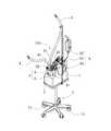
図1に示す本実施形態の呼吸用ガスの加温加湿器100は、例えば、自発呼吸を補助して呼吸障害を治療するためのCPAP装置等に接続されて用いられる。CPAP装置は、持続気道陽圧(CPAP:continuous positive airway pressure)と呼ばれる方式の補助喚起法を用いて患者に治療を施す装置であり、ネーザルプロング、気管挿管チューブ、鼻マスク等の患者インターフェースを介して所定量の酸素と空気との混合ガスからなる呼吸用ガスを患者に供給する。そして、加温加湿器100は、患者に供給される呼吸用ガスを適度の温度及び湿度に維持するために設けられており、CPAP装置から送られる呼吸用ガスは加温加湿器100で加温加湿され、患者に供給されるようになっている。Hereinafter, a breathing gas heating humidifier according to an embodiment of the present invention will be described with reference to the drawings.
The breathing
加温加湿器100は、図1に示すように、制御部等が内蔵された本体1と、本体1と一体に設けられた基台2と、基台2に着脱可能に設けられたチャンバ3と、チャンバ3内に呼吸用ガスを送り込む供給用ホース4と、加温加湿後の呼吸用ガスをチャンバ3から患者インターフェースに送り出すインターフェース接続ホース5と、チャンバ3内に水を供給する給水部6とを備える。
なお、加温加湿器100は、図1に示すように、キャスタ71により移動自在な架台7上に載置されており、架台7とともに全体を移動可能になっている。As shown in FIG. 1, the warming
As shown in FIG. 1, the heating /
基台2は、チャンバ3の下部を嵌め込むことによりチャンバ3を装着可能な凹部21が形成されており、その凹部21の中心部にほぼ円柱状のヒータ22が垂直に立設されている。そして、ヒータ22の表面は、熱伝導性の高い金属(例えば、アルミニウム)からなるヒートシンク23で気密に覆われた構成とされている。 The
チャンバ3は、水を溜める容器部8とその容器部8の上部に取り付けられる蓋部9とから構成されており、容器部8と蓋部9とで構成されるチャンバ3の内部空間に呼吸用ガスを通過させることにより、呼吸用ガスを加温加湿できるようになっている。
なお、チャンバ3の容器部8及び蓋部9は、例えばポリカーボネート樹脂(PC)やPMMA等のアクリル樹脂、ポリスルホン樹脂(PSU)等の透明な樹脂により形成されている。The
The
蓋部9は、基台2に設けられるヒンジ機構部24に着脱可能に設けられるとともに、容器部8に係合するロック部25を有する構成とされている。蓋部9は、ヒンジ機構部24に装着された状態では、ヒンジ機構部24の基端部により本体1に回動自在に支持され、容器部8の上部を開閉できるようになっている。なお、蓋部9は、ヒンジ機構部24から脱離させた状態においても容器部8の上部に着脱することができる。
また、蓋部8には、図1及び図2に示すように、チャンバ3の内部空間に呼吸用ガスを取り込む吸入口41と、チャンバ3内で加湿された呼吸用ガスを外部に導き出す吹出口51と、チャンバ3内に加湿用の水を供給する給水口61とが設けられている。そして、吸入口41は供給用ホース4に接続され、吹出口51はインターフェース接続ホース5に接続され、吸水口61は給水部6に接続されている。The
Further, as shown in FIGS. 1 and 2, the
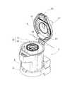
容器部8には、図3及び図4に示すように、底部の中心部に熱伝導性の高い金属(例えば、アルミニウム)からなる加熱板81が設けられている。この加熱板81は、ほぼ円筒スリーブ状の胴体部の上端を天板部に一体に閉塞した形状に形成されている。そして、加熱板81の外周面81aがチャンバ3の内部空間の一部を構成しており、内部空間がリング状の空間に形成されている。また、加熱板81の胴体部の内側には、容器部8を基台2に装着する際にヒートシンク23が挿入されるようになっている。
この場合、ヒートシンク23と加熱板81とは、上方に向かうにしたがって漸次縮径するように若干のテーパ状に形成され、ヒートシンク23の外周面23aと加熱板81の内周面81bとがほぼ同じ傾斜角度に形成されていることにより、ヒートシンク23に加熱板81を嵌合したときに、加熱板81の内周面81bとヒートシンク23の外周面23aとが面接触し、ヒータ22の熱がヒートシンク23を介して加熱板81に円滑に伝えられるようになっている。
そして、この加熱板81の外周面81aに、シート状加湿部材11を有するタワーユニット10が着脱可能に取り付けられるようになっている(図5参照)。As shown in FIGS. 3 and 4, the
In this case, the
And the
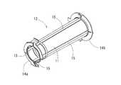
タワーユニット10は、図5から図8に示すように、シート状加湿部材11をほぼ円筒状に支持する枠体12と、シート状加湿部材11の周囲に間隔をあけて設けられる円筒状の仕切り板13との二つの部品を組み合せて構成されている。そして、枠体12と仕切り板13とは、ポリプロピレン等の樹脂により形成されている。
枠体12は、図6に示すように、タワーユニット10の長さ方向の両端に配置される円環部14a,14bを4本の板状部15で繋いだ形状とされており、板状部15の間を塞ぐようにシート状加湿部材11が取り付けられることにより、シート状加湿部材11がほぼ円筒状に保持されている。この場合、加熱板81が若干のテーパ状に形成されていることから、この加熱板81の外周面81aにシート状加湿部材11を緊密接触できるように、枠体12の板状部15及びシート状加湿部材11も加熱板81と同様に、上方に向かうにしたがって漸次縮径するように傾斜を設けた若干のテーパ状に形成されている。As shown in FIGS. 5 to 8, the
As shown in FIG. 6, the
また、仕切り板13は、枠体12の外側を覆う円筒状に形成されており、枠体12と仕切り板13とは、タワーユニット10の両端部で接続されている。
そして、タワーユニット10を容器部8の加熱板81に取り付けた状態では、シート状加湿部材11が加熱板81の外周面81aに面接触するように配置されるとともに、仕切り板13によりチャンバ3の内部空間を内側と外側との二重のリング状空間に区画する。したがって、チャンバ3の内部空間は、図3及び図9に示すように、シート状加湿部材11が配置される内側の加湿空間31と、その加湿空間31に隣接する予熱空間32とに区画されることとなる。Further, the
And in the state which attached the
また、仕切り板13の下部には、予熱空間32と加湿空間31とを連通する連通部33が設けられており、この連通部33は、図9に示すように、水面下に配置される下側連通部34と、この下側連通部34よりも上側に配置され水面wに近接して水面上に開口した上側連通部35とにより構成されている。そして、容器部8内の水は、下側連通部34により、予熱空間32と加湿空間31との間で流通可能とされ、予熱空間32と加湿空間31とに水が同じ水位で貯留される。
なお、図9においては、チャンバ3のみを表示しており、その他の構成部分は非表示にしてある。また、説明を容易にするために、下側連通部34及び上側連通部35を、仕切り板13の周方向の同じ位置に配置している。In addition, a
In FIG. 9, only the
この場合、タワーユニット10の下端部が水に浸漬するとともに、加熱板81の下端部も水に浸漬して設けられるが、タワーユニット10及び加熱板81の大部分は水面上に露出して設けられる。このため、加熱板81によってチャンバ3内の水を加熱することができるとともに、チャンバ3内の空間を温めることができ、チャンバ3の内部空間の湿度を高めることができる。
この際、加熱板81は加湿空間31側に配置され、加湿空間31に溜められた水を直接的に加熱する構成とされているが、前述したように、仕切り板13に下側連通部34を設けているので、チャンバ3内の水を、図9の破線矢印で表されるように、下側連通部34を経由して加湿空間31と予熱空間32との間で流通させることができる。したがって、予熱空間32の水も円滑に加熱することが可能となり、予熱空間32の加湿も円滑に行えるようになっている。In this case, the lower end of the
At this time, the
また、容器部8の中心部に配置された加熱板81により、チャンバ3の内部空間が中心部から周方向に順に加熱されるようになっており、加湿空間31から予熱空間32までがそれぞれの領域で周方向にほぼ均等に加熱される。同様に、中心部に周方向に均等に配置されたシート状加湿部材11により、予熱空間32の周方向で呼吸用ガスの加温加湿を均等に行うことができる。
そして、蓋部9に設けられた吸入口41及び給水口61は、予熱空間32に接続されている。一方、吹出口51は加湿空間31に接続されており、吸入口41から取り込まれた呼吸用ガスは、図9の白抜き矢印で表されるように、上側連通部35(連通部33)を介して予熱空間32から加湿空間31へと移動し、吹出口51から取り出されるようになっている。したがって、呼吸用ガスは、加湿空間31においては、シート状加湿部材11の表面に沿って下から上に向かって流れることとなる。In addition, the internal space of the
The
シート状加湿部材11は、例えばレーヨンやポリエステル、綿などの天然素材により形成された不織布等の吸水性及び通気性に優れた材料が用いられる。このシート状加湿部材11は、前述したようにタワーユニット10を加熱板81に取り付けた状態において、下端部が容器部8内の水に浸漬した状態とされる。これにより、シート状加湿部材11が毛細管現象によって水を吸い上げてシート全域にわたって水が浸透し、水を含んだ湿潤状態が保たれる。 The sheet-
なお、シート状加湿部材11は、枠体12に接着することにより取り付けることができるが、予め枠体12の成形時に金型内にシート状加湿部材11を挿入しておくことで、枠体12と一体化して設けることもできる。 The sheet-shaped
チャンバ3内に水を供給する給水部6は、給水用バッグ62と、この給水用バッグ62とチャンバ3とを接続する給水ホース63と、給水用バッグ62内の水を送水する送水ポンプ64とを備える。
給水ホース63は、チャンバ3の蓋部9に設けられた給水口61に接続されており、チャンバ3内に貯留された水の水位に応じて、給水用バッグ62からチャンバ3内に水が供給されるようになっている。
また、図示は省略するが、加温加湿器100には、チャンバ3内に呼吸用ガスを送り込むためのガス供給機(例えば、CPAP装置)が接続される。A
The
Although not shown, the heating /
次に、加温加湿器100の動作について説明する。
チャンバ3内に呼吸用ガスを供給する前に、給水用バッグ62からチャンバ3内に給水を行う。これにより、シート状加湿部材11の下端部が水面下に浸漬され、シート状加湿部材11が水を吸い上げて湿潤状態となる。そして、この状態でガス供給機を駆動することにより、呼吸用ガスを吸入口41からチャンバ3内に供給する。Next, the operation of the warming
Before supplying the breathing gas into the
呼吸用ガスは、まず予熱空間32に導入され、この予熱空間32に取り込まれた呼吸用ガスは、仕切り板13の上側連通部35に向かって下向きに流れる。この予熱空間32を通過する際に、呼吸用ガスは予備的に加温されるとともに、チャンバ3内の水面w等から予熱空間32内に蒸発している水蒸気により予備的に加湿される。そして、仕切り板13の上側連通部35を通過して加湿空間31へと移動する際に、呼吸用ガスは水面wに近接する上側連通部35を通ることで、水面wに接触して加湿が促進される。
加湿空間31に取り込まれた呼吸用ガスは、流れの向きを上向きに変えて上部の吹出口51に向かって流れる。この際、呼吸用ガスは、加熱板81によって温められた湿潤状態のシート状加湿部材11の表面をなぞるようにその表面に沿って流れることにより、シート状加湿部材11に含まれる水分を気化させ、その水蒸気が取り込まれることで加湿される。そして、加湿された呼吸用ガスは、吹出口51から外部へと取り出される。The breathing gas is first introduced into the preheating
The breathing gas taken into the
なお、シート状加湿部材11は、呼吸用ガスを加湿することで水分が奪われる形となるが、シート状加湿部材11の下端部を水面下に浸漬させているので、呼吸用ガスを加湿すると同時に水を吸い上げて湿潤状態が保たれる。このため、呼吸用ガスを連続して加湿することができる。
また、チャンバ3内の水が消費されることに伴い水位が低下するが、加温加湿器100においては、チャンバ3内の水位に応じて給水部6から水が自動供給されるようになっている。In addition, although the sheet-
In addition, although the water level decreases as the water in the
このように、本実施形態の加温加湿器100によれば、チャンバ3内の水全体を加熱するのではなく、その水に一部を浸漬させて湿潤状態となっているシート状加湿部材11を加熱するので、少ないエネルギーで確実に水を蒸発させることができる。そして、そのシート状加湿部材11の表面に呼吸用ガスを接触させながら通過させることで、少量の水に大量の呼吸用ガスを接触させて蒸発させることができ、水の蒸発速度を増加させることができるとともに、呼吸用ガスに水蒸気を取り込ませ易くすることができ、呼吸用ガスの加湿を円滑に行うことができる。
しかも、シート状加湿部材11は、吸水性に優れるので、加湿空間31に配置される表面から水を蒸発させながら、水に浸漬状態の下端部から速やかに水を上部に吸い上げることができ、水を連続的に蒸発させることができる。Thus, according to the warming /
In addition, since the sheet-
さらに、加熱板81の一部をチャンバ3内の水に浸漬させて配置していることから、加熱板81によってチャンバ3内の水も加熱することができ、チャンバ3内の湿度を高めることができる。また、呼吸用ガスが、この加熱された水の水面に接触することで、呼吸用ガスの加湿が促進される。 Furthermore, since a part of the
また、チャンバ3の内部空間を仕切り板13により区画することで、呼吸用ガスが、加熱板81から離れて配置される予熱空間32から加湿空間31へと流れる通路が形成される。このため、チャンバ3内に取り込まれた呼吸用ガスは、初めに予熱空間32内を通過する際に予備的な加温加湿がなされ、加湿空間31で本格的な加温加湿がなされる。このように、呼吸用ガスは予熱空間32と加湿空間31とで段階的に加温加湿されるようになっていることから、呼吸用ガスのチャンバ3への投入量を増加した際にも、速やかに加温加湿を行うことが可能である。
また、呼吸用ガスが予熱空間32から加湿空間31へと移動する際に仕切り板13に設けられた連通部33を通過することから、呼吸用ガスを水面wに確実に接触させることができ、さらに加湿を促進することができる。Further, by dividing the internal space of the
Further, since the breathing gas passes through the
ところで、チャンバ3内の清浄化のために、チャンバ3を洗浄することが定期的に行われる。加温加湿器100においては、チャンバ3を洗浄する際に、チャンバ3(容器部8及び蓋部9)を基台2から取り外すことができる。そして、ヒータ22は基台2側に取り付けられていることから、チャンバ3の洗浄作業が容易に行えるようになっている。 By the way, in order to clean the inside of the
また、上記実施形態においては、図9に示すように、上側連通部35は、水面上に開口して配置され、すなわちチャンバ3内の水位は上側連通部35よりも下位となるように構成していたが、上側連通部35は、図10に示すように、水面wを跨ぐようにして開口して設けてもよい。
この場合も、上側連通部35は少なくともその一部が水面wから開口する位置に配置されることから、呼吸用ガスが予熱空間32から加湿空間31へと移動する際に、上側連通部35において確実に水面w上を通過させることができ、呼吸用ガスを水面wに接触させて加湿を促進することができる。
また、図10に破線矢印で表されるように、チャンバ3内の水を、下側連通部34と上側連通部35とにより加湿空間31と予熱空間32との間で対流させることができ、予熱空間32の水も円滑に加熱することができる。In the above embodiment, as shown in FIG. 9, the
Also in this case, since the
Further, as represented by a broken line arrow in FIG. 10, the water in the
なお、本発明は上記実施形態に限定されるものではなく、本発明の趣旨を逸脱しない範囲において種々の変更を加えることが可能である。 In addition, this invention is not limited to the said embodiment, A various change can be added in the range which does not deviate from the meaning of this invention.
1 本体
2 基台
3 チャンバ
4 供給用ホース
5 インターフェース接続ホース
6 給水部
7 架台
8 容器部
9 蓋部
10 タワーユニット
11 シート状加湿部材
12 枠体
13 仕切り板
14a,14b 円環部
15 板状部
20 センサ
21 凹部
22 ヒータ
23 ヒートシンク
24 ヒンジ機構部
25 ロック部
31 加湿空間
32 予熱空間
33 連通部
34 下側連通部
35 上側連通部
41 吸入口
51 吹出口
61 給水口
62 給水用バッグ
63 給水ホース
64 送水ポンプ
71 キャスタ
81 加熱板
100 呼吸用ガスの加温加湿器DESCRIPTION OF
Claims (6)
Translated fromJapanesePriority Applications (1)
| Application Number | Priority Date | Filing Date | Title |
|---|---|---|---|
| JP2013051703AJP6091944B2 (en) | 2013-03-14 | 2013-03-14 | Respiratory gas heating humidifier |
Applications Claiming Priority (1)
| Application Number | Priority Date | Filing Date | Title |
|---|---|---|---|
| JP2013051703AJP6091944B2 (en) | 2013-03-14 | 2013-03-14 | Respiratory gas heating humidifier |
Publications (2)
| Publication Number | Publication Date |
|---|---|
| JP2014176476Atrue JP2014176476A (en) | 2014-09-25 |
| JP6091944B2 JP6091944B2 (en) | 2017-03-08 |
Family
ID=51697144
Family Applications (1)
| Application Number | Title | Priority Date | Filing Date |
|---|---|---|---|
| JP2013051703AExpired - Fee RelatedJP6091944B2 (en) | 2013-03-14 | 2013-03-14 | Respiratory gas heating humidifier |
Country Status (1)
| Country | Link |
|---|---|
| JP (1) | JP6091944B2 (en) |
Families Citing this family (1)
| Publication number | Priority date | Publication date | Assignee | Title |
|---|---|---|---|---|
| CN111380134A (en)* | 2020-03-18 | 2020-07-07 | 绍兴安迪斯医疗科技有限公司 | A kind of heating humidifier and heating and humidifying method thereof |
Citations (7)
| Publication number | Priority date | Publication date | Assignee | Title |
|---|---|---|---|---|
| JPS61232862A (en)* | 1985-04-04 | 1986-10-17 | ザ ビーオーシー グループ ピーエルシー | Apparatus for feeding out humidified gas to patient |
| JPS6388346U (en)* | 1986-11-28 | 1988-06-08 | ||
| US4829997A (en)* | 1988-02-18 | 1989-05-16 | University Of Victoria | Portable heat exchanger for inhalation rewarming |
| JPH0394247U (en)* | 1990-01-18 | 1991-09-26 | ||
| JPH05309136A (en)* | 1992-05-08 | 1993-11-22 | Nippon Carbureter Co Ltd | Humidifier for breath gas |
| JPH07227426A (en)* | 1994-02-18 | 1995-08-29 | Toshio Okumura | Silencer of humidifying part of oxygen inhalator |
| JP2014176479A (en)* | 2013-03-14 | 2014-09-25 | Atom Medical Corp | Breathing gas humidifier |
- 2013
- 2013-03-14JPJP2013051703Apatent/JP6091944B2/ennot_activeExpired - Fee Related
Patent Citations (7)
| Publication number | Priority date | Publication date | Assignee | Title |
|---|---|---|---|---|
| JPS61232862A (en)* | 1985-04-04 | 1986-10-17 | ザ ビーオーシー グループ ピーエルシー | Apparatus for feeding out humidified gas to patient |
| JPS6388346U (en)* | 1986-11-28 | 1988-06-08 | ||
| US4829997A (en)* | 1988-02-18 | 1989-05-16 | University Of Victoria | Portable heat exchanger for inhalation rewarming |
| JPH0394247U (en)* | 1990-01-18 | 1991-09-26 | ||
| JPH05309136A (en)* | 1992-05-08 | 1993-11-22 | Nippon Carbureter Co Ltd | Humidifier for breath gas |
| JPH07227426A (en)* | 1994-02-18 | 1995-08-29 | Toshio Okumura | Silencer of humidifying part of oxygen inhalator |
| JP2014176479A (en)* | 2013-03-14 | 2014-09-25 | Atom Medical Corp | Breathing gas humidifier |
Also Published As
| Publication number | Publication date |
|---|---|
| JP6091944B2 (en) | 2017-03-08 |
Similar Documents
| Publication | Publication Date | Title |
|---|---|---|
| US12233214B2 (en) | Portable PAP device with humidification | |
| CN109069785B (en) | Humidifier and breathing assistance device | |
| EP1507568B1 (en) | Device for heating and moistening a breathing gas | |
| CN103260686B (en) | Humidifier system for the gas humidification for being delivered to patient | |
| US20100071692A1 (en) | Spill Resistant Humidifier For Use In A Breathing Assistance System | |
| US20230310788A1 (en) | Heating and humidifying device and heating and humidifying method thereof | |
| HK1214981A1 (en) | A micro-humidifier | |
| EP2244774A1 (en) | Pressure support system with upstream humidifier | |
| WO2015103903A1 (en) | Humidifier for respirator and respirator comprising same | |
| JP2000507470A (en) | Vaporizer, vaporizer usage and liquid vaporization | |
| EP2878327A1 (en) | Apparatus for inhalation of medicine | |
| US20210069454A1 (en) | Humidification system | |
| KR20190030976A (en) | Respiratory gas-humidifier for an artificial respiration apparatus | |
| JP6189057B2 (en) | Respiratory gas heating humidifier | |
| CN102671275B (en) | Humidification apparatus and the ventilation therapy equipment with this humidification apparatus | |
| JP6243480B2 (en) | Respiratory gas heating humidifier | |
| JP6214002B2 (en) | Respiratory gas heating humidifier | |
| JP6091944B2 (en) | Respiratory gas heating humidifier | |
| CN202654514U (en) | Humidification device and ventilation treatment equipment with same | |
| KR20220045934A (en) | Active and passive humidification devices for mounting on patient ventilation circuits | |
| JP6189073B2 (en) | Respiratory gas heating humidifier | |
| JP6249614B2 (en) | Respiratory gas heating humidifier | |
| CN103736193B (en) | A kind of oxygen humidifier with heater | |
| JP2012513236A5 (en) | ||
| JP6111100B2 (en) | Respiratory gas heating humidifier |
Legal Events
| Date | Code | Title | Description |
|---|---|---|---|
| A621 | Written request for application examination | Free format text:JAPANESE INTERMEDIATE CODE: A621 Effective date:20160202 | |
| A131 | Notification of reasons for refusal | Free format text:JAPANESE INTERMEDIATE CODE: A131 Effective date:20161115 | |
| A977 | Report on retrieval | Free format text:JAPANESE INTERMEDIATE CODE: A971007 Effective date:20161121 | |
| A521 | Request for written amendment filed | Free format text:JAPANESE INTERMEDIATE CODE: A523 Effective date:20161226 | |
| TRDD | Decision of grant or rejection written | ||
| A01 | Written decision to grant a patent or to grant a registration (utility model) | Free format text:JAPANESE INTERMEDIATE CODE: A01 Effective date:20170124 | |
| A61 | First payment of annual fees (during grant procedure) | Free format text:JAPANESE INTERMEDIATE CODE: A61 Effective date:20170208 | |
| R150 | Certificate of patent or registration of utility model | Ref document number:6091944 Country of ref document:JP Free format text:JAPANESE INTERMEDIATE CODE: R150 | |
| R250 | Receipt of annual fees | Free format text:JAPANESE INTERMEDIATE CODE: R250 | |
| R250 | Receipt of annual fees | Free format text:JAPANESE INTERMEDIATE CODE: R250 | |
| R250 | Receipt of annual fees | Free format text:JAPANESE INTERMEDIATE CODE: R250 | |
| R250 | Receipt of annual fees | Free format text:JAPANESE INTERMEDIATE CODE: R250 | |
| LAPS | Cancellation because of no payment of annual fees |