Movatterモバイル変換


[0]ホーム

URL:


JP2014175677A - Communication device, program readable by computer, and operation acceptance method for communication device - Google Patents

Communication device, program readable by computer, and operation acceptance method for communication device
Download PDF

Info

Publication number
JP2014175677A
JP2014175677AJP2013043554AJP2013043554AJP2014175677AJP 2014175677 AJP2014175677 AJP 2014175677AJP 2013043554 AJP2013043554 AJP 2013043554AJP 2013043554 AJP2013043554 AJP 2013043554AJP 2014175677 AJP2014175677 AJP 2014175677A
Authority
JP
Japan
Prior art keywords
rich
icon
rich icon
call
displayed
Prior art date
Legal status (The legal status is an assumption and is not a legal conclusion. Google has not performed a legal analysis and makes no representation as to the accuracy of the status listed.)
Pending
Application number
JP2013043554A
Other languages
Japanese (ja)
Inventor
Masaaki Kimura
雅明 木村
Current Assignee (The listed assignees may be inaccurate. Google has not performed a legal analysis and makes no representation or warranty as to the accuracy of the list.)
Nakayo Telecommunications Inc
Original Assignee
Nakayo Telecommunications Inc
Priority date (The priority date is an assumption and is not a legal conclusion. Google has not performed a legal analysis and makes no representation as to the accuracy of the date listed.)
Filing date
Publication date
Application filed by Nakayo Telecommunications IncfiledCriticalNakayo Telecommunications Inc
Priority to JP2013043554ApriorityCriticalpatent/JP2014175677A/en
Publication of JP2014175677ApublicationCriticalpatent/JP2014175677A/en
Pendinglegal-statusCriticalCurrent

Links

Images

Landscapes

Abstract

PROBLEM TO BE SOLVED: To provide a technology for improving user-friendliness by enabling more intuitive operation in a communication device accepting operation using a graphical user interface.SOLUTION: A telephone terminal displays a rich icon 280, which is associated with a telephone number (address information) 281 and is display data including at least either of image information 283 and character information 282 on a communication partner identified by the telephone number 281, on an operation screen. When accepting operation on the rich icon 280 through the operation screen, the telephone terminal controls origination/reception, holding, transfer, and the like of a call for the communication partner identified by the telephone number 281 associated with the rich icon 280, according to a content of operation on the rich icon 280.

Description

Translated fromJapanese

本発明は、GUI(Graphical User Interface、以下、グラフィカルユーザインターフェースと呼称する場合もある)により操作を受け付ける通信装置に関し、特にGUIを介して通信装置に対する操作を受け付ける技術に関する。  The present invention relates to a communication device that accepts an operation through a GUI (Graphical User Interface, hereinafter sometimes referred to as a graphical user interface), and more particularly, to a technology that accepts an operation on a communication device via a GUI.

近年、GUIを備えた通信装置が普及している。例えば、特許文献1に記載のタッチパネルを備えた携帯電話機では、ダイヤルキー等をタッチパネルに表示して、このタッチパネルを介してダイヤル操作を受け付けている。また、特許文献2に記載のタブレットを備えた電話機は、個々の電話番号に対するジェスチャが予め登録されており、タブレットにジェスチャが入力されると、この入力されたジェスチャに対応付けられている電話番号のダイヤル操作を受け付ける。  In recent years, communication devices equipped with a GUI have become widespread. For example, in a mobile phone provided with a touch panel described inPatent Document 1, dial keys and the like are displayed on the touch panel, and a dial operation is received via the touch panel. In addition, in a telephone including a tablet described inPatent Document 2, gestures for individual telephone numbers are registered in advance, and when a gesture is input to the tablet, a telephone number associated with the input gesture is input. The dial operation is accepted.

特開2002−229719号公報JP 2002-229719 A特開2006−93901号公報JP 2006-93901 A

しかしながら、特許文献1に記載の携帯電話機は、ダイヤルキー等の各種キーを物理的に設ける代わりに、これらの各種キーをタッチパネルに表示しているに過ぎず、操作自体は、各種キーが物理的に設けられている既存の電話機と変わらない。また、特許文献2に記載の電話機は、ユーザが電話番号毎にジェスチャを覚えなければならず煩雑である。  However, instead of physically providing various keys such as dial keys, the mobile phone described inPatent Document 1 merely displays these keys on the touch panel, and the operation itself is physically performed by the various keys. It is not different from the existing telephone set in the. Moreover, the telephone set described inPatent Document 2 is complicated because the user must remember a gesture for each telephone number.

本発明は上記事情に鑑みてなされたものであり、本発明の目的は、グラフィカルユーザインターフェースにより操作を受け付ける通信装置において、より直観的な操作を可能とすることにより使い勝手を向上させる技術を提供することにある。  The present invention has been made in view of the above circumstances, and an object of the present invention is to provide a technique for improving usability by enabling a more intuitive operation in a communication device that accepts an operation through a graphical user interface. There is.

上記課題を解決するために、本発明において、グラフィカルユーザインターフェースにより操作を受け付ける通信装置は、アドレス情報に関連付けられ、このアドレス情報により特定される相手の画像情報および文字情報の少なくとも一方を含む表示データであるリッチアイコンをグラフィカルユーザインターフェースに表示する。そして、グラフィカルユーザインターフェースを介してこのリッチアイコンに対する操作を受け付けたならば、このリッチアイコンに関連付けられているアドレス情報により特定される相手に対する通信を、このリッチアイコンに対する操作内容に従って制御する。  In order to solve the above-described problem, in the present invention, a communication device that receives an operation through a graphical user interface is associated with address information, and display data including at least one of image information and character information of a partner specified by the address information Is displayed on the graphical user interface. When an operation for the rich icon is accepted via the graphical user interface, communication with the partner specified by the address information associated with the rich icon is controlled according to the operation content for the rich icon.

例えば、本発明は、グラフィカルユーザインターフェースにより操作を受け付ける通信装置であって、
アドレス情報に関連付けられ、当該アドレス情報により特定される相手の画像情報および文字情報の少なくとも一方を含む表示データであるリッチアイコンを前記グラフィカルユーザインターフェースに表示するリッチアイコン表示手段と、
前記グラフィカルユーザインターフェースに表示されている前記リッチアイコンに対する操作を受け付けるリッチアイコン操作受付手段と、
前記リッチアイコン操作受付手段により前記リッチアイコンに対する操作を受け付けた場合に、当該リッチアイコンに関連付けられている前記アドレス情報により特定される相手に対する通信を、当該リッチアイコンに対する操作内容に従って制御する通信制御手段と、を有する。
For example, the present invention is a communication device that receives an operation through a graphical user interface,
Rich icon display means for displaying on the graphical user interface a rich icon that is display data that is associated with the address information and includes at least one of image information and character information of the other party specified by the address information;
Rich icon operation accepting means for accepting an operation on the rich icon displayed on the graphical user interface;
Communication control means for controlling communication with the partner specified by the address information associated with the rich icon according to the operation content for the rich icon when the rich icon operation accepting means accepts an operation on the rich icon. And having.

本発明によれば、相手に対する通信の各種制御指示を、この相手の画像情報および文字情報の少なくとも一方を含む表示データであるリッチアイコンに対する操作により受け付けるので、より直観的な操作が可能となり、使い勝手を向上させることができる。  According to the present invention, various control instructions for communication to the other party are accepted by an operation on a rich icon which is display data including at least one of the other party's image information and character information. Can be improved.

図1は、本発明の第一実施の形態に係る電話システムの概略構成図である。FIG. 1 is a schematic configuration diagram of a telephone system according to a first embodiment of the present invention.図2は、電話端末2の概略機能構成図である。FIG. 2 is a schematic functional configuration diagram of thetelephone terminal 2.図3はアドレス帳記憶部23の登録内容例を模式的に表した図である。FIG. 3 is a diagram schematically showing an example of registered contents in the addressbook storage unit 23.図4は、GUI部22に表示される操作画面270の一例を示す図である。FIG. 4 is a diagram illustrating an example of theoperation screen 270 displayed on theGUI unit 22.図5は、操作画面270に表示されるリッチアイコン280の一例を示す図である。FIG. 5 is a diagram illustrating an example of therich icon 280 displayed on theoperation screen 270.図6は、電話端末2の通信状態「空」の場合における動作フローを説明するための図である。FIG. 6 is a diagram for explaining an operation flow when the communication state of thetelephone terminal 2 is “empty”.図7は、電話端末2の通信状態「空」の場合における動作フロー(図6の続き)を説明するための図である。FIG. 7 is a diagram for explaining an operation flow (continuation of FIG. 6) when the communication state of thetelephone terminal 2 is “empty”.図8は、電話端末2の通信状態「着信中」の場合における動作フローを説明するための図である。FIG. 8 is a diagram for explaining an operation flow when thetelephone terminal 2 is in the communication state “receiving”.図9は、電話端末2の通信状態「通信中」の場合における動作フローを説明するための図である。FIG. 9 is a diagram for explaining an operation flow when the communication state of thetelephone terminal 2 is “communication”.図10は、電話端末2の通信状態「通信中」の場合における動作フロー(図9の続き)を説明するための図である。FIG. 10 is a diagram for explaining an operation flow (continuation of FIG. 9) when thetelephone terminal 2 is in the communication state “communication”.図11は、電話端末2の通信状態「通信中」の場合における動作フロー(図10の続き)を説明するための図である。FIG. 11 is a diagram for explaining an operation flow (continuation of FIG. 10) when the communication state of thetelephone terminal 2 is “communication”.図12は、電話端末2の通信状態「通信中」の場合における動作フロー(図11の続き)を説明するための図である。FIG. 12 is a diagram for explaining an operation flow (continuation of FIG. 11) in the case where the communication state of thetelephone terminal 2 is “communication”.図13は、電話端末2の通信状態「通信中」の場合における動作フロー(図12の続き)を説明するための図である。FIG. 13 is a diagram for explaining an operation flow (continuation of FIG. 12) in the case where the communication state of thetelephone terminal 2 is “communication”.図14は、発信元のリッチアイコン280が表示された操作画面270の一例を示す図である。FIG. 14 is a diagram illustrating an example of anoperation screen 270 on which arich icon 280 of a transmission source is displayed.図15は、アドレス帳記憶部23に記憶されている発信先候補のリッチアイコン280Aが一覧表示された操作画面270の一例を示す図である。FIG. 15 is a diagram showing an example of anoperation screen 270 on which a list ofrich icons 280A of destination candidates stored in the addressbook storage unit 23 is displayed.図16は、発信先のリッチアイコン280が表示された操作画面270の一例を示す図である。FIG. 16 is a diagram illustrating an example of anoperation screen 270 on which arich icon 280 of a transmission destination is displayed.図17は、通話履歴記憶部24に記憶されている発信先候補のリッチアイコン280Bが一覧表示された操作画面270の一例を示す図である。FIG. 17 is a diagram illustrating an example of anoperation screen 270 on which a list ofrich icons 280B of destination candidates stored in the callhistory storage unit 24 is displayed.図18は、パーク保留中の通話相手のリッチアイコン280Cがパーク保留ウインドウ292に一覧表示された操作画面270の一例を示す図である。FIG. 18 is a diagram illustrating an example of anoperation screen 270 in whichrich icons 280 </ b> C of a call partner who is parked are displayed in a list in thepark hold window 292.図19は、通話中の通話相手のリッチアイコン280が表示された操作画面270の一例を示す図である。FIG. 19 is a diagram illustrating an example of anoperation screen 270 on which arich icon 280 of a call partner during a call is displayed.図20は、ダイヤルパッド294が表示された操作画面270の一例を示す図である。FIG. 20 is a diagram illustrating an example of theoperation screen 270 on which thedial pad 294 is displayed.図21は、保留中の通話相手のリッチアイコン280が表示された操作画面270の一例を示す図である。FIG. 21 is a diagram illustrating an example of anoperation screen 270 on which arich icon 280 of a call partner on hold is displayed.図22は、転送元および転送先のリッチアイコン280が表示された操作画面270の一例を示す図である。FIG. 22 is a diagram illustrating an example of theoperation screen 270 on which the transfer source and transfer destinationrich icons 280 are displayed.図23は、電話会議に参加する通話相手のリッチアイコン280Dが会議スペースウインドウ296に複数表示された操作画面270の一例を示す図である。FIG. 23 is a diagram showing an example of anoperation screen 270 in which a plurality ofrich icons 280D of the other party participating in the conference call are displayed in theconference space window 296.

以下に、本発明の実施の形態について説明する。  Embodiments of the present invention will be described below.

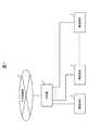
図1は、本実施の形態に係る電話システムの概略構成図である。  FIG. 1 is a schematic configuration diagram of a telephone system according to the present embodiment.

図示するように、本実施の形態の電話システムは、公衆回線網3に接続された主装置1と、主装置1に収容された複数の電話端末2と、を備えて構成される。主装置1は、呼制御処理を行って、電話端末2の発着信、通話、保留、転送等を制御する。一方、電話端末2は、GUI(Graphical User Interface)を備えており、GUIを介して発着信操作、保留操作、転送操作等の電話操作を受け付ける。  As shown in the figure, the telephone system of the present embodiment includes amain device 1 connected to apublic network 3 and a plurality oftelephone terminals 2 accommodated in themain device 1. Themain device 1 performs call control processing to control incoming / outgoing calls, telephone calls, hold, transfer, etc. of thetelephone terminal 2. On the other hand, thetelephone terminal 2 includes a GUI (Graphical User Interface), and accepts telephone operations such as an incoming / outgoing operation, a hold operation, and a transfer operation via the GUI.

つぎに、電話端末2の詳細を説明する。なお、主装置1には既存の一般的な主装置を用いることができるので、その詳細な説明を省略する。  Next, details of thetelephone terminal 2 will be described. In addition, since the existing general main apparatus can be used for themain apparatus 1, the detailed description is abbreviate | omitted.

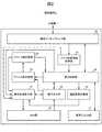
図2は、電話端末2の概略機能構成図である。  FIG. 2 is a schematic functional configuration diagram of thetelephone terminal 2.

電話端末2は、図示するように、通信インターフェース部20と、音声入出力部21と、GUI部22と、アドレス帳記憶部23と、通話履歴記憶部24と、アドレス帳更新部25と、パーク保留情報取得部26と、操作画面表示部27と、操作受付部28と、通信制御部29と、を有している。  As illustrated, thetelephone terminal 2 includes acommunication interface unit 20, a voice input /output unit 21, aGUI unit 22, an addressbook storage unit 23, a callhistory storage unit 24, an address book update unit 25, a park The holdinginformation acquisition unit 26, the operationscreen display unit 27, theoperation reception unit 28, and thecommunication control unit 29 are included.

通信インターフェース部20は、主装置1と通信を行うためのインターフェースである。  Thecommunication interface unit 20 is an interface for communicating with themain apparatus 1.

音声入出力部21は、マイクおよびスピーカを備え、音声の入出力を行う。  The voice input /output unit 21 includes a microphone and a speaker, and performs voice input / output.

GUI部22は、タッチパネルを備え、情報の表示および操作の受付を行う。  TheGUI unit 22 includes a touch panel and displays information and accepts operations.

アドレス帳記憶部23には、アドレス帳データが記憶されている。図3はアドレス帳記憶部23の登録内容例を模式的に表した図である。  The addressbook storage unit 23 stores address book data. FIG. 3 is a diagram schematically showing an example of registered contents in the addressbook storage unit 23.

図示するように、アドレス帳記憶部23には、相手毎にアドレス帳データのレコード230が記憶されている。レコード230は、レコード230を一意に特定するためのIDが登録されたフィールド231と、相手の電話番号(内線番号あるいは外線番号)が登録されたフィールド232と、相手の氏名、所属あるいは勤務先、住所等を含む文字情報が登録されたフィールド233と、相手の写真等を含む画像情報が登録されたフィールド234と、相手に関するメモデータが登録されたフィールド235と、を有する。  As shown in the figure, the addressbook storage unit 23 stores arecord 230 of address book data for each partner. Therecord 230 includes afield 231 in which an ID for uniquely identifying therecord 230 is registered, afield 232 in which the other party's telephone number (extension number or outside line number) is registered, the other party's name, affiliation, or office, It has afield 233 in which character information including an address or the like is registered, afield 234 in which image information including a photo of the other party is registered, and afield 235 in which memo data about the other party is registered.

通話履歴記憶部24には、通話毎に相手の電話番号、通話日時情報(通話日、通話の開始および終了時刻)を含む通話履歴が記憶される。  The callhistory storage unit 24 stores a call history including the other party's telephone number and call date and time information (call date, call start and end time) for each call.

アドレス帳更新部25は、操作受付部28あるいは通信制御部29の指示に従いアドレス帳記憶部23を更新する。  The address book update unit 25 updates the addressbook storage unit 23 in accordance with instructions from theoperation reception unit 28 or thecommunication control unit 29.

パーク保留情報取得部26は、通信インターフェース部20を介して主装置1から、パーク保留中の呼の各々について、呼の中継に用いている外線の回線番号および保留中の通話相手の電話番号等を含むパーク保留情報を取得する。  The park holdinformation acquisition unit 26 receives, from themain device 1 via thecommunication interface unit 20, the line number of the outside line used for call relay and the telephone number of the call partner on hold, etc. Get park hold information including.

操作画面表示部27は、電話操作のための操作画面をGUI部22に表示させる。また、操作画面表示部27は、操作受付部28あるいは通信制御部29の指示に従い、リッチアイコンを生成し、このリッチアイコンを、GUI部22に表示されている操作画面270上に表示する。ここで、リッチアイコンとは、通話相手の画像情報および文字情報の少なくとも一方を含む後述の表示データ(図5参照)であり、アドレス帳記憶部23に記憶されている通話相手のアドレス帳データのレコード230に基づき生成される。  The operationscreen display unit 27 displays an operation screen for telephone operation on theGUI unit 22. In addition, the operationscreen display unit 27 generates a rich icon in accordance with an instruction from theoperation reception unit 28 or thecommunication control unit 29 and displays the rich icon on theoperation screen 270 displayed on theGUI unit 22. Here, the rich icon is display data (see FIG. 5), which will be described later, including at least one of image information and character information of the other party, and the address book data of the other party stored in the addressbook storage unit 23. Generated based on therecord 230.

図4は、GUI部22に表示される操作画面270の一例を示す図である。また、図5は、この操作画面270に表示されるリッチアイコン280の一例を示す図である。  FIG. 4 is a diagram illustrating an example of theoperation screen 270 displayed on theGUI unit 22. FIG. 5 is a diagram illustrating an example of therich icon 280 displayed on theoperation screen 270.

図4に示すように、操作画面270は、アクティブウインドウ271と、非アクティブウインドウ272と、アドレス帳ボタン273と、ダイヤルパッドボタン274と、通話履歴ボタン275と、電話会議ボタン276と、パーク保留ボタン277と、を備えている。  As shown in FIG. 4, theoperation screen 270 includes anactive window 271, aninactive window 272, anaddress book button 273, adial pad button 274, acall history button 275, aconference call button 276, and a park hold button. 277.

アクティブウインドウ271は、発信中もしくは通話中の通話相手のリッチアイコン280を表示するためのウインドウであり、非アクティブウインドウ272は、保留中の通話相手のリッチアイコン280を表示するためのウインドウである。  Theactive window 271 is a window for displaying arich icon 280 of a call partner during a call or a call, and theinactive window 272 is a window for displaying arich icon 280 of a call partner on hold.

アドレス帳ボタン273は、アドレス帳記憶部23に記憶されている通話相手各々のアドレス帳データのレコード230を、リッチアイコン280として一覧表示させるための指示を受け付けるためのボタンである。  Theaddress book button 273 is a button for accepting an instruction to display a list of the addressbook data records 230 stored in the addressbook storage unit 23 asrich icons 280.

ダイヤルパッドボタン274は、電話番号を直接入力するために用いるダイヤルパッドを表示させるための指示を受け付けるためのボタンである。  Thedial pad button 274 is a button for receiving an instruction for displaying a dial pad used for directly inputting a telephone number.

通話履歴ボタン275は、通話履歴を表示させるためのボタンである。  Thecall history button 275 is a button for displaying a call history.

電話会議ボタン276は、電話会議(多者通話)の準備指示を受け付けるためのボタンである。  Theconference call button 276 is a button for accepting an instruction for preparing a conference call (multi-party call).

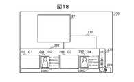
パーク保留ボタン277は、パーク保留情報取得部26によって取得されたパーク保留情報を、リッチアイコン280として一覧表示させるための指示を受け付けるためのボタンである。パーク保留ボタン277上には、パーク保留されている通話相手の数278が表示される(図18参照)。  Thepark hold button 277 is a button for receiving an instruction to display a list of the park hold information acquired by the park holdinformation acquisition unit 26 as arich icon 280. On thepark hold button 277, thenumber 278 of parked call partners is displayed (see FIG. 18).

図5に示すように、リッチアイコン280は、通話相手の電話番号281と、通話相手の氏名、勤務先あるいは所属、住所等を含む文字情報282と、通話相手の写真等を含む画像情報283と、通話相手に関するメモデータ284と、通話相手との通信状態(発信中、着信中、通話中、保留中等)285と、通信状態の経過時間286と、編集ボタン287と、を備えている。ここで、編集ボタン287は、リッチアイコン280に対応する相手のアドレス帳データのレコード230の編集の開始指示を受け付けるためのボタンである。  As shown in FIG. 5, therich icon 280 includes atelephone number 281 of the other party,character information 282 including the name, work or affiliation, address, etc. of the other party, andimage information 283 including a picture of the other party.Memo data 284 regarding the other party, a communication state with the other party (calling, incoming, talking, on hold, etc.) 285, an elapsedtime 286 of the communication state, and anedit button 287. Here, theedit button 287 is a button for accepting an instruction to start editing therecord 230 of the partner address book data corresponding to therich icon 280.

図2に戻って説明を続ける。操作受付部28は、GUI部22に表示されている操作画面270のボタン273〜277に対する操作(タップ操作、スワイプ操作等)を介して操作者から指示を受け付けるとともに、操作画面270上のリッチアイコン280に対する操作(タップ操作、フリック操作、ドラッグアンドドロップ操作等)を介して操作者から電話制御の指示を受け付ける。  Returning to FIG. 2, the description will be continued. Theoperation accepting unit 28 accepts instructions from the operator via operations (tap operation, swipe operation, etc.) on thebuttons 273 to 277 on theoperation screen 270 displayed on theGUI unit 22, and a rich icon on theoperation screen 270. A telephone control instruction is received from the operator via an operation on the H.280 (tap operation, flick operation, drag and drop operation, etc.).

通信制御部29は、操作受付部28あるいは主装置1の指示に従い、主装置1と連携して通話路の接続、切断、保留、転送等の呼制御処理を行う。また、接続中の通話路を介して通話相手から通信インターフェース部20に送られてきた音声データを音声入出力部21から音声出力するとともに、音声入出力部21に音声入力された音声データを、この接続中の通話路を介して通信インターフェース部20から通話相手に送出する。  Thecommunication control unit 29 performs call control processing such as connection, disconnection, hold, transfer, etc. of the communication path in cooperation with themain device 1 in accordance with instructions from theoperation reception unit 28 or themain device 1. The voice input /output unit 21 outputs voice data sent from the other party to thecommunication interface unit 20 via the connected call path, and the voice data input to the voice input /output unit 21 is The data is sent from thecommunication interface unit 20 to the other party via the connected call path.

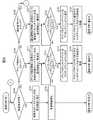
図6および図7は、電話端末2の通信状態「空」の場合における動作フローを説明するための図である。ここで、通信状態「空」とは、発信中、着信中、通話中、および保留中のいずれでもない状態(いわゆる待受け状態)を意味する。  6 and 7 are diagrams for explaining an operation flow when the communication state of thetelephone terminal 2 is “empty”. Here, the communication state “empty” means a state (so-called standby state) that is neither outgoing, incoming, in a call, or on hold.

まず、通信制御部29は、通信インターフェース部20を介して主装置1から、発信元の電話番号を伴う呼の着信通知を受信すると(S100でYES)、その旨を発信元の電話番号とともに操作画面表示部27に通知する。これを受けて、操作画面表示部27は、発信元の電話番号がフィールド232に登録されているレコード230をアドレス帳記憶部23から検索する。そして、図14に示すように、発信元の電話番号と、このレコード230のフィールド233〜235に登録されている文字情報、画像情報、およびメモデータとに基づいて、これらが表示された発信元のリッチアイコン280を生成し、このリッチアイコン280の通信状態285を「着信中」として、GUI部22に表示されている操作画面270上に表示する(S101)。また、通信制御部29は、着信鳴動を開始して(S102)、電話端末2の通信状態を「着信中」に変更し、後述の図8に示すフローに移行する。  First, when thecommunication control unit 29 receives an incoming call notification with a caller's telephone number from themain apparatus 1 via the communication interface unit 20 (YES in S100), thecommunication control unit 29 operates that effect together with the caller's telephone number. Notify thescreen display unit 27. In response to this, the operationscreen display unit 27 searches the addressbook storage unit 23 for therecord 230 in which the caller telephone number is registered in thefield 232. Then, as shown in FIG. 14, based on the telephone number of the caller and the character information, image information, and memo data registered in thefields 233 to 235 of thisrecord 230, the caller from which these are displayed. Therich icon 280 is generated, and thecommunication state 285 of therich icon 280 is displayed as “incoming” on theoperation screen 270 displayed on the GUI unit 22 (S101). Further, thecommunication control unit 29 starts ringing (S102), changes the communication state of thetelephone terminal 2 to “incoming”, and proceeds to the flow shown in FIG.

また、操作受付部28は、GUI部22を介して操作者により操作画面270のアドレス帳ボタン273がタップされたことを検出すると(S110でYES)、その旨を操作画面表示部27に通知する。これを受けて、操作画面表示部27は、図15に示すように、アドレス帳記憶部23に記憶されているレコード230ごとに、フィールド232〜235に登録されている電話番号、文字情報、画像情報、およびメモデータに基づいて、これらが表示されたリッチアイコン280Aを生成し、これらのリッチアイコン280Aが発信先候補各々のリッチアイコン280Aとして一覧表示されたアドレス帳ウインドウ290を操作画面270上に表示する(S111)。ここで、リッチアイコン280Aは、図5に示すリッチアイコン280から一部の情報が省略された簡略形式のものであってもよい。  Further, when theoperation reception unit 28 detects that the operator has tapped theaddress book button 273 on theoperation screen 270 via the GUI unit 22 (YES in S110), theoperation reception unit 28 notifies the operationscreen display unit 27 accordingly. . In response to this, the operationscreen display unit 27, as shown in FIG. 15, for each record 230 stored in the addressbook storage unit 23, telephone numbers, character information, and images registered in thefields 232 to 235. Based on the information and the memo data, arich icon 280A on which these are displayed is generated, and anaddress book window 290 in which theserich icons 280A are listed asrich icons 280A of each destination candidate is displayed on theoperation screen 270. It is displayed (S111). Here, therich icon 280A may have a simplified format in which some information is omitted from therich icon 280 illustrated in FIG.

つぎに、操作受付部28は、アドレス帳ウインドウ290に一覧表示されているいずれかの発信先候補のリッチアイコン280Aが、GUI部22を介して操作者によりドラッグされて操作画面270のアクティブウインドウ271内にドロップされたことを検出すると(S112でYES)、その旨を操作画面表示部27および通信制御部29に通知する。これを受けて、操作画面表示部27は、図16に示すように、操作画面270からアドレス帳ウインドウ290を消去するとともに、アクティブウインドウ271内にドロップされた発信先候補のリッチアイコン280Aに対応するレコード230をアドレス帳記憶部23から検索して、このレコード230のフィールド232〜235に登録された電話番号、文字情報、画像情報、およびメモデータに基づき発信先のリッチアイコン280を生成し、このリッチアイコン280の通信状態285を「発信中」として操作画面270のアクティブウインドウ271内に表示する(S113)。また、通信制御部29は、アクティブウインドウ271内にドロップされた発信先候補のリッチアイコン280Aに対応するレコード230をアドレス帳記憶部23で検索し、このレコード230のフィールド232に登録されている電話番号を発信先番号とする発信要求を、通信インターフェース部20を介して主装置1に送信する(S114)。そして、通信制御部29は、主装置1と連携して呼制御処理を行い、発信先番号により特定される通話相手との通話路を接続する。それから、電話端末2の通信状態を「通信中」に変更するとともに、操作画面表示部27にアクティブウインドウ271内のリッアイコン280の通信状態285を「通話中」に変更させてから、後述の図9〜図13に示すフローに移行する。  Next, theoperation receiving unit 28 drags one of the destination candidaterich icons 280 </ b> A listed in theaddress book window 290 by the operator via theGUI unit 22 to activate theactive window 271 on theoperation screen 270. If it is detected that it has been dropped in (YES in S112), this is notified to the operationscreen display unit 27 and thecommunication control unit 29. In response to this, the operationscreen display unit 27 deletes theaddress book window 290 from theoperation screen 270 and corresponds to therich icon 280A of the destination candidate dropped in theactive window 271 as shown in FIG. Therecord 230 is searched from the addressbook storage unit 23, and arich icon 280 of the destination is generated based on the telephone number, character information, image information, and memo data registered in thefields 232 to 235 of therecord 230. Thecommunication state 285 of therich icon 280 is displayed as “being transmitted” in theactive window 271 of the operation screen 270 (S113). Further, thecommunication control unit 29 searches the addressbook storage unit 23 for therecord 230 corresponding to therich icon 280A of the destination candidate dropped in theactive window 271, and the telephone registered in thefield 232 of this record 230 A call request with the number as the callee number is transmitted to themain apparatus 1 via the communication interface unit 20 (S114). Then, thecommunication control unit 29 performs a call control process in cooperation with themain apparatus 1 and connects a call path with the call partner specified by the destination number. Then, the communication state of thetelephone terminal 2 is changed to “communication”, and thecommunication state 285 of theicon 280 in theactive window 271 is changed to “busy” on the operationscreen display unit 27, and a later-described diagram is displayed. 9 to the flow shown in FIG.

また、操作受付部28は、GUI部22を介して操作者により操作画面270の通話履歴ボタン275がタップされたことを検出すると(S120でYES)、その旨を操作画面表示部27に通知する。これを受けて、操作画面表示部27は、通話履歴記憶部24に記憶されている通話履歴を取得する。そして、取得した通話履歴に記録されている通話相手毎に、通話相手の電話番号がフィールド232に登録されているレコード230をアドレス帳記憶部23から検索する。そして、図17に示すように、検索したレコード230ごとに、フィールド232〜235に登録されている電話番号、文字情報、画像情報、およびメモデータに基づいて、これらが表示されたリッチアイコン280Bを生成し、これらのリッチアイコン280Bが発信先候補各々のリッチアイコン280Bとして、通話履歴の通話日時情報288とともに一覧表示された通話履歴ウインドウ291を操作画面270上に表示する(S121)。ここで、リッチアイコン280Bは、図5に示すリッチアイコン280から一部の情報が省略された簡略形式のものであってもよい。  Further, when detecting that thecall history button 275 on theoperation screen 270 has been tapped by the operator via the GUI unit 22 (YES in S120), theoperation reception unit 28 notifies the operationscreen display unit 27 accordingly. . In response to this, the operationscreen display unit 27 acquires the call history stored in the callhistory storage unit 24. Then, for each call partner recorded in the acquired call history, therecord 230 in which the telephone number of the call partner is registered in thefield 232 is searched from the addressbook storage unit 23. Then, as shown in FIG. 17, for each searchedrecord 230, based on the telephone number, character information, image information, and memo data registered in thefields 232 to 235, arich icon 280B on which these are displayed is displayed. Acall history window 291 that is generated and displayed as a list ofrich icons 280B of eachrich destination 280B together with call date /time information 288 of the call history is displayed on the operation screen 270 (S121). Here, therich icon 280B may have a simplified format in which some information is omitted from therich icon 280 illustrated in FIG.

つぎに、操作受付部28は、通話履歴ウインドウ291に一覧表示されているいずれかの発信先候補のリッチアイコン280Bが、GUI部22を介して操作者によりドラッグされて操作画面270のアクティブウインドウ271内にドロップされたことを検出すると(S122でYES)、その旨を操作画面表示部27および通信制御部29に通知する。これを受けて、操作画面表示部27は、図16に示すように、操作画面270から通話履歴ウインドウ291を消去するとともに、アクティブウインドウ271内にドロップされた発信先候補のリッチアイコン280Bに対応するレコード230をアドレス帳記憶部23から検索して、このレコード230のフィールド232〜235に登録された電話番号、文字情報、画像情報、およびメモデータに基づき発信先のリッチアイコン280を生成し、このリッチアイコン280の通信状態285を「発信中」として操作画面270のアクティブウインドウ271内に表示する(S123)。また、通信制御部29は、アクティブウインドウ271内にドロップされた発信先候補のリッチアイコン280Bに対応するレコード230をアドレス帳記憶部23から検索し、このレコード230のフィールド232に登録されている電話番号を発信先番号とする発信要求を、通信インターフェース部20を介して主装置1に送信する(S124)。そして、通信制御部29は、主装置1と連携して呼制御処理を行い、発信先番号により特定される通話相手との通話路を接続する。それから、電話端末2の通信状態を「通信中」に変更するとともに、操作画面表示部27にアクティブウインドウ271内のリッアイコン280の通信状態285を「通話中」に変更させてから、後述の図9〜図13に示すフローに移行する。  Next, theoperation reception unit 28 drags one of the destination candidaterich icons 280 </ b> B listed in thecall history window 291 by the operator via theGUI unit 22 to activate theactive window 271 on theoperation screen 270. If it is detected that it has been dropped in (YES in S122), this is notified to the operationscreen display unit 27 and thecommunication control unit 29. In response to this, the operationscreen display unit 27 deletes thecall history window 291 from theoperation screen 270 and corresponds to therich icon 280B of the destination candidate dropped in theactive window 271 as shown in FIG. Therecord 230 is searched from the addressbook storage unit 23, and arich icon 280 of the destination is generated based on the telephone number, character information, image information, and memo data registered in thefields 232 to 235 of therecord 230. Thecommunication state 285 of therich icon 280 is displayed as “calling” in theactive window 271 of the operation screen 270 (S123). Further, thecommunication control unit 29 searches the addressbook storage unit 23 for therecord 230 corresponding to therich icon 280B of the destination candidate dropped in theactive window 271, and the telephone registered in thefield 232 of this record 230 A call request with the number as the callee number is transmitted to themain apparatus 1 via the communication interface unit 20 (S124). Then, thecommunication control unit 29 performs a call control process in cooperation with themain apparatus 1 and connects a call path with the call partner specified by the destination number. Then, the communication state of thetelephone terminal 2 is changed to “communication”, and thecommunication state 285 of theicon 280 in theactive window 271 is changed to “busy” on the operationscreen display unit 27, and a later-described diagram is displayed. 9 to the flow shown in FIG.

また、操作受付部28は、GUI部22を介して操作者により操作画面270のパーク保留ボタン277がスワイプされたことを検出すると(S130でYES)、その旨を操作画面表示部27に通知する。これを受けて、操作画面表示部27は、パーク保留されている呼各々のパーク保留情報をパーク保留情報取得部26から取得するとともに、取得したパーク保留情報毎に、パーク保留情報に含まれている保留中の通話相手の電話番号がフィールド232に登録されているレコード230をアドレス帳記憶部23から検索し、保留中の通話相手の電話番号と、このレコード230のフィールド233〜235に登録されている文字情報、画像情報、およびメモデータとに基づいて、保留中の通話相手のリッチアイコン280Cを生成する。そして、図18に示すように、主装置1に収容された外線(回線番号)毎に設けられたパーク保留スロット293の一覧を表示したパーク保留ウインドウ292を操作画面270に表示するとともに、保留中の各通話相手のリッチアイコン280Cを、この保留中の通話相手との通話路に用いている外線に対応付けられたパーク保留スロット293内に表示する(S131)。ここで、リッチアイコン280Cは、図5に示すリッチアイコン280から一部の情報が省略された簡略形式のものであってもよい。  Further, when theoperation reception unit 28 detects that thepark hold button 277 on theoperation screen 270 has been swiped by the operator via the GUI unit 22 (YES in S130), theoperation reception unit 28 notifies the operationscreen display unit 27 accordingly. . In response to this, the operationscreen display unit 27 acquires the park hold information of each parked call from the park holdinformation acquisition unit 26 and is included in the park hold information for each acquired park hold information. Therecord 230 in which the telephone number of the held call partner is registered in thefield 232 is searched from the addressbook storage unit 23, and the telephone number of the call partner on hold and thefields 233 to 235 of thisrecord 230 are registered. Based on the text information, the image information, and the memo data, the rich icon 280C of the call partner on hold is generated. Then, as shown in FIG. 18, apark hold window 292 displaying a list of park holdslots 293 provided for each external line (line number) accommodated in themain device 1 is displayed on theoperation screen 270, and is on hold. Is displayed in thepark hold slot 293 associated with the outside line used for the call path with the call partner on hold (S131). Here, the rich icon 280C may have a simplified format in which some information is omitted from therich icon 280 illustrated in FIG.

つぎに、操作受付部28は、パーク保留ウインドウ292に一覧表示されているいずれかの保留中の通話相手のリッチアイコン280Cが、GUI部22を介して操作者によりドラッグされて操作画面270のアクティブウインドウ271内にドロップされたことを検出すると(S132でYES)、その旨を操作画面表示部27および通信制御部29に通知する。これを受けて、操作画面表示部27は、図19に示すように、操作画面270からパーク保留ウインドウ292を消去するとともに、アクティブウインドウ271内にドロップされたリッチアイコン280Cに対応するレコード230をアドレス帳記憶部23から検索し、このレコード230のフィールド232〜235に登録されている電話番号、文字情報、画像情報、およびメモデータに基づいて通話相手のリッチアイコン280を生成し、このリッチアイコン280の通信状態285を「通話中」として操作画面270のアクティブウインドウ271内に表示する(S133)。また、通信制御部29は、アクティブウインドウ271内にドロップされた保留中の通話相手のリッチアイコン280Cに対応するパーク保留情報に含まれている外線の回線番号の指定を伴うパーク保留解除要求を、通信インターフェース部20を介して主装置1に送信する(S134)。これによりパーク保留が解除され、アクティブウインドウ271内に表示されているリッチアイコン280に対応する通話相手との通話路が接続される。それから、通信制御部29は、電話端末2の通信状態を「通信中」に変更して、後述の図9〜図13に示すフローに移行する。  Next, theoperation accepting unit 28 activates theoperation screen 270 by dragging therich icon 280 </ b> C of one of the on-call parties on the list displayed in thepark hold window 292 by the operator via theGUI unit 22. When it is detected that it has been dropped in the window 271 (YES in S132), this is notified to the operationscreen display unit 27 and thecommunication control unit 29. In response to this, the operationscreen display unit 27 deletes thepark hold window 292 from theoperation screen 270 and addresses the record 230 corresponding to the rich icon 280C dropped in theactive window 271 as shown in FIG. Therich icon 280 of the call partner is generated based on the telephone number, character information, image information, and memo data registered in thefields 232 to 235 of therecord 230 by searching from thebook storage unit 23, and therich icon 280 Is displayed in theactive window 271 of theoperation screen 270 as “busy” (S133). In addition, thecommunication control unit 29 issues a park hold release request with designation of the line number of the outside line included in the park hold information corresponding to the rich icon 280C of the call partner on hold dropped in theactive window 271. It transmits to themain apparatus 1 via the communication interface part 20 (S134). As a result, the park hold is released, and the call path with the call partner corresponding to therich icon 280 displayed in theactive window 271 is connected. Then, thecommunication control unit 29 changes the communication state of thetelephone terminal 2 to “in communication”, and proceeds to the flow shown in FIGS.

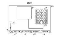
また、操作受付部28は、GUI部22を介して操作者により操作画面270のダイヤルパッドボタン274がタップされたことを検出すると(S140でYES)、その旨を操作画面表示部27に通知する。これを受けて、操作画面表示部27は、図20に示すように、操作者からダイヤル操作を受け付けるためのダイヤルパッド294を操作画面270上に表示する(S141)。  In addition, when theoperation receiving unit 28 detects that the operator has tapped thedial pad button 274 on theoperation screen 270 via the GUI unit 22 (YES in S140), theoperation receiving unit 28 notifies the operationscreen display unit 27 accordingly. . In response to this, the operationscreen display unit 27 displays adial pad 294 for receiving a dial operation from the operator on theoperation screen 270 as shown in FIG. 20 (S141).

つぎに、操作受付部28は、GUI部22を介して操作者によりダイヤルパッド294が操作されて、電話番号が入力されたことを検出すると(S142でYES)、その旨を操作画面表示部27および通信制御部29に通知する。これを受けて、操作画面表示部27は、操作画面270からダイヤルパッド294を消去するとともに、入力された電話番号がフィールド232に登録されているレコード230をアドレス帳記憶部23から検索する。そして、図16に示すように、入力された電話番号と、このレコード230のフィールド233〜235に登録されている文字情報、画像情報、およびメモデータとに基づいて発信先のリッチアイコン280を生成し、このリッチアイコン280の通信状態285を「発信中」として、GUI部22に表示されている操作画面270上のアクティブウインドウ271内に表示する(S143)。また、通信制御部29は、通信インターフェース部20を介して主装置1に、入力された電話番号を発信先番号とする発信要求を送信する(S144)。そして、通信制御部29は、主装置1と連携して呼制御処理を行い、発信先番号により特定される通話相手との通話路を接続する。それから、電話端末2の通信状態を「通信中」に変更するとともに、操作画面表示部27にアクティブウインドウ271内のリッアイコン280の通信状態285を「通話中」に変更させてから、後述の図9〜図13に示すフローに移行する。  Next, when theoperation reception unit 28 detects that thedial number 294 is operated by the operator via theGUI unit 22 and a telephone number is input (YES in S142), the operationscreen display unit 27 notifies that. Then, thecommunication control unit 29 is notified. In response to this, the operationscreen display unit 27 deletes thedial pad 294 from theoperation screen 270 and searches the addressbook storage unit 23 for therecord 230 in which the input telephone number is registered in thefield 232. Then, as shown in FIG. 16, therich icon 280 of the destination is generated based on the input telephone number and the character information, image information, and memo data registered in thefields 233 to 235 of thisrecord 230. Then, thecommunication state 285 of therich icon 280 is set as “calling” and displayed in theactive window 271 on theoperation screen 270 displayed on the GUI unit 22 (S143). In addition, thecommunication control unit 29 transmits a call request with the input telephone number as a call destination number to themain apparatus 1 via the communication interface unit 20 (S144). Then, thecommunication control unit 29 performs a call control process in cooperation with themain apparatus 1 and connects a call path with the call partner specified by the destination number. Then, the communication state of thetelephone terminal 2 is changed to “communication”, and thecommunication state 285 of theicon 280 in theactive window 271 is changed to “busy” on the operationscreen display unit 27, and a later-described diagram is displayed. 9 to the flow shown in FIG.

図8は、電話端末2の通信状態「着信中」の場合における動作フローを説明するための図である。  FIG. 8 is a diagram for explaining an operation flow when thetelephone terminal 2 is in the communication state “receiving”.

まず、操作受付部28は、操作画面270に表示している発信元のリッチアイコン280(図14参照)が、GUI部22を介して操作者によりドラッグされてアクティブウインドウ271内にドロップされたことを検出すると(S200でYES)、その旨を操作画面表示部27および通信制御部29に通知する。これを受けて、操作画面表示部27は、図19に示すように、このリッチアイコン280を、その通信状態285を「通話中」に変更してアクティブウインドウ271内に移動する(S201)。また、通信制御部29は、通信インターフェース部20を介して主装置1に着信応答を送信して、発信元との通話路を接続するとともに(S202)、着信鳴動を停止する(S203)。それから、通信制御部29は、電話端末2の通信状態を「通信中」に変更するとともに、操作画面表示部27にアクティブウインドウ271内のリッアイコン280の通信状態285を「通話中」に変更させてから、後述の図9〜図13に示すフローに移行する。  First, theoperation accepting unit 28 confirms that the sender rich icon 280 (see FIG. 14) displayed on theoperation screen 270 is dragged by the operator via theGUI unit 22 and dropped into theactive window 271. Is detected (YES in S200), the fact is notified to the operationscreen display unit 27 and thecommunication control unit 29. In response to this, the operationscreen display unit 27 moves therich icon 280 into theactive window 271 by changing itscommunication state 285 to “busy” as shown in FIG. 19 (S201). Further, thecommunication control unit 29 transmits an incoming call response to themain apparatus 1 via thecommunication interface unit 20 to connect the call path with the caller (S202) and stop ringing (S203). Then, thecommunication control unit 29 changes the communication state of thetelephone terminal 2 to “in communication”, and causes the operationscreen display unit 27 to change thecommunication state 285 of theicon 280 in theactive window 271 to “busy”. Then, the process proceeds to the flow shown in FIGS.

また、操作受付部28は、操作画面270に表示されている発信元のリッチアイコン280が、GUI部22を介して操作者によりフリックされたことを検出すると(S210でYES)、その旨を操作画面表示部27および通信制御部29に通知する。これを受けて、操作画面表示部27は、操作画面270から発信元のリッチアイコン280を消去する(S211)。また、通信制御部29は、通信インターフェース部20を介して主装置1に着信拒否を送信するとともに(S212)、着信鳴動を停止する(S213)。それから、通信制御部29は、通話履歴記憶部24に記憶されている通話履歴を更新した後(S214)、電話端末2の通信状態を「空」に変更して、前述の図6および図7に示すフローに移行する。  Further, when theoperation reception unit 28 detects that therich icon 280 of the transmission source displayed on theoperation screen 270 is flicked by the operator via the GUI unit 22 (YES in S210), theoperation reception unit 28 operates to that effect. Thescreen display unit 27 and thecommunication control unit 29 are notified. In response to this, the operationscreen display unit 27 deletes therich icon 280 of the caller from the operation screen 270 (S211). In addition, thecommunication control unit 29 transmits an incoming call rejection to themain apparatus 1 via the communication interface unit 20 (S212) and stops ringing (S213). Then, after updating the call history stored in the call history storage unit 24 (S214), thecommunication control unit 29 changes the communication state of thetelephone terminal 2 to “empty”, and the above-described FIG. 6 and FIG. Transition to the flow shown in.

また、通信制御部29は、通信インターフェース部20を介して主装置1から着信中の呼について切断通知を受信すると(S220でYES)、その旨を操作画面表示部27および通信制御部29に通知する。これを受けて、操作画面表示部27は、操作画面270から発信元のリッチアイコン280を消去する(S221)。また、通信制御部29は、着信鳴動を停止するとともに(S222)、通話履歴記憶部24に記憶されている通話履歴を更新する(S223)。その後、通信制御部29は、電話端末2の通信状態を「空」に変更して、前述の図6および図7に示すフローに移行する。  In addition, when thecommunication control unit 29 receives a disconnection notification for an incoming call from themain apparatus 1 via the communication interface unit 20 (YES in S220), thecommunication control unit 29 notifies the operationscreen display unit 27 and thecommunication control unit 29 accordingly. To do. In response to this, the operationscreen display unit 27 deletes therich icon 280 of the caller from the operation screen 270 (S221). Thecommunication control unit 29 stops ringing (S222) and updates the call history stored in the call history storage unit 24 (S223). Thereafter, thecommunication control unit 29 changes the communication state of thetelephone terminal 2 to “empty” and proceeds to the flow shown in FIG. 6 and FIG.

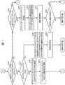
図9〜図13は、電話端末2の通信状態「通信中」の場合における動作フローを説明するための図である。ここで、通信状態「通信中」とは、通話中および保留中の少なくとも一方の状態を意味する。  9 to 13 are diagrams for explaining an operation flow when the communication state of thetelephone terminal 2 is “communication”. Here, the communication state “communication” means at least one of a state during a call and a state where the communication is on hold.

まず、通信制御部29は、通信インターフェース部20を介して主装置1から通話中の通話相手の切断通知を受信すると(S300でYES)、その旨を操作画面表示部27および通信制御部29に通知する。これを受けて、操作画面表示部27は、アクティブウインドウ271からリッチアイコン280を消去する(S301)。また、通信制御部29は、通話中の通話相手との通話路を切断するとともに(S302)、通話履歴記憶部24に記憶されている通話履歴を更新する(S303)。それから、通信制御部29は、非アクティブウインドウ272内にリッチアイコン280が表示されているならば、つまり保留中の通話相手が存在するならば(S304でYES)、S300に戻り、保留中の通話相手が存在しないならば(S304でNO)、電話端末2の通信状態を「空」に変更して、前述の図6および図7に示すフローに移行する。  First, when thecommunication control unit 29 receives from the main device 1 a disconnection notification of the other party on the call via the communication interface unit 20 (YES in S300), thecommunication control unit 29 notifies the operationscreen display unit 27 and thecommunication control unit 29 to that effect. Notice. In response to this, the operationscreen display unit 27 deletes therich icon 280 from the active window 271 (S301). Further, thecommunication control unit 29 disconnects the call path with the other party during the call (S302), and updates the call history stored in the call history storage unit 24 (S303). Then, if therich icon 280 is displayed in theinactive window 272, that is, if there is a call partner on hold (YES in S304), thecommunication control unit 29 returns to S300 to call on hold. If there is no other party (NO in S304), the communication state of thetelephone terminal 2 is changed to “empty”, and the process proceeds to the flow shown in FIG. 6 and FIG.

また、通信制御部29は、通信インターフェース部20を介して主装置1から保留中の通話相手の切断通知を受信すると(S310でYES)、その旨を操作画面表示部27および通信制御部29に通知する。これを受けて、操作画面表示部27は、非アクティブウインドウ272からリッチアイコン280を消去する(S311)。また、通信制御部29は、通話履歴記憶部24に記憶されている通話履歴を更新し(S312)、その後、アクティブウインドウ271内にリッチアイコン280が表示されているならば、つまり通話中の通話相手が存在するならば(S313でYES)、S300に戻り、通話中の相手が存在しないならば(S313でNO)、電話端末2の通信状態を「空」に変更して、前述の図6および図7に示すフローに移行する。  In addition, when thecommunication control unit 29 receives a disconnection notice of the call partner on hold from themain apparatus 1 via the communication interface unit 20 (YES in S310), thecommunication control unit 29 notifies the operationscreen display unit 27 and thecommunication control unit 29 to that effect. Notice. In response to this, the operationscreen display unit 27 deletes therich icon 280 from the inactive window 272 (S311). In addition, thecommunication control unit 29 updates the call history stored in the call history storage unit 24 (S312), and thereafter, if therich icon 280 is displayed in theactive window 271, that is, the call during a call. If the other party exists (YES in S313), the process returns to S300, and if there is no other party in the call (NO in S313), the communication state of thetelephone terminal 2 is changed to “empty”, and the above-described FIG. And it transfers to the flow shown in FIG.

また、操作受付部28は、アクティブウインドウ271内にリッチアイコン280が表示されていない状態(通話中でなく、かつ保留中の状態)において(S320でYES)、非アクティブウインドウ272内の保留中の通話相手のリッチアイコン280(図21参照)が、GUI部22を介して操作者によりドラッグされてアクティブウインドウ271内にドロップされたことを検出すると(S321でYES)、その旨を操作画面表示部27および通信制御部29に通知する。これを受けて、操作画面表示部27は、図19に示すように、この保留中の通話相手のリッチアイコン280を、その通信状態285を「通話中」に変更し、非アクティブウインドウ272内からアクティブウインドウ271内に移動する(S322)。また、通信制御部29は、ドロップされたリッチアイコン280に対応する保留中の通話相手の保留を解除して通話路を接続する(S323)。その後、S300に戻る。  Further, theoperation reception unit 28 is in a state where therich icon 280 is not displayed in the active window 271 (in a state where the call is not in progress and is on hold) (YES in S320), and theoperation reception unit 28 is on hold in theinactive window 272. When it is detected that the rich icon 280 (refer to FIG. 21) of the other party is dragged by the operator via theGUI unit 22 and dropped into the active window 271 (YES in S321), this is indicated on the operation screen display unit. 27 and thecommunication control unit 29. In response to this, the operationscreen display unit 27 changes therich icon 280 of the call partner on hold, changes itscommunication state 285 to “busy”, as shown in FIG. It moves into the active window 271 (S322). Further, thecommunication control unit 29 releases the hold of the call partner on hold corresponding to the droppedrich icon 280 and connects the call path (S323). Thereafter, the process returns to S300.

また、操作受付部28が、アクティブウインドウ271内にリッチアイコン280が表示されていない状態において(S320でYES)、操作画面270のアドレス帳ボタン273がタップされたことを検出すると(S324でYES)、操作受付部28および通信制御部29が前述の図6に示すS111〜S114と同様な処理を実行し(S325)、それからS300に戻る。  In addition, when theoperation reception unit 28 detects that theaddress book button 273 on theoperation screen 270 is tapped in the state where therich icon 280 is not displayed in the active window 271 (YES in S320) (YES in S324). Then, theoperation accepting unit 28 and thecommunication control unit 29 execute the same processing as S111 to S114 shown in FIG. 6 described above (S325), and then returns to S300.

また、操作受付部28が、アクティブウインドウ271内にリッチアイコン280が表示されていない状態において(S320でYES)、操作画面270の通話履歴ボタン275がタップされたことを検出すると(S326でYES)、操作受付部28および通信制御部29が前述の図6に示すS121〜S124と同様な処理を実行し(S327)、それからS300に戻る。  Further, when theoperation reception unit 28 detects that thecall history button 275 on theoperation screen 270 is tapped in the state where therich icon 280 is not displayed in the active window 271 (YES in S320), theoperation accepting unit 28 determines YES in S326. Then, theoperation accepting unit 28 and thecommunication control unit 29 execute the same processing as S121 to S124 shown in FIG. 6 (S327), and then returns to S300.

また、操作受付部28が、アクティブウインドウ271内にリッチアイコン280が表示されていない状態において(S320でYES)、操作画面270のパーク保留ボタン277がスワイプされたことを検出すると(S328でYES)、操作受付部28および通信制御部29が、前述の図7に示すS131〜S134と同様な処理を実行し(S329)、それからS300に戻る。  In addition, when theoperation reception unit 28 detects that thepark hold button 277 on theoperation screen 270 is swiped in a state where therich icon 280 is not displayed in the active window 271 (YES in S320), the determination is YES in S328. Then, theoperation accepting unit 28 and thecommunication control unit 29 execute the same processing as S131 to S134 shown in FIG. 7 (S329), and then returns to S300.

また、操作受付部28が、アクティブウインドウ271内にリッチアイコン280が表示されていない状態において(S320でYES)、操作画面270のダイヤルパッドボタン274がタップされたことを検出すると(S330でYES)、操作受付部28および通信制御部29が、前述の図7に示すS141〜S144と同様な処理を実行し(S331)、それからS300に戻る。  In addition, when theoperation reception unit 28 detects that thedial pad button 274 on theoperation screen 270 is tapped in the state where therich icon 280 is not displayed in the active window 271 (YES in S320) (YES in S330). Then, theoperation accepting unit 28 and thecommunication control unit 29 execute the same processing as S141 to S144 shown in FIG. 7 (S331), and then returns to S300.

一方、操作受付部28は、アクティブウインドウ271内に通話中の通話相手のリッチアイコン280が表示されている状態(通話中の状態)において(S320でNO)、アクティブウインドウ271内の通話相手のリッチアイコン280(図19参照)が、GUI部22を介して操作者によりドラッグされて非アクティブウインドウ272内にドロップされたことを検出すると(S340でYES)、その旨を操作画面表示部27および通信制御部29に通知する。  On the other hand, when therich icon 280 of the other party on the call is displayed in the active window 271 (the state during the call) (NO in S320), theoperation accepting unit 28 is rich in the other party on theactive window 271. When it is detected that the icon 280 (see FIG. 19) is dragged by the operator via theGUI unit 22 and dropped into the inactive window 272 (YES in S340), the operationscreen display unit 27 and the communication are notified to that effect. Notify thecontrol unit 29.

これを受けて、操作画面表示部27は、アクティブウインドウ271内のリッチアイコン280が非アクティブウインドウ272にドロップされる直前に、非アクティブウインドウ272内に他のリッチアイコン280が表示されていないならば、つまり保留中の通話相手が存在しないならば(S341でYES)、図21に示すように、このドロップされた通話相手のリッチアイコン280を、その通信状態285を「保留中」に変更してアクティブウインドウ271内から非アクティブウインドウ272内に移動する(S342)。また、通信制御部29は、ドロップされたリッチアイコン280に対応する通話相手との通話を保留し(S343)、その後、S300に戻る。  In response to this, the operationscreen display unit 27 determines that anotherrich icon 280 is not displayed in theinactive window 272 immediately before therich icon 280 in theactive window 271 is dropped on theinactive window 272. That is, if there is no call partner on hold (YES in S341), as shown in FIG. 21, therich icon 280 of the dropped call partner is changed to “pending” thecommunication state 285. It moves from theactive window 271 to the inactive window 272 (S342). In addition, thecommunication control unit 29 holds the call with the call partner corresponding to the dropped rich icon 280 (S343), and then returns to S300.

一方、アクティブウインドウ271内のリッチアイコン280が非アクティブウインドウ272にドロップされる直前に、非アクティブウインドウ272内に他のリッチアイコン280が表示されていたならば、つまり保留中の通話相手が存在するならば(S341でNO)、図22に示すように、アクティブウインドウ271内から非アクティブウインドウ272内にドロップされた通話相手のリッチアイコン280と、非アクティブウインドウ272内に表示されている他の保留中の通話相手のリッチアイコン280とを操作画面270に並べて表示するとともに、転送を開始するためのダイアログボックス295を操作画面270に表示する。通信制御部29は、GUI部22および操作受付部28を介して、この操作画面270上で操作者が入力した転送開始指示を受け付けたならば、操作画面270に並列表示された各リッチアイコン280に対応する通話相手の電話番号の指定を伴う転送要求を、通信インターフェース部20を介して主装置1に送信する。これにより、アクティブウインドウ271内のリッチアイコン280に対応する通話中の通話相手の呼が、非アクティブウインドウ272内の他のリッチアイコン280に対応する保留中の通話相手に転送される(S344)。それから、操作画面表示部27は、操作画面270に並列表示された各リッチアイコン280を消去し、通信制御部29は、通話履歴記憶部24に記憶されている通話履歴を更新し(S345)、その後、電話端末2の通信状態を「空」に変更して、前述の図6および図7に示すフローに移行する。  On the other hand, if anotherrich icon 280 is displayed in theinactive window 272 immediately before therich icon 280 in theactive window 271 is dropped on theinactive window 272, that is, there is a call partner on hold. If so (NO in S341), as shown in FIG. 22, therich icon 280 of the other party that has been dropped from theactive window 271 into theinactive window 272, and another hold displayed in the inactive window 272 Arich icon 280 of the calling party is displayed side by side on theoperation screen 270, and a dialog box 295 for starting transfer is displayed on theoperation screen 270. If thecommunication control unit 29 receives a transfer start instruction input by the operator on theoperation screen 270 via theGUI unit 22 and theoperation reception unit 28, therich icons 280 displayed in parallel on theoperation screen 270 are displayed. A transfer request accompanied with designation of the telephone number of the other party corresponding to is transmitted to themain apparatus 1 via thecommunication interface unit 20. Thereby, the call of the other party on the call corresponding to therich icon 280 in theactive window 271 is transferred to the other party on hold corresponding to the otherrich icon 280 in the inactive window 272 (S344). Then, the operationscreen display unit 27 deletes therich icons 280 displayed in parallel on theoperation screen 270, and thecommunication control unit 29 updates the call history stored in the call history storage unit 24 (S345). Thereafter, the communication state of thetelephone terminal 2 is changed to “empty”, and the process proceeds to the flow shown in FIG. 6 and FIG.

また、操作受付部28は、アクティブウインドウ271内に通話中の通話相手のリッチアイコン280が表示されている状態において(S320でNO)、アクティブウインドウ271内のリッチアイコン280(図19参照)がフリックされたことを検出すると(S350でYES)、その旨を操作画面表示部27および通信制御部29に通知する。これを受けて、操作画面表示部27は、アクティブウインドウ271からリッチアイコン280を消去する(S351)。また、通信制御部29は、フリックされたリッチアイコン280に対応する通話中の通話相手との通話路の切断要求を、通信インターフェース部20を介して主装置1に送信して、この通話路を切断するとともに(S352)、通話履歴記憶部24に記憶されている通話履歴を更新する(S353)。それから、通信制御部29は、非アクティブウインドウ272内にリッチアイコン280が表示されているならば、つまり保留中の通話相手が存在するならば(S354でYES)、S300に戻り、保留中の通話相手が存在しないならば(S354でNO)、電話端末2の通信状態を「空」に変更して、前述の図6および図7に示すフローに移行する。  Further, theoperation accepting unit 28 flicks the rich icon 280 (see FIG. 19) in theactive window 271 in a state where therich icon 280 of the other party on the call is displayed in the active window 271 (NO in S320). If it is detected (YES in S350), this is notified to the operationscreen display unit 27 and thecommunication control unit 29. In response to this, the operationscreen display unit 27 deletes therich icon 280 from the active window 271 (S351). In addition, thecommunication control unit 29 transmits a call path disconnection request with the other party during a call corresponding to the flickedrich icon 280 to themain apparatus 1 via thecommunication interface unit 20, and uses this call path. While disconnecting (S352), the call history stored in the callhistory storage unit 24 is updated (S353). Then, if therich icon 280 is displayed in theinactive window 272, that is, if there is a call partner on hold (YES in S354), thecommunication control unit 29 returns to S300 and holds the call on hold. If there is no other party (NO in S354), the communication state of thetelephone terminal 2 is changed to “empty”, and the process proceeds to the flow shown in FIG. 6 and FIG.

また、操作受付部28は、アクティブウインドウ271内に通話中の通話相手のリッチアイコン280が表示されている状態において(S320でNO)、操作画面270のパーク保留ボタン277がスワイプされたことを検出すると(S360でYES)、その旨を操作画面表示部27に通知する。これを受けて、操作画面表示部27は、パーク保留情報取得部26からパーク保留されている各通話相手のパーク保留情報を取得するとともに、取得したパーク保留情報毎に、パーク保留情報に含まれている電話番号がフィールド232に登録されているレコード230をアドレス帳記憶部23から検索し、この電話番号と、検索したレコード230のフィールド233〜235に登録されている文字情報、画像情報、およびメモデータとに基づいて、パーク保留されている通話相手のリッチアイコン280Cを生成する。そして、図7のS131と同様、図18に示すように、主装置1に収容された外線毎に設けられたパーク保留スロット293が一覧表示されたパーク保留ウインドウ292を操作画面270に表示するとともに、パーク保留されている各通話相手のリッチアイコン280Cを、この通話相手との通話路に用いている外線に対応付けられたパーク保留スロット293内に表示する(S361)。  In addition, theoperation reception unit 28 detects that thepark hold button 277 on theoperation screen 270 is swiped in a state where therich icon 280 of the other party on the call is displayed in the active window 271 (NO in S320). Then (YES in S360), this is notified to the operationscreen display unit 27. In response, the operationscreen display unit 27 acquires the park hold information of each call partner parked from the park holdinformation acquisition unit 26 and is included in the park hold information for each acquired park hold information. Arecord 230 in which the telephone number is registered in thefield 232 is searched from the addressbook storage unit 23, and the telephone number and the character information, image information, registered in thefields 233 to 235 of the searchedrecord 230, and Based on the memo data, a rich icon 280C of the call partner who is parked is generated. As in S131 of FIG. 7, as shown in FIG. 18, apark hold window 292 displaying a list of park holdslots 293 provided for each external line accommodated in themain apparatus 1 is displayed on theoperation screen 270. Then, the rich icon 280C of each call partner who is parked is displayed in thepark hold slot 293 associated with the outside line used for the call path with this call partner (S361).

つぎに、操作受付部28は、アクティブウインドウ271内の通話中の通話相手のリッチアイコン280がドラッグされて、リッチアイコン280Cが表示されていないパーク保留スロット293内にドロップされたことを検出すると(S362でYES)、その旨を操作画面表示部27および通信制御部29に通知する。これを受けて、操作画面表示部27は、アクティブウインドウ271からドロップ先のパーク保留スロット293に通話中の通話相手のリッチアイコン280を移動する(S363)。また、通信制御部29は、アクティブウインドウ271内からパーク保留スロット293内にドロップされたリッチアイコン280に対応する通話中の通話相手の電話番号およびドロップ先のパーク保留スロット293に対応する外線の回線番号の指示を伴うパーク保留要求を、通信インターフェース部20を介して主装置1に送信して、この通話中の通話相手をパーク保留させる(S364)。それから、通信制御部29は、非アクティブウインドウ272内にリッチアイコン280が表示されている、つまり保留中の通話相手が存在するならば(S365でYES)、S300に戻り、保留中の通話相手が存在しないならば(S365でNO)、電話端末2の通信状態を「空」に変更して、前述の図6および図7に示すフローに移行する。  Next, when theoperation accepting unit 28 detects that therich icon 280 of the other party in the call in theactive window 271 is dragged and dropped into thepark holding slot 293 where the rich icon 280C is not displayed ( In step S362, YES), that effect is notified to the operationscreen display unit 27 and thecommunication control unit 29. In response to this, the operationscreen display unit 27 moves therich icon 280 of the calling party from theactive window 271 to thepark destination slot 293 to be dropped (S363). In addition, thecommunication control unit 29 sets the telephone number of the other party in the call corresponding to therich icon 280 dropped in thepark hold slot 293 from theactive window 271 and the external line corresponding to thepark hold slot 293 to which the call is dropped. A park hold request with a number instruction is transmitted to themain apparatus 1 via thecommunication interface unit 20 to park the call partner during the call (S364). Then, if therich icon 280 is displayed in theinactive window 272, that is, if there is a call partner on hold (YES in S365), thecommunication control unit 29 returns to S300, and the call partner on hold is If it does not exist (NO in S365), the communication state of thetelephone terminal 2 is changed to “empty”, and the process proceeds to the flow shown in FIG. 6 and FIG.

また、操作受付部28は、アクティブウインドウ271内に通話中の通話相手のリッチアイコン280が表示されており(S320でNO)、かつ操作画面270に会議スペースウインドウ296(図23参照)が表示されていない状態において(S370でNO)、操作画面27の電話会議ボタン276がタップされたことを検出すると(S371でYES)、その旨を操作画面表示部27に通知する。これを受けて、操作画面表示部27は、図23に示すように、電話会議(多者通話)に参加する通話相手のリッチアイコン280Dの一覧を表示するための会議スペースウインドウ296を操作画面270上に表示する(S372)。ここで、リッチアイコン280Dは、図5に示すリッチアイコン280から一部の情報が省略された簡略形式のものであってもよい。  Further, theoperation accepting unit 28 displays therich icon 280 of the other party in the call in the active window 271 (NO in S320), and the conference space window 296 (see FIG. 23) is displayed on theoperation screen 270. If it is determined that thetelephone conference button 276 on theoperation screen 27 has been tapped (YES in S371), the operationscreen display unit 27 is notified of this fact. In response to this, as shown in FIG. 23, the operationscreen display unit 27 displays aconference space window 296 for displaying a list ofrich icons 280D of the other party participating in the conference call (multi-party call). It is displayed above (S372). Here, therich icon 280D may have a simplified format in which some information is omitted from therich icon 280 illustrated in FIG.

また、操作受付部28は、アクティブウインドウ271内に通話中の通話相手のリッチアイコン280が表示されており(S320でNO)、かつ操作画面270に会議スペースウインドウ296が表示されている状態において(S370でYES)、アクティブウインドウ271内の通話中の通話相手のリッチアイコン280がドラッグされて会議スペースウインドウ296内にドロップされたことを検出すると(S380でYES)、その旨を操作画面表示部27および通信制御部29に通知する。これを受けて、操作画面表示部27は、図23に示すように、アクティブウインドウ271から通話中の通話相手のリッチアイコン280を、電話会議に参加する通話相手のリッチアイコン280Dとして会議スペースウインドウ296内に移動する(S381)。また、通信制御部29は、アクティブウインドウ271内から会議スペースウインドウ296内にドロップされたリッチアイコン280Dに対応する通話中の通話相手との通話を保留する(S382)。  Further, theoperation accepting unit 28 is in a state in which therich icon 280 of the other party in a call is displayed in the active window 271 (NO in S320) and theconference space window 296 is displayed on the operation screen 270 ( If it is detected that therich icon 280 of the calling party in theactive window 271 is dragged and dropped in the conference space window 296 (YES in S380), the operationscreen display unit 27 notifies that. Then, thecommunication control unit 29 is notified. In response to this, the operationscreen display unit 27, as shown in FIG. 23, sets therich icon 280 of the other party on the call from theactive window 271 as therich icon 280D of the other party to participate in the conference call. (S381). In addition, thecommunication control unit 29 puts the call on hold with the call partner corresponding to therich icon 280D dropped from theactive window 271 into the conference space window 296 (S382).

その後、操作受付部28は、会議スペースウインドウ296内の会議開始ボタン297がタップされることにより、操作者から電話会議開始指示を受け付けると(S383でYES)、会議スペースウインドウ296内にリッチアイコン280Dが複数表示されているならば(S384でYES)、通信制御部29に、会議スペースウインドウ296内に表示されている各リッチアイコン280Dに対応する通話相手の電話番号を通知して、多者通話の開始を指示する。これを受けて、通信制御部29は、会議スペースウインドウ296内に表示されている各リッチアイコン280Dに対応する通話相手の保留を解除して、これらの通話相手と多者通話(電話会議)を開始する(S385)。  Thereafter, when theconference reception button 297 in theconference space window 296 is tapped to accept a conference call start instruction from the operator (YES in S383), theoperation reception unit 28 receives arich icon 280D in theconference space window 296. Are displayed (YES in S384), thecommunication control unit 29 is notified of the telephone number of the other party corresponding to eachrich icon 280D displayed in theconference space window 296, and the multi-party call Instruct the start of. In response to this, thecommunication control unit 29 releases the hold of the call partner corresponding to eachrich icon 280D displayed in theconference space window 296, and makes a multi-party call (conference call) with these call partners. Start (S385).

その後、操作受付部28は、会議スペースウインドウ296内の会議終了ボタン298がタップされることにより、操作者から電話会議終了指示を受け付けると(S386でYES)、その旨を、操作画面表示部27および通信制御部29に通知する。これを受けて、操作画面表示部27は、操作画面270から会議スペースウインドウ296を消去する。また、通信制御部29は、多者通話を終了して、多者通話に参加した通話相手各々との通話路を切断する(S387)。それから、通信制御部29は、通話履歴記憶部24に記憶されている通話履歴を更新するとともに(S389)、非アクティブウインドウ272内に保留中の通話相手のリッチアイコン280が表示されているならば、つまり保留中の通話相手が存在するならば(S390でYES)、S300に戻り、保留中の通話相手が存在しないならば(S390でNO)、電話端末2の通信状態を「空」に変更して、前述の図6および図7に示すフローに移行する。  Thereafter, when theconference end button 298 in theconference space window 296 is tapped and theoperation reception unit 28 receives a conference call end instruction from the operator (YES in S386), the operationscreen display unit 27 notifies that. Then, thecommunication control unit 29 is notified. In response to this, the operationscreen display unit 27 deletes theconference space window 296 from theoperation screen 270. In addition, thecommunication control unit 29 ends the multi-party call and disconnects the call path with each of the other parties who have joined the multi-party call (S387). Then, thecommunication control unit 29 updates the call history stored in the call history storage unit 24 (S389), and if therich icon 280 of the call partner on hold is displayed in theinactive window 272. That is, if there is a call partner on hold (YES in S390), the process returns to S300, and if there is no call partner on hold (NO in S390), the communication state of thetelephone terminal 2 is changed to “empty”. Then, the process proceeds to the flow shown in FIG. 6 and FIG.

以上、本発明の一実施の形態について説明した。  The embodiment of the present invention has been described above.

本実施の形態において、電話端末2は、アドレス情報(電話番号)に関連付けられ、このアドレス情報により特定される通話相手の画像情報および文字情報の少なくとも一方を含む表示データであるリッチアイコン280をGUI部22の操作画面270に表示する。そして、操作画面270を介して、このリッチアイコン280に対する操作を受け付けたならば、このリッチアイコン280に関連付けられているアドレス情報により特定される通話相手に対する電話を、このリッチアイコン280に対する操作内容に従って制御する。  In the present embodiment, thetelephone terminal 2 displays arich icon 280, which is display data associated with address information (telephone number) and includes at least one of image information and character information of a calling party specified by the address information, on the GUI. Displayed on theoperation screen 270 of theunit 22. Then, if an operation for therich icon 280 is accepted via theoperation screen 270, a call to the calling party specified by the address information associated with therich icon 280 is made according to the operation content for therich icon 280. Control.

例えば、リッチアイコン280がドラッグされ、操作画面270に表示されているアクティブウインドウ271内にドロップされた場合、このリッチアイコン280に関連付けられているアドレス情報により特定される通話相手から着信しているならば着信応答し、着信していないならばこの通話相手に発信し、そして、この通話相手との通話が保留中ならば保留解除する。  For example, if therich icon 280 is dragged and dropped into theactive window 271 displayed on theoperation screen 270, if the incoming call is received from the other party specified by the address information associated with therich icon 280 If there is no incoming call, the call is sent to the other party, and if the call with the other party is on hold, the hold is released.

また、アクティブウインドウ271内のリッチアイコン280がドラッグされ、操作画面270に表示されている非アクティブウインドウ272内にドロップされた場合、このリッチアイコン280に関連付けられているアドレス情報により特定される通話相手との通話を保留する。  Further, when therich icon 280 in theactive window 271 is dragged and dropped in theinactive window 272 displayed on theoperation screen 270, the other party specified by the address information associated with therich icon 280 Put a call on hold.

また、アクティブウインドウ271内のリッチアイコン280がドラッグされ、非アクティブウインドウ272内にドロップされた場合に、非アクティブウインドウ272内に他のリッチアイコン280が表示されているならば、ドロップされたリッチアイコン280に関連付けられているアドレス情報により特定される通話相手の呼を、非アクティブウインドウ272内に表示されている他のリッチアイコン280に関連付けられているアドレス情報により特定される他の通話相手へ転送する。  Further, when therich icon 280 in theactive window 271 is dragged and dropped in theinactive window 272, if anotherrich icon 280 is displayed in theinactive window 272, the dropped rich icon is displayed. The call of the other party specified by the address information associated with 280 is transferred to the other party identified by the address information associated with the otherrich icon 280 displayed in theinactive window 272. To do.

また、アクティブウインドウ271内のリッチアイコン280がドラッグされ、操作画面270に表示されている会議スペースウインドウ296内にドロップされた場合に、このリッチアイコン280に関連付けられているアドレス情報により特定される通話相手との通話を保留する。そして、会議スペースウインドウ296内に複数のリッチアイコン280Dが配置されている状態で会議開始ボタン297がタップされた場合に、会議スペースウインドウ296内に配置されている複数のリッチアイコン280Dのそれぞれに関連付けられているアドレス情報により特定される複数の通話相手の保留を解除して、多者通話を開始する。  Further, when therich icon 280 in theactive window 271 is dragged and dropped in theconference space window 296 displayed on theoperation screen 270, a call specified by the address information associated with therich icon 280 is made. Hold a call with the other party. Then, when theconference start button 297 is tapped in a state where a plurality ofrich icons 280D are arranged in theconference space window 296, they are associated with each of the plurality ofrich icons 280D arranged in theconference space window 296. The multi-party call is started by releasing the hold of the plurality of call partners specified by the address information.

このように、本実施の形態によれば、所望の通話相手に対する電話操作を、この通話相手の画像情報および文字情報の少なくとも一方を含む表示データであるリッチアイコン280に対する操作により受け付けるので、より直観的な操作が可能となり、使い勝手を向上させることができる。  Thus, according to the present embodiment, a telephone operation for a desired call partner is accepted by an operation on therich icon 280 that is display data including at least one of the image information and character information of the call partner. Operation becomes possible, and usability can be improved.

また、本実施の形態において、電話端末2は、通話相手毎に、通話相手のアドレス情報(電話番号)をこの通話相手の画像情報および文字情報の少なくとも一方に関連付けてアドレス帳記憶部23に記憶しており、操作画面270に表示されているアドレス帳ボタン273が選択された場合に、アドレス帳記憶部23に記憶されている各通話相手の画像情報および文字情報の少なくとも一方を含むリッチアイコン280Aが一覧表示されたアドレス帳ウインドウ290を操作画面270上に表示する。このため、操作者は、アドレス帳記憶部23にアドレス情報が記憶されている通話相手のなかから、連絡を取りたい通話相手を迅速に見つけ出すことができる。  In the present embodiment, thetelephone terminal 2 stores the address information (telephone number) of the other party in the addressbook storage unit 23 in association with at least one of the image information and the character information of the other party for each other party. When theaddress book button 273 displayed on theoperation screen 270 is selected, therich icon 280A including at least one of the image information and character information of each call partner stored in the addressbook storage unit 23 is selected. Is displayed on theoperation screen 270. For this reason, the operator can quickly find out the other party to be contacted from among the other parties whose address information is stored in the addressbook storage unit 23.

また、本実施の形態において、電話端末2は、操作画面270に表示されているパーク保留ボタン277がスワイプされた場合に、主装置1からパーク保留中の各通話相手のアドレス情報を取得し、アドレス帳記憶部23に記憶されているパーク保留中の各通話相手の画像情報および文字情報の少なくとも一方を含むリッチアイコン280Cが一覧表示されたパーク保留ウインドウ292を操作画面270上に表示する。このため、操作者は、パーク保留中の通話相手のなかから、連絡を取りたい通話相手を迅速に見つけ出すことができる。  Further, in the present embodiment, when thepark hold button 277 displayed on theoperation screen 270 is swiped, thetelephone terminal 2 acquires the address information of each call partner who is parked from themain apparatus 1, Apark hold window 292 displaying a list ofrich icons 280 </ b> C including at least one of image information and character information of each call partner who is parked and stored in the addressbook storage unit 23 is displayed on theoperation screen 270. For this reason, the operator can quickly find a call partner to be contacted from among the call partners on hold in the park.

なお、本発明は上記の実施の形態に限定されるものではなく、その要旨の範囲内で数々の変形が可能である。  In addition, this invention is not limited to said embodiment, Many deformation | transformation are possible within the range of the summary.

例えば、上記の実施の形態において、リッチアイコン280を表示したい通話相手のアドレス情報がアドレス帳記憶部23に記憶されていない場合、通話相手を特定できないことを示す所定の画像情報および所定の文字情報の少なくとも一方を含むリッチアイコン280を生成して、操作画面270に表示するようにしてもよい。  For example, in the above embodiment, when the address information of the other party who wants to display therich icon 280 is not stored in the addressbook storage unit 23, predetermined image information and predetermined character information indicating that the other party cannot be specified Arich icon 280 including at least one of the above may be generated and displayed on theoperation screen 270.

また、上記の実施の形態では、GUI部22がタッチパネルで構成され、操作画面270に表示されているリッチアイコン280、280A〜D、および各種ボタン273〜277に対する操作を、タップ、ドラッグアンドドロップ、スワイプ、フリック等のタッチパネル特有の操作で受け付ける場合を例に説明した。しかしながら、本発明はこれに限定されない。GUI部22がマウス等のポインティングデバイスおよびディスプレイを備えて構成されている場合は、クリック、ドラッグアンドドロップ等の操作で受け付けてもよい。  Further, in the above embodiment, theGUI unit 22 is configured by a touch panel, and operations on therich icons 280, 280A to D and thevarious buttons 273 to 277 displayed on theoperation screen 270 are tapped, dragged and dropped, An example has been described in which a touch panel-specific operation such as swipe or flick is accepted. However, the present invention is not limited to this. When theGUI unit 22 is configured to include a pointing device such as a mouse and a display, theGUI unit 22 may be received by an operation such as click, drag and drop.

また、上記の実施の形態において、図2に示す電話端末2の機能構成は、ASIC(Application Specific Integrated Circuit)、FPGA(Field Programmable Gate Array)等の集積ロジックICによりハード的に実現されるものでもよいし、あるいは、DSP(Digital Signal Processor)等によりソフトウエア的に実現されるものでもよい。もしくは、CPU、メモリ、HDD、DVD−ROM等の補助記憶装置、およびNIC(Network Interface Card)、モデム等の通信インターフェースを備えたPC(Personal Computer)等の汎用コンピュータにおいて、CPUが所定のプログラムを補助記憶装置からメモリ上にロードして実行することで実現されるものでもよい。  In the above embodiment, the functional configuration of thetelephone terminal 2 shown in FIG. 2 may be realized by an integrated logic IC such as ASIC (Application Specific Integrated Circuit) or FPGA (Field Programmable Gate Array). Alternatively, it may be realized in software by a DSP (Digital Signal Processor) or the like. Alternatively, in a general-purpose computer such as a CPU (Personal Computer) equipped with an auxiliary storage device such as a CPU, memory, HDD, DVD-ROM, and a communication interface such as a NIC (Network Interface Card) and a modem, the CPU executes a predetermined program. It may be realized by loading from an auxiliary storage device onto a memory and executing it.

また、上記の実施の形態では、本発明を電話端末2に適用した場合を例に説明したが、本発明は、GUIを備えた通信装置に広く適用可能である。  Further, although cases have been described with the above embodiment as examples where the present invention is applied to thetelephone terminal 2, the present invention is widely applicable to communication devices having a GUI.

1:主装置、 2:電話端末、 3:公衆回線網、 20:通信インターフェース部、 21:音声入出力部、 22:GUI部、 23:アドレス帳記憶部、 24:通話履歴記憶部、 25:アドレス帳更新部、 26:パーク保留情報取得部、 27:操作画面表示部、 28:操作受付部、 29:通信制御部  1: main device 2: telephone terminal 3: public network 20: communication interface unit 21: voice input / output unit 22: GUI unit 23: address book storage unit 24: call history storage unit 25: Address book update unit, 26: Park hold information acquisition unit, 27: Operation screen display unit, 28: Operation reception unit, 29: Communication control unit

Claims (9)

Translated fromJapanese
グラフィカルユーザインターフェースにより操作を受け付ける通信装置であって、
アドレス情報に関連付けられ、当該アドレス情報により特定される相手の画像情報および文字情報の少なくとも一方を含む表示データであるリッチアイコンを前記グラフィカルユーザインターフェースに表示するリッチアイコン表示手段と、
前記グラフィカルユーザインターフェースに表示されている前記リッチアイコンに対する操作を受け付けるリッチアイコン操作受付手段と、
前記リッチアイコン操作受付手段により前記リッチアイコンに対する操作を受け付けた場合に、当該リッチアイコンに関連付けられている前記アドレス情報により特定される相手に対する通信を、当該リッチアイコンに対する操作内容に従って制御する通信制御手段と、を有する
ことを特徴とする通信装置。
A communication device that accepts operations through a graphical user interface,
Rich icon display means for displaying on the graphical user interface a rich icon that is display data that is associated with the address information and includes at least one of image information and character information of the other party specified by the address information;
Rich icon operation accepting means for accepting an operation on the rich icon displayed on the graphical user interface;
Communication control means for controlling communication with the partner specified by the address information associated with the rich icon according to the operation content for the rich icon when the rich icon operation accepting means accepts an operation on the rich icon. And a communication device characterized by comprising:
請求項1に記載の通信装置であって、
前記通信制御手段は、
前記リッチアイコン操作受付手段により、前記リッチアイコンをドラッグして、前記グラフィカルユーザインターフェースに表示されているアクティブウインドウ内にドロップする操作を受け付けた場合に、前記リッチアイコンに関連付けられている前記アドレス情報により特定される相手から呼が着信しているならば、当該呼に着信応答し、当該相手から呼が着信していないならば、当該相手に呼を発信し、当該相手との通話を保留中ならば、当該通話の保留を解除する
ことを特徴とする通信装置。
The communication device according to claim 1,
The communication control means includes
When the rich icon operation accepting unit accepts an operation of dragging the rich icon and dropping it in the active window displayed on the graphical user interface, the address information associated with the rich icon is used. If a call is received from the specified partner, the call is answered. If a call is not received from the partner, the call is sent to the partner and the call with the partner is on hold. For example, a communication device that releases the hold of the call.
請求項2に記載の通信装置であって、
前記通信制御手段は、
前記リッチアイコン操作受付手段により、前記アクティブウインドウ内に配置されている前記リッチアイコンをドラッグして、前記グラフィカルユーザインターフェースに表示されている非アクティブウインドウ内にドロップする操作を受け付けた場合に、前記リッチアイコンに関連付けられている前記アドレス情報により特定される相手との通話を保留する
ことを特徴とする通信装置。
The communication device according to claim 2,
The communication control means includes
When the rich icon operation accepting unit accepts an operation of dragging the rich icon arranged in the active window and dropping it in the inactive window displayed in the graphical user interface, the rich icon operation accepting unit accepts the rich icon operation accepting unit. A communication apparatus for holding a call with a partner specified by the address information associated with an icon.
請求項3に記載の通信装置であって、
前記通信制御手段は、
前記リッチアイコン操作受付手段により、前記アクティブウインドウ内に配置されている前記リッチアイコンをドラッグして、前記非アクティブウインドウ内にドロップする操作を受け付けた場合に、前記非アクティブウインドウ内に他の前記リッチアイコンが配置されているならば、ドラッグした前記リッチアイコンに関連付けられている前記アドレス情報により特定される相手との呼を、前記非アクティブウインドウ内に配置されている他の前記リッチアイコンに関連付けられている前記アドレス情報により特定される他の相手へ転送する
ことを特徴とする通信装置。
The communication device according to claim 3,
The communication control means includes
When the rich icon operation accepting unit accepts an operation of dragging the rich icon arranged in the active window and dropping it in the inactive window, the rich icon operation accepting unit accepts another rich icon in the inactive window. If an icon is arranged, a call with the other party specified by the address information associated with the dragged rich icon is associated with another rich icon arranged in the inactive window. The communication apparatus transfers to another party specified by the address information.
請求項2ないし4のいずれか一項に記載の通信装置であって、
前記リッチアイコン操作受付手段により、前記アクティブウインドウに配置されている前記リッチアイコンをドラッグして、前記グラフィカルユーザインターフェースに表示されている会議スペースウインドウ内にドロップする操作を受け付けた場合に、当該リッチアイコンに関連付けられている前記アドレス情報により特定される相手との通話を保留し、前記会議スペースウインドウ内に複数の前記リッチアイコンが配置されている状態で前記グラフィカルユーザインターフェースに表示されている会議開始ボタンが選択された場合に、前記会議スペースウインドウ内に配置されている複数の前記リッチアイコンのそれぞれに関連付けられている前記アドレス情報により特定される複数の相手との通話の保留を解除して、多者通話を開始する
ことを特徴とする通信装置。
The communication device according to any one of claims 2 to 4,
When the rich icon operation accepting unit accepts an operation of dragging and dropping the rich icon arranged in the active window into the conference space window displayed in the graphical user interface, the rich icon A conference start button that is displayed on the graphical user interface in a state where a plurality of rich icons are arranged in the conference space window while holding a call with the party specified by the address information associated with Is selected, the call holding with a plurality of parties specified by the address information associated with each of the plurality of rich icons arranged in the conference space window is released, and A party call Communication and wherein the.
請求項1ないし5のいずれか一項に記載の通信装置であって、
前記アドレス情報を当該アドレス情報により特定される相手の画像情報および文字情報の少なくとも一方に関連付けて記憶するアドレス帳記憶手段をさらに有し、
前記リッチアイコン表示手段は、
前記グラフィカルユーザインターフェースに表示されているアドレス帳ボタンが選択された場合に、前記アドレス帳記憶手段に記憶されている前記アドレス情報毎に、当該アドレス情報に関連付けられて前記アドレス帳記憶手段に記憶されている画像情報および文字情報の少なくとも一方を含む前記リッチアイコンを前記グラフィカルユーザインターフェースに表示する
ことを特徴とする通信装置。
The communication device according to any one of claims 1 to 5,
An address book storage means for storing the address information in association with at least one of image information and character information of the other party specified by the address information;
The rich icon display means includes
When the address book button displayed on the graphical user interface is selected, each address information stored in the address book storage means is associated with the address information and stored in the address book storage means. The rich icon including at least one of image information and character information is displayed on the graphical user interface.
請求項6に記載の通信装置であって、
自通信装置を収容する主装置からパーク保留されている相手のアドレス情報を取得するパーク保留情報取得手段をさらに有し、
前記リッチアイコン表示手段は、
前記グラフィカルユーザインターフェースに表示されているパーク保留ボタンが選択された場合に、前記パーク保留情報取得手段により取得した前記アドレス情報毎に、当該アドレス情報に関連付けられて前記アドレス帳記憶手段に記憶されている画像情報および文字情報の少なくとも一方を含む前記リッチアイコンを前記グラフィカルユーザインターフェースに表示する
ことを特徴とする通信装置。
The communication device according to claim 6,
It further has a park hold information acquisition means for acquiring the address information of the other party parked from the main device accommodating the communication device,
The rich icon display means includes
When the park hold button displayed on the graphical user interface is selected, each address information acquired by the park hold information acquisition unit is associated with the address information and stored in the address book storage unit. The rich icon including at least one of the existing image information and character information is displayed on the graphical user interface.
通信手段を備え、グラフィカルユーザインターフェースで操作を受け付けるコンピュータで読取り可能なプログラムであって、
前記プログラムは、前記コンピュータを、
アドレス情報に関連付けられ、当該アドレス情報により特定される相手の画像情報および文字情報の少なくとも一方を含む表示データであるリッチアイコンを前記グラフィカルユーザインターフェースに表示するリッチアイコン表示手段、
前記グラフィカルユーザインターフェースに表示されている前記リッチアイコンに対する操作を受け付けるリッチアイコン操作受付手段、および
前記リッチアイコン操作受付手段により前記リッチアイコンに対する操作を受け付けた場合に、当該リッチアイコンに関連付けられている前記アドレス情報により特定される相手に対する通信を、当該リッチアイコンに対する操作内容に従って制御する通信制御手段、として機能させる
ことを特徴とするコンピュータで読取り可能なプログラム。
A computer-readable program comprising a communication means and accepting operations with a graphical user interface,
The program causes the computer to
Rich icon display means for displaying on the graphical user interface a rich icon, which is display data that is associated with address information and includes at least one of image information and character information of a partner specified by the address information;
A rich icon operation accepting means for accepting an operation on the rich icon displayed on the graphical user interface; and an operation associated with the rich icon when the rich icon operation accepting means accepts an operation on the rich icon. A computer-readable program that functions as communication control means for controlling communication with a partner specified by address information in accordance with the operation contents for the rich icon.
グラフィカルユーザインターフェースにより操作を受け付ける通信装置の操作受付方法であって、
アドレス情報に関連付けられ、当該アドレス情報により特定される相手の画像情報および文字情報の少なくとも一方を含む表示データであるリッチアイコンを前記グラフィカルユーザインターフェースに表示し、前記グラフィカルユーザインターフェースを介して前記リッチアイコンに対する操作を受け付けたならば、当該リッチアイコンに関連付けられている前記アドレス情報により特定される相手に対する通信を、当該リッチアイコンに対する操作内容に従って制御する
ことを特徴とする通信装置の操作受付方法。
An operation reception method for a communication device that receives an operation through a graphical user interface,
A rich icon, which is display data that is associated with address information and includes at least one of image information and character information of a partner specified by the address information, is displayed on the graphical user interface, and the rich icon is displayed via the graphical user interface. If an operation for the rich icon is accepted, communication with the partner specified by the address information associated with the rich icon is controlled according to the operation content for the rich icon.
JP2013043554A2013-03-052013-03-05Communication device, program readable by computer, and operation acceptance method for communication devicePendingJP2014175677A (en)

Priority Applications (1)

Application NumberPriority DateFiling DateTitle
JP2013043554AJP2014175677A (en)2013-03-052013-03-05Communication device, program readable by computer, and operation acceptance method for communication device

Applications Claiming Priority (1)

Application NumberPriority DateFiling DateTitle
JP2013043554AJP2014175677A (en)2013-03-052013-03-05Communication device, program readable by computer, and operation acceptance method for communication device

Publications (1)

Publication NumberPublication Date
JP2014175677Atrue JP2014175677A (en)2014-09-22

Family

ID=51696551

Family Applications (1)

Application NumberTitlePriority DateFiling Date
JP2013043554APendingJP2014175677A (en)2013-03-052013-03-05Communication device, program readable by computer, and operation acceptance method for communication device

Country Status (1)

CountryLink
JP (1)JP2014175677A (en)

Cited By (1)

* Cited by examiner, † Cited by third party
Publication numberPriority datePublication dateAssigneeTitle
JP2016096534A (en)*2014-11-132016-05-26カウチグラム シーオー リミテッドSpeech control method and system

Citations (7)

* Cited by examiner, † Cited by third party
Publication numberPriority datePublication dateAssigneeTitle
JP2006020370A (en)*2005-09-282006-01-19Nec Infrontia CorpExchange system and exchange method
JP2009153072A (en)*2007-12-212009-07-09Sony CorpCommunication apparatus, input control method, and input control program
JP2009219029A (en)*2008-03-122009-09-24Oki Electric Ind Co LtdInformation notification system for parking reservation call, and operating method therefor
JP2011030194A (en)*2009-03-302011-02-10Avaya IncSystem and method for managing a plurality of communication sessions which are concurrently carried out using graphical call connection display
WO2011052316A1 (en)*2009-10-282011-05-05日本電気株式会社Communication device, communication method, and communication program
JP2012147224A (en)*2011-01-122012-08-02Nec Access Technica LtdImage display terminal, telephone call control method and telephone call control program
JP2012151780A (en)*2011-01-212012-08-09Forval Telecom IncExchanging-main apparatus and ip telephone system

Patent Citations (7)

* Cited by examiner, † Cited by third party
Publication numberPriority datePublication dateAssigneeTitle
JP2006020370A (en)*2005-09-282006-01-19Nec Infrontia CorpExchange system and exchange method
JP2009153072A (en)*2007-12-212009-07-09Sony CorpCommunication apparatus, input control method, and input control program
JP2009219029A (en)*2008-03-122009-09-24Oki Electric Ind Co LtdInformation notification system for parking reservation call, and operating method therefor
JP2011030194A (en)*2009-03-302011-02-10Avaya IncSystem and method for managing a plurality of communication sessions which are concurrently carried out using graphical call connection display
WO2011052316A1 (en)*2009-10-282011-05-05日本電気株式会社Communication device, communication method, and communication program
JP2012147224A (en)*2011-01-122012-08-02Nec Access Technica LtdImage display terminal, telephone call control method and telephone call control program
JP2012151780A (en)*2011-01-212012-08-09Forval Telecom IncExchanging-main apparatus and ip telephone system

Non-Patent Citations (1)

* Cited by examiner, † Cited by third party
Title
"WEB REVIEW アイルネット スマートビジネスフォン「AGEphone Business」", テレコミュニケーション, vol. 第29巻,第1号, JPN6016016122, 25 December 2011 (2011-12-25), JP, pages 9, ISSN: 0003307087*

Cited By (2)

* Cited by examiner, † Cited by third party
Publication numberPriority datePublication dateAssigneeTitle
JP2016096534A (en)*2014-11-132016-05-26カウチグラム シーオー リミテッドSpeech control method and system
US9641670B2 (en)2014-11-132017-05-02Couchgram Co., Ltd.Method and system for controlling call answer

Similar Documents

PublicationPublication DateTitle
US11405507B2 (en)Portable multifunction device, method, and graphical user interface for conference calling
US10715567B2 (en)Method and apparatus for providing state information
KR101785899B1 (en)In-call contact information display
US8082523B2 (en)Portable electronic device with graphical user interface supporting application switching
TWI399076B (en)Mobile communication terminal with touch screen and information inputing method using the same
US10084902B2 (en)Devices, methods, and graphical user interfaces for transferring calls
US8539093B2 (en)Port discovery and message delivery in a portable electronic device
CN109951379B (en) Message processing method and device
JP7043604B2 (en) Notification reminding method, group addition method, device, terminal, and storage medium
KR102174014B1 (en) Method, system, and apparatus for handling system calls during voice calls
WO2019064464A1 (en)Information processing method, information processing device, and information processing program
JP6409092B2 (en) Terminal device, communication method between terminals, and program for terminal device
JP2014175677A (en)Communication device, program readable by computer, and operation acceptance method for communication device
CN112783623B (en) Process scheduling method and device, electronic device, and storage medium
JP2008153968A (en) Address management program, recording medium recording the program, address management method, and mobile phone terminal
JP6396754B2 (en) Terminal device, communication method between terminals, and program for terminal device
JP6090076B2 (en) Telephone terminal with handwritten memo processing function
WO2017190446A1 (en)Calling method and terminal
CN116321363A (en)Communication method, device, equipment and storage medium based on long-distance radio
CN115811806A (en)Bluetooth connection method and device, electronic equipment and storage medium
JP2014016811A (en)Information apparatus, person related information acquisition method, and program
JP2014023024A (en)Portable telephone, control method of portable telephone, control program of portable telephone, and recording medium recording control program

Legal Events

DateCodeTitleDescription
A621Written request for application examination

Free format text:JAPANESE INTERMEDIATE CODE: A621

Effective date:20150902

A977Report on retrieval

Free format text:JAPANESE INTERMEDIATE CODE: A971007

Effective date:20160422

A131Notification of reasons for refusal

Free format text:JAPANESE INTERMEDIATE CODE: A131

Effective date:20160510

A02Decision of refusal

Free format text:JAPANESE INTERMEDIATE CODE: A02

Effective date:20170131


[8]ページ先頭

©2009-2025 Movatter.jp