JP2014158977A - Mask system - Google Patents
Mask systemDownload PDFInfo
- Publication number
- JP2014158977A JP2014158977AJP2014114555AJP2014114555AJP2014158977AJP 2014158977 AJP2014158977 AJP 2014158977AJP 2014114555 AJP2014114555 AJP 2014114555AJP 2014114555 AJP2014114555 AJP 2014114555AJP 2014158977 AJP2014158977 AJP 2014158977A
- Authority
- JP
- Japan
- Prior art keywords
- cushion
- frame
- mask system
- shroud
- patient
- Prior art date
- Legal status (The legal status is an assumption and is not a legal conclusion. Google has not performed a legal analysis and makes no representation as to the accuracy of the status listed.)
- Granted
Links
Images


Classifications
- A—HUMAN NECESSITIES
- A61—MEDICAL OR VETERINARY SCIENCE; HYGIENE
- A61M—DEVICES FOR INTRODUCING MEDIA INTO, OR ONTO, THE BODY; DEVICES FOR TRANSDUCING BODY MEDIA OR FOR TAKING MEDIA FROM THE BODY; DEVICES FOR PRODUCING OR ENDING SLEEP OR STUPOR
- A61M16/00—Devices for influencing the respiratory system of patients by gas treatment, e.g. ventilators; Tracheal tubes
- A61M16/06—Respiratory or anaesthetic masks
- A61M16/0605—Means for improving the adaptation of the mask to the patient
- A61M16/0616—Means for improving the adaptation of the mask to the patient with face sealing means comprising a flap or membrane projecting inwards, such that sealing increases with increasing inhalation gas pressure
- A61M16/0622—Means for improving the adaptation of the mask to the patient with face sealing means comprising a flap or membrane projecting inwards, such that sealing increases with increasing inhalation gas pressure having an underlying cushion
- A—HUMAN NECESSITIES
- A61—MEDICAL OR VETERINARY SCIENCE; HYGIENE
- A61M—DEVICES FOR INTRODUCING MEDIA INTO, OR ONTO, THE BODY; DEVICES FOR TRANSDUCING BODY MEDIA OR FOR TAKING MEDIA FROM THE BODY; DEVICES FOR PRODUCING OR ENDING SLEEP OR STUPOR
- A61M16/00—Devices for influencing the respiratory system of patients by gas treatment, e.g. ventilators; Tracheal tubes
- A61M16/0057—Pumps therefor
- A61M16/0066—Blowers or centrifugal pumps
- A—HUMAN NECESSITIES
- A61—MEDICAL OR VETERINARY SCIENCE; HYGIENE
- A61M—DEVICES FOR INTRODUCING MEDIA INTO, OR ONTO, THE BODY; DEVICES FOR TRANSDUCING BODY MEDIA OR FOR TAKING MEDIA FROM THE BODY; DEVICES FOR PRODUCING OR ENDING SLEEP OR STUPOR
- A61M16/00—Devices for influencing the respiratory system of patients by gas treatment, e.g. ventilators; Tracheal tubes
- A61M16/06—Respiratory or anaesthetic masks
- A61M16/0605—Means for improving the adaptation of the mask to the patient
- A61M16/0611—Means for improving the adaptation of the mask to the patient with a gusset portion
- A—HUMAN NECESSITIES
- A61—MEDICAL OR VETERINARY SCIENCE; HYGIENE
- A61M—DEVICES FOR INTRODUCING MEDIA INTO, OR ONTO, THE BODY; DEVICES FOR TRANSDUCING BODY MEDIA OR FOR TAKING MEDIA FROM THE BODY; DEVICES FOR PRODUCING OR ENDING SLEEP OR STUPOR
- A61M16/00—Devices for influencing the respiratory system of patients by gas treatment, e.g. ventilators; Tracheal tubes
- A61M16/06—Respiratory or anaesthetic masks
- A61M16/0605—Means for improving the adaptation of the mask to the patient
- A61M16/0616—Means for improving the adaptation of the mask to the patient with face sealing means comprising a flap or membrane projecting inwards, such that sealing increases with increasing inhalation gas pressure
- A—HUMAN NECESSITIES
- A61—MEDICAL OR VETERINARY SCIENCE; HYGIENE
- A61M—DEVICES FOR INTRODUCING MEDIA INTO, OR ONTO, THE BODY; DEVICES FOR TRANSDUCING BODY MEDIA OR FOR TAKING MEDIA FROM THE BODY; DEVICES FOR PRODUCING OR ENDING SLEEP OR STUPOR
- A61M16/00—Devices for influencing the respiratory system of patients by gas treatment, e.g. ventilators; Tracheal tubes
- A61M16/06—Respiratory or anaesthetic masks
- A61M16/0683—Holding devices therefor
- A61M16/0694—Chin straps
- A—HUMAN NECESSITIES
- A61—MEDICAL OR VETERINARY SCIENCE; HYGIENE
- A61M—DEVICES FOR INTRODUCING MEDIA INTO, OR ONTO, THE BODY; DEVICES FOR TRANSDUCING BODY MEDIA OR FOR TAKING MEDIA FROM THE BODY; DEVICES FOR PRODUCING OR ENDING SLEEP OR STUPOR
- A61M16/00—Devices for influencing the respiratory system of patients by gas treatment, e.g. ventilators; Tracheal tubes
- A61M16/08—Bellows; Connecting tubes ; Water traps; Patient circuits
- A61M16/0816—Joints or connectors
- A61M16/0841—Joints or connectors for sampling
- A61M16/0858—Pressure sampling ports
- A—HUMAN NECESSITIES
- A61—MEDICAL OR VETERINARY SCIENCE; HYGIENE
- A61M—DEVICES FOR INTRODUCING MEDIA INTO, OR ONTO, THE BODY; DEVICES FOR TRANSDUCING BODY MEDIA OR FOR TAKING MEDIA FROM THE BODY; DEVICES FOR PRODUCING OR ENDING SLEEP OR STUPOR
- A61M16/00—Devices for influencing the respiratory system of patients by gas treatment, e.g. ventilators; Tracheal tubes
- A61M16/08—Bellows; Connecting tubes ; Water traps; Patient circuits
- A61M16/0875—Connecting tubes
- A—HUMAN NECESSITIES
- A61—MEDICAL OR VETERINARY SCIENCE; HYGIENE
- A61M—DEVICES FOR INTRODUCING MEDIA INTO, OR ONTO, THE BODY; DEVICES FOR TRANSDUCING BODY MEDIA OR FOR TAKING MEDIA FROM THE BODY; DEVICES FOR PRODUCING OR ENDING SLEEP OR STUPOR
- A61M16/00—Devices for influencing the respiratory system of patients by gas treatment, e.g. ventilators; Tracheal tubes
- A61M16/20—Valves specially adapted to medical respiratory devices
- A—HUMAN NECESSITIES
- A61—MEDICAL OR VETERINARY SCIENCE; HYGIENE
- A61M—DEVICES FOR INTRODUCING MEDIA INTO, OR ONTO, THE BODY; DEVICES FOR TRANSDUCING BODY MEDIA OR FOR TAKING MEDIA FROM THE BODY; DEVICES FOR PRODUCING OR ENDING SLEEP OR STUPOR
- A61M16/00—Devices for influencing the respiratory system of patients by gas treatment, e.g. ventilators; Tracheal tubes
- A61M16/06—Respiratory or anaesthetic masks
- A61M16/0605—Means for improving the adaptation of the mask to the patient
- A61M16/0633—Means for improving the adaptation of the mask to the patient with forehead support
- A—HUMAN NECESSITIES
- A61—MEDICAL OR VETERINARY SCIENCE; HYGIENE
- A61M—DEVICES FOR INTRODUCING MEDIA INTO, OR ONTO, THE BODY; DEVICES FOR TRANSDUCING BODY MEDIA OR FOR TAKING MEDIA FROM THE BODY; DEVICES FOR PRODUCING OR ENDING SLEEP OR STUPOR
- A61M16/00—Devices for influencing the respiratory system of patients by gas treatment, e.g. ventilators; Tracheal tubes
- A61M16/08—Bellows; Connecting tubes ; Water traps; Patient circuits
- A61M16/0816—Joints or connectors
- A61M16/0825—Joints or connectors with ball-sockets
- A—HUMAN NECESSITIES
- A61—MEDICAL OR VETERINARY SCIENCE; HYGIENE
- A61M—DEVICES FOR INTRODUCING MEDIA INTO, OR ONTO, THE BODY; DEVICES FOR TRANSDUCING BODY MEDIA OR FOR TAKING MEDIA FROM THE BODY; DEVICES FOR PRODUCING OR ENDING SLEEP OR STUPOR
- A61M16/00—Devices for influencing the respiratory system of patients by gas treatment, e.g. ventilators; Tracheal tubes
- A61M16/08—Bellows; Connecting tubes ; Water traps; Patient circuits
- A61M16/0816—Joints or connectors
- A61M16/0841—Joints or connectors for sampling
- A—HUMAN NECESSITIES
- A61—MEDICAL OR VETERINARY SCIENCE; HYGIENE
- A61M—DEVICES FOR INTRODUCING MEDIA INTO, OR ONTO, THE BODY; DEVICES FOR TRANSDUCING BODY MEDIA OR FOR TAKING MEDIA FROM THE BODY; DEVICES FOR PRODUCING OR ENDING SLEEP OR STUPOR
- A61M16/00—Devices for influencing the respiratory system of patients by gas treatment, e.g. ventilators; Tracheal tubes
- A61M16/20—Valves specially adapted to medical respiratory devices
- A61M16/208—Non-controlled one-way valves, e.g. exhalation, check, pop-off non-rebreathing valves
- A—HUMAN NECESSITIES
- A61—MEDICAL OR VETERINARY SCIENCE; HYGIENE
- A61M—DEVICES FOR INTRODUCING MEDIA INTO, OR ONTO, THE BODY; DEVICES FOR TRANSDUCING BODY MEDIA OR FOR TAKING MEDIA FROM THE BODY; DEVICES FOR PRODUCING OR ENDING SLEEP OR STUPOR
- A61M16/00—Devices for influencing the respiratory system of patients by gas treatment, e.g. ventilators; Tracheal tubes
- A61M16/06—Respiratory or anaesthetic masks
- A61M2016/0661—Respiratory or anaesthetic masks with customised shape
- A—HUMAN NECESSITIES
- A61—MEDICAL OR VETERINARY SCIENCE; HYGIENE
- A61M—DEVICES FOR INTRODUCING MEDIA INTO, OR ONTO, THE BODY; DEVICES FOR TRANSDUCING BODY MEDIA OR FOR TAKING MEDIA FROM THE BODY; DEVICES FOR PRODUCING OR ENDING SLEEP OR STUPOR
- A61M2202/00—Special media to be introduced, removed or treated
- A61M2202/02—Gases
- A61M2202/0225—Carbon oxides, e.g. Carbon dioxide
- A—HUMAN NECESSITIES
- A61—MEDICAL OR VETERINARY SCIENCE; HYGIENE
- A61M—DEVICES FOR INTRODUCING MEDIA INTO, OR ONTO, THE BODY; DEVICES FOR TRANSDUCING BODY MEDIA OR FOR TAKING MEDIA FROM THE BODY; DEVICES FOR PRODUCING OR ENDING SLEEP OR STUPOR
- A61M2209/00—Ancillary equipment
- A61M2209/06—Packaging for specific medical equipment
Landscapes
- Health & Medical Sciences (AREA)
- Emergency Medicine (AREA)
- Pulmonology (AREA)
- Engineering & Computer Science (AREA)
- Anesthesiology (AREA)
- Biomedical Technology (AREA)
- Heart & Thoracic Surgery (AREA)
- Hematology (AREA)
- Life Sciences & Earth Sciences (AREA)
- Animal Behavior & Ethology (AREA)
- General Health & Medical Sciences (AREA)
- Public Health (AREA)
- Veterinary Medicine (AREA)
- Respiratory Apparatuses And Protective Means (AREA)
- Orthopedics, Nursing, And Contraception (AREA)
- Helmets And Other Head Coverings (AREA)
Abstract
Translated fromJapaneseDescription
Translated fromJapanese本発明は、治療、例えば持続的気道陽圧法(CPAP)または非侵襲的陽圧換気法(NIPPV)を用いた睡眠時呼吸障害(SDB)の治療に使用されるマスクシステムに関する。 The present invention relates to a mask system used for the treatment of sleep disordered breathing (SDB), such as treatment using continuous positive airway pressure (CPAP) or non-invasive positive pressure ventilation (NIPPV).
本出願は、参照によってそれぞれその全体が本明細書に組み込まれる2008年3月4日に出願された米国特許仮出願第61/064,406号、2008年5月23日に出願された第61/071,893号および2008年9月19日に出願された第61/136,617号の恩典を主張するものである。 No. 61 / 064,406, filed Mar. 4, 2008, 61 / 071,893, filed May 23, 2008, each of which is incorporated herein by reference in its entirety. And the benefit of 61 / 136,617 filed on September 19, 2008.
睡眠時呼吸障害(SDB)の治療においてブロワおよびフロージェネレータとともに使用されるフルフェースマスクシステム、鼻マスクシステムなどの患者インタフェースは一般に、クッションなどの顔に接する軟らかい部分と、硬質または半硬質のシェルまたはフレームとを含む。陽圧(例えば2〜30cm H2O)の給気を患者の気道に送達することができるように、使用時、このインタフェースは、ヘッドギアによって密封位置に保持される。Patient interfaces such as full face mask systems and nasal mask systems used with blowers and flow generators in the treatment of sleep disordered breathing (SDB) are generally soft parts that touch the face, such as cushions, and rigid or semi-rigid shells or Frame. In use, this interface is held in a sealed position by the headgear so that a positive pressure (eg 2-30 cm H2 O) supply can be delivered to the patient's airway.
治療の効能および治療に対する患者の順応性における1つの因子は、患者インタフェースの快適性および密着性(fit)である。 One factor in treatment efficacy and patient adaptability to treatment is patient interface comfort and fit.
本発明は、治療の効能および治療に対する患者の順応性を向上させるマスクシステムの代替構成を提供する。 The present invention provides an alternative configuration of a mask system that improves the efficacy of treatment and patient conformity to treatment.
本発明の一態様は、患者の額と係合するように適合された額サポートのないマスクシステムに関する。 One aspect of the present invention relates to a mask system without a forehead support adapted to engage a patient's forehead.
本発明の他の態様は、フレームと、フレームに取外し可能に接続されたシュラウドであり、ヘッドギアを取り付けるように適合されたシュラウドとを含むマスクシステムに関する。 Another aspect of the invention relates to a mask system that includes a frame and a shroud that is removably connected to the frame and is adapted to attach headgear.
本発明の他の態様は、呼吸室を画定するフレームと、フレームに提供されたクッションであり、患者の顔との間にシールを形成するように適合されたクッションと、フレームに提供されたシュラウドとを含むマスクシステムに関する。シュラウドとフレームは互いに共成形される。フレームは、比較的に軟らかいエラストマーの第1の材料から製作され、シュラウドは、フレームよりも硬い第2の材料から製作される。フレームの少なくとも一部分は、複数のひだを有する蛇腹セクションを含む。ひだはそれぞれ側壁を有し、ひだの側壁は、患者の顔から離れるにつれて次第に長くなる。 Another aspect of the invention is a frame defining a breathing chamber, a cushion provided on the frame, and a cushion adapted to form a seal with a patient's face, and a shroud provided on the frame And a mask system. The shroud and frame are co-molded with each other. The frame is made from a relatively soft elastomeric first material and the shroud is made from a second material that is harder than the frame. At least a portion of the frame includes a bellows section having a plurality of pleats. Each of the pleats has a side wall that gradually becomes longer as it moves away from the patient's face.
本発明の他の態様は、呼吸室を画定するフレームと、患者の顔との間にシールを形成するように適合されたクッションとを含むクッションモジュールに関する。フレームとクッションは互いに共成形される。クッションは、比較的に軟らかいエラストマーの第1の材料から製作され、フレームは、クッションよりも硬い第2の材料から製作される。フレームの少なくとも一部分は蛇腹セクションを含む。 Another aspect of the invention relates to a cushion module that includes a frame that defines a breathing chamber and a cushion adapted to form a seal between a patient's face. The frame and cushion are co-molded with each other. The cushion is made from a relatively soft elastomeric first material and the frame is made from a second material that is harder than the cushion. At least a portion of the frame includes a bellows section.
本発明の他の態様は、クッションモジュールを製作する方法に関する。この方法は、比較的に軟らかいエラストマーの第1の材料を用いて、クッションモジュールの第1の部分を成形する段階と、第1の材料よりも硬い第2の材料を用いて、クッションモジュールの第2の部分を第1の部分に共成形する段階と、第2の部分の少なくとも一部分を、蛇腹セクションを含むように成形する段階とを含む。 Another aspect of the invention relates to a method of making a cushion module. The method includes forming a first portion of the cushion module using a first material of a relatively soft elastomer, and using a second material that is harder than the first material, Co-molding the two portions into the first portion and molding at least a portion of the second portion to include a bellows section.
本発明の他の態様は、マスクシステム用のシュラウドであって、フレームを保持するように構築された保持部分と、細長いアーム、およびアームの自由端にあって、ヘッドギアストラップを受け取るように適合されたスロットをそれぞれが含む一対の上ヘッドギアコネクタと、ヘッドギアストラップに取り付けるようにそれぞれが適合された一対の下ヘッドギアコネクタとを備え、保持部分、上ヘッドギアコネクタおよび下ヘッドギアコネクタが、単一片構造として一体に形成されたシュラウドに関する。 Another aspect of the invention is a shroud for a mask system, which is at a holding portion constructed to hold a frame, an elongated arm, and a free end of the arm, adapted to receive a headgear strap. A pair of upper headgear connectors each containing a slot and a pair of lower headgear connectors each adapted to be attached to a headgear strap, the holding portion, the upper headgear connector and the lower headgear connector being integrated as a single piece structure Relates to the shroud formed.
本発明の他の態様は、呼吸室を画定するフレームと、フレームに提供されたクッションであり、患者の顔との間にシールを形成するように適合されたクッションと、フレームに提供されたシュラウドであり、ヘッドギアを取り付けるように適合されたシュラウドと、フレームに提供されたエルボであり、呼吸に適したガスを患者に送達する空気送達管に接続されるように適合されたエルボとを含むマスクシステムに関する。シュラウドは、シュラウドとフレームとの間に確実接続を確立するように構築された保持機構を含む。 Another aspect of the invention is a frame defining a breathing chamber, a cushion provided on the frame, and a cushion adapted to form a seal with a patient's face, and a shroud provided on the frame A mask including a shroud adapted to attach a headgear and an elbow provided on the frame and adapted to be connected to an air delivery tube for delivering breathable gas to a patient About the system. The shroud includes a retention mechanism constructed to establish a secure connection between the shroud and the frame.
本発明の他の態様は、呼吸室を画定するフレームと、フレームに提供されたクッションとを含むマスクシステムに関する。クッションは本体およびクッションを含み、クッションは、患者の顔の少なくとも一部分と係合するように適合される。クッションは、アンダークッション層および膜に接続された基部壁を含み、膜は、クッションの周囲を囲んで延び、患者の顔と接触する。アンダークッション層は、膜の下に配置され、膜を支持する。アンダークッション層は、顔の所定の領域において、他と異なる支持を膜に提供する。 Another aspect of the invention relates to a mask system that includes a frame defining a breathing chamber and a cushion provided on the frame. The cushion includes a body and a cushion, the cushion adapted to engage at least a portion of the patient's face. The cushion includes an undercushion layer and a base wall connected to the membrane that extends around the cushion and contacts the patient's face. The undercushion layer is disposed under the membrane and supports the membrane. The undercushion layer provides different support to the membrane in certain areas of the face.
本発明の他の態様は、医療用のマスクアセンブリであって、患者の顔に対するその位置によって定義される上端および下端を有し、患者の頭と係合するように適合された柔軟な複数のストラップに接続されたマスクアセンブリに関する。柔軟なストラップは、マスクアセンブリの一部分に一体に成形された少なくとも2つの細長く硬いアームと係合し、これらの細長いアームは、マスクアセンブリの上端の近くでマスクアセンブリに成形される。 Another aspect of the invention is a medical mask assembly having a top and bottom defined by its position relative to a patient's face, and a flexible plurality of adapted adapted to engage a patient's head. The present invention relates to a mask assembly connected to a strap. The flexible strap engages at least two elongated rigid arms that are integrally molded to a portion of the mask assembly, and these elongated arms are molded to the mask assembly near the upper end of the mask assembly.
本発明の他の態様は、医療用のマスクアセンブリであって、鼻および/または口を覆うように適合されたクッションに接続された本体を含み、顔に対して実質的に垂直な力によって取り付けられ、この力が、マスクアセンブリの全長に沿ってほぼ一定であり、患者の頬と係合するクッションの部分によってこの力の釣合いが保たれるマスクアセンブリに関する。 Another aspect of the invention is a medical mask assembly comprising a body connected to a cushion adapted to cover the nose and / or mouth and attached by a force substantially perpendicular to the face And this force is generally constant along the entire length of the mask assembly, and the force is balanced by the portion of the cushion that engages the patient's cheek.
本発明の他の態様は、医療用マスクとともに使用するクッションであって、顔と密封可能に係合するように適合された外側膜層と、膜層を支持するように適合されたアンダークッション層とを含むクッションに関する。膜層またはアンダークッション層は、これら2つの層間に位置する表面を含み、この表面は、それぞれの表面に対してこれらの層が滑ることを可能にするように適合される。 Another aspect of the invention is a cushion for use with a medical mask, an outer membrane layer adapted to sealably engage the face, and an undercushion layer adapted to support the membrane layer. And a cushion including The membrane layer or undercushion layer includes a surface located between the two layers, the surface being adapted to allow the layers to slide relative to the respective surface.
本発明の他の態様は、マスクシステムであって、呼吸室を画定するフレームと、フレームに提供されたクッションであり、患者の顔との間にシールを形成するように適合されたクッションと、フレームの外面の一部分と係合するように適合されたリリース可能なシュラウドとを含み、マスクシステムを配置するために、シュラウドがストラップに接続されたマスクシステムに関する。 Another aspect of the present invention is a mask system comprising a frame defining a breathing chamber and a cushion provided on the frame, the cushion adapted to form a seal with the patient's face; And a releasable shroud adapted to engage a portion of the outer surface of the frame, wherein the shroud is connected to a strap for positioning the mask system.
本発明の他の態様は、医療用のマスクアセンブリであって、上端および下端を備え、上端が、患者の鼻を覆うように適合され、下端が、患者の口を覆うように適合されたマスクアセンブリに関する。このマスクアセンブリは、額サポートを含まず、マスクアセンブリの上端の反対側に取り付けられた2つの硬い部材を含み、この硬い部材は、全体に湾曲した形状を含み、患者の視野を覆うことを防ぐように適合される。 Another aspect of the invention is a medical mask assembly comprising an upper end and a lower end, wherein the upper end is adapted to cover the patient's nose and the lower end is adapted to cover the patient's mouth. Concerning assembly. The mask assembly does not include a forehead support and includes two rigid members attached to the opposite side of the upper end of the mask assembly, the rigid members including a generally curved shape to prevent covering the patient's field of view To be adapted.
本発明の他の態様は、医療用マスクに取り付ける柔軟なクッションであって、クッションの周囲に取り付けられた膜であり、患者の顔に対して密封するように適合された膜と、使用中に膜が潰れるのを防ぐために、膜を支持するように適合され、膜の下に配置された少なくとも1つのアンダークッションとを含むクッションに関する。膜はアンダークッションよりも軟らかい。アンダークッションの基部と先端の間で測定した、鼻梁または頤の領域のアンダークッションの高さは0mmから30mmである。 Another aspect of the present invention is a flexible cushion for attachment to a medical mask, a membrane attached around the cushion, adapted to seal against the patient's face, and in use The present invention relates to a cushion including at least one undercushion adapted to support the membrane and disposed under the membrane to prevent the membrane from collapsing. The membrane is softer than the undercushion. The height of the undercushion in the nose bridge or heel area, measured between the base and tip of the undercushion, is 0 to 30 mm.
本発明の他の態様は、医療用のマスクアセンブリであって、上端および下端を備え、上端が、患者の鼻を覆うように適合され、下端が、患者の口を覆うように適合されたマスクアセンブリに関する。このマスクアセンブリは、額サポートを含まず、マスクアセンブリの上端の反対側に取り付けられた2つの硬い部材を含み、この硬い部材は、全体に湾曲した形状を含み、患者の視野を覆うことを防ぐように適合される。 Another aspect of the invention is a medical mask assembly comprising an upper end and a lower end, wherein the upper end is adapted to cover the patient's nose and the lower end is adapted to cover the patient's mouth. Concerning assembly. The mask assembly does not include a forehead support and includes two rigid members attached to the opposite side of the upper end of the mask assembly, the rigid members including a generally curved shape to prevent covering the patient's field of view To be adapted.
代替実施形態では、マスクシステムが、スナップばめ、機械式相互ロック、摩擦ばめおよび/または(例えばゴム製の)グロメット構成によってフレームに取り付けるように構築されたヘッドギアコネクタまたはリジダイザを含むことができる。 In an alternative embodiment, the mask system can include a headgear connector or rigidizer constructed to attach to the frame by snap fit, mechanical interlock, friction fit and / or grommet configuration (e.g., rubber). .
代替実施形態では、マスクシステムが、シリコーンおよび/またはBreath-O-Prene(商標)材料から製作されたストラップの構成を有するヘッドギアを含むことができる。 In an alternative embodiment, the mask system can include a headgear having a strap configuration made from silicone and / or Breath-O-Prene ™ material.
本発明の他の態様、特徴および利点は、以下の詳細な説明を、添付図面とともに検討したときにより明白になる。添付図面は、本開示の一部であり、本発明の原理を例示する。 Other aspects, features and advantages of the present invention will become more apparent when the following detailed description is considered in conjunction with the accompanying drawings. The accompanying drawings are a part of this disclosure and illustrate the principles of the invention.
[付記項1]
呼吸室を画定するフレームと、
前記フレームに提供されたクッションであり、患者の顔との間にシールを形成するように適合されたクッションと、
前記フレームに提供されたシュラウドと
を備え、
前記シュラウドと前記フレームが互いに共成形され、前記フレームが、比較的に軟らかいエラストマーの第1の材料から製作され、前記シュラウドが、前記フレームよりも硬い第2の材料から製作され、
前記フレームの少なくとも一部分が、複数のひだを有する蛇腹セクションを含み、前記ひだがそれぞれ側壁を有し、前記ひだの前記側壁が、患者の顔から離れるにつれて次第に長くなる
マスクシステム。
[付記項2]
前記フレームがシリコーン製である、付記項1に記載のマスクシステム。
[付記項3]
前記シュラウドがポリカーボネート製である、付記項1から2のいずれか一項に記載のマスクシステム。
[付記項4]
前記蛇腹セクションが、前記フレームの鼻梁領域に形成された、付記項1から3のいずれか一項に記載のマスクシステム。
[付記項5]
前記クッションがフルフェースクッションである、付記項1から4のいずれか一項に記載のマスクシステム。
[付記項6]
前記蛇腹セクションの柔軟性が可変である、付記項1から5のいずれか一項に記載のマスクシステム。
[付記項7]
ひだの数、それぞれのひだの壁厚およびそれぞれのひだの深さのうちの少なくとも1つを変更することによって、前記蛇腹セクションの柔軟性を変化させることができる、付記項6に記載のマスクシステム。
[付記項8]
呼吸室を画定するフレームと、
患者の顔との間にシールを形成するように適合されたクッションと
を備え、
前記フレームと前記クッションが互いに共成形され、前記クッションが、比較的に軟らかいエラストマーの第1の材料から製作され、前記フレームが、前記クッションよりも硬い第2の材料から製作され、前記フレームの少なくとも一部分が蛇腹セクションを含む
クッションモジュール。
[付記項9]
前記蛇腹セクションが、1つまたは複数のひだを有する蛇腹構造を含む、付記項8に記載のクッションモジュール。
[付記項10]
前記蛇腹セクションの柔軟性が可変である、付記項9に記載のクッションモジュール。
[付記項11]
ひだの数、それぞれのひだの壁厚およびそれぞれのひだの深さのうちの少なくとも1つを変更することによって、前記蛇腹セクションの柔軟性を変化させることができる、付記項10に記載のクッションモジュール。
[付記項12]
前記蛇腹セクションが、前記フレームの鼻梁領域に形成された、付記項8から11のいずれか一項に記載のクッションモジュール。
[付記項13]
前記クッションがフルフェースクッションである、付記項8から12のいずれか一項に記載のクッションモジュール。
[付記項14]
シュラウドと、
前記シュラウドに提供された、付記項8から13のいずれか一項に記載のクッションモジュールと
を備えるマスクシステム。
[付記項15]
前記シュラウドが、ヘッドギアのそれぞれのヘッドギアストラップに取外し可能に取り付けるように適合されたヘッドギアコネクタを含む、付記項14に記載のマスクシステム。
[付記項16]
前記シュラウドが、前記シュラウドの両側に、上および下ヘッドギアコネクタを含む、付記項15に記載のマスクシステム。
[付記項17]
それぞれの上ヘッドギアコネクタが、細長いアームと、前記アームの自由端にあって、使用時にそれぞれのヘッドギアストラップを受け取るように適合されたスロットとを含む、付記項16に記載のマスクシステム。
[付記項18]
それぞれの下ヘッドギアコネクタが、それぞれのヘッドギアストラップに結合されたヘッドギアクリップと取外し可能に相互ロックするように適合されたクリップレセプタクルを含む、付記項16から17のいずれか一項に記載のマスクシステム。
[付記項19]
前記シュラウドが、前記フレームを保持するように構築された環状保持部分を提供する開口構造を含む、付記項14から18のいずれか一項に記載のマスクシステム。
[付記項20]
呼吸に適したガスを患者に送達する空気送達管に接続されるように適合されたエルボをさらに備える、付記項14から19のいずれか一項に記載のマスクシステム。
[付記項21]
前記エルボが前記フレームに提供された、付記項20に記載のマスクシステム。
[付記項22]
前記エルボが、ガスウォシュアウト用のベント構成を含み、前記ベント構成が、前記エルボに取外し可能に取り付けることができるように適合されたベントインサートの形態を有する、付記項20から21のいずれか一項に記載のマスクシステム。
[付記項23]
前記エルボが窒息防止弁を含み、前記窒息防止弁が、前記エルボに取外し可能に取り付けることができるように適合されたインサートの形態を有する、付記項20から22のいずれか一項に記載のマスクシステム。
[付記項24]
前記窒息防止弁が、前記エルボに形成されたポートを選択的に閉じるように適合されたフラップ部分と、前記エルボに取外し可能に取り付けるように適合されたクリップ部分とを含む、付記項23に記載のマスクシステム。
[付記項25]
前記フラップ部分と前記クリップ部分が互いに共成形された、付記項24に記載のマスクシステム。
[付記項26]
前記エルボが、少なくとも第1および第2のエルボを含み、前記少なくとも第1および第2のエルボの少なくとも1つの態様が互いに異なる、付記項20から25のいずれか一項に記載のマスクシステム。
[付記項27]
前記フレームが、前記シュラウドに提供されるように適合された少なくとも第1および第2のフレームを含み、前記少なくとも第1および第2のフレームの少なくとも1つの態様が互いに異なる、付記項14から26のいずれか一項に記載のマスクシステム。 [付記項28]
クッションモジュールを製作する方法であって、
比較的に軟らかいエラストマーの第1の材料を用いて、前記クッションモジュールの第1の部分を成形する段階と、
前記第1の材料よりも硬い第2の材料を用いて、前記クッションモジュールの第2の部分を前記第1の部分に共成形する段階と、
前記第2の部分の少なくとも一部分を、蛇腹セクションを含むように成形する段階と
を含む方法。
[付記項29]
マスクシステム用のシュラウドであって、
フレームを保持するように構築された保持部分と、
細長いアームと、前記アームの自由端にあって、ヘッドギアストラップを受け取るように適合されたスロットとをそれぞれが含む一対の上ヘッドギアコネクタと、
ヘッドギアストラップに取り付けるようにそれぞれが適合された一対の下ヘッドギアコネクタと
を備え、
前記保持部分、前記上ヘッドギアコネクタおよび前記下ヘッドギアコネクタが、単一片構造として一体に形成された
シュラウド。
[付記項30]
それぞれの下ヘッドギアコネクタが、短いアームと、前記アームの自由端にあって、前記ヘッドギアストラップを受け取るように適合されたスロットとを含む、付記項29に記載のシュラウド。
[付記項31]
それぞれの下ヘッドギアコネクタが、前記ヘッドギアストラップに結合されたヘッドギアクリップと取外し可能に相互ロックするように適合されたクリップレセプタクルを含む、付記項29に記載のシュラウド。
[付記項32]
前記細長いアームが、使用時に、患者の耳の上側を通って延び、前記ヘッドギアストラップを、患者の耳の上側の患者の耳から離隔した位置に保持するのに適した輪郭に形成された、付記項29に記載のシュラウド。
[付記項33]
接着または縫合によって、前記細長いアームをヘッドギアストラップに固定することができる、付記項29に記載のシュラウド。
[付記項34]
それぞれの細長いアームを、上ヘッドギアストラップに固定することができ、前記細長いアームのそれぞれのスロットが、後部ヘッドギアストラップを受け取るように適合され、それぞれの下ヘッドギアコネクタが、下ヘッドギアストラップに取り付けるように適合された、付記項33に記載のシュラウド。
[付記項35]
前記下ストラップおよび後部ストラップが、ある角度で結合し、使用時に患者の頭の後ろを通るように適合された、付記項34に記載のシュラウド。
[付記項36]
呼吸室を画定するフレームと、
前記フレームに提供されたクッションであり、患者の顔との間にシールを形成するように適合されたクッションと、
前記フレームに提供されたシュラウドであり、ヘッドギアを取り付けるように適合されたシュラウドと、
前記フレームに提供されたエルボであり、呼吸に適したガスを患者に送達する空気送達管に接続されるように適合されたエルボと
を備え、
前記シュラウドが、前記シュラウドと前記フレームとの間に確実接続を確立するように構築された保持機構を含む
マスクシステム。
[付記項37]
前記フレームが、前記エルボと連通するように適合された開口を取り囲むカラーを含む、付記項36に記載のマスクシステム。
[付記項38]
前記保持機構が、前記エルボと前記フレームの間に挟まれるように配置された1つまたは複数のタブを含む、付記項37に記載のマスクシステム。
[付記項39]
前記エルボが環状突起を含み、前記環状突起が、前記1つまたは複数のタブを前記カラーと前記環状突起の間に挟み込むように構築された、付記項38に記載のマスクシステム。
[付記項40]
前記カラーが、前記シュラウドに形成されたそれぞれのタブを受け取るように適合された1つまたは複数の凹みを含む、付記項39に記載のマスクシステム。
[付記項41]
前記保持機構がさらに、スナップばめによって前記カラーと係合するように構築された1つまたは複数のスナップフィンガを含む、付記項37から40のいずれか一項に記載のマスクシステム。
[付記項42]
前記カラーが、前記シュラウドに形成されたそれぞれのスナップフィンガと係合するように適合された1つまたは複数の突起を含む、付記項41に記載のマスクシステム。
[付記項43]
前記エルボが、前記開口の縁の下に延びて前記エルボを前記フレームに保持するように適合された遠位側ショルダを含む、付記項37から42のいずれか一項に記載のマスクシステム。
[付記項44]
前記フレームが、ガスウォシュアウト用のベント構成を含む、付記項36から43のいずれか一項に記載のマスクシステム。
[付記項45]
前記クッションがフルフェースクッションである、付記項36から44のいずれか一項に記載のマスクシステム。
[付記項46]
前記シュラウドが、上ヘッドギアストラップを取り付けるように適合された一対の上ヘッドギアコネクタと、下ヘッドギアストラップを取り付けるように適合された一対の下ヘッドギアコネクタとを含む、付記項36から45のいずれか一項に記載のマスクシステム。
[付記項47]
それぞれの上ヘッドギアコネクタが、細長いアームと、前記アームの自由端にあって、それぞれの上ヘッドギアストラップを受け取るように適合されたスロットとを含む、付記項46に記載のマスクシステム。
[付記項48]
それぞれの下ヘッドギアコネクタが、それぞれの下ヘッドギアストラップに結合されたヘッドギアクリップと取外し可能に相互ロックするように適合されたクリップレセプタクルを含む、付記項46から47のいずれか一項に記載のマスクシステム。
[付記項49]
それぞれの上ヘッドギアコネクタが、使用時に患者の顔の輪郭に従い、患者の視線を避けるのに適した形態、形状または輪郭に形成された、付記項46から48のいずれか一項に記載のマスクシステム。
[付記項50]
前記フレームの上端が、前記シュラウドの裏面に配置されたそれぞれのタング突起を受け取るように適合された1つまたは複数のスロットを含む、付記項36から49のいずれか一項に記載のマスクシステム。
[付記項51]
前記エルボが窒息防止弁を含む、付記項36から50のいずれか一項に記載のマスクシステム。
[付記項52]
呼吸室を画定するフレームと、前記フレームに提供されたクッションとを備え、前記クッションが本体およびクッションを含み、前記クッションが、患者の顔の少なくとも一部分と係合するように適合され、前記クッションが、アンダークッション層および膜に接続された基部壁を含み、前記膜が、前記クッションの周囲を囲んで延び、患者の顔と接触し、さらに前記アンダークッション層が、前記膜の下に配置され、前記膜を支持し、さらに前記アンダークッション層が、顔の所定の領域において、他と異なる支持を前記膜に提供するマスクシステム。
[付記項53]
他と異なる支持を提供するため、前記アンダークッション層の厚さまたは剛性が異なる、付記項52に記載のマスクシステム。
[付記項54]
他と異なる支持を提供するため、前記膜の下の所定の領域に前記アンダークッション層がない、付記項52に記載のマスクシステム。
[付記項55]
顔の前記所定の領域が鼻梁および/または頤を含む、付記項52から54のいずれか一項に記載のマスクシステム。
[付記項56]
前記フレームモジュールが、患者の頭と係合するように適合されたヘッドギアに取り付けられた、付記項55に記載のマスクシステム。
[付記項57]
前記フレームモジュールがナイロン製である、付記項55に記載のマスクシステム。
[付記項58]
前記本体がポリカーボネート製である、付記項55に記載のマスクシステム。
[付記項59]
前記クッションがつや消しシリコーン製である、付記項55に記載のマスクシステム。
[付記項60]
医療用のマスクアセンブリであって、患者の顔に対するその位置によって定義される上端および下端を有し、患者の頭と係合するように適合された柔軟な複数のストラップに接続され、前記柔軟なストラップが、マスクアセンブリの一部分に一体に成形された少なくとも2つの細長く硬いアームと係合し、前記細長いアームが、マスクアセンブリの前記上端の近くでマスクアセンブリに成形されたマスクアセンブリ。
[付記項61]
前記アームが全体に弓形である、付記項60に記載のマスクアセンブリ。
[付記項62]
前記アームが、前記マスクアセンブリから、患者の頬に平行な方向に、患者の視野よりも下に延びるように適合された、付記項61に記載のマスクアセンブリ。
[付記項63]
患者の鼻および口を覆う、付記項60に記載のマスクアセンブリ。
[付記項64]
医療用のマスクアセンブリであって、鼻および/または口を覆うように適合されたクッションに接続された本体を含み、顔に対して実質的に垂直な力によって取り付けられ、前記力が、マスクアセンブリの全長に沿ってほぼ一定であり、患者の頬と係合する前記クッションの部分によって前記力の釣合いが保たれるマスクアセンブリ。
[付記項65]
前記クッションの前記部分が、前記クッションの他の領域よりも比較的に硬い、付記項64に記載のマスクアセンブリ。
[付記項66]
前記クッションの前記部分が前記クッションの側面によって画定される、付記項65に記載のマスクアセンブリ。
[付記項67]
前記クッションの側面が、使用時に前記患者の頬と係合し、前記マスクアセンブリを安定させる、付記項66に記載のマスクアセンブリ。
[付記項68]
前記クッションの側面と比べたときに、鼻梁または頤と係合するように適合された前記クッションの領域が比較的に軟らかい、付記項67に記載のマスクアセンブリ。
[付記項69]
患者の頬に沿った方向に、前記マスクアセンブリから遠ざかるように延びる少なくとも2つの細長いアームに取り付けることによって前記マスクアセンブリと係合したストラップにより、前記力が供給される、付記項68に記載のマスクアセンブリ。
[付記項70]
前記アームが、患者の眼の領域を避けることにより患者の視野を限定することを防ぐ形状に形成された、付記項69に記載のマスクアセンブリ。
[付記項71]
パッド入りのスリーブが、前記アームの少なくとも一部分を覆う、付記項70に記載のマスクアセンブリ。
[付記項72]
前記スリーブが、比較的に弾力性に富む柔軟な管である、付記項71に記載のマスクアセンブリ。
[付記項73]
医療用マスクとともに使用するクッションであって、
顔と密封可能に係合するように適合された外側膜層と、
前記膜層を支持するように適合されたアンダークッション層と
を備え、
前記膜層またはアンダークッション層が、これら2つの層間に位置する表面を含み、前記表面が、それぞれの前記表面に対してこれらの層が滑ることを可能にするように適合された
クッション。
[付記項74]
前記膜層が、前記アンダークッション層よりも柔軟である、付記項73に記載のクッション。
[付記項75]
前記膜層が、つや消しポリマーまたはシリコーン製である、付記項74に記載のクッション。
[付記項76]
前記アンダークッション層が、つや消しポリマーまたはシリコーン製である、付記項75に記載のクッション。
[付記項77]
マスクシステムであって、
呼吸室を画定するフレームと、
前記フレームに提供されたクッションであり、患者の顔との間にシールを形成するように適合されたクッションと、
前記フレームの外面の一部分と係合するように適合されたリリース可能なシュラウドと
を備え、
マスクシステムを配置するために、前記シュラウドがストラップに接続された
マスクシステム。
[付記項78]
コネクタの使用によって前記シュラウドが前記フレームと係合する、付記項77に記載のマスクシステム。
[付記項79]
前記シュラウドが、一体に成形された少なくとも2つの細長いアームを含む、付記項78に記載のマスクシステム。
[付記項80]
医療用のマスクアセンブリであって、
上端および下端を備え、前記上端が、患者の鼻を覆うように適合され、前記下端が、患者の口を覆うように適合され、
マスクアセンブリが、額サポートを含まず、マスクアセンブリの前記上端の反対側に取り付けられた2つの硬い部材を含み、前記硬い部材が、全体に湾曲した形状を含み、患者の視野を覆うことを防ぐように適合された
マスクアセンブリ。
[付記項81]
前記硬い部材が、水平軸から10°から20°の角度で湾曲した、付記項80に記載のマスクアセンブリ。
[付記項82]
前記硬い部材が、水平軸から約17°の角度で湾曲した、付記項80に記載のマスクアセンブリ。
[付記項83]
医療用マスクに取り付ける柔軟なクッションであって、前記クッションの周囲に取り付けられた膜であり、患者の顔に対して密封するように適合された膜と、使用中に前記膜が潰れるのを防ぐために、前記膜を支持するように適合され、前記膜の下に配置された少なくとも1つのアンダークッションとを備え、前記膜が前記アンダークッションよりも軟らかく、前記アンダークッションの基部と先端の間で測定した、鼻梁または頤の領域の前記アンダークッションの高さが0mmから30mmであるクッション。
[付記項84]
前記アンダークッションの高さが前記膜の高さよりも小さい、付記項83に記載のクッション。
[付記項85]
前記膜の基部と先端の間で測定した前記膜の高さが1mmから40mmである、付記項84に記載のクッション。
[付記項86]
前記アンダークッションおよび前記膜を形成するために2つに分岐した、付記項85に記載のクッション。
[付記項87]
医療用のマスクアセンブリであって、
上端および下端を備え、前記上端が、患者の鼻を覆うように適合され、前記下端が、患者の口を覆うように適合され、
マスクアセンブリが、額サポートを含まず、マスクアセンブリの前記上端の反対側に取り付けられた2つの硬い部材を含み、前記硬い部材が、全体に湾曲した形状を含み、患者の視野を覆うことを防ぐように適合されたマスクアセンブリ。[Additional Item 1]
A frame defining a respiratory chamber;
A cushion provided on the frame, the cushion adapted to form a seal with the patient's face;
A shroud provided on the frame,
The shroud and the frame are co-molded with each other, the frame is made from a relatively soft elastomeric first material, and the shroud is made from a second material that is harder than the frame;
A mask system wherein at least a portion of the frame includes a bellows section having a plurality of pleats, each pleat having a side wall, the side wall of the pleat becoming progressively longer away from the patient's face.
[Additional Item 2]
[Additional Item 3]
[Additional Item 4]
The mask system according to any one of
[Additional Item 5]
The mask system according to any one of
[Additional Item 6]
6. The mask system according to any one of
[Additional Item 7]
The mask system of claim 6, wherein the flexibility of the bellows section can be varied by changing at least one of the number of pleats, the wall thickness of each pleat and the depth of each pleat. .
[Additional Item 8]
A frame defining a respiratory chamber;
A cushion adapted to form a seal with the patient's face,
The frame and the cushion are co-molded with each other, the cushion is made from a relatively soft elastomeric first material, the frame is made from a second material that is harder than the cushion, and at least one of the frames Cushion module, part of which includes a bellows section.
[Additional Item 9]
The cushion module of claim 8, wherein the bellows section includes a bellows structure having one or more pleats.
[Additional Item 10]
[Additional Item 11]
The cushion module of
[Additional Item 12]
The cushion module according to any one of appendices 8 to 11, wherein the bellows section is formed in a nasal bridge region of the frame.
[Additional Item 13]
The cushion module according to any one of appendices 8 to 12, wherein the cushion is a full face cushion.
[Additional Item 14]
Shroud,
14. A mask system comprising: the cushion module according to any one of appendices 8 to 13, provided to the shroud.
[Appendix 15]
15. The mask system of claim 14, wherein the shroud includes a headgear connector adapted to removably attach to a respective headgear strap of headgear.
[Additional Item 16]
Item 16. The mask system of item 15, wherein the shroud includes upper and lower headgear connectors on both sides of the shroud.
[Additional Item 17]
Item 18. The mask system of item 16, wherein each upper headgear connector includes an elongated arm and a slot at a free end of the arm and adapted to receive a respective headgear strap in use.
[Additional Item 18]
18. A mask system according to any one of clauses 16 to 17, wherein each lower headgear connector includes a clip receptacle adapted to releasably interlock with a headgear clip coupled to a respective headgear strap.
[Appendix 19]
19. A mask system according to any one of claims 14 to 18, wherein the shroud includes an opening structure that provides an annular retaining portion constructed to retain the frame.
[Appendix 20]
20. A mask system according to any one of clauses 14 to 19, further comprising an elbow adapted to be connected to an air delivery tube that delivers breathable gas to the patient.
[Appendix 21]
Item 21. The mask system according to
[Appendix 22]
[Additional Item 23]
[Appendix 24]
24. The
[Appendix 25]
[Appendix 26]
The mask system according to any one of
[Appendix 27]
27. The supplementary items 14-26, wherein the frame includes at least first and second frames adapted to be provided to the shroud, wherein at least one aspect of the at least first and second frames is different from each other. The mask system as described in any one. [Appendix 28]
A method of manufacturing a cushion module,
Molding a first portion of the cushion module using a relatively soft elastomeric first material;
Co-molding the second part of the cushion module into the first part using a second material that is harder than the first material;
Molding at least a portion of the second portion to include a bellows section.
[Appendix 29]
A shroud for a mask system,
A holding portion constructed to hold the frame;
A pair of upper headgear connectors each including an elongate arm and a slot at a free end of said arm and adapted to receive a headgear strap;
A pair of lower headgear connectors, each adapted to be attached to a headgear strap,
A shroud in which the holding portion, the upper headgear connector, and the lower headgear connector are integrally formed as a single piece structure.
[Appendix 30]
30. The shroud of
[Appendix 31]
30. The shroud of
[Appendix 32]
Note that the elongated arm extends through the upper side of the patient's ear in use and is contoured to be suitable for holding the headgear strap in a position spaced from the patient's ear above the patient's ear. Item 30. A shroud according to
[Additional Item 33]
30. The shroud of
[Additional Item 34]
Each elongate arm can be secured to an upper headgear strap, each slot of the elongate arm is adapted to receive a rear headgear strap, and each lower headgear connector is adapted to attach to a lower headgear strap The shroud of
[Appendix 35]
35. The shroud of clause 34, wherein the lower strap and the rear strap are joined at an angle and adapted to pass behind the patient's head in use.
[Appendix 36]
A frame defining a respiratory chamber;
A cushion provided on the frame, the cushion adapted to form a seal with the patient's face;
A shroud provided on the frame, the shroud adapted to mount headgear;
An elbow provided on the frame, the elbow being adapted to be connected to an air delivery tube for delivering breathable gas to a patient;
A mask system, wherein the shroud includes a retention mechanism constructed to establish a secure connection between the shroud and the frame.
[Appendix 37]
38. A mask system according to clause 36, wherein the frame includes a collar surrounding an opening adapted to communicate with the elbow.
[Appendix 38]
38. The mask system according to
[Appendix 39]
40. The mask system of claim 38, wherein the elbow includes an annular protrusion, the annular protrusion being constructed to sandwich the one or more tabs between the collar and the annular protrusion.
[Appendix 40]
40. The mask system of claim 39, wherein the collar includes one or more indentations adapted to receive respective tabs formed in the shroud.
[Appendix 41]
41. A mask system according to any one of
[Appendix 42]
42. The mask system of clause 41, wherein the collar includes one or more protrusions adapted to engage respective snap fingers formed on the shroud.
[Additional Item 43]
43. A mask system according to any one of
[Appendix 44]
44. A mask system according to any one of clauses 36 to 43, wherein the frame includes a vent configuration for gas washout.
[Appendix 45]
45. The mask system according to any one of appendices 36 to 44, wherein the cushion is a full face cushion.
[Appendix 46]
45. Any one of clauses 36 to 45, wherein the shroud includes a pair of upper headgear connectors adapted to attach an upper headgear strap and a pair of lower headgear connectors adapted to attach a lower headgear strap. The mask system described in.
[Appendix 47]
49. The mask system of
[Appendix 48]
48. A mask system according to any one of
[Appendix 49]
49. A mask system according to any one of
[Appendix 50]
50. A mask system according to any one of clauses 36 to 49, wherein an upper end of the frame includes one or more slots adapted to receive respective tongue projections disposed on the back surface of the shroud.
[Appendix 51]
51. The mask system according to any one of items 36 to 50, wherein the elbow includes a suffocation prevention valve.
[Additional Item 52]
A frame defining a breathing chamber and a cushion provided on the frame, the cushion including a body and a cushion, the cushion adapted to engage at least a portion of a patient's face, A base wall connected to the undercushion layer and the membrane, the membrane extending around the periphery of the cushion and in contact with the patient's face, and the undercushion layer being disposed under the membrane; A mask system that supports the membrane, and wherein the undercushion layer provides different support to the membrane in a predetermined area of the face.
[Additional Item 53]
Item 53. The mask system of
[Appendix 54]
Item 53. The mask system of
[Appendix 55]
55. A mask system according to any one of
[Appendix 56]
56. The mask system of clause 55, wherein the frame module is attached to headgear adapted to engage a patient's head.
[Additional Item 57]
Item 56. The mask system according to Item 55, wherein the frame module is made of nylon.
[Appendix 58]
Item 56. The mask system according to Item 55, wherein the main body is made of polycarbonate.
[Appendix 59]
Item 56. The mask system according to Item 55, wherein the cushion is made of matte silicone.
[Additional Item 60]
A medical mask assembly having an upper end and a lower end defined by its position relative to a patient's face and connected to a plurality of flexible straps adapted to engage a patient's head, said flexible A mask assembly in which a strap engages at least two elongated rigid arms integrally molded on a portion of the mask assembly, and wherein the elongated arms are molded into the mask assembly near the upper end of the mask assembly.
[Appendix 61]
Item 61. The mask assembly of item 60, wherein the arm is generally arcuate.
[Appendix 62]
64. The mask assembly of clause 61, wherein the arm is adapted to extend from the mask assembly in a direction parallel to the patient's cheek and below the patient's field of view.
[Additional Item 63]
Item 61. The mask assembly of Item 60, which covers the patient's nose and mouth.
[Appendix 64]
A medical mask assembly comprising a body connected to a cushion adapted to cover the nose and / or mouth and attached by a force substantially perpendicular to the face, said force being applied to the mask assembly A mask assembly that is substantially constant along its entire length and is balanced by the portion of the cushion that engages the patient's cheek.
[Appendix 65]
65. A mask assembly according to clause 64, wherein the portion of the cushion is relatively harder than other areas of the cushion.
[Appendix 66]
68. A mask assembly according to clause 65, wherein the portion of the cushion is defined by a side surface of the cushion.
[Appendix 67]
68. A mask assembly according to clause 66, wherein a side surface of the cushion engages the patient's cheek in use to stabilize the mask assembly.
[Appendix 68]
68. A mask assembly according to clause 67, wherein a region of the cushion adapted to engage a nasal bridge or heel when compared to a side of the cushion is relatively soft.
[Appendix 69]
68. The mask of clause 68, wherein the force is provided by a strap engaged with the mask assembly by attaching to at least two elongated arms extending away from the mask assembly in a direction along a patient's cheek. assembly.
[Additional Item 70]
70. The mask assembly of clause 69, wherein the arm is shaped to prevent limiting the patient's field of view by avoiding the area of the patient's eye.
[Appendix 71]
71. A mask assembly according to
[Additional Item 72]
Item 72. The mask assembly according to Item 71, wherein the sleeve is a relatively flexible tube.
[Additional Item 73]
A cushion for use with a medical mask,
An outer membrane layer adapted to sealably engage the face;
An undercushion layer adapted to support the membrane layer,
A cushion wherein the membrane layer or undercushion layer includes a surface located between the two layers, the surface being adapted to allow the layer to slide relative to the respective surface.
[Additional Item 74]
[Appendix 75]
[Appendix 76]
Item 78. The cushion according to
[Appendix 77]
A mask system,
A frame defining a respiratory chamber;
A cushion provided on the frame, the cushion adapted to form a seal with the patient's face;
A releasable shroud adapted to engage a portion of the outer surface of the frame;
A mask system in which the shroud is connected to a strap to position the mask system.
[Appendix 78]
78. The mask system of
[Additional Item 79]
80. The mask system of clause 78, wherein the shroud includes at least two elongated arms that are integrally molded.
[Appendix 80]
A medical mask assembly,
An upper end and a lower end, wherein the upper end is adapted to cover the patient's nose, and the lower end is adapted to cover the patient's mouth;
The mask assembly does not include a forehead support and includes two rigid members attached to the opposite side of the upper end of the mask assembly, the rigid member including a generally curved shape to prevent covering the patient's field of view Mask assembly adapted to.
[Appendix 81]
Item 81. The mask assembly according to Item 80, wherein the rigid member is curved at an angle of 10 ° to 20 ° from a horizontal axis.
[Additional Item 82]
Item 81. The mask assembly of item 80, wherein the rigid member is curved at an angle of about 17 ° from a horizontal axis.
[Appendix 83]
A flexible cushion that attaches to a medical mask, a membrane attached around the cushion and adapted to seal against a patient's face, and prevents the membrane from collapsing during use. And at least one undercushion adapted to support the membrane and disposed under the membrane, wherein the membrane is softer than the undercushion and measured between the base and tip of the undercushion A cushion in which the height of the undercushion in the nose bridge or heel region is between 0 mm and 30 mm.
[Appendix 84]
84. The cushion according to additional item 83, wherein a height of the undercushion is smaller than a height of the membrane.
[Appendix 85]
85. A cushion according to item 84, wherein the height of the membrane measured between the base and tip of the membrane is 1 mm to 40 mm.
[Additional Item 86]
[Appendix 87]
A medical mask assembly,
An upper end and a lower end, wherein the upper end is adapted to cover the patient's nose, and the lower end is adapted to cover the patient's mouth;
The mask assembly does not include a forehead support and includes two rigid members attached to the opposite side of the upper end of the mask assembly, the rigid member including a generally curved shape to prevent covering the patient's field of view Mask assembly adapted to.
添付図面は、本発明のさまざまな実施形態の理解を容易にする。 The accompanying drawings facilitate an understanding of the various embodiments of this invention.
以下の説明は、共通の特性および特徴を持つことがあるいくつかの実施形態または例に関するものである。任意の1つの実施形態または例の1つまたは複数の特徴を、別の実施形態または例の1つまたは複数の特徴と組み合わせることができることを理解されたい。さらに、これらの実施形態または例のうちの任意の実施形態または例の任意の単一の特徴または特徴の組合せが、追加の実施形態または例を構成することもある。 The following description relates to several embodiments or examples that may have common characteristics and features. It should be understood that one or more features of any one embodiment or example can be combined with one or more features of another embodiment or example. Further, any single feature or combination of features of any of these embodiments or examples may constitute additional embodiments or examples.
本明細書では、語「備える/含む(comprising)」を、その「開いた(open)」意味、すなわち「含む(including)」の意味で理解するものとし、したがって、この語は、その「閉ざされた(closed)」意味、すなわち「だけからなる(consisting only of)」の意味に限定されない。関連語「comprise」、「comprised」および「comprises」が使用される場合、これらの語も、対応する意味を有する。 As used herein, the word “comprising” shall be understood in its “open” meaning, ie, “including”, and thus the word is “closed”. It is not limited to the meaning of “closed”, ie “consisting only of”. When the related words “comprise”, “comprised” and “comprises” are used, these words also have corresponding meanings.
用語「空気(air)」は、呼吸に適したガス、例えば酸素が加えられた空気を含むものと理解されたい。 The term “air” should be understood to include breathable gases, such as air supplemented with oxygen.
用語「シュラウド(shroud)」は、例示する実施形態内の第2の構成要素を部分的にまたは完全に覆う構成要素を含むものと理解されたい。一実施形態では、シュラウドが、例示する実施形態のフレーム構成要素を部分的に覆う、またはフレーム構成要素上に取り付けられた構成要素を含むことがある。 The term “shroud” should be understood to include components that partially or completely cover the second component in the illustrated embodiment. In one embodiment, the shroud may include a component that partially covers or is mounted on the frame component of the illustrated embodiment.
用語「確実接続(positive connection)」は、それぞれの構成要素上に取り付けられたコネクタがそれぞれ互いにかみ合うように適合された、例示する実施形態の構成要素間の接続を含むものと理解されたい。 The term “positive connection” should be understood to include connections between the components of the illustrated embodiment, wherein the connectors mounted on each component are each adapted to engage each other.
1. マスクシステム
本発明の実施形態は、患者の額と係合するように適合された額サポートのないマスクシステムを対象とする。このような構成は、患者の視野にあまり影響を及ぼさない目障りとなりにくい構成を有するマスクシステムを提供する。このシステムは、額サポートが必要ないように設計されるが、所望ならば、このような額サポートを追加することもできる。1. Mask System Embodiments of the present invention are directed to a mask system without forehead support adapted to engage a patient's forehead. Such a configuration provides a mask system having a configuration that does not significantly affect the patient's field of vision and is less likely to be an obstruction. The system is designed so that no forehead support is required, but such forehead support can be added if desired.
後により詳細に説明するとおり、このマスクシステムは、フレームと、フレームに提供されたクッションであり、患者の顔との間にシールを形成するように適合されたクッションと、フレームに提供されたシュラウドであり、ヘッドギアを取り付けるように適合されたシュラウドと、フレームに提供されたエルボであり、呼吸に適したガスを患者に送達する空気送達管に接続されるように適合されたエルボとを含む。患者の顔の表面の調整された所望の位置にマスクシステムを維持するため、シュラウドにヘッドギアを取外し可能に取り付けることができる。このマスクシステムは、閉塞性睡眠時無呼吸(OSA)または他の呼吸障害を持つ使用者に対する陽圧療法で使用することが意図されている。 As will be described in more detail later, the mask system includes a frame and a cushion provided on the frame, a cushion adapted to form a seal with the patient's face, and a shroud provided on the frame. A shroud adapted to attach headgear and an elbow provided on the frame and adapted to be connected to an air delivery tube for delivering breathable gas to the patient. A headgear can be removably attached to the shroud to maintain the mask system in an adjusted desired position on the surface of the patient's face. This mask system is intended for use in positive pressure therapy for users with obstructive sleep apnea (OSA) or other respiratory disorders.
以下の実施形態はそれぞれ、フルフェースインタフェース型ないし口鼻インタフェース型を含むとして説明されるが、他の適当なインタフェース型とともに使用するように、それぞれの実施形態を適合させることもできる。すなわち、このインタフェース型は単なる例であり、他のインタフェース型、例えば鼻インタフェース、鼻マスク、鼻プロング(prong)などを含むように、それぞれの実施形態を適合させることもできる。 Each of the following embodiments is described as including a full face interface type or a mouth-nose interface type, but each embodiment can also be adapted for use with other suitable interface types. That is, this interface type is merely an example, and each embodiment can be adapted to include other interface types, such as a nasal interface, a nasal mask, a nasal prong, and the like.
2. 安定化機構
本発明の実施形態に基づくマスクシステムの安定化機構(例えばフレーム、シュラウド、関連ヘッドギアベクトルを有するヘッドギア)は、フルフェース型インタフェースからの額サポートの排除に対応するように構築される。例えば、額サポートは一般に、矢状面および前頭面におけるマスクシステムの回転を排除するものであり、したがって、本発明の実施形態に基づくマスクシステムおよびヘッドギアはこの額サポートを持たないため、これらの機能を受け継ぐように構築される。2. Stabilization mechanism The stabilization mechanism of the mask system according to embodiments of the present invention (eg, frame, shroud, headgear with associated headgear vector) is constructed to accommodate the elimination of forehead support from a full face type interface. The For example, forehead support generally eliminates rotation of the mask system in the sagittal and frontal planes, and therefore mask systems and headgear according to embodiments of the present invention do not have this forehead support, so these functions Constructed to inherit.
ヘッドギアは、フレームの頂部および底部に直接に、またはシュラウドを介して接続され、シュラウドは、患者の顔の表面の適当な位置にマスクシステムを安定的に維持するように位置決めされ、配置された、ヘッドギアに対するヘッドギア接続点を提供する。 The headgear is connected to the top and bottom of the frame directly or via a shroud, which is positioned and arranged to stably maintain the mask system in place on the patient's face surface. Provides headgear connection points for headgear.
2.1 フレーム
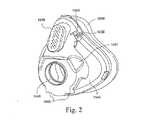
図1、1B〜1Eおよび2〜5に示すように、マスクシステム1010のフレーム1040は、患者の顔に対する機能位置にクッション1060、シュラウド1020およびエルボ1070を維持するように構築される。フレーム1040は、クッション1060(例えばシリコーン製)よりも硬い材料(例えばポリウレタン)から製作(例えば射出成形)されるが、他の材料(例えばポリカーボネート)もおそらくは機能することがある。一実施形態では、フレームの全体的な壁厚が約1〜2mm、例えば1.5mmである。2.1 Frame As shown in FIGS. 1, 1B-1E and 2-5, the
フレーム1040は、患者の鼻および口を受け入れ、患者との空気連通を提供するように適合された呼吸室ないし呼吸空洞を画定する。フレーム1040の一部分すなわち下部は、エルボ1070(例えばスイベルエルボ)を受け取り、または他の方法でエルボ1070と連通するように適合された開口1046を含み、フレーム1040の別の部分すなわち上部は、ガスウォシュアウト(gas washout)用のベント構成1076を含む。さらに、フレーム1040の上部は、シュラウド1020とインタフェースし、または他の方法でシュラウド1020に取外し可能に接続するインタフェース構造1048を含む。
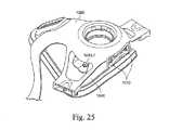
図27〜30は、患者の鼻および/または口との間にシールを形成するように適合された密封部分または密封リングを提供するクッション44を備えたフレーム40を含むマスクシステム10を示す。フレーム40はさらに、エルボ70と連通するように適合された開口46を含む。 FIGS. 27-30 illustrate a
2.2 シュラウド
図1および3〜6に示すように、シュラウド1020はフレーム1040に接続され、マスクシステムにヘッドギアを取り付けるように構築される。一実施形態では、シュラウド1020が、限定はされないがプラスチックまたはナイロン(例えばNylon 12)を含む弾性材料から製作(例えば射出成形)される。しかしながら、シュラウドは、他の適当な材料、例えばポリカーボネート、ポリプロピレン、熱可塑性エラストマー(TPE)、Pocan(登録商標)などから製作することもできる。一実施形態では、シュラウドの全体的な壁厚が約1〜2mm、例えば1.3mmである。2.2 Shroud As shown in FIGS. 1 and 3-6, the
シュラウド1020の上端は、患者の鼻梁領域または鼻の近くに配置されるように適合され、下端は、患者の口または頤(おとがい)の近くに配置されるように適合される。シュラウドの上端は、フレーム1040から突き出すベント構成1076を収容する開口ないしベント受取り穴1021を含み、下端は、エルボ1070およびフレーム1040のエルボ開口(例えば、組み立てられたときにシュラウドがエルボと接触しない)を収容する開口ないしエルボ穴1032を含む。 The upper end of
上端の両側から上ヘッドギアコネクタ1024が延び、下端の両側から下ヘッドギアコネクタ1025が延びる。ヘッドギアコネクタ1024、1025はシュラウドと一体に成形し、または他の方法でシュラウドに取り付けることができる。 An
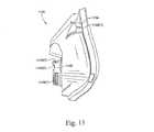
2.2.1 上ヘッドギアコネクタ
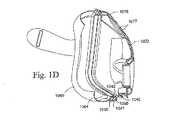
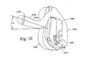
上ヘッドギアコネクタ1024はそれぞれ、細長いアーム1026と、アーム1026の自由端にあって、それぞれのヘッドギアストラップを受け取るように適合されたスロットないし受取り穴1027とを含む。患者の視野を避けるため、すなわちヘッドギアを患者の眼から離して誘導するため、使用時、アーム1026は、患者の顔を巻いて、全体に凹形の角度で、患者の眼よりも下に延びる。例えば、図1Eに示すように、アーム1026はそれぞれ、水平に対して約10〜25°(例えば17°)の角度αで延びることができる。すなわち、アーム1026はそれぞれ、使用時に患者の顔の輪郭に従い、視線を避けるのに適した形態、形状または輪郭に形成される。一実施形態では、アームの形状を、全体に弓形とし、患者の頬を横断する方向に延び、眼を避け、すなわち視野を限定することを避けるように適合させることができる。一実施形態では、アームを、マスクシステムのシュラウドに一体に成形することができる。シュラウド上にアームを成形する1つの可能な利点は、マニュファクチャビリティ(manufacturability)が大幅に増大することであり、さらに、アームが偶発的に破損した場合に、マスクシステム全体を取り替えるのではなく、シュラウドを容易に取り替えることができる。さらに、シュラウド上にアームを成形すると、接続の強度を大幅に高め、アームが破損する実際の可能性を低下させまたは限定することができる。2.2.1 Upper Headgear Connector Each
一実施形態では、患者の顔に対するアームの上下動または屈曲を防ぐため、アーム1026が少なくとも半硬質である(例えば比較的に硬い)。したがって、アーム1026は、安定した構成として有効に機能し、マスクシステムの上端に加わる圧力または力が、マスクシステムの上端と下端の間の釣合いの中心付近にある支点に対して再調整されるという機械的な利点を生み出すリジダイザ(rigidizer)の役目を果たすことができる。この構成をさらに安定にするため、一実施形態では、マスクシステムに対する可能な最も高い点に、アームが取り付けられる。一実施形態では、ピボット回転の支点またはモーメントが、ストラップの上接続点と下接続点の間に配置され、アーム1026の設計、角度、長さおよび/または形状が、この支点を効果的に調整することができる。示した実施形態では、この支点が、マスクシステムのベント構成とエルボの間にあるように示されている。さらに、顔に配置されたとき、マスクシステムは、患者の鼻の底部と唇領域の間の領域の周囲または付近に支点を有することができる。この特徴は、伝統的に必要な額サポートなしで、患者の顔の表面のマスクシステムを効果的に安定化する。 In one embodiment,
マスクシステムの上端から患者の顔の周囲に延びる位置に取り付けられたアーム1026の正味の結果は、使用中に、マスクシステムがより安定し、マスクシステムのx軸1001(図1参照)を軸として受ける正味のねじり力を低減させることである。アーム1026を、マスクシステムの別の適当な位置にしっかりと接続して、同様の結果を生み出すこともできることに留意されたい。 The net result of the
一実施形態では、アーム1026を使用し、患者の頬に接触させることによって、マスクシステムを安定させることができる。使用中に患者の頬に対してアームを支持するために、アームの内面に頬パッドを配置することができる。また、患者の頬に対する追加のパッドの働きをする軟らかい織物スリーブでアーム1026を覆うこともできる。この軟らかい織物スリーブは、アーム1026の一部分を覆う弾力性のある管の形態を有することができる。 In one embodiment, the
2.2.2 下ヘッドギアコネクタ
下ヘッドギアコネクタ1025はそれぞれ、短いアームと、このアームの自由端にあって、それぞれのヘッドギアストラップに結合されたヘッドギアクリップと取外し可能に相互ロック(interlock)するように適合されたクリップレセプタクル1031とを含む。このクリップは、マスクシステムの配置または装着/取外しをより容易にすることを可能にする。一実施形態では、使用中にアームが、マスクシステムに対してy軸1002に沿って横方向に移動することを防ぐために、この短いアームおよびクリップも比較的に硬い。2.2.2 Lower Headgear Connector Each
図27〜30は、クリップレセプタクル31と取外し可能に相互ロックするように適合された例示的なヘッドギアクリップ33を示す。図28に最もよく示されているように、クリップ33はそれぞれ、それぞれのクリップレセプタクル31とスナップばめによって相互ロックするように適合された2つのばねアーム35と、使用時にそれぞれのヘッドギアストラップを受け取るように適合されたスロット37とを含む。 FIGS. 27-30 show an
2.2.3 代替ヘッドギアコネクタ
図27〜30に示すように、アーム26をシュラウドに取外し可能に結合することができ、例えば、アーム26は、シュラウドに配置されたクリップレセプタクルと取外し可能に相互ロックするように適合されたクリップ構造を含む。この構成は、さまざまな型式の上および下ヘッドギアコネクタ、例えば上ヘッドギアコネクタと下ヘッドギアコネクタ両用のアーム、上ヘッドギアコネクタと下ヘッドギアコネクタ両用のクリップ、上ヘッドギアコネクタと下ヘッドギアコネクタで長さが異なるアームなどを、シュラウドとともに使用することを可能にする。2.2.3 Alternative Headgear Connector As shown in FIGS. 27-30, the
しかしながら、シュラウドは、ヘッドギアのヘッドギアストラップを取り付ける別の適当な構成を提供することができる。さらに、シュラウドは、1つまたは複数の追加の構成要素、例えば額サポートを含むことができる。 However, the shroud can provide another suitable configuration for attaching the headgear strap of the headgear. Further, the shroud can include one or more additional components, such as forehead support.
2.2.4 ヘッドギアコネクタの位置
図1〜6の実施形態では、(例えばマスクシステムの頂部および底部における調整を可能にする)より大きな調整性および(例えばアンカー点がマスクシステム全体に分布し、そのため患者の顔の表面でより安定する)安定性を可能にするため、上および下ヘッドギアコネクタ1024、1025が、互いから可能な限り遠いヘッドギア接続点(すなわちフレームの頂部と底部)を提供する。さらに、上ヘッドギアコネクタは、使用中に患者の眼を遮らない限りにおいて、マスクシステムの頂部にできるだけ近い位置に配置される。2.2.4 Headgear Connector Location In the embodiment of FIGS. 1-6, greater adjustability (e.g. allowing adjustments at the top and bottom of the mask system) and (e.g. anchor points are distributed throughout the mask system, so The upper and
2.2.5 分離型シュラウド
図1〜6の実施形態では、シュラウド1020が別個に形成(例えば成形)され、フレーム1040に取り付けられる。このような構成は、シュラウドの成形を容易にし、フレームとシュラウドに対して異なる材料を使用することを可能にし(例えば、フレームは、安定性のため半硬質または硬質とすることができ、ヘッドギアリジダイザを備えるシュラウドは、調整のため柔軟とすることができ)、シュラウドが、エルボをフレームに保持するエルボ/フレーム開口の周囲のエルボ保持フィーチャを隠すことを可能にし(例えば、見た目をよくするため視覚に訴えるシュラウドを提供し)、下クリップレセプタクルのないフレームを可能にし、シュラウドを、さまざまなサイズのフレームとともに使用することを可能にし、マスクシステムができるだけ目障りにならないようにシュラウドを設計し、型式化することを可能にする。この分離型シュラウドはさらに、ヘッドギア、フレーム、クッションおよび/またはエルボを独立に取り替え、洗浄することを可能にする。2.2.5 Separable Shroud In the embodiment of FIGS. 1-6, the
2.2.6 スリーブ
一実施形態では、上および/または下ヘッドギアコネクタに、軟らかい織物スリーブを取り付けることができる。例えば、このスリーブは弾力性を有することができ、このスリーブを、ヘッドギアコネクタのアームの上に滑らせて締りばめを形成するように適合させることができる。一実施形態では、このスリーブが弾力性のある管を形成する。このスリーブにパッドを入れて、使用中のマスクシステムの快適性を増大させることができる。このスリーブは、ヘッドギアコネクタのアームが患者の皮膚と接触する場合に、例えば患者の皮膚を刺激から守るのに特に有用なことがある。2.2.6 Sleeve In one embodiment, a soft textile sleeve can be attached to the upper and / or lower headgear connector. For example, the sleeve can be resilient and the sleeve can be adapted to slide over the arm of the headgear connector to form an interference fit. In one embodiment, this sleeve forms a resilient tube. The sleeve can be padded to increase the comfort of the mask system in use. This sleeve may be particularly useful, for example, to protect the patient's skin from irritation when the arm of the headgear connector contacts the patient's skin.
2.2.7 患者の耳の上側を通って延びるアーム
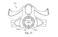
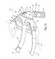
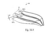
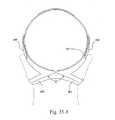
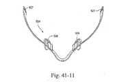
図35-1から35-3および36は、本発明の他の実施形態に基づくマスクシステム210用のシュラウド220を示す。シュラウド220は、フレーム240を保持するように構築された環状保持部分222と、保持部分222の両側の上および下ヘッドギアコネクタ224、225とを含む。示した実施形態では、シュラウド220が、単一片として一体に形成される(例えば図36参照)。2.2.7 Arm Extending Through Upper Side of Patient's Ear FIGS. 35-1 to 35-3 and 36 show a
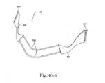
示した実施形態では、上ヘッドギアコネクタ224がそれぞれ、細長いアーム226と、アーム226の自由端にあって、使用時にそれぞれの後部ストラップ298を受け取るように適合されたスロット227とを含む。示されているように、アーム226は、頬に沿い、患者のこめかみのすぐ前方で患者の耳の上側を通って延び、例えば、使用中にストラップが患者の耳をこすり、または刺激することを防ぐために、それぞれの後部ストラップ298を、患者の耳の上側の患者の耳から離隔した位置に保持するのに適した輪郭に形成される。 In the illustrated embodiment, each
さらに、アーム226はそれぞれ、使用時にヘッドギアの上ストラップ292に沿って延び、上ストラップ292と係合するように構築される。ストラップに剛性を追加し、使用中に患者の顔の表面でマスクシステムを安定させるため、示されているように、アーム226はそれぞれ上ストラップ292に固定される。さらに、ストラップ292は、使用時に、患者の顔の表面のアーム226に対するパッドを提供する。一実施形態では、例えば接着または縫合によって、上ストラップ292をアーム226に固定することができる。あるいは、アーム226を、それぞれのストラップ292によって包み込み、またはそれぞれのストラップ292に挿入して、アーム226が実質的に見えないようにすることもできる。 In addition, each
下ヘッドギアコネクタ225はそれぞれ、短いアーム228を含み、その自由端には、使用時にそれぞれの下ストラップ294を受け取るように適合されたスロット229を有する。示されているように、アーム228は、例えば、使用中にストラップが患者の耳をこすり、または刺激することを防ぐために、それぞれの下ストラップ294を、患者の耳の下側の患者の耳から離隔した位置に保持する適当な向きに配置される。 Each
一実施形態では、アームをそれぞれ、マスクシステムの上端に取り付けることができ、アームはそれぞれ、患者の視野または眼よりも下に湾曲し、水平軸から約10度から20度までのある角度で上方へ湾曲する。 In one embodiment, each arm can be attached to the upper end of the mask system, each curved below the patient's field of view or eye and up at an angle from about 10 to 20 degrees from the horizontal axis. Curve to.
代替実施形態では、図36に示すように、下ヘッドギアコネクタ225がそれぞれ、それぞれの下ストラップ294に結合されたヘッドギアクリップ(図示せず)と取外し可能に相互ロックするように適合されたクリップレセプタクル231を含むことができる。一実施形態では、ヘッドギアクリップレセプタクルおよびクリップを、ResMed社のMirage Liberty(商標)マスクのそれらと同様のものとすることができる。例示的なクリップ構成が、参照によってそれぞれその全体が本明細書に組み込まれる米国特許出願公開第2007/0144525号および第2006/0283461号に開示されている。 In an alternative embodiment, as shown in FIG. 36, each of the
2.2.8 上ヘッドギアコネクタのないシュラウド
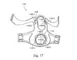
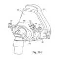
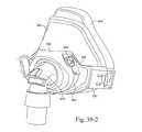
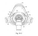
図37-1から37-3は、本発明の他の実施形態に基づくマスクシステム310を示す。示されているとおり、マスクシステム310は、シュラウド320、フレーム340、クッション344およびエルボ370を含む。2.2.8 Shroud Without Upper Headgear Connector FIGS. 37-1 to 37-3 illustrate a
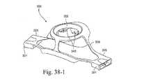
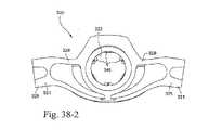
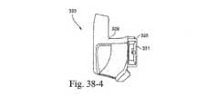
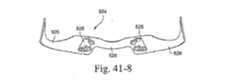
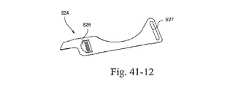
図38-1から38-5に最もよく示されているとおり、シュラウド320は、エルボ370を受け取るように構築された開口322と、その両側のヘッドギアコネクタ325とを含む。示した実施形態では、ヘッドギアコネクタ325がそれぞれ、それぞれの下ヘッドギアストラップに結合されたヘッドギアクリップ(図示せず)と取外し可能に相互ロックするように適合されたクリップレセプタクル331を含む。 As best shown in FIGS. 38-1 to 38-5, the
フレーム340は、シュラウド320、例えばフレーム340のカラーと係合するように適合された開口322から延びるフィンガおよびタブ345に、取外し可能に取り付けられる。
フレーム340は、その上部の両側に、上ヘッドギアコネクタ324を含む。ヘッドギアコネクタ324はそれぞれ、それぞれの上ヘッドギアストラップに結合されたヘッドギアクリップ(図示せず)と取外し可能に相互ロックするように適合されたクリップリテーナ333を含む。
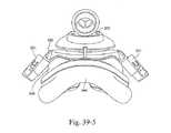
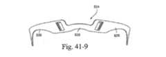
図39-1から39-6は、同様の参照符号によって指示されたマスクシステム310の代替形態を示す。示されているとおり、フレーム340は上ヘッドギアコネクタを持たず、クリップレセプタクル331はそれぞれ、代替構成(例えばクリップ上のスナップばめタブのための穴)を含む。さらに、図39-1から39-6のシュラウド320は、それぞれの補助ポート343を巻くように構築された支持バー329を含み、図37-1から38-5のシュラウド320は、それぞれの補助ポート343の前に延びる支持バー329を含む。 FIGS. 39-1 to 39-6 show alternative forms of the
2.3 ヘッドギア
患者の顔の表面の所望の位置にマスクシステム1010を維持するため、シュラウド1020のヘッドギアコネクタ1024、1025に、ヘッドギアを取外し可能に取り付けることができる。例えば図1Bを参照されたい。2.3 Headgear Headgear can be removably attached to the
図9に示すように、ヘッドギア1090は、一対の上および下ストラップ1092、1094を含み、上ストラップ1092は、それぞれの上ヘッドギアコネクタ1024に取外し可能に取り付けられ、下ストラップ1094は、それぞれの下ヘッドギアコネクタ1025に取外し可能に取り付けられる。それぞれのストラップの自由端は、ストラップの残りの部分と係合してストラップを所定の位置に固定するように構築されたVelcro(登録商標)タブを含むことができる。このようなVelcro(登録商標)による取付けはさらに、ストラップの長さを調整することを可能にする。しかしながら、上および下ヘッドギアストラップは、他の適当な方法、例えば調整可能なラダーロック(ladder-lock)構成などでシュラウドに固定することもできる。 As shown in FIG. 9, the
上ストラップ1092は、患者の頭冠において、使用時に患者の頭の上を通るように適合された(例えばバックルによって互いに接続された)頂部ストラップ1096と、使用時に患者の頭の後ろを通るように適合された後部ストラップ1098とに分かれる。一実施形態では、ヘッドギア1090が、自立するように構築される。 The
図9では、頂部ストラップ1096が、バックルによって互いに接続されるように適合されている。代替実施形態では、図27〜30に示すように、ヘッドギア90が、上および下ストラップ92、94、頂部ストラップ96および後部ストラップ98を含み、頂部ストラップ96を互いに一体とすることができる。 In FIG. 9, the
上ストラップ1092は、調整可能な額サポートがマスクシステムの位置を変更する、すなわちマスクシステムの頂部を患者の鼻梁に近づけまたは患者の鼻梁から遠ざけるのと同様の方法で、マスクの位置を調整するように設計される。 The
額サポートがないため、このヘッドギアは、マスクフレーム1040の頂部および底部にシュラウド1020を介して接続され、眼および耳を避けるため、上ヘッドギアコネクタのアーム1026はある角度で延びる。こうすると、マスクシステムが患者の顔の表面でずり上がる傾向を有するように、ヘッドギアベクトルV1とV2(図1および1B参照)が整列する(すなわち、上ヘッドギアコネクタが上ヘッドギアベクトルを水平から上方へ向け、下ヘッドギアコネクタが下ヘッドギアベクトルを概ね水平に向ける)。患者の頭冠において上ヘッドギアストラップ1092を分割する(すなわち頂部および後部ストラップ1096、1098)ことによって、上ヘッドギアベクトルが、マスクシステムが患者の顔の表面でずり上がることを防ぐように再整列される。 Because there is no forehead support, this headgear is connected to the top and bottom of the
2.3.1 ヘッドギアの調整
図35-1から35-3は、患者の顔の表面の所望の位置にマスクシステムを維持するためにシュラウド220のヘッドギアコネクタ224、225に取り付けられたヘッドギア290を示す。2.3.1 Headgear Adjustment FIGS. 35-1 to 35-3 show the
示した実施形態では、ヘッドギア290が、一対の上ないし頂部ストラップ292、一対の下ないし底部ストラップ294、および一対の後部ストラップ298を含む。使用時、上ストラップ292は、それぞれの上コネクタないしアーム226に固定され、下ストラップ294は、スロット229/クリップ構成231を介してそれぞれの下コネクタに取外し可能に取り付けられ、後部ストラップ298は、スロット227を介してそれぞれの上コネクタに取外し可能に取り付けられる。上ストラップ292は、患者の頭の上を通り、例えばヘッドギアバックルまたは調整可能なラダーロック構成299を介して互いに結合するように適合された上ストラップ部分を含むことができる。示した実施形態では、下ストラップ294と後部ストラップ298とが単一片として形成される。 In the illustrated embodiment, the
このヘッドギア構成は、3つの位置での調整、すなわちヘッドギアバックル299での上ストラップ292の調整、スロット229/クリップ231接続での下ストラップ294の調整、およびスロット227接続での後部ストラップ298の調整を可能にする。 This headgear configuration adjusts in three positions:
示されているように、それぞれのストラップの自由端は、ストラップの残りの部分と係合してストラップを所定の位置に取外し可能に固定するように構築された面ファスナタブ295(例えばVelcro(登録商標))を含むことができる。このような面ファスナ取付けはさらに、ストラップの長さの調整を容易にする。 As shown, the free end of each strap has a hook-and-loop fastener tab 295 (e.g., Velcro®) constructed to engage the rest of the strap to removably secure the strap in place. )). Such hook-and-loop fastener attachment further facilitates adjustment of the strap length.
示した実施形態では、下ストラップ294および後部ストラップ298が結合し、使用時に患者の頭の後ろを通るように適合される(例えば図35-3参照)。示されているように、下ストラップ294は、角度α(例えばResMed社のMirage Libertyマスクの底部ストラップと同様の角度)で結合して、ストラップが患者の首を刺激することを防ぎ、かつ/または使用中に患者の首が動くことによってストラップが移動することを防ぐ。 In the illustrated embodiment, a
一実施形態では、ヘッドギアを、ResMed社のMirage Libertyマスクのヘッドギアと同様のものとすることができるが、頂部ストラップは変更されており、リジダイザシステムが追加されている。頂部ストラップは、側面に沿ってリジダイザが延びるResMed社のSwift型ヘッドギアと同様のものとすることができる。 In one embodiment, the headgear can be similar to the headgear of the ResMed Mirage Liberty mask, but the top strap has been modified and a rigidiser system has been added. The top strap can be similar to ResMed's Swift headgear with a rigidizer extending along the side.
2.3.2 代替ヘッドギア材料
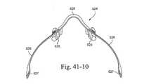
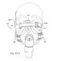
図43-1から43-4は、本発明の他の実施形態に基づくマスク615およびヘッドギア690を含むマスクシステム610を示す。示した実施形態では、ヘッドギア690が、一部のストラップがシリコーンから製作され、一部のストラップがBreath-O-Prene(商標)材料から製作されたストラップの構成を含む。しかしながら、ストラップが完全にシリコーンから製作され、または完全にBreath-O-Prene(商標)から製作されるように、ヘッドギアを製作することもできる。2.3.2 Alternative Headgear Material FIGS. 43-1 to 43-4 illustrate a
示されているように、このヘッドギアの下ストラップ部分692は、Breath-O-Prene(商標)から製作され、頬に沿い、患者の後頭部を巻いて延びる。このヘッドギアの上ストラップ部分694は、シリコーンから製作され、上頬に沿って延び、患者の耳の上側を通るサイドストラップ694(1)と、患者の頭の上を横切って延びる頂部ストラップ694(2)と、患者の頭の後ろを横切って延び、下ストラップ部分692に接続する(図43-4参照)後部ストラップ694(3)と、それぞれのサイドストラップ694(1)から患者の耳の前に延び、下ストラップ部分692に接続する接続部分694(4)とを含む。 As shown, the
ヘッドギアストラップは、適当な任意の方法でマスクに接続することができる。例えば、示した実施形態では、下ストラップ部分692が、ヘッドギアクリップ配置によってマスクに接続され、上ストラップ部分694が、両端にバックル部分を有する細長いバックル695を使用してマスクに接続される。 The headgear strap can be connected to the mask in any suitable manner. For example, in the illustrated embodiment, the
一実施形態では、ヘッドギアによってマスクに加えられる力ベクトルが、(例えば図43-2の矢印によって示されているように)マスクに対しては実質的に垂直、互いに対しては実質的に平行になるように、ヘッドギアストラップが構成される。この構成は、ヘッドギアがマスクを患者の顔に直接に押し付けるため、マスクの密封を強化する。 In one embodiment, the force vector applied to the mask by the headgear is substantially perpendicular to the mask (e.g., as indicated by the arrows in Figure 43-2) and substantially parallel to each other. Thus, a headgear strap is configured. This configuration enhances mask sealing because the headgear presses the mask directly against the patient's face.
3. シール
マスクシステムのシール(すなわちクッション)は、フルフェース型インタフェースからの額サポートの排除に対応するように構築される。3. Seals Mask system seals (ie cushions) are constructed to accommodate the elimination of forehead support from a full face interface.
3.1 クッション
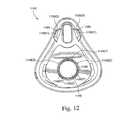
図1〜5および7〜8に示すように、クッション1060は、フレーム1040とインタフェースし、使用時に患者の鼻および口との間にシールを形成するように構築される。示した実施形態では、クッションが、概ね患者の顔の鼻梁、頬および下唇/頤領域に沿って患者の顔と係合するように適合されたフルフェースクッションである。しかしながら、他のクッションインタフェース、例えば鼻インタフェースも可能である。3.1 Cushion As shown in FIGS. 1-5 and 7-8, the
額サポートがないことで一部の安定性が失われることにより生じる動きをより多く吸収するため、クッション1060は、(例えば特に鼻梁領域において)よりしなやかまたは柔軟であるように構築される。 The
クッション1060は、例えばシリコーンなどの軟らかく柔軟な生体適合材料から製作される。示した実施形態では、クッション1060が、図8に示すように膜1064の下にアンダークッション(undercushion)ないし支持壁1062を備える2重壁構成を含む。 The
膜1064は一般に、アンダークッション1062よりも軟らかく、剛性が小さく、使用時に、患者の顔に対するシールを提供する。額サポートがないことによるより小さなマスク安定性を考慮して、患者の顔に対するより幅広い密着範囲およびより良好な一致(conformance)を可能にするため、膜は、比較的に薄くすることができる。アンダークッションは、膜を全般的に支持するように構築され、マスクシステムが取り付けられ、ヘッドギアを使用してしっかりと締められたときに、膜が潰れることを防ぐ。 The
膜1064は全体に凹形であり、呼吸室に向かって内側へ湾曲する。アンダークッション1062も内側へ湾曲するが、膜よりも全体に短く、厚く、硬い。 The
一実施形態では、患者の鼻梁および/または頤領域のアンダークッション1062がより低いか、または全くなく、アンダークッション1062の先端から基部までの高さは約0mmから30mmとすることができる。膜は、所与の断面においてアンダークッション1062よりも全体に長く、約1mmから40mmとすることができる。例えば、図8Bは、クッションの鼻梁および頤領域にアンダークッションがない膜1064を示すために、これらの領域を通る線で切った断面を示す。 In one embodiment, the
一実施形態では、マスクシステムの選択された領域、例えばマスクシステムを患者の顔から押し離す領域にだけ、アンダークッション1062を提供することができる。患者の顔のある所定の領域では、ヘッドギアを締めることによって圧力を加えることを避けることが好ましい。示した実施形態では、患者の鼻梁および頤領域がアンダークッション1062を含まない。これらの領域では、使用中にマスクシステムが加える力ベクトルをより均一に分布させるため、患者の頬を押圧するクッションの側面に沿った部分にだけ、アンダークッションが提供される(例えば図7参照)。一実施形態では、頬領域に沿った部分のアンダークッションの剛性を比較的に高くすることができる。これは、これらの接触点がアンカー点の働きをしている、すなわち、これらの接触点が、効果的なシールを提供する適当な位置にマスクシステムを保持するためである。 In one embodiment, the
患者の鼻梁および頤を避けるこの構成は、患者の顔の敏感な領域または相対的に高い接触圧を受ける突出した領域に加わる圧力または力を低減させることにより、患者が感じるマスクシステムの快適性を増大させることができる。さらに、この構成は、マスクシステムを調整するときに、クッションが患者の鼻梁を挟みつけることを防ぐ。さらに、アンダークッションが存在しないことにより、この実施形態のクッションの鼻梁および頤の領域を、著しく軟らかくすることができる。 This configuration avoiding the patient's nasal bridge and wrinkles reduces the comfort of the mask system felt by the patient by reducing the pressure or force applied to sensitive areas of the patient's face or protruding areas that are subject to relatively high contact pressures. Can be increased. Furthermore, this configuration prevents the cushion from pinching the patient's nasal bridge when adjusting the mask system. In addition, the absence of an undercushion can significantly soften the nose bridge and heel area of the cushion of this embodiment.
一実施形態では、より軽い支持を必要とする前述の顔の所定の領域において可変の軟らかさを生み出すため、アンダークッションが、可変の高さ、剛性および/または厚さを含むことができる。 In one embodiment, the undercushion can include a variable height, stiffness, and / or thickness to create a variable softness in a predetermined area of the face that requires lighter support.
示した実施形態では、クッションが目障りになりにくくなるように、患者の鼻梁および眼窩のより下方で密封するように、クッションを構築することができる。 In the illustrated embodiment, the cushion can be constructed to seal below the patient's nasal bridge and orbit so that the cushion is less obstructive.
一実施形態では、つや出し加工される患者に接する面を除き、クッションを全体につや消し加工することができる。一実施形態では、クッションのつや消しが、顔と膜の間および/または膜とアンダークッションの間の拘束(restriction)を低減させることができる。つや消しは、つや消し加工されていないシリコーンと同じ拘束を引き起こすことなく、膜およびアンダークッションの表面を互いの表面に対して滑らせることを可能にする。この特徴はさらに、膜構成要素とアンダークッション構成要素とのくっつきを防止または限定することができ、さらに、一般に、クッションの全体的な快適性および密封特性を向上させることができる。さらに、クッションのつや消しは製造を容易にし、製造コストの低減につながることがある。クッションは、つや消しシリコーンまたは他の適当な材料から製作することができる。 In one embodiment, the cushion can be entirely frosted except for the surface that contacts the patient to be polished. In one embodiment, matting of the cushion can reduce the restriction between the face and the membrane and / or between the membrane and the undercushion. Matte allows the surfaces of the membrane and undercushion to slide relative to each other without causing the same constraints as non-matte silicone. This feature can further prevent or limit sticking between the membrane component and the undercushion component, and can generally improve the overall comfort and sealing characteristics of the cushion. Furthermore, matting of the cushion can facilitate manufacturing and reduce manufacturing costs. The cushion can be made from matt silicone or other suitable material.
3.2 鼻梁上においてより低いクッション
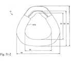
図31-1から31-5は、本発明の一実施形態に基づく(例えばシリコーン製の)クッション44の各種図を示す。示されているとおり、クッション44は、フレームに提供された基部壁44(1)と、基部壁44(1)から遠ざかるように延びるアンダークッション層(UCL)44(2)と、UCL44(2)を実質的に覆い、密封構造を提供するように提供された膜44(3)とを含む。示した実施形態では、使用時にマスクが目障りになりにくくなるように、また「視線」を改善するために、クッション44が、鼻梁上により低く着座するように構築される。3.2 Lower Cushion on Nasal Bridge FIGS. 31-1 to 31-5 show various views of a cushion 44 (eg, made of silicone) according to one embodiment of the present invention. As shown, the
さらに、図31-3および31-5に最もよく示されているように、鼻梁領域のUCL44(2)の設計は、使用時に、鼻梁を横切る安定性が向上するように構築される。図31-1および31-3に示すように、下唇/頤領域にUCLは提供されない。しかしながら、UCLの他の配置、例えば全周にUCLを配置することも可能である。 Further, as best shown in FIGS. 31-3 and 31-5, the design of UCL 44 (2) in the nasal bridge region is constructed to improve stability across the nasal bridge in use. As shown in FIGS. 31-1 and 31-3, no UCL is provided in the lower lip / lid area. However, other arrangements of UCL, for example, UCLs can be arranged all around.
図31-1から31-5に示すクッションの一実施形態では、D1を約15〜20mm、例えば18.2mm、D2を約53〜59mm、例えば55.8mm、D3を約88〜93mm、例えば90mm、D4を約78〜83mm、例えば81.1mm、D5を約58〜63mm、例えば60mm、D6を約95〜100mm、例えば98.1mm、D7を約57〜62mm、例えば59.7mm、D8を約77〜82mm、例えば79mm、D9を約88〜93mm、例えば90.7mm、D10を約30〜35mm、例えば33.1mm、D11を約14〜19mm、例えば16.4mm、D12を約8〜13mm、例えば9.6mm、D13を約0.3〜0.5mm、例えば0.35mm、D14を約0.4〜0.6mm、例えば0.5mm、D15を約0.3〜0.5mm、例えば0.4mmとすることができる。特定の寸法および範囲を示したが、これらの寸法および範囲は単なる例であり、用途に応じた他の寸法および範囲も可能であることを理解されたい。例えば、用途に応じて、これらの例示的な寸法を、10〜20%変更し、あるいはそれよりも大幅にまたはそれよりも小幅に変更することができる。 In one embodiment of the cushion shown in FIGS. 31-1 to 31-5, D1 is about 15-20 mm, for example 18.2 mm, D2 is about 53-59 mm, for example 55.8 mm, D3 is about 88-93 mm, for example 90 mm, D4. About 78-83 mm, e.g. 81.1 mm, D5 about 58-63 mm, e.g. 60 mm, D6 about 95-100 mm, e.g. 98.1 mm, D7 about 57-62 mm e.g. 59.7 mm, D8 about 77-82 mm e.g. 79mm, D9 about 88-93mm, for example 90.7mm, D10 about 30-35mm, for example 33.1mm, D11 about 14-19mm, for example 16.4mm, D12 about 8-13mm, for example 9.6mm, D13 about 0.3 -0.5 mm, for example 0.35 mm, D14 can be about 0.4-0.6 mm, for example 0.5 mm, and D15 can be about 0.3-0.5 mm, for example 0.4 mm. Although specific dimensions and ranges are shown, it is to be understood that these dimensions and ranges are merely examples, and that other dimensions and ranges are possible depending on the application. For example, depending on the application, these exemplary dimensions can be changed by 10-20%, or more or less.
3.3 鼻梁上においてより高いクッション
図35-1および35-2は、概ね患者の顔の鼻梁、頬および下唇/頤領域に沿って患者の顔と係合するように適合されたフルフェースクッション244を示す。この実施形態では、密封性および快適性のため(例えば上述のクッション44に比べて)鼻梁上のクッションがより高く配置されるように、クッション244が構築される。クッション244はさらに、人体計測学(anthropometrics)に関してより好適であることがある。すなわち、このクッションはより多くの人に適合する。3.3 Higher Cushion on the Nasal Bridge FIGS. 35-1 and 35-2 are full face cushions 244 adapted to engage the patient's face generally along the nasal bridge, cheeks and lower lip / lid area of the patient's face. Indicates. In this embodiment, the
一実施形態では、使用中のクッションの柔軟性を高めるため、クッション244が、後述する蛇腹セクション(concertina section)を(例えば鼻梁領域に)含むことができる。 In one embodiment, the
3.4 蛇腹セクション
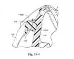
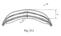
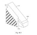
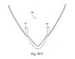
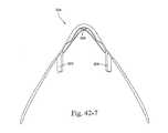
図30および33に最もよく示されているように、クッションおよび/またはフレームの鼻梁領域に、蛇腹セクション50を形成することができる。示されているとおり、蛇腹セクション50は、より高度の柔軟性を提供し、または動きを増大させる1つまたは複数のひだ52を有する蛇腹構造を含む。すなわち、蛇腹セクション50は、使用中に、患者の顔のより敏感な領域であるクッション/フレームの鼻梁領域に、より高いレベルの適合性または柔軟性を提供する。さらに、蛇腹セクション50は、不利な影響をシールに及ぼすことなく動きを増大させる。3.4 Bellows Section As best shown in FIGS. 30 and 33, a
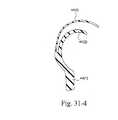
図32-1から32-3は、1つまたは複数のひだ52を有する本発明の一実施形態に基づく蛇腹セクション50(クッション/フレームの残りの部分からは分離されている)の各種図を示す。図32-3に最もよく示されているように、ひだは、蛇腹効果を最適化するため、例えば不利な影響をシールに及ぼすことなく十分な程度の動きを提供するために、互いに対してさまざまな長さ、深さおよび/または輪郭を有することができる。例えば、図32-3に示すように、ひだ52はそれぞれ、第1の側壁52(1)と、隣接する側壁52(1)と相互接続した第2の側壁52(2)とを含む。 FIGS. 32-1 to 32-3 show various views of a bellows section 50 (separated from the rest of the cushion / frame) according to one embodiment of the present invention having one or
示した実施形態では、第1の側壁52(1)および/または第2の側壁52(2)を、患者の顔から離れるにつれて次第に長くすることができる。例えば、患者の顔に隣接する第1の側壁52(1)および/または第2の側壁52(2)、あるいは側壁52(1)と52(2)の組合せは、隣接する側壁52(1)および/または52(2)よりも長い、いくつかのケースでは隣接する側壁52(1)および/または52(2)よりもかなり長い長さを有することができる(例えば、一方の側壁を、もう一方の側壁よりも少なくとも25%大きくすることができ、もう一方の側壁の最大5倍、例えば1倍、2倍、3倍または4倍とすることができる)。 In the illustrated embodiment, the first sidewall 52 (1) and / or the second sidewall 52 (2) can become progressively longer as they move away from the patient's face. For example, the first sidewall 52 (1) and / or the second sidewall 52 (2) adjacent to the patient's face, or the combination of the sidewalls 52 (1) and 52 (2) And / or longer than 52 (2), in some cases can have a length significantly longer than the adjacent side walls 52 (1) and / or 52 (2) (e.g., one side wall Can be at least 25% larger than one side wall and can be up to 5 times, for example, 1 time, 2 times, 3 times or 4 times the other side wall).
所定の順序で動きまたは折り畳まれるように、ひだを構築し、構成することができ、例えば、1つのひだが潰れた後に隣接するひだが潰れる逐次的ないし段階的な方法で折り畳まれるように、ひだを構築することができる。例えば、力が加わると、患者の顔から遠い方のひだよりも前に、患者の顔に近い方のひだが折り畳まれ、または潰れる。さらに、さまざまな程度に折り畳まれまたは潰れるようにひだを構築し、構成することができ、例えば、あるひだが、他のひだよりも多く折り畳まれ、または潰れるようにすることができる。 The folds can be constructed and configured to move or fold in a predetermined order, for example, folds so that they are folded in a sequential or stepwise fashion that collapses one fold and then the adjacent folds. Can be built. For example, when a force is applied, the folds closer to the patient's face fold or collapse before the folds farther from the patient's face. Further, the folds can be constructed and configured to fold or collapse to varying degrees, for example, some folds can be folded or collapsed more than other folds.
図32-1から32-3に示す蛇腹セクションの一実施形態では、D1を約50〜60mm、例えば55.7mm、D2を約5〜15mm、例えば9.7mm、D3を約0.3〜0.5mm、例えば0.4mmとすることができる。特定の寸法および範囲を示したが、これらの寸法および範囲は単なる例であり、用途に応じた他の寸法および範囲も可能であることを理解されたい。例えば、用途に応じて、これらの例示的な寸法を、10〜20%変更し、あるいはそれよりも大幅にまたはそれよりも小幅に変更することができる。 In one embodiment of the bellows section shown in FIGS. 32-1 to 32-3, D1 is about 50-60 mm, such as 55.7 mm, D2 is about 5-15 mm, such as 9.7 mm, D3 is about 0.3-0.5 mm, such as 0.4. mm. Although specific dimensions and ranges are shown, it is to be understood that these dimensions and ranges are merely examples, and that other dimensions and ranges are possible depending on the application. For example, depending on the application, these exemplary dimensions can be changed by 10-20%, or more or less.
例えば患者快適性に従って、蛇腹セクション50を、クッションおよび/またはフレームの他の領域に配置することもできることを理解されたい。例えば、クッションおよび/またはフレームの全周に蛇腹セクション50を配置することができ、あるいは、クッションおよび/またはフレームの選択した領域に蛇腹セクション50を配置することができる。 It should be appreciated that the
さらに、蛇腹セクション50の柔軟性を変更することができ、クッションおよび/またはフレームの異なる領域における蛇腹セクション50の柔軟性を、例えば患者快適性に従って変更することができる。例えば、クッションおよび/またはフレームは、比較的に高い柔軟性を有する蛇腹セクションを鼻梁領域に含み、比較的に低い柔軟性を有する蛇腹セクションを下唇/頤領域に含むことができる。蛇腹セクション50の柔軟性は、ひだ52の数(例えば1〜5個)、ひだ52の壁の長さおよび厚さ、ひだ52の深さなどを変更することによって変化させることができる。 In addition, the flexibility of the
前述のとおり、クッションとフレームを、異なる材料/剛性を有する2つの部分から共成形することができ、または同じ材料から一体に形成することができる。両方の実施形態で、フレームおよび/またはクッションに蛇腹セクションを配置することができる。 As described above, the cushion and frame can be co-molded from two parts having different materials / stiffness or can be integrally formed from the same material. In both embodiments, a bellows section can be placed on the frame and / or cushion.
図27〜30では、クッション44とフレーム40が2つの部分から共成形されており、フレーム40に蛇腹セクション50が配置されている。それぞれの部分の機能を最適化するため、フレーム40とクッション44は異なる剛性を含む。例えば、一方の部分(すなわちクッション44)を、密封効果を最適化するために比較的に軟らかいしなやかな材料から製作し、もう一方の部分(すなわちフレーム40)を、クッションに対する十分な支持を提供し、同時に蛇腹効果を最適化するのに十分な程度の動きを可能にするために、より硬い材料から製作することができる。フレームはクッションよりも硬いが、蛇腹効果を可能にするため、フレームを柔軟な材料から製作することができる。 27 to 30, the
図33では、フレーム40とクッション44が単一片として一体に形成されており、フレーム40に蛇腹セクション50が配置されている。密封効果および蛇腹効果を最適化するため、材料特性および/または寸法を選択的に変更することができる。 In FIG. 33, the
図27〜30と図33の両方の実施形態に関して、蛇腹セクションをあるいは、クッション44に配置し、またはフレーム40とクッション44の両方に配置することもできることを理解されたい。例えば、図34は、クッション44と一体に形成された鼻梁領域の蛇腹セクション50を示す。 With respect to both the embodiments of FIGS. 27-30 and 33, it should be understood that the bellows section could alternatively be located on the
4. エルボ
図3に示すように、エルボ1070(例えばポリカーボネート、ポリプロピレンなどの比較的に硬い材料から製作される)は、第1の端部1074(1)および第2の端部1074(2)を含む。第1の端部1074(1)は、フレーム1040とインタフェースし、または他の方法でフレーム1040に接続するように構築されたインタフェース構造を提供する。第2の端部1074(2)は、空気送達管に接続されるように適合される。4. Elbow As shown in FIG. 3, the elbow 1070 (made from a relatively hard material such as polycarbonate, polypropylene, etc.) has a first end 1074 (1) and a second end 1074 (2). including. The first end 1074 (1) provides an interface structure that is constructed to interface with the
4.1 エルボとフレームの接続
フレーム1040は、患者の顔に対する機能位置にエルボ1070を維持するように構築される。すなわち、フレームは、エルボを担持、支持する表面の役目を果たす。フレームとエルボは、摩擦ばめ、スナップばめ、機械式相互ロックまたは他の適当な取付け機構によって接続することができる、しかしながら、フレームにエルボを取り付ける他の適当な構成も可能である。4.1 Elbow and
示した実施形態では、エルボ1070が、フレーム1040の開口1032と例えばスナップばめによってリリース可能に係合するように適合された一連のタング(tang)1075を含む。タング1075は、エルボを所定の位置に(好ましくは例えば比較的に気密性の接続で)保持し、エルボがフレームに対して回転または旋回することを可能にする。 In the illustrated embodiment, the
すなわち、エルボは、使用中にエルボをフレームに対して例えば360°回転させることができるように、フレームに回転可能に取り付けられる。この構成は、使用中に、例えば患者の好みに応じて、エルボをさまざまな方向に向けることを可能にする。例えば、使用中に空気送達管を患者の頭の下に誘導するため、エルボがマスクから概ね下方へ延びるように、エルボを第1の方向に向けることができる。あるいは、使用中に空気送達管を患者の頭の上に誘導するため、エルボがマスクから上方へ延びるように、エルボを回転させ、第2の方向に向けることもできる。一実施形態では、使用中のフレームとエルボの間のきしみを防ぎ、または少なくとも低減させるため、フレームとエルボを異なる材料から製作することができる。 That is, the elbow is rotatably attached to the frame so that the elbow can be rotated, for example, 360 ° relative to the frame during use. This configuration allows the elbow to be oriented in various directions during use, eg, depending on patient preference. For example, to guide the air delivery tube under the patient's head during use, the elbow can be oriented in a first direction such that the elbow extends generally downward from the mask. Alternatively, the elbow can be rotated and oriented in the second direction so that the elbow extends upward from the mask to guide the air delivery tube over the patient's head during use. In one embodiment, the frame and elbow can be made from different materials to prevent or at least reduce squeezing between the frame and elbow in use.
エルボの第2の端部は、空気送達管に接続されるように適合されたスイベル管継手に提供することができる。例えば、図27〜30は、エルボ70の第2の端部74(2)に提供されたスイベル管継手80を示す。示した実施形態では、スイベル管継手80が、エルボと空気送達管とを相互接続する短い管82(例えば伸縮可能な管)に提供されている。一実施形態では、スイベル管継手80と短い管82を単一片として一体に形成することができる。 The second end of the elbow can be provided on a swivel fitting that is adapted to be connected to an air delivery tube. For example, FIGS. 27-30 show a swivel fitting 80 provided at the second end 74 (2) of the
4.2 AAV
エルボ1070は、窒息防止弁(AAV)を受け取るスロット1081と、(加圧されたガスの存在の有無に応じて)AAVのフラップ部分により選択的に閉じられるポート1079と、AAVを例えばスナップばめによって取り付けるための構造とを含む。4.2 AAV
図27〜30は、エルボ70のポート79を選択的に閉じるフラップ部分86を含む例示的なAAV85を示す。この実施形態では、フラップ部分86に、AAV85をエルボ70に取り付けるためのクリップ部分88が提供される。示した実施形態では、単一片からなる一体の構成要素を形成するため、フラップ部分86とクリップ部分88が互いに共成形される。しかしながら、他の適当な方法、例えば機械式相互ロックで、フラップ部分86とクリップ部分88を互いに固定することもできる。 FIGS. 27-30 illustrate an
一実施形態では、フラップ部分86を、比較的に軟らかいエラストマー材料(例えばシリコーン)から製作し、クリップ部分88を、エルボ70とインタフェースするために、より硬い材料(例えば硬質プラスチック)から製作することができる。 In one embodiment, the
AAV85のクリップ部分88は、例えばスナップばめによってエルボ70と取外し可能に相互ロックするための構造を含む。例えば、クリップ部分88は、エルボに形成されたそれぞれの凹み/突起と相互ロックするように構築されたタブを含むことができる。 The
図35-1および35-2は、(加圧されたガスの存在の有無に応じて)AAV285のフラップ部分286によって選択的に閉じられるポート279を含むエルボ270を示す。また、図37-1から37-3は、ポート379と、AAVを保持するスロット381とを含むエルボ370を示す。 FIGS. 35-1 and 35-2 illustrate an
AAVの代替実施形態が、参照によってその全体が本明細書に組み込まれるPCT出願第PCT/AU2006/000031号に開示されている。 An alternative embodiment of AAV is disclosed in PCT Application No. PCT / AU2006 / 000031, which is incorporated herein by reference in its entirety.
4.3 大径の端部
図27〜30に示すように、エルボ70の第1の端部74(1)は、よりすっきりした/より滑らかなラインの可能性を与え、それによってマスク全体の見栄えをよくし、マスクが目障りになりにくくなるようにするのに貢献する、比較的に大きな直径を有することができる。さらに、この比較的に大径のエルボは、患者の鼻がエルボの空洞内へ突き出す可能性を提供し、それによりマスクが患者の顔により近づく(すなわち目障りになりにくくする)こと、マスクの重心が患者の顔に近づくことによるより小さいモーメント、および/または視線の改善を可能にする。4.3 Large diameter end As shown in Figures 27-30, the first end 74 (1) of the
5. モジュール設計
このマスクシステムは、さまざまな型式および/またはサイズのフレーム(フレームモジュールとも呼ぶ)、シュラウド(シュラウドモジュールとも呼ぶ)、クッション(クッションモジュールとも呼ぶ)および/またはエルボ(エルボモジュールとも呼ぶ)を交換または混合し、互いに適合させて、よりカスタマイズされたマスクシステムを患者に提供することを可能にするモジュール設計を提供する。さらに、このような設計は、例えば治療要件の変化、摩損または破損などに際して、選択したモジュールを容易に取り替えることを可能にする。5. Modular design This mask system can be used in various types and / or sizes of frames (also called frame modules), shrouds (also called shroud modules), cushions (also called cushion modules) and / or elbows (also called elbow modules). A modular design is provided that allows them to be exchanged or mixed and matched to each other to provide a more customized mask system to the patient. In addition, such a design allows for easy replacement of selected modules in the event of changing treatment requirements, wear or breakage, for example.
一実施形態では、マスクシステムが、例えば(例えば患者の好みおよび/または密着性に応じた)異なる型式および/またはサイズのクッションをそれぞれが有するいくつかの異なるクッションを備えることができる。例えば、それぞれのクッションの顔に接しない側が、フレームとインタフェースする共通構成ないし汎用構成を含み、そのクッションの顔に接する側が、異なる型式および/またはサイズを含むことができる。これは、複数のクッションのうちの1つのクッションにフレームを選択的に(例えば取外し可能に)結合することを可能にするモジュール構成を提供する。これらの異なるクッションは例えば、異なるサイズ(例えば小、中および大)のクッションを含み、異なるクッション構造を含むことができる。 In one embodiment, the mask system may comprise a number of different cushions, each having different types and / or sizes of cushions (eg, depending on patient preference and / or adhesion), for example. For example, the side of each cushion that does not contact the face may include a common or general configuration that interfaces with the frame, and the side of the cushion that contacts the face may include different types and / or sizes. This provides a modular configuration that allows the frame to be selectively (eg, detachably) coupled to one of the plurality of cushions. These different cushions include, for example, cushions of different sizes (eg, small, medium and large) and can include different cushion structures.
一実施形態では、マスクシステムが、異なるシュラウド、例えば異なる型式および/またはサイズを有するシュラウド(例えばヘッドギアコネクタの構成/型式が異なるシュラウド、額サポートを有するシュラウド、異なるヘッドギアベクトルを有するシュラウドなど)を備えることができる。 In one embodiment, the mask system comprises different shrouds, e.g., shrouds with different types and / or sizes (e.g., shrouds with different headgear connector configurations / types, shrouds with forehead support, shrouds with different headgear vectors, etc.). be able to.
一実施形態では、マスクシステムが、異なるフレーム、例えば異なる型式および/またはサイズを有するフレーム(例えば異なるベント構成を有するフレーム、小、中および大サイズのフレームなど)を備えることができる。 In one embodiment, the mask system can comprise different frames, such as frames having different types and / or sizes (eg, frames having different vent configurations, small, medium and large sized frames, etc.).
一実施形態では、マスクシステムが、いくつかの異なるエルボ、例えばそれぞれがベント構成を有し、AAV(口鼻マスクの場合)を有し、ならびに/あるいは異なる型式および/またはサイズを有するエルボを備えることができる。図27〜30に示す実施形態では、ベント構成76およびAAV85が、エルボ70に取外し可能に取り付けることができるように構築される。これは、複数のベント構成および/またはAAVのうちの1つにエルボを選択的に、および取外し可能に結合することを可能にするモジュール構成を提供する。これはさらに、ベント構成およびAAVを、例えばこれらが破損した場合に、容易に取り替えることを可能にする。 In one embodiment, the mask system comprises a number of different elbows, e.g., elbows each having a vent configuration, having an AAV (for an oro-nasal mask), and / or having a different type and / or size. be able to. In the embodiment shown in FIGS. 27-30,
5.1 シュラウドとフレームの接続
シュラウドは、フレームの外面に、好ましくは例えばフレーム上への一致した締りばめによって取り付けられる。5.1 Connecting the shroud to the frame The shroud is attached to the outer surface of the frame, preferably by a matched interference fit onto the frame, for example.
5.1.1 上保持機構
図1〜5に示す実施形態では、フレームの上端に位置する上保持機構ないしインタフェース構造1048によって、シュラウド1020がフレーム1040に接続される。5.1.1 Upper Retention Mechanism In the embodiment shown in FIGS. 1-5, the
図2から5に示すように、上保持機構1048は、フレーム1040上にシュラウド1020を固定し、特にヘッドギアの力による意図しない分解を防ぐように構築された2つのテーパロック(taper lock)の形態を有する。この実施形態では、フレームの両側が、シュラウド1020の裏面の(その長さに沿ってテーパを有する)それぞれのタング突起を受け取るように適合された雌型スロット1055を含む。このテーパの付いた突起は、例えば摩擦ばめによって、それぞれの雌型スロットと係合する。 As shown in FIGS. 2 to 5, the
図10から19-4は、テーパロックの一実施形態をより明瞭に示す、マスクシステム1110の他の実施形態を示す。図10から17は、マスクシステム1110のフレーム1140、シュラウド1120およびエルボ1170の各種図を示す。 FIGS. 10 through 19-4 illustrate another embodiment of a
図11から13に最もよく示されているように、フレーム1140の上端の両側は、第1の雌型スロット1155(1)を提供するプラットホーム1154を含む。さらに、プラットホーム1154とフレーム1140の外面との間の空間が、第2の雌型スロット1155(2)を画定する。図17に最もよく示されているように、シュラウド1120の上端の両側は、シュラウド1120の裏面にタング突起1156を含む。タング突起1156は、第1のタング1156(1)と、第1のタング1156(1)に対して概ね直角に延びる第2のタング1156(2)とを含む。図18-1および18-2に示すように、タングはそれぞれ、その長さに沿ってテーパを有する。すなわちその自由端に向かってより薄くなる。 As best shown in FIGS. 11-13, both sides of the upper end of the
図18-1および18-2ならびに19-1から19-4は、シュラウド1120のフレーム1140への取付けを順番に示す。示されているとおり、それぞれのタング突起1156のタング1156(1)、1156(2)は、それぞれのスロット1155(1)、1155(2)と、例えば摩擦ばめによって係合するように構築される。図19-1から19-4に最もよく示されているように、スロット1155(2)はそれぞれ、タング1156(2)をスロット1155(2)内へ誘導し、組立てを助けるためにその長さに沿って湾曲する(すなわち垂直および水平方向に広がる)リードイン(lead-in)ないし案内1157を含む。図18-2および19-4は、それぞれのスロット1155(1)、1155(2)に完全に挿入されたときのタング1156(1)、1156(2)を示す。 FIGS. 18-1 and 18-2 and 19-1 to 19-4 show the mounting of the
代替実施形態では、図20に示すように、上保持機構がクリップ型構成を含むことができる。示されているように、フレーム1240の上端の両側が、ショルダ1255(1)およびテーパの付いた突起1255(2)を提供する。シュラウド1220の上端の両側は、シュラウド1220の裏面に、第1のタング1256(1)および第2のタング1256(2)を含む。使用時、第1のタング1256(1)はそれぞれ、それぞれのショルダ1255(1)と係合し、第2のタング1256(2)は、テーパの付いた突起1255(2)と、例えばスナップばめによって係合し、またはクリップ留めされる。 In an alternative embodiment, the upper retention mechanism can include a clip-type configuration, as shown in FIG. As shown, both sides of the upper end of the
5.1.2 下保持機構
一実施形態では、フレームおよびシュラウドの下端に位置する下保持機構によっても、シュラウドをフレームに接続することができる。例えば、フレームの開口と相互ロックし、または他の方法で係合するように構築された保持機構を、シュラウドの開口に提供することができる。5.1.2 Lower Retention Mechanism In one embodiment, the shroud can also be connected to the frame by a lower retention mechanism located at the lower ends of the frame and shroud. For example, a retention mechanism constructed to interlock or otherwise engage with the opening in the frame can be provided to the opening in the shroud.
例えば、図14、15、17および21に示すように、シュラウド1120の開口1132は、フレームの開口1146を取り囲むカラー1149と、スナップばめによって係合するように適合された構造を含むことができる。示されているように、シュラウド1120は、開口1132から延びるスナップフィンガ1145(1)(例えば3つのスナップフィンガ)およびサンドイッチタブ1145(2)(例えば3つのサンドイッチタブ)を含む。スナップフィンガとサンドイッチタブは、開口の周囲に間隔を置いて交互に配置される。 For example, as shown in FIGS. 14, 15, 17 and 21, the
使用時、スナップフィンガ1145(1)は(例えば0.5mm)弾性偏向し、カラー1149に形成されたそれぞれの部分環状突起1149(1)と係合して(例えば図22および23参照)、例えば組立ておよび分解を容易にするフレーム1140に対するシュラウド1120の(例えば許容応力での)最初の保持を提供する。さらに、スナップフィンガ1145(1)がそれぞれの突起1149(1)と係合すると、サンドイッチタブ1145(2)が、カラー1149の端に形成されたそれぞれの凹み1149(2)に受け取られる(例えば図22および23参照)。エルボ1170をフレーム1140と係合させると(例えば図23参照)、エルボ1170の環状突起1171がサンドイッチタブ1145(2)の反対側の面に配置され、その結果、サンドイッチタブ1145(2)はカラー1149とエルボ1170の間に挟まれる。このように、サンドイッチタブはエルボの保持力を利用して、使用中、シュラウドをフレーム上に保持する。エルボ1170は、フレーム1140の縁の下に延びてエルボをフレームに保持するように適合された遠位側ショルダ1173を有する。スナップフィンガ1145(1)は、エルボとは無関係に、シュラウドがフレームに接続することを可能にする。 In use, the snap finger 1145 (1) is elastically deflected (e.g. 0.5mm) and engages with each partial annular projection 1149 (1) formed on the collar 1149 (e.g. see FIGS. 22 and 23), e.g. assembled. And provides initial retention of shroud 1120 (eg, at an acceptable stress) relative to frame 1140, which facilitates disassembly. Further, when the snap fingers 1145 (1) engage the respective protrusions 1149 (1), sandwich tabs 1145 (2) are received in the respective recesses 1149 (2) formed at the end of the collar 1149 (e.g., FIG. 22 and 23). When the
代替実施形態では、図24に示すように、シュラウドの下部を、カラーの下方の単一の点にクリップ留めされるように構築することができる。示されているように、シュラウド1320の下端は、フレーム1340のカラー1349の下方に間隔を置いて配置された突起1349(1)と例えばスナップばめによって係合し、またはクリップ留めされるスナップフィンガ1345を含む。この実施形態では、突起1349(1)が、補助ポートを囲うカバーから延びる。この構成は、フレーム上のカラーの成形を容易にすることがあり、例えば、均一な厚さのカラーは成形の歪みを防ぐ。さらに、カラーから突起1149(1)/凹み1449(2)を除去することによって、漏れの危険が低減することがある。 In an alternative embodiment, as shown in FIG. 24, the lower portion of the shroud can be constructed to be clipped to a single point below the collar. As shown, the lower end of the
5.1.3 指グリップ
一実施形態では、フレーム1040の外面が、シュラウド1020の下で露出するように配置された指グリップないし凹部1097を含むことができる。指グリップは、フレームおよび/またはシュラウドを把持する改良された能力を患者に与えるように適合され、この能力は、フレームからシュラウドを分離するときに特に有用である。5.1.3 Finger Grip In one embodiment, the outer surface of the
5.1.4 代替インタフェース構造
代替実施形態では、図27〜30に示すように、シュラウド20が、フレーム40およびエルボ70を保持するように構築された環状または部分環状保持部分22を提供する開口構造を含む。示されているように、環状保持部分22は、フレーム40の外周に沿ったインタフェース構造48(例えば図28参照)とインタフェースし、または他の方法でインタフェース構造48に取外し可能に接続するように適合されたインタフェース構造23を、内縁に沿って含む。示した実施形態では、インタフェース構造23が、フレーム40の両側に配置されたそれぞれのロック構造48(1)と相互ロックするように適合された対向するフランジ23(1)の形態を有する。しかしながら、フレーム40をシュラウド20に取り付ける他の適当な構成、例えば摩擦ばめ、スナップばめ、機械式相互ロックまたは他の適当な取付け機構も可能である。5.1.4 Alternative Interface Structure In an alternative embodiment, as shown in FIGS. 27-30, the
例えば、シュラウド20、例えばピボット回転するように取り付けられたシュラウド20に対するさまざまな角度位置に、フレーム40をロックすることができるある方法で、フレーム40をシュラウド20に結合することもできる。 For example, the
5.1.5 代替上ヘッドギアコネクタ
図40-1から40-7は、本発明の他の実施形態に基づくフレームおよびクリップ留め上ヘッドギアコネクタないしリジダイザを示す。5.1.5 Alternative Upper Headgear Connector FIGS. 40-1 to 40-7 illustrate a frame and clipped upper headgear connector or rigidizer according to another embodiment of the present invention.
フレーム442は、シュラウドおよび/またはエルボと係合するように適合された開口449を含む。開口449の周囲および下には、ガスウォシュアウト用のu字形スロット402があり、開口449の両側には補助ポート443がある。
この実施形態では、フレーム442の上部の両側がそれぞれ保持部材433を含み、フレーム442の上部の中間部分が、上ヘッドギアコネクタないしリジダイザ424を保持するように構築され、構成された保持溝435を含む。 In this embodiment, both sides of the upper portion of the
図40-6および40-7に最もよく示されているとおり、上ヘッドギアコネクタ424は、一対のワイヤ部材428によって結合された一対の細長いアームないしリジダイザ426を含む。リジダイザ426はそれぞれその自由端に、使用時にそれぞれのヘッドギアストラップを受け取るように適合されたスロット427を含む。 As best shown in FIGS. 40-6 and 40-7, the
上ヘッドギアコネクタ424は、使用時にフレーム442上にクリップ留めされるように適合される(例えば図40-1および40-2参照)。具体的には、ワイヤ部材428の中間部分が、フレーム442のそれぞれの溝435の中に受け取られ、ワイヤ部材428の端部が、それぞれの保持部材433を貫いて延び、リジダイザ426が、それぞれの保持部材433と相互ロックするショルダを提供する。それぞれのワイヤを受け取るように適合された溝433(1)を示すため、図40-4および40-5に保持部材433の上部を示す。示されているように、溝433(1)の端は、テーパの付いた側壁433(2)を含み、保持部材433と相互ロック係合するようにリジダイザ426を配置するため、背面433(3)に向かって落ち込む。
図41-1から41-12は、本発明の他の実施形態に基づくフレームの上部およびクリップ留め上ヘッドギアコネクタないしリジダイザを示す。 FIGS. 41-1 to 41-12 show the top of the frame and the clip-on headgear connector or rigidizer according to another embodiment of the present invention.
示されているように、フレーム542の上部は、上ヘッドギアコネクタないしリジダイザ524を保持するように構築され、構成された、フレーム542の両側の保持部材533と、フレーム542の中間部分に沿った保持溝535とを含む。 As shown, the upper portion of the
図41-5および41-12に最もよく示されているとおり、上ヘッドギアコネクタ524は、接続部分528によって結合された一対の細長いアームないしリジダイザ526を含む。リジダイザ526はそれぞれその自由端に、使用時にそれぞれのヘッドギアストラップを受け取るように適合されたスロット527を含む。上ヘッドギアコネクタ524はさらに、接続部分528の両側にクリップ構造525を含む。 As best shown in FIGS. 41-5 and 41-12, the
上ヘッドギアコネクタ524は、使用時にフレーム542上にクリップ留めされるように適合される(例えば図41-1および41-2参照)。具体的には、接続部分528が、フレーム542の溝535の中に受け取られ、クリップ構造525が、それぞれの保持部材533とリリース可能に相互ロックする。図41-3および41-4に最もよく示されているとおり、保持部材533はそれぞれクロスバーを提供し、クリップ構造525はそれぞれ、クロスバーを貫通して弾性偏向し、クロスバーとリリース可能に相互ロックするショルダを提供するように適合されたv字形の外形を提供する。 The
図42-1から42-7は、上ヘッドギアコネクタをフレームと係合させる代替実施形態を示す。示されているとおり、保持部材533はそれぞれ開端型のクロスバーを提供し、クリップ構造525はそれぞれ細長いアームを提供する。この実施形態では、クリップ構造525が、クロスバーを貫通して延び、クロスバーと例えば摩擦ばめによってリリース可能に係合することを可能にするため、クロスバーが、弾性偏向するように構築される。さらに、図42-1から42-7の上ヘッドギアコネクタ524は、フレーム542に形成されたタブ549(図42-1および42-2参照)と相互ロックするように適合されたc字形クリップ構造529を含む。 Figures 42-1 to 42-7 show an alternative embodiment in which the upper headgear connector is engaged with the frame. As shown, each retaining
5.1.6 グロメット取付け
図44および45は、グロメット(grommet)によってシュラウドがフレームに取り付けられる代替マスク構成を示す。5.1.6 Grommet Installation FIGS. 44 and 45 show an alternative mask configuration in which the shroud is attached to the frame by a grommet.
例えば、図44に示すように、フレーム740が、(例えばゴム製の)グロメット745を含み、シュラウド720が、グロメット745を受け取ってシュラウド720をフレーム740に固定するように適合された開口725を含む。示されているように、シュラウド720は、細長い上および下アーム724、726を含み、アーム724、726はそれぞれその自由端に、使用時にそれぞれのヘッドギアストラップを受け取るように適合されたスロット727を含む。 For example, as shown in FIG. 44, the
図45は、単一のアームを含む代替シュラウド820を示し、この単一のアームはその両端に、使用時にそれぞれのヘッドギアストラップを受け取るように適合されたスロット827を含む。シュラウド820はさらに、フレーム740のグロメット745を受け取るように適合された細長い内側スロット825を提供する。単一の固定位置を提供するシュラウド720とは対照的に、細長いスロット825は、スロット825の全長に沿った複数の位置のうちの1つの位置にグロメット745を固定することを可能にする。一実施形態では、フレーム740に対する無数の位置を可能にするため、シュラウド820をグロメット745に対してスライド可能とすることができる。 FIG. 45 shows an
それぞれの実施形態では、(例えばゴム製の)グロメット745がシュラウドを適当な位置に固定するが、グロメットの固有の柔軟性は、フレームからシュラウドを分離し、例えば玉継手またはジンバルのように、これらの2つの構成要素間のある移動範囲を可能にする柔軟な接続を提供する。このような構成は、患者の顔に対するマスクの密着および密封に役立つ。すなわち、この柔軟な接続は、マスクが選択的に調整され、かつ/または患者の顔に自動的に密着することを可能にする。 In each embodiment, a grommet 745 (e.g., made of rubber) secures the shroud in place, but the inherent flexibility of the grommet separates the shroud from the frame, such as a ball joint or gimbal. Provides a flexible connection that allows some range of movement between the two components. Such a configuration helps to seal and seal the mask to the patient's face. That is, this flexible connection allows the mask to be selectively adjusted and / or automatically adhered to the patient's face.
5.2 クッションとフレームの接続
図1〜8では、クッション1060の顔に接しない側がフレーム1040に、溝形(tongue and groove)関係で接続される。クッション1060のトング(tongue)1066(図1C、1Dおよび8参照)が、フレーム1040の周囲に沿って形成された溝1041(図1Cおよび1D参照)に挿入される。この溝形関係はさらに、フレームの溝の中のアンダーカットされたビード1042(図1Cおよび1D参照)と相互ロックして、クッションをフレームに対して固定可能に保持するように適合されたロックリップないし密封リップ1068(図1C、1Dおよび8参照)をクッション上に含むことができる。5.2 Connection of Cushion and Frame In FIGS. 1-8, the side of the
示した実施形態では、クッション1060がさらに、クッションとフレーム1040の適正な位置合せの助けとなるようにクッションの周囲に配置された1つまたは複数の位置決めフィーチャを含む。図7に示すように、クッション1060は、フレームの相補フィーチャと例えば相互ロック関係で係合するように適合された切欠きおよび/または突起(例えば2つの切欠き1067および1つの突起1069)を含む。 In the illustrated embodiment, the
5.2.1 フレームとクッションの共成形
一実施形態では、図27〜30に示すように、フレーム40とクッション44を互いに共成形して、単一片からなる一体の構成要素を形成することができる。例えば、シュラウド20とインタフェースするように適合された第1の材料からフレーム40を成形し、患者の顔とインタフェースするように適合された第2の材料のクッション44を、フレーム40上に共成形することができる。5.2.1 Co-molding of frame and cushion In one embodiment, as shown in FIGS. 27-30, the
このような実施形態では、密封のため、クッション44を、比較的に軟らかいエラストマー材料(例えばシリコーン)から製作し、シュラウドとインタフェースするため、フレーム40を、クッション44よりも硬い材料(例えばポリカーボネート、ポリプロピレン)から製作することができる。 In such embodiments, for sealing, the
フレーム40とクッション44の共成形は化学結合を提供し、機械式相互ロックを形成する必要は必ずしもない。その結果、この接続は亀裂を含まず、気密シールおよび滑らかな境界面を含む。さらに、共成形されたこのような接続は、成形材料が、フレーム40とクッション44の境界面の隙間を埋める十分な柔軟性を有するため、許容差を緩和する。さらに、共成形されたフレーム/クッションは、部品数を減らし(コストを低減させ)、シュラウド20との組立て/分解を容易にする。 The co-molding of
代替実施形態では、図33に示すように、フレーム40とクッション44を、例えばシリコーン材料から、単一片として一体に形成することができる。すなわち、フレーム40は、上述のフレームと同じ形状および構造を有するが、同じ材料、例えばシリコーンから成形することができる。 In an alternative embodiment, as shown in FIG. 33, the
一実施形態では、一体に形成されたフレーム40/クッション44を、例えばポリカーボネートまたはポリプロピレンから製作されたシュラウド20に共成形することができる。例えば、比較的に硬い材料(例えばポリカーボネートまたはポリプロピレン)からシュラウド20を製作し、比較的に軟らかいエラストマー材料(例えばシリコーン)のフレーム40/クッション44を、シュラウド20上に共成形することができる。 In one embodiment, the integrally formed
5.3 ベント構成
図1、1B、1C、1Dおよび2〜5では、フレームにベント構成1076が提供され、ベント構成1076は、患者が寝ているときに、排出された空気が、患者および好ましくは患者と一緒に寝ている人から遠ざかるように誘導されることが保証されるように、フレームの外面に対してある角度(例えば45度)で配置された複数の穴1077(例えば5〜100個、例えば20〜50個または約35個)を含む。図1Cおよび1Dに示すように、穴1077はそれぞれ、その長さに沿って輪郭またはテーパを含むことができる。しかしながら、ベント構成は、例えば穴の数や、穴の構成、フレーム上の位置が異なったり、ベントがシュラウドとの相互ロック構造の一部を構成したりするなど、他の適当な構成を含むこともできることを理解されたい。5.3 Vent Configuration In Figures 1, 1B, 1C, 1D and 2-5, the frame is provided with a
図35-1は、フレーム240に提供されたガスウォシュアウト用のベント構成276を示す。示した実施形態では、ベント構成276が、フレーム240の出口開口内に取外し可能に支持されるように適合されたベントインサート(例えばエラストマーベントインサート)の形態を有する。このベントインサートは、参照によってそれぞれその全体が本明細書に組み込まれる米国特許第6,561,190号、第6,561,191号および第7,207,335号に記載されているものと同様のものとすることができる。しかしながら、このベント構成は、(例えば本体にあけられたベント穴など)他の適当な形態を有することができることを理解されたい。 FIG. 35-1 shows a
図37-3、39-2および39-4は、ガスウォシュアウト用のu字形栓型ベント305を受け取るu字形スロット302を含むフレーム340を示す。示されているように、栓型ベント305は、エルボ370のためのフレーム340の開口の周囲および下に位置する。栓型ベント305は、その両側面に複数のトラックないし溝307を含む。使用時、溝付き栓型ベント305は、スロット302との間に、排出された空気が、スロットの壁と栓型ベント305上の溝307との間から外へ出ることができるようなシールを形成する。一実施形態では、ポートキャップ347を、栓型ベント305と一体化し、または栓型ベント305に組み込む(例えば単一片として一体に形成する)ことができる。このような栓型ベント構成のさらなる詳細が、参照によってその全体が本明細書に組み込まれる2008年8月22日に出願された米国特許出願第12/230,120号において提供されている。図39-2から39-6は、u字形スロット302およびフレーム340の両側の補助ポート343をより明瞭に示すために、溝付き栓型ベント305が取り外されたフレーム340を示す。 FIGS. 37-3, 39-2, and 39-4 show a
エルボにベント構成を提供することもできることに留意されたい。例えば、図27〜30に示すように、ベント構成76は、エルボ70の出口開口の中で取外し可能に支持されるように適合されたベントインサートの形態を有する。一実施形態では、ベント構成76が、出口開口の中で支持されるように適合されたベースと、ベースに提供され、ベント流を拡散させるように構築された1つまたは複数の格子構成要素ないし媒体(例えばフィルタ、膜または他の多孔質材料)と、格子構成要素/媒体をベース内に維持するカバーとを含む。図27〜30では、ベント構成76のカバー77だけが見えている。 Note that the elbow can also be provided with a vent configuration. For example, as shown in FIGS. 27-30, the
このようなベント構成の例示的な実施形態が、参照によってその全体が本明細書に組み込まれる2008年8月22日に出願された米国特許出願第12/230,120号に開示されている。 An exemplary embodiment of such a vent configuration is disclosed in US patent application Ser. No. 12 / 230,120 filed Aug. 22, 2008, which is incorporated herein by reference in its entirety.
しかしながら、ベント構成は、他の適当な構成、例えば1つまたは複数のベント穴を有するベントインサートを含むことができることを理解されたい。 However, it should be understood that the vent configuration may include other suitable configurations, such as a vent insert having one or more vent holes.
エルボは、ベントインサートに代わる代替ベント構成を提供することもできる。例えば、図30に破線で示されているように、エルボ70の第1の端部74(1)は、(例えばインタフェース構造75に沿って)ガスウォシュアウト用の1つまたは複数のベント穴276を含むことができる。この1つまたは複数の穴276は、エルボの軟らかい部分(例えば後述するシリコーンシール)および/または硬い部分(例えばポリカーボネート、ポリプロピレン)に形成することができる。穴276は、第1の端部74(1)の全周に沿って、あるいは第1の端部74(1)の1つまたは複数の部分に沿って分布することができる。エルボの全周に沿ってベント穴を配置することが、使用中にベント流を分散させるのに役立つことがあることに留意されたい。しかしながら、第1の端部74(1)および/またはエルボの他の部分に沿った他の適当な穴の配置、穴の数および/または穴の形状も可能である。 The elbow can also provide an alternative vent configuration to replace the vent insert. For example, as indicated by the dashed line in FIG. 30, the first end 74 (1) of the
5.4 ポート
図1〜5では、フレーム1040の基部が、使用中に、酸素または他の呼吸に適したガスを患者の鼻孔の近くに送達することができるように、あるいは圧力監視機器を取り付けることができるように配置された2つのポート1043を含む。ポート1043を使用して、圧力センサ、流量センサなどの追加の医療機器を取り付けることもできる。これらのポートは、ポートキャップによって選択的に閉じまたは密封することができる。5.4 Ports In Figures 1-5, the base of the
代替実施形態では、図25および26に示すように、フレーム1040が、例えばポート1043に加えて、またはポート1043の代わりに、サイドポート1043.1を含むことができる。 In an alternative embodiment, as shown in FIGS. 25 and 26, a
図35-1および35-2は、例えば補充用酸素、測定装置などのための補助ポートないしスピゴット(spigot)243をその上部に含むフレーム240を示す。 FIGS. 35-1 and 35-2 show a
図37-1から37-3および39-1から39-6では、フレーム340が、例えば補充用酸素、測定装置などのための補助ポートないしスピゴット343をその両側に含む。それぞれのポート343を密封するためにポートキャップ347が提供される。 In FIGS. 37-1 to 37-3 and 39-1 to 39-6, the
6. 境界面シール
一実施形態では、エルボとシュラウドの境界面、フレームとシュラウドの境界面および/またはエルボとフレームの境界面に、シールを提供することができる。例えば、これらのモジュールとは別個にシール(例えばリング形エラストマーシール)を形成し、(例えばモジュール間に挟み込む、接着するなどによって)境界面に取り付けることができる。あるいは、これらのモジュールのうちの1つまたは複数のモジュールにシールを共成形することもできる。一実施形態では、シリコーンのリップシールをフレームに取り付けて、エルボに対して密封し、それにより漏れを低減させることができる。6. Interface Seals In one embodiment, a seal may be provided at the elbow-shroud interface, the frame-shroud interface, and / or the elbow-frame interface. For example, a seal (eg, a ring-shaped elastomer seal) can be formed separately from these modules and attached to the interface (eg, sandwiched between, glued, etc.). Alternatively, the seal can be co-molded on one or more of these modules. In one embodiment, a silicone lip seal can be attached to the frame and sealed against the elbow, thereby reducing leakage.
他の実施形態では、図27〜30に示すように、エルボ70のインタフェース構造75を、エルボ70とシュラウド20の境界面にシールを提供するように構築された比較的に軟らかい密封材料(例えばシリコーン。これをエルボのより硬い材料に共成形することができる)から製作することができる。さらに、この比較的に軟らかいインタフェース構造75(例えばシリコーン)は、締りばめ型のはめあいを可能にすることがある、比較的に硬いシュラウド20(例えばポリカーボネート、ポリプロピレン)への「軟らかい」取付けを提供する。前述のとおり、このより軟らかいインタフェース構造および/またはより硬いエルボには、1つまたは複数のベント穴を形成することができる。 In other embodiments, as shown in FIGS. 27-30, the
現時点の最も実際的で好ましい実施形態であると考えられるものに関して本発明を説明したが、本発明は、開示された実施形態に限定されず、反対に、本発明の趣旨および範囲に含まれるさまざまな変更および等価の構成をカバーすることが意図されていることを理解されたい。上記のさまざまな実施形態は、他の実施形態と関連させて実現することもでき、例えば、ある1つの実施形態の諸態様を、別の実施形態の諸態様と組み合わせて、これらとは別の実施形態を実現することもできる。また、任意の所与のアセンブリの独立したそれぞれのフィーチャまたは構成要素が追加の実施形態を構成することがある。さらに、任意の所与のアセンブリの個々のそれぞれの構成要素、任意の所与のアセンブリの個々の構成要素の1つまたは複数の部分、および1つまたは複数の実施形態からの構成要素のさまざまな組合せは、1つまたは複数の装飾的設計フィーチャを含むことがある。加えて、本発明は特に、OSAに苦しんでいる患者に対して適用できるが、他の疾患(例えばうっ血性心不全、糖尿病、病的肥満、脳卒中、肥満手術など)に罹っている患者も、上記の教示から利益を得ることができることを理解されたい。さらに、上記の教示は、非医療用途において、患者および非患者に等しく適用することができる。 Although the present invention has been described with respect to what is considered to be the most practical and preferred embodiments at the present time, the invention is not limited to the disclosed embodiments, but on the contrary, various within the spirit and scope of the invention. It should be understood that such changes and equivalent configurations are intended to be covered. The various embodiments described above can also be implemented in connection with other embodiments, for example, aspects of one embodiment combined with aspects of another embodiment, Embodiments can also be realized. Also, each independent feature or component of any given assembly may constitute an additional embodiment. Further, individual respective components of any given assembly, one or more portions of individual components of any given assembly, and a variety of components from one or more embodiments A combination may include one or more decorative design features. In addition, the present invention is particularly applicable to patients suffering from OSA, although patients suffering from other diseases such as congestive heart failure, diabetes, morbid obesity, stroke, bariatric surgery etc. It should be understood that benefits can be obtained from the teachings of Furthermore, the above teachings are equally applicable to patients and non-patients in non-medical applications.
10 マスクシステム
20 シュラウド
22 シュラウドの環状保持部分
26 アーム
31 クリップレセプタクル
33 ヘッドギアクリップ
40 フレーム
44 クッション
50 蛇腹セクション
70 エルボ
74(1) エルボの第1の端部
74(2) エルボの第2の端部
75 エルボのインタフェース構造
76 ベント構成
77 ベント構成のカバー
79 エルボのポート
80 スイベル管継手
82 短い管
85 窒息防止弁(AAV)
86 AAVのフラップ部分
88 AAVのクリップ部分
90 ヘッドギア
92 上ストラップ
94 下ストラップ
276 ベント穴10 Mask system
20 Shroud
22 Shroud ring retainer
26 Arm
31 Clip receptacle
33 Headgear clip
40 frames
44 Cushion
50 bellows section
70 Elbow
74 (1) Elbow first end
74 (2) Elbow second end
75 Elbow interface structure
76 Vent configuration
77 Vent configuration cover
79 Elbow Port
80 Swivel fitting
82 short tube
85 Suffocation prevention valve (AAV)
86 AAV flap
88 AAV clip
90 headgear
92 Upper strap
94 Lower strap
276 Vent hole
Claims (43)
Translated fromJapanese(i)ヘッドギアと;
(ii)エルボと;
(iii)クッションモジュールであって、
使用時に患者の顔との間にシールを形成するよう比較的軟質なエラストマー材料から構成されるクッションと、
呼吸室を画定する、比較的硬い材料から構成されるフレームと、を備え、
前記フレームは、複数の穴を有する突出ベント構成を含み、
前記クッションと前記フレームとは、単一の一体構成要素として構成されている、
クッションモジュールと;
(iv)一対の上ヘッドギアコネクタと一対の下ヘッドギアコネクタとを含むシュラウドであって、前記上ヘッドギアコネクタと前記下ヘッドギアコネクタとが、前記ヘッドギアに接続されるよう構成されている、シュラウドと;
を備え、
前記シュラウドは、前記突出ベント構成を収容するための第1の開口を含み、さらに前記シュラウドは、前記エルボを収容するための第2の開口を含み、かつ、さらに前記シュラウドは、前記クッションモジュールを交換できるように前記フレームを取外し可能に保持するよう構成された保持部分を含むことを特徴とするマスクシステム。A mask system,
(I) headgear;
(Ii) with an elbow;
(Iii) a cushion module,
A cushion composed of a relatively soft elastomeric material to form a seal with the patient's face when in use;
A frame composed of a relatively hard material defining a breathing chamber,
The frame includes a protruding vent configuration having a plurality of holes;
The cushion and the frame are configured as a single integrated component,
With a cushion module;
(Iv) a shroud including a pair of upper headgear connectors and a pair of lower headgear connectors, wherein the upper headgear connector and the lower headgear connector are configured to be connected to the headgear;
With
The shroud includes a first opening for receiving the protruding vent configuration, the shroud further includes a second opening for receiving the elbow, and the shroud further includes the cushion module. A mask system comprising a retaining portion configured to removably retain the frame for replacement.
前記保持部分は、前記カラーとスナップばめによって係合するよう構成された1つ以上のスナップフィンガを含み、
前記保持部分と前記上ヘッドギアコネクタと前記下ヘッドギアコネクタとは、一体構成要素として形成されており、
前記シュラウドは、単一片として一体的に形成され、
前記クッションは、使用時に患者の顔の鼻梁領域、頬領域、および下唇/頤領域に沿って係合するよう構成されており、
前記クッションは、つや消しシリコーンを含み、
前記フレームは、患者の鼻および口を受け入れかつ使用時に患者との空気連通を提供するよう構成されており、
前記クッションおよび前記フレームは、互いに相互ロック関係となるよう構成されかつ配置されており、
前記クッションは、前記フレームとの前記クッションの位置合わせの助けとなるように、前記クッションの周囲に配置された1つ以上の位置決めフィーチャを含み、
前記クッションは、前記フレームにおける相補フィーチャと係合するために切欠きおよび/または突起を含み、
前記クッションは、前記フレームに共成型されており、
前記フレームは、ポリカーボネートを含み、
前記ヘッドギアは、面ファスナ材料を含み、
前記シュラウドはさらに額サポートを備え、
前記クッションは、フルフェースクッションであり、かつ、
前記エルボは、窒息防止弁を含むことを特徴とする請求項1に記載のマスクシステム。The frame includes an opening, and the frame further includes a collar surrounding the opening;
The retaining portion includes one or more snap fingers configured to engage the collar with a snap fit;
The holding portion, the upper headgear connector, and the lower headgear connector are formed as an integral component,
The shroud is integrally formed as a single piece;
The cushion is configured to engage along the nasal bridge region, cheek region, and lower lip / lid region of the patient's face in use;
The cushion includes matte silicone;
The frame is configured to receive the patient's nose and mouth and provide air communication with the patient in use;
The cushion and the frame are constructed and arranged to be in mutual lock relationship with each other,
The cushion includes one or more positioning features disposed around the cushion to assist in alignment of the cushion with the frame;
The cushion includes notches and / or protrusions for engaging complementary features in the frame;
The cushion is co-molded with the frame,
The frame includes polycarbonate;
The headgear includes a hook-and-loop fastener material;
The shroud further comprises forehead support,
The cushion is a full face cushion, and
The mask system according to claim 1, wherein the elbow includes a suffocation prevention valve.
(i)ヘッドギアと;
(ii)エルボと;
(iii)クッションモジュールであって、
使用時に患者の顔との間にシールを形成するよう比較的軟質なエラストマー材料から構成されるクッションと、
呼吸室を画定する、比較的硬い材料から構成されるフレームと、を備え、
前記フレームは、複数の穴を有する突出ベント構成を含み、
前記クッションと前記フレームとは、単一の一体構成要素として構成されている、クッションモジュールと;
(iv)前記フレームを取り外し可能に保持するための、前記ヘッドギアに接続されるよう構成されたヘッドギアコネクタを含むシュラウドと、
を備え、
前記シュラウドは、前記突出ベント構成を収容するための第1の開口を含み、かつ前記シュラウドは、前記エルボを収容するための第2の開口を含むことを特徴とするマスクシステム。A mask system,
(I) headgear;
(Ii) with an elbow;
(Iii) a cushion module,
A cushion composed of a relatively soft elastomeric material to form a seal with the patient's face when in use;
A frame composed of a relatively hard material defining a breathing chamber,
The frame includes a protruding vent configuration having a plurality of holes;
A cushion module, wherein the cushion and the frame are configured as a single integral component;
(Iv) a shroud including a headgear connector configured to be connected to the headgear for removably holding the frame;
With
The mask system wherein the shroud includes a first opening for receiving the protruding vent arrangement and the shroud includes a second opening for receiving the elbow.
前記シュラウドは、前記カラーとスナップばめによって係合するよう構成された1つ以上のスナップフィンガを含み、
前記シュラウドは、単一片として一体的に形成され、
前記クッションは、使用時に患者の顔の鼻梁領域、頬領域、および下唇/頤領域に沿って係合するよう構成されており、
前記クッションは、つや消しシリコーンを含み、
前記フレームは、患者の鼻および口を受け入れかつ使用時に患者との空気連通を提供するよう構成されており、
前記クッションおよび前記フレームは、互いに相互ロック関係となるよう構成されかつ配置されており、
前記クッションは、前記フレームとの前記クッションの位置合わせの助けとなるように、前記クッションの周囲に配置された1つ以上の位置決めフィーチャを含み、
前記クッションは、前記フレームにおける相補フィーチャと係合するために切欠きおよび/または突起を含み、
前記クッションは、前記フレームに共成型されており、
前記フレームは、ポリカーボネートを含み、
前記ヘッドギアは、面ファスナ材料を含み、
前記シュラウドはさらに額サポートを備え、
前記クッションは、フルフェースクッションであり、かつ、
前記エルボは窒息防止弁を含むことを特徴とする請求項23に記載のマスクシステム。The frame includes an opening, and the frame further includes a collar surrounding the opening;
The shroud includes one or more snap fingers configured to engage the collar with a snap fit;
The shroud is integrally formed as a single piece;
The cushion is configured to engage along the nasal bridge region, cheek region, and lower lip / lid region of the patient's face in use;
The cushion includes matte silicone;
The frame is configured to receive the patient's nose and mouth and provide air communication with the patient in use;
The cushion and the frame are constructed and arranged to be in mutual lock relationship with each other,
The cushion includes one or more positioning features disposed around the cushion to assist in alignment of the cushion with the frame;
The cushion includes notches and / or protrusions for engaging complementary features in the frame;
The cushion is co-molded with the frame,
The frame includes polycarbonate;
The headgear includes a hook-and-loop fastener material;
The shroud further comprises forehead support,
The cushion is a full face cushion, and
24. The mask system of claim 23, wherein the elbow includes a suffocation prevention valve.
Applications Claiming Priority (6)
| Application Number | Priority Date | Filing Date | Title |
|---|---|---|---|
| US6440608P | 2008-03-04 | 2008-03-04 | |
| US61/064,406 | 2008-03-04 | ||
| US7189308P | 2008-05-23 | 2008-05-23 | |
| US61/071,893 | 2008-05-23 | ||
| US13661708P | 2008-09-19 | 2008-09-19 | |
| US61/136,617 | 2008-09-19 |
Related Parent Applications (1)
| Application Number | Title | Priority Date | Filing Date |
|---|---|---|---|
| JP2010548986ADivisionJP5780510B2 (en) | 2008-03-04 | 2009-02-27 | Mask system |
Related Child Applications (1)
| Application Number | Title | Priority Date | Filing Date |
|---|---|---|---|
| JP2016092520ADivisionJP6667360B2 (en) | 2008-03-04 | 2016-05-02 | Mask system |
Publications (2)
| Publication Number | Publication Date |
|---|---|
| JP2014158977Atrue JP2014158977A (en) | 2014-09-04 |
| JP5934286B2 JP5934286B2 (en) | 2016-06-15 |
Family
ID=41055474
Family Applications (7)
| Application Number | Title | Priority Date | Filing Date |
|---|---|---|---|
| JP2010548986AActiveJP5780510B2 (en) | 2008-03-04 | 2009-02-27 | Mask system |
| JP2014114555AActiveJP5934286B2 (en) | 2008-03-04 | 2014-06-03 | Mask system |
| JP2016092520AActiveJP6667360B2 (en) | 2008-03-04 | 2016-05-02 | Mask system |
| JP2018107697AActiveJP6657302B2 (en) | 2008-03-04 | 2018-06-05 | Mask system |
| JP2020016999AActiveJP6932799B2 (en) | 2008-03-04 | 2020-02-04 | Mask system |
| JP2021132742AActiveJP7603550B2 (en) | 2008-03-04 | 2021-08-17 | Mask System |
| JP2023076828AActiveJP7634591B2 (en) | 2008-03-04 | 2023-05-08 | Mask System |
Family Applications Before (1)
| Application Number | Title | Priority Date | Filing Date |
|---|---|---|---|
| JP2010548986AActiveJP5780510B2 (en) | 2008-03-04 | 2009-02-27 | Mask system |
Family Applications After (5)
| Application Number | Title | Priority Date | Filing Date |
|---|---|---|---|
| JP2016092520AActiveJP6667360B2 (en) | 2008-03-04 | 2016-05-02 | Mask system |
| JP2018107697AActiveJP6657302B2 (en) | 2008-03-04 | 2018-06-05 | Mask system |
| JP2020016999AActiveJP6932799B2 (en) | 2008-03-04 | 2020-02-04 | Mask system |
| JP2021132742AActiveJP7603550B2 (en) | 2008-03-04 | 2021-08-17 | Mask System |
| JP2023076828AActiveJP7634591B2 (en) | 2008-03-04 | 2023-05-08 | Mask System |
Country Status (8)
| Country | Link |
|---|---|
| US (18) | US8550084B2 (en) |
| EP (5) | EP2837398B1 (en) |
| JP (7) | JP5780510B2 (en) |
| CN (10) | CN105148374B (en) |
| AU (1) | AU2009221630B2 (en) |
| DE (9) | DE202009019009U1 (en) |
| NZ (10) | NZ783425A (en) |
| WO (1) | WO2009108995A1 (en) |
Families Citing this family (301)
| Publication number | Priority date | Publication date | Assignee | Title |
|---|---|---|---|---|
| DE20017940U1 (en) | 2000-10-19 | 2000-12-28 | MAP Medizintechnik für Arzt und Patient GmbH & Co KG, 82152 Planegg | Breathing mask for supplying a breathing gas to a mask user and a derivation device for deriving breathing gas |
| EP2301616B8 (en)* | 2000-12-22 | 2019-07-24 | ResMed Pty Ltd | Flow regulation vent |
| DE10201682A1 (en) | 2002-01-17 | 2003-07-31 | Map Medizin Technologie Gmbh | The breathing mask arrangement |
| US7320323B2 (en) | 2001-10-22 | 2008-01-22 | Map Medizin-Technologie Gmbh | Breathing mask device and application device and frontal support device thereof |
| DE10151984C5 (en) | 2001-10-22 | 2008-07-17 | Map Medizin-Technologie Gmbh | Application device for a breathing mask arrangement |
| US6892729B2 (en) | 2001-11-20 | 2005-05-17 | Fisher & Paykel Healthcare Limited | Patient interfaces |
| US7743767B2 (en) | 2002-04-23 | 2010-06-29 | Resmed Limited | Ergonomic and adjustable respiratory mask assembly with frame |
| US8997742B2 (en) | 2002-04-23 | 2015-04-07 | Resmed Limited | Ergonomic and adjustable respiratory mask assembly with cushion |
| USD485905S1 (en)* | 2002-08-09 | 2004-01-27 | Resmed Limited | Nasal mask |
| ES2443417T3 (en) | 2002-09-06 | 2014-02-19 | Resmed Limited | Forehead pad for a respiratory mask |
| WO2004052438A1 (en) | 2002-12-06 | 2004-06-24 | Fisher & Paykel Healthcare Limited | Mouthpiece |
| US7318437B2 (en) | 2003-02-21 | 2008-01-15 | Resmed Limited | Nasal assembly |
| CN101987221B (en) | 2003-05-02 | 2013-09-04 | 雷斯梅德有限公司 | A mask system |
| US8714157B2 (en) | 2003-09-03 | 2014-05-06 | Fisher & Paykel Healthcare Limited | Mask |
| EP2510968B1 (en) | 2003-12-31 | 2017-02-08 | ResMed Limited | Compact oronasal patient interface |
| WO2005079726A1 (en) | 2004-02-23 | 2005-09-01 | Fisher & Paykel Healthcare Limited | Breathing assistance apparatus |
| US9072852B2 (en) | 2004-04-02 | 2015-07-07 | Fisher & Paykel Healthcare Limited | Breathing assistance apparatus |
| EP3936180B1 (en) | 2004-04-02 | 2023-11-29 | Fisher & Paykel Healthcare Limited | Breathing assistance apparatus |
| US20070246043A1 (en) | 2004-04-15 | 2007-10-25 | Resmed Limited | Positive-Air-Pressure Machine Conduit |
| EP4049703B1 (en) | 2004-08-20 | 2023-09-27 | Fisher & Paykel Healthcare Limited | Apparatus for measuring properties of gases supplied to a patient |
| NZ589953A (en) | 2005-01-12 | 2012-07-27 | Resmed Ltd | Respiratory mask with gusseted cushions |
| EP2471566B1 (en) | 2005-01-12 | 2016-04-27 | ResMed Limited | Cushion for patient interface |
| US9474888B2 (en) | 2005-03-04 | 2016-10-25 | C. R. Bard, Inc. | Implantable access port including a sandwiched radiopaque insert |
| JP5484674B2 (en) | 2005-03-04 | 2014-05-07 | シー・アール・バード・インコーポレーテッド | Access port and identification method |
| US7947022B2 (en) | 2005-03-04 | 2011-05-24 | C. R. Bard, Inc. | Access port identification systems and methods |
| US8029482B2 (en) | 2005-03-04 | 2011-10-04 | C. R. Bard, Inc. | Systems and methods for radiographically identifying an access port |
| US10307581B2 (en) | 2005-04-27 | 2019-06-04 | C. R. Bard, Inc. | Reinforced septum for an implantable medical device |
| EP3884989B1 (en) | 2005-04-27 | 2022-07-13 | C. R. Bard, Inc. | Vascular access port |
| US8397728B2 (en) | 2005-10-14 | 2013-03-19 | Resmed Limited | Cushion to frame assembly mechanism |
| US20090126739A1 (en)* | 2005-10-25 | 2009-05-21 | Resmed Limited | Interchangeable Mask Assembly |
| USD586906S1 (en)* | 2006-01-12 | 2009-02-17 | Resmed Limited | Frame for respiratory mask |
| DE202007019687U1 (en) | 2006-07-14 | 2015-07-14 | Fisher & Paykel Healthcare Ltd. | Respiratory support device |
| EP2428241B1 (en) | 2006-07-28 | 2016-07-06 | ResMed Limited | Delivery of respiratory therapy |
| NZ701722A (en) | 2006-07-28 | 2016-07-29 | Resmed Ltd | Delivery of respiratory therapy |
| US9642986B2 (en) | 2006-11-08 | 2017-05-09 | C. R. Bard, Inc. | Resource information key for an insertable medical device |
| EP2481434B1 (en) | 2006-12-15 | 2016-04-13 | ResMed Ltd. | Delivery of respiratory therapy |
| CN103418070B (en) | 2006-12-15 | 2017-03-01 | 瑞思迈有限公司 | Delivery Systems for Respiratory Therapy |
| US8517023B2 (en) | 2007-01-30 | 2013-08-27 | Resmed Limited | Mask system with interchangeable headgear connectors |
| NZ578334A (en) | 2007-04-19 | 2011-01-28 | Resmed Ltd | Mask frame connected to face cushion via intervening clip |
| US9579496B2 (en) | 2007-11-07 | 2017-02-28 | C. R. Bard, Inc. | Radiopaque and septum-based indicators for a multi-lumen implantable port |
| US8950403B2 (en) | 2008-03-04 | 2015-02-10 | Resmed Limited | Mask system and method for constructing the same |
| NZ783425A (en) | 2008-03-04 | 2022-12-23 | ResMed Pty Ltd | Mask system |
| US11331447B2 (en) | 2008-03-04 | 2022-05-17 | ResMed Pty Ltd | Mask system with snap-fit shroud |
| TWI432235B (en)* | 2008-03-10 | 2014-04-01 | Hsiner Co Ltd | Easy to split the group of breathing mask |
| US10792451B2 (en) | 2008-05-12 | 2020-10-06 | Fisher & Paykel Healthcare Limited | Patient interface and aspects thereof |
| US10258757B2 (en) | 2008-05-12 | 2019-04-16 | Fisher & Paykel Healthcare Limited | Patient interface and aspects thereof |
| US8905031B2 (en)* | 2008-06-04 | 2014-12-09 | Resmed Limited | Patient interface systems |
| NZ618492A (en) | 2008-06-05 | 2015-09-25 | Resmed Ltd | Treatment of respiratory conditions |
| US11660413B2 (en) | 2008-07-18 | 2023-05-30 | Fisher & Paykel Healthcare Limited | Breathing assistance apparatus |
| EP2349428B1 (en) | 2008-10-10 | 2017-09-20 | Fisher & Paykel Healthcare Limited | Nasal pillows for a patient interface |
| US11890443B2 (en) | 2008-11-13 | 2024-02-06 | C. R. Bard, Inc. | Implantable medical devices including septum-based indicators |
| US8932271B2 (en) | 2008-11-13 | 2015-01-13 | C. R. Bard, Inc. | Implantable medical devices including septum-based indicators |
| US9597220B2 (en) | 2008-11-19 | 2017-03-21 | Spirox, Inc. | Apparatus and methods for correcting nasal valve collapse |
| US9149593B2 (en) | 2009-05-29 | 2015-10-06 | Resmed Limited | Nasal mask system |
| CN108310580B (en) | 2009-06-02 | 2023-06-13 | 瑞思迈私人有限公司 | Non-highlighting nasal mask |
| EP2464404B1 (en) | 2009-08-11 | 2017-06-28 | ResMed Motor Technologies Inc. | Single stage, axial symmetric blower and ventilator |
| US9539403B2 (en) | 2009-08-26 | 2017-01-10 | Resmed Limited | Mask system |
| JP5576695B2 (en) | 2009-10-28 | 2014-08-20 | 日本光電工業株式会社 | Oxygen mask |
| ES2695907T3 (en) | 2009-11-17 | 2019-01-11 | Bard Inc C R | Overmolded access port that includes anchoring and identification features |
| EP2501423A4 (en) | 2009-11-18 | 2014-10-29 | Fisher & Paykel Healthcare Ltd | Nasal interface |
| WO2011060479A1 (en)* | 2009-11-20 | 2011-05-26 | Resmed Ltd | Mask system |
| GB2489379B (en)* | 2009-12-23 | 2016-01-13 | Fisher & Paykel Healthcare Ltd | Patient interface and headgear |
| CA3117178C (en) | 2009-12-23 | 2023-06-13 | Fisher & Paykel Healthcare Limited | An interface and a method of supplying breathing gas |
| US12194240B2 (en) | 2009-12-23 | 2025-01-14 | Fisher & Paykel Healthcare Limited | Flexible exoskeleton mask with inflating seal member |
| USD679799S1 (en)* | 2010-01-08 | 2013-04-09 | Resmed Limited | Mask assembly |
| WO2011121463A1 (en) | 2010-03-31 | 2011-10-06 | Koninklijke Philips Electronics N.V. | Respiratory mask with ribbed contacting surface |
| CN102233153A (en)* | 2010-05-06 | 2011-11-09 | 新广业股份有限公司 | Breathing mask |
| GB2480288A (en)* | 2010-05-12 | 2011-11-16 | Hsiner Co Ltd | Respiratory mask device having improved head strap connectors |
| US8225793B2 (en) | 2010-05-12 | 2012-07-24 | Hsiner Co., Ltd. | Respiratory mask device having improved head strap connectors |
| DE102010020437B4 (en)* | 2010-05-12 | 2017-03-09 | Hsiner Co. Ltd. | Respirator with improved headband connector |
| CN103052421B (en) | 2010-08-09 | 2016-09-14 | 皇家飞利浦电子股份有限公司 | Patient interface device including Dynamic Self-Adjusting mechanism |
| US9925349B2 (en)* | 2010-08-30 | 2018-03-27 | Koninklijke Philips N.V. | Patient interface device with a frame assembly having a double-Y supporting structure |
| NZ701943A (en)* | 2010-09-01 | 2016-05-27 | Resmed Ltd | Mask system |
| USD695887S1 (en)* | 2010-09-10 | 2013-12-17 | Resmed Limited | Respiratory mask |
| EP2621573B1 (en)* | 2010-09-30 | 2016-12-21 | ResMed Limited | Mask system |
| WO2012040791A1 (en) | 2010-09-30 | 2012-04-05 | Resmed Limited | Patient interface systems |
| EP2624903B1 (en) | 2010-10-08 | 2018-05-16 | Fisher & Paykel Healthcare Limited | Breathing assistance apparatus |
| CA2815585A1 (en)* | 2010-10-25 | 2012-05-03 | Insleep Technologies, Llc | Butterfly nasal mask |
| JP6108471B2 (en) | 2010-12-13 | 2017-04-05 | コーニンクレッカ フィリップス エヌ ヴェKoninklijke Philips N.V. | Headgear strap member with improved comfort |
| US9308339B2 (en)* | 2010-12-20 | 2016-04-12 | Koninklijke Philips N.V. | Patient interface having wrap around fabric headgear |
| US9682209B2 (en) | 2011-02-03 | 2017-06-20 | Koninklijke Philips N.V. | Patient interface device having modular headgear and mask components |
| USD683846S1 (en)* | 2011-02-25 | 2013-06-04 | Resmed Limited | Respiratory mask |
| US10603456B2 (en) | 2011-04-15 | 2020-03-31 | Fisher & Paykel Healthcare Limited | Interface comprising a nasal sealing portion |
| GB2529079B (en)* | 2011-04-15 | 2016-06-22 | Fisher & Paykel Healthcare Ltd | An elbow assembly for a mask |
| US8915250B2 (en) | 2011-05-11 | 2014-12-23 | Carefusion 207, Inc. | Tube placement in non-invasive ventilation |
| US9022029B2 (en) | 2011-05-11 | 2015-05-05 | Carefusion 207, Inc. | Carbon-dioxide sampling system for accurately monitoring carbon dioxide in exhaled breath |
| US8944059B2 (en) | 2011-05-11 | 2015-02-03 | Carefusion 207, Inc. | Non-invasive ventilation exhaust gas venting |
| US8695602B2 (en)* | 2011-05-11 | 2014-04-15 | Carefusion 207, Inc. | Corrugated flexible seal of a ventilation mask |
| US8905028B2 (en)* | 2011-05-11 | 2014-12-09 | Carefusion 207, Inc. | Non-invasive ventilation facial skin protection |
| TWI608850B (en) | 2011-06-23 | 2017-12-21 | Fisher & Paykel Healthcare Ltd | Interface component including a mask assembly |
| EP3566736B1 (en)* | 2011-07-01 | 2020-12-09 | Fisher & Paykel Healthcare Limited | Nasal mask interface assembly |
| NZ710684A (en) | 2011-07-08 | 2017-02-24 | Resmed Ltd | Swivel elbow and connector assembly for patient interface systems |
| US20140166019A1 (en)* | 2011-07-26 | 2014-06-19 | Koninklijke Philips N.V. | Headgear apparatus for nasal interface |
| USD693459S1 (en) | 2011-09-16 | 2013-11-12 | Fisher & Paykel Healthcare Limited | Patient interface assembly |
| WO2013057647A1 (en)* | 2011-10-20 | 2013-04-25 | Koninklijke Philips Electronics N.V. | Patient interface device including a modular hub interface |
| AU2012331716B2 (en)* | 2011-10-31 | 2017-06-29 | Fisher & Paykel Healthcare Limited | Interface comprising a nasal sealing portion |
| CN103930149B (en) | 2011-11-07 | 2016-08-17 | 皇家飞利浦有限公司 | There is the patient interface of snap-together connector |
| US20150136138A1 (en)* | 2012-01-03 | 2015-05-21 | Koninklijke Philips N.V. | Headgear assembly with improved stabiization |
| USD716940S1 (en)* | 2012-01-21 | 2014-11-04 | Honeywell International Inc. | Clip for a head attachment system |
| US9867958B2 (en)* | 2012-04-20 | 2018-01-16 | Koninklijke Philips N.V. | Auto-adjusting membrane for respiratory interface device |
| US20150283348A1 (en)* | 2012-05-23 | 2015-10-08 | Koninklijke Philips N.V. | Headgear and patient interface device employing same |
| US10398861B2 (en) | 2012-05-23 | 2019-09-03 | Fisher & Paykel Healthcare Limited | Flow path fault detection method for a respiratory assistance apparatus |
| EP2858705B1 (en)* | 2012-06-08 | 2018-10-24 | Koninklijke Philips N.V. | Patient interface with cushion for red mark prevention |
| CN104428029B (en)* | 2012-06-12 | 2016-11-16 | 皇家飞利浦有限公司 | There is the liner of corrugated sealed flaps |
| EP2863979B1 (en)* | 2012-06-20 | 2020-12-02 | Koninklijke Philips N.V. | Reversible frame for a patient interface assembly |
| US20140000615A1 (en)* | 2012-06-27 | 2014-01-02 | Alan Wanderer | System for reduction of air leaks with use of cpap masks |
| CN116764059A (en) | 2012-07-27 | 2023-09-19 | 瑞思迈私人有限公司 | Patient interface and method for manufacturing the same |
| WO2014020468A1 (en)* | 2012-08-02 | 2014-02-06 | Koninklijke Philips N.V. | Cushion with compression control |
| JP2015527130A (en)* | 2012-08-03 | 2015-09-17 | コーニンクレッカ フィリップス エヌ ヴェ | Patient interface assembly with force limiter |
| GB2553475B8 (en) | 2012-08-08 | 2019-01-02 | Fisher & Paykel Healthcare Ltd | Headgear for patient interface |
| EP4279106A3 (en) | 2012-09-04 | 2024-01-17 | Fisher & Paykel Healthcare Limited | Valsalva mask |
| JP2015530209A (en)* | 2012-10-02 | 2015-10-15 | コーニンクレッカ フィリップス エヌ ヴェ | Patient interface device with frame and clip |
| BR302013001428S1 (en)* | 2012-10-03 | 2014-11-18 | Koninkl Philips Electronics Nv | PAD APPLIED CONFIGURATION FOR FACIAL DEVICE |
| USD717944S1 (en)* | 2012-10-03 | 2014-11-18 | Koninklijke Philips N.V. | Cushion connection portion for a patient interface assembly |
| USD723679S1 (en)* | 2012-10-03 | 2015-03-03 | Koninklijke Philips N.V. | Headgear clip for a patient interface assembly |
| USD717943S1 (en)* | 2012-10-03 | 2014-11-18 | Koninklijke Philips N.V. | Frame for a patient interface assembly |
| USD717942S1 (en)* | 2012-10-03 | 2014-11-18 | Koninklijke Philips N.V. | Patient interface assembly |
| CN102886097A (en)* | 2012-10-31 | 2013-01-23 | 江苏康诺医疗器械有限公司 | Device for fixing oxygen inhalation mask |
| CN102908708A (en)* | 2012-10-31 | 2013-02-06 | 江苏康诺医疗器械有限公司 | Head cover for oxygen inhalation mask |
| US10821250B2 (en) | 2012-11-16 | 2020-11-03 | Fisher & Paykel Healthcare Limited | Nasal seal and respiratory interface |
| WO2014091370A1 (en)* | 2012-12-14 | 2014-06-19 | Koninklijke Philips N.V. | Respiratory interface device customization utilizing a generic cushion template |
| NZ728967A (en) | 2013-01-16 | 2018-08-31 | ResMed Pty Ltd | Patient interface and method for making same |
| WO2014110622A1 (en)* | 2013-01-18 | 2014-07-24 | Resmed Limited | Patient interface and method for making same |
| US9517367B2 (en) | 2013-02-01 | 2016-12-13 | 3M Innovative Properties Company | Respiratory mask having a clean air inlet chamber |
| US9950202B2 (en) | 2013-02-01 | 2018-04-24 | 3M Innovative Properties Company | Respirator negative pressure fit check devices and methods |
| US11052268B2 (en) | 2013-02-01 | 2021-07-06 | 3M Innovative Properties Company | Respirator negative pressure fit check devices and methods |
| US10004867B2 (en)* | 2013-02-04 | 2018-06-26 | Resmed Limited | Respiratory apparatus |
| AU2014213016B2 (en) | 2013-02-04 | 2017-03-16 | ResMed Pty Ltd | Respiratory apparatus |
| US10413692B2 (en) | 2013-02-04 | 2019-09-17 | ResMed Pty Ltd | Cushion assembly |
| US10987477B2 (en)* | 2013-02-04 | 2021-04-27 | ResMed Pty Ltd | Respiratory apparatus |
| USD809131S1 (en) | 2014-08-04 | 2018-01-30 | Resmed Limited | Respiratory mask assembly |
| USD884152S1 (en) | 2016-10-24 | 2020-05-12 | ResMed Pty Ltd | Patient interface |
| EP3892319B1 (en)* | 2013-02-21 | 2022-12-28 | Fisher & Paykel Healthcare Limited | Patient interface with venting |
| ES2671997T3 (en) | 2013-02-27 | 2018-06-12 | Spirox, Inc. | Nasal implants and systems |
| US20140251334A1 (en)* | 2013-03-05 | 2014-09-11 | Beth Kramer | Sleep apnea mask cover |
| CN105188819B (en) | 2013-03-13 | 2017-07-18 | 皇家飞利浦有限公司 | Liner and the patient interface device using the pad under nose |
| CN116899065A (en)* | 2013-03-15 | 2023-10-20 | 费雪派克医疗保健有限公司 | Nasal cannula assemblies and related components |
| USD751188S1 (en)* | 2013-03-27 | 2016-03-08 | ResMes Limited | Patient interface |
| NZ623462A (en) | 2013-04-12 | 2016-02-26 | Resmed Ltd | Neck strap, crown strap assembly and headgear for a breathing mask |
| SG10201913679YA (en) | 2013-04-24 | 2020-03-30 | Fisher & Paykel Healthcare Ltd | Automatically adjusting headgear for patient interface |
| BR112015026821A2 (en) | 2013-04-26 | 2017-07-25 | Fisher & Paykel Healthcare Ltd | breathing mask head accessory |
| CN112439116B (en)* | 2013-05-14 | 2024-10-01 | 瑞思迈私人有限公司 | Patient interface and pad assembly for patient interface |
| NZ732754A (en)* | 2013-05-14 | 2018-12-21 | ResMed Pty Ltd | Oro-nasal patient interface |
| NZ783187A (en)* | 2013-07-17 | 2023-06-30 | ResMed Pty Ltd | A patient interface system for treatment of respiratory disorders |
| USD743535S1 (en) | 2013-07-26 | 2015-11-17 | Resmed Limited | Headgear for patient interface |
| USD737953S1 (en) | 2013-07-26 | 2015-09-01 | Resmed Limited | Patient interface |
| NZ631077A (en) | 2013-07-29 | 2017-09-29 | Resmed Ltd | Heat and moisture exchanger for a patient interface |
| CA2919449C (en) | 2013-08-05 | 2022-04-12 | Fisher & Paykel Healthcare Limited | Seal for a patient interface, interface assemblies and aspects thereof |
| TWD164237S (en)* | 2013-09-06 | 2014-11-11 | 雃博股份有限公司 | Parts of a breathing mask |
| USD740932S1 (en) | 2013-09-24 | 2015-10-13 | 3M Innovative Properties Company | Respirator with raised face seal flexing region |
| NZ718810A (en)* | 2013-10-03 | 2017-10-27 | Resmed Ltd | Mask vent with side wall |
| EP3068477B1 (en)* | 2013-11-11 | 2017-10-11 | Koninklijke Philips N.V. | Snap-in elbow for patient interface mask |
| JP2024149489A (en)* | 2013-11-15 | 2024-10-18 | レスメド・プロプライエタリー・リミテッド | Patient interface and method for forming a patient interface - Patents.com |
| NZ720335A (en) | 2013-11-15 | 2021-07-30 | ResMed Pty Ltd | Patient interface and method for making same |
| USD740935S1 (en) | 2013-12-12 | 2015-10-13 | Resmed Limited | Frame for patient interface |
| US10589049B2 (en)* | 2013-12-18 | 2020-03-17 | Koninklijke Philips N.V. | Fluid connector with exhaust valve |
| GB2525575B (en)* | 2014-01-24 | 2019-05-08 | Intersurgical Ag | Improvements relating to Respiratory Masks |
| USD760379S1 (en) | 2014-01-31 | 2016-06-28 | Resmed Limited | Headgear connector for patient interface |
| TWI811865B (en)* | 2014-03-14 | 2023-08-11 | 澳大利亞商瑞思邁私人股份有限公司 | A patient interface system for treatment of respiratory disorders |
| CN109999305B (en)* | 2014-04-23 | 2022-01-07 | 瑞思迈私人有限公司 | Apparatus for maintaining humidity in a patient interface |
| US10828450B2 (en)* | 2014-05-09 | 2020-11-10 | Fisher & Paykel Healthcare Limited | Customizable respiratory mask |
| USD787660S1 (en) | 2014-05-22 | 2017-05-23 | 3M Innovative Properties Company | Respirator mask having a face seal flexing region |
| US10232137B2 (en)* | 2014-05-22 | 2019-03-19 | Resmed Limited | Patient interface |
| JP2017516593A (en) | 2014-06-04 | 2017-06-22 | レボリューショナリー メディカル デバイシーズ,インコーポレイテッド | Mouth and mouth ventilation mask |
| CN106413788B (en)* | 2014-06-17 | 2019-12-20 | 费雪派克医疗保健有限公司 | Patient interface |
| USD767117S1 (en)* | 2014-06-18 | 2016-09-20 | Koninklijke Philips N.V. | Patient interface device |
| SG11201700351VA (en) | 2014-07-18 | 2017-02-27 | Fisher & Paykel Healthcare Ltd | Headgear clip arrangement |
| US20170173291A1 (en) | 2014-08-20 | 2017-06-22 | Revolutionary Medical Devices ,Inc. | Ventilation mask |
| WO2016032343A1 (en) | 2014-08-25 | 2016-03-03 | Fisher & Paykel Healthcare Limited | Respiratory mask and related portions, components or sub-assemblies |
| CN104208789B (en)* | 2014-09-01 | 2018-05-29 | 北京怡和嘉业医疗科技股份有限公司 | Breathing mask |
| SG10201902309XA (en)* | 2014-09-16 | 2019-04-29 | Fisher & Paykel Healthcare Ltd | Headgear for a respiratory mask |
| JP6931326B2 (en) | 2014-09-16 | 2021-09-01 | フィッシャー アンド ペイケル ヘルスケア リミテッド | Headgear assembly and interface assembly with headgear |
| US10828452B2 (en) | 2014-09-16 | 2020-11-10 | Fisher & Paykel Healthcare Limited | Intramold headgear |
| US10646680B2 (en) | 2014-09-19 | 2020-05-12 | Fisher & Paykel Healthcare Limited | Headgear assemblies and interface assemblies with headgear |
| WO2016054692A2 (en)* | 2014-10-10 | 2016-04-14 | Resmed Limited | Foam cushion respiratory apparatus |
| SG11201703928QA (en)* | 2014-11-14 | 2017-06-29 | Fisher & Paykel Healthcare Ltd | Patient interface |
| EP3223894B1 (en)* | 2014-11-26 | 2020-12-23 | ResMed Pty Ltd | Textile patient interface |
| CN106999691A (en)* | 2014-12-08 | 2017-08-01 | 人类设计医疗有限公司 | For the mask with inner supporting structure being used together with ventilation with air positive pressure system |
| US20160166794A1 (en)* | 2014-12-10 | 2016-06-16 | Mercury Enterprises, Inc. | Swivel Connector |
| USD825740S1 (en) | 2014-12-12 | 2018-08-14 | Revolutionary Medical Devices | Surgical mask |
| CN104587580B (en)* | 2015-02-05 | 2018-03-02 | 深圳瑞之谷医疗科技有限公司 | Mask |
| USD868242S1 (en)* | 2015-02-16 | 2019-11-26 | ResMed Pty Ltd | Respiratory mask |
| US10898668B2 (en) | 2015-03-04 | 2021-01-26 | ResMed Pty Ltd | Plastic to textile coupling for a patient interface and methods of manufacturing same |
| CA2977729A1 (en) | 2015-03-04 | 2016-09-09 | Fisher & Paykel Healthcare Limited | Mask system headgear |
| USD757930S1 (en) | 2015-03-19 | 2016-05-31 | Insleep Technologies, Llc | Nasal pillow |
| KR102662489B1 (en) | 2015-03-31 | 2024-05-02 | 피셔 앤 페이켈 핼스케어 리미티드 | User interface and system for gassing the airway |
| USD768287S1 (en) | 2015-04-03 | 2016-10-04 | Insleep Technologies, Llc | Nasal interface base |
| CN107635614A (en) | 2015-06-11 | 2018-01-26 | 革新医疗器械有限公司 | ventilation mask |
| WO2016203376A1 (en)* | 2015-06-18 | 2016-12-22 | Koninklijke Philips N.V. | Patient interface device and retention assembly therefor |
| US10828451B2 (en)* | 2015-06-18 | 2020-11-10 | Koninklijke Philips N.V. | Passive nose bridge pressure distributing insert |
| US11400248B2 (en) | 2015-06-23 | 2022-08-02 | Simplicity Airway, Inc. | Positive pressure ventilation elbow and related masks, systems, and methods |
| JP7019565B2 (en) | 2015-06-23 | 2022-02-15 | シンプリシティ、エアウェイ、インコーポレイテッド | Positive pressure masks and related adapters, instruments and methods |
| SG10201913686XA (en)* | 2015-07-31 | 2020-03-30 | Fisher & Paykel Healthcare Ltd | An elbow assembly of a patient interface, an anti-asphyxia valve for an elbow assembly and a connector |
| US10994090B2 (en) | 2015-09-04 | 2021-05-04 | Fisher & Paykel Healthcare Limited | Patient interfaces |
| EP3352825B1 (en) | 2015-09-23 | 2020-12-16 | ResMed Pty Ltd | Patient interface |
| CN112755355B (en) | 2015-09-23 | 2024-12-27 | 瑞思迈私人有限公司 | Bending pipe components |
| USD784515S1 (en)* | 2015-09-25 | 2017-04-18 | Fisher & Paykel Healthcare Limited | Headgear |
| KR102755866B1 (en) | 2015-09-25 | 2025-01-17 | 스트리커 코포레이션 | Nose Implant |
| CA3017838A1 (en)* | 2016-03-15 | 2017-09-21 | Fisher & Paykel Healthcare Limited | Respiratory mask system |
| SG11201807699TA (en) | 2016-03-16 | 2018-10-30 | Fisher & Paykel Healthcare Ltd | Strap assembly, strap connector, headgear, headgear assembly, method of forming headgear, tubular connector, patient interface and method of joining straps |
| AU2017234345B2 (en) | 2016-03-16 | 2022-03-03 | Fisher & Paykel Healthcare Limited | Intra-mould substrate |
| EP3430284B1 (en) | 2016-03-16 | 2021-07-14 | Fisher & Paykel Healthcare Limited | Directional lock for interface headgear arrangement |
| EP3858412B1 (en)* | 2016-03-18 | 2024-08-07 | Fisher & Paykel Healthcare Limited | Frame for respiratory mask system |
| US10449325B2 (en) | 2016-03-24 | 2019-10-22 | Rainbow Vista Medical Devices, Inc. | Positive airway pressure respiration mask |
| KR102420496B1 (en) | 2016-03-28 | 2022-07-13 | 쓰리엠 이노베이티브 프로퍼티즈 캄파니 | Multi-chamber respiratory seal device and method |
| USD842982S1 (en) | 2016-03-28 | 2019-03-12 | 3M Innovative Properties Company | Hardhat suspension adapter for half facepiece respirators |
| CN113769289B (en) | 2016-03-28 | 2023-02-17 | 3M创新有限公司 | Respirator tightness checking and sealing device |
| USD816209S1 (en) | 2016-03-28 | 2018-04-24 | 3M Innovative Properties Company | Respirator inlet port connection seal |
| USD827810S1 (en) | 2016-03-28 | 2018-09-04 | 3M Innovative Properties Company | Hardhat suspension adapter for half facepiece respirators |
| EP3436161A4 (en) | 2016-03-28 | 2020-01-22 | 3M Innovative Properties Company | SUSPENSION FASTENER FOR HEADGEAR |
| CN109068955B (en) | 2016-05-02 | 2022-10-28 | 茵泰勒斯医疗公司 | Nasal valve implant and method of implanting the same |
| USD882066S1 (en) | 2016-05-13 | 2020-04-21 | Fisher & Paykel Healthcare Limited | Frame for a breathing mask |
| US11253666B2 (en) | 2016-07-22 | 2022-02-22 | Nihon Kohden America, Inc. | Masks, systems, and methods for assisting respiration including scattering chamber |
| EP3275493A1 (en)* | 2016-07-29 | 2018-01-31 | Air Liquide Medical Systems | Respiratory mask with anti-rotation system and misalignment indicators |
| EP3995168B8 (en) | 2016-08-11 | 2025-09-03 | Fisher & Paykel Healthcare Limited | A collapsible conduit, patient interface and headgear connector |
| WO2018048459A1 (en)* | 2016-09-09 | 2018-03-15 | TrainingMask L.L.C. | Resistance breathing device |
| CN109937008B (en) | 2016-09-14 | 2022-04-15 | 革新医疗器械有限公司 | ventilation mask |
| US9629975B1 (en) | 2016-09-14 | 2017-04-25 | Revolutionary Medical Devices, Inc. | Ventilation mask |
| EP3847960B8 (en) | 2016-09-16 | 2023-10-11 | Spirox, Inc. | Diagnostic tool and methods of use |
| CA3037853A1 (en) | 2016-09-28 | 2018-04-05 | Fisher & Paykel Healthcare Limited | A yoke for headgear |
| WO2018064712A2 (en) | 2016-10-04 | 2018-04-12 | Resmed Asia Operations Pty Ltd | Patient interface with movable frame |
| JP7187450B2 (en)* | 2016-10-05 | 2022-12-12 | フィッシャー アンド ペイケル ヘルスケア リミテッド | patient interface |
| ES2841980T3 (en) | 2016-10-07 | 2021-07-12 | Air Liquide Medical Systems | Hollow curved connector with various support structures for a respiratory mask |
| USD895105S1 (en) | 2016-10-24 | 2020-09-01 | ResMed Pty Ltd | Combined cushion and frame module for patient interface |
| EP4623974A2 (en) | 2016-11-07 | 2025-10-01 | Simplicity Airway, Inc. | Positive pressure ventilation mask and related appliances, adapters, microphones, and methods |
| USD848606S1 (en) | 2016-11-07 | 2019-05-14 | Revolutionary Medical Devices, Inc. | Surgical mask |
| USD865158S1 (en)* | 2016-11-23 | 2019-10-29 | ResMed Pty Ltd | Respiratory mask |
| US10368601B2 (en)* | 2016-11-29 | 2019-08-06 | Performance Apparel Corporation | Modular face mask |
| WO2018124889A1 (en)* | 2016-12-30 | 2018-07-05 | Fisher & Paykel Healthcare Limited | Thermoformed mask |
| USD823454S1 (en)* | 2017-02-23 | 2018-07-17 | Fisher & Paykel Healthcare Limited | Cushion assembly for breathing mask assembly |
| USD824020S1 (en) | 2017-02-23 | 2018-07-24 | Fisher & Paykel Healthcare Limited | Cushion assembly for breathing mask assembly |
| USD823455S1 (en) | 2017-02-23 | 2018-07-17 | Fisher & Paykel Healthcare Limited | Cushion assembly for breathing mask assembly |
| EP3369451B1 (en) | 2017-03-02 | 2020-04-29 | Air Liquide Medical Systems | Frameless respiratory mask |
| USD874646S1 (en) | 2017-03-09 | 2020-02-04 | Fisher & Paykel Healthcare Limited | Headgear component for a nasal mask assembly |
| USD901673S1 (en) | 2017-03-09 | 2020-11-10 | Fisher & Paykel Healthcare Limited | Frame and breathing tube assembly for a nasal mask |
| PT3375476T (en) | 2017-03-14 | 2020-03-26 | Air Liquide Medical Systems | Respiratory mask with a resilient element between the mask body and the shroud |
| TWI622412B (en)* | 2017-04-20 | 2018-05-01 | Hsiner Co Ltd | Breathing mask |
| CN108853672B (en)* | 2017-05-12 | 2020-12-11 | 新广业股份有限公司 | Breathing mask |
| US11980718B2 (en)* | 2017-06-19 | 2024-05-14 | Loewenstein Medical Technology S.A. | Breathing mask with breathing gas opening in the mask body |
| US12102764B2 (en) | 2017-06-26 | 2024-10-01 | Fisher & Paykel Healthcare Limited | Respiratory mask system |
| CN109289133B (en)* | 2017-07-24 | 2021-10-08 | 霍尼韦尔国际公司 | One-piece strap construction for mask |
| CN109464760B (en)* | 2017-09-08 | 2023-11-17 | 深圳瑞之谷医疗科技有限公司 | Respirator frame and respirator |
| JP7630992B2 (en)* | 2017-09-18 | 2025-02-18 | フィッシャー アンド ペイケル ヘルスケア リミテッド | FRAME AND HEADGEAR FOR A RESPIRATORY MASK ASSEMBLY - Patent application |
| USD855793S1 (en) | 2017-09-20 | 2019-08-06 | Fisher & Paykel Healthcare Limited | Frame for a nasal mask |
| USD875242S1 (en) | 2017-09-20 | 2020-02-11 | Fisher & Paykel Healthcare Limited | Nasal mask and breathing tube set |
| EP3687612B1 (en)* | 2017-09-29 | 2024-08-07 | Koninklijke Philips N.V. | Customizable mask and method of sizing the mask |
| ES2877713T3 (en) | 2017-10-11 | 2021-11-17 | Air Liquide Medical Systems | Respirator with rotating elbow connector and cover |
| USD898188S1 (en) | 2017-11-17 | 2020-10-06 | Revolutionary Medical Devices, Inc. | Surgical mask |
| WO2019123348A1 (en)* | 2017-12-21 | 2019-06-27 | Fisher & Paykel Healthcare Limited | Respiratory mask system |
| EP3765135B1 (en)* | 2018-03-16 | 2024-11-27 | Fisher & Paykel Healthcare Limited | Headgear with lock disengagement mechanism |
| USD884153S1 (en) | 2018-04-04 | 2020-05-12 | Fisher & Paykel Healthcare Limited | Frame for a mask assembly |
| WO2019195579A1 (en) | 2018-04-06 | 2019-10-10 | Vms Medical Products, Inc. | Mouth shield device for treatment of dry mouth, teeth grinding, snoring, and sleep apnea and methods of use thereof |
| CN109011249A (en)* | 2018-08-11 | 2018-12-18 | 贵州大学 | A kind of mining isolated self-rescuer mask |
| TWI737934B (en)* | 2018-09-14 | 2021-09-01 | 雃博股份有限公司 | Respiratory mask |
| USD978331S1 (en)* | 2018-09-14 | 2023-02-14 | ResMed Asia Pte. Ltd. | Patient interface |
| USD977628S1 (en)* | 2018-09-14 | 2023-02-07 | ResMed Asia Pte. Ltd. | Cushion module for patient interface |
| USD901737S1 (en) | 2018-10-04 | 2020-11-10 | Integra Lifesciences Corporation | Wearable headgear device |
| WO2020072087A1 (en) | 2018-10-04 | 2020-04-09 | Integra Lifesciences Corporation | Head wearable devices and methods |
| USD893014S1 (en)* | 2018-12-29 | 2020-08-11 | Bmc Medical Co., Ltd. | Patient interface |
| AU2020222309B2 (en) | 2019-02-13 | 2021-10-28 | ResMed Pty Ltd | Textile seal with air-assisted biasing portion |
| CN113557048B (en) | 2019-03-18 | 2024-10-25 | 瑞思迈私人有限公司 | Plenum insert for patient interface |
| WO2020191463A1 (en) | 2019-03-28 | 2020-10-01 | ResMed Pty Ltd | Patient interface |
| US11222648B1 (en) | 2019-05-11 | 2022-01-11 | ReddyPort Inc. | Positive pressure ventilation microphone system, nebulizer, and related methods |
| US20200376221A1 (en)* | 2019-05-31 | 2020-12-03 | ResMed Pty Ltd | Patient interface |
| CN114072190B (en) | 2019-06-28 | 2024-08-16 | 瑞思迈私人有限公司 | Adjustable headband for easy on and off |
| US20220257890A1 (en)* | 2019-07-18 | 2022-08-18 | Fisher & Paykel Healthcare Limited | Patient interface |
| USD933814S1 (en)* | 2019-08-23 | 2021-10-19 | ResMed Pty Ltd | Patient interface |
| USD941993S1 (en)* | 2019-08-23 | 2022-01-25 | ResMed Pty Ltd | Tube headgear for patient interface |
| AU2020339512A1 (en)* | 2019-08-27 | 2022-02-17 | Fisher & Paykel Healthcare Limited | Patient interface |
| USD937411S1 (en) | 2019-08-30 | 2021-11-30 | Fisher & Paykel Healthcare Limited | Unit end connector |
| JP7667141B2 (en) | 2019-09-10 | 2025-04-22 | レスメド・プロプライエタリー・リミテッド | Oronasal Patient Interface |
| US11819612B2 (en) | 2019-10-10 | 2023-11-21 | Fisher & Paykel Healthcare Limited | Respiratory mask system |
| US12256057B2 (en) | 2019-12-31 | 2025-03-18 | ResMed Asia Pte. Ltd. | Positioning, stabilising, and interfacing structures and system incorporating same |
| US11219254B2 (en) | 2020-03-13 | 2022-01-11 | Pabban Development, Inc. | Personal protection system and method |
| US11686948B2 (en) | 2020-03-27 | 2023-06-27 | ResMed Pty Ltd | Positioning, stabilising, and interfacing structures and system incorporating same |
| US11598967B2 (en) | 2020-03-27 | 2023-03-07 | ResMed Pty Ltd | Positioning and stabilising structure and system incorporating same |
| US12178276B2 (en) | 2020-03-27 | 2024-12-31 | ResMed Pty Ltd | Positioning and stabilising structure and system incorporating same |
| EP4127816B1 (en)* | 2020-03-27 | 2025-09-03 | ResMed Pty Ltd | Head-mounted display system |
| CN111437089A (en)* | 2020-03-30 | 2020-07-24 | 徐州市康复医院(徐州市老年病医院) | Auxiliary brace for facial rehabilitation |
| CN111632236A (en)* | 2020-04-29 | 2020-09-08 | 长江大学 | Medical atomizer face guard of wide adaptability |
| CN111436695A (en)* | 2020-05-11 | 2020-07-24 | 吴川市博铺荣泰模具有限公司 | Mask, mask manufacturing mold and mask forming method |
| WO2021245668A1 (en)* | 2020-06-03 | 2021-12-09 | Inspir Labs Ltd. | Medical ventilation mask |
| US11134730B1 (en)* | 2020-06-18 | 2021-10-05 | FTM Corporation | Cushion including flexible projections for low force sealing applications |
| CN116209492A (en) | 2020-07-30 | 2023-06-02 | 瑞思迈私人有限公司 | Seal forming structure for patient interface with multiple seal materials |
| US20220040615A1 (en)* | 2020-08-04 | 2022-02-10 | Christopher H. Cooper | Face mask |
| US12226575B2 (en)* | 2020-08-07 | 2025-02-18 | Washington University | Airway management system with selectively pressurized valve |
| PT3981455T (en) | 2020-10-08 | 2024-04-04 | Air Liquide Medical Systems | Headgear structure for a respiratory mask |
| WO2022104432A1 (en)* | 2020-11-20 | 2022-05-27 | ResMed Pty Ltd | Vent and aav arrangement for patient interface |
| TWI770844B (en)* | 2021-02-26 | 2022-07-11 | 雃博股份有限公司 | Patient interface |
| CN113842534A (en)* | 2021-09-30 | 2021-12-28 | 北京怡和嘉业医疗科技股份有限公司 | Exhaust Assemblies, Frame Assemblies, and Patient Interface Devices |
| JP7173639B1 (en) | 2021-12-20 | 2022-11-16 | 株式会社iDevice | mask fixture |
| EP4249024A1 (en) | 2022-03-22 | 2023-09-27 | Air Liquide Medical Systems | Minimum contact respiratory nasal mask |
| EP4279108A1 (en) | 2022-05-18 | 2023-11-22 | Air Liquide Medical Systems | Minimum contact respiratory nasal mask |
| WO2024119231A1 (en)* | 2022-12-07 | 2024-06-13 | ResMed Pty Ltd | Patient interface with support assembly or frame |
| WO2024205511A1 (en)* | 2023-03-31 | 2024-10-03 | ResMed Asia Pte. Ltd. | Positioning and stabilising structure for a patient interface |
| TWI829597B (en)* | 2023-05-26 | 2024-01-11 | 新廣業股份有限公司 | A mask that adapts to the shape of your nose bridge |
| CN117018376A (en)* | 2023-07-31 | 2023-11-10 | 天津怡和嘉业医疗科技有限公司 | Cannula structure and mask |
| EP4523723A1 (en) | 2023-09-18 | 2025-03-19 | Air Liquide Medical Systems | Improved minimal contact respiratory nasal mask |
| WO2025073003A1 (en)* | 2023-10-03 | 2025-04-10 | Misti Labs Pty Ltd | Nebulizer mask |
| USD1063063S1 (en)* | 2023-11-03 | 2025-02-18 | Dcstar Inc | Mask frame |
| CN118022130A (en)* | 2024-03-04 | 2024-05-14 | 中国人民解放军总医院第一医学中心 | ICU auxiliary respiratory device with adjustable |
Citations (2)
| Publication number | Priority date | Publication date | Assignee | Title |
|---|---|---|---|---|
| JP2006505373A (en)* | 2002-11-06 | 2006-02-16 | レスメド リミテッド | Mask and its components |
| JP2007167671A (en)* | 2007-02-08 | 2007-07-05 | Resmed Ltd | Respirator having gas exhaust ventilation hole and gas exhaust ventilation hole assembly for respirator |
Family Cites Families (947)
| Publication number | Priority date | Publication date | Assignee | Title |
|---|---|---|---|---|
| US2749910A (en) | 1956-06-12 | Faulconer | ||
| US433418A (en)* | 1890-07-29 | George w | ||
| US364394A (en)* | 1887-06-07 | Lint and dust excluder | ||
| DE146688C (en) | ||||
| DE185017C (en) | ||||
| CA618807A (en) | 1961-04-25 | Ellis A. Galleher, Jr. | Selective contour retaining mask | |
| DE284800C (en) | ||||
| US443191A (en) | 1890-12-23 | Karl illing | ||
| DE459104C (en) | 1928-04-26 | Hans Jancke | Device for preventing snoring | |
| US428592A (en) | 1890-05-27 | Inspirator | ||
| CA623129A (en) | 1961-07-04 | Air Reduction Company | Face mask and similar devices having body-conforming means | |
| DE159396C (en) | 1904-01-19 | 1905-03-21 | ||
| US781516A (en) | 1904-02-03 | 1905-01-31 | George N Guthrie Jr | Respirator and inhaler. |
| US812706A (en) | 1904-08-03 | 1906-02-13 | Joseph Warbasse | Respirator. |
| US1192186A (en) | 1910-09-20 | 1916-07-25 | Samuel Ward Greene | Respirator. |
| US1081745A (en) | 1912-05-03 | 1913-12-16 | White S Dental Mfg Co | Nasal inhaler. |
| US1206045A (en) | 1914-01-03 | 1916-11-28 | Arthur E Smith | Nasal inhaler. |
| US1125542A (en) | 1914-03-11 | 1915-01-19 | Aubrey Humphries | Apparatus for use in administering anesthetics. |
| US1176886A (en) | 1914-04-04 | 1916-03-28 | George Ermold | Inhaler. |
| US1229050A (en) | 1917-03-29 | 1917-06-05 | Robert Donald | Respirator. |
| US1282527A (en) | 1918-04-13 | 1918-10-22 | Gratien Bidonde | Life-preserver. |
| US1502450A (en)* | 1919-06-30 | 1924-07-22 | William H Wood | Respirator |
| US1362766A (en) | 1919-11-07 | 1920-12-21 | Mcgargill James Martin | Gas-mask |
| US1445010A (en) | 1920-11-15 | 1923-02-13 | William S Feinberg | Breathing apparatus for swimmers |
| US1653572A (en) | 1922-12-30 | 1927-12-20 | Dennis E Jackson | Combined face piece and automatic valve |
| US1632449A (en) | 1924-07-17 | 1927-06-14 | Elmer I Mckessson | Mask |
| US1710160A (en) | 1925-02-04 | 1929-04-23 | Gibbs Wahlert Mask Co Inc | Respirator |
| US1610793A (en) | 1926-04-30 | 1926-12-14 | Kaufman Leo | Respirator |
| US1873160A (en) | 1929-02-08 | 1932-08-23 | Harold V Sturtevant | Breathing apparatus |
| US1926027A (en) | 1929-09-09 | 1933-09-12 | William P Biggs | Breathing apparatus |
| US1837591A (en)* | 1930-05-08 | 1931-12-22 | Willson Products Inc | Respirator |
| US2016212A (en)* | 1934-05-09 | 1935-10-01 | Harold V O'connell | Exhalatory controller for inhalers |
| FR780018A (en) | 1934-08-09 | 1935-04-17 | Device to stay underwater | |
| US2011733A (en) | 1934-09-20 | 1935-08-20 | Willson Products Inc | Face-conforming respirator mask |
| US2123353A (en) | 1935-04-06 | 1938-07-12 | Catt Samuel George | Inhaler |
| US2104016A (en) | 1935-10-16 | 1938-01-04 | William P Biggs | Respiratory device |
| US2130555A (en) | 1936-04-06 | 1938-09-20 | Malcom Robert | Respirator filter |
| US2133699A (en) | 1937-03-01 | 1938-10-18 | Ohio Chemical And Mfg Company | Inhaler |
| DE701690C (en) | 1937-03-12 | 1941-01-22 | Deutsches Reich Vertreten Durc | Oxygen breathing apparatus, especially high altitude breathing apparatus |
| US2127136A (en)* | 1937-03-25 | 1938-08-16 | Albert I Pobirs | Sanitary guard for inhalers |
| US2166164A (en) | 1937-04-01 | 1939-07-18 | American Optical Corp | Respirator |
| US2149067A (en)* | 1937-05-12 | 1939-02-28 | Otero Carlos | Surgical mask |
| CH672741A5 (en) | 1987-08-04 | 1989-12-29 | Morgan Tech Ltd | |
| US2245658A (en) | 1937-10-15 | 1941-06-17 | Clarence N Erickson | Inhaling device |
| GB532214A (en) | 1939-08-22 | 1941-01-20 | Hayden Thomas Cattanach | Improvements in and relating to nasal douches |
| US2245969A (en) | 1939-11-27 | 1941-06-17 | Francisco Charles Henry | Nasal inhaler |
| US2248477A (en) | 1940-02-27 | 1941-07-08 | Charles F Lombard | Method and apparatus for administering oxygen |
| US2254854A (en) | 1941-05-16 | 1941-09-02 | Harold V O'connell | Anesthetic administering device |
| US2376871A (en) | 1941-05-24 | 1945-05-29 | Fink Rudolph | Respirator mask |
| US2317608A (en) | 1941-09-23 | 1943-04-27 | Air Reduction | Mask |
| US2371965A (en) | 1941-11-03 | 1945-03-20 | American Optical Corp | Respirator |
| US2382364A (en) | 1941-12-13 | 1945-08-14 | Mine Safety Appliances Co | Facepiece |
| US2353643A (en) | 1942-07-29 | 1944-07-18 | Arthur H Bulbulian | Head harness for masks |
| US2438058A (en) | 1943-09-15 | 1948-03-16 | Dwight N Kincheloe | Air supply device for respirators |
| US2415846A (en) | 1944-10-23 | 1947-02-18 | Randall Francis Eugene | Oronasal mask |
| USRE24193E (en) | 1945-02-17 | 1956-08-07 | Pressure resuscitator | |
| US2578621A (en) | 1945-12-29 | 1951-12-11 | Mine Safety Appliances Co | Respirator mask |
| US2433565A (en) | 1946-06-21 | 1947-12-30 | Korman Alexander | Nose filter |
| US2473518A (en) | 1946-12-16 | 1949-06-21 | Howard F Garrard | Pressure breathing mask for aviation |
| US2540567A (en) | 1948-05-03 | 1951-02-06 | Bennett V Ray | Respiratory facial mask |
| GB649689A (en) | 1948-10-12 | 1951-01-31 | William Evan Collison | Improvements in or relating to inhalation apparatus |
| US2693178A (en) | 1949-12-21 | 1954-11-02 | Air Reduction | Demand type gas regulator |
| US2590006A (en) | 1950-07-27 | 1952-03-18 | Harry P Gordon | Nasal tube holder |
| US2625155A (en) | 1950-12-11 | 1953-01-13 | Arthur E Engelder | Face mask |
| US2641253A (en) | 1951-08-07 | 1953-06-09 | Arthur E Engelder | Anesthesia apparatus |
| US2706983A (en) | 1951-09-15 | 1955-04-26 | Willson Products Inc | Flexible construction in respirator mask facepiece |
| US2868196A (en) | 1953-07-27 | 1959-01-13 | Drager Otto H | Dust filter mask |
| US2820651A (en) | 1953-09-28 | 1958-01-21 | John W Phillips | Compound swivel adapter |
| US2875757A (en) | 1954-01-29 | 1959-03-03 | Jr Ellis A Galleher | Marginal shaping and sealing means for respiratory masks |
| US2875759A (en) | 1954-12-28 | 1959-03-03 | Jr Ellis A Galleher | Inhaler mask |
| US2966917A (en)* | 1955-02-08 | 1961-01-03 | Sierra Engineering Company | Combination valve for breathing equipment |
| US2837090A (en) | 1955-07-06 | 1958-06-03 | Bloom Aaron | Universal aviators oxygen breathing mask |
| US2882895A (en) | 1955-10-01 | 1959-04-21 | Galeazzi Roberto | Open-cycle breathing apparatus |
| US2827900A (en)* | 1956-03-23 | 1958-03-25 | Michael T Marietta | Respirator protecting shell |
| US2881444A (en) | 1956-05-14 | 1959-04-14 | John N Fresh | Aerodynamic seal for face masks |
| US2939458A (en) | 1957-04-29 | 1960-06-07 | Bendix Aviat Corp | Respiratory masks |
| GB823887A (en) | 1957-06-06 | 1959-11-18 | Electric Storage Battery Co | Improvements in respirator |
| US2902033A (en) | 1958-04-15 | 1959-09-01 | Jr Ellis A Galleher | Inhaler mask with visual means |
| US2931356A (en) | 1958-08-25 | 1960-04-05 | Puritan Compressed Gas Corp | Oxygen mask having detachable face seal cushion |
| US3042035A (en) | 1958-12-09 | 1962-07-03 | Baxter Don Inc | Mask |
| US2917045A (en) | 1958-12-10 | 1959-12-15 | Air Reduction | Face mask and similar devices having body-conforming means |
| US3117574A (en) | 1958-12-12 | 1964-01-14 | Scott Aviation Corp | Quickly applied breathing mask and associated head harness |
| US3013556A (en) | 1959-08-07 | 1961-12-19 | Jr Ellis A Galleher | Head strap for respiratory masks |
| GB880942A (en)* | 1960-02-29 | 1961-10-25 | Sierra Eng Co | Breathing mask assembly |
| US3193624A (en) | 1961-01-19 | 1965-07-06 | Horace L Wcbb | Dictation mask sound receiver |
| US3182659A (en) | 1962-01-15 | 1965-05-11 | Gordon D Mcmaude | Oxygen and inhalant mask |
| US3189027A (en) | 1962-11-29 | 1965-06-15 | Jr Roscoe G Bartlett | Anti-suffocant apparatus for oxygen supply systems |
| US3238943A (en) | 1963-06-19 | 1966-03-08 | Holley Edgar Bruce | Aid breathing system |
| DE1972590U (en) | 1964-06-15 | 1967-11-16 | Asmund S Laerdal | VALVE FOR REVIVAL APPARATUS. |
| DE6600376U (en) | 1964-06-15 | 1969-01-23 | Asmund S Laerdal | ELASTIC BAG FOR AIR OR OXYGEN SUPPLY IN RESEARCH DEVICES |
| US3315672A (en) | 1964-07-10 | 1967-04-25 | Frank W Cunningham | Surgical mask |
| US3330273A (en) | 1964-10-15 | 1967-07-11 | Puritan Compressed Gas Corp | Oro-nasal face mask with improved sealing cuff |
| US3330274A (en) | 1964-10-15 | 1967-07-11 | Puritan Compressed Gas Corp | Oro-nasal face mask with improved pneumatic sealing cuff |
| US3315674A (en) | 1964-12-28 | 1967-04-25 | Sierra Engineering Company | Filter mask facelet |
| US3362420A (en) | 1965-08-11 | 1968-01-09 | Navy Usa | Anti-suffocation valve |
| US3288138A (en) | 1965-10-14 | 1966-11-29 | Sachs Louis | Surgical mask |
| US3545436A (en) | 1967-07-21 | 1970-12-08 | Automatic Sprinkler Corp | Face seal |
| GB1258071A (en) | 1968-03-04 | 1971-12-22 | ||
| US3630197A (en)* | 1968-11-29 | 1971-12-28 | Tukiko Hirano | Respiratory valve of nonrebreathing type for use in anaesthesia apparatus |
| US3670726A (en) | 1969-09-23 | 1972-06-20 | Becton Dickinson Co | Breathing circuit |
| US3580051A (en) | 1969-10-03 | 1971-05-25 | Us Army | Method for leak testing masks |
| US3739774A (en) | 1970-05-21 | 1973-06-19 | Ml Aviation Co Ltd | Respirators |
| US3720235A (en) | 1970-09-30 | 1973-03-13 | Moore & Co Samuel | Composite tubing |
| US3682171A (en) | 1971-03-31 | 1972-08-08 | Baxter Laboratories Inc | Nasal cannula |
| US3754552A (en) | 1971-06-08 | 1973-08-28 | Sandoz Ag | Flexible nasal cannula |
| CH538285A (en)* | 1971-06-11 | 1973-06-30 | Sandoz Ag | Tracheal mask |
| US3799164A (en) | 1971-08-12 | 1974-03-26 | Du Pont | Analgesic apparatus |
| US3752157A (en) | 1971-11-08 | 1973-08-14 | O Malmin | Disposable headband and filter |
| US3725953A (en) | 1972-01-24 | 1973-04-10 | Us Navy | Full view diver{40 s mask |
| US3750333A (en) | 1972-02-28 | 1973-08-07 | Rusco Ind Inc | Insulated prime door |
| GB1395391A (en) | 1972-04-14 | 1975-05-29 | Vickers Ltd | Medical face masks |
| US3796216A (en) | 1972-04-24 | 1974-03-12 | K Schwarz | Resuscitator |
| SE383255B (en) | 1972-06-20 | 1976-03-08 | Lennartsfors Mekaniska Verksta | INSTALLATION PILLOW FOR SOUND INSULATING SEAL, EXV. BETWEEN THE EDGE OF AN APPROX. |
| GB1432767A (en) | 1972-08-25 | 1976-04-22 | Carden | Anaesthetists ventilator |
| DE2342521A1 (en) | 1972-08-29 | 1974-04-25 | Paul Guichard | PORTABLE NASAL DIFFUSER DEVICE FOR PURIFYING AND MODIFYING BREATHING AIR |
| US3830230A (en) | 1972-09-22 | 1974-08-20 | Weck E & Co | Surgical headlamp |
| DE2318914B2 (en) | 1973-04-14 | 1976-07-22 | Laerdal, Asmund S., Stavanger (Norwegen) | VENTILATION MASK |
| US4007737A (en)* | 1974-01-28 | 1977-02-15 | Paluch Bernard R | Anesthesia breathing system |
| US4062357A (en) | 1974-04-08 | 1977-12-13 | Laerdal A S | Respirator mask |
| US3905361A (en) | 1974-04-24 | 1975-09-16 | Brunswick Mfg Co Inc | Apparatus for sealing the esophagus and providing artificial respiration and evacuating the stomach |
| US3910261A (en) | 1974-06-11 | 1975-10-07 | Bourns Inc | End-tidal gas analysis apparatus for respirators |
| GB1505349A (en) | 1974-06-24 | 1978-03-30 | Abbott Lab | Device for securing a length of cannula or catheter tubing to facilitate the introduction of fluids into the tubing |
| US3972321A (en) | 1975-02-20 | 1976-08-03 | Proctor John S | Upper lip mounted retaining means for medical-surgical tubes |
| US3978854A (en) | 1975-04-08 | 1976-09-07 | Lif-O-Gen, Inc. | Demand regulator |
| JPS5340075Y2 (en) | 1975-05-12 | 1978-09-28 | ||
| JPS51142793A (en) | 1975-06-04 | 1976-12-08 | Toshiba Corp | Grind stone |
| US4077404A (en) | 1975-09-17 | 1978-03-07 | H. B. W. Medical Instruments Manufacturing Company, Inc. | Breathing equipment such as resuscitators |
| USD248497S (en) | 1976-05-20 | 1978-07-11 | American Optical Corporation | Disposable respirator |
| CA1039144A (en) | 1976-07-14 | 1978-09-26 | Arthur A. Scott | Shielded face mask |
| US4069516A (en) | 1976-07-21 | 1978-01-24 | A-T-O Inc. | Breathing face mask |
| US4120302A (en) | 1976-10-08 | 1978-10-17 | American Hospital Supply Corporation | Disposable pads for surgical instruments |
| USD250131S (en) | 1976-10-18 | 1978-10-31 | Chemetron Corporation | Breathing mask |
| US4142527A (en) | 1977-02-07 | 1979-03-06 | Garcia Nelson C | Endotracheal tube holder |
| US4369284A (en) | 1977-03-17 | 1983-01-18 | Applied Elastomerics, Incorporated | Thermoplastic elastomer gelatinous compositions |
| US5334646B1 (en) | 1977-03-17 | 1998-09-08 | Applied Elastomerics Inc | Thermoplastic elastomer gelatinous articles |
| US4167185A (en) | 1977-04-18 | 1979-09-11 | A-T-O Inc. | Face mask seal |
| US4153051A (en) | 1977-07-08 | 1979-05-08 | Shippert Ronald D | Compound splint and kit |
| US4156426A (en) | 1977-08-11 | 1979-05-29 | Gold Lawrence W | Head-mounted oxygen-administration device |
| US4201205A (en) | 1978-01-20 | 1980-05-06 | Hudson Oxygen Therapy Sales Company | Oxygen mask |
| AU522423B2 (en) | 1978-03-07 | 1982-06-03 | Commonwealth Industrial Gases Limited, The | Artificial respirator valve system |
| US4233972A (en) | 1978-05-08 | 1980-11-18 | Wolfgang Hauff | Portable air filtering and breathing assist device |
| US4248218A (en) | 1978-09-22 | 1981-02-03 | Fischer Charles M | Gas administration scavenging mask |
| US4267845A (en) | 1978-10-05 | 1981-05-19 | Robertson Jr Charles H | Method and apparatus for measuring pulmonary ventilation |
| US4266540A (en) | 1978-10-13 | 1981-05-12 | Donald Panzik | Nasal oxygen therapy mask |
| US4265239A (en) | 1978-11-27 | 1981-05-05 | Fischer Jr Charles M | Gas scavenging exhaust system |
| US4231363A (en) | 1979-01-08 | 1980-11-04 | Grimes Jerry L | Gas delivery face shield |
| US4226234A (en) | 1979-02-12 | 1980-10-07 | Rescuetech Corporation | Respiratory valve face mask structure |
| GB2045092B (en) | 1979-04-03 | 1983-05-25 | Warne Surgical Products Ltd | Face masks |
| US4264743A (en) | 1979-04-23 | 1981-04-28 | Nhk Spring Co., Ltd. | Polyurethane foam sealing material and process for producing the same |
| US4273124A (en) | 1979-06-01 | 1981-06-16 | Zimmerman J Earl | Nasal cannula |
| USD262322S (en) | 1979-07-23 | 1981-12-15 | Mizerak Vladimir S | Nasal cannula mouth mask |
| US4263908A (en) | 1979-07-25 | 1981-04-28 | Mizerak Vladimir S | Nasal cannula mask |
| US4274406A (en)* | 1979-09-04 | 1981-06-23 | Bartholomew Victor L | Tracheotomy mask |
| US4245632A (en) | 1979-09-12 | 1981-01-20 | S.C.A.B.A., Inc. | Underwater breathing apparatus |
| DD146688A1 (en) | 1979-10-19 | 1981-02-25 | Gerhard Gruner | DEVICE FOR INFLUENCING THE BREATHING SYSTEM IN NEWBORNS |
| US4367735A (en) | 1979-12-31 | 1983-01-11 | Novametrix Medical Systems, Inc. | Nasal cannula |
| US4312359A (en) | 1980-02-19 | 1982-01-26 | Life Care Systems, Inc. | Noninvasive blood pressure measuring system |
| US4304229A (en) | 1980-04-18 | 1981-12-08 | Curtin David E | Underwater-breathing device |
| DE3015279A1 (en) | 1980-04-21 | 1981-10-29 | Manfred Prof. Dipl.-Ing. 6301 Pohlheim Roth | X=Ray contrast agent aerosol for inhalation - in radiography of the central bronchial system not requiring patient anaesthesia |
| US4467799A (en) | 1980-05-05 | 1984-08-28 | Steinberg Jacob H | Transparent odor-free face mask |
| DE3023648A1 (en) | 1980-06-24 | 1982-01-21 | Jaeger, Erich, 8700 Würzburg | DEVICE FOR EXAMINING THE RESPIRATORY RESPIRATORY SENSITIVITY |
| US4417575A (en) | 1980-07-03 | 1983-11-29 | Racal Safety Limited | Respirators |
| US4328797A (en) | 1980-07-23 | 1982-05-11 | Rollins Iii Offord L | Naso-gastric oxygen mask |
| JPS601751Y2 (en) | 1980-11-17 | 1985-01-18 | 正之 久高 | Martial arts safety gear |
| US4354488A (en) | 1980-11-24 | 1982-10-19 | Dow Corning Corporation | Nose mask gas delivery device |
| DE3048276C2 (en) | 1980-12-16 | 1988-06-16 | Auergesellschaft Gmbh, 1000 Berlin | Breathing protection hood, especially for an escape |
| US4337767A (en) | 1981-01-15 | 1982-07-06 | Yahata James I | Disposable anesthesia mask cover |
| US4414973A (en) | 1981-03-10 | 1983-11-15 | U.S.D. Corp. | Respirator face mask |
| DD160727A3 (en) | 1981-04-03 | 1984-02-22 | Horst Schurig | CONNECTION PLUG FOR A RESPIRATORY MASK |
| DE3276924D1 (en) | 1981-04-24 | 1987-09-17 | Somed Pty Ltd | Device for treating snoring sickness |
| US4402316A (en) | 1981-04-27 | 1983-09-06 | U.S.D. Corp. | Breathing gas mask |
| DD159396A1 (en) | 1981-06-04 | 1983-03-09 | Peter Hobe | VALVE FOR BREATHING DEVICES |
| US4367816A (en) | 1981-06-10 | 1983-01-11 | Wilkes Kenneth R | Tear strip for gas sterilizable package and package |
| US4412537A (en) | 1981-07-27 | 1983-11-01 | Tiger Howard L | Fresh air breathing mask with exterior heat exchanger |
| US4454881A (en) | 1981-08-21 | 1984-06-19 | Moldex/Metric Products, Inc. | Multi-layer face mask with molded edge bead |
| US4422456A (en) | 1981-09-08 | 1983-12-27 | City Of Hope National Medical Center | Nasal cannula structure |
| US4803981A (en) | 1981-09-22 | 1989-02-14 | Vickery Ian M | Anaesthesia mask |
| US4449526A (en) | 1981-11-27 | 1984-05-22 | Elam James O | Mask breathing system |
| US4406283A (en) | 1982-02-04 | 1983-09-27 | Phillip Bir | Oxygen cannulae for continuous administration of oxygen, and its associated mounting structure and method for mounting same onto the head of a patient |
| US4455675A (en) | 1982-04-28 | 1984-06-19 | Bose Corporation | Headphoning |
| US4454880A (en) | 1982-05-12 | 1984-06-19 | Rudolph Muto | Nasal hood with open-bottom mixing chamber |
| US4458679A (en) | 1982-06-01 | 1984-07-10 | Ward Russell G | Cold weather respiratory mask |
| US4493614A (en) | 1982-10-08 | 1985-01-15 | Lifecare Services, Inc. | Pump for a portable ventilator |
| JPS5980043A (en) | 1982-10-29 | 1984-05-09 | Toshiba Corp | loop transmission equipment |
| JPS59107399A (en) | 1982-12-13 | 1984-06-21 | リオン株式会社 | How to measure the degree of nasalization |
| US4707863A (en) | 1983-01-24 | 1987-11-24 | Scott Usa Limited Partnership | Anti-fog goggle with foam frame |
| GB8308484D0 (en) | 1983-03-28 | 1983-05-05 | Racal Safety Ltd | Hearing protectors |
| US4522639A (en) | 1983-04-15 | 1985-06-11 | Figgie International Inc. | Unified filter and connector housing assembly incorporating a diversion valve |
| US4548200A (en) | 1983-04-18 | 1985-10-22 | Baka Manufacturing Company, Inc. | Endotracheal tube holder |
| US4774941A (en) | 1983-05-04 | 1988-10-04 | Intertech Resources Inc. | Resuscitator bag |
| US4549542A (en) | 1983-07-25 | 1985-10-29 | Chien Chao Huei | Multiple-effect respirator |
| GB8320233D0 (en) | 1983-07-27 | 1983-09-01 | Martin A | Resuscitation apparatus |
| US4790829A (en) | 1983-08-24 | 1988-12-13 | Russell Bowden | Reusable injection catheter |
| US4622964A (en) | 1983-09-28 | 1986-11-18 | O-Two Systems International Inc. | Valve for breathing device |
| US4655213A (en) | 1983-10-06 | 1987-04-07 | New York University | Method and apparatus for the treatment of obstructive sleep apnea |
| USD285496S (en) | 1983-10-27 | 1986-09-02 | Oxygen Therapy Institute, Inc. | Inhalation mask |
| US4774946A (en) | 1983-11-28 | 1988-10-04 | Ackrad Laboratories, Inc. | Nasal and endotracheal tube apparatus |
| US4676241A (en) | 1984-01-16 | 1987-06-30 | W.L.G. Technology | Ventilation tube swivel |
| US4601465A (en) | 1984-03-22 | 1986-07-22 | Roy Jean Yves | Device for stimulating the human respiratory system |
| US4579113A (en)* | 1984-04-23 | 1986-04-01 | Parmelee Industries, Inc. | Disposable covers for respirators |
| US4603692A (en) | 1984-05-21 | 1986-08-05 | Siebe North, Inc. | Yoke for the harness of a respirator |
| US4593688A (en) | 1984-05-30 | 1986-06-10 | Payton Hugh W | Apparatus for the delivery of oxygen or the like |
| US4671267A (en) | 1984-05-30 | 1987-06-09 | Edward I. Stout | Gel-based therapy member and method |
| US4677977A (en) | 1984-08-03 | 1987-07-07 | Gentex Corporation | Mask for pressure breathing |
| US4616647A (en) | 1984-08-13 | 1986-10-14 | Parmelee Industries, Inc. | Molded fiber disposable face mask having enhanced nose and chin filter-seals |
| US4660555A (en) | 1984-09-21 | 1987-04-28 | Payton Hugh W | Oxygen delivery and administration system |
| FI76929C (en) | 1984-09-25 | 1989-01-10 | Etelae Haemeen Keuhkovammayhdi | Inhalation dosing device intended for accurate dosing of disposable drugs given for respiratory illness in the examination stage and / or drugs given as a spray during treatment. |
| NZ209900A (en) | 1984-10-16 | 1989-08-29 | Univ Auckland | Automatic inhaler |
| USD289238S (en) | 1984-11-29 | 1987-04-14 | Arthur Jr James R | Chair |
| FR2574657A1 (en) | 1984-12-13 | 1986-06-20 | Gourdon Jean Loup | Anti-snoring device |
| US4641647A (en) | 1985-02-08 | 1987-02-10 | Sheryl L. Taylor | Device for securing respiratory appliance during respiratory therapy |
| DE3510302A1 (en) | 1985-03-22 | 1986-09-25 | Drägerwerk AG, 2400 Lübeck | RESPIRATORY MASK FOR OVERPRESSURE RESPIRATORY DEVICES |
| SE450337B (en) | 1985-03-25 | 1987-06-22 | Bilsom Ab | ORONKAPA INCLUDING SEALING RINGS WITH LIQUID LAYERS |
| US4630604A (en) | 1985-04-09 | 1986-12-23 | Siebe North, Inc. | Valve assembly for a replaceable filter respirator |
| US4838878A (en) | 1985-05-03 | 1989-06-13 | Glenda G. Kalt | Universal clamp |
| FI81500C (en) | 1985-05-23 | 1990-11-12 | Etelae Haemeen Keuhkovammayhdi | Respiratory Treatment Unit |
| GB2176404B (en) | 1985-06-13 | 1988-07-27 | Od G Univ Im I I Mechnikova | Respirator |
| US4617637A (en) | 1985-07-09 | 1986-10-14 | Lifecare Services, Inc. | Servo control system for a reciprocating piston respirator |
| US4587967A (en) | 1985-07-09 | 1986-05-13 | Lifecare Services, Inc. | Oxygen enriched reciprocating piston respirator |
| US4641645A (en) | 1985-07-15 | 1987-02-10 | New England Thermoplastics, Inc. | Face mask |
| US4657010A (en)* | 1985-09-03 | 1987-04-14 | Wright Stewart L | Adjustable face mask |
| GB8523795D0 (en) | 1985-09-26 | 1985-10-30 | Protector Safety Ltd | Respirator |
| US4699139A (en) | 1985-09-30 | 1987-10-13 | Marshall Marie F | Nasal cannula assembly with patient comfort pad |
| CA1238416A (en) | 1985-10-10 | 1988-06-21 | Joseph Fisher | Non-invasive method and apparatus for measuring mixed venous blood pressure (pvco.sub.2) and other physiological variables |
| DE3537507C2 (en) | 1985-10-22 | 1993-11-25 | Salvia Lifetec Gmbh & Co Kg | Device for supportive intermittent pressure ventilation and aerosol therapy |
| DE3539073A1 (en) | 1985-11-04 | 1987-05-14 | Walter Pollak | Breathing regulator for the restoration of a normal supply of the human organs with oxygen |
| US4711636A (en) | 1985-11-08 | 1987-12-08 | Bierman Steven F | Catheterization system |
| US4665570A (en) | 1985-11-12 | 1987-05-19 | Davis James E P | Face mask seal |
| USD293613S (en) | 1985-11-18 | 1988-01-05 | Anesthesia Respiratory Technology, Inc. | Anesthesia and respiratory face mask |
| US4671271A (en) | 1985-11-27 | 1987-06-09 | Dolores Bishop | Protective facial mask |
| US4809692A (en) | 1986-01-31 | 1989-03-07 | Trudell Medical | Pediatric asthmatic medication inhaler |
| GB8603558D0 (en) | 1986-02-13 | 1986-03-19 | Lifeline Ltd | Face mask |
| GB8604433D0 (en) | 1986-02-22 | 1986-03-26 | Smiths Industries Plc | Support frame |
| DE3610493A1 (en) | 1986-03-27 | 1987-10-01 | Draegerwerk Ag | BREATHING MASK MADE OF AN ELASTIC MOLDED BODY |
| US4686977A (en) | 1986-04-03 | 1987-08-18 | Frank Cosma | Tracheal cannula |
| US4706664A (en) | 1986-04-11 | 1987-11-17 | Puritan-Bennett Corporation | Inspiration oxygen saver |
| USH397H (en) | 1986-06-13 | 1988-01-05 | The United States Of America As Represented By The Secretary Of The Army | Modified bubble inturn mask periphery |
| SE455760B (en) | 1986-07-03 | 1988-08-08 | Horda Gummifabrik Ab | INSIDE MASK FOR SAFETY MASK |
| US4821713A (en) | 1986-07-07 | 1989-04-18 | Jack Bauman | Resuscitator |
| US5140982A (en) | 1986-07-07 | 1992-08-25 | Jack Bauman | Resuscitator |
| US4713844A (en) | 1986-07-16 | 1987-12-22 | Gentex Corporation | Protective helmet with face mask sealing means |
| US4848366A (en) | 1986-08-12 | 1989-07-18 | Cybernetic Systems, Inc. | Exhaust mask system and device |
| USD304384S (en) | 1986-08-21 | 1989-10-31 | Intertechnique S.A. | Combined respiratory mask and inflatable head straps |
| US4941476A (en) | 1986-09-29 | 1990-07-17 | Joseph Fisher | Non-invasive method and apparatus for measuring mixed venous blood carbon dioxide pressure (PVC02) and other physiological variables |
| SE8604244L (en) | 1986-10-06 | 1988-04-11 | Finnveden Holding Ab | HEAT PROTECTION PRESSURE RING |
| US4739755A (en) | 1986-10-17 | 1988-04-26 | American Cyanamid Company | Respirator |
| US4850346A (en) | 1986-10-20 | 1989-07-25 | Wgm Safety Corp. | Respirator |
| DE3636669C2 (en) | 1986-10-28 | 2001-08-16 | Siemens Ag | Arrangement for delivering aerosol to a patient's airways and / or lungs |
| US4841953A (en) | 1986-11-07 | 1989-06-27 | Dodrill Gregg W | Auxiliary supply system for a portable self-contained breathing apparatus |
| USD310431S (en) | 1987-01-30 | 1990-09-04 | Lifeline Limited | Gas delivery mask |
| US4753233A (en) | 1987-02-10 | 1988-06-28 | Advantage Medical | Nasal cannula |
| US4856118A (en) | 1987-02-11 | 1989-08-15 | Bose Corporation | Headphone cushioning |
| US4770169A (en) | 1987-02-13 | 1988-09-13 | Mdt Diagnostic Company | Anaesthetic mask |
| US4827924A (en)* | 1987-03-02 | 1989-05-09 | Minnesota Mining And Manufacturing Company | High efficiency respirator |
| US4967742A (en) | 1987-03-10 | 1990-11-06 | Theodorou Ignatius E | Portable breathing device |
| DE3707952A1 (en) | 1987-03-12 | 1988-09-22 | Ernst Dipl Ing Hoermann | Breathing mask for long-term operation |
| US4960121A (en) | 1987-03-18 | 1990-10-02 | Figgie International, Inc. | Half-face mask assembly |
| US4945907A (en) | 1987-04-13 | 1990-08-07 | New England Thermoplastics, Inc. | Face mask |
| US4772760A (en) | 1987-04-28 | 1988-09-20 | Ppg Industries, Inc. | Nonorthogonal EMP shielding elements |
| EP0288937A3 (en) | 1987-04-30 | 1989-09-20 | Cavan Corporation | Disposable breathing mask |
| DE3719009A1 (en) | 1987-06-06 | 1988-12-22 | Ernst Dipl Ing Hoermann | Ventilation mask with adjustable mouthpiece and nose moulding |
| US5522382A (en) | 1987-06-26 | 1996-06-04 | Rescare Limited | Device and method for treating obstructed breathing having a delay/ramp feature |
| US5199424A (en) | 1987-06-26 | 1993-04-06 | Sullivan Colin E | Device for monitoring breathing during sleep and control of CPAP treatment that is patient controlled |
| US5322057A (en) | 1987-07-08 | 1994-06-21 | Vortran Medical Technology, Inc. | Intermittent signal actuated nebulizer synchronized to operate in the exhalation phase, and its method of use |
| US4971051A (en) | 1987-07-13 | 1990-11-20 | Toffolon Norman R | Pneumatic cushion and seal |
| US4767411A (en) | 1987-07-14 | 1988-08-30 | Edmunds L Henry | Protective catheter sleeve |
| US5388571A (en) | 1987-07-17 | 1995-02-14 | Roberts; Josephine A. | Positive-pressure ventilator system with controlled access for nebulizer component servicing |
| US4782832A (en) | 1987-07-30 | 1988-11-08 | Puritan-Bennett Corporation | Nasal puff with adjustable sealing means |
| CH671702A5 (en) | 1987-08-04 | 1989-09-29 | Morgan Tech Ltd | |
| US5005568A (en) | 1987-10-07 | 1991-04-09 | Hudson Respiratory Care Inc. | Isolation valve |
| US4938212A (en) | 1987-10-16 | 1990-07-03 | Puritan-Bennett Corporation | Inspiration oxygen saver |
| US4976698A (en) | 1987-10-23 | 1990-12-11 | Stokley Manuel H | Intravenous catheter and tubing stabilization device |
| US5062421A (en) | 1987-11-16 | 1991-11-05 | Minnesota Mining And Manufacturing Company | Respiratory mask having a soft, compliant facepiece and a thin, rigid insert and method of making |
| FR2623404A1 (en) | 1987-11-19 | 1989-05-26 | Air Liquide | RESPIRATORY ASSISTANCE DEVICE |
| US4802857A (en) | 1987-11-23 | 1989-02-07 | Laughlin Patrick E | CPR mask |
| US5065756A (en) | 1987-12-22 | 1991-11-19 | New York University | Method and apparatus for the treatment of obstructive sleep apnea |
| FI82808C (en) | 1987-12-31 | 1991-04-25 | Etelae Haemeen Keuhkovammayhdi | Ultraljudfinfördelningsanordning |
| US4807617A (en) | 1988-02-01 | 1989-02-28 | Massachusetts Eye And Ear Infirmary | Scavenging mask |
| US4915106A (en) | 1988-02-26 | 1990-04-10 | Puritan-Bennett Corporation | Crew oxygen mask with pneumatic comfort adjustment |
| US4907584A (en) | 1988-03-03 | 1990-03-13 | Mcginnis Gerald E | Respiratory mask |
| GB2215615B (en) | 1988-03-21 | 1991-12-18 | Sabre Safety Ltd | Breathing apparatus |
| US5117818A (en) | 1988-03-23 | 1992-06-02 | Palfy Christa Ursula | Nasal tube holder |
| US4799477A (en) | 1988-03-28 | 1989-01-24 | Lewis Ralph H | Rebreathing mask |
| US4914957A (en) | 1988-04-15 | 1990-04-10 | Westinghouse Electric Corp. | Leak test adaptor apparatus for facilitating leak testing face mask respirators |
| US5335656A (en) | 1988-04-15 | 1994-08-09 | Salter Laboratories | Method and apparatus for inhalation of treating gas and sampling of exhaled gas for quantitative analysis |
| USD313277S (en)* | 1988-04-29 | 1990-12-25 | Haining Michael L | Medical tubing connector |
| US4886058A (en)* | 1988-05-17 | 1989-12-12 | Minnesota Mining And Manufacturing Company | Filter element |
| US5462528A (en) | 1988-07-01 | 1995-10-31 | Roewer; Norbert | Stomach tube |
| CA1302009C (en) | 1988-07-08 | 1992-06-02 | Brian H. Harrison | Universal head harness |
| DE3823382C1 (en) | 1988-07-09 | 1990-01-11 | Draegerwerk Ag, 2400 Luebeck, De | |
| US4811730A (en) | 1988-07-18 | 1989-03-14 | Seitz Corporation | CPR face mask and method of using same |
| IL87156A (en) | 1988-07-20 | 1993-05-13 | Eagle | Forced-ventilation filtration unit particularly for respiration device |
| US4966590A (en) | 1988-12-13 | 1990-10-30 | Kalt Medical Corporation | IV Clamp with membrane dressing |
| US4919654A (en) | 1988-08-03 | 1990-04-24 | Kalt Medical Corporation | IV clamp with membrane |
| US4919128A (en) | 1988-08-26 | 1990-04-24 | University Technologies International Inc. | Nasal adaptor device and seal |
| US5042478A (en) | 1988-08-26 | 1991-08-27 | University Technologies International, Inc. | Method of ventilation using nares seal |
| US4915105A (en) | 1988-10-28 | 1990-04-10 | Lee Tien Chu | Miniature respiratory apparatus |
| US5109839A (en) | 1988-11-14 | 1992-05-05 | Blasdell Richard J | Inhalation apparatus |
| US5311862A (en) | 1988-11-14 | 1994-05-17 | Blasdell Richard J | Inhalation apparatus |
| US5222478A (en) | 1988-11-21 | 1993-06-29 | Scarberry Eugene N | Apparatus for application of pressure to a human body |
| US5005571A (en) | 1988-11-25 | 1991-04-09 | Dietz Henry G | Mouth nose mask for use with an inhalation therapy and/or breathing monitoring apparatus |
| DE3842222A1 (en) | 1988-12-15 | 1990-06-28 | Auergesellschaft Gmbh | Mouthpiece valve for protective breathing equipment |
| US6406468B1 (en) | 1988-12-20 | 2002-06-18 | Kimberly-Clark Worldwide, Inc. | Mechanical fastening tapes and method for their construction |
| US4899740A (en) | 1989-01-17 | 1990-02-13 | E. D. Bullard Company | Respirator system for use with a hood or face mask |
| US4989599A (en) | 1989-01-26 | 1991-02-05 | Puritan-Bennett Corporation | Dual lumen cannula |
| US4996983A (en) | 1989-01-31 | 1991-03-05 | Amrhein Floyd E | Inhaler filtration device with housing supportable by spectacle temple |
| US4989596A (en) | 1989-02-14 | 1991-02-05 | Macris Allen G | Face chamber |
| DE3907428A1 (en) | 1989-03-08 | 1990-09-20 | Auergesellschaft Gmbh | RESPIRATORY MASK |
| US4969880A (en) | 1989-04-03 | 1990-11-13 | Zamierowski David S | Wound dressing and treatment method |
| US5261893A (en) | 1989-04-03 | 1993-11-16 | Zamierowski David S | Fastening system and method |
| WO1990011791A1 (en) | 1989-04-13 | 1990-10-18 | Salter Laboratories | Demand oxygen system |
| US5023955A (en) | 1989-04-13 | 1991-06-18 | Gentex Corporation | Impact-absorbing sound-attenuating earcup |
| US4938210A (en) | 1989-04-25 | 1990-07-03 | Trudell Medical | Inhalation chamber in ventilator circuit |
| US4910806A (en) | 1989-05-01 | 1990-03-27 | Innovative Scuba Concepts, Inc. | Adjustable strap for use with a diver's face mask |
| JP2700490B2 (en) | 1989-06-02 | 1998-01-21 | 伊藤精機株式会社 | Sealing device for face protection device, face protection device, and method of forming sealing device |
| US5265595A (en) | 1989-06-19 | 1993-11-30 | Hans Rudolph, Inc. | Mask for breath analysis |
| SE466941B (en) | 1989-06-27 | 1992-05-04 | Bjoern Wennerholm | DEVICE FOR RESPIRATORY MONITORING AND TEMPORARY RESPIRATORY ASSISTANCE FOR SNACK PROBLEMS DURING SLEEPING AND ULTIMATING OBSTRUCTIVE SLEEPING |
| US5020163A (en) | 1989-06-29 | 1991-06-04 | Gentex Corporation | Earseal for sound-attenuating earcup assembly |
| DE3927038A1 (en) | 1989-08-16 | 1991-02-21 | Juergen Hoefer | Oxygen mask measuring blood oxygen level - has sensor on lever arm for placing on forehead of wearer |
| US4989271A (en) | 1989-08-24 | 1991-02-05 | Bose Corporation | Headphone cushioning |
| DK162426C (en) | 1989-09-04 | 1992-03-23 | Ambu Int As | PROTECTION AGENT FOR USE BY LUNGE VENTILATION BY ORAL ORAL OR Mouth-to-nose method |
| WO1991003277A1 (en) | 1989-09-08 | 1991-03-21 | Institut Problem Materialovedenia Imeni I.N.Frantsevicha Akademii Nauk Ukrainskoi Ssr | Respirator for protection against the influence of cold air |
| US5239995A (en) | 1989-09-22 | 1993-08-31 | Respironics, Inc. | Sleep apnea treatment apparatus |
| US5003631A (en) | 1989-10-05 | 1991-04-02 | Northrop Corporation | Flight helmet with headset |
| USD323908S (en) | 1989-11-09 | 1992-02-11 | Smith Industries Medical Systems, Inc. | Face mask |
| CA2019533A1 (en) | 1989-11-09 | 1991-05-09 | William H. Hollister | Face mask and face mask components |
| SE465497B (en) | 1989-11-24 | 1991-09-23 | Minco Ab | DEVICE FOR STUDYING A PERSON'S LUNG FUNCTION |
| CA2004930C (en) | 1989-12-08 | 1996-04-02 | John Richard Sikora | Anaesthetic and respirator breathing circuit device |
| US5074297A (en) | 1989-12-19 | 1991-12-24 | The General Hospital Corporation | Self-sealing mask for delivering intermittent positive pressure ventilation |
| US5231983A (en) | 1990-01-03 | 1993-08-03 | Minnesota Mining And Manufacturing | Method of and apparatus for the aerosol administration of medication |
| JPH03228763A (en) | 1990-02-02 | 1991-10-09 | Takashi Nishiyama | Goggle with exchangeable lens |
| USD349586S (en) | 1990-02-07 | 1994-08-09 | Handke Patrick M | Mask |
| DE4004157C1 (en) | 1990-02-10 | 1991-04-11 | Draegerwerk Ag, 2400 Luebeck, De | Respiratory nose-mouth half mask - has body with peripheral seal bead to define separate compartments |
| US5042473A (en) | 1990-02-15 | 1991-08-27 | Pro-Tech Respirators, Inc. | Demand valve for a respirator |
| FR2658725B1 (en) | 1990-02-26 | 1992-07-03 | Barthou Gilles | METHOD FOR MANUFACTURING A NASAL ORTHESIS AND NASAL MASK COMPRISING SUCH AN ORTHESIS. |
| CA2016005C (en) | 1990-05-03 | 1995-02-21 | Sheldon Sturrock | Reusable pocket resuscitation mask |
| US5161525A (en) | 1990-05-11 | 1992-11-10 | Puritan-Bennett Corporation | System and method for flow triggering of pressure supported ventilation |
| US5046491A (en) | 1990-03-27 | 1991-09-10 | Derrick Steven J | Apparatus and method for respired gas collection and analysis |
| US5069205A (en) | 1990-04-20 | 1991-12-03 | Figgie International, Inc. | Quick-donning head harness assembly |
| US5027809A (en) | 1990-05-17 | 1991-07-02 | Robinson Pat D | "Peeper" performance hand held nebuilizer attachment with adjustability of expiratory pressures and expiratory restriction |
| AU643994B2 (en) | 1990-05-21 | 1993-12-02 | University Of Sydney, The | Nasal mask |
| ES2068508T3 (en) | 1990-05-21 | 1995-04-16 | Univ Sydney | NASAL MASK. |
| US5243971A (en)* | 1990-05-21 | 1993-09-14 | The University Of Sydney | Nasal mask for CPAP having ballooning/moulding seal with wearer's nose and facial contours |
| US5123677A (en)* | 1990-05-31 | 1992-06-23 | Swagelok-Quick Connect Co. | All plastic quick-connect coupling |
| US5140980A (en) | 1990-06-13 | 1992-08-25 | Ilc Dover, Inc. | Hood mask and air filter system and method of manufacture thereof |
| DE69118382T2 (en) | 1990-06-26 | 1996-09-05 | Cam Lock Uk Ltd | AVIATION EQUIPMENT |
| US5207665A (en) | 1990-07-06 | 1993-05-04 | Mcneil-Ppc, Inc. | Absorbent product having mechanical attachment mechanism |
| US5025805A (en) | 1990-07-11 | 1991-06-25 | Betty Nutter | Nasal cannula assembly |
| US5121745A (en) | 1990-07-23 | 1992-06-16 | Israel Michael B | Self-inflatable rescue mask |
| US5018519B1 (en) | 1990-08-03 | 2000-11-28 | Porter Instr Company Inc | Mask for administering an anesthetic gas to a patient |
| US5291880A (en) | 1990-08-16 | 1994-03-08 | Cairns & Brother Inc. | Protective helmet with protective facepiece connection and adjustment provision |
| US5113857A (en) | 1990-08-27 | 1992-05-19 | Stair Dickerman | Breathing gas delivery system and holding clip member therefor |
| US5046200A (en) | 1990-08-29 | 1991-09-10 | Irving Feder | Reversible, quick-adjustable diver's face mask strap |
| US5178138A (en) | 1990-09-11 | 1993-01-12 | Walstrom Dennis R | Drug delivery device |
| US5280784A (en) | 1990-09-19 | 1994-01-25 | Paul Ritzau Pari-Werk Gmbh | Device in particular and inhalating device for treating the lung and the respiratory tracts |
| US5109840A (en) | 1991-02-14 | 1992-05-05 | Specialty Packaging Licensing Company | Resuscitator having directional control valve with internal "PEEP" adjustment valve |
| FR2673380B1 (en) | 1991-02-28 | 1993-06-18 | Intertechnique Sa | PERSONAL RESPIRATORY PROTECTION EQUIPMENT. |
| US5450336A (en) | 1991-03-05 | 1995-09-12 | Aradigm Corporation | Method for correcting the drift offset of a transducer |
| US5404871A (en) | 1991-03-05 | 1995-04-11 | Aradigm | Delivery of aerosol medications for inspiration |
| WO1994016759A1 (en) | 1991-03-05 | 1994-08-04 | Miris Medical Corporation | An automatic aerosol medication delivery system and methods |
| USD334633S (en) | 1991-03-11 | 1993-04-06 | Hans Rudolph, Inc. | Mask |
| CN2107916U (en)* | 1991-04-22 | 1992-06-24 | 何仙良 | Multifunction mask for beauty and physiotherapy |
| US5181506A (en) | 1991-05-02 | 1993-01-26 | The United States Of America As Represented By The Secretary Of The Army | Multilayer protective gas mask |
| CA2068925A1 (en) | 1991-05-21 | 1992-11-22 | Amad Tayebi | Breathing mask |
| FR2676650B1 (en) | 1991-05-22 | 1993-08-13 | Lemitouard Anne | FACIAL RESPIRATORY MASK. |
| WO1992020392A1 (en) | 1991-05-24 | 1992-11-26 | Calor Air Separation Limited | Nasal cannula |
| US5138722A (en) | 1991-07-02 | 1992-08-18 | David Clark Company Inc. | Headset ear seal |
| SE500070C2 (en) | 1991-07-19 | 1994-04-11 | Monika Gerd Dahlstrand | Anesthetic mask for infants, which is provided with a pacifier-shaped suction body |
| USD335322S (en) | 1991-08-23 | 1993-05-04 | Jones Philip J | Snorkel face mask |
| US5159938A (en) | 1991-08-27 | 1992-11-03 | Laughlin Patrick E | Eye shield |
| US5243709A (en) | 1991-09-04 | 1993-09-14 | Natus Medical, Inc. | Acoustically sealing earmuff for an infant |
| US6086118A (en) | 1991-09-10 | 2000-07-11 | Bundy Corporation | Quick connect tubing connector |
| FR2682043A1 (en) | 1991-10-03 | 1993-04-09 | Intertechnique Sa | RESPIRATORY EQUIPMENT WITH ORO-NASAL MASK. |
| US5954049A (en) | 1991-10-15 | 1999-09-21 | Trudell Medical Limited | Equine mask with MDI adapter |
| US5279289A (en) | 1991-10-15 | 1994-01-18 | Kirk Gilbert M | Resuscitator regulator with carbon dioxide detector |
| US5477852A (en) | 1991-10-29 | 1995-12-26 | Airways Ltd., Inc. | Nasal positive airway pressure apparatus and method |
| US5687715A (en) | 1991-10-29 | 1997-11-18 | Airways Ltd Inc | Nasal positive airway pressure apparatus and method |
| US5269296A (en) | 1991-10-29 | 1993-12-14 | Landis Robert M | Nasal continuous positive airway pressure apparatus and method |
| US5188101A (en) | 1991-11-15 | 1993-02-23 | Tumolo Jean S | Premature baby headband for supporting nasal cannulas and oxygen feed tubes |
| DE4138172C2 (en) | 1991-11-21 | 1994-06-09 | Draegerwerk Ag | Half mask |
| USD333015S (en) | 1991-12-02 | 1993-02-02 | Lifecare International, Inc. | Nasal mask |
| EP1149603A3 (en) | 1991-12-20 | 2003-10-22 | Resmed Limited | Ventilator for continuous positive airway pressure breathing (CPAP) |
| US5271391A (en) | 1991-12-20 | 1993-12-21 | Linda Graves | Apparatus for delivering a continuous positive airway pressure to an infant |
| DE4201832C2 (en) | 1992-01-24 | 1994-01-27 | Draegerwerk Ag | Respirator mask with flow indicator for breathing air |
| US5372130A (en) | 1992-02-26 | 1994-12-13 | Djs&T Limited Partnership | Face mask assembly and method having a fan and replaceable filter |
| MX9301163A (en) | 1992-03-05 | 1994-07-29 | Brain Archibald Ian Jeremy | LARINGEA MASK AND METHOD FOR ITS MANUFACTURE. |
| US5233978A (en) | 1992-04-03 | 1993-08-10 | Medway | Nasal oxygen mask |
| US5355893A (en) | 1992-04-06 | 1994-10-18 | Mick Peter R | Vital signs monitor |
| DE4212259C1 (en) | 1992-04-11 | 1993-01-14 | Gottlieb Weinmann Geraete Fuer Medizin Und Arbeitsschutz Gmbh + Co, 2000 Hamburg, De | Respiration mask for patient's resuscitation - has contour with resilient filling of liq. or pasty, hardenable plastics, fitting patient's face |
| US5385141A (en) | 1992-04-16 | 1995-01-31 | Siebe North, Inc. | Speech diaphragm and exhalation valve |
| GB2266669B (en) | 1992-05-05 | 1996-03-27 | Joseph Anthony Griffiths | Breathing equipment for aircrew |
| US5546936A (en) | 1992-05-19 | 1996-08-20 | Mallinckrodt Medical, Inc. | Tracheal tube with reinforced flexible segment |
| US5645054A (en) | 1992-06-01 | 1997-07-08 | Sleepnet Corp. | Device and method for the treatment of sleep apnea syndrome |
| WO1993024169A1 (en) | 1992-06-01 | 1993-12-09 | Cotner Ronald L | Demand positive pressure airway system for apnea treatment |
| US5343878A (en) | 1992-06-08 | 1994-09-06 | Respironics Inc. | Pressure application method |
| GB2267648A (en) | 1992-06-12 | 1993-12-15 | Mel | A face mask incorporating breathing equipment for aircrew |
| DE4220780C1 (en)* | 1992-06-25 | 1993-09-23 | Draegerwerk Ag, 23558 Luebeck, De | |
| DE4307754A1 (en) | 1992-07-23 | 1994-04-07 | Johannes Dipl Ing Geisen | System and method for the controlled supply or removal of breathing air |
| US5220699A (en) | 1992-07-27 | 1993-06-22 | Farris R David | Surgical face mask support apparatus and method |
| US5396885A (en) | 1992-07-31 | 1995-03-14 | Nelson; Joseph M. | Mobile air supply cart having dual tanks and connections allowing simultaneous filling of tank and delivery of air to a user |
| US5267557A (en) | 1992-08-17 | 1993-12-07 | Her Mou Lin | Nose mask with a filtering device |
| US5299599A (en) | 1992-09-17 | 1994-04-05 | Lifecare International, Inc. | Valving arrangement for a negative pressure ventilator |
| US5263939A (en) | 1992-10-09 | 1993-11-23 | Surgin Surgical Instrumentation, Inc. | Retainer for laparoscopic cannula |
| US5304146A (en) | 1992-10-23 | 1994-04-19 | Johnson Melissa C | Medical appliance securing device |
| US5331691A (en) | 1992-11-02 | 1994-07-26 | John L. Runckel Trust | Intra-orbital swim goggles |
| DE4241272C1 (en) | 1992-12-08 | 1994-08-25 | Continental Ag | Shaped pillow to cushion the free edge of a rigid breathing mask |
| US5492116A (en) | 1992-12-17 | 1996-02-20 | Respironics Inc. | Respiratory mask with floating seal responsive to pressurized gas |
| US6340024B1 (en) | 1993-01-07 | 2002-01-22 | Dme Corporation | Protective hood and oral/nasal mask |
| US5394568A (en) | 1993-01-28 | 1995-03-07 | Minnesota Mining And Manufacturing Company | Molded head harness |
| US5372391A (en) | 1993-02-22 | 1994-12-13 | The United States Of America As Represented By The United States Department Of Energy | Internal pipe attachment mechanism |
| US5372390A (en) | 1993-02-24 | 1994-12-13 | Senior Engineering Investments, B.V. | Coupling system for relatively thick-walled tubes |
| WO1994020051A1 (en) | 1993-03-04 | 1994-09-15 | Peter William Keller | Anti-snore training device and method of using the same |
| US5299448A (en) | 1993-03-05 | 1994-04-05 | Cabot Safety Corporation | Positive pressure test apparatus for facepiece respirator |
| US5357945A (en) | 1993-03-17 | 1994-10-25 | Messina Robin L | Multipositional nebulizer device |
| US5390373A (en) | 1993-04-15 | 1995-02-21 | Flory, Inc. | Swim goggles |
| US5431158A (en) | 1993-04-20 | 1995-07-11 | Tirotta; Christopher F. | Endoscopy breathing mask |
| US5542128A (en) | 1993-04-20 | 1996-08-06 | Lomas; Christiane | Headwear for supporting a breathing apparatus |
| US5364367A (en) | 1993-04-30 | 1994-11-15 | Minnesota Mining And Manufacturing Company | Cannula anchor |
| US5372388A (en) | 1993-04-30 | 1994-12-13 | American Pipe & Plastics, Inc. | Integral multi-duct conduit section |
| US5357951A (en) | 1993-06-02 | 1994-10-25 | Mercury Enterprises, Inc | Cardiac pulmonary resuscitator apparatus valve with integral air sampling port |
| IL105930A (en) | 1993-06-07 | 1997-03-18 | Natan Oren | Therapeutic respiration device |
| FR2706311B1 (en) | 1993-06-09 | 1995-09-22 | Intertechnique Sa | Respiratory protection equipment. |
| US5623923A (en) | 1993-06-09 | 1997-04-29 | Intertechnique | Respiratory equipment with comfort adjustment |
| AU681645B2 (en) | 1993-06-18 | 1997-09-04 | Resmed Limited | Improvements in facial masks for assisted respiration or CPAP |
| US5560354A (en) | 1993-06-18 | 1996-10-01 | Rescare Limited | Facial masks for assisted respiration or CPAP |
| US5372389A (en) | 1993-06-22 | 1994-12-13 | Graco Inc. | Nozzle swivel joint |
| US5400776A (en) | 1993-07-09 | 1995-03-28 | Proprietary Technology, Inc. | Apparatus for maintaining a bend in a medical insufflation tube |
| FR2707504B1 (en) | 1993-07-13 | 1995-09-29 | Jacobelli Chantal Michele Andr | Oral respiratory mask. |
| US5647356A (en) | 1993-07-28 | 1997-07-15 | Donaldson Company, Inc. | Respirator cartridge with sealing fit test structure and method of use |
| US5685296A (en) | 1993-07-30 | 1997-11-11 | Respironics Inc. | Flow regulating valve and method |
| US5437267A (en) | 1993-08-03 | 1995-08-01 | Weinstein; Allan | Device for delivering aerosol to the nasal membranes and method of use |
| US5400781A (en) | 1993-08-03 | 1995-03-28 | Davenport; Richard A. | CO2 gas sampling mask having a bevelled sampling tube extending into the mask |
| US5655520A (en) | 1993-08-23 | 1997-08-12 | Howe; Harvey James | Flexible valve for administering constant flow rates of medicine from a nebulizer |
| FR2710272B1 (en) | 1993-09-23 | 1995-12-01 | Intertechnique Sa | Quick-fitting respiratory protection equipment. |
| US5517986A (en) | 1993-09-28 | 1996-05-21 | Respironics, Inc. | Two-point/four-point adjustable headgear for gas delivery mask |
| US5441046A (en) | 1993-09-29 | 1995-08-15 | Respironics, Inc. | Quick release mechanism for nasal and/or oral gas delivery mask |
| US5647355A (en) | 1993-09-30 | 1997-07-15 | Respironics, Inc. | Automatic safety valve for respiratory equipment which is counter-balanced and self-adjusting |
| US5398676A (en) | 1993-09-30 | 1995-03-21 | Press; Roman J. | Portable emergency respirator |
| US5570689A (en) | 1993-09-30 | 1996-11-05 | Respironics, Inc. | Respiratory mask having a vertically adjustable spacer element that limits seal deformation on a wearer's face |
| US5438981A (en) | 1993-09-30 | 1995-08-08 | Respironics, Inc. | Automatic safety valve and diffuser for nasal and/or oral gas delivery mask |
| EP0927538B1 (en) | 1993-11-05 | 2004-04-07 | Resmed Limited | Determination of airway patency |
| US5485837A (en) | 1993-11-23 | 1996-01-23 | Solesbee; Angela M. | Strap for combining tracheotomy tube and moist air mask |
| AUPM279393A0 (en) | 1993-12-03 | 1994-01-06 | Rescare Limited | Estimation of flow and detection of breathing in cpap treatment |
| US5570682A (en) | 1993-12-14 | 1996-11-05 | Ethex International, Inc. | Passive inspiratory nebulizer system |
| US5724964A (en) | 1993-12-15 | 1998-03-10 | Tecnol Medical Products, Inc. | Disposable face mask with enhanced fluid barrier |
| DE4343205B4 (en) | 1993-12-17 | 2005-02-24 | Festo Ag & Co.Kg | Can be used as a safety valve assembly in medical ventilators valve assembly |
| DK171592B1 (en) | 1993-12-21 | 1997-02-17 | Maersk Medical As | Device for supplying oxygen and / or other gases to a patient |
| USD362061S (en) | 1994-01-21 | 1995-09-05 | Respironics, Inc. | Respiratory mask body |
| US5375593A (en) | 1994-02-10 | 1994-12-27 | Press; John R. | Oxygenating pacifier |
| US5540223A (en) | 1994-02-17 | 1996-07-30 | Respironics, Inc. | Respiratory mask facial seal |
| US5479920A (en) | 1994-03-01 | 1996-01-02 | Vortran Medical Technology, Inc. | Breath actuated medicinal aerosol delivery apparatus |
| US5657493A (en) | 1994-03-25 | 1997-08-19 | Dacor Corporation | Diving mask with quick-release strap attachment |
| US5429126A (en) | 1994-03-30 | 1995-07-04 | Bracken; Mary R. | Respiratory mask headset attachment |
| AU667006B2 (en) | 1994-04-13 | 1996-02-29 | Christiane Lomas | Hoods or caps for use with breathing apparatus |
| US7093599B2 (en) | 1994-04-19 | 2006-08-22 | Applied Elastomerics, Inc. | Gels, composites, and health care articles |
| US5513634A (en) | 1994-05-06 | 1996-05-07 | Chek-Med Systems, Inc. | Combination integral bite block airway and nasal cannula |
| FR2720280B1 (en) | 1994-05-27 | 1996-08-09 | Mitouard Anne Le | Respiratory mask. |
| US5794615A (en) | 1994-06-03 | 1998-08-18 | Respironics, Inc. | Method and apparatus for providing proportional positive airway pressure to treat congestive heart failure |
| US5655527A (en) | 1994-06-03 | 1997-08-12 | Respironics Inc. | Respiratory mask with floating seal responsive to pressurized gas |
| US5642730A (en) | 1994-06-17 | 1997-07-01 | Trudell Medical Limited | Catheter system for delivery of aerosolized medicine for use with pressurized propellant canister |
| US5509404A (en) | 1994-07-11 | 1996-04-23 | Aradigm Corporation | Intrapulmonary drug delivery within therapeutically relevant inspiratory flow/volume values |
| US5666946A (en) | 1994-07-13 | 1997-09-16 | Respirogenics Corporation | Apparatus for delivering drugs to the lungs |
| DE9411495U1 (en) | 1994-07-15 | 1994-10-27 | Gottlieb Weinmann Geräte für Medizin und Arbeitsschutz GmbH + Co, 22525 Hamburg | Individual mask |
| DE9411933U1 (en) | 1994-07-22 | 1994-10-27 | Gottlieb Weinmann Geräte für Medizin und Arbeitsschutz GmbH + Co, 22525 Hamburg | Gas supply line |
| US5975079A (en) | 1994-07-25 | 1999-11-02 | Hellings; Deborah | Anesthesia and respiratory face mask |
| AU685668B2 (en) | 1994-08-01 | 1998-01-22 | Ivonne Beatriz Buckley-Mendez | Face mask for use with positive airway pressure devices |
| AU661266B3 (en) | 1994-08-01 | 1995-07-13 | Ivonne Beatriz Buckley-Mendez | Face mask for use with positive airway pressure devices |
| US5906203A (en) | 1994-08-01 | 1999-05-25 | Safety Equipment Sweden Ab | Breathing apparatus |
| US5425359A (en) | 1994-08-29 | 1995-06-20 | Liou; Nan-Tien | Nose plug structure with filter |
| US5964218A (en)* | 1994-08-31 | 1999-10-12 | Lifepro, Inc. | Face mask with back-up smoke inhalation protection and method of operation |
| US5509409A (en) | 1994-09-12 | 1996-04-23 | The Living Trust Of Marjorie F. Weatherholt | Nasal cannula assembly |
| US5501214A (en) | 1994-09-26 | 1996-03-26 | Respironics, Inc. | Non-rebreathing valve and valve element therefor |
| US5642726A (en) | 1994-10-18 | 1997-07-01 | Alcove Medical, Inc. | Reduced internal volume neonatal suction adaptor |
| US5653228A (en) | 1994-10-25 | 1997-08-05 | Byrd; Timothy N. | Medical tube holding device and associated securing strap |
| FR2726478B1 (en)* | 1994-11-07 | 1997-01-17 | Intertechnique Sa | INDIVIDUAL PROTECTION EQUIPMENT AGAINST NBC |
| US5887587A (en) | 1994-12-07 | 1999-03-30 | Edentec Corporation | Facial mask for respiratory apparatus |
| AUPM997394A0 (en) | 1994-12-09 | 1995-01-12 | University Of Sydney, The | Gas delivery mask |
| US5568946A (en)* | 1994-12-14 | 1996-10-29 | Itt Corporation | Squeeze-to-release quick connector with snap-in retainer |
| DE9420841U1 (en) | 1994-12-30 | 1995-03-23 | Mahlo, Hans-Wolfgang, Dr., 78224 Singen | Breathing mask for temporary contact with the nose area of a patient |
| US5533506A (en) | 1995-01-13 | 1996-07-09 | Medlife, Inc. | Nasal tube assembly |
| US6152137A (en) | 1995-01-23 | 2000-11-28 | Schwartz; Alan N. | Pliable and resilient sealing pad |
| AU4899596A (en) | 1995-01-23 | 1996-08-14 | Alan N. Schwartz | Goggles with pliable and resilient sealing pad |
| US5513635A (en) | 1995-02-02 | 1996-05-07 | Bedi; Shan | Nasal cannula anchoring apparatus |
| US5538000A (en) | 1995-02-06 | 1996-07-23 | Hans Rudolph, Inc. | Airflow delivery system |
| SE9500656D0 (en) | 1995-02-22 | 1995-02-22 | Comasec International Sa | Face mask |
| FR2731624B1 (en) | 1995-03-16 | 1997-09-26 | Assist Publ Hopitaux De Paris | FACE VENTILATION MASK, PART AND METHOD FOR THE PRODUCTION THEREOF |
| US5526806A (en) | 1995-04-04 | 1996-06-18 | Sansoni; Jean | Non-invasive nasal cannula |
| AUPN236595A0 (en) | 1995-04-11 | 1995-05-11 | Rescare Limited | Monitoring of apneic arousals |
| US6082360A (en) | 1995-05-04 | 2000-07-04 | Hans Rudolph, Inc. | Mask with gel seal |
| AU8931298A (en) | 1995-06-06 | 1999-01-07 | Respironics, Inc. | Nasal mask |
| IL114022A0 (en) | 1995-06-06 | 1995-10-31 | Pastel Manag Ltd | A respiration device |
| US5724965A (en) | 1995-06-06 | 1998-03-10 | Respironics Inc. | Nasal mask |
| USD377089S (en) | 1995-06-06 | 1996-12-31 | Respironics, Inc. | Respiratory mask facial seal |
| US5592937A (en)* | 1995-06-07 | 1997-01-14 | Mine Safety Appliances Company | Respirator mask with stiffening elements |
| FR2735030B1 (en) | 1995-06-09 | 1998-01-02 | Peters | NASAL MASK AND BREATHING ASSISTANCE SYSTEM USING SUCH A MASK |
| US5676133A (en) | 1995-06-14 | 1997-10-14 | Apotheus Laboratories, Inc. | Expiratory scavenging method and apparatus and oxygen control system for post anesthesia care patients |
| SE9502543D0 (en) | 1995-07-10 | 1995-07-10 | Lachmann Burkhardt | Artificial ventilation system |
| GB9514011D0 (en)* | 1995-07-10 | 1995-09-06 | Squibb & Sons Inc | Tube coupling |
| US5511541A (en) | 1995-08-04 | 1996-04-30 | Dearstine; Walter R. | Warm air mask |
| DE19529322C1 (en) | 1995-08-09 | 1997-03-13 | Gottfried Dr Med Feuchtgruber | Packed respiratory mask |
| WO1997007847A1 (en) | 1995-08-24 | 1997-03-06 | Samuel Tirer | Anesthesia mask |
| US6397847B1 (en)* | 1995-09-08 | 2002-06-04 | Respironics, Inc. | Customizable seal, mask with customizable seal and method of using such a seal |
| US5647357A (en) | 1995-09-08 | 1997-07-15 | Respironics, Inc. | Respiratory mask facial seal |
| US5617849A (en) | 1995-09-12 | 1997-04-08 | Minnesota Mining And Manufacturing Company | Respirator having thermochromic fit-indicating seal |
| US5794617A (en)* | 1995-10-19 | 1998-08-18 | Louis M. Gerson Co., Inc. | Face mask and retainer |
| US5558090A (en) | 1995-10-30 | 1996-09-24 | James; Lonnie A. | Multi-purpose head-mounted adjustable medical tube holder |
| US5813423A (en) | 1995-11-01 | 1998-09-29 | Kirchgeorg; John | Inhalator and/or resuscitator mask adaptable for use with an adult and child |
| JP3178321B2 (en) | 1995-11-24 | 2001-06-18 | 富士写真光機株式会社 | Soft part protector for insertion member in body cavity |
| US6241930B1 (en) | 1995-11-30 | 2001-06-05 | Ubertech Texas, Inc. | Method of constructing a garment with a graphical design thereon |
| US6193914B1 (en) | 1995-11-30 | 2001-02-27 | Ubertech Texas, Inc. | Molding thermosetting polymers onto substrates |
| EP0776679B1 (en) | 1995-12-01 | 2002-04-10 | Ikari Corporation | Mask maintaining warmth in nasal area |
| US5662101A (en) | 1995-12-07 | 1997-09-02 | Respironics, Inc. | Respiratory facial mask |
| US5570684A (en) | 1995-12-29 | 1996-11-05 | Behr; R. Douglas | Heating and humidifying respiratory mask |
| DE19603949C2 (en) | 1996-02-05 | 1998-11-12 | Auergesellschaft Gmbh | Inner mask for a respirator |
| JPH09216240A (en) | 1996-02-14 | 1997-08-19 | Sumitomo Bakelite Co Ltd | Mask cushion and its manufacture |
| US5749111A (en) | 1996-02-14 | 1998-05-12 | Teksource, Lc | Gelatinous cushions with buckling columns |
| US5673690A (en) | 1996-03-26 | 1997-10-07 | Better Breathing, Inc. | Breathing mask |
| US5657752A (en) | 1996-03-28 | 1997-08-19 | Airways Associates | Nasal positive airway pressure mask and method |
| US5782774A (en) | 1996-04-17 | 1998-07-21 | Imagyn Medical Technologies California, Inc. | Apparatus and method of bioelectrical impedance analysis of blood flow |
| US5842470A (en) | 1996-05-03 | 1998-12-01 | Ruben; Philip H. | Facial surgical mask with easier breathing device |
| FR2749176B1 (en) | 1996-05-31 | 1998-07-17 | Midi Oxygene | RESPIRATORY MASK IN TWO-COMPONENT SILICONE AND PHOTOPOLYMERIZABLE RESIN |
| USD385960S (en) | 1996-07-11 | 1997-11-04 | Hans Rudolph, Inc. | Nasal mask |
| GB9615092D0 (en) | 1996-07-18 | 1996-09-04 | Hayek Zamir | Ventilator apparatus |
| AUPO126596A0 (en) | 1996-07-26 | 1996-08-22 | Resmed Limited | A nasal mask and mask cushion therefor |
| US6513526B2 (en)* | 1996-07-26 | 2003-02-04 | Resmed Limited | Full-face mask and mask cushion therefor |
| CA2211759A1 (en) | 1996-07-30 | 1998-01-30 | Hart-Ellerth Medical, Inc. | Light weight positive air pressure breathing apparatus |
| FR2752165B1 (en) | 1996-08-12 | 1998-10-09 | Intertechnique Sa | RESPIRATORY PROTECTION EQUIPMENT WITH FAST SETUP |
| US5878743A (en) | 1996-09-23 | 1999-03-09 | Respironics, Inc. | Pressure sensitive flow control valve |
| AUPO247496A0 (en) | 1996-09-23 | 1996-10-17 | Resmed Limited | Assisted ventilation to match patient respiratory need |
| AU728849B2 (en) | 1996-10-16 | 2001-01-18 | Resmed Limited | A vent valve apparatus |
| AUPO301796A0 (en) | 1996-10-16 | 1996-11-07 | Resmed Limited | A vent valve apparatus |
| US6192886B1 (en) | 1996-10-17 | 2001-02-27 | Hans Rudolph, Inc. | Nasal mask |
| US5682881A (en) | 1996-10-21 | 1997-11-04 | Winthrop; Neil | Nasal CPAP/Cannula and securement apparatus |
| US6139787A (en) | 1996-10-24 | 2000-10-31 | Ubertech Texas, Inc. | Method for applying molded silicone design elements onto substrates |
| USD398987S (en) | 1996-10-31 | 1998-09-29 | Sleepnet Corporation | Air mask |
| US6019101A (en) | 1996-10-31 | 2000-02-01 | Sleepnet Corporation | Nasal air mask |
| US5709204A (en) | 1996-11-04 | 1998-01-20 | Lester; Richard | Aircraft passenger oxygen, survival and escape mask |
| US5937445A (en) | 1996-11-13 | 1999-08-17 | Ravo; Biagio | One-piece surgical mask and cap |
| US6012455A (en) | 1996-11-14 | 2000-01-11 | Goldstein; Joseph | Nasal air delivery apparatus |
| US6003511A (en) | 1996-11-18 | 1999-12-21 | Medlis Corp. | Respiratory circuit terminal for a unilimb respiratory device |
| US5778872A (en) | 1996-11-18 | 1998-07-14 | Medlis, Inc. | Artificial ventilation system and methods of controlling carbon dioxide rebreathing |
| US5752511A (en) | 1996-11-22 | 1998-05-19 | Simmons; Carl J. | Universal medical tube retainer and nasal wall tissue dilator |
| IL129544A0 (en) | 1996-11-25 | 2000-02-29 | Kimberly Clark Co | Adhesive composition comprising a polysiloxane |
| AUPO400296A0 (en) | 1996-12-02 | 1997-01-02 | Resmed Limited | A mask and harness apparatus |
| US5807341A (en) | 1996-12-11 | 1998-09-15 | Team Medical Llc | Medical catheter dressing device |
| AUPO418696A0 (en) | 1996-12-12 | 1997-01-16 | Resmed Limited | A substance delivery apparatus |
| AUPO422996A0 (en) | 1996-12-16 | 1997-01-16 | Resmed Limited | A valve |
| US5896857A (en) | 1996-12-20 | 1999-04-27 | Resmed Limited | Valve for use in a gas delivery system |
| AUPO425696A0 (en) | 1996-12-18 | 1997-01-23 | Resmed Limited | A device for preventing or reducing the passage of air through the mouth |
| US5832918A (en) | 1996-12-20 | 1998-11-10 | Pantino; Don A. | Method of making a face mask from a facial impression and of gas delivery |
| US6211263B1 (en) | 1996-12-23 | 2001-04-03 | The Procter & Gamble Company | Adhesive for secure topical attachment to the skin and comfortable removal |
| US5921239A (en)* | 1997-01-07 | 1999-07-13 | Sunrise Medical Hhg Inc. | Face mask for patient breathing |
| IT1289907B1 (en) | 1997-01-16 | 1998-10-19 | Guido Gamberini | PROTECTION MASK IN PARTICULAR FOR UNDERWATER USE |
| US5735272A (en) | 1997-01-22 | 1998-04-07 | Dillon; Michael M. | Nasal tube holder having a nasal dilator attached thereto |
| US5746201A (en) | 1997-01-23 | 1998-05-05 | Nellcor Puritan-Bennett | CPAP nose mask |
| USD389238S (en) | 1997-01-24 | 1998-01-13 | Healthscan Products, Inc. | Inhaler mask |
| USD443355S1 (en) | 1999-06-18 | 2001-06-05 | Resmed Limited | Nasal respiratory mask shell and forehead support assembly |
| AUPP855099A0 (en) | 1999-02-09 | 1999-03-04 | Resmed Limited | Gas delivery connection assembly |
| AUPQ104099A0 (en) | 1999-06-18 | 1999-07-08 | Resmed Limited | Forehead support for facial mask |
| DE19703526A1 (en) | 1997-01-31 | 1998-08-06 | Rainer Berger | Appliance for delivery of a substance into inhaled air |
| US6412487B1 (en) | 1997-01-31 | 2002-07-02 | Resmed Limited | Mask cushion and frame assembly |
| AUPO504597A0 (en) | 1997-02-10 | 1997-03-06 | Resmed Limited | A mask and a vent assembly therefor |
| US6561191B1 (en)* | 1997-02-10 | 2003-05-13 | Resmed Limited | Mask and a vent assembly therefor |
| US5794619A (en) | 1997-02-18 | 1998-08-18 | Edelman; Robert | Nasal cannula mounted solely by frictional engagement with the columella |
| AU132413S (en) | 1997-02-25 | 1997-12-09 | Resmed Ltd | A nasal mask shell and cushion assembly |
| AU132412S (en) | 1997-02-25 | 1997-12-09 | Resmed Ltd | A nasal mask cushion |
| AU133091S (en) | 1997-02-25 | 1998-03-06 | Resmed Ltd | A nasal mask shell |
| US5937851A (en) | 1997-02-27 | 1999-08-17 | Respironics, Inc. | Swivel device utilizing bearing clearance to allow carbon dioxide laden exhaust |
| US5732695A (en)* | 1997-03-11 | 1998-03-31 | Parmelee Industries | Respirator filtration device |
| US6328031B1 (en) | 1997-03-20 | 2001-12-11 | Michael Scott Tischer | Firefighting hood and face mask assembly |
| DE29723101U1 (en) | 1997-04-05 | 1998-05-28 | Gottlieb Weinmann Geräte für Medizin und Arbeitsschutz GmbH + Co. KG, 22525 Hamburg | Device for coupling to ventilation masks |
| US6439234B1 (en) | 1998-04-03 | 2002-08-27 | Salter Labs | Nasal cannula |
| DE19817332C2 (en) | 1997-04-29 | 2002-11-14 | Georg Haushalter | oxygen mask |
| US5935136A (en) | 1997-05-09 | 1999-08-10 | Pristech, Inc. | Obstetrical vacuum extractor cup with soft molded lip |
| GB2325668B (en) | 1997-05-30 | 1999-12-01 | Bristol Myers Squibb Co | Adhesive composition or structure |
| JP4290773B2 (en)* | 1997-06-11 | 2009-07-08 | 帝人株式会社 | Breathing nose mask |
| US5842469A (en) | 1997-07-03 | 1998-12-01 | Rapp; John D. | Method for extending the useful life of a nasal dilator |
| US6119694A (en) | 1997-07-24 | 2000-09-19 | Respironics Georgia, Inc. | Nasal mask and headgear |
| DE19735359A1 (en) | 1997-08-14 | 1998-01-29 | Konrad Kleehaupt | Breathing mask |
| DE29715718U1 (en) | 1997-09-02 | 1997-10-30 | Schäfer, Willi L., 64832 Babenhausen | Control, regulation and optimization of air outlet openings of all breathing masks used for the treatment of sleep apnea for the targeted deflection of the breathing and overpressure air |
| US6432098B1 (en) | 1997-09-04 | 2002-08-13 | The Procter & Gamble Company | Absorbent article fastening device |
| USD412745S (en) | 1997-09-17 | 1999-08-10 | Rolf Rainer Scheu | Nasal mask |
| US5991979A (en) | 1997-09-29 | 1999-11-30 | Alpine Partners | Skin mounted device holder |
| JPH11104256A (en) | 1997-09-30 | 1999-04-20 | Japan Vilene Co Ltd | Composite mask, mask mounting device, and elastic composite belt for mask mounting device |
| US6732733B1 (en)* | 1997-10-03 | 2004-05-11 | 3M Innovative Properties Company | Half-mask respirator with head harness assembly |
| US6062221A (en)* | 1997-10-03 | 2000-05-16 | 3M Innovative Properties Company | Drop-down face mask assembly |
| US6016804A (en) | 1997-10-24 | 2000-01-25 | Scott Technologies, Inc. | Respiratory mask and method of making thereof |
| AU1171299A (en) | 1997-11-14 | 1999-06-07 | Louis Michael Crowe | A seal for a respiratory mask, and a respiratory mask |
| US6388640B1 (en) | 1998-01-09 | 2002-05-14 | Canon Kabushiki Kaisha | Head mount display |
| JPH11196970A (en) | 1998-01-13 | 1999-07-27 | Aprica Kassai Inc | Cushion structure of childcare implement |
| US6119693A (en) | 1998-01-16 | 2000-09-19 | Resmed Limited | Forehead support for facial mask |
| DE19807961C2 (en) | 1998-02-25 | 1999-12-02 | Map Gmbh | Respiratory mask |
| DE19808105C2 (en) | 1998-02-26 | 2003-12-24 | Uli Steiner | Process for producing an individual breathing mask and individual breathing mask produced according to the process |
| US6279573B1 (en)* | 1998-03-10 | 2001-08-28 | 3M Innovative Properties Company | Breathing tube connection for respiratory protective headgear |
| US6026811A (en) | 1998-03-12 | 2000-02-22 | Settle; Romaine A. | Protective cover for nasal air supply hose |
| GB9805619D0 (en) | 1998-03-18 | 1998-05-13 | Noise Cancellation Tech | Cushioned earphones |
| US5918598A (en) | 1998-04-10 | 1999-07-06 | Belfer; William A. | Strapless respiratory facial mask for customizing to the wearer's face |
| US6196223B1 (en) | 1998-04-10 | 2001-03-06 | William A. Belfer | Strapless respiratory facial mask for customizing to the wearer's face |
| USD421298S (en) | 1998-04-23 | 2000-02-29 | Resmed Limited | Flow generator |
| US6213125B1 (en) | 1998-04-30 | 2001-04-10 | Kimberly-Clark Worldwide, Inc. | Device for protecting the face of a wearer |
| US5909732A (en)* | 1998-05-04 | 1999-06-08 | The United States Of America As Represented By The Secretary Of The Air Force | Insert to provide conformal support for the reflective seal of an oxygen mask |
| FR2778575B1 (en) | 1998-05-12 | 2000-07-28 | Intertechnique Sa | RESPIRATORY PROTECTION EQUIPMENT WITH FAST SETUP |
| AUPP366398A0 (en) | 1998-05-22 | 1998-06-18 | Resmed Limited | Ventilatory assistance for treatment of cardiac failure and cheyne-stokes breathing |
| US6419660B1 (en) | 1998-05-29 | 2002-07-16 | Ronald D. Russo | Medical tube holder |
| DE29810846U1 (en) | 1998-06-17 | 1998-08-20 | MPV - Truma Gesellschaft für Medizintechnische Produkte mbH, 85640 Putzbrunn | Nasal ventilation mask |
| US20020157673A1 (en) | 1998-07-14 | 2002-10-31 | Kessler Fred B. | Nasal cannula retainer |
| US6328038B1 (en) | 1998-07-14 | 2001-12-11 | Fred Bruce Kessler | Nasal cannula retainer |
| DE69912793T2 (en) | 1998-07-31 | 2004-09-30 | First Water Ltd., Marlborough | Bioadhesive compositions and biomedical electrodes containing them |
| US6820617B2 (en) | 1998-08-13 | 2004-11-23 | Fisher & Paykel Limited | Breathing assistance apparatus |
| US6679257B1 (en) | 1998-08-13 | 2004-01-20 | Fisher & Paykel Limited | Breathing assistance apparatus |
| USD419658S (en) | 1998-08-28 | 2000-01-25 | Resmed Limited | Humidifier |
| DE19840760C2 (en) | 1998-09-07 | 2000-07-20 | Map Medizintechnik Gmbh | Ventilator silencer |
| FR2784298B1 (en) | 1998-10-13 | 2001-01-19 | Taema | NASAL RESPIRATORY MASK FOR THE TREATMENT OF RESPIRATORY DISORDERS, ESPECIALLY SLEEP APNEA |
| US6561193B1 (en) | 1998-10-30 | 2003-05-13 | Linda J. Noble | Nasal gas delivery apparatus and a nasal vestibular airway |
| US6637434B2 (en) | 1998-10-30 | 2003-10-28 | Linda J. Noble | Nasal gas delivery system and method for use thereof |
| AUPQ102999A0 (en) | 1999-06-18 | 1999-07-08 | Resmed Limited | A connector for a respiratory mask and a respiratory mask |
| US6796308B2 (en) | 1998-12-09 | 2004-09-28 | Resmed Limited | Mask cushion and frame assembly |
| AUPP775898A0 (en) | 1998-12-17 | 1999-01-21 | Anderson, Collin Stuart | Respiratory mask |
| AUPP783198A0 (en) | 1998-12-21 | 1999-01-21 | Resmed Limited | Determination of mask fitting pressure and correct mask fit |
| AUPP794598A0 (en) | 1998-12-24 | 1999-01-28 | Resmed Limited | An anti-asphyxia valve |
| AUPP812199A0 (en) | 1999-01-12 | 1999-02-04 | Resmed Limited | Headgear |
| US6710099B2 (en) | 1999-02-02 | 2004-03-23 | The Procter & Gamble Company | Disposable absorbent articles with improved adhesive for attachment to the skin to facilitate water adhesion stability with low pain level removal |
| US6607516B2 (en) | 1999-02-02 | 2003-08-19 | The Procter & Gamble Company | Disposable human waste management devices with improved adhesive flange to facilitate adhesion in oily conditions |
| US6338342B1 (en) | 1999-02-22 | 2002-01-15 | Cabot Safety Intermediate Corporation | Respirator headpiece and release mechanism |
| ES2233345T3 (en) | 1999-02-22 | 2005-06-16 | University Of Miami | MINI CAPSULORREXIS VALVE. |
| WO2000050121A1 (en) | 1999-02-25 | 2000-08-31 | Respironics, Inc. | Adhesive nasal mask assembly, system and method of using same |
| US6258066B1 (en) | 1999-03-08 | 2001-07-10 | Rex W. Urich | Intravenous catheter stabilizing device |
| US6834650B1 (en) | 1999-03-12 | 2004-12-28 | Mallinckrodt, Inc. | Face or nose mask for non-invasive ventilation of patients in general |
| US6776162B2 (en) | 2000-03-13 | 2004-08-17 | Innomed Technologies, Inc. | Ventilation interface for sleep apnea therapy |
| US6478026B1 (en) | 1999-03-13 | 2002-11-12 | Thomas J. Wood | Nasal ventilation interface |
| US20070137653A1 (en) | 2000-03-13 | 2007-06-21 | Wood Thomas J | Ventilation interface for sleep apnea therapy |
| US6595215B2 (en) | 2000-03-13 | 2003-07-22 | Innomed Technologies, Inc. | Ventilation interface for sleep apnea therapy |
| US6374826B1 (en) | 1999-03-18 | 2002-04-23 | Resmed Limited | Mask and headgear connector |
| US6470886B1 (en)* | 1999-03-23 | 2002-10-29 | Creations By B J H, Llc | Continuous positive airway pressure headgear |
| US6295366B1 (en) | 1999-03-24 | 2001-09-25 | Flightcom Corporation | Aircraft headset |
| US6371110B1 (en) | 1999-03-25 | 2002-04-16 | Enviromental Tectonics Corporation | Automatic release apparatus and methods for respirator devices |
| US6347631B1 (en) | 1999-11-09 | 2002-02-19 | Mallinckrodt, Inc. | Cantilever device and method for breathing devices and the like |
| AUPP949999A0 (en) | 1999-03-29 | 1999-04-22 | Resmed Limited | Forehead support for facial mask II |
| US6257626B1 (en)* | 1999-04-27 | 2001-07-10 | Flow-Rite Controls, Ltd. | Connector for fluid handling system |
| US6412488B1 (en) | 1999-05-12 | 2002-07-02 | Respironics, Inc. | Low contact nasal mask and system using same |
| US6341606B1 (en) | 1999-05-19 | 2002-01-29 | Mallinckrodt, Inc. | Disposable respiratory mask with adhesive skin interface |
| US6482178B1 (en) | 1999-05-21 | 2002-11-19 | Cook Urological Incorporated | Localization device with anchoring barbs |
| JP2000325481A (en) | 1999-05-25 | 2000-11-28 | Fujisawa Pharmaceut Co Ltd | Mask for respiration |
| AU4910900A (en) | 1999-05-28 | 2000-12-18 | Euromedico Ltd. | Gas-supplying device |
| USD439326S1 (en) | 1999-05-31 | 2001-03-20 | Mpv-Truma Gesellschaft Fuer Medizintechnische Produkte Mbh | Nasal respiration mask |
| US6423036B1 (en) | 1999-06-07 | 2002-07-23 | Gibbons Surgical Corporation | Cannula anchoring port |
| US7219669B1 (en) | 1999-06-08 | 2007-05-22 | Sleepnet Corporation | Nose mask |
| US6631718B1 (en)* | 1999-06-08 | 2003-10-14 | Sleepnet Corporation | Air mask with seal |
| US20020061982A1 (en) | 1999-06-11 | 2002-05-23 | Donald Robert J. | Compositions comprising hydrogenated block copolymers and end-use applications thereof |
| US6357440B1 (en) | 1999-06-16 | 2002-03-19 | Mallinckrodt Inc. | Pliable respiratory mask |
| US6439230B1 (en) | 1999-06-18 | 2002-08-27 | Resmed Limited | Mask with recess including at least one mask port |
| US6644315B2 (en) | 1999-06-18 | 2003-11-11 | Saeed Ziaee | Nasal mask |
| US6581601B2 (en) | 1999-06-18 | 2003-06-24 | Saeed Ziaee | Nasal mask with balloon exhalation valve |
| US6626177B1 (en) | 1999-06-18 | 2003-09-30 | Saeed Ziaee | Nasal mask |
| US6615832B1 (en) | 1999-06-22 | 2003-09-09 | Bragel International, Inc. | Wear article with detachable interface assembly |
| US6467483B1 (en) | 1999-07-28 | 2002-10-22 | Respironics, Inc. | Respiratory mask |
| CA2281457A1 (en) | 1999-08-26 | 2001-02-26 | Alfred Ernest Bassett | Securing device for intraveneous cannula or catheter |
| US6435181B1 (en) | 1999-08-30 | 2002-08-20 | Sunrise Medical Hhg Inc. | Respiratory mask with adjustable exhaust vent |
| DE19944242A1 (en) | 1999-09-15 | 2001-03-22 | Dentallabor Negurescu Gmbh | Medical breathing mask with nose and mouth pieces joins these via orifice and flexible connector tube to breathing apparatus. |
| DE19962515C2 (en) | 1999-10-05 | 2002-06-20 | Map Gmbh | Bracket for a breathing mask |
| US6298849B1 (en) | 1999-10-14 | 2001-10-09 | Moldex-Metric, Inc. | Respirator mask with snap in filter cartridge |
| US6434796B1 (en) | 1999-10-20 | 2002-08-20 | Kathryn M. Speirs | Oxygen delivery cannula retainer, cannula with retainers assembly, and method for retaining cannulas |
| DE19954517C2 (en) | 1999-11-12 | 2002-01-31 | Map Gmbh | Breathing mask and method of making the same |
| DE10002571A1 (en) | 2000-01-21 | 2001-07-26 | Mpv Truma Ges Fuer Medizintech | Breathing mask is of a flexible material with a spaced sealing lip at the inner support wall to give a comfortable and sealed fit at the face when in place around the nose |
| EP1118346A3 (en) | 2000-01-21 | 2003-06-18 | MPV-Truma Gesellschaft Für Medizintechnische Produkte mbH | Nasal breathing mask and mask cushion for a nasal breathing mask |
| FR2804330B1 (en) | 2000-02-01 | 2003-01-10 | Georges Boussignac | RESPIRATORY ASSISTANCE APPARATUS |
| KR20020086504A (en)* | 2000-02-09 | 2002-11-18 | 쓰리엠 이노베이티브 프로퍼티즈 캄파니 | Filtering face mask that has headband mounts |
| EP1900388B1 (en) | 2000-02-25 | 2013-06-05 | ResMed R&D Germany GmbH | Seal device for a respiratory mask |
| US6561192B2 (en) | 2000-03-03 | 2003-05-13 | The Penn State Research Foundation | Nasal oral respiratory interface |
| GB0005723D0 (en) | 2000-03-09 | 2000-05-03 | Protector Technologies Bv | Disposable breathing mask |
| US6572588B1 (en) | 2000-03-10 | 2003-06-03 | Venetec International, Inc. | Medical anchoring system |
| DE20005346U1 (en) | 2000-03-23 | 2000-05-25 | MAP Medizintechnik für Arzt und Patient GmbH & Co KG, 82152 Planegg | Device for discharging breathing gas |
| DE10014178C2 (en)* | 2000-03-23 | 2003-04-10 | Map Medizin Technologie Gmbh | Device for discharging breathing gas |
| US6571798B1 (en) | 2000-04-05 | 2003-06-03 | W. Keith Thornton | Device for improving breathing and method of constructing same |
| WO2006069415A1 (en) | 2004-12-30 | 2006-07-06 | Resmed Limited | Respiratory mask having gas washout vent and gas washout vent assembly for respiratory mask |
| US6581594B1 (en) | 2000-05-15 | 2003-06-24 | Resmed Limited | Respiratory mask having gas washout vent and gas washout vent for respiratory mask |
| FR2809317B1 (en) | 2000-05-26 | 2002-08-16 | Taema | NASAL RESPIRATORY MASK WITH ADJUSTABLE THERMISTANCE INTENDED FOR THE TREATMENT OF RESPIRATORY SLEEP DISORDERS |
| EP1289590B1 (en) | 2000-06-14 | 2017-08-09 | Fisher & Paykel Healthcare Limited | Breathing assistance apparatus |
| ES2250263T3 (en) | 2000-06-14 | 2006-04-16 | FISHER & PAYKEL HEALTHCARE LIMITED | NASAL MASK. |
| US8100126B2 (en) | 2000-06-14 | 2012-01-24 | Mcauley Alastair Edwin | Breathing assistance apparatus |
| US6701926B2 (en) | 2000-06-14 | 2004-03-09 | Fisher & Paykel Healthcare Limited | Breathing assistance apparatus |
| AUPQ821500A0 (en) | 2000-06-19 | 2000-07-13 | Australian Centre For Advanced Medical Technology Ltd | Mask |
| US6986352B2 (en) | 2000-06-22 | 2006-01-17 | Resmed Limited | Mask with gusset |
| US6669712B1 (en) | 2000-06-30 | 2003-12-30 | Norman Cardoso | Nasal oxygen cannula with supply tube management |
| DE10035946C2 (en) | 2000-07-21 | 2002-06-27 | Map Gmbh | Bracket for a breathing mask |
| US6413240B1 (en) | 2000-08-03 | 2002-07-02 | Venetec International, Inc. | Dialysis catheter anchoring system |
| US6530373B1 (en) | 2000-08-04 | 2003-03-11 | Mallinckrodt Inc. | Respirator mask |
| US20020020416A1 (en) | 2000-08-11 | 2002-02-21 | David Namey | Two-shot injection molded nasal/oral mask |
| GB0019831D0 (en) | 2000-08-12 | 2000-09-27 | Smiths Industries Plc | Medico-Surgical apparatus |
| US6561188B1 (en) | 2000-08-21 | 2003-05-13 | Ellis Alan D | Nasal breathing apparatus and methods |
| US6679261B2 (en) | 2000-08-24 | 2004-01-20 | Resmed Limited | Forehead support for facial mask |
| US6584975B1 (en) | 2000-08-28 | 2003-07-01 | Eldridge Taylor | Respirator mask for filtering breathed air |
| DE10045183B4 (en) | 2000-09-13 | 2005-01-27 | Map Medizin-Technologie Gmbh | Forehead support device for a breathing mask |
| US20020069872A1 (en) | 2000-09-22 | 2002-06-13 | Gradon Lewis George | Mouthpiece |
| US6418928B1 (en) | 2000-09-25 | 2002-07-16 | Mallinckrodt Inc. | Multi-seal respirator mask |
| DE20017940U1 (en)* | 2000-10-19 | 2000-12-28 | MAP Medizintechnik für Arzt und Patient GmbH & Co KG, 82152 Planegg | Breathing mask for supplying a breathing gas to a mask user and a derivation device for deriving breathing gas |
| US6431172B1 (en) | 2000-10-20 | 2002-08-13 | Mallinckrodt Inc. | Nasal cannula with inflatable plenum chamber |
| KR200221064Y1 (en) | 2000-11-10 | 2001-04-16 | 이근우 | Mask for prevention steaming up |
| DE50106508D1 (en) | 2000-11-14 | 2005-07-21 | Weinmann G Geraete Med | Respiratory mask with forehead support |
| US6595214B1 (en) | 2000-11-22 | 2003-07-22 | Mpv-Truma Gesellschaft Fur | Nasal respiration mask |
| US6427694B1 (en) | 2000-11-22 | 2002-08-06 | Mpv-Truma Gesellschaft Fur Medizintechnische Produkte Gmbh | Nasal breathing mask |
| AUPR193300A0 (en) | 2000-12-07 | 2001-01-04 | Resmed Limited | Mask assembly |
| US7188620B2 (en) | 2000-12-12 | 2007-03-13 | Resmed Limited | Headgear |
| US7152601B2 (en) | 2000-12-18 | 2006-12-26 | Mohamed Ali Barakat | Strapless respiratory face mask |
| EP2301616B8 (en)* | 2000-12-22 | 2019-07-24 | ResMed Pty Ltd | Flow regulation vent |
| US6448303B1 (en) | 2000-12-29 | 2002-09-10 | National Starch And Chemical Investment Holding Corporation | Hot melt adhesives for dermal application |
| US6579267B2 (en) | 2001-01-05 | 2003-06-17 | Applied Diabetes Research, Inc. | Pivoting joint infusion assembly |
| DE10105383C2 (en) | 2001-02-06 | 2003-06-05 | Heptec Gmbh | Anti-snoring device |
| CN2464353Y (en) | 2001-02-28 | 2001-12-12 | 张地利 | Environmentally friendly and hygienic anesthesia breathing mask |
| US20020143296A1 (en) | 2001-03-29 | 2002-10-03 | Russo Ronald D. | Medical tube holder |
| US7040321B2 (en) | 2001-03-30 | 2006-05-09 | Microcuff Gmbh | Method for controlling a ventilator, and system therefor |
| FR2823122B1 (en) | 2001-04-06 | 2003-10-31 | Robert Schegerin | RESPIRATORY PROTECTION MASK COMPRISING AN ULTRA-FLEXIBLE ADDITIONAL LIPSTICK |
| US7007696B2 (en) | 2001-05-18 | 2006-03-07 | Tiara Medical Systems, Inc. | Mask cushion and method of using same |
| US6851425B2 (en) | 2001-05-25 | 2005-02-08 | Respironics, Inc. | Exhaust port assembly for a pressure support system |
| DE10126808C1 (en)* | 2001-06-01 | 2002-08-14 | Pari Gmbh | inhalation mask |
| GB0114368D0 (en) | 2001-06-07 | 2001-08-08 | Smiths Industries Plc | Face masks |
| DE10296844T5 (en) | 2001-06-18 | 2004-07-29 | Riggins, Michael A., Seattle | Nasal cannula device for apnea detection |
| BG65412B1 (en) | 2001-07-12 | 2008-07-31 | АТАНАСОВ Петър | Method for determining the right moment for the insemination of lactating cows |
| US6766817B2 (en) | 2001-07-25 | 2004-07-27 | Tubarc Technologies, Llc | Fluid conduction utilizing a reversible unsaturated siphon with tubarc porosity action |
| US6860270B2 (en) | 2001-08-02 | 2005-03-01 | Joseph A. Sniadach | Double barrel ventilation mask for a patient |
| US6817362B2 (en) | 2001-08-10 | 2004-11-16 | North Safety Products Inc. | Respirator |
| US7841345B2 (en) | 2004-01-16 | 2010-11-30 | Resmed Limited | Headgear connection assembly for a respiratory mask assembly |
| US7753050B2 (en) | 2001-09-07 | 2010-07-13 | Resmed Limited | Headgear connection assembly for a respiratory mask assembly |
| AU2002301370B2 (en) | 2001-09-07 | 2008-09-25 | Resmed Limited | Mask Assembly |
| US7011090B2 (en) | 2001-09-07 | 2006-03-14 | Resmed Limited | Elbow for mask assembly |
| USD468823S1 (en) | 2001-09-25 | 2003-01-14 | Resmed Limited | Nasal mask |
| EP1302212A3 (en) | 2001-10-10 | 2004-01-21 | Fisher & Paykel Healthcare Limited | Forehead support for a facial mask |
| DE10151984C5 (en) | 2001-10-22 | 2008-07-17 | Map Medizin-Technologie Gmbh | Application device for a breathing mask arrangement |
| US7320323B2 (en) | 2001-10-22 | 2008-01-22 | Map Medizin-Technologie Gmbh | Breathing mask device and application device and frontal support device thereof |
| DE10201682A1 (en) | 2002-01-17 | 2003-07-31 | Map Medizin Technologie Gmbh | The breathing mask arrangement |
| US6679265B2 (en) | 2001-10-25 | 2004-01-20 | Worldwide Medical Technologies | Nasal cannula |
| US6805117B1 (en) | 2001-11-07 | 2004-10-19 | Ric Investments, Llc | Universal fitting headgear |
| US6892729B2 (en)* | 2001-11-20 | 2005-05-17 | Fisher & Paykel Healthcare Limited | Patient interfaces |
| US6701535B2 (en) | 2001-12-21 | 2004-03-09 | Itt Industries | Adjustment mechanism for a headmount apparatus |
| US6851428B2 (en) | 2002-01-08 | 2005-02-08 | Carnell K. Dennis | Respiratory mask |
| US7121279B2 (en)* | 2002-01-08 | 2006-10-17 | Dennis Carnell K | Respiratory mask |
| AU150091S (en) | 2002-01-17 | 2002-12-06 | Resmed R&D Germany Gmbh | Modular breathing mask |
| US7052127B2 (en) | 2002-01-23 | 2006-05-30 | Warnaco Swimwear Products Inc. | One-piece integrally-formed goggle |
| GB0204161D0 (en) | 2002-02-22 | 2002-04-10 | Smiths Group Plc | Mask apparatus |
| US6776163B2 (en) | 2002-03-06 | 2004-08-17 | The Boc Group, Plc | Nasal cannulae |
| US20030168063A1 (en) | 2002-03-08 | 2003-09-11 | Gambone Anthony Joseph | Pressure face mask and nasal mask |
| EP2345446B1 (en)* | 2002-03-22 | 2015-12-16 | Invacare Corporation | Nasal mask |
| AUPS192602A0 (en)* | 2002-04-23 | 2002-05-30 | Resmed Limited | Nasal mask |
| US8997742B2 (en)* | 2002-04-23 | 2015-04-07 | Resmed Limited | Ergonomic and adjustable respiratory mask assembly with cushion |
| US8042542B2 (en) | 2002-04-23 | 2011-10-25 | Resmed Limited | Respiratory mask assembly with magnetic coupling to headgear assembly |
| US7743767B2 (en)* | 2002-04-23 | 2010-06-29 | Resmed Limited | Ergonomic and adjustable respiratory mask assembly with frame |
| NO316496B1 (en) | 2002-06-10 | 2004-02-02 | Laerdal Medical As | Cover for patient mask |
| AU2003246441B2 (en)* | 2002-06-14 | 2009-01-22 | Resmed R&D Germany Gmbh | Mask cushioning and forehead pad for a respiratory mask, respiratory mask in addition to a mould and method for their production |
| US6789543B2 (en) | 2002-07-02 | 2004-09-14 | James L. Cannon | Assisted breathing device and method of wearing same |
| WO2004007010A1 (en) | 2002-07-12 | 2004-01-22 | Fisher & Paykel Healthcare Limited | Breathing assistance apparatus |
| US7146976B2 (en) | 2002-08-06 | 2006-12-12 | Mckown Joseph R | Nasal cannula retainer |
| US6938620B2 (en) | 2002-08-09 | 2005-09-06 | Charles E. Payne, Jr. | Headwear for use by a sleep apnea patient |
| US20050061326A1 (en) | 2002-08-09 | 2005-03-24 | Payne Charles E. | Headwear for use by a sleep apnea patient |
| USD485905S1 (en) | 2002-08-09 | 2004-01-27 | Resmed Limited | Nasal mask |
| US7066179B2 (en)* | 2002-08-09 | 2006-06-27 | Ric Investments, Llc. | Patient interface and headgear connector |
| US7779832B1 (en) | 2002-08-09 | 2010-08-24 | Ric Investments, Llc | Headgear for use with a patient interface device |
| US7814911B2 (en) | 2004-10-15 | 2010-10-19 | Aeiomed, Inc. | Nares seal |
| US7089941B2 (en) | 2002-08-20 | 2006-08-15 | Bordewick Steven S | Face mask support |
| WO2004017838A2 (en) | 2002-08-23 | 2004-03-04 | Organ Recovery Systems | Connectors, particularity for transplant organs |
| WO2004020024A1 (en) | 2002-08-30 | 2004-03-11 | Inrad, Inc. | Localizing needle with fluid delivery |
| US6766800B2 (en) | 2002-08-30 | 2004-07-27 | Sensormedics Corporation | Pressure regulating valve for use in continuous positive airway pressure devices |
| US7069932B2 (en) | 2002-09-06 | 2006-07-04 | Ric Investments, Llc. | Patient interface with forehead support system |
| JP4570966B2 (en) | 2002-09-06 | 2010-10-27 | レスメド・リミテッド | Cushion for breathing mask assembly |
| WO2004022144A1 (en) | 2002-09-06 | 2004-03-18 | Resmed Limited | Headgear connection assembly for a respiratory mask assembly |
| ES2443417T3 (en) | 2002-09-06 | 2014-02-19 | Resmed Limited | Forehead pad for a respiratory mask |
| CN1219883C (en) | 2002-09-20 | 2005-09-21 | 华中农业大学 | Engineering systhesized gene cry LC of pests-killing crytal protein of Bacillus thuringiensis Berliner |
| CN101574553B (en)* | 2002-11-06 | 2014-06-04 | 雷斯梅德有限公司 | Mask and components thereof |
| USD486226S1 (en) | 2002-11-08 | 2004-02-03 | Resmed Limited | Mask assembly |
| NZ622333A (en) | 2002-11-08 | 2016-01-29 | Resmed Ltd | Headgear assembly for a respiratory mask assembly |
| USD487510S1 (en) | 2002-11-08 | 2004-03-09 | Resmed Limited | Cushion clip for mask assembly |
| WO2004052438A1 (en)* | 2002-12-06 | 2004-06-24 | Fisher & Paykel Healthcare Limited | Mouthpiece |
| US7285255B2 (en) | 2002-12-10 | 2007-10-23 | Ecolab Inc. | Deodorizing and sanitizing employing a wicking device |
| US20040127856A1 (en) | 2002-12-27 | 2004-07-01 | Carolyn Johnson | Catheter and delivery end |
| US20050199240A1 (en)* | 2003-01-09 | 2005-09-15 | Matthew Hall | Flexible full-face mask for CPAP treatment |
| GB0300875D0 (en)* | 2003-01-15 | 2003-02-12 | Smiths Group Plc | Face masks |
| WO2004071565A1 (en) | 2003-02-12 | 2004-08-26 | Fisher & Paykel Healthcare Limited | Patient interface |
| NZ541912A (en)* | 2003-02-21 | 2008-05-30 | Resmed Ltd | Nasal mask assembly |
| US7318437B2 (en) | 2003-02-21 | 2008-01-15 | Resmed Limited | Nasal assembly |
| US20040177850A1 (en) | 2003-02-26 | 2004-09-16 | Gradon Lewis George | Breathing assistance apparatus |
| US7219670B2 (en) | 2003-02-28 | 2007-05-22 | Sunrise Medical Hhg Inc. | Method for securing a nasal mask |
| US20040211428A1 (en) | 2003-02-28 | 2004-10-28 | Sunrise Medical Hhg Inc. | Nasal mask cushion |
| US7044130B2 (en) | 2003-02-28 | 2006-05-16 | Sunrise Medical Hhg Inc. | Adjustable nasal mask |
| US7621274B2 (en) | 2003-03-22 | 2009-11-24 | Invacare Corporation | Nasal mask |
| US7503327B2 (en) | 2003-04-10 | 2009-03-17 | Resmed Limited | Mask with integral cushion and forehead piece |
| CN101987221B (en) | 2003-05-02 | 2013-09-04 | 雷斯梅德有限公司 | A mask system |
| AU2003902098A0 (en)* | 2003-05-02 | 2003-05-22 | Resmed Limited | A mask system |
| ATE538832T1 (en) | 2003-05-05 | 2012-01-15 | Resmed Ltd | HEADPROOF FOR A FACE MASK |
| SE0301405L (en) | 2003-05-14 | 2004-11-15 | Atos Medical Ab | Device for holding a tracheal cannula |
| US7493902B2 (en) | 2003-05-30 | 2009-02-24 | Fisher & Paykel Healthcare Limited | Breathing assistance apparatus |
| AU2003902837A0 (en)* | 2003-06-06 | 2003-06-26 | Collin Stuart Anderson | Respiratory mask |
| US7559326B2 (en)* | 2003-06-18 | 2009-07-14 | Resmed Limited | Vent and/or diverter assembly for use in breathing apparatus |
| AU2003903139A0 (en)* | 2003-06-20 | 2003-07-03 | Resmed Limited | Breathable gas apparatus with humidifier |
| US20070066965A1 (en) | 2003-07-14 | 2007-03-22 | Coambs David J | Coupling device for medical lines |
| DE10331837B3 (en) | 2003-07-14 | 2005-01-20 | Seleon Gmbh | Face mask for breathing gear has cover fitting over part of face and nose of user, connected to air hose at top with fastening device engaging patient's forehead and flexible bellows |
| US20050011524A1 (en) | 2003-07-17 | 2005-01-20 | Marguerite Thomlinson | Nasal interface apparatus |
| US7114497B2 (en) | 2003-07-18 | 2006-10-03 | Acoba, Llc | Method and system of individually controlling airway pressure of a patient's nares |
| US7207328B1 (en) | 2003-07-29 | 2007-04-24 | Armin Altemus | Emergency air delivery system for patients |
| US7191781B2 (en) | 2003-08-05 | 2007-03-20 | Innomed Technologies, Inc. | Nasal ventilation interface and system |
| US7614401B2 (en) | 2003-08-06 | 2009-11-10 | Paul S. Thompson | Nasal cannula assembly |
| US7353826B2 (en) | 2003-08-08 | 2008-04-08 | Cardinal Health 205, Inc. | Sealing nasal cannula |
| US7357136B2 (en) | 2003-08-18 | 2008-04-15 | Ric Investments, Llc | Patient interface assembly and system using same |
| DE10338169A1 (en) | 2003-08-20 | 2005-03-10 | Weinmann G Geraete Med | Ventilation mask with hood |
| US8714157B2 (en) | 2003-09-03 | 2014-05-06 | Fisher & Paykel Healthcare Limited | Mask |
| FR2859383A1 (en) | 2003-09-09 | 2005-03-11 | Taema | Harness and mask assembly for treating sleep apnoea has inflatable elements on both mask surround and harness straps that fit over head |
| US20050051171A1 (en) | 2003-09-10 | 2005-03-10 | Booth Jamie Lee | Nose breathing mask for a medical patient; and method |
| AU2004203870B2 (en) | 2003-09-17 | 2011-03-03 | Fisher & Paykel Healthcare Limited | Breathable Respiratory Mask |
| DE10344711A1 (en) | 2003-09-26 | 2005-04-14 | Zf Friedrichshafen Ag | Electrical drive system for a vehicle with sliding steering, has two mechanical gear trains linking first and second drive transmission elements on the left and right sides of the vehicle |
| US7047971B2 (en) | 2003-10-03 | 2006-05-23 | Ric Investments, Llc. | Patient interface with forehead and chin support |
| USD552733S1 (en) | 2003-10-06 | 2007-10-09 | Tyco Healthcare Group Lp | Balloon anchored cannula |
| US7699808B2 (en) | 2003-11-10 | 2010-04-20 | Smiths Medical Asd, Inc. | Subcutaneous infusion device and method |
| AU2004292336B2 (en) | 2003-11-25 | 2011-07-07 | ResMed Pty Ltd | Vent system for CPAP patient interface used in treatment of sleep disordered breathing |
| US9119929B2 (en) | 2003-12-08 | 2015-09-01 | Fisher & Paykel Healthcare Limited | Breathing assistance apparatus |
| CN100577232C (en)* | 2003-12-31 | 2010-01-06 | 雷斯梅德有限公司 | Mask system |
| WO2005063326A1 (en) | 2003-12-31 | 2005-07-14 | Resmed Limited | Mask system |
| EP2510968B1 (en) | 2003-12-31 | 2017-02-08 | ResMed Limited | Compact oronasal patient interface |
| DE102004001534A1 (en) | 2004-01-10 | 2005-08-04 | DRäGER AEROSPACE GMBH | Passenger Oxygen Mask |
| US7178525B2 (en) | 2004-02-06 | 2007-02-20 | Ric Investments, Llc | Patient interface assembly supported under the mandible |
| US7640933B1 (en)* | 2004-02-13 | 2010-01-05 | RIC Investment, Inc. | Hybrid textured/polished respiratory mask seal and respiratory mask using same |
| US7856982B2 (en)* | 2004-03-11 | 2010-12-28 | Ric Investments, Llc | Patient interface device |
| EP3936180B1 (en) | 2004-04-02 | 2023-11-29 | Fisher & Paykel Healthcare Limited | Breathing assistance apparatus |
| US9072852B2 (en) | 2004-04-02 | 2015-07-07 | Fisher & Paykel Healthcare Limited | Breathing assistance apparatus |
| US20050217672A1 (en)* | 2004-04-05 | 2005-10-06 | Staffan Bengtsson | Combined gas flow generator & control valve housing in a ventilator |
| CN101683545B (en) | 2004-04-09 | 2012-11-28 | 雷斯梅德有限公司 | Nasal assembly and nasal face mask with the nasal assembly |
| US20070246043A1 (en) | 2004-04-15 | 2007-10-25 | Resmed Limited | Positive-Air-Pressure Machine Conduit |
| US8894231B2 (en) | 2004-05-17 | 2014-11-25 | Resmed Limited | Position sensitive illumination system |
| CN2695009Y (en)* | 2004-05-18 | 2005-04-27 | 邹家华 | Respiratory face mask |
| JP2005337371A (en) | 2004-05-26 | 2005-12-08 | Tomoe Tech Res Co | Valve driving actuator |
| US8807135B2 (en) | 2004-06-03 | 2014-08-19 | Resmed Limited | Cushion for a patient interface |
| EP2236166A2 (en)* | 2004-06-03 | 2010-10-06 | Compumedics Limited | Adaptable breathing mask |
| NZ608551A (en) | 2004-06-16 | 2014-10-31 | Resmed Ltd | Cushion for a respiratory mask assembly |
| US7243723B2 (en) | 2004-06-18 | 2007-07-17 | Halliburton Energy Services, Inc. | System and method for fracturing and gravel packing a borehole |
| DE102004030068B3 (en) | 2004-06-23 | 2005-06-23 | Drägerwerk AG | Respiration mask for continuous positive airway pressure respiration device with respiration gases supplied via bandage attaching mask to head of patient |
| WO2006000046A1 (en) | 2004-06-25 | 2006-01-05 | Resmed Limited | Forehead support for a patient interface |
| US7481080B2 (en) | 2004-07-01 | 2009-01-27 | General Electric Company | Clothes washer braking method and apparatus |
| US20060000476A1 (en)* | 2004-07-01 | 2006-01-05 | Salem M R | Retaining system for securing a ventilation mask |
| US7845352B2 (en) | 2004-07-20 | 2010-12-07 | Carefusion 205, Inc. | Flexible CPAP mask |
| US8967146B2 (en) | 2004-07-23 | 2015-03-03 | Resmed Limited | Respiratory mask having gas washout vent and method for making the mask |
| US7934501B2 (en)* | 2004-07-23 | 2011-05-03 | Resmed Limited | Swivel elbow for a patient interface |
| US7353827B2 (en)* | 2004-09-01 | 2008-04-08 | Vitol Signs, Inc. | Mask, mask shell and seal with improved mounting, mask seal, method of mask manufacture and mask with reduced exhalation noise |
| US8887726B2 (en)* | 2004-09-03 | 2014-11-18 | Weinmann Gerate Fur Medizin Gmbh & Co. Kg | Respiratory mask |
| DE102005041717B4 (en)* | 2004-09-03 | 2021-11-04 | Löwenstein Medical Technology S.A. | Breathing mask with flow guide structures |
| US7624735B2 (en) | 2004-09-21 | 2009-12-01 | Respironics Respiratory Drug Delivery (Uk) Ltd | Cheek-mounted patient interface |
| US7819119B2 (en) | 2004-10-08 | 2010-10-26 | Ric Investments, Llc | User interface having a pivotable coupling |
| US20060081248A1 (en)* | 2004-10-15 | 2006-04-20 | Southmedic Incorporated | Patient oxygen delivery mask |
| US7470256B2 (en) | 2004-10-29 | 2008-12-30 | Merit Medical Systems, Inc., | Self-suturing anchor device for a catheter |
| US7520869B2 (en) | 2004-10-29 | 2009-04-21 | Merit Medical Systems, Inc. | Self-suturing anchor device for a catheter |
| US8127764B2 (en) | 2004-11-05 | 2012-03-06 | Ric Investments Llc | Respiratory mask cushion and mask using same |
| DE102004055433B3 (en) | 2004-11-17 | 2005-11-17 | Drägerwerk AG | Breathing mask with integrated suction area |
| DE202004018108U1 (en) | 2004-11-22 | 2005-01-20 | Schuhmacher, Gerhard | Mask for a respiration device for treatment of sleep apnea comprises a fixing element incorporates an adapter which is at least temporarily attachable to the mask body |
| GB0426676D0 (en)* | 2004-12-04 | 2005-01-05 | Concept 2 Manufacture Design L | A regulator for medical use |
| US8261745B2 (en) | 2004-12-10 | 2012-09-11 | Respcare, Inc. | Ventilation interface |
| US8042539B2 (en) | 2004-12-10 | 2011-10-25 | Respcare, Inc. | Hybrid ventilation mask with nasal interface and method for configuring such a mask |
| US7237551B2 (en) | 2004-12-22 | 2007-07-03 | Ric Investments, Llc. | Cushion for a patient interface |
| EP2471566B1 (en)* | 2005-01-12 | 2016-04-27 | ResMed Limited | Cushion for patient interface |
| NZ589953A (en)* | 2005-01-12 | 2012-07-27 | Resmed Ltd | Respiratory mask with gusseted cushions |
| EP1841482B1 (en)* | 2005-01-12 | 2016-07-06 | ResMed Limited | Reinforcing member for a patient interface |
| WO2006101797A2 (en) | 2005-03-15 | 2006-09-28 | Medical Device Group, Inc. | Adjustable bite block for respirator |
| US7546837B2 (en)* | 2005-03-16 | 2009-06-16 | Ric Investments, Llc | Interface with rolling diaphragm |
| WO2006099658A1 (en) | 2005-03-22 | 2006-09-28 | Resmed Limited | Nasal dilator |
| EP1863554B1 (en) | 2005-04-01 | 2020-10-07 | ResMed Pty Ltd | Ventless mask cpap system |
| JP5256023B2 (en)* | 2005-05-02 | 2013-08-07 | レスメ・パリ | Respiratory assistance device with gas regulating valve and respiratory assistance method |
| US20060254593A1 (en)* | 2005-05-13 | 2006-11-16 | Eric Chang | Full-face mask |
| US7152599B2 (en) | 2005-05-20 | 2006-12-26 | Thomas Wendell A | Nasal mask for delivering gas |
| US7513255B2 (en)* | 2005-06-03 | 2009-04-07 | Ric Investments, Llc | Patient interface device with universal headgear mounting member |
| NZ563608A (en) | 2005-06-06 | 2011-03-31 | Resmed Ltd | A mask with upper and lower stabilization parts contoured to the shape of a human face as part of the straps |
| WO2006133480A1 (en) | 2005-06-16 | 2006-12-21 | Resmed Limited | Swivel elbow for mask assembly |
| US7900630B2 (en) | 2005-06-17 | 2011-03-08 | Nellcor Puritan Bennett Llc | Gas delivery mask with flexible bellows |
| US7849855B2 (en)* | 2005-06-17 | 2010-12-14 | Nellcor Puritan Bennett Llc | Gas exhaust system for a gas delivery mask |
| USD550836S1 (en) | 2005-07-06 | 2007-09-11 | Respcare, Inc. | Ventilation interface |
| DE102005033650B4 (en) | 2005-07-19 | 2017-06-14 | Resmed R&D Germany Gmbh | Respiratory mask device and method of making the same |
| US7798144B2 (en) | 2005-07-29 | 2010-09-21 | Resmed Limited | Life style flow generator and mask system |
| US8245711B2 (en)* | 2005-08-15 | 2012-08-21 | Ric Investments, Llc | Patient interface with adjustable cushion |
| US7762260B2 (en)* | 2005-08-15 | 2010-07-27 | Ric Investments, Llc | Mask mounting mechanism |
| AU2005100738B4 (en) | 2005-09-08 | 2005-12-15 | Respironics, Inc. | Patient interface device |
| US20100258132A1 (en)* | 2005-09-22 | 2010-10-14 | Karen Leigh Moore | Headgear pad for CPAP interface |
| US8397728B2 (en)* | 2005-10-14 | 2013-03-19 | Resmed Limited | Cushion to frame assembly mechanism |
| US8701668B2 (en) | 2005-10-14 | 2014-04-22 | Resmed Limited | Nasal assembly |
| WO2007045008A1 (en)* | 2005-10-17 | 2007-04-26 | Resmed Limited | Anti-asphyxia valve assembly for respiratory mask |
| US20090126739A1 (en)* | 2005-10-25 | 2009-05-21 | Resmed Limited | Interchangeable Mask Assembly |
| WO2007053878A1 (en) | 2005-11-08 | 2007-05-18 | Resmed Ltd | Nasal assembly |
| US8051855B2 (en)* | 2005-11-15 | 2011-11-08 | Ric Investments, Llc | Respiratory mask |
| US7640934B2 (en) | 2005-12-02 | 2010-01-05 | Carefusion 2200, Inc. | Infant nasal interface prong device |
| US7819117B2 (en)* | 2005-12-27 | 2010-10-26 | Sun Yang Tech Co., Ltd. | Emergency oxygen mask |
| US20070163600A1 (en) | 2006-01-11 | 2007-07-19 | Leslie Hoffman | User interface and head gear for a continuous positive airway pressure device |
| US9468730B2 (en) | 2006-02-06 | 2016-10-18 | Lazarus Medical, LLC | Ventilator to tracheotomy tube coupling |
| US8640697B2 (en)* | 2006-02-17 | 2014-02-04 | Resmed Limited | Combination enhanced therapy |
| US8789532B2 (en)* | 2006-03-10 | 2014-07-29 | Respcare, Inc. | Ventilation mask |
| JP5052504B2 (en) | 2006-03-29 | 2012-10-17 | 帝人ファーマ株式会社 | Respiratory nasal mask system and connecting / releasing means used therefor |
| US20080053446A1 (en)* | 2006-03-31 | 2008-03-06 | Tiara Medical Systems, Inc. | Adjustable cpap mask assembly |
| BRPI0709503A2 (en)* | 2006-04-10 | 2011-07-19 | Aeiomed Inc | device for providing positive airway pressure for the treatment of sleep apnea, chronic pulmonary obstruction and snoring |
| US8701667B1 (en)* | 2006-05-05 | 2014-04-22 | Ric Investments, Llc | Patient interface device with limited support area on the face |
| US8887725B2 (en) | 2006-05-10 | 2014-11-18 | Respcare, Inc. | Ventilation interface |
| EP1857129B8 (en) | 2006-05-19 | 2009-09-02 | Roche Diagnostics GmbH | Adapter device for sticking a medical instrument to the skin surface |
| CN2902337Y (en) | 2006-05-23 | 2007-05-23 | 广州市高坚劳保用品有限公司 | Multipurpose respiration protector face mask |
| US20070282272A1 (en) | 2006-05-30 | 2007-12-06 | Bannon Chad D | Device for guiding medical tubing |
| US7726309B2 (en)* | 2006-06-05 | 2010-06-01 | Ric Investments, Llc | Flexible connector |
| AT503882A2 (en) | 2006-06-16 | 2008-01-15 | Stadler Johann | FIXATION OF A VEIN CONVERTING CANNING |
| US8342181B2 (en)* | 2006-06-16 | 2013-01-01 | Resmed Limited | Elbow assembly |
| AU2007259483B2 (en) | 2006-06-16 | 2012-11-29 | Fisher & Paykel Healthcare Limited | Breathing assistance apparatus |
| US7500480B2 (en)* | 2006-06-16 | 2009-03-10 | Koninklijke Philips Electronics N.V. | Chin pivot patient interface device |
| DE202007019687U1 (en) | 2006-07-14 | 2015-07-14 | Fisher & Paykel Healthcare Ltd. | Respiratory support device |
| ES2441595T3 (en)* | 2006-07-18 | 2014-02-05 | Teijin Pharma Limited | Nasal respiratory mask system |
| EP2428241B1 (en) | 2006-07-28 | 2016-07-06 | ResMed Limited | Delivery of respiratory therapy |
| NZ701722A (en) | 2006-07-28 | 2016-07-29 | Resmed Ltd | Delivery of respiratory therapy |
| US8500698B2 (en) | 2006-09-08 | 2013-08-06 | Zefon International, Inc. | Catheter anchor |
| CA2602005A1 (en) | 2006-09-18 | 2008-03-18 | Invacare Corporation | Breathing mask |
| US7861718B2 (en)* | 2006-09-19 | 2011-01-04 | Nellcor Puritan Bennett Llc | Adjustment system for a mask apparatus for use in a breathing assistance system |
| US8402971B2 (en) | 2006-10-02 | 2013-03-26 | Resmed Limited | Cushion for mask system |
| WO2008053715A1 (en)* | 2006-11-02 | 2008-05-08 | Teijin Pharma Limited | Breathing mask system |
| US20080110469A1 (en) | 2006-11-13 | 2008-05-15 | Stanley Weinberg | Strapless flexible tribo-charged respiratory facial mask and method |
| WO2008058330A1 (en) | 2006-11-14 | 2008-05-22 | Resmed Ltd | Frame and vent assembly for mask assembly |
| WO2008058338A1 (en)* | 2006-11-17 | 2008-05-22 | Resmed Ltd | Mask assembly, and frame and swivel connector therefor |
| EP2481434B1 (en) | 2006-12-15 | 2016-04-13 | ResMed Ltd. | Delivery of respiratory therapy |
| CN103418070B (en) | 2006-12-15 | 2017-03-01 | 瑞思迈有限公司 | Delivery Systems for Respiratory Therapy |
| US9486597B2 (en)* | 2007-01-30 | 2016-11-08 | Ric Investments, Llc | Aerosol delivery mask |
| US8517023B2 (en)* | 2007-01-30 | 2013-08-27 | Resmed Limited | Mask system with interchangeable headgear connectors |
| US20080200880A1 (en) | 2007-02-15 | 2008-08-21 | Kurt Kyvik | Catheter anchor |
| US9981102B2 (en)* | 2007-03-02 | 2018-05-29 | Resmed Limited | Respiratory mask |
| US8136523B2 (en)* | 2007-03-19 | 2012-03-20 | Hans Rudolph, Inc. | Ventilation mask with continuous seal connected by resilient cushion |
| NZ578334A (en)* | 2007-04-19 | 2011-01-28 | Resmed Ltd | Mask frame connected to face cushion via intervening clip |
| US8770190B2 (en)* | 2007-04-25 | 2014-07-08 | Resmed Limited | Connectors for connecting components of a breathing apparatus |
| US20080264422A1 (en)* | 2007-04-27 | 2008-10-30 | Fishman Graham A | Sleep apnea CPAP headgear |
| US20080302365A1 (en)* | 2007-06-08 | 2008-12-11 | Cohen Eric D | Respiratory Mask |
| NZ582624A (en) | 2007-06-22 | 2011-08-26 | Resmed Ltd | Forehead support for a facial mask |
| EP2452716B1 (en)* | 2007-07-30 | 2017-06-21 | ResMed Ltd. | Patient interface |
| EP2420281B1 (en)* | 2007-08-24 | 2020-12-09 | ResMed Pty Ltd | Mask vent |
| WO2009026627A1 (en) | 2007-08-31 | 2009-03-05 | Resmed Ltd | Respiratory mask with textile features |
| US8235045B2 (en)* | 2007-10-17 | 2012-08-07 | Karen Leigh Moore | Forehead and nose bridge pad for CPAP interface |
| BRPI0819440B8 (en)* | 2007-11-14 | 2023-01-31 | Ric Investments Llc | mask set, e, mask set kit |
| EP2219719B1 (en) | 2007-11-15 | 2017-12-27 | ResMed Limited | A cushioning structure |
| WO2009067306A1 (en) | 2007-11-24 | 2009-05-28 | Ronald Finne | Portable data recovery apparatus and method |
| US20110000492A1 (en) | 2008-03-04 | 2011-01-06 | Resmed Ltd | Foam respiratory mask |
| US8950403B2 (en) | 2008-03-04 | 2015-02-10 | Resmed Limited | Mask system and method for constructing the same |
| CN101965209A (en) | 2008-03-04 | 2011-02-02 | 雷斯梅德有限公司 | Interfaces including foam padding elements |
| NZ783425A (en) | 2008-03-04 | 2022-12-23 | ResMed Pty Ltd | Mask system |
| TWI432235B (en)* | 2008-03-10 | 2014-04-01 | Hsiner Co Ltd | Easy to split the group of breathing mask |
| US8291906B2 (en) | 2008-06-04 | 2012-10-23 | Resmed Limited | Patient interface systems |
| NZ615630A (en) | 2008-09-12 | 2015-05-29 | Resmed Ltd | A foam-based interfacing structure method and apparatus |
| CN108744216B (en) | 2008-12-10 | 2024-07-19 | 瑞思迈私人有限公司 | Headgear for a mask |
| EP2213324B1 (en) | 2009-01-30 | 2016-07-27 | ResMed R&D Germany GmbH | Patient interface structure and method/tool for manufacturing same |
| US9149593B2 (en)* | 2009-05-29 | 2015-10-06 | Resmed Limited | Nasal mask system |
| US9539403B2 (en)* | 2009-08-26 | 2017-01-10 | Resmed Limited | Mask system |
| WO2011060479A1 (en) | 2009-11-20 | 2011-05-26 | Resmed Ltd | Mask system |
| WO2013057647A1 (en) | 2011-10-20 | 2013-04-25 | Koninklijke Philips Electronics N.V. | Patient interface device including a modular hub interface |
| WO2013061260A1 (en) | 2011-10-26 | 2013-05-02 | Koninklijke Philips Electronics N.V. | Cushion for patient interface with localized region of reduced stiffness |
| DE102012216171A1 (en) | 2012-09-12 | 2014-03-13 | Basf Se | Photoreactive monomers |
| JP2018107697A (en)* | 2016-12-27 | 2018-07-05 | キヤノン株式会社 | Signal processing apparatus, signal processing method, and program |
- 2009
- 2009-02-27NZNZ783425Apatent/NZ783425A/enunknown
- 2009-02-27CNCN201510341599.XApatent/CN105148374B/enactiveActive
- 2009-02-27EPEP14182823.6Apatent/EP2837398B1/enactiveActive
- 2009-02-27DEDE202009019009.9Upatent/DE202009019009U1/ennot_activeExpired - Lifetime
- 2009-02-27DEDE202009018956.2Upatent/DE202009018956U1/ennot_activeExpired - Lifetime
- 2009-02-27CNCN202410923569.9Apatent/CN118807060A/enactivePending
- 2009-02-27CNCN201510341597.0Apatent/CN105056361A/enactivePending
- 2009-02-27AUAU2009221630Apatent/AU2009221630B2/enactiveActive
- 2009-02-27USUS12/736,024patent/US8550084B2/enactiveActive
- 2009-02-27CNCN201510342347.9Apatent/CN104888329B/enactiveActive
- 2009-02-27EPEP20214255.0Apatent/EP3827865B1/enactiveActive
- 2009-02-27EPEP24153909.7Apatent/EP4335475A3/enactivePending
- 2009-02-27DEDE202009018830Upatent/DE202009018830U1/ennot_activeExpired - Lifetime
- 2009-02-27EPEP13197251.5Apatent/EP2708258B2/enactiveActive
- 2009-02-27NZNZ701183Apatent/NZ701183A/enunknown
- 2009-02-27DEDE202009018943.0Upatent/DE202009018943U1/ennot_activeExpired - Lifetime
- 2009-02-27EPEP09716457.8Apatent/EP2259826B1/enactiveActive
- 2009-02-27JPJP2010548986Apatent/JP5780510B2/enactiveActive
- 2009-02-27NZNZ587744Apatent/NZ587744A/enunknown
- 2009-02-27NZNZ701136Apatent/NZ701136A/enunknown
- 2009-02-27NZNZ607032Apatent/NZ607032A/enunknown
- 2009-02-27DEDE202009018937.6Upatent/DE202009018937U1/ennot_activeExpired - Lifetime
- 2009-02-27CNCN202110037891.8Apatent/CN112870516B/enactiveActive
- 2009-02-27CNCN200980116004.3Apatent/CN102014999B/enactiveActive
- 2009-02-27DEDE202009019168.0Upatent/DE202009019168U1/ennot_activeExpired - Lifetime
- 2009-02-27CNCN202011476854.9Apatent/CN112691275B/enactiveActive
- 2009-02-27CNCN201810074069.7Apatent/CN108114357B/enactiveActive
- 2009-02-27DEDE202009018936.8Upatent/DE202009018936U1/ennot_activeExpired - Lifetime
- 2009-02-27NZNZ759105Apatent/NZ759105A/enunknown
- 2009-02-27CNCN202011472950.6Apatent/CN112691274B/enactiveActive
- 2009-02-27NZNZ792157Apatent/NZ792157A/enunknown
- 2009-02-27DEDE202009018870.1Upatent/DE202009018870U1/ennot_activeExpired - Lifetime
- 2009-02-27DEDE202009018972.4Upatent/DE202009018972U1/ennot_activeExpired - Lifetime
- 2009-02-27WOPCT/AU2009/000241patent/WO2009108995A1/enactiveApplication Filing
- 2009-02-27CNCN201910247029.2Apatent/CN109999291A/enactivePending
- 2009-02-27NZNZ765880Apatent/NZ765880A/enunknown
- 2009-02-27NZNZ772129Apatent/NZ772129A/enunknown
- 2009-02-27NZNZ624599Apatent/NZ624599A/enunknown
- 2013
- 2013-01-18USUS13/745,077patent/US8528561B2/enactiveActive
- 2013-01-23USUS13/747,701patent/US9027556B2/enactiveActive
- 2013-01-23USUS13/747,772patent/US8522784B2/enactiveActive
- 2013-08-12USUS13/964,280patent/US9757533B2/enactiveActive
- 2014
- 2014-06-03JPJP2014114555Apatent/JP5934286B2/enactiveActive
- 2014-07-31USUS14/447,673patent/US9119931B2/enactiveActive
- 2016
- 2016-05-02JPJP2016092520Apatent/JP6667360B2/enactiveActive
- 2016-10-27USUS15/335,684patent/US10751496B2/enactiveActive
- 2017
- 2017-02-23USUS15/440,972patent/US9770568B2/enactiveActive
- 2017-08-21USUS15/682,117patent/US9950131B2/enactiveActive
- 2017-10-04USUS15/724,732patent/US9962511B2/enactiveActive
- 2018
- 2018-04-27USUS15/964,887patent/US11077274B2/enactiveActive
- 2018-06-05JPJP2018107697Apatent/JP6657302B2/enactiveActive
- 2020
- 2020-02-04JPJP2020016999Apatent/JP6932799B2/enactiveActive
- 2021
- 2021-06-29USUS17/361,420patent/US20210322703A1/enactivePending
- 2021-08-17JPJP2021132742Apatent/JP7603550B2/enactiveActive
- 2021-09-14USUS17/474,357patent/US11395893B2/enactiveActive
- 2021-09-14USUS17/474,317patent/US11305085B2/enactiveActive
- 2022
- 2022-03-28USUS17/705,559patent/US11529486B2/enactiveActive
- 2022-06-23USUS17/847,344patent/US11529488B2/enactiveActive
- 2022-06-28USUS17/851,363patent/US11969552B2/enactiveActive
- 2023
- 2023-05-08JPJP2023076828Apatent/JP7634591B2/enactiveActive
- 2024
- 2024-04-22USUS18/642,460patent/US12208208B2/enactiveActive
Patent Citations (2)
| Publication number | Priority date | Publication date | Assignee | Title |
|---|---|---|---|---|
| JP2006505373A (en)* | 2002-11-06 | 2006-02-16 | レスメド リミテッド | Mask and its components |
| JP2007167671A (en)* | 2007-02-08 | 2007-07-05 | Resmed Ltd | Respirator having gas exhaust ventilation hole and gas exhaust ventilation hole assembly for respirator |
Also Published As
Similar Documents
| Publication | Publication Date | Title |
|---|---|---|
| JP7603550B2 (en) | Mask System | |
| US11331447B2 (en) | Mask system with snap-fit shroud | |
| AU2023200161B2 (en) | Mask system | |
| NZ748881A (en) | Mask System | |
| NZ748881B2 (en) | Mask System | |
| NZ768736B2 (en) | Mask System |
Legal Events
| Date | Code | Title | Description |
|---|---|---|---|
| A621 | Written request for application examination | Free format text:JAPANESE INTERMEDIATE CODE: A621 Effective date:20140603 | |
| A977 | Report on retrieval | Free format text:JAPANESE INTERMEDIATE CODE: A971007 Effective date:20150528 | |
| A131 | Notification of reasons for refusal | Free format text:JAPANESE INTERMEDIATE CODE: A131 Effective date:20150706 | |
| A521 | Request for written amendment filed | Free format text:JAPANESE INTERMEDIATE CODE: A523 Effective date:20151001 | |
| TRDD | Decision of grant or rejection written | ||
| A01 | Written decision to grant a patent or to grant a registration (utility model) | Free format text:JAPANESE INTERMEDIATE CODE: A01 Effective date:20160404 | |
| A61 | First payment of annual fees (during grant procedure) | Free format text:JAPANESE INTERMEDIATE CODE: A61 Effective date:20160506 | |
| R150 | Certificate of patent or registration of utility model | Ref document number:5934286 Country of ref document:JP Free format text:JAPANESE INTERMEDIATE CODE: R150 | |
| R250 | Receipt of annual fees | Free format text:JAPANESE INTERMEDIATE CODE: R250 | |
| S533 | Written request for registration of change of name | Free format text:JAPANESE INTERMEDIATE CODE: R313533 | |
| R350 | Written notification of registration of transfer | Free format text:JAPANESE INTERMEDIATE CODE: R350 | |
| R250 | Receipt of annual fees | Free format text:JAPANESE INTERMEDIATE CODE: R250 | |
| R250 | Receipt of annual fees | Free format text:JAPANESE INTERMEDIATE CODE: R250 | |
| R250 | Receipt of annual fees | Free format text:JAPANESE INTERMEDIATE CODE: R250 | |
| R250 | Receipt of annual fees | Free format text:JAPANESE INTERMEDIATE CODE: R250 | |
| R250 | Receipt of annual fees | Free format text:JAPANESE INTERMEDIATE CODE: R250 | |
| R250 | Receipt of annual fees | Free format text:JAPANESE INTERMEDIATE CODE: R250 |