JP2014155843A - Method for optimization of pulse sequence for magnetic resonance apparatus, pulse sequence optimization apparatus for optimization of pulse sequence for magnetic resonance apparatus, magnetic resonance apparatus, and computer program - Google Patents
Method for optimization of pulse sequence for magnetic resonance apparatus, pulse sequence optimization apparatus for optimization of pulse sequence for magnetic resonance apparatus, magnetic resonance apparatus, and computer programDownload PDFInfo
- Publication number
- JP2014155843A JP2014155843AJP2014028513AJP2014028513AJP2014155843AJP 2014155843 AJP2014155843 AJP 2014155843AJP 2014028513 AJP2014028513 AJP 2014028513AJP 2014028513 AJP2014028513 AJP 2014028513AJP 2014155843 AJP2014155843 AJP 2014155843A
- Authority
- JP
- Japan
- Prior art keywords
- pulse
- pulse sequence
- magnetic field
- gradient
- gradient magnetic
- Prior art date
- Legal status (The legal status is an assumption and is not a legal conclusion. Google has not performed a legal analysis and makes no representation as to the accuracy of the status listed.)
- Granted
Links
Images


Classifications
- G—PHYSICS
- G01—MEASURING; TESTING
- G01R—MEASURING ELECTRIC VARIABLES; MEASURING MAGNETIC VARIABLES
- G01R33/00—Arrangements or instruments for measuring magnetic variables
- G01R33/20—Arrangements or instruments for measuring magnetic variables involving magnetic resonance
- G01R33/44—Arrangements or instruments for measuring magnetic variables involving magnetic resonance using nuclear magnetic resonance [NMR]
- G01R33/48—NMR imaging systems
- G01R33/54—Signal processing systems, e.g. using pulse sequences ; Generation or control of pulse sequences; Operator console
- G01R33/543—Control of the operation of the MR system, e.g. setting of acquisition parameters prior to or during MR data acquisition, dynamic shimming, use of one or more scout images for scan plane prescription
- G—PHYSICS
- G01—MEASURING; TESTING
- G01R—MEASURING ELECTRIC VARIABLES; MEASURING MAGNETIC VARIABLES
- G01R33/00—Arrangements or instruments for measuring magnetic variables
- G01R33/20—Arrangements or instruments for measuring magnetic variables involving magnetic resonance
- G01R33/44—Arrangements or instruments for measuring magnetic variables involving magnetic resonance using nuclear magnetic resonance [NMR]
- G01R33/48—NMR imaging systems
- G01R33/54—Signal processing systems, e.g. using pulse sequences ; Generation or control of pulse sequences; Operator console
- G01R33/56—Image enhancement or correction, e.g. subtraction or averaging techniques, e.g. improvement of signal-to-noise ratio and resolution
- G01R33/565—Correction of image distortions, e.g. due to magnetic field inhomogeneities
- G01R33/56509—Correction of image distortions, e.g. due to magnetic field inhomogeneities due to motion, displacement or flow, e.g. gradient moment nulling
Landscapes
- Physics & Mathematics (AREA)
- Engineering & Computer Science (AREA)
- Signal Processing (AREA)
- High Energy & Nuclear Physics (AREA)
- Condensed Matter Physics & Semiconductors (AREA)
- General Physics & Mathematics (AREA)
- Magnetic Resonance Imaging Apparatus (AREA)
Abstract
Translated fromJapaneseDescription
Translated fromJapanese本発明は、磁気共鳴装置のためのパルスシーケンスを最適化する方法に関する。さらに本発明は、最適化されたこの主のパルスシーケンスを利用して磁気共鳴装置を動作させるための方法、この方法を実施するためのパルスシーケンス最適化装置及び磁気共鳴装置に関する。 The present invention relates to a method for optimizing a pulse sequence for a magnetic resonance apparatus. Furthermore, the present invention relates to a method for operating a magnetic resonance apparatus using this optimized main pulse sequence, a pulse sequence optimization apparatus and a magnetic resonance apparatus for implementing this method.
磁気共鳴トモグラフィシステムとも呼ばれる磁気共鳴装置においては通常、被検体は基本磁場マグネットシステムによって例えば1,5,3又は7テスラの比較的高い基本磁場に晒される。これに加えて傾斜磁場システムによって傾斜磁場が加えられる。そして高周波送信システムを介し適切なアンテナ装置によって、高周波励起信号(RF信号)が送信される。その結果、この高周波場により共振励起された特定の原子の核スピンが、基本磁場の磁力線に対し規定のフリップ角だけ傾斜磁場させられる。核スピンが緩和するとき、いわゆる磁気共鳴信号である高周波信号が放出され、高周波信号は適切な受信アンテナにより受信されて、引き続き処理される。最終的に、このようにして得られた生データから所望の画像データを再構成することができる。 In a magnetic resonance apparatus, also called a magnetic resonance tomography system, the subject is typically exposed to a relatively high basic magnetic field of, for example, 1, 5, 3 or 7 Tesla by a basic magnetic field magnet system. In addition to this, a gradient magnetic field is applied by a gradient magnetic field system. Then, a high frequency excitation signal (RF signal) is transmitted by an appropriate antenna device via the high frequency transmission system. As a result, the nuclear spin of a specific atom resonance-excited by this high-frequency field is made a gradient magnetic field by a specified flip angle with respect to the magnetic field lines of the basic magnetic field. When the nuclear spin relaxes, a high frequency signal, a so-called magnetic resonance signal, is emitted and the high frequency signal is received by a suitable receiving antenna and subsequently processed. Finally, desired image data can be reconstructed from the raw data thus obtained.
さらに特定の測定のために特定のパルスシーケンスを送信することができる。このパルスシーケンスは複数の高周波パルス列から成り、例えば励起パルス及びリフォーカスパルスならびにこれらのパルスと整合させて送信すべき種々の空間方向における傾斜磁場パルスから成る。これらのパルスに対し時間的に整合させて読み出し窓をセットする必要があり、この読み出し窓によって、誘導された磁気共鳴信号を捕捉される期間が予め設定される。この場合、画像形成にとって重要であるのは殊にシーケンス内のタイミングであり、つまりパルスが相前後して続く際のタイムインターバルである。通常、いわゆる測定プロトコルにおいて、事前に作成された多数の制御パラメータが定義されている。これらの制御パラメータは、特定の測定のために例えば記憶装置から呼び出すことができ、必要に応じてオペレータによって現場で変更可能である。その際にオペレータは、付加的な制御パラメータ例えば測定すべきスライスから成るスタックにおける特定のスライス間隔、スライスの厚さ等をプリセットすることができる。そしてこれらすべての制御パラメータに基づき、測定シーケンスとも称するパルスシーケンスが計算される。 Furthermore, a specific pulse sequence can be transmitted for a specific measurement. This pulse sequence is composed of a plurality of high-frequency pulse trains, for example, excitation pulses and refocus pulses and gradient magnetic field pulses in various spatial directions to be transmitted in alignment with these pulses. It is necessary to set a readout window in time alignment with respect to these pulses, and this readout window presets a period during which the induced magnetic resonance signal is captured. In this case, what is particularly important for image formation is the timing within the sequence, ie the time interval when the pulses continue in succession. Usually, in a so-called measurement protocol, a number of control parameters created in advance are defined. These control parameters can be recalled for example from a storage device for a specific measurement and can be changed in the field by the operator as required. In doing so, the operator can preset additional control parameters, such as specific slice spacing, slice thickness, etc. in the stack of slices to be measured. Based on all these control parameters, a pulse sequence, also called a measurement sequence, is calculated.
傾斜磁場パルスは、それらの傾斜磁場振幅、傾斜磁場パルス持続時間、側縁勾配もしくは一般にスルーレート"Slew Rate"とも称する傾斜磁場パルスのパルス波形の1階微分dG/dtによって定義される。さらに別の重要な傾斜磁場パルスパラメータは、傾斜磁場パルスモーメント(略して「モーメント」とも称する)であり、これは振幅の時間積分によって定義される。 Gradient pulses are defined by their first derivative dG / dt of their gradient amplitude, gradient pulse duration, side edge gradient or pulse waveform of the gradient pulse, also commonly referred to as the slew rate “Slew Rate”. Yet another important gradient pulse parameter is the gradient pulse moment (also called “moment” for short), which is defined by the time integral of the amplitude.
1つのパルスシーケンスの間、傾斜磁場パルスを送信する傾斜磁場コイルが高い頻度で高速に切り替えられる。1つのパルスシーケンス内の時間設定はたいていはきわめて厳密であり、しかもMRT検査の期間全体の長さが決まる1つのパルスシーケンスの全期間を、できるかぎり短く抑える必要があるので、部分的に40mT/m付近の傾斜磁場強度と200mT/m/msまでのスルーレートに達するようにしなければならない。殊にこのように高い側縁勾配によって、傾斜磁場スイッチ中、よく知られた騒音に悩まされることになる。磁気共鳴トモグラフィの他のコンポーネント例えば高周波シールドによる渦電流が、このような煩い騒音が引き起こされてしまう1つの理由である。このほか、傾斜磁場の急峻な側縁によってエネルギー消費が高まり、しかも傾斜磁場コイル及び他のハードウェアに対する要求も高まる。傾斜磁場が急速に変化することによって、傾斜磁場コイルに歪みと振動が発生し、ケーシングにそのエネルギーが伝達される。しかもコイル及び他のコンポーネントの加熱によって、ヘリウムのボイリングオフが大きくなる可能性がある。 During one pulse sequence, the gradient coils that transmit gradient magnetic field pulses are switched at high speed with high frequency. The time setting within a single pulse sequence is usually very strict, and the entire duration of a single pulse sequence, which determines the overall length of the MRT examination, must be kept as short as possible. A gradient field strength around m and a slew rate of up to 200 mT / m / ms must be reached. In particular, such a high edge gradient causes the well-known noise during the gradient switch. Other components of magnetic resonance tomography, such as eddy currents due to high frequency shields, are one reason that such annoying noise is caused. In addition, energy consumption is increased by the steep side edges of the gradient magnetic field, and the demands on the gradient coil and other hardware are also increased. When the gradient magnetic field changes rapidly, distortion and vibration are generated in the gradient coil, and the energy is transmitted to the casing. Moreover, heating of the coil and other components can increase helium boiling off.
殊に煩わしいノイズを低減するためハードウェア構築にあたって、傾斜磁場コイルのモールドまたは真空モールドのような様々な解決策が提案されている。 Various solutions such as gradient coil molding or vacuum molding have been proposed for hardware construction in order to reduce particularly troublesome noise.
したがって本発明の課題は、パルスシーケンスを最適化するために既述の手法の代替となり、しかも比較的僅かなコストで実現可能な最適化方法及びこの方法に対応したパルスシーケンス最適化装置を提供することにある。 Therefore, an object of the present invention is to provide an optimization method that can be used in place of the above-described method for optimizing a pulse sequence, and that can be realized at a relatively low cost, and a pulse sequence optimization device corresponding to this method. There is.
本発明によればこの課題は、請求項1記載のパルスシーケンスを最適化する方法によって解決される。すなわち、
複数の高周波パルスと、該高周波パルスに対し時間的に整合された複数の傾斜磁場パルスとを含むパルスシーケンスを受け取るステップと、
前記パルスシーケンスにおいて不変のまま保持すべき固定ポイント期間と、前記パルスシーケンスにおいて最適化が許可される可変タイムインターバルとを識別するために、前記パルスシーケンスを自動的に分析するステップと、
前記可変タイムインターバル内の傾斜磁場パルスを、予め定められた最適化基準に従い、有利には前記タイムインターバルの長さを一定に保持しながら、自動的に最適化するステップとを有することを特徴とする、
パルスシーケンスを最適化する方法によって解決される。According to the invention, this problem is solved by a method for optimizing a pulse sequence according to claim 1. That is,
Receiving a pulse sequence comprising a plurality of radio frequency pulses and a plurality of gradient magnetic field pulses time aligned with the radio frequency pulses;
Automatically analyzing the pulse sequence to identify fixed point periods to be kept unchanged in the pulse sequence and variable time intervals allowed to be optimized in the pulse sequence;
Automatically optimizing the gradient magnetic field pulses in the variable time interval according to a predetermined optimization criterion, preferably while keeping the length of the time interval constant. To
It is solved by a method of optimizing the pulse sequence.
さらに本発明の課題は、請求項13記載のパルスシーケンス最適化装置によって解決される。 Furthermore, the object of the present invention is solved by a pulse sequence optimization device according to
最初に、それ自体が出来上がっておりすなわち送信準備完了状態にあるけれども本発明による方法によってさらに最適化可能なパルスシーケンスを受け取る。このパルスシーケンスは、所定数の高周波パルスすなわち1つまたは複数の高周波パルス例えば少なくとも1つの励起パルス及び/又はリフォーカスパルスと、この高周波パルスに対し時間的に整合されている傾斜磁場パルスとを含んでいる。パルスシーケンス内で、高周波パルスの正確なパラメータすなわち時間的な位置と形状が厳密に定められ、同様に個々の傾斜磁場パルスが時間長、振幅、側縁勾配といった特定のパラメータによって厳密に設定される。その際、パルスシーケンスないしはそれらのパラメータは、達成すべきイメージングタスクに従って生じる。 Initially, a pulse sequence is received which is itself ready, ie ready for transmission, but which can be further optimized by the method according to the invention. The pulse sequence includes a predetermined number of high frequency pulses, ie one or more high frequency pulses, eg at least one excitation pulse and / or a refocusing pulse, and a gradient magnetic field pulse that is temporally aligned with the high frequency pulse. It is out. Within the pulse sequence, the exact parameters of the radio frequency pulse, i.e. the temporal position and shape, are strictly defined, as well as the individual gradient pulses are precisely set by specific parameters such as time length, amplitude, and edge gradient. . In this case, the pulse sequence or their parameters occur according to the imaging task to be achieved.
さらにパルスシーケンスの自動的な分析が行われる。この分析の目的は、不変のまま保持すべきパルスシーケンス内の固定ポイント期間を識別するとともに、最適化が許可されるパルスシーケンス内の可変タイムインターバルを識別することにある。ここで固定ポイント期間ないしは固定ポイント時間領域とは、以下のような個別の時点またはタイムインターバルのことである。すなわち、傾斜磁場がそれらの規定どおりの機能を引き続き果たせるよう、傾斜磁場の目下の値を変更せず不動にしておく必要がある時間領域のことである。その例として挙げられるのは、スライス選択傾斜磁場あるいは読み出し時間中の傾斜磁場であり、これらは特定のコーディングを特定の時点で達成するために用いられる。そのほかの例については、あとでさらに挙げる。他方、特定の傾斜磁場がきちんと定められた値をとらなければならないこのような不変の個別のポイントあるいはタイムインターバルのほかに、それらの間に位置する可変タイムインターバルも存在する。それらにおいては、たしかにやはり規定の機能を果たすが、時間設定を厳格に遵守して例えばきわめて厳密な時点に特定の振幅が存在することが重要ではない傾斜磁場パルスが、全体にまたは部分的に配置されている。ここで多くの場合に重要となるのは、特定の時点までに予め定められた振幅に達すること、特定の時点から予め定められた振幅が下がること、あるいは比較的幅のある時間領域内で少なくとも特定のモーメントに到達することだけである。これらのタイムインターバルにおいて、傾斜磁場パルス形状は原則的には特定の境界条件に留意しながら変更できるので、これらのタイムインターバルは最適化可能な状態にある。 Furthermore, automatic analysis of the pulse sequence is performed. The purpose of this analysis is to identify fixed point periods in the pulse sequence that should be kept unchanged and to identify variable time intervals in the pulse sequence that are allowed to be optimized. Here, the fixed point period or the fixed point time region refers to the following individual time points or time intervals. In other words, it is a time region in which the current value of the gradient magnetic field needs to be kept unchanged without changing the current value of the gradient magnetic field so that the gradient magnetic field can continue to perform its prescribed functions. Examples include slice selection gradients or gradients during readout time, which are used to achieve a particular coding at a particular point in time. More examples will be given later. On the other hand, in addition to such invariant individual points or time intervals where a specific gradient field must take a well-defined value, there are also variable time intervals located between them. In them, gradient magnetic field pulses, which still perform the specified function, but are not strictly necessary to strictly observe the time setting, for example to have a specific amplitude at a very strict point in time, are arranged in whole or in part. Has been. Here, in many cases, it is important that the predetermined amplitude is reached by a specific time point, the predetermined amplitude decreases from the specific time point, or at least within a relatively wide time domain. It only reaches a certain moment. In these time intervals, the gradient pulse shape can in principle be changed while keeping in mind certain boundary conditions, so that these time intervals are in an optimizable state.
これに続くステップにおいて、可変タイムインターバル内の傾斜磁場パルスが予め定められた最適化基準に従い自動的に最適化される。 In subsequent steps, the gradient pulses within the variable time interval are automatically optimized according to a predetermined optimization criterion.
ここでは基本的に、任意の最適化基準を設定することができる。 Here, basically, any optimization criterion can be set.
本発明の範囲において例えば1つの実施形態によれば、傾斜磁場パルスによるコーディングができるかぎり迅速に行われるように最適化を行うことができ、それによって例えば血流などのように運動する物体によるフローアーチファクトを最小限に抑えることができる。 Within the scope of the present invention, for example, according to one embodiment, optimization can be performed so that the coding with gradient pulses can be performed as quickly as possible, whereby the flow due to moving objects, such as blood flow, for example. Artifacts can be minimized.
1つの有利な実施形態によれば、例えばノイズ低減のために最適化が行われる。この目的で殊に有利であるのは、可変タイムインターバル内において傾斜磁場パルスのパルス形状の1階微分を自動的に最適化できるようにすることである。つまり、可変タイムインターバルにおける傾斜磁場経過が、例えば特定の境界条件のもとでできるかぎり低いスルーレートが遵守されるように最適化されるのである。なぜならばそれによって著しく高いノイズが引き起こされるからである。換言すれば最適化ステップは、できるかぎり大きいノイズ抑圧を顧慮して行われ、パルス形状を定める関数の1階微分の最小化という点でパルス形状が最適化される。ただしその際に、傾斜磁場の振幅も最小化することができる。ノイズ低減のための最適化もしくはパルス形状の1階微分の最適化は、おそらく最も頻繁に行われる適用事例であるので、以下ではたいていの個所ではこの形態を実施例とする。ただし明示的に言及しないかぎり、そのような実施例によって本発明による方法がこの最適化基準に限定されるものではない。 According to one advantageous embodiment, optimization is performed, for example for noise reduction. It is particularly advantageous for this purpose to be able to automatically optimize the first derivative of the pulse shape of the gradient pulses within a variable time interval. In other words, the gradient magnetic field course in the variable time interval is optimized so that, for example, the lowest possible slew rate is observed under specific boundary conditions. This is because it causes very high noise. In other words, the optimization step is performed in consideration of as much noise suppression as possible, and the pulse shape is optimized in terms of minimizing the first derivative of the function that determines the pulse shape. However, the amplitude of the gradient magnetic field can be minimized at that time. Since optimization for noise reduction or optimization of the first derivative of the pulse shape is probably the most frequently applied application, this form is taken as an example in most places below. However, unless explicitly stated, such examples do not limit the method according to the invention to this optimization criterion.
格別有利であるのは、傾斜磁場パルス形状もしくは傾斜磁場経過を最適化において滑らかにすることである。なぜならば、そのようにすればきわめて良好なノイズ低減が達成されるからである。 Of particular advantage is to smooth the gradient pulse shape or gradient course in the optimization. This is because very good noise reduction is achieved by doing so.
きわめて有利であるのは、適用される最適化基準に左右されることなく、個々のタイムインターバルの時間長を一定に保持しながら最適化を行うことであり、そのようにすればパルスシーケンスのタイミングが最適化によっても全体として作用を及ぼさないままになるからである。 It is very advantageous to perform the optimization while keeping the time length of each time interval constant, regardless of the applied optimization criteria, so that the timing of the pulse sequence This is because the optimization remains ineffective as a whole.
基本的に、それぞれ異なる複数の最適化基準を予め設定しておくことも可能であり、例えばそれぞれ異なる期間またはそれぞれ異なるパルスの種類について種々の判定基準を予め設定しておくこともできる。 Basically, a plurality of different optimization criteria can be set in advance. For example, various determination criteria can be set for different periods or different pulse types.
本発明による方法によれば、個々のパルスを考察することなく、傾斜磁場経過全体を自動的に最適化することができる。既述の通り、目下の傾斜磁場振幅に関して不変であるパルスシーケンスの重要な時点もしくは重要なタイムインターバルにおいてのみ、パルス形状が規定値のまま保持される。それらの間では、領域全体について(複数のパルスにまたがっても)パルス形状の最適化を行うことができる。 The method according to the invention makes it possible to automatically optimize the entire gradient field course without considering individual pulses. As described above, the pulse shape is maintained at a specified value only at an important time point or an important time interval of a pulse sequence that is invariant with respect to the current gradient magnetic field amplitude. Between them, the pulse shape can be optimized for the entire region (even across multiple pulses).
この場合、それぞれ個々の傾斜磁場方向においてパルス形状が別個に最適化され、つまり傾斜磁場方向ごとに、例えばx方向、y方向、z方向もしくはスライス選択方向、位相コーディング方向、ならびに読み出し方向ごとに、パルス形状ないしは傾斜磁場経過が別々に考察され最適化される。 In this case, the pulse shape is optimized separately in each individual gradient field direction, i.e. for each gradient field direction, e.g. for each x, y, z or slice selection direction, phase coding direction and readout direction. The pulse shape or gradient field profile is considered and optimized separately.
特に複数のパルスに及ぶ最適化が可能であることからも、殊に以下の利点が得られる。 In particular, the following advantages can be obtained from the possibility of optimization over a plurality of pulses.
例えばパルス形状の1階微分について最適化を行うと、適用されるスルーレートを著しく低減することができ、ひいては傾斜磁場経過の負荷を小さくすることができる。これによって電流消費及び傾斜磁場コイルの加熱を低減することができ、ひいてはヘリウムのボイルオフを低減することもできる。他方、このことから、コスト効率がいっそう高い傾斜磁場コイルを製造する新たな可能性が得られる。しかも、検査中に発生する騒音を著しく小さくすることができる。 For example, if the first-order derivative of the pulse shape is optimized, the applied slew rate can be significantly reduced, and consequently the gradient magnetic field load can be reduced. As a result, current consumption and heating of the gradient coil can be reduced, and helium boil-off can also be reduced. On the other hand, this provides new possibilities for producing gradient coils that are even more cost effective. In addition, noise generated during inspection can be significantly reduced.
しかも、最適化を実行する適切なパルスシーケンス最適化ユニットを、既存のシーケンスフレームワーク中に比較的僅かなコストで実装できる。これについてはあとで説明する。 Moreover, an appropriate pulse sequence optimization unit that performs the optimization can be implemented in the existing sequence framework at a relatively low cost. This will be explained later.
磁気共鳴装置を動作させるための本発明による方法によれば、既述の方法に従い最初にパルスシーケンスを最適化し、ついで最適化されたパルスシーケンスを用いながら磁気共鳴装置を動作させる。このようにすれば、画像品質を損なったり測定時間を長くしたりすることなく、適切に選択された最適化基準において、測定中すなわち患者が装置の患者トンネル内に存在している間に発生するノイズが低減される。有利には最適化を、パルスシーケンスの実行時もしくは実行直前にオンラインで実施することができる。これについては実施例に基づきあとで詳しく説明する。 According to the method according to the invention for operating a magnetic resonance apparatus, the pulse sequence is first optimized according to the method described above, and then the magnetic resonance apparatus is operated using the optimized pulse sequence. In this way, it occurs during the measurement, i.e. while the patient is in the patient tunnel of the device, on a properly selected optimization criterion without compromising image quality or increasing the measurement time. Noise is reduced. Advantageously, the optimization can be performed online at or just before the execution of the pulse sequence. This will be described in detail later based on the embodiment.
本発明による方法に従いパルスシーケンスを最適化する相応のパルスシーケンス最適化ユニットが必要とするのは、最適化すべきパルスシーケンスを受け取る入力インタフェースと、不変のまま保持すべきパルスシーケンス内の固定ポイント期間と、最適化が許可されるパルスシーケンス内の可変タイムインターバルとを識別するための、パルスシーケンスを分析する分析ユニットと、予め定められた最適化基準に従い可変タイムインターバル内の傾斜磁場パルスのパルス形状を最適化するパルス形状最適化ユニットだけである。 A corresponding pulse sequence optimization unit for optimizing the pulse sequence according to the method according to the invention requires an input interface for receiving the pulse sequence to be optimized and a fixed point period in the pulse sequence to be kept unchanged. An analysis unit that analyzes the pulse sequence to identify variable time intervals in the pulse sequence that are allowed to be optimized, and the pulse shape of the gradient magnetic field pulses in the variable time interval according to a predetermined optimization criterion Only the pulse shape optimization unit to optimize.
本発明による磁気共鳴装置は、通常の高周波送信システムと、傾斜磁場システムと、要求された測定を実行するために予め定められたパルスシーケンスに基づき高周波送信システム及び傾斜磁場システムを制御する制御装置のほか、パルスシーケンス最適化装置を有している。 A magnetic resonance apparatus according to the present invention includes a normal high-frequency transmission system, a gradient magnetic field system, and a control device that controls the high-frequency transmission system and the gradient magnetic field system based on a predetermined pulse sequence for performing a required measurement. In addition, it has a pulse sequence optimization device.
パルスシーケンス最適化装置が磁気共鳴装置における制御装置の一部分であると有利であり、高周波送信システムないしは傾斜磁場システムの前段に比較的接近させて配置すると有利である。 It is advantageous if the pulse sequence optimization device is part of the control device in the magnetic resonance device, and it is advantageous if it is arranged relatively close to the front stage of the high-frequency transmission system or gradient system.
パルスシーケンス最適化装置の少なくとも基本部分を、ソフトウェアコンポーネントとして構築することができる。このことは殊に、分析ユニットとパルス形状最適化ユニットについてあてはまる。一例として入力インタフェースを、ネットワークを介してデータ記憶装置から、あるいは例えば磁気共鳴装置の制御装置内部のデータ記憶装置から、パルスシーケンスに関するデータを受け取るインタフェースとすることができる。このインタフェースが少なくとも部分的にソフトウェアとして構築されているように構成することができ、場合によっては既存のコンピュータのハードウェアインタフェースにアクセスするように構成することができる。 At least the basic part of the pulse sequence optimization device can be constructed as a software component. This is especially true for analysis units and pulse shape optimization units. As an example, the input interface may be an interface that receives data relating to a pulse sequence from a data storage device over a network or from a data storage device within a control device of a magnetic resonance apparatus, for example. This interface can be configured to be at least partially constructed as software, and in some cases can be configured to access the hardware interface of an existing computer.
したがって本発明には、パルスシーケンス最適化装置のメモリにそのままロード可能であり、プログラムがパルスシーケンス最適化装置において実行されると本発明による方法のすべてのステップを実行するためのプログラムコードセクションを備えたコンピュータプログラムも含まれる。このようにソフトウェアによって実現することの利点は、例えばノイズ強度の低減ならびにその他の既述の利点を奏する本発明の方法に従ってパルスシーケンスを最適化する目的で、磁気共鳴装置における従来の制御装置をプログラムのインプリメントによって適切な手法で変更できることである。 The present invention therefore comprises a program code section which can be loaded as it is into the memory of the pulse sequence optimization device and which performs all the steps of the method according to the invention when the program is executed in the pulse sequence optimization device. Computer programs are also included. The advantage of this software implementation is that, for example, a conventional controller in a magnetic resonance apparatus is programmed for the purpose of optimizing the pulse sequence according to the method of the present invention, which reduces noise intensity as well as other previously described advantages. It can be changed by an appropriate method depending on the implementation.
従属請求項ならびに後述の説明には、本発明の格別有利な実施形態が記載されている。この場合、例えばあるカテゴリーの請求項を、他のカテゴリーの従属請求項と同様に変形させることができる。 The dependent claims and the following description contain particularly advantageous embodiments of the invention. In this case, for example, a claim in one category can be modified in the same manner as a dependent claim in another category.
有利にはパルスシーケンスを、時間的に相前後するシーケンシャルなイベントブロックとしてパルス送信装置へ伝達することができる。ついでパルス送信装置は例えばダイレクトに、高周波送信装置を制御して個々の高周波パルスを送信させ、もしくは傾斜磁場システムを制御して個々の傾斜磁場パルスを送信させる。本発明による方法においても、そのようなイベントブロックとしてパルスシーケンスがパルス送信装置へ伝達される。この場合、各イベントブロックは一般に1つの特定のイベントを表し、例えば飽和パルスの送信、特定のスポイラー傾斜磁場、1つの傾斜磁場エコーシーケンス内の特定の反復等を表す。その際、個々のイベントは場合によっては複数の高周波パルスから成り、もしくはスイッチされた読み出し窓さらにはそれに合わせて切り替えられた傾斜磁場パルスから成る。ここで読み出し窓のスイッチとは、磁気共鳴信号のための受信装置の起動を意味し、例えば磁気共鳴装置の受信コイルに接続されたADC(アナログ/ディジタル変換器)の起動のことを意味する。 Advantageously, the pulse sequence can be transmitted to the pulse transmitter as a sequential event block that is temporally related. Next, for example, the pulse transmission device directly controls the high-frequency transmission device to transmit individual high-frequency pulses, or controls the gradient magnetic field system to transmit individual gradient magnetic field pulses. Also in the method according to the present invention, a pulse sequence is transmitted to the pulse transmitter as such an event block. In this case, each event block generally represents one specific event, such as a transmission of a saturation pulse, a specific spoiler gradient, a specific iteration within a gradient echo sequence, etc. In this case, each event may consist of a plurality of high-frequency pulses, or a switched readout window and also a gradient magnetic field pulse switched accordingly. Here, the switch of the readout window means activation of a receiving device for a magnetic resonance signal, for example, activation of an ADC (analog / digital converter) connected to a receiving coil of the magnetic resonance device.
ただし本発明による方法の1つの有利な実施形態によれば、パルス送信装置への伝達の前に例えばチェックモジュールにおいて、到来するイベントブロック各々を分析し、個々のイベントブロックにおける固定ポイント期間と可変タイムインターバルとを最初に識別する。そしてこの識別に応じて、パルスシーケンスが再分割されて送出イベントブロックが形成される。有利にはこの再分割は、あるイベントブロックは固定ポイント期間のみを、または可変タイムインターバルのみを含むようにして行われる。換言すれば、固定ポイント期間と可変タイムインターバルは別個の送出イベントブロックとして、例えばチェックモジュールからパルス送信装置へ転送される。その際に殊に有利であるのは、隣接する到来イベントブロックにおいて隣り合う固定ポイント期間と隣り合う可変タイムインターバルを新たな送出イベントブロックとしてまとめることである。ついで、可変タイムインターバルを含む送出イベントブロックに対し本発明に従って最初に、パルス形状を最適化する最適化ステップが実施されてから、それらがパルス送信装置へ伝達される。これに対し固定ポイント期間だけから成る送出イベントブロックは、その間に最適化された送出イベントブロックと再び時間的に整合されてパルス送信装置に到来するよう必要に応じて遅延されてから、不変のままパルス送信装置へ転送される。その後、パルス送信装置は、最適化されなかったイベントブロックと最適化されたイベントブロックを相前後して整合された順序で実行し、すなわちパルス送信装置は対応する制御命令を高周波送信システムと傾斜磁場システムへ送信し、最適化されたパルスシーケンス全体が適正なタイミングで、有利には最適化前と変わらないタイミングで送信される。 However, according to one advantageous embodiment of the method according to the invention, each incoming event block is analyzed before transmission to the pulse transmitter, for example in a check module, and a fixed point period and a variable time in the individual event block are analyzed. First identify the interval. In response to this identification, the pulse sequence is subdivided to form a transmission event block. This subdivision is preferably performed in such a way that an event block contains only a fixed point period or only a variable time interval. In other words, the fixed point period and the variable time interval are transferred as separate transmission event blocks, for example from the check module to the pulse transmitter. In this case, it is particularly advantageous to combine adjacent fixed point periods and adjacent variable time intervals in a new incoming event block in adjacent incoming event blocks. Then, according to the present invention, an optimization step for optimizing the pulse shape is first performed on the transmission event block including the variable time interval, and then they are transmitted to the pulse transmitter. In contrast, a send event block consisting only of a fixed point period will remain unchanged after being delayed as necessary to arrive at the pulse transmitter again in time with the optimized send event block during that time. It is transferred to the pulse transmitter. After that, the pulse transmission device executes the non-optimized event block and the optimized event block in a sequential order, that is, the pulse transmission device sends a corresponding control command to the radio frequency transmission system and the gradient magnetic field. The entire optimized pulse sequence transmitted to the system is transmitted at the right timing, preferably at the same timing as before the optimization.
パルスシーケンス内の期間を識別もしくは分析して、それが固定ポイント期間であるのか最適化可能なタイムインターバルであるのかを判定するために、様々な手法が存在する。 There are various approaches to identifying or analyzing a period in a pulse sequence to determine whether it is a fixed point period or an optimizable time interval.
ここで有利であるのは、1つのパルスシーケンスについて1つの期間内に、以下のイベントのうち少なくとも1つのイベントが発生することになるのであれば、そのパルスシーケンス内の期間を固定ポイント期間として識別することである:
−高周波パルスの送信。高周波パルスが同時に送信されるのであれば、その時点でスイッチされる傾斜磁場は、高周波パルスを特定の空間的ボリュームに作用させるために用いられるものとすべきである。それゆえこの期間中に振幅を変更してしまうと、シーケンスに誤りが生じてしまう。
−生データの読み出し。すなわち読み出し窓のセットもしくはADC(アナログ/ディジタル変換器)の受信準備完了状態へのスイッチ。ここでも同時にスイッチされた傾斜磁場はコーディングに用いられ、その空間領域内で磁気共鳴信号が受信される。この期間中も、傾斜磁場振幅を変更してしまうと、シーケンスに誤りが生じてしまう。
−フローコンペンセーション傾斜磁場パルスのスイッチ。このパルスは、絶対値が等しく極性が異なる2つの傾斜磁場モーメントから成る。この傾斜磁場パルスを変更してしまうと、フローコンペンセーションが壊されてしまうおそれがある。その理由は、互いに逆向きのモーメントが最適化によりマージされて、ゼロモーメントになってしまうからである。
−拡散傾斜磁場パルスのスイッチ。この拡散傾斜磁場パルスも、きちんと定められた期間にわたり規定された傾斜磁場振幅を加えて、信号を規定どおりにコーディングできるようにするために用いられる。したがってこれを変更してしまうと、やはり測定が誤ったものになってしまう。
−ノック傾斜磁場パルスのスイッチ。このようなノック傾斜磁場パルス(Tok-Tok-Tokパルスとも称する)は、測定開始時、大きすぎも小さすぎもしない規定のノックを生じさせるために用いられる。このようにしてトモグラフィ装置内に存在する患者は、一般に不可避の騒音に煩わされることによってこれから始まる測定に対し、準備をすることができる。この種のノック傾斜磁場パルスに対して例えばノイズ最適化を実行してしまうと、そのことによってノック傾斜磁場パルスのノイズが低減されてしまい、そうなると患者に対し事前に警告するというその機能がもはや果たされなくなってしまう。It is advantageous here to identify a period in a pulse sequence as a fixed point period if at least one of the following events will occur within one period for one pulse sequence: It is to be:
-Transmission of high frequency pulses. If radio frequency pulses are transmitted simultaneously, the gradient magnetic field that is switched at that point should be used to apply the radio frequency pulses to a specific spatial volume. Therefore, if the amplitude is changed during this period, an error occurs in the sequence.
-Reading raw data. That is, setting the readout window or switching the ADC (analog / digital converter) to the reception ready state. Again, the simultaneously switched gradient magnetic fields are used for coding and a magnetic resonance signal is received within that spatial region. Even during this period, if the gradient magnetic field amplitude is changed, an error occurs in the sequence.
-Flow compensation gradient pulse switch. The pulse is composed of two gradient magnetic field moments having the same absolute value and different polarities. If this gradient magnetic field pulse is changed, the flow compensation may be broken. The reason is that moments in opposite directions are merged by optimization and become zero moment.
-Switch of diffusion gradient pulse. This diffuse gradient pulse is also used to add a defined gradient amplitude over a defined period so that the signal can be coded as defined. Therefore, if this is changed, the measurement will be wrong.
-Switch of knock gradient pulse. Such knock gradient magnetic field pulses (also referred to as Tok-Tok-Tok pulses) are used to generate a defined knock that is neither too large nor too small at the start of measurement. In this way, the patient present in the tomography device can be prepared for the measurement starting from now on, usually by bothering the inevitable noise. If, for example, noise optimization is performed on this kind of knock gradient pulse, then the noise of the knock gradient pulse is reduced, so that its function of warning the patient in advance is no longer effective. It will not be done.
ここで留意しておくと、それ自体「変更不可能な」傾斜磁場パルスが、例えば平坦性パラメータ(高さと長さ)が遵守されるならば側縁を変更可能であるといった手法で最適化可能なタイムインターバルを、場合によっては含んでいる可能性がある。 It should be noted here that gradient pulses that are “unchangeable” themselves can be optimized in such a way that the side edges can be changed if the flatness parameters (height and length) are observed, for example. In some cases.
したがって有利には、以下の手順のうち少なくとも1つの手順によって、1つのパルスシーケンス内の1つの期間を固定ポイント期間または可変タイムインターバルとして識別することができる。
−高周波パルス送信時間の分析
−読み出し時間の分析
−傾斜磁場パルス形状の分析。例えばこの分析は、傾斜磁場パルスを、規定の変更不可能な傾斜磁場パルスに関する予め設定されたパターンパルス形状と比較することによって行われる。傾斜磁場パルス形状がこのパターンパルス形状と一致しているならば、このことはそのパルスが変更不可能な傾斜磁場パルスであることを表す。
−1つのイベントブロックパラメータセット中に含まれている識別子(例えば名称、フラグ等)の分析。この識別子は、該当するイベントブロック内で次に続く傾斜磁場パルスが変更不可能なパルスであることを表す。例えば、特定の傾斜磁場パルスを有する1つのイベントブロックが、一定の走査パターンで設定された所定の時点における固有の振幅値をそれぞれ含むようにすることができる。ただしこの代わりに、傾斜磁場パルスを完全に定義するために、立ち上がり時間、規定時間後に到達すべき最大振幅、振幅が一定に保持される平坦期間の持続時間、立ち下がり時間に関するパラメータが含まれているようにしてもよい。これらに加えて両方のケースにおいて、イベントブロックないしはイベントブロックパラメータセットに、イベントブロックが変更不可能なパルスを含んでいるか否かの情報、あるいはコーディング、もしくはどのような傾斜磁場パルスであるのかの名称、例えばフローコンペンセーション傾斜磁場パルスや拡散傾斜磁場パルスなどをもたせることも可能である。Thus, advantageously, a period within a pulse sequence can be identified as a fixed point period or a variable time interval by at least one of the following procedures.
-Analysis of radio frequency pulse transmission time-Analysis of readout time-Analysis of gradient magnetic field pulse shape. For example, this analysis is performed by comparing the gradient pulse with a preset pattern pulse shape for a prescribed non-changeable gradient pulse. If the gradient pulse shape matches the pattern pulse shape, this indicates that the pulse is a non-changeable gradient pulse.
-Analysis of identifiers (eg names, flags, etc.) contained in one event block parameter set. This identifier represents that the following gradient magnetic field pulse in the corresponding event block cannot be changed. For example, one event block having a specific gradient magnetic field pulse may each include a unique amplitude value at a predetermined time set with a certain scanning pattern. However, instead of this, parameters for the rise time, the maximum amplitude that should be reached after a specified time, the duration of the flat period during which the amplitude is kept constant, and the fall time are included to fully define the gradient pulse. You may make it. In addition to these, in both cases, the event block or event block parameter set contains information about whether the event block contains an unchangeable pulse, or the coding or name of the gradient pulse. For example, it is possible to provide a flow compensation gradient magnetic field pulse, a diffusion gradient magnetic field pulse, or the like.
上述の傾斜磁場パルスタイプを不変と定義するだけでなく、要求に応じてさらに別の傾斜磁場パルスあるいは傾斜磁場パルスタイプも、特定のパルスシーケンスに対し変更不可能なものとして設定することができる。このことは例えば、定義されたこの種の変更不可能な他の傾斜磁場パルスを識別できるよう、検査モジュールを相応に設定することにより行われ、及び/又は、イベントブロックパラメータセットに例えばそれらのパルスについての相応の識別子をセットすることによって行われる。 Not only is the gradient pulse type described above defined as invariant, but further gradient pulses or gradient pulse types can be set as unchangeable for a particular pulse sequence as required. This can be done, for example, by setting the inspection module accordingly to be able to identify this kind of other unchangeable gradient pulses defined and / or for example those pulses in the event block parameter set. This is done by setting the corresponding identifier for.
これまで述べてきた有利な実施形態から明らかであるのは、(一般に比較的簡単な)手段によって固定ポイント期間を識別することができ、そのようにして残りのタイムインターバルを最適化できることである。殊に傾斜磁場パルスにおけるこの種の固定ポイント期間を、いわゆるスポイラー傾斜磁場パルスと比較的簡単に区別することができる。 It is clear from the advantageous embodiments described so far that fixed point periods can be identified by means (generally relatively simple) and in this way the remaining time intervals can be optimized. In particular, this kind of fixed point period in a gradient pulse can be distinguished relatively easily from so-called spoiler gradient pulses.
臨床における磁気共鳴トモグラフィ(MRT)において使用されることが多い一連のパルスシーケンスの場合、例えばスピンエコーシーケンス(SEシーケンス)あるいはターボスピンエコーシーケンス(TSEシーケンス)の場合、空間コーディングに必要とされる傾斜磁場パルスに追加するように、スポイラー傾斜磁場パルス(略してスポイラー)が実行される。スポイラー傾斜磁場パルスは、いくつかの事例ではクラッシャー傾斜磁場パルス(略してクラッシャー)とも呼ばれるが、殊にそれらがペアで発生する場合には、それらのパルスは本来の傾斜磁場パルスの直前及び/又は直後に同じ傾斜磁場コイルによって実行され、これによって例えば意図しない自由誘導減衰(Free-Induction-Decay FID)信号が抑圧されるようにしている。 In the case of a series of pulse sequences often used in clinical magnetic resonance tomography (MRT), for example in the case of spin echo sequences (SE sequences) or turbo spin echo sequences (TSE sequences), they are required for spatial coding A spoiler gradient magnetic field pulse (spoiler for short) is executed so as to be added to the gradient magnetic field pulse. Spoiler gradient pulses are also referred to in some cases as crusher gradient pulses (abbreviated crushers), but especially when they occur in pairs, the pulses are immediately before the original gradient pulses and / or Immediately after that, it is performed by the same gradient coil, so that, for example, an unintended Free-Induction-Decay FID signal is suppressed.
まさにこの種のスポイラー傾斜磁場もしくはクラッシャー傾斜磁場によって過度に大きな音量が引き起こされることが多く、したがってこの種のパルスを最適化するのが望まれている。 Exactly too much loudness is often caused by this kind of spoiler or crusher gradient, and it is therefore desirable to optimize this kind of pulse.
多くのケースにおいて重要であるのは、最適化された傾斜磁場パルスが決められたモーメントを有するようにすることである。ここで傾斜磁場パルスのモーメントとは、すでに説明したとおり、一般には振幅を時間に関して積分したものであり、すなわち傾斜磁場パルスの曲線下を占める面積のことである。この場合、傾斜磁場パルスが正であるのか負であるのかに応じて、モーメントも正または負をとることになる。さらに例えばスポイラーまたはクラッシャーも、それによってFID信号を確実に抑える目的で、それぞれ厳密に決められたスポイラーモーメントまたはクラッシャーモーメントをもつようにしなければならない。 In many cases, it is important to ensure that the optimized gradient pulses have a determined moment. Here, as described above, the moment of the gradient magnetic field pulse is generally obtained by integrating the amplitude with respect to time, that is, the area occupying the curve of the gradient magnetic field pulse. In this case, the moment is positive or negative depending on whether the gradient magnetic field pulse is positive or negative. Furthermore, for example, the spoiler or crusher must also have a strictly determined spoiler moment or crusher moment, respectively, in order to thereby suppress the FID signal reliably.
したがって傾斜磁場パルスのパルス形状を最適化する場合に有利であるのは、傾斜磁場パルスのモーメントが一定に保持されるようにすることである。 Therefore, when optimizing the pulse shape of the gradient magnetic field pulse, it is advantageous to keep the moment of the gradient magnetic field pulse constant.
さらに有利であるのは、傾斜磁場パルスの最適化にあたり規定された固定ポイントにおける傾斜磁場の振幅が一定に保持されるようにすることである。この場合、最適化可能なタイムインターバル内の特定の固定ポイントを予め定めることができ、例えば特別に定められた時点において振幅値がゼロに達するように設定することができる。とはいえ殊に有利であるのは固定ポイントが、隣り合う固定ポイント期間との可変インターバルのインターバル境界での境界値を少なくとも含むようにすることである。イベントブロックがソートし直されて、それぞれ1つの可変インターバルだけしか、または1つの固定ポイント期間だけしか含んでいない送出イベントブロックが形成されるならば、それらの境界値は例えば、最適化可能な個々の送出イベントブロックにおける最初と最後の境界値である。このような境界条件によって得られるのは、跳躍的な変化が発生せず、傾斜磁場パルスがイベントブロック境界を超えて、ないしは固定ポイント期間と可変タイムインターバルとの境界を越えて連続的に進むよう、傾斜磁場パルスの形状が選定されることである。 It is further advantageous that the gradient field amplitude at a fixed point defined in the optimization of the gradient pulse is kept constant. In this case, a specific fixed point within the time interval that can be optimized can be predetermined, for example, the amplitude value can be set to reach zero at a specially defined time point. However, it is particularly advantageous that the fixed point includes at least a boundary value at an interval boundary of a variable interval with an adjacent fixed point period. If event blocks are re-sorted to form outgoing event blocks each containing only one variable interval or only one fixed point period, their boundary values can be This is the first and last boundary value in the send event block. This boundary condition provides that no jumping changes occur and the gradient pulse continues continuously beyond the event block boundary or across the boundary between the fixed point period and the variable time interval. The shape of the gradient magnetic field pulse is selected.
しかもさらに格別有利であるのは、上述の境界値のところでは1階微分がゼロになるようにし、ないしは隣接する固定ポイント期間または送出イベントブロックの対応する境界値に至る勾配がゼロになるようにし、それによってエッジのない均質な移行が達成されるようにすることである。 Furthermore, it is particularly advantageous that the first derivative is zero at the boundary values mentioned above, or that the gradient to the corresponding boundary value of the adjacent fixed point period or sending event block is zero. , So that a homogeneous transition without edges is achieved.
1つの可変タイムインターバルもしくは最適化可能なイベントブロック内において、最適化にあたりきわめて格別に有利であるのは、隣り合う複数の傾斜磁場パルスをマージして1つの共通の連続する傾斜磁場パルスにまとめることである。このことによって、慣用の方法に比べて格別に有利な利点が得られる。すなわち、傾斜磁場パルスは次の傾斜磁場パルス生成のためにそれ相応に急峻な側縁で引き続き再び上昇するだけで、値ゼロまで不必要に低減されるようなことがなくなる。 Within a single variable time interval or optimizable event block, the greatest advantage for optimization is the merging of adjacent gradient pulses into one common continuous gradient pulse. It is. This provides a particularly advantageous advantage over conventional methods. In other words, the gradient magnetic field pulse simply rises again with a correspondingly steep side edge for the generation of the next gradient magnetic field pulse and is not unnecessarily reduced to the value zero.
(ターボスピンエコー測定など)反復時間が長い測定プロトコルの場合、あるいは予備パルス後又は測定インターバル後の休止期間が比較的長い測定プロトコルの場合、インターバルの終点または視点にセットされることの多いスポイラー傾斜磁場パルスが、傾斜磁場パルスのマージにより休止期間全体にわたり著しく長く延在する可能性がある。このことによって、本来意図したスポイルが例えばそのスポイルによって作用を受ける検査対象物質の運動(例えば血流または患者の動き)により妨げられる現象が発生する可能性がある。このことを回避するために有利であるのは、以下のような本発明による方法の実施形態を採用することである。この実施形態によれば、特定の傾斜磁場方向の1つの最適化されたタイムインターバル内で、すべての傾斜磁場パルスの単位時間あたりの全モーメントが、予め定められた限界値を下回っているか否かが、最初にチェックされる。すなわちこれによれば、このインターバル内のすべての傾斜磁場パルスの全モーメントを時間で除算した結果が、つまり平均モーメントが、過度に低いか否かがチェックされる。このことが該当するのは、複数のタイムインターバルへの分割が行われたときであり、このときにパルス形状は、それらのサブタイムインターバルのうちいくつかのサブタイムインターバルだけに、あるいはただ1つのタイムインターバルだけに、その傾斜磁場方向でゼロとは等しくない傾斜磁場振幅が生じるように最適化される。一例として、複数のサブタイムインターバルのうち1つのサブタイムインターバルだけで振幅を意図的にゼロにセットすることができ、このようにすればこの振幅を固定ポイント期間とみなすことができる。この場合、1つまたは複数の残りのタイムインターバル内では傾斜磁場パルスが修正されて、傾斜磁場振幅がそれ相応に高くセットされる。その際、それ相応のインターバル境界もしくは固定ポイント及び境界条件によっても、サブタイムインターバルにおいて必要とされるモーメントが生成されるようにすることができる。 Spoiler tilt that is often set at the end of the interval or at the viewpoint for measurement protocols with long repetition times (such as turbo spin echo measurements), or for measurement protocols with relatively long pauses after a pre-pulse or measurement interval The magnetic field pulses can extend significantly longer throughout the rest period due to the merging of gradient magnetic field pulses. This may cause a phenomenon in which the originally intended spoil is hindered by, for example, the movement of the substance to be examined that is affected by the spoil (for example, blood flow or patient movement). In order to avoid this, it is advantageous to employ an embodiment of the method according to the invention as follows. According to this embodiment, whether or not the total moment per unit time of all gradient magnetic field pulses is below a predetermined limit value within one optimized time interval in a specific gradient field direction. Is checked first. That is, according to this, it is checked whether the result of dividing the total moment of all the gradient pulses in this interval by the time, ie the average moment, is too low. This is the case when division into multiple time intervals has occurred, where the pulse shape is only in some of the sub-time intervals, or only one Only the time interval is optimized to produce a gradient amplitude that is not equal to zero in the gradient direction. As an example, the amplitude can be intentionally set to zero in only one sub-time interval among a plurality of sub-time intervals, and in this way, this amplitude can be regarded as a fixed point period. In this case, the gradient pulse is modified within one or more of the remaining time intervals and the gradient amplitude is set accordingly high. In so doing, the moments required in the sub-time intervals can be generated also by corresponding interval boundaries or fixed points and boundary conditions.
最適化にあたり、パルス形状の1階微分値をできるかぎり小さく保持し、その際に予め定められた境界条件を遵守するために、殊に所定の固定ポイントを達成するために、基本的に様々な手法を用いることができる。 In the optimization, in order to keep the first derivative of the pulse shape as small as possible and to comply with the predetermined boundary conditions, in particular, in order to achieve a predetermined fixed point, various Techniques can be used.
格別効率的であると判明したのは、いわゆるスプライン補間法を適用することである。ことのほか有利であるのは、4次のスプライン補間法を適用することである。スプライン補間おいて試みられるのは、区間ごとに連続する多項式いわゆるスプラインを用いて、所定の補間点(つまりここでは例えば固定ポイント)を補間することである。これに対する代案として、多項式補間も適用できる。ただしスプライン補間法の利点は、たとえ固定ポイントが不都合な位置にあっても、たいして煩雑な計算を行わずに利用可能な曲線経過が得られることにある。殊にスプライン補間は、線形のコストが僅かであっても計算することができる。 What has proved particularly efficient is the application of the so-called spline interpolation method. It is also advantageous to apply a fourth order spline interpolation method. In spline interpolation, an attempt is made to interpolate a predetermined interpolation point (that is, for example, a fixed point here) using a so-called polynomial so-called spline that is continuous for each section. As an alternative to this, polynomial interpolation can also be applied. However, the advantage of the spline interpolation method is that even if the fixed point is in an inconvenient position, a usable curve can be obtained without performing complicated calculations. In particular, spline interpolation can be calculated even with a small linear cost.
タイムインターバルt=[0,τ]にわたり傾斜磁場曲線Gk(t)をスプライン補間によって滑らかな傾斜磁場経曲線S(t)に置き換えようとする場合、平滑化にあたり遵守すべき既述の条件は、数学的に以下のように記述される:
それぞれ式(1)及び式(2)によって、タイムインターバルの境界で規定の振幅値が得られるようになり、つまり固定ポイントが遵守されるようになる。境界条件(3)及び(4)によって、これらの固定ポイントすなわちインターバル境界における1階微分がなくなり、したがって直接隣接する固定ポイント期間への滑らかな移行が得られるようになる。後者の条件によって保証されるのは、傾斜磁場モーメントFつまりはスピンフェーズに及ぼす作用が、事前に定義されているとおり一定に保たれることである。 With the respective formulas (1) and (2), a prescribed amplitude value can be obtained at the boundary of the time interval, that is, the fixed point is observed. Boundary conditions (3) and (4) eliminate the first derivative at these fixed points, or interval boundaries, and thus provide a smooth transition to a directly adjacent fixed point period. What is guaranteed by the latter condition is that the effect on the gradient field moment F, ie the spin phase, is kept constant as previously defined.
4次のスプラインが適用されるならば、これは関数
この例から明らかであるのは、スプライン補間法を用いることで所定の境界条件によって著しく迅速かつ簡単に、傾斜磁場パルス曲線について最適化された滑らかな曲線形状を様々な方向で計算できることである。 It is clear from this example that by using the spline interpolation method, a smooth curve shape optimized for the gradient magnetic field pulse curve can be calculated in various directions remarkably quickly and easily by a predetermined boundary condition.
有利には、どのように最適化を実行するのかとは別に、最適化領域内つまり最適化されたタイムインターバル内での最適化終了時のパルス形状が、システム固有の規定のパラメータの遵守についてチェックされる。例えばこのようなシステム固有のパラメータを、個々の磁気共鳴装置に関して最大許容傾斜磁場振幅及び/又は最大許容スルーレートとすることができる。 Advantageously, apart from how the optimization is performed, the pulse shape at the end of the optimization within the optimization region, ie within the optimized time interval, is checked for compliance with the system-specific prescribed parameters. Is done. For example, such system specific parameters can be the maximum allowable gradient amplitude and / or the maximum allowable slew rate for an individual magnetic resonance apparatus.
何らかの理由でシステム固有のパラメータが遵守されなければ、例えば最適化されたパルスが最大許容傾斜磁場振幅及び/又は最大許容スルーレートを超えているならば、最適化されたパルス形状を適用することはできない。そのような場合には、タイムインターバル内のパルス形状を再び元のパルス形状に置き換えるのが有利である。 If for some reason the system-specific parameters are not observed, for example if the optimized pulse exceeds the maximum allowable gradient amplitude and / or maximum allowable slew rate, applying an optimized pulse shape Can not. In such a case, it is advantageous to replace the pulse shape within the time interval with the original pulse shape again.
これまで述べてきたとおり本発明によれば、きわめて簡単な手法で静かに抑えられたパルスシーケンスが生成され、傾斜磁場の線形性逸脱ならびに磁気共鳴装置のハードウェアに対する要求が低減される。殊に、不必要なアクティビティがとりわけイベントブロック境界のところで回避される。 As described above, according to the present invention, a quietly suppressed pulse sequence is generated by a very simple method, and the linearity deviation of the gradient magnetic field and the requirement for the hardware of the magnetic resonance apparatus are reduced. In particular, unnecessary activities are avoided, especially at event block boundaries.
次に、添付の図面を参照しながら実施例に基づき本発明についてさらに詳しく説明する。 Next, the present invention will be described in more detail with reference to the accompanying drawings.
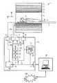
図1には、本発明による磁気共鳴装置1が略示されている。この磁気共鳴装置1は本来の磁気共鳴スキャナ2を含んでおり、その中には検査空間8つまり患者トンネル8が設られている。この患者トンネル8には寝台7を運び入れることができ、検査中、その上に寝かされた患者Oまたは発端者を、磁気共鳴スキャナ2内部の特定のポジションにおいて、その中に配置された磁石システム及び高周波システムに対し相対的に寝かせることができ、もしくは測定中、様々なポジションに移動させることができる。 FIG. 1 schematically shows a magnetic resonance apparatus 1 according to the invention. The magnetic resonance apparatus 1 includes an original
磁気共鳴スキャナ2の基本的なコンポーネントは、基本磁場磁石3と、x,y,z方向で傾斜磁場を発生させる傾斜磁場コイルを備えた傾斜磁場システム4と、全身用高周波コイル5である。x,y,z方向における傾斜磁場コイルは互いに独立して制御可能であり、所定の組み合わせに従って任意の論理的な空間方向(例えばスライス選択方向、位相エンコード方向または読み出し方向)において傾斜磁場を加えることができ、その際、これらの方向は一般には選択されたスライス方向に依存している。同様に論理的な空間方向を、x,y,z方向と一致させることもでき、例えばスライス選択方向をz方向とし、位相エンコード方向をy方向、読み出し方向をx方向とすることができる。検査対象Oに誘導された磁気共鳴信号の受信を、全身用高周波コイル5を介して行うことができ、このコイル5によって通常、磁気共鳴信号を誘導するための高周波信号も送信される。ただし一般的にこれらの信号を、例えば患者Oの上または下に配置された複数の局所コイル(これらのうち1つだけを図示)を備えた局所コイル装置6によって受信することができる。これらのすべてのコンポーネントは基本的に当業者には知られており、したがってそれらについて図1には概略的にしか示していない。 The basic components of the
磁気共鳴スキャナ2のコンポーネントは制御装置10によって制御可能である。この制御装置を制御コンピュータとすることができ、これを複数の個別のコンピュータによって構成することができ、場合によっては空間的に隔てられており適切なケーブル等によって互いに接続された複数の個別のコンピュータによって構成することができる。制御装置10は端末インタフェース17を介して端末機器30と接続されており、この端末機器30によって磁気共鳴装置1全体を制御することができる。ここに示されている実施形態によればこの端末機器30は、キーボード、1つまたは複数のディスプレイ、さらには例えばマウスといったそのほかの入力機器を備えたコンピュータとして構成されており、このようにしてオペレータにグラフィックユーザインタフェースが提供される。 The components of the
制御装置10は殊に傾斜磁場制御ユニット11を有しており、このユニット自体は複数の部分コンポーネントによって構成することができる。この傾斜磁場制御ユニット11を介して、個々の傾斜磁場コイルに対し傾斜磁場パルスシーケンスGSに従い制御信号が加えられる。これは既述のように、測定中、予め厳密に定められた時間ポジションのところに予め厳密に定められた時間経過特性によってセットされた(表された)傾斜磁場パルスである。 The
さらに制御装置10は高周波送信ユニット12を有しており、これによってパルスシーケンスMSの所定の高周波パルスシーケンスHFSに従い全身高周波コイル5にそれぞれ高周波パルスが供給される。高周波パルスシーケンスHFSは、上述の励起パルスと再集束パルスを含んでいる。そして局所コイル装置6によって磁気共鳴信号の受信が行われ、この装置により受信された生データRDが高周波受信ユニット13により読み出されて処理される。磁気共鳴信号は生データRDとしてディジタル形式で再構成ユニット14へ伝送され、再構成ユニット14は生データRDから画像データBDを再構成する。それらの画像データBDは記憶装置16に格納され、及び/又はインタフェース17を介して端末機器30へ供給されて、オペレータはそれらのデータを観察できるようになる。これらの画像データBDをネットワークNWを介して他の場所で記憶することもでき、及び/又は表示及び評価することもできる。これに対する代案として、高周波パルスシーケンスを局所コイル装置を介して送信することもでき、及び/又は磁気共鳴信号を全身高周波コイルによって受信することもでき(図示せず)、これは全身高周波コイル5及び局所コイル装置6と高周波送信ユニット12もしくは高周波受信ユニット13との結線次第で行うことができる。 Furthermore, the
さらに別のインタフェース18を介して、制御命令を磁気共鳴スキャナ2の他のコンポーネント例えば寝台7や基本磁場磁石3に伝達することができ、あるいは測定値もしくは他の情報を受け取ることができる。 Via a
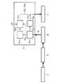
傾斜磁場制御ユニット11、高周波送信ユニット12及び高周波受信ユニット13は、測定制御ユニット15によってそれぞれコーディネートされて制御される。これにより適切な命令を通して、望ましい傾斜磁場パルスシーケンスGSと高周波パルスシーケンスHFSが送信されるようになる。しかもこれによって、適切な時点に磁気共鳴信号を局所コイル装置6の局所コイルにおいて高周波受信ユニット13により読み出して、さらに処理をすることができる。同様に測定制御ユニット15はインタフェース18も制御する。測定制御ユニット15を、例えばプロセッサまたは複数の共働するプロセッサによって構成することができる。このプロセッサに、例えば適切なソフトウェアコンポーネントとして、本発明によるパルスシーケンス最適化装置20を実装することができる。これについてはあとで詳しく説明する。 The gradient magnetic
この種の磁気共鳴測定の基本的な流れ及び(パルス最適化装置20を除き)制御のための既述のコンポーネントについては当業者に知られているので、ここではそれらについてはこれ以上詳しくは言及しない。なお、この種の磁気共鳴スキャナならびにこれに属する制御装置がさらに別の多数のコンポーネントを有することができるが、これについても同様にここでは詳しくは説明しない。ここで述べておきたいのは、磁気共鳴スキャナ2をこれとは異なるようにも構成できることであり、例えば側方が開放された患者空間にしたり、あるいは体の一部だけを配置可能な比較的小さいスキャナとして構成することもできる。 Since the basic flow of this type of magnetic resonance measurement and the components already described for control (except for the pulse optimizer 20) are known to those skilled in the art, they are referred to here in more detail here. do not do. It should be noted that this type of magnetic resonance scanner and the control device belonging to it can have a number of other components, but this is likewise not described in detail here. It should be noted here that the
測定をスタートさせるため、一般的にオペレータは端末機器30を介して、種々の測定のための多数の制御プロトコルPが格納されている記憶装置16から、この測定のために予め設けられている制御プロトコルPを選択する。この制御プロトコルPには殊に、個々の測定のための様々な制御パラメータSPが含まれている。それらの制御パラメータSPとして挙げられるのは、望ましいパルスシーケンスのために定められた基本設定であり、例えばスピンエコーシーケンスであるのか、ターボスピンエコーシーケンスであるのかといったシーケンスタイプである。さらに制御パラメータとして挙げられるのは、個々の高周波パルスによって達成すべき磁化、生データ取得のためにとるべきk空間の傾斜磁場軌跡、さらにはスライス厚、スライス間隔、スライス数、分解能、反復時間、スピンエコーシーケンスにおけるエコー時間などに関する制御パラメータである。 In order to start the measurement, the operator generally provides a control provided in advance for this measurement from the
オペレータは、目下望まれる測定に固有の制御プロトコルを作成する目的で、端末機器30を用いてこれらの制御パラメータの一部を変更することができる。この目的で、変更のために例えば端末機器30のグラフィックユーザインタフェース上に、可変の制御パラメータが提供される。 The operator can change some of these control parameters using the
なお、オペレータは、ネットワークNWを介して制御プロトコルを例えば磁気共鳴装置の製造メーカから呼び出し、それらのデータを必要に応じて変更して利用することもできる。 The operator can also call a control protocol from the manufacturer of the magnetic resonance apparatus, for example, via the network NW and change and use the data as necessary.
そして制御パラメータSPに基づきパルスシーケンスSまたは測定シーケンスが求められ、これらのシーケンスによって最終的に、他のコンポーネントの本来の制御が測定制御ユニット15によって行われる。パルスシーケンスSをパルスシーケンス算出装置において計算することができ、この装置は例えば端末機器30のコンピュータ上のソフトウェアコンポーネントとして実現することができる。ただし原理的には、パルスシーケンス算出装置を制御装置10自体の一部分としてもよく、殊に測定制御ユニット15の一部分としてもよい。同様にパルスシーケンス算出装置を、例えばネットワークNWを介して磁気共鳴装置と接続されている別個の計算システム上で実現してもよい。 Based on the control parameter SP, a pulse sequence S or a measurement sequence is obtained, and finally, the original control of other components is performed by the
パルスシーケンスSの実行にあたりこれらのパルスシーケンスSは測定ユニット15により、最初にパルスシーケンス最適化装置20において本発明によるやり方に従い最適化されてから、測定制御ユニット15のパルス送信装置19を介して供給され、最終的にパルス送信装置19は、高周波パルスシーケンスHFSを高周波送信ユニット12へ送出し、傾斜磁場パルスシーケンスGSを傾斜磁場制御ユニット11へ送出する。この目的で上述のパルスシーケンス最適化装置20は入力インタフェース21を有しており、これは本来完成しており送信準備完了状態にあるが最適化する必要のあるパルスシーケンスSを受け取って、分析ユニット22へ転送する。分析ユニット22は、固定ポイント期間と最適化が許可されている可変タイムインターバルとを識別するために、パルスシーケンスの分析を実行する。ついでパルス形状最適化ユニット23において、予め定められた最適化基準例えば1階微分に関して、可変タイムインターバルにおける傾斜磁場パルスのパルス形状が最適化される。1階微分の上述の最適化の代わりに、あるいはこれに加えて、ノイズ低減に関して他の最適化基準を用いようとするならば、オペレータはそれを例えば端末30を介して予め設定することができる。例えば記憶装置に、種々の最適化基準とそれらに属するルールを格納しておくことができ、端末30のディスプレイ上で選択させるためにそれらの最適化基準をオペレータに呈示することができる。そしてオペレータはグラフィックユーザインタフェースを介して選択を実行し、もしくはユーザインタフェースを介して対応する選択命令が登録される。 In the execution of the pulse sequence S, these pulse sequences S are first optimized by the measuring
次に図2〜図5に基づき、パルスシーケンスSの生成ならびにパルス送信装置19による出力ないしは実行(高周波パルスの送信、傾斜磁場の設定及び受信装置の作動)に至るまでのパルスシーケンスSの後続処理について例示しながら、既述のコンポーネントの詳しい動作について説明する。ここでも一例として、ノイズ低減に関して傾斜磁場パルスの1階微分の最適化を行うものとする。 Next, based on FIG. 2 to FIG. 5, subsequent processing of the pulse sequence S until generation of the pulse sequence S and output or execution by the pulse transmission device 19 (transmission of a high-frequency pulse, setting of a gradient magnetic field and operation of a reception device). A detailed operation of the above-described component will be described with reference to FIG. Here again, as an example, it is assumed that the first-order derivative of the gradient magnetic field pulse is optimized for noise reduction.
図2に描かれているように、本発明による方法はまずはステップIにおいて、通常のようにパルスシーケンスSを準備することからスタートする。すなわちここではシーケンスタイプが決定され、もしくは特定のシーケンスタイプが定義されている対応のプロトコルがサーチされる。その際、必要とされるパラメータの採用もしくは場合によってはそれらの変更がユーザによって行われる。ついでステップIIにおいて、予め設定された規定のシーケンスパラメータによるパルスシーケンスの正確なタイミングならびにフローが計算される。ステップIIIにおいて、送信準備完了状態にあるがまだ最適化されていないパルスシーケンスが、イベントブロックの形式で転送される。本発明による方法を適用しないとしたならば、ステップIIIにおいてただちにイベントブロックがパルス送信装置19へ転送され、次にパルス送信装置19はステップVにおいてイベントブロックを出力し、これによってパルスシーケンスS全体が実行されることになる。しかしながら本発明によれば、イベントブロック転送前にステップIVにおいて個々のイベントブロックが処理される。ステップII,III,IV,VにおけるパルスシーケンスSの処理は、個々のイベントブロックの形式でシーケンシャルに行われるので、これに応じてこれらのステップを時間的に並行して行うことができ、つまり後のイベントブロックがまだステップIIに存在する一方、先のイベントブロックがすでにステップVにおいてパルス送信装置19へ伝送される。 As depicted in FIG. 2, the method according to the invention starts at step I by preparing a pulse sequence S as usual. That is, the sequence type is determined here, or a corresponding protocol in which a specific sequence type is defined is searched. At that time, the necessary parameters are adopted or, if necessary, changed by the user. Then, in step II, the exact timing and flow of the pulse sequence according to the predetermined sequence parameters set in advance are calculated. In step III, a pulse sequence that is ready for transmission but not yet optimized is transferred in the form of an event block. If the method according to the invention is not applied, the event block is immediately transferred to the
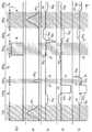
図3には、きわめて簡略化された傾斜磁場エコーシーケンスにおける最初の部分のパルスダイアグラムが例示されており、この傾斜磁場エコーシーケンスはイベントブロックEBI1,EBI2,EBI3,EBI4に分割されている(図3では最初の3つのイベントブロックだけが完全に描かれており、4番目のイベントブロックはほぼ完全に描かれている)。このようなパルスダイアグラムの場合には一般にそれぞれ異なる上下に位置する時間軸上に、読み出し窓Wと読み出すべき高周波パルスHF1,HF2,HF3と傾斜磁場パルスが、時間tに依存して示されている。ここでは一番上の読み出し時間軸ADC上に読み出し窓Wが描かれており、上から2番目の高周波パルス時間軸HFには、送信すべき高周波パルスHF1,HF2,HF3の振幅が描かれている。さらにその下の傾斜磁場パルス時間軸Gx上には、傾斜磁場パルスGx1,GX2,Gx3,Gx4,Gx5,Gx6が描かれている。これらのパルスは読み出し方向における傾斜磁場パルスである。下から2番目の傾斜磁場パルス時間軸Gy上には、傾斜磁場パルスGy1,Gy2,Gy3,Gy4,Gy5,Gy6が描かれており、これらのパルスは位相エンコード方向にスイッチされ、一番下の傾斜磁場パルス軸Gzは、スライス選択方向における傾斜磁場パルスGz1,Gz2,Gz3,Gz4,Gz5,Gz6が描かれている。時間軸のポジションはそれぞれゼロラインを表しており、つまり傾斜磁場であれば、それらのパルスの振幅が傾斜磁場パルス時間軸Gx,Gy,Gzから下へ向かって延びるか、上へ向かって延びるかに応じて、負の傾斜磁場パルス又は正の傾斜磁場パルスとすることができる。見やすくするため、すべてのパルスダイアグラムについて時間方向と振幅方向において任意の単位でスケーリングを行っている。それというのも、本発明の原理を理解するにはまず第一に、最適化前と最適化後のパルス経過特性もしくはパルス形状の比較が重要だからである。FIG. 3 illustrates a pulse diagram of the first part of a very simplified gradient echo sequence, which is divided into event blocks EBI1 , EBI2 , EBI3 , EBI4. (In FIG. 3, only the first three event blocks are completely drawn, and the fourth event block is almost completely drawn). In the case of such a pulse diagram, the readout window W, the high-frequency pulses HF1 , HF2 , HF3 and the gradient magnetic field pulse to be read out are shown depending on the time t, generally on different time axes. Has been. Here, the readout window W is drawn on the top readout time axis ADC, and the amplitude of the high frequency pulses HF1 , HF2 , and HF3 to be transmitted is shown on the second high frequency pulse time axis HF from the top. It is drawn. Further, gradient magnetic field pulses Gx1 , GX2 , Gx3 , Gx4 , Gx5 , Gx6 are drawn on the gradient magnetic field pulse time axis Gx therebelow. These pulses are gradient magnetic field pulses in the readout direction. On the second gradient magnetic field pulse time axis Gy from the bottom, gradient magnetic field pulses Gy1 , Gy2 , Gy3 , Gy4 , Gy5 and Gy6 are drawn, and these pulses are switched in the phase encoding direction. On the lowermost gradient magnetic field pulse axis Gz, gradient magnetic field pulses Gz1 , Gz2 , Gz3 , Gz4 , Gz5 , Gz6 in the slice selection direction are drawn. Each position of the time axis represents a zero line, that is, if the magnetic field is a gradient magnetic field, whether the amplitude of those pulses extends downward or upward from the gradient magnetic field pulse time axis Gx, Gy, Gz Depending on, it can be a negative gradient pulse or a positive gradient pulse. For ease of viewing, all pulse diagrams are scaled in arbitrary units in the time and amplitude directions. This is because, in order to understand the principle of the present invention, first of all, it is important to compare the pulse characteristics or pulse shapes before and after optimization.
このパルスシーケンスSの第1のイベントブロックEBI1は、脂肪(信号)抑制を生じさせるイベントブロックEBI1である。このため最初に比較的強い高周波パルスHF1が送信される一方、傾斜磁場パルスは実行されず、その結果、高周波パルスHF1はスライス選択として作用しない。しかしこれらの高周波パルスHF1の終了に続いて、3つの空間軸すべてにおいて3つの傾斜磁場パルスGx1,Gy1,Gz1が生じ、これらは意図に反して脂肪(信号)抑制によって形成された横方向の磁化を分散(ディフェーズ dephase)するために用いられる。First event block EBI1 of the pulse sequence S is an event block EBI1 to produce fat (signal) suppression. For this reason, a relatively strong high-frequency pulse HF1 is transmitted first, while no gradient magnetic field pulse is executed, so that the high-frequency pulse HF1 does not act as a slice selection. However, following the end of these high-frequency pulses HF1 , three gradient magnetic field pulses Gx1 , Gy1 , Gz1 occur in all three spatial axes, which were formed by fat (signal) suppression unintentionally. Used to disperse transverse magnetization (dephase).
次のイベントブロックEBI2はプレスポイラーとして用いられる。このイベントブロックEBI2において、2つの負の傾斜磁場パルスGy2,Gz2がy方向とz方向にスイッチされる。これらのパルスは、場合によっては存在する横方向の残留磁化の位相を効果的にずらすために用いられる。このような残留磁化は、先行の励起または傾斜磁場によって生成され、もしくは再集束された可能性がある。The next event block EBI2 is used as a press spoiler. In this event block EBI2 , the two negative gradient magnetic field pulses Gy2 and Gz2 are switched in the y direction and the z direction. These pulses are used to effectively shift the phase of the transverse residual magnetization that may be present. Such residual magnetization may have been generated or refocused by prior excitation or gradient fields.
3番目のイベントブロックEBI3には傾斜磁場エコーシーケンスが含まれており、この場合、特定のボリュームもしくは特定のスライスにおいて磁気共鳴信号が取得され、この取得は、規定の傾斜磁場Gz3をスライス選択方向Gzで同時に出力しながら高周波パルスHF2によって励起し、ついで特定の傾斜磁場Gx3を読み出し方向Gxにスイッチして読み出し窓Wをセットし、つまりADC(アナログ/ディジタル変換器)を受信にスイッチすることによって行われる。このイベントブロックEBI3には別の傾斜磁場パルスGz4,Gx2,Gy3,Gx4,Gy4が存在し、これらの傾斜磁場パルスは、後続のイベントブロックに意図しないエコーを発生させないようにする目的で、励起パルスにより生成された横方向磁化の位相をずらすために用いられる。The third event block EBI3 contains a gradient echo sequence, in which case a magnetic resonance signal is acquired in a specific volume or a specific slice, this acquisition being a slice selection of a defined gradient magnetic field Gz3 Simultaneously output in the direction Gz and excited by the high frequency pulse HF2 , then switch the specific gradient magnetic field Gx3 in the readout direction Gx and set the readout window W, that is, switch the ADC (analog / digital converter) to reception Is done by doing. In this event block EBI3, there are other gradient magnetic field pulses Gz4 , Gx2 , Gy3 , Gx4 , and Gy4 , so that these gradient magnetic field pulses do not cause unintended echoes in subsequent event blocks. It is used to shift the phase of the transverse magnetization generated by the excitation pulse.
傾斜磁場エコーイベントブロックEBI3の次にさらに飽和イベントブロックEBI4が続き、このイベントブロックは最初に、パラレルに3つの傾斜磁場パルスGx5,Gy5,Gz5がx方向、y方向、z方向にスイッチされることから始まり、その後、スライス選択でない高周波パルスHF3が送信される。この場合、すべての傾斜磁場はゼロにセットされており、ついで再び3つのすべての空間方向で別の傾斜磁場パルスGx6,Gy6,Gz6が送信される。その後、さらに別のイベントブロックが続き、例えば新たなプレスポイラー、付加的な反復、傾斜磁場エコーイベントブロック等が続く。The gradient magnetic field echo event block EBI3 is followed by a saturation event block EBI4, which first has three gradient magnetic field pulses Gx5 , Gy5 , Gz5 in the x, y and z directions in parallel. The high-frequency pulse HF3 that is not slice-selected is then transmitted. In this case, all gradient fields are set to zero and then another gradient field pulse Gx6 , Gy6 , Gz6 is transmitted again in all three spatial directions. Then another event block follows, for example a new press spoiler, additional iterations, gradient echo event block, etc.
既述のイベントブロックEBI1,EBI2,EBI3,EBI4の各々は、すぐにわかるように、基本的には最適化可能な期間を含んでいる。ここではそれらは上述の判定基準に当てはまらない期間であり、例えば高周波パルスHF1,HF2,HF3のうちの1つまたは読み出し窓Wとパラレルに送信される傾斜磁場などである。たいていは変更できない特定の傾斜磁場パルス例えばフローコンペンセーション傾斜磁場パルス、フュージョン傾斜磁場パルスあるいはノック傾斜磁場パルスなどは、ここに示した簡略化されたシーケンスには含まれていない。Each of the event blocks EBI1 , EBI2 , EBI3 , and EBI4 described above basically includes a period that can be optimized. Here, they are periods that do not meet the above-mentioned criteria, such as one of the high-frequency pulses HF1 , HF2 , HF3 or a gradient magnetic field transmitted in parallel with the readout window W. Certain gradient magnetic field pulses that are usually not changeable, such as flow compensation gradient pulses, fusion gradient pulses or knock gradient pulses, are not included in the simplified sequence shown here.
他方、プレスポイラーイベントブロックEBI2を除いて、他のすべてのイベントブロックEBI1,EBI3,EBI4には固定ポイント期間も含まれており、これらの期間では、傾斜磁場振幅値の変更は許可されておらず、したがってこれらは最適化から除外しなければならない。このため図2に示されているように、最初にステップIVのうち第1のサブステップIVaにおいて、変更不可能な固定ポイント期間が含まれるのか、及び変更可能もしくは最適化可能なタイムインターバルが含まれるのかについて、到来したイベントブロックEBIが検査される。このステップIVaにおいて、送出イベントブロックEBAF,EBA0へのパルスシーケンスSの新たな分割も行われる。On the other hand, except for the pre-spoiler event block EBI2 , all other event blocks EBI1 , EBI3 , EBI4 also include a fixed point period, during which the change of the gradient magnetic field amplitude value is permitted. They are not, and therefore must be excluded from the optimization. Therefore, as shown in FIG. 2, first, in the first sub-step IVa of step IV, a fixed point period that cannot be changed is included, and a time interval that can be changed or optimized is included. The incoming event block EBI is checked for In step IVa, a new division of the pulse sequence S into the transmission event blocks EBAF and EBA0 is also performed.
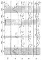
図4にはこのことが、図3に示したパルスシーケンスSに関して描かれている。ここでは、最適化不可能な固定ポイント期間がそれぞれハッチングパターンによって覆われており、最適化可能なタイムインターバルは覆われていない。これによって自動的に新たな送出イベントブロックEBA1,EBA2,...,EBA8が生じ、これらの送出イベントブロックEBA1,EBA2,...,EBA8には、固定ポイント期間IFあるいは最適化可能なタイムインターバルI0がちょうど1つずつ含まれている。ここでは最適化不可能な期間として、パラレルに高周波パルスHF1,HF2,HF3が送出されるかまたは読み出し窓Wがスイッチされる期間がきちんと識別されている。これらの領域では、厳密に予め定められた振幅値のところに傾斜磁場が留まっていなければならない。それらの間に位置する領域では、以下の境界条件のもとでパルス形状もしくは傾斜磁場経過特性を任意に変更してよい。すなわち、最適化不可能な固定ポイント期間IFを含む隣接イベントブロックとの境界ポイントでは振幅値が保持され、それらの境界ポイントでは1階微分がゼロであり、最適化可能な個々の期間I0内における傾斜磁場パルスのモーメント全体は最適化の前と後で等しい。最適化可能なイベントブロックEBA2,EBA4,EBA6,EBA8は、次のステップIVbにおいて上述の境界条件のもとで最適化される(図2ではこれらの最適化可能なイベントブロックは総括して参照符号EBA0として描かれている)。This is illustrated in FIG. 4 for the pulse sequence S shown in FIG. Here, the fixed point periods that cannot be optimized are each covered by a hatching pattern, and the time intervals that can be optimized are not covered. This automatically causes new outgoing event blocks EBA1 , EBA2 ,. . . , EBA8 occur and these send event blocks EBA1 , EBA2 ,. . . , The EBA8 are included fixed point time IF or optimizable time interval I0 exactly one each. Here, the period in which the high-frequency pulses HF1 , HF2 , HF3 are sent in parallel or the readout window W is switched is properly identified as the period that cannot be optimized. In these regions, the gradient magnetic field must remain exactly at a predetermined amplitude value. In the region located between them, the pulse shape or gradient magnetic field course characteristics may be arbitrarily changed under the following boundary conditions. That is, in the boundary points of the adjacent event block comprising optimizing non fixed point time IF held amplitude values, a zero first derivative in those boundary points, individual optimization period I0 The total moment of the gradient pulse in is equal before and after optimization. The optimizable event blocks EBA2 , EBA4 , EBA6 , EBA8 are optimized under the above boundary conditions in the next step IVb (in FIG. 2 these optimizable event blocks are summarized. And is drawn as reference EBA0 ).
ついで、既述のスプライン補間法を適用して最適化が行われる。この場合、境界における振幅値はそれぞれ固定ポイントFPとみなされ、既述の境界条件(固定ポイントの達成、固定ポイントにおける1階微分=0、曲線下の積分値の保持)のもとでスプラインが行われて、個々の最適化可能な期間I0において望ましい円滑なパルス形状が生じる。Next, optimization is performed by applying the spline interpolation method described above. In this case, the amplitude value at the boundary is regarded as a fixed point FP, and the spline is generated under the above-described boundary conditions (achieving the fixed point, first-order differentiation at the fixed point = 0, holding the integral value under the curve). Done, the desired smooth pulse shape occurs in each optimizable period I0 .
図5にはこのことが、図4に示したパルスシーケンスに関して描かれている。殊にここできわめてはっきりと示されているのは、互いに隣り合う急峻な側縁を有する比較的矩形のパルスが、部分的に互いにクロスオーバーしている共通のパルス形状を有する傾斜磁場パルスGx1′,Gx2′,Gx3′,Gx4′,Gx5′,Gy1′,Gy2′,Gy3′,Gy4′,Gz1′,Gz2′,Gz3′,Gz4′,Gz5′,Gz6′に変換されている様子である。これらの傾斜磁場パルスは比較的滑らかであり、したがって傾斜磁場コイルに対しきわめて僅かな負荷しかもたらさず、したがって煩わしいノイズが格段に抑えられる。傾斜磁場パルスをこのようにマージする例として挙げられるのは例えば、図3及び図4に示した元のパルスシーケンスSにおける傾斜磁場パルスGy1,Gy2が、最適化されたパルスシーケンスにおいて1つの共通の傾斜磁場パルスGy1'にマージされていること、同じように、傾斜磁場パルスGz1〜Gz3がここでは1つの共通のパルス形状Gz1',Gz2',Gz3'に置き換えられていること、しかもそれが3つのイベントブロックEBA2,EBA3,EBA4を越えて広がっていることである。特にここで留意したいのは、スライス選択の高周波パルスHF2がパラレルに送出されるイベントブロックEBA3の期間中、傾斜磁場振幅が変化していないことであり、つまり厳密にこの領域内では、パルスGz3の元の部分がここではイベントブロックEBA3内に存在する傾斜磁場パルスGz2'と正確に一致していることである。This is illustrated in FIG. 5 for the pulse sequence shown in FIG. Particularly clearly shown here is a gradient pulse Gx1 having a common pulse shape in which relatively rectangular pulses having steep side edges adjacent to each other partially cross over each other. ′, Gx2 ′, Gx3 ′, Gx4 ′, Gx5 ′, Gy1 ′, Gy2 ′, Gy3 ′, Gy4 ′, Gz1 ′, Gz2 ′, Gz3 ′, Gz4 ′, The state is converted to Gz5 ′ and Gz6 ′. These gradient magnetic field pulses are relatively smooth, and therefore introduce very little load on the gradient coil, so that annoying noise is greatly suppressed. As an example of merging gradient magnetic field pulses in this way, for example, the gradient magnetic field pulses Gy1 and Gy2 in the original pulse sequence S shown in FIG. 3 and FIG.'that have been merged in the same manner, the gradient magnetic field pulses Gz1 ~Gz3 common pulse shape Gz 1 onehere' common gradient pulse Gy 1,
図3〜図5から明らかになるのは、本発明による方法によって効果的に、各パルスシーケンスが著しく迅速に実行直前に、ノイズの発生や傾斜磁場コイルの負荷に関して最適化できることであり、その際、タイミングのいかなる変更も不要であり、したがってこれに付随して画像品質に変化がもたらされることもない。 3 to 5, it is clear that the method according to the invention can effectively optimize each pulse sequence with respect to noise generation and gradient coil loading just before execution, very quickly. , No change in timing is required and therefore no concomitant changes in image quality.
特に長い反復時間を伴うプロトコルあるいは予備パルスまたは測定インターバルの後に特に長い休止を伴うプロトコルが用いられ、これに加えて傾斜磁場スポイラーが適用される場合であると、休止期間全体にわたり傾斜磁場がマージされることによって、意図するスポイルが阻止される可能性がある。図6には傾斜磁場パルスシーケンスのある区間において、このようにスポイラーパルスが意図することなく長く延びすぎてしまう様子が示されている。 If a protocol with a particularly long repetition time or a protocol with a particularly long pause after a pre-pulse or measurement interval is used and in addition a gradient spoiler is applied, the gradient fields are merged throughout the pause period. This may prevent the intended spoil. FIG. 6 shows a state in which the spoiler pulse extends too long unintentionally in a certain section of the gradient magnetic field pulse sequence.
この場合、本発明によればスプライン補間法を用いることによって、傾斜磁場パルスG′が比較的幅の広いインターバルIにわたって延びている。このような珍しい作用を完全に排除できるようにする目的で、簡単なやり方によれば別の境界条件を予め与えることができ、これによればモーメントの平均値がタイムインターバルIGにわたってチェックされ、この値が定められた値を下回れば、図7に示されているように、単純にタイムインターバルIG全体を2つのサブタイムインターバルI1,I2に分割する。次に、複数のサブタイムインターバルのうち一方のサブタイムインターバル(図7ではサブタイムインターバルI2)が傾斜磁場振幅ゼロにセットされ、ついで最適化は他方のサブタイムインターバルI1についてのみ行われる。その結果、側縁勾配が小さくなり最適化前のパルスよりも改善されたパルス形状をもつ傾斜磁場パルスG″も生成されるが、その際に同時に、このインターバル内の単位時間あたりのモーメント全体が、スポイラー効果を達成するのに十分な大きさとなるよう配慮される。In this case, according to the present invention, the gradient magnetic field pulse G ′ extends over a relatively wide interval I by using the spline interpolation method. In order to be able to completely eliminate such unusual effects, another simple boundary condition can be given in advance according to a simple method, whereby the mean value of the moment is checked over the time interval IG , If this value falls below a predetermined value, the entire time interval IG is simply divided intotwo sub-time intervals I1 and I2 as shown in FIG. Next, one of the plurality of sub-time intervals (sub-time interval I2 in FIG. 7) is set to zero gradient magnetic field amplitude, and then optimization is performed only for the other sub-time interval I1 . As a result, a gradient gradient pulse G ″ having a smaller side edge gradient and an improved pulse shape than the pulse before optimization is also generated, and at the same time, the entire moment per unit time in this interval is also reduced. Care is taken to ensure that it is large enough to achieve the spoiler effect.
その後、次のステップIVcにおいて、最適化されたイベントブロックEBAO′が、システム固有の特定のパラメータSSPを遵守しているか否かについてチェックされ、例えばそれらのイベントブロックが個々の磁気共鳴装置に関して最大許容傾斜磁場振幅よりも低いか否かについて、ならびに最大許容スルーレートが守られているか否かについてチェックされる。これがあてはまらなければ、破線で表されているように、最適化されたイベントブロックEBAO′が再び元のイベントブロックEBAOに置き換えられる。ただし通常は、最適化されたイベントブロックEBAO′がこれらの条件を遵守していると想定できる。システム固有のパラメータSSPを例えば記憶装置に格納しておくことができる。次に、最適化されたイベントブロックEBAO′(または固有のケースでは最適化されないイベントブロックEBAO′)は、ステップVにおいてパルス送信装置19へ転送されて実行される。この場合、パルス送信装置は、最適化不可能なイベントブロックEBAFも適合された順序で実行されるよう配慮する。この目的でパルス送信装置19へ、個々の最適化されたイベントブロックEBAO′もしくは最適化可能なイベントブロックEBAO及び最適化不可能なイベントブロックEBAFが、適合された時間順序で転送される。例えばこの場合、最適化不可能なイベントブロックEBAFは遅延ステップIVdにおいて遅延され、したがってそれらのイベントブロックは適合された時点になってはじめて転送されるようになる。Thereafter, in a next step IVc, the optimized event blocks EBAO ′ are checked for compliance with certain system-specific parameters SSP, for example those event blocks are maximized for the individual magnetic resonance apparatus. It is checked whether it is below the allowable gradient field amplitude and whether the maximum allowable slew rate is observed. If this is not the case, the optimized event block EBAO ′ is again replaced with the original event block EBAO , as represented by the dashed line. Usually, however, it can be assumed that the optimized event block EBAO 'complies with these conditions. The system-specific parameter SSP can be stored in a storage device, for example. Next, the optimized event block EBAO ′ (or event block EBAO ′ not optimized in the specific case) is transferred to the
ステップIVaについても説明しておくと、パルスシーケンスSはその時間経過において最初に2つの異なるカテゴリーに分割され、つまり最適化可能なイベントブロックと最適化不可能なイベントブロックとに分割される。例えば高周波パルスまたは読み出し窓が加わると、対応するタイムインターバルがカテゴリー0=「最適化不可能」に割り当てられるのに対し、この種の高周波パルス又は読み出し窓がなく、パルスシーケンスSにおいてそれらの間に位置するインターバルは、カテゴリー1=「最適化可能」に割り当てられる。ついでタイムインターバル(最適化可能なイベントブロック及び最適化不可能なイベントブロック)[0,t1],[t1,t2],[t2,t3]等が、カテゴリー0とカテゴリー1とで交互に発生する。その後、カテゴリー1のタイムインターバルは、既述のように例えばスプライン補間法によって最適化される。この場合、計算されたスプラインカーブによって、このインターバル内のすべてのパルスの元の経過が置き換えられるので、傾斜磁場カーブのモーメントつまりはスピンフェーズに対する作用は一定であり、同時にカーブは常に微分可能なまま維持される。Step IVa will also be described. The pulse sequence S is first divided into two different categories in the course of time, that is, event blocks that can be optimized and event blocks that cannot be optimized. For example, when a high frequency pulse or readout window is added, the corresponding time interval is assigned to
最後にもう一度述べておくと、これまで詳しく説明してきた方法ならびに構成は実施例であって、請求項によって規定されているかぎりおいて、本発明の範囲から逸脱することなく、その基本原理を広い範囲にわたって変更することも可能である。特に述べておきたいのは、本発明による方法を任意のパルスシーケンスに適用できることである。さらに完全を期すために述べておくと、不定冠詞を用いたからといって、該当する特徴が複数存在し得ることを排除するものではない。同様に、「ユニット」または「モジュール」という用語は、それらが複数のコンポーネントから成り、場合によっては空間的に分散させることも可能であることを排除するものではない。 Finally, once again, the methods and configurations described in detail so far are examples, and as long as they are defined by the claims, their basic principles can be broadly defined without departing from the scope of the present invention. It is also possible to change over the range. Of particular note is that the method according to the invention can be applied to any pulse sequence. For the sake of completeness, the use of the indefinite article does not exclude the fact that there can be multiple relevant features. Similarly, the terms “unit” or “module” do not exclude that they are comprised of a plurality of components, possibly even spatially distributed.
符号の説明
1 磁気共鳴装置
2 磁気共鳴スキャナ
3 基本磁場磁石
4 傾斜磁場システム
5 全身高周波コイル
6 局所コイル装置
7 寝台
8 患者トンネル
10 制御装置
11 傾斜磁場制御ユニット
12 高周波送信ユニット
13 高周波受信ユニット
14 再構成ユニット
15 測定制御ユニット
16 記憶装置
17 端末インタフェース
18 インタフェース
19 パルス送信装置
20 パルスシーケンス最適化装置
21 入力インタフェース
22 分析ユニット
23 パルス形状最適化ユニット
30 端末
S パルスシーケンス
O 患者
P 制御プロトコル
NW ネットワーク
BD 画像データ
RD 生データ
SP 制御パラメータ
SSP システム固有のパラメータ
GS 傾斜磁場パルスシーケンス
HFS 高周波パルスシーケンス
t 時間
ADC 読み出し時間軸
W 読み出し窓
HF 高周波パルス時間軸
HF1,HF2,HF3 高周波パルス
Gx,Gy,Gz 傾斜磁場パルス時間軸
Gx1,Gx2,Gx3,Gx4,Gx5,Gx6 傾斜磁場パルス
Gx1′,Gx2′,Gx3′,Gx4′,Gx5′ 傾斜磁場パルス
Gy1,Gy2,Gy3,Gy4,Gy5,Gy6 傾斜磁場パルス
Gy1′,Gy2′,Gy3′,Gy4′ 傾斜磁場パルス
Gz1,Gz2,Gz3,Gz4,Gz5,Gz6 傾斜磁場パルス
Gz1′,Gz2′,Gz3′,Gz4′,Gz5′,Gz6′ 傾斜磁場パルス
FP 固定ポイント
EBI,EBI1,EBI2,EBI3,EBI4 到来するイベントブロック
EBAF,EBAO,EBA1,EBA2,...,EBA8 送出されるイベントブロック
EBAO′ 最適化されたイベントブロック
IF 固定ポイント期間
IO 最適化可能なタイムインターバル
G′,G″ 傾斜磁場パルス
IG インターバル
I1,I2 サブタイムインターバルDESCRIPTION OF SYMBOLS 1 Magnetic resonance apparatus 2 Magnetic resonance scanner 3 Basic magnetic field magnet 4 Gradient magnetic field system 5 Whole body high frequency coil 6 Local coil apparatus 7 Bed 8 Patient tunnel 10 Control apparatus 11 Gradient magnetic field control unit 12 High frequency transmission unit 13 High frequency reception unit 14 Re Configuration Unit 15 Measurement Control Unit 16 Storage Device 17 Terminal Interface 18 Interface 19 Pulse Transmitter 20 Pulse Sequence Optimization Device 21 Input Interface 22 Analysis Unit 23 Pulse Shape Optimization Unit 30 Terminal S Pulse Sequence O Patient P Control Protocol NW Network BD Image Data RD Raw data SP Control parameters SSP System specific parameters GS Gradient magnetic field pulse sequence HFS High frequency pulse sequence t Time ADC reading Extrusion time axis W Reading window HF High frequency pulse time axis HF1 , HF2 , HF3 High frequency pulse Gx, Gy, Gz Gradient magnetic field pulse time axis Gx1 , Gx2 , Gx3 , Gx4 , Gx5 , Gx6 inclination magnetic field pulsesGx 1 ', Gx 2', Gx 3 ', Gx 4', Gx 5 ' gradient pulseGy 1, Gy 2, Gy 3 , Gy 4, Gy 5, Gy 6 gradient pulse Gy1', Gy2 ′, Gy3 ′, Gy4 ′ Gradient magnetic field pulses Gz1 , Gz2 , Gz3 , Gz4 , Gz5 , Gz6 Gradient magnetic field pulses Gz1 ′, Gz2 ′, Gz3 ′, Gz4 ′, Gz5 ′, Gz6 ′ Gradient magnetic field pulse FP fixed point EBI, EBI1 , EBI2 , EBI3 , EBI4 arriving event blocks EBAF , EBAO , EBA1 , EBA2 ,. . . , EBA8 sent event block EBAO ′ optimized event block IF fixed point period IO Optimizeable time interval G ′, G ″ Gradient field pulseIG interval I1 , I2 sub time interval
Claims (15)
Translated fromJapanese複数の高周波パルス(HF1,HF2,HF3)と、該高周波パルスに対し時間的に整合された複数の傾斜磁場パルス(Gx1,...,Gx6,Gy1,...,Gy6,Gz1,...,Gz6)とを含むパルスシーケンス(S)を受け取るステップと、
前記パルスシーケンス(S)において不変のまま保持すべき固定ポイント期間(IF)と、前記パルスシーケンス(S)において最適化が許可される可変タイムインターバル(IO)とを識別するために、前記パルスシーケンス(S)を自動的に分析するステップと、
前記可変タイムインターバル(IO)内の傾斜磁場パルス(Gx1′,...,Gx4′,Gy1′,...,Gy3′,Gz1′,...,Gz6′,G′,G″)を、予め定められた最適化基準に従い、有利には前記タイムインターバル(IO)の長さを一定に保持しながら、自動的に最適化するステップと
を有することを特徴とする、
磁気共鳴装置(1)のためのパルスシーケンスを最適化する方法。In a method for optimizing a pulse sequence (S) for a magnetic resonance apparatus (1),
A plurality of radio frequency pulses (HF1 , HF2 , HF3 ) and a plurality of gradient magnetic field pulses (Gx1 ,..., Gx6 , Gy1 ,. Gy6, Gz1, ..., receiving a pulse sequence (S) comprising a Gz6) and,
In order to identify a fixed point period (IF ) that should be kept unchanged in the pulse sequence (S) and a variable time interval (IO ) that is allowed to be optimized in the pulse sequence (S), Automatically analyzing the pulse sequence (S);
Gradient magnetic field pulses (Gx1 ′,..., Gx4 ′, Gy1 ′,..., Gy3 ′, Gz1 ′,..., Gz6 ′, within the variable time interval (IO ) Automatically optimizing G ′, G ″) according to a predetermined optimization criterion, preferably while keeping the length of the time interval (IO ) constant. And
A method for optimizing a pulse sequence for a magnetic resonance apparatus (1).
該パルス送信装置(19)へ伝達する前に、前記パルスシーケンス(S)の到来イベントブロック(EBI,EBI1,...,EBI4)を分析し、個々のイベントブロック(EBI,EBI1,...,EBI4)において固定ポイント期間(IF)と可変タイムインターバル(IO)とを識別し、
前記分析に従い前記パルスシーケンス(S)を再分割して送出イベントブロック(EBA,EBA1,...,EBA8)を形成する、
請求項1または2記載の方法。The pulse sequence (S), temporally one after event block(EBA, EBA 1, ..., EBA 8) transmitted as a pulse transmission device (19),
Prior to transmission to the pulse transmitter (19), the incoming event blocks (EBI, EBI1 ,..., EBI4 ) of the pulse sequence (S) are analyzed and the individual event blocks (EBI, EBI1 , ..., EBI4 ) to identify a fixed point period (IF ) and a variable time interval (IO ),
Subdividing the pulse sequence (S) according to the analysis to form a send event block (EBA, EBA1 ,..., EBA8 ),
The method according to claim 1 or 2.
高周波パルス(HF1,HF2,HF3)の送信、
生データの読み出し、
フローコンペンセーション傾斜磁場パルスのスイッチ、
拡散傾斜磁場パルスのスイッチ、
ノック傾斜磁場パルスのスイッチ、
のうち少なくとも1つのイベントが行われるならば、
該パルスシーケンス(S)内の該期間を少なくとも固定ポイント期間(IF)として識別する、
請求項1から3のいずれか1項記載の方法。If at least one of the following events takes place according to one pulse sequence (S) within one period: transmission of high-frequency pulses (HF1 , HF2 , HF3 ),
Reading raw data,
Flow compensation gradient magnetic field pulse switch,
Switch of diffusion gradient magnetic field pulse,
Knock gradient magnetic field pulse switch,
If at least one of the events occurs,
Identifying the period in the pulse sequence (S) as at least a fixed point period (IF );
4. A method according to any one of claims 1 to 3.
高周波パルス送信時間の分析、
読み出し時間の分析、
傾斜磁場パルス(Gx1,...,Gx6,Gy1,...,Gy6,Gz1,...,Gz6)の形状の分析、
1つのイベントブロックパラメータセットに含まれている識別子の分析、
のうち少なくとも1つの手順により識別する、
請求項1から4のいずれか1項記載の方法。Identifying a period in a pulse sequence as a fixed point period (IF ) or a variable time interval (IO ) by at least one of the following procedures: analysis of radio frequency pulse transmission time;
Readout time analysis,
Analysis of the shape of gradient magnetic field pulses (Gx1 ,..., Gx6 , Gy1 ,..., Gy6 , Gz1 ,..., Gz6 )
Analysis of identifiers contained in one event block parameter set,
Identified by at least one of the steps
5. A method according to any one of claims 1 to 4.
該傾斜磁場パルス(Gx1,...,Gx6,Gy1,...,Gy6,Gz1,...,Gz6)のモーメントを一定に保持する、
及び/又は
該傾斜磁場パルスを、規定された固定ポイント(FP)のところで一定に保持する、なお該固定ポイント(FP)は有利には少なくとも、隣接する固定ポイント期間(IF)に対する可変タイムインターバル(IO)のインターバル境界における境界値を含んでいる、
請求項1から5のいずれか1項記載の方法。In optimizing the pulse shape of gradient magnetic field pulses (Gx1 ,..., Gx6 , Gy1 ,..., Gy6 , Gz1 ,..., Gz6 ),
The moment of the gradient magnetic field pulses (Gx1 ,..., Gx6 , Gy1 ,..., Gy6 , Gz1 ,..., Gz6 ) is kept constant.
And / or holding the gradient pulses constant at a defined fixed point (FP), wherein the fixed point (FP) is preferably at least a variable time interval with respect to an adjacent fixed point period (IF ) Contains boundary values at interval boundaries of (IO ),
6. A method according to any one of claims 1-5.
複数のサブタイムインターバル(I1,I2)への分割を行い、該サブタイムインターバルの一部(I1)だけに前記方向で傾斜磁場パルス(G″)が存在するよう、パルス形状(P)を最適化する、
請求項1から7のいずれか1項記載の方法。In one time interval (IG ), check whether the total moment per unit time of the gradient magnetic field pulse in one direction is smaller than a predetermined limit value,
Division into a plurality of sub-time intervals (I1 , I2 ), and a pulse shape (P ”so that a gradient magnetic field pulse (G ″) exists in the direction only in a part (I1 ) of the sub-time interval. )
8. A method according to any one of claims 1 to 7.
最初に、請求項1から11のいずれか1項記載の方法によってパルスシーケンス(S)を最適化し、次に、最適化されたパルスシーケンスを用いて前記磁気共鳴装置(1)を動作させることを特徴とする方法。In a method for operating a magnetic resonance apparatus (1),
First, the pulse sequence (S) is optimized by the method according to any one of claims 1 to 11, and then the magnetic resonance apparatus (1) is operated using the optimized pulse sequence. Feature method.
複数の高周波パルス(HF1,HF2,HF3)と、該高周波パルスに対し時間的に整合された傾斜磁場パルス(Gx1,...,Gx6,Gy1,...,Gy6,Gz1,...,Gz6,Gx1′,...,Gx4′,Gy1′,...,Gy3′,Gz1′,...,Gz6′,G′,G″)とを含むパルスシーケンス(S)を受け取る入力インタフェース(21)と、
前記パルスシーケンス(S)において不変のまま保持すべき固定ポイント期間(IF)と、前記パルスシーケンス(S)において最適化が許可される可変タイムインターバル(IO)とを識別するために、前記パルスシーケンス(S)を分析する分析ユニット(22)と、
前記可変タイムインターバル(IO)内の傾斜磁場パルス(Gx1,...,Gx6,Gy1,...,Gy6,Gz1,...,Gz6,Gx1′,...,Gx4′,Gy1′,...,Gy3′,Gz1′,...,Gz6′,G′,G″)を、予め定められた最適化基準に従い、有利には前記タイムインターバル(IO)の長さを一定に保持しながら、最適化するパルス最適化ユニット(23)と
を含むことを特徴とする、
磁気共鳴装置(1)のためのパルスシーケンス(S)を最適化するパルスシーケンス最適化装置(20)。In a pulse sequence optimization device (20) for optimizing the pulse sequence (S) for the magnetic resonance apparatus (1),
A plurality of high-frequency pulses(HF 1, HF 2, HF 3), the gradient magnetic field pulses (Gx1 to the high-frequency pulse to have been timealigned, ..., Gx 6, Gy 1 , ..., Gy 6 , Gz1 , ..., Gz6 , Gx1 ', ..., Gx4 ', Gy1 ', ..., Gy3 ', Gz1 ', ..., Gz6 ', G ', An input interface (21) for receiving a pulse sequence (S) including G ″);
In order to identify a fixed point period (IF ) that should be kept unchanged in the pulse sequence (S) and a variable time interval (IO ) that is allowed to be optimized in the pulse sequence (S), An analysis unit (22) for analyzing the pulse sequence (S);
The variable time interval (IO) gradient magnetic field pulses (Gx1in, ..., Gx 6, Gy 1 , ..., Gy 6, Gz 1, ..., Gz 6, Gx 1 ', .. , Gx4 ', Gy1 ', ..., Gy3 ', Gz1 ', ..., Gz6 ', G', G ") according to a predetermined optimization criterion, A pulse optimization unit (23) for optimizing while maintaining the length of the time interval (IO ) constant,
A pulse sequence optimization device (20) for optimizing the pulse sequence (S) for the magnetic resonance apparatus (1).
高周波送信システム(3)と、
傾斜磁場システム(4)と、
要求された測定を実行するために、予め定められたパルスシーケンス(S)に基づき前記高周波送信システム(3)及び前記傾斜磁場システム(4)を制御するように構成されている制御装置(15)と、
請求項13記載のパルスシーケンス最適化装置(20)と
が設けられていることを特徴とする、
磁気共鳴装置(1)。In the magnetic resonance apparatus (1),
A high-frequency transmission system (3);
A gradient magnetic field system (4);
A control device (15) configured to control the radio frequency transmission system (3) and the gradient magnetic field system (4) based on a predetermined pulse sequence (S) in order to perform the requested measurement. When,
A pulse sequence optimization device (20) according to claim 13 is provided,
Magnetic resonance apparatus (1).
該パルスシーケンス最適化装置(20)においてプログラムが実行されると、請求項1から12のいずれか1項記載の方法のすべてのステップを実行させるプログラムコードセクションを備えている、
コンピュータプログラム。It can be loaded directly into the storage device of the pulse sequence optimization device (20),
13. A program code section that, when executed in the pulse sequence optimization device (20), causes all steps of the method according to any one of claims 1 to 12 to be executed,
Computer program.
Applications Claiming Priority (2)
| Application Number | Priority Date | Filing Date | Title |
|---|---|---|---|
| DE102013202559.9 | 2013-02-18 | ||
| DE102013202559.9ADE102013202559B3 (en) | 2013-02-18 | 2013-02-18 | Optimization of an MR pulse sequence by automatic optimization of gradient pulses in variable intervals |
Publications (2)
| Publication Number | Publication Date |
|---|---|
| JP2014155843Atrue JP2014155843A (en) | 2014-08-28 |
| JP6274899B2 JP6274899B2 (en) | 2018-02-07 |
Family
ID=51264154
Family Applications (1)
| Application Number | Title | Priority Date | Filing Date |
|---|---|---|---|
| JP2014028513AExpired - Fee RelatedJP6274899B2 (en) | 2013-02-18 | 2014-02-18 | Method for optimizing pulse sequence for magnetic resonance apparatus, pulse sequence optimization apparatus for optimizing pulse sequence for magnetic resonance apparatus, magnetic resonance apparatus and computer program |
Country Status (5)
| Country | Link |
|---|---|
| US (1) | US9684048B2 (en) |
| JP (1) | JP6274899B2 (en) |
| KR (1) | KR101644364B1 (en) |
| CN (1) | CN103995243B (en) |
| DE (1) | DE102013202559B3 (en) |
Cited By (1)
| Publication number | Priority date | Publication date | Assignee | Title |
|---|---|---|---|---|
| JP2017070508A (en)* | 2015-10-07 | 2017-04-13 | 株式会社日立製作所 | Method of adjusting gradient magnetic field waveform of magnetic resonance imaging apparatus, and magnetic resonance imaging apparatus |
Families Citing this family (38)
| Publication number | Priority date | Publication date | Assignee | Title |
|---|---|---|---|---|
| DE102012217992A1 (en)* | 2012-10-02 | 2014-04-03 | Siemens Aktiengesellschaft | Method and magnetic resonance system for acquiring MR data with diffusion information |
| DE102012219016B3 (en)* | 2012-10-18 | 2014-03-27 | Siemens Aktiengesellschaft | Method for optimizing pulse sequence for magnetic resonance apparatus, involves setting maximum amplitude of readout spoiler pulse to be equal to that of pulse readout gradient pulse and minimizing the slope of readout spoiler pulse |
| DE102013214356B4 (en) | 2013-07-23 | 2015-02-12 | Siemens Aktiengesellschaft | Optimization of a pulse sequence for a magnetic resonance imaging system |
| DE102013215549B4 (en)* | 2013-08-07 | 2017-08-31 | Siemens Healthcare Gmbh | Method for controlling a magnetic resonance apparatus |
| DE102013218475B4 (en) | 2013-09-16 | 2015-10-22 | Siemens Aktiengesellschaft | Noise optimization of a magnetic resonance sequence by increasing a pulse width |
| DE102013219753B4 (en) | 2013-09-30 | 2015-04-09 | Siemens Aktiengesellschaft | Correction of measured data recorded by means of magnetic resonance technique by unfolding the measured data |
| DE102013219754B4 (en) | 2013-09-30 | 2018-11-22 | Siemens Healthcare Gmbh | Optimization of the noise development of a 3D gradient echo sequence in a magnetic resonance system |
| DE102013220288B4 (en) | 2013-10-08 | 2016-09-01 | Siemens Healthcare Gmbh | Optimizing control commands for capturing magnetic resonance image data |
| DE102013221062B4 (en)* | 2013-10-17 | 2015-11-05 | Siemens Aktiengesellschaft | Optimizing a magnetic resonance sequence by automatically determining variable and immutable time intervals |
| DE102013225415B4 (en)* | 2013-12-10 | 2015-10-22 | Siemens Aktiengesellschaft | Optimization of an MR pulse sequence by simplified gradient curves |
| DE102014201236B4 (en)* | 2014-01-23 | 2015-11-05 | Siemens Aktiengesellschaft | Optimization of a magnetic resonance sequence by automatic optimization of gradient pulses |
| WO2015111493A1 (en)* | 2014-01-27 | 2015-07-30 | 株式会社 日立メディコ | Magnetic resonance imaging device and method for reducing noise |
| DE102014203173B4 (en)* | 2014-02-21 | 2015-10-22 | Siemens Aktiengesellschaft | Control and adaptation of a pulse optimization of a magnetic resonance system |
| DE102014203890B4 (en) | 2014-03-04 | 2016-03-24 | MRB Forschungszentrum für Magnet - Resonanz - Bayern e.V. | Silent echoplanar imaging with segmented k-space |
| DE102014203867B4 (en)* | 2014-03-04 | 2015-10-08 | Siemens Aktiengesellschaft | Optimization of a magnetic resonance sequence taking into account the first moment of at least one gradient pulse |
| DE102014204665B4 (en) | 2014-03-13 | 2019-01-24 | Siemens Healthcare Gmbh | Noise optimization of a magnetic resonance system |
| DE102014205888B3 (en)* | 2014-03-28 | 2015-05-28 | Siemens Aktiengesellschaft | Frequency monitoring of gradient pulses in magnetic resonance imaging |
| DE102014206929B4 (en)* | 2014-04-10 | 2015-10-29 | Siemens Aktiengesellschaft | Suppression of unwanted coherence paths in MR imaging |
| DE102014207100B4 (en)* | 2014-04-14 | 2015-12-10 | Siemens Aktiengesellschaft | Optimization of an MR sequence by optimization of slew rates |
| DE102014207099B4 (en)* | 2014-04-14 | 2015-12-10 | Siemens Aktiengesellschaft | Optimization of an MR sequence by iterative change of the slew rate of at least one gradient circuit |
| US9766314B2 (en)* | 2014-04-21 | 2017-09-19 | General Electric Company | Systems and methods for design of magnetic resonance imaging slice-select pulses |
| DE102014215954B4 (en) | 2014-08-12 | 2018-11-22 | Siemens Healthcare Gmbh | Silent Magnetic Resonance Angiography Imaging |
| DE102015214925B4 (en)* | 2014-09-11 | 2019-06-06 | Siemens Healthcare Gmbh | Method for operating a magnetic resonance device and magnetic resonance device |
| DE102014219780B4 (en)* | 2014-09-30 | 2016-09-01 | Siemens Healthcare Gmbh | Determination of time windows in a measurement sequence |
| US9945919B2 (en)* | 2014-10-09 | 2018-04-17 | Siemens Healthcare Gmbh | Systems and methods for real time gradient timing modification |
| DE102015213595A1 (en)* | 2015-07-20 | 2017-01-26 | Siemens Healthcare Gmbh | Method for optimizing an order of two or more measurement protocols for at least one magnetic resonance examination and a magnetic resonance apparatus for this purpose |
| DE102015221051A1 (en)* | 2015-10-28 | 2017-05-04 | Siemens Healthcare Gmbh | Method and apparatus for modifying a magnetic resonance drive sequence |
| DE102015225546A1 (en) | 2015-12-17 | 2017-06-22 | Siemens Healthcare Gmbh | Optimization of a magnetic resonance control sequence |
| DE102016202240A1 (en) | 2016-02-15 | 2017-08-17 | Siemens Healthcare Gmbh | MAGNETIC IMAGING |
| DE102017202874B4 (en)* | 2017-02-22 | 2019-01-03 | Siemens Healthcare Gmbh | Optimizing gradient pulses of a pulse sequence for a magnetic resonance system |
| CN107064836B (en)* | 2017-04-06 | 2019-10-29 | 深圳安科高技术股份有限公司 | Convert FSE sequence gradient waveform to the noise-reduction method and system of triangle |
| DE102017207904A1 (en) | 2017-05-10 | 2018-11-15 | Siemens Healthcare Gmbh | Method for recording a magnetic resonance data set, control device and data processing program |
| CN111537930B (en)* | 2020-04-09 | 2021-09-21 | 深圳先进技术研究院 | Magnetic resonance parameter imaging method and equipment based on gradient waveform adjustment |
| EP4006568A1 (en) | 2020-11-30 | 2022-06-01 | Siemens Healthcare GmbH | Magnetic resonance device, method for operating a magnetic resonance device, correction device, computer program and electronically readable data carrier |
| EP4043902A1 (en) | 2021-02-11 | 2022-08-17 | Koninklijke Philips N.V. | Dixon-type water/fat separation mr imaging |
| CN114839573B (en)* | 2022-04-19 | 2023-09-15 | 深圳市联影高端医疗装备创新研究院 | Control method and control device for magnetic resonance system |
| DE102022210385A1 (en) | 2022-09-30 | 2024-04-04 | Siemens Healthineers Ag | Method for optimizing a protocol for operating a magnetic resonance system |
| CN115616461B (en)* | 2022-10-17 | 2023-07-07 | 浙江大学 | A magnetic resonance magnetic field measurement method and device based on adjustable echo time coding |
Citations (6)
| Publication number | Priority date | Publication date | Assignee | Title |
|---|---|---|---|---|
| JPH09511169A (en)* | 1994-06-14 | 1997-11-11 | フィリップス エレクトロニクス エヌ ベー | Optimized magnetic resonance imaging method and apparatus for pulse sequences |
| JPH10509893A (en)* | 1994-11-25 | 1998-09-29 | ザ・ジョーンホプキンス・ユニバシティ スクール・オブ・メディシン | Method and apparatus for minimizing dead time to obtain a hardware-optimized gradient waveform |
| WO2003021284A1 (en)* | 2001-08-28 | 2003-03-13 | Koninklijke Philips Electronics Nv | System and method of user guidance in magnetic resonance imaging including operating curve feedback and multi-dimensional parameter optimization |
| JP2008029840A (en)* | 2006-07-25 | 2008-02-14 | Siemens Ag | Method for creation and execution of a measurement sequence for a magnetic resonance apparatus, magnetic resonance apparatus and computer program |
| JP2010051803A (en)* | 2008-08-28 | 2010-03-11 | Siemens Ag | Method and device for generating measurement sequence |
| JP2010051804A (en)* | 2008-08-28 | 2010-03-11 | Siemens Ag | Magnetic resonance sequence model for formally describing measurement sequence and automating programming of measurement sequence |
Family Cites Families (11)
| Publication number | Priority date | Publication date | Assignee | Title |
|---|---|---|---|---|
| CN1131906A (en)* | 1994-06-14 | 1996-09-25 | 菲利浦电子有限公司 | Magnetic resonance imaging method and device for pulse sequence optimization |
| JP5002099B2 (en)* | 2001-08-31 | 2012-08-15 | 株式会社東芝 | Magnetic resonance imaging system |
| DE102007043445A1 (en) | 2007-09-12 | 2009-04-09 | Siemens Ag | Method for recording a magnetic resonance tomography measuring sequence with a magnetic resonance tomography device and associated manganese resonance tomography device |
| US8030920B2 (en) | 2009-06-03 | 2011-10-04 | General Electric Company | Method and system for modifying pulse sequences |
| DE102010013672B4 (en) | 2010-04-01 | 2020-10-22 | Siemens Healthcare Gmbh | Method and device for determining a magnetic resonance system control sequence and method for operating a magnetic resonance system |
| DE102012212402B3 (en)* | 2012-03-20 | 2013-10-17 | Siemens Aktiengesellschaft | Determination of an MR sequence taking into account the energy distribution function in k-space |
| DE102012204434B3 (en) | 2012-03-20 | 2013-07-11 | Siemens Aktiengesellschaft | Method for operating magnetic resonance imaging system for producing magnetic resonance image data of investigation object e.g. patient, involves selecting width of radio frequency (RF) refocusing pulses for generating echo signals |
| DE102013202548B4 (en)* | 2013-02-18 | 2015-01-08 | Siemens Aktiengesellschaft | Determination of a pulse sequence for a magnetic resonance system based on k-space interpolation points |
| DE102013221062B4 (en)* | 2013-10-17 | 2015-11-05 | Siemens Aktiengesellschaft | Optimizing a magnetic resonance sequence by automatically determining variable and immutable time intervals |
| DE102013225415B4 (en)* | 2013-12-10 | 2015-10-22 | Siemens Aktiengesellschaft | Optimization of an MR pulse sequence by simplified gradient curves |
| DE102014203173B4 (en)* | 2014-02-21 | 2015-10-22 | Siemens Aktiengesellschaft | Control and adaptation of a pulse optimization of a magnetic resonance system |
- 2013
- 2013-02-18DEDE102013202559.9Apatent/DE102013202559B3/enactiveActive
- 2013-11-14CNCN201310563771.7Apatent/CN103995243B/enactiveActive
- 2014
- 2014-02-18USUS14/182,512patent/US9684048B2/enactiveActive
- 2014-02-18KRKR1020140018530Apatent/KR101644364B1/ennot_activeExpired - Fee Related
- 2014-02-18JPJP2014028513Apatent/JP6274899B2/ennot_activeExpired - Fee Related
Patent Citations (7)
| Publication number | Priority date | Publication date | Assignee | Title |
|---|---|---|---|---|
| JPH09511169A (en)* | 1994-06-14 | 1997-11-11 | フィリップス エレクトロニクス エヌ ベー | Optimized magnetic resonance imaging method and apparatus for pulse sequences |
| JPH10509893A (en)* | 1994-11-25 | 1998-09-29 | ザ・ジョーンホプキンス・ユニバシティ スクール・オブ・メディシン | Method and apparatus for minimizing dead time to obtain a hardware-optimized gradient waveform |
| WO2003021284A1 (en)* | 2001-08-28 | 2003-03-13 | Koninklijke Philips Electronics Nv | System and method of user guidance in magnetic resonance imaging including operating curve feedback and multi-dimensional parameter optimization |
| JP2005501624A (en)* | 2001-08-28 | 2005-01-20 | コーニンクレッカ フィリップス エレクトロニクス エヌ ヴィ | System and method for user guidance in magnetic resonance imaging including motion curve feedback and multidimensional parameter optimization |
| JP2008029840A (en)* | 2006-07-25 | 2008-02-14 | Siemens Ag | Method for creation and execution of a measurement sequence for a magnetic resonance apparatus, magnetic resonance apparatus and computer program |
| JP2010051803A (en)* | 2008-08-28 | 2010-03-11 | Siemens Ag | Method and device for generating measurement sequence |
| JP2010051804A (en)* | 2008-08-28 | 2010-03-11 | Siemens Ag | Magnetic resonance sequence model for formally describing measurement sequence and automating programming of measurement sequence |
Cited By (2)
| Publication number | Priority date | Publication date | Assignee | Title |
|---|---|---|---|---|
| JP2017070508A (en)* | 2015-10-07 | 2017-04-13 | 株式会社日立製作所 | Method of adjusting gradient magnetic field waveform of magnetic resonance imaging apparatus, and magnetic resonance imaging apparatus |
| WO2017061277A1 (en)* | 2015-10-07 | 2017-04-13 | 株式会社日立製作所 | Gradient magnetic field waveform adjusting method for magnetic resonance imaging devices, and magnetic resonance imaging device |
Also Published As
| Publication number | Publication date |
|---|---|
| US9684048B2 (en) | 2017-06-20 |
| CN103995243B (en) | 2017-05-03 |
| JP6274899B2 (en) | 2018-02-07 |
| DE102013202559B3 (en) | 2014-08-21 |
| CN103995243A (en) | 2014-08-20 |
| US20140232396A1 (en) | 2014-08-21 |
| KR101644364B1 (en) | 2016-08-01 |
| KR20140103869A (en) | 2014-08-27 |
Similar Documents
| Publication | Publication Date | Title |
|---|---|---|
| JP6274899B2 (en) | Method for optimizing pulse sequence for magnetic resonance apparatus, pulse sequence optimization apparatus for optimizing pulse sequence for magnetic resonance apparatus, magnetic resonance apparatus and computer program | |
| US10126396B2 (en) | Optimization of a magnetic resonance sequence of a magnetic resonance apparatus | |
| US10012714B2 (en) | Method and device for optimizing magnetic resonance system operating sequences with respect to physiological limiting values | |
| US9645216B2 (en) | Determination of a measuring sequence for a magnetic resonance system | |
| US9778339B2 (en) | Method and device for optimization of a pulse sequence for a magnetic resonance system | |
| KR101670547B1 (en) | Method to acquire magnetic resonance data with a diffusion-weighted magnetic resonance sequence, and magnetic resonance device | |
| US10012710B2 (en) | Method and magnetic resonance apparatus for optimization of a magnetic resonance sequence | |
| CN102193077B (en) | Method to create an image data set | |
| JP2014200682A (en) | Magnetic resonance system operation sequence setting method, magnetic field distribution map analysis device, control sequence setting device, magnetic resonance system, and computer program | |
| US9632160B2 (en) | Determination of a pulse sequence for a magnetic resonance system | |
| US10295634B2 (en) | Method and apparatus control and adjustment of pulse optimization of a magnetic resonance system | |
| US9846213B2 (en) | Optimization of the noise development of a 3D gradient echo sequence in a magnetic resonance system | |
| US9726739B2 (en) | Method and apparatus for optimization of a pulse sequence for a magnetic resonance system | |
| JP6270609B2 (en) | Determination of magnetic resonance control sequence | |
| CN104337514B (en) | For the optimization of the pulse train of magnetic resonance imaging system | |
| Jhooti et al. | A fully automatic and highly efficient navigator gating technique for high‐resolution free‐breathing acquisitions: continuously adaptive windowing strategy | |
| US10061001B2 (en) | Method and medical imaging apparatus of determining time windows in a scan sequence | |
| US10254366B2 (en) | Method and magnetic resonance apparatus for determining a pulse sequence | |
| US10048334B2 (en) | Test of a reordering algorithm of a spin echo magnetic resonance pulse sequence | |
| US9945920B2 (en) | Method and apparatus for optimizing a magnetic resonance sequence | |
| US20230280430A1 (en) | Image Reconstruction from Magnetic Resonance Measurement Data with a Trained Function |
Legal Events
| Date | Code | Title | Description |
|---|---|---|---|
| A621 | Written request for application examination | Free format text:JAPANESE INTERMEDIATE CODE: A621 Effective date:20161024 | |
| A977 | Report on retrieval | Free format text:JAPANESE INTERMEDIATE CODE: A971007 Effective date:20170921 | |
| A131 | Notification of reasons for refusal | Free format text:JAPANESE INTERMEDIATE CODE: A131 Effective date:20171002 | |
| A521 | Request for written amendment filed | Free format text:JAPANESE INTERMEDIATE CODE: A523 Effective date:20171115 | |
| TRDD | Decision of grant or rejection written | ||
| A01 | Written decision to grant a patent or to grant a registration (utility model) | Free format text:JAPANESE INTERMEDIATE CODE: A01 Effective date:20171211 | |
| A61 | First payment of annual fees (during grant procedure) | Free format text:JAPANESE INTERMEDIATE CODE: A61 Effective date:20180109 | |
| R150 | Certificate of patent or registration of utility model | Ref document number:6274899 Country of ref document:JP Free format text:JAPANESE INTERMEDIATE CODE: R150 | |
| LAPS | Cancellation because of no payment of annual fees |