JP2014155304A - Power transmission device, power transmission system, power transmission method, and program - Google Patents
Power transmission device, power transmission system, power transmission method, and programDownload PDFInfo
- Publication number
- JP2014155304A JP2014155304AJP2013022377AJP2013022377AJP2014155304AJP 2014155304 AJP2014155304 AJP 2014155304AJP 2013022377 AJP2013022377 AJP 2013022377AJP 2013022377 AJP2013022377 AJP 2013022377AJP 2014155304 AJP2014155304 AJP 2014155304A
- Authority
- JP
- Japan
- Prior art keywords
- power
- transmission
- power transmission
- reception
- receiving
- Prior art date
- Legal status (The legal status is an assumption and is not a legal conclusion. Google has not performed a legal analysis and makes no representation as to the accuracy of the status listed.)
- Granted
Links
Images


Classifications
- H—ELECTRICITY
- H02—GENERATION; CONVERSION OR DISTRIBUTION OF ELECTRIC POWER
- H02J—CIRCUIT ARRANGEMENTS OR SYSTEMS FOR SUPPLYING OR DISTRIBUTING ELECTRIC POWER; SYSTEMS FOR STORING ELECTRIC ENERGY
- H02J50/00—Circuit arrangements or systems for wireless supply or distribution of electric power
- H02J50/80—Circuit arrangements or systems for wireless supply or distribution of electric power involving the exchange of data, concerning supply or distribution of electric power, between transmitting devices and receiving devices
- H—ELECTRICITY
- H02—GENERATION; CONVERSION OR DISTRIBUTION OF ELECTRIC POWER
- H02J—CIRCUIT ARRANGEMENTS OR SYSTEMS FOR SUPPLYING OR DISTRIBUTING ELECTRIC POWER; SYSTEMS FOR STORING ELECTRIC ENERGY
- H02J50/00—Circuit arrangements or systems for wireless supply or distribution of electric power
- H02J50/10—Circuit arrangements or systems for wireless supply or distribution of electric power using inductive coupling
Landscapes
- Engineering & Computer Science (AREA)
- Computer Networks & Wireless Communication (AREA)
- Power Engineering (AREA)
- Near-Field Transmission Systems (AREA)
- Charge And Discharge Circuits For Batteries Or The Like (AREA)
Abstract
Translated fromJapaneseDescription
Translated fromJapanese本発明は、送電装置、送電システム、送電方法及びプログラムに関する。 The present invention relates to a power transmission device, a power transmission system, a power transmission method, and a program.
従来、非接触(無線)により電力を供給するシステムが知られている。無線により電力の供給を行う方式には、4つの方式がある。すなわち、電磁誘導方式、磁界共鳴方式、電界結合方式及び電波受信方式である。近年、この4つの方式のうち、送電できる電力が大きく、また送電距離が長い磁界共鳴方式が注目されている。この送電距離が長いという特性を活かして、磁界共鳴方式により、送電装置が複数の無線電力受信装置へ送電を行う1対Nの給電方式が提案されている(例えば、特許文献1参照)。
特許文献1の技術においては、送電装置は、送電を行っていないスタンバイモード時に一定のパルス信号を発信することにより、数メートル以内に無線電力受信装置が存在するか否かを探索する。送電装置は、受電装置により送信された受電装置の固有IDに基づいて、給電対象の無線電力受信装置であるか否かを判別する。そして、送電装置は、給電対象の受電装置に電力信号を送る。2. Description of the Related Art Conventionally, a system that supplies power by non-contact (wireless) is known. There are four methods for supplying power wirelessly. That is, an electromagnetic induction method, a magnetic field resonance method, an electric field coupling method, and a radio wave reception method. In recent years, among these four methods, the magnetic field resonance method, which has a large power that can be transmitted and has a long transmission distance, has attracted attention. Taking advantage of the long transmission distance, a one-to-N power supply method in which a power transmission device transmits power to a plurality of wireless power reception devices by a magnetic field resonance method has been proposed (for example, see Patent Document 1).
In the technique of Patent Document 1, the power transmission device searches for a wireless power reception device within a few meters by transmitting a constant pulse signal in the standby mode in which power transmission is not performed. The power transmission device determines whether or not it is a wireless power reception device to be fed based on the unique ID of the power reception device transmitted by the power reception device. And a power transmission apparatus sends an electric power signal to the power receiving apparatus of electric power feeding object.
しかしながら、送電装置がパルス信号を発信できる通信エリアが、電力信号を伝送できる給電エリアより大きい場合もある。この場合には、送電装置は、パルス信号の発信により無線電力受信装置を探索できても、電力信号の伝送による送電を行うことができない。
通信エリアが給電エリアより広い例については、ISO/IECの標準化団体より、1対Nの無線給電規格の標準化が進行している(非特許文献1,2参照)。この場合、送電装置は、無線電力受信装置に電力信号を伝送した後、無線電力受信装置から給電状態を通知してもらうことにより、無線電力受信装置が給電エリア内に位置しているか否かを判断することができる。However, the communication area where the power transmission device can transmit the pulse signal may be larger than the power supply area where the power signal can be transmitted. In this case, even if the power transmission device can search for the wireless power reception device by transmitting a pulse signal, it cannot perform power transmission by transmission of the power signal.
For an example in which the communication area is wider than the power supply area, the standardization of the 1: N wireless power supply standard is in progress by the ISO / IEC standardization organization (see Non-Patent Documents 1 and 2). In this case, after transmitting the power signal to the wireless power receiving device, the power transmitting device notifies the wireless power receiving device of the power supply state, thereby determining whether or not the wireless power receiving device is located in the power supply area. Judgment can be made.
しかしながら、非特許文献1,2の規格において、送電装置が無線電力受信装置に電力信号を伝送する際の電力信号レベルについては、言及されていない。従来においては、無線電力受信装置が送電装置の通信エリア内であって且つ給電エリア外に存在する場合、送電装置は、無線電力受信装置が受電できないにも関わらず、電力信号を伝送してしまう。このため、送電装置は、無線電力受信装置が給電エリア内に入るまで、不要な電力信号を伝送してしまうという問題があった。 However, the standards of Non-Patent Documents 1 and 2 do not mention the power signal level when the power transmission device transmits a power signal to the wireless power reception device. Conventionally, when the wireless power receiving device is within the communication area of the power transmitting device and outside the power feeding area, the power transmitting device transmits a power signal even though the wireless power receiving device cannot receive power. . For this reason, the power transmission device has a problem that an unnecessary power signal is transmitted until the wireless power reception device enters the power supply area.
本発明はこのような問題点に鑑みなされたもので、無線による給電において、送電装置から受電装置への不要な電力伝送を抑制することを目的とする。 The present invention has been made in view of such problems, and an object thereof is to suppress unnecessary power transmission from a power transmission device to a power reception device in wireless power feeding.
そこで、本発明は、送電装置であって、受電装置が受電したことを示す受電通知を、前記受電装置から受信する受電通知受信手段と、前記受電通知を受信した場合に、前記受電装置へ送電する送電電力値を第1の電力に決定し、前記受電通知を受信しない場合に、前記受電装置への送電電力値を第1の電力に比べて小さい第2の電力に決定する電力決定手段と、前記電力決定手段により決定された電力を、無線により前記受電装置に送電する送電手段とを有することを特徴とする。 Therefore, the present invention provides a power transmission device that receives a power reception notification indicating that the power reception device has received power from the power reception device, and transmits power to the power reception device when the power reception notification is received. Power determining means for determining the transmitted power value to be the first power and determining the transmitted power value to the power receiving apparatus to be a second power smaller than the first power when the power reception notification is not received; And power transmission means for wirelessly transmitting the power determined by the power determination means to the power receiving device.
本発明によれば、無線による給電において、送電装置から受電装置への不要な電力伝送を抑制することができる。 According to the present invention, unnecessary power transmission from a power transmission device to a power reception device can be suppressed in wireless power feeding.
以下、本発明の実施形態について図面に基づいて説明する。 Hereinafter, embodiments of the present invention will be described with reference to the drawings.
図1は、送電システムとしての無線給電システムを示す図である。無線給電システムは、給電装置としての画像形成装置100と、受電装置20とを有している。受電装置20は、例えばスマートフォンや携帯電話等の携帯端末である。なお、図1においては、3つの受電装置20を示しているが、受電装置20の数は、実施形態に限定されるものではない。
送電装置10は、受電装置20に無線で電力を送る。また、送電装置10は、受電装置20との間で給電のために必要なデータ通信を行う。受電装置20は、送電装置10から無線で電力を受ける。また、受電装置20は、送電装置10との間で給電のために必要なデータ通信を行う。FIG. 1 is a diagram illustrating a wireless power feeding system as a power transmission system. The wireless power feeding system includes an image forming apparatus 100 as a power feeding device and a
The
ここで、給電エリア30は、送電装置10から受電装置20へ給電が実行可能なエリアである。給電エリア30は、送電装置10の給電能力により定まる範囲である。図1に示すように、給電エリア30内に複数の受電装置20が存在する場合には、送電装置10は、複数の受電装置20それぞれに対して無線給電を実行することができる。
通信エリア40は、送電装置10と受電装置20の間においてデータ通信が実行可能なエリアである。通信エリア40は、給電エリア30よりも広い範囲であり、通信エリア40は、給電エリア30を包含している。Here, the
The
図2は、送電装置10を示す図である。なお、図2において、データの流れを実線で示し、電力の流れを点線で示している。送電装置10は、制御部110、無線送信部120、無線受信部130、AC電源140及び電源供給部150を含む。
制御部110は、送電装置10全体を制御する。制御部110は、CPU111、ROM112、RAM113、HDD114及びUI115を含む。制御部110は、無線送信部120及び無線受信部130と内部バスで接続される。FIG. 2 is a diagram illustrating the
The
CPU111は、様々なデータを処理し、送電装置10を制御する。ROM112は、不揮発性の記憶媒体であり、CPU111が使用するブートプログラム等を記憶する。RAM113は、揮発性の記憶媒体であり、CPU111が使用するデータやプログラム等を一時的に記憶する。HDD114は、不揮発性の記憶媒体であり、CPU111が使用するOSやアプリケーション等を記憶する。UI115は、ユーザに様々な情報を表示し、ユーザから様々な指示を受け付ける。
なお、後述する送電装置10の機能や処理は、CPU111がROM112又はHDD114に格納されているプログラムを読み出し、このプログラムを実行することにより実現されるものである。The
Note that the functions and processing of the
無線送信部120は、無線により電力を受電装置20に供給する。無線送信部120は、通信回路121、送電回路122、ダイプレクサー123及び送電コイル124を含む。通信回路121は、通信を行うための変調信号を生成する。送電回路122は、電力を送信するための変調信号を生成する。ダイプレクサー123は、通信回路121が生成した変調信号と送電回路122が生成した変調信号を合成する。送電コイル124は、ダイプレクサー123が合成した変調信号を受電装置20へ送信する。
無線受信部130は、受電装置20からデータを受信する。無線受信部130は、受電コイル131及び復調回路132を含む。受電コイル131は、通信を行うための変調信号を受電装置20から受信する。復調回路132は、受電コイル131が受信した変調信号を復調する。
AC電源140は、交流電圧を送電コイル124及び電源供給部150に供給する。電源供給部150は、AC電源140が供給する交流電圧を直流電圧へ変換し、直流電圧を制御部110、無線送信部120及び無線受信部130に供給する。The
The
The
図3は、受電装置20を示す図である。なお、図3において、データの流れを実線で示し、電力の流れを点線で示している。受電装置20は、制御部210、無線送信部220及び無線受信部230を含む。
制御部210は、受電装置20全体を制御する。制御部210は、CPU211、ROM212、RAM213、HDD214及びUI215を含む。制御部210は、無線送信部220及び無線受信部230と内部バスで接続される。FIG. 3 is a diagram illustrating the
The
CPU211は、様々なデータを処理し、受電装置20を制御する。ROM212は、不揮発性の記憶媒体であり、CPU211が使用するブートプログラム等を記憶する。RAM213は、揮発性の記憶媒体であり、CPU211が使用するデータやプログラム等を一時的に記憶する。HDD214は、不揮発性の記憶媒体であり、CPU211が使用するOSやアプリケーション等を記憶する。UI215は、ユーザに様々な情報を表示し、ユーザから様々な指示を受け付ける。
なお、後述する受電装置20の機能や処理は、CPU211がROM212又はHDD214に格納されているプログラムを読み出し、このプログラムを実行することにより実現されるものである。The
Note that functions and processing of the
無線送信部220は、送電装置10へデータを送信する。無線送信部220は、通信回路221及び送電コイル222を含む。通信回路221は、通信を行うための変調信号を生成する。送電コイル222は、通信回路221が生成した変調信号を送電装置10へ送信する。
無線受信部230は、電力を送電装置10から無線で受信する。無線受信部230は、受電コイル231、ダイプレクサー232、復調回路233、整流回路234、電圧安定化回路235及びバッテリー236を含む。受電コイル231は、送電装置10から変調信号を受信する。ダイプレクサー232は、受電コイル231が受信した変調信号を、通信を行うための変調信号と電力を送信するための変調信号に分ける。復調回路233は、ダイプレクサー232が分けた通信を行うための変調信号を復調する。整流回路234は、ダイプレクサー232が分けた電力を送信するための変調信号を整流して直流電圧を生成する。電圧安定化回路235は、整流回路234が生成した直流電圧を安定化する。The
The
バッテリー236は、電圧安定化回路235が安定化した電圧を受けて、電力を蓄積する。また、バッテリー236は、蓄積した電力を基に、直流電圧を制御部210、無線送信部220及び無線受信部230に供給する。電圧安定化回路235は、整流回路234からの直流電圧の入力を検出する検出回路238を備える。電圧安定化回路235は、検出回路238の出力信号を、直流電圧の検出信号237として制御部210に送信する。
無線受信部230は、受電装置20が給電エリア30の内部に位置する場合に電力を受信する。無線受信部230は、受電装置20が給電エリア30の外側に位置する場合には、電力を受信しない。制御部210は、検出信号237の変化を監視することで、受電装置20が給電エリア30の内部に位置するか否かを検出する。
なお、本実施形態においては、無線受信部230が、送電装置10からの受電の有無を検出したが、送電の有無を検出する処理は、実施形態に限定されるものではない。例えば、電圧安定化回路235以外の回路が検出回路238を備えてもよい。また、他の例としては、検出回路238は、送電装置10からの受電電流の変化や、バッテリー236の充電容量の変化に基づいて、受電の有無を検出してもよい。The battery 236 receives the voltage stabilized by the
The
In the present embodiment, the
なお、本実施の形態においては、無線送信部120、無線受信部130、無線送信部220及び無線受信部230により、受電装置20と送電装置10の間のデータ通信を行うこととするが、これに限定されるものではない。受電装置20と送電装置10は、それぞれ個別に無線通信部を備え、これらが受電装置20と送電装置10とのデータ通信を行うこととしてもよい。
ここで、無線通信部は、WiFi(登録商標)やBluetooth(登録商標)等の無線規格に対応し、外部の装置との間でネットワーク通信を行う制御回路である。無線通信部による通信可能な距離は、無線送信部120や無線受信部130、無線受信部230や無線送信部220で行う通信エリア40よりも広いことを想定するが、通信距離には限定されないものとする。In the present embodiment, the
Here, the wireless communication unit corresponds to a wireless standard such as WiFi (registered trademark) or Bluetooth (registered trademark), and is a control circuit that performs network communication with an external device. It is assumed that the communicable distance by the wireless communication unit is wider than the
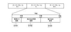
図4は、スーパーフレームの構造の一例を示す図である。本実施形態にかかる無線給電システムは、図4に示すようなスーパーフレームを1単位とし、このスーパーフレームを繰り返すことにより、送電装置10から受電装置20への送電を実現する。
1つのスーパーフレームは、S101(関連付け期間)、S102(電力伝送準備期間)及びS103(電力伝送期間)を含んでいる。なお、それぞれの期間は可変である。
S101において、送電装置10は、受電装置20へ受電要求の有無を確認する。受電装置20が受電を要求する場合には、処理はS102へ移行する。なお、S101からS102へ移行する期間も可変である。FIG. 4 is a diagram illustrating an example of a superframe structure. The wireless power supply system according to the present embodiment realizes power transmission from the
One superframe includes S101 (association period), S102 (power transmission preparation period), and S103 (power transmission period). Each period is variable.
In step S <b> 101, the
S102において、受電装置20は、送電装置10のデータリクエストによるフレームのレスポンスやアクノリッジを送信することができる。なお、それぞれのレスポンスフレームの長さやアクノリッジフレームの長さは可変である。S102が終了すると、処理はS103へ移行する。なお、S102からS103へ移行する期間も可変である。
S103において、送電装置10は、受電装置20へ電力を伝送する。S103において、受電装置20は、送電装置10からのリクエストフレームがなくても、フレームを送電装置10へ送信することができる。In step S <b> 102, the
In S <b> 103, the
図5は、パケットのフレームフォーマットの構造の一例を示す図である。無線給電システムは、スーパーフレーム内において、図5に示すパケットを用いて、無線給電のためのデータ通信を実現する。パケットは、フレームヘッダー310及びフレームボディ320を含む。
フレームヘッダー310は、データ転送時の宛先等を示すものである。フレームヘッダー310は、ID311、フレームコントロール312、発信元アドレス313、行先アドレス314及びシーケンスナンバー315を含む。ID311は、無線給電システムでデータ通信を行うときに使われるIDである。FIG. 5 is a diagram illustrating an example of a frame format structure of a packet. The wireless power supply system implements data communication for wireless power supply using the packet shown in FIG. 5 in the superframe. The packet includes a
The
フレームコントロール312は、受電装置20のデータ交換のための情報である。フレームコントロール312は、電力管理3120を含む。電力管理3120は、受電装置20の電力の必要性を確認するデータ、すなわち受電装置20が電力を要求するか否かを示すデータである。発信元アドレス313は、データ転送時における発信元のアドレスである。行先アドレス314は、データ転送時における行先のアドレスである。シーケンスナンバー315は、フレームの番号である。 The
フレームボディ320は、データ転送時のデータ本体の情報である。フレームボディ320は、ペイロード321及びフレームチェックシーケンス322を含む。ペイロード321は、データ本体である。例えば、デバイスID3210がペイロード321に割り当てられる。フレームチェックシーケンス322は、ペイロード321のエラーチェックを行うデータである。 The
図6は、無線給電システムにおける給電処理を示すシーケンス図である。給電処理において、送電装置10と受電装置20との間で、スーパーフレームを用いたデータの送受信が行われる。
S201において、送電装置10は、受電装置20に対してデバイスIDを要求する。このとき、図5に示すフレームフォーマットのID311が利用される。これに対し、S202において、送電装置10は、受電装置20からデバイスIDを受信する。このとき、図5に示すフレームフォーマットのデバイスID3210が利用される。FIG. 6 is a sequence diagram illustrating power supply processing in the wireless power supply system. In the power supply process, data transmission / reception is performed between the
In step S <b> 201, the
次に、S203において、送電装置10は、受電装置20に電力要求の有無を確認する電力要求確認を送信する。このときは、フレームフォーマットの電力管理3120が利用される。次に、S204において、受電装置20は、受電を要求する場合には、送電装置10へ電力要求通知を送信する。また、S204において、受電装置20は、電力を要求しない場合には、送電装置10へ電力不要通知を送信する。このとき、図5に示すフレームフォーマットの電力管理3120が利用される。
次に、S205において、送電装置10は、電力伝送の準備を行う。次に、S206において、送電装置10は、受電装置20へ電力伝送を行う。S206における電力伝送後は、S207において、受電装置20は、適宜電力伝送状態を送電装置10に送信する。なお、S206における電力伝送後は、受電装置20は、送電装置10からのリクエストフレームがなくても送電装置10に情報を送信することができる。Next, in S <b> 203, the
Next, in S205, the
なお、本実施形態にかかる無線給電システムにおいては、受電装置20は、S207において、受電装置20は、送電装置10からの電力伝送の開始を検出した場合に、電力伝送開始通知を送電装置10に送信する。また、受電装置20は、電力伝送の開始を検出した後は、電力伝送の継続中において、定期的に受電状態であることを示す受電通知を送電装置10に送信する。また、受電装置20は、バッテリー236がフル充電になったことを検出すると、送電装置10へ電力伝送終了通知を送信する。なお、S207においては、図5に示すフレームフォーマットの電力管理3120が利用される。
なお、詳細については後述するが、本実施形態にかかる送電装置10は、受電装置20に電力伝送する電力レベルを、S207における受電装置20からの電力伝送状態により変動させる。In the wireless power feeding system according to the present embodiment, the
In addition, although mentioned later for details, the
図7は、電力伝送期間における受電装置20による電力伝送処理を示すフローチャートである。S701において、CPU211は、無線受信部230を介して、送電装置10からのデバイスID要求を受け付ける。CPU211は、送電装置10からのデバイスID要求を受け取ると(S701でYes)、S702において、無線送信部220を介して、送電装置10に自身のデバイスIDを送信する。
次に、S703において、CPU211は、無線送信部220を介して、電力を要求する場合には(S703でYes)、無線送信部220を介して、送電装置10に電力要求通知を送信する(S704)。一方、S703において、CPU211は、電力を要求しない場合には(S703でNo)、無線送信部220を介して、送電装置10に電力不要通知を送信し(S720)、処理を終了する。FIG. 7 is a flowchart illustrating power transmission processing by the
Next, in S703, when the
S705において、CPU211は、無線受信部230の検出信号237に基づいて、送電装置10からの受電の有無を検出する。S705において、CPU211は、送電装置10からの電力伝送を検出しない場合(S705でNo)、定期的にS705の処理を繰り返す。S705において、CPU211は、受電を検出すると(S705でYes)、無線送信部220を介して、送電装置10に電力伝送開始通知を送信する(S706)。ここで、電力伝送開始通知は、受電装置20が送電装置10から受電したことを示す受電通知の一例である。また、S706の処理は、受電通知送信処理の一例である。
例えば、受電装置20が給電エリア30内に存在するとする。この場合には、受電装置20は、送電装置10からの電力供給を受けることができる。したがって、この場合には、S705において、CPU211は、受電を検出することができる。一方で、受電装置20が給電エリア30の外側に存在するとする。この場合には、受電装置20は、送電装置10からの電力供給を受けることができない。したがって、この場合には、S705において、CPU211は、受電を検出することができない。In step S <b> 705, the
For example, it is assumed that the
S707において、CPU211は、バッテリー236の残量を確認する。S707において、CPU211は、バッテリー236がフルでないと判断すると(S707でNo)、処理をS708へ進める。S708において、CPU211は、前回の通知から一定時間が経過したか否かを判断する。ここで、一定時間は、受電装置20に予め設定されているものとする。また、前回の通知とは、S706における電力伝送開始通知又は後述するS710における受電継続通知の何れかの通知とする。
一定時間が経過している場合には(S708でYes)、CPU211は、送電装置10からの受電の有無を検出する(S709)。S709において、受電を検出した場合には、CPU211は、処理をS710へ進める。S710において、CPU211は、無線送信部220を介して、受電継続通知を送電装置10に送信する。ここで、受電継続通知は、受電を継続していることを通知するための情報であり、受電通知の一例である。また、S710の処理は、受電通知送信処理の一例である。In step S <b> 707, the
When the predetermined time has elapsed (Yes in S708), the
受電装置20は、S705において給電エリア30内に存在していた場合であっても、S705の処理の後、給電エリア30の外側に移動する場合がある。このような場合には、送電装置10からの給電中であるにも関わらず、受電装置20においては、送電装置10からの電力の供給を受けることができなくなる。
そこで、本実施形態の無線給電システムにおいては、受電装置20が継続して受電していることの送電装置10による確認を可能とすべく、受電装置20は、S708〜S710の処理により、定期的に継続受電通知を送電装置10に送信する。Even if the
Therefore, in the wireless power feeding system of the present embodiment, the
S708において前回の通知から一定時間が経過していない場合(S708でNo)、又はS709において受電を検出しない場合(S709でNo)には、CPU211は、処理をS707へ進める。S707において、CPU211は、バッテリー236がフルになるのを検出すると(S707でYes)、無線送信部220を介して、送電装置10に電力伝送終了通知を送信し(S711)、電力伝送処理が終了する。
このように、受電装置20は、送電装置10からの受電を検出した場合には、送電装置10に対して、受電していることを通知することができる。If the predetermined time has not elapsed since the previous notification in S708 (No in S708), or if no power reception is detected in S709 (No in S709), the
As described above, when receiving power from the
図8は、電力伝送期間における送電装置10による電力伝送処理を示すフローチャートである。S801において、CPU111は、無線送信部120を介して、受電装置20にデバイスID要求を送信する。S802において、CPU111は、無線受信部130を介して、受電装置20からデバイスIDを受信すると(S802でYes)、無線送信部120を介して、受電装置20に電力要求確認を送信する(S803)。
S804において、CPU111は、無線受信部130を介して、受電装置20から、受電を要求することを示す電力要求通知を受信すると(S804でYes)、電力伝送の準備を行う(S805)。S804において、受電装置20から電力不要通知を受信した場合には(S804でNo)、CPU111は、電力伝送処理を終了する。FIG. 8 is a flowchart illustrating power transmission processing by the
In S804, when the
S806において、CPU111は、無線送信部120の送電電力値を第1の電力である低電力レベルに決定する(電力決定処理)。そして、CPU111は、低電力レベルでの無線送信部120による送電を制御する(送電制御処理)。このとき、無線送信部120は、CPU111の制御の下、送電を行う(送電処理)。
S807において、CPU111は、無線受信部130を介して、受電装置20から電力伝送開始通知を受信すると(S807でYes)、CPU111は、処理をS808へ進める。電力伝送開始通知は、受電通知の一例であり、S807において、電力伝送開始通知を受信する処理は、受電通知受信処理の一例である。In step S <b> 806, the
In S807, when the
S808において、CPU111は、無線送信部120の送電電力値を、第1の電力である低電力レベルに比べて高い第2の電力である通常電力レベルに決定する(電力決定処理)。そして、CPU111は、通常電力レベルでの無線送信部120による送電を制御し(送電制御処理)、無線送信部120は、送電を行う(送電処理)。
なお、送電装置10が受電装置20から電力伝送開始通知を受信するのは、受電装置20が給電エリア内に存在する場合に限られる。送電装置10は、上記処理により、受電装置20が給電エリア30内に存在することを確認するまでは、低電力レベルでの電力供給を行う。しがって、送電装置10による、受電装置20が受電できない状況における不要な電力伝送を抑制することができる。In step S808, the
The
なお、低電力レベル及び通常電力レベルの値は、それぞれ予め送電装置10に設定されているものとする。低電力レベルの値は、低ければ低い程、不要な電力伝送を抑制する効果が大きくなる。しかしながら、低電力レベルの値が低すぎる場合には、受電装置20において、受電を検出できなくなってしまう。したがって、低電力レベルの値は、受電装置20の検出回路238が受電を検出可能な程度の値であることが好ましい。
図9は、送電装置10による送電電力の電力レベル(送電設定値)の切り替えタイミングを示す図である。図9において、横軸及び縦軸は、それぞれ時間及び送電電力の電力レベルを示している。図9に示すように送電装置10のCPU111は、電力伝送準備期間が完了すると、低電力レベルでの電力伝送を開始する。そして、CPU111は、電力伝送開始通知を受信すると、送電設定値を低電力レベルから通常電力レベルに切り替え、通常電力レベルでの電力伝送を開始する。Note that the values of the low power level and the normal power level are set in the
FIG. 9 is a diagram illustrating the switching timing of the power level (transmission set value) of the transmission power by the
図8に戻り、S809において、CPU111は、無線受信部130を介して、受電装置20から電力伝送終了通知を受信した場合(S809でYes)、CPU111は、無線送信部120からの受電装置20への電力伝送を停止する(S814)。
一方で、S809において、CPU111は、電力伝送終了通知を受信しない場合には(S809でNo)、処理をS810へ進める。S810において、CPU111は、前回の通知受信から一定時間内に受信継続通知を受信したか否かを確認する。ここで、一定時間は、送電装置10に予め設定されているものとする。なお、この一定時間は、受電装置20において、図7に示すS708にいて考慮する一定時間に基づいて決定されるのが好ましい。また、前回の通知受信とは、S810において確認する受電継続通知である。Returning to FIG. 8, in S809, when the
On the other hand, in S809, when the
S810において、前回の通知受信から一定時間内において受電継続通知を受信した場合には(S810でYes)、CPU111は、処理をS809へ進める。これにより、送電装置10は、電力伝送終了通知を受信するまで送電を継続する。S810において、前回の通知受信から一定時間内において受電継続通知を受信しない場合には(S810でNo)、CPU111は、処理をS811へ進める。S811において、CPU111は、無線送信部120の送電電力値を通常電力レベルから低電力レベルに切り替える。
このように、CPU111は、低電力レベルの電力の送電中において、一定時間の間受電継続通知を受信しない場合には、送電電力値を低電力レベルに変更する。なお、このとき、無線送信部120は、低電力レベルでの送電を行う。
次に、S812において、CPU111は、受電継続通知を受信した場合には(S812でYes)、処理をS808へ進める。S812において、CPU111は、受電継続通知を受信しない場合には(S812でNo)、処理をS813へ進める。S813において、CPU111は、電力伝送終了通知を受信した場合には(S813でYes)、処理をS814へ進める。一方、S813において、電力伝送終了通知を受信しない場合には(S813でNo)、処理をS812へ進める。In S810, when the power reception continuation notification is received within a predetermined time from the previous notification reception (Yes in S810), the
As described above, the
Next, in S812, when the
このように、送電装置10は、受電装置20への送電を開始した後においても、定期的に受電継続通知を受信することした。これにより、送電装置10は、受電継続通知を受信しない場合に、受電装置20が給電エリア30の外側に移動したことを検知することができる。この場合において、送電装置10は、受電装置20への電力伝送の電力値を小さい値に変更するので、不要な電力伝送を抑制することができる。
以上のように、本実施の形態にかかる送電装置10は、受電装置20が給電エリア30内に存在する場合に通常電力レベルの給電を行う一方、受電装置20が給電エリア30の外側に存在する場合には低電力レベルの給電を行う。これにより、無線給電システムにおいては、無線による給電において、送電装置から受電装置への不要な電力伝送を抑制することができる。Thus, even after power transmission to the
As described above, the
<第1の変更例>
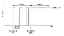
次に、無線給電システムの第1の変更例について説明する。図10は、第1の変更例にかかる送電装置10による電力伝送のタイミングチャートを示す図である。実施形態にかかる無線給電システムにおいては、送電装置10の無線送信部120は、給電エリア30の外側の受電装置20に対し、低電力レベルの送電を行うこととしたが、これに限定されるものではない。例えば、無線送信部120は、給電エリア30の外側に存在する受電装置20に対し、通常電力レベルの送電を間欠的に行うこととしてもよい。
具体的には、CPU111は、S808において、無線送信部120の送電電力値を、通常電力レベルに決定する。そして、CPU111は、間欠時間Tにおいて送電を停止することにより、無線送信部120に所定時間おきに間欠的に送電させる(送電制御処理)。ここで、間欠時間Tは、送電装置10に予め設定されているものとする。
図10に示すように、送電装置10のCPU111は、電力伝送準備が完了すると、通常電力レベルでの間欠伝送を開始する。そして、CPU111は、電力伝送開始通知を受信すると、通常電力レベルでの継続的な電力供給である継続伝送を開始する。<First modification>
Next, a first modification of the wireless power feeding system will be described. FIG. 10 is a diagram illustrating a timing chart of power transmission by the
Specifically, in step S808, the
As illustrated in FIG. 10, when the power transmission preparation is completed, the
このように、第1の変更例にかかる送電装置10は、受電装置20が給電エリア30の外側に存在する場合には、電力伝送を間欠的に行うことにより、電力伝送時間を短縮する。これにより、本例における無線給電システムにおいては、通常電力レベルを維持しつつ、不要な電力伝送を抑制することができる。
なお、本例においては、間欠時間Tが長くなる程、不要な電力伝送を抑制する効果が大きくなる。しかしながら、間欠時間Tが長くなると、受電装置20が給電エリア30内への移動タイミングと、送電装置10が電力伝送開始通知の受信タイミングのタイムラグが大きくなる。そこで、受電装置20が給電エリア30内に移動したことの検知後速やかに継続伝送を開始可能な時間間隔とするのが好ましい。As described above, the
In this example, the longer the intermittent time T, the greater the effect of suppressing unnecessary power transmission. However, when the intermittent time T becomes longer, the time lag between the timing at which the
<第2の変更例>
次に、第2の変更例について説明する。本実施の形態にかかる無線給電システムにおいては、送電装置10は、受電装置20から電力要求を受信した場合には、電力伝送開始通知を受信するまで、低電力レベルの電力伝送を継続する(図8のS807、S808)。このため、送電装置10は、受電装置20が給電エリア30内に移動するまで、他の受電装置20への送電を行うことができない。
これに対し、本変更例にかかる無線給電システムにおいては、送電装置10は、S808及びS811において、低電力レベルの電力伝送を継続する時間に対し、時間閾値を設定してもよい。ここで、時間閾値は、送電装置10に予め設定されているものとする。
この場合には、送電装置10のCPU111は、低電力レベルでの電力伝送を開始すると、低電力レベルでの電力伝送の送電時間を計測する。そして、送電時間が時間閾値以上となった場合には、CPU111は、無線送信部120に対し、受電装置20への電力伝送の停止を指示する。<Second modification>
Next, a second modification example will be described. In the wireless power feeding system according to the present embodiment, when the
On the other hand, in the wireless power feeding system according to the present modification, the
In this case, when the power transmission at the low power level is started, the
このように、第2の変更例にかかる無線給電システムにおいては、送電装置10は、低電力レベルでの電力伝送が時間閾値以上の間行われた場合に、受電装置20への電力伝送を停止する。これにより、送電装置10から他の受電装置20への電力伝送を可能とすることができる。
なお、送電装置10は、受電装置20への電力伝送を停止した場合には、停止した旨を受電装置20に通知することとする。そして、受電装置20は、この通知を受けた場合に、電力伝送処理(図7)を終了する。これにより、受電装置20は、再度電力伝送処理(図7)を開始することができる。Thus, in the wireless power feeding system according to the second modification, the
When the power transmission to the
<その他の実施形態>
また、本発明は、以下の処理を実行することによっても実現される。即ち、上述した実施形態の機能を実現するソフトウェア(プログラム)を、ネットワーク又は各種記憶媒体を介してシステム或いは装置に供給する。そして、そのシステム或いは装置のコンピュータ(又はCPUやMPU等)がプログラムを読み出して実行する処理である。<Other embodiments>
The present invention can also be realized by executing the following processing. That is, software (program) that realizes the functions of the above-described embodiments is supplied to a system or apparatus via a network or various storage media. Then, the computer (or CPU, MPU, etc.) of the system or apparatus reads and executes the program.
以上、上述した各実施形態によれば、無線による給電において、送電装置から受電装置への不要な電力伝送を抑制することができる。 As described above, according to each of the above-described embodiments, unnecessary power transmission from the power transmission device to the power reception device can be suppressed in wireless power feeding.
以上、本発明の好ましい実施形態について詳述したが、本発明は係る特定の実施形態に限定されるものではなく、特許請求の範囲に記載された本発明の要旨の範囲内において、種々の変形・変更が可能である。 The preferred embodiments of the present invention have been described in detail above, but the present invention is not limited to such specific embodiments, and various modifications can be made within the scope of the gist of the present invention described in the claims.・ Change is possible.
Claims (8)
Translated fromJapanese前記受電通知を受信した場合に、前記受電装置へ送電する送電電力値を第1の電力に決定し、前記受電通知を受信しない場合に、前記受電装置への送電電力値を第1の電力に比べて小さい第2の電力に決定する電力決定手段と、
前記電力決定手段により決定された電力を、無線により前記受電装置に送電する送電手段と
を有することを特徴とする送電装置。A power reception notification receiving means for receiving a power reception notification indicating that the power reception device has received power from the power reception device;
When the power reception notification is received, the transmission power value to be transmitted to the power reception device is determined as the first power, and when the power reception notification is not received, the transmission power value to the power reception device is set to the first power. A power determining means for determining a second power smaller than the second power;
A power transmission device comprising: a power transmission unit configured to wirelessly transmit the power determined by the power determination unit to the power receiving device.
前記電力決定手段は、前記送電手段による前記第1の電力の送電中において、一定時間の間、前記受電通知を受信しない場合に、前記送電電力値を前記第2の電力に変更することを特徴とする請求項1乃至3何れか1項に記載の送電装置。The power reception notification receiving means periodically receives the power reception notification from the power receiving device,
The power determination unit changes the transmission power value to the second power when the power reception unit does not receive the power reception notification for a certain time during the transmission of the first power by the power transmission unit. The power transmission device according to any one of claims 1 to 3.
前記受電装置は、
前記送電装置から受電する受電手段と、
前記受電手段が受電した場合に、受電通知を前記送電装置に送信する受電通知送信手段と
を有し、
前記送電装置は、
前記受電通知を、前記受電装置から受信する受電通知受信手段と、
前記受電通知を受信した場合に、前記受電装置へ送電する送電電力値を第1の電力に決定し、前記受電通知を受信しない場合に、前記受電装置への送電電力値を第1の電力に比べて小さい第2の電力に決定する電力決定手段と、
前記電力決定手段により決定された電力を、無線により前記受電装置に送電する送電手段と
を有することを特徴とする送電システム。A power transmission system comprising: a power transmission device that supplies power wirelessly; and a power reception device that receives power from the power transmission device,
The power receiving device is:
Power receiving means for receiving power from the power transmission device;
A power reception notification transmission means for transmitting a power reception notification to the power transmission device when the power reception means receives power;
The power transmission device is:
Power reception notification receiving means for receiving the power reception notification from the power reception device;
When the power reception notification is received, the transmission power value to be transmitted to the power reception device is determined as the first power, and when the power reception notification is not received, the transmission power value to the power reception device is set to the first power. A power determining means for determining a second power smaller than the second power;
A power transmission system comprising: a power transmission unit configured to wirelessly transmit the power determined by the power determination unit to the power receiving device.
受電装置が受電したことを示す受電通知を、前記受電装置から受信する受電通知受信ステップと、
前記受電通知を受信した場合に、前記受電装置へ送電する送電電力値を第1の電力に決定し、前記受電通知を受信しない場合に、前記受電装置への送電電力値を第1の電力に比べて小さい第2の電力に決定する電力決定ステップと、
前記電力決定ステップにおいて決定された電力を、無線により前記受電装置に送電する送電ステップと
を含むことを特徴とする送電方法。A power transmission method executed by a power transmission device,
A power reception notification receiving step for receiving a power reception notification indicating that the power reception device has received power from the power reception device;
When the power reception notification is received, the transmission power value to be transmitted to the power reception device is determined as the first power, and when the power reception notification is not received, the transmission power value to the power reception device is set to the first power. A power determining step for determining a second power that is smaller than the second power;
A power transmission method comprising: a power transmission step of wirelessly transmitting the power determined in the power determination step to the power receiving device.
前記受電装置が前記受電装置から受電する受電ステップと、
前記受電ステップにおいて前記受電装置が受電した場合に、前記受電装置が受電通知を前記送電装置に送信する受電通知送信ステップと、
前記送電装置が、前記受電通知を、前記受電装置から受信する受電通知受信ステップと、
前記受電装置が、前記受電通知を受信した場合に、前記受電装置へ送電する送電電力値を第1の電力に決定し、前記受電通知を受信しない場合に、前記受電装置への送電電力値を第1の電力に比べて小さい第2の電力に決定する電力決定ステップと、
前記受電装置が、前記電力決定ステップにおいて決定された電力を、無線により前記受電装置に送電する送電ステップと
を含むことを特徴とする送電方法。A power transmission method executed by a power transmission system including a power transmission device that wirelessly supplies power and a power reception device that receives power from the power transmission device,
A power receiving step in which the power receiving device receives power from the power receiving device;
A power reception notification transmitting step in which the power reception device transmits a power reception notification to the power transmission device when the power reception device receives power in the power reception step;
The power transmission device receives the power reception notification from the power reception device;
When the power reception device receives the power reception notification, the power transmission power value to be transmitted to the power reception device is determined as the first power, and when the power reception notification is not received, the power transmission power value to the power reception device is determined. A power determining step for determining a second power that is smaller than the first power;
The power receiving method includes: a power transmission step in which the power receiving device transmits the power determined in the power determining step to the power receiving device wirelessly.
受電装置が受電したことを示す受電通知を、前記受電装置から受信する受電通知受信手段と、
前記受電通知を受信した場合に、前記受電装置へ送電する送電電力値を第1の電力に決定し、前記受電通知を受信しない場合に、前記受電装置への送電電力値を第1の電力に比べて小さい第2の電力に決定する電力決定手段と
して機能させるためのプログラム。Computer
A power reception notification receiving means for receiving a power reception notification indicating that the power reception device has received power from the power reception device;
When the power reception notification is received, the transmission power value to be transmitted to the power reception device is determined as the first power, and when the power reception notification is not received, the transmission power value to the power reception device is set to the first power. The program for functioning as a power determination means which determines 2nd electric power smaller compared with.
Priority Applications (2)
| Application Number | Priority Date | Filing Date | Title |
|---|---|---|---|
| JP2013022377AJP6100014B2 (en) | 2013-02-07 | 2013-02-07 | Power transmission device, power transmission device control method, and program |
| US14/174,682US20140222236A1 (en) | 2013-02-07 | 2014-02-06 | Power transmission device, power transmission system, power transmission method, and program |
Applications Claiming Priority (1)
| Application Number | Priority Date | Filing Date | Title |
|---|---|---|---|
| JP2013022377AJP6100014B2 (en) | 2013-02-07 | 2013-02-07 | Power transmission device, power transmission device control method, and program |
Publications (3)
| Publication Number | Publication Date |
|---|---|
| JP2014155304Atrue JP2014155304A (en) | 2014-08-25 |
| JP2014155304A5 JP2014155304A5 (en) | 2016-03-24 |
| JP6100014B2 JP6100014B2 (en) | 2017-03-22 |
Family
ID=51259947
Family Applications (1)
| Application Number | Title | Priority Date | Filing Date |
|---|---|---|---|
| JP2013022377AExpired - Fee RelatedJP6100014B2 (en) | 2013-02-07 | 2013-02-07 | Power transmission device, power transmission device control method, and program |
Country Status (2)
| Country | Link |
|---|---|
| US (1) | US20140222236A1 (en) |
| JP (1) | JP6100014B2 (en) |
Cited By (1)
| Publication number | Priority date | Publication date | Assignee | Title |
|---|---|---|---|---|
| WO2017064955A1 (en)* | 2015-10-15 | 2017-04-20 | ローム株式会社 | Power transmission device and noncontact power supply system |
Citations (3)
| Publication number | Priority date | Publication date | Assignee | Title |
|---|---|---|---|---|
| WO2012111127A1 (en)* | 2011-02-17 | 2012-08-23 | パイオニア株式会社 | Charge control device and method, charging system, association method, and computer program |
| JP2012200056A (en)* | 2011-03-18 | 2012-10-18 | Fujitsu Ten Ltd | Power reception device, power transmission device, and control method |
| JP2013240130A (en)* | 2012-05-11 | 2013-11-28 | Toyota Motor Corp | Power transmission unit, power transmission device, power reception device, vehicle and contactless power supply system |
Family Cites Families (5)
| Publication number | Priority date | Publication date | Assignee | Title |
|---|---|---|---|---|
| US8497658B2 (en)* | 2009-01-22 | 2013-07-30 | Qualcomm Incorporated | Adaptive power control for wireless charging of devices |
| US9035601B2 (en)* | 2011-05-05 | 2015-05-19 | Samsung Electro-Mechanics | Wireless power transfer system and methods |
| US20130020988A1 (en)* | 2011-07-21 | 2013-01-24 | Samsung Electro-Mechanics Company, Ltd. | Multi-Frequency Wireless Systems and Methods |
| KR101667318B1 (en)* | 2011-12-27 | 2016-10-18 | 쥬코쿠 덴료쿠 가부시키 가이샤 | Wireless power transfer system, transmission device, and controlling method of wireless power transfer system |
| US20140191712A1 (en)* | 2013-01-10 | 2014-07-10 | Adam D. Rea | Power delivery including out-of-band communication |
- 2013
- 2013-02-07JPJP2013022377Apatent/JP6100014B2/ennot_activeExpired - Fee Related
- 2014
- 2014-02-06USUS14/174,682patent/US20140222236A1/ennot_activeAbandoned
Patent Citations (3)
| Publication number | Priority date | Publication date | Assignee | Title |
|---|---|---|---|---|
| WO2012111127A1 (en)* | 2011-02-17 | 2012-08-23 | パイオニア株式会社 | Charge control device and method, charging system, association method, and computer program |
| JP2012200056A (en)* | 2011-03-18 | 2012-10-18 | Fujitsu Ten Ltd | Power reception device, power transmission device, and control method |
| JP2013240130A (en)* | 2012-05-11 | 2013-11-28 | Toyota Motor Corp | Power transmission unit, power transmission device, power reception device, vehicle and contactless power supply system |
Cited By (3)
| Publication number | Priority date | Publication date | Assignee | Title |
|---|---|---|---|---|
| WO2017064955A1 (en)* | 2015-10-15 | 2017-04-20 | ローム株式会社 | Power transmission device and noncontact power supply system |
| JP2017077093A (en)* | 2015-10-15 | 2017-04-20 | ローム株式会社 | Power transmission device and non-contact power feeding system |
| US10432029B2 (en) | 2015-10-15 | 2019-10-01 | Rohm Co., Ltd. | Power transmission device and non-contact power feeding system |
Also Published As
| Publication number | Publication date |
|---|---|
| US20140222236A1 (en) | 2014-08-07 |
| JP6100014B2 (en) | 2017-03-22 |
Similar Documents
| Publication | Publication Date | Title |
|---|---|---|
| JP6164914B2 (en) | Power supply apparatus, control method, and program | |
| KR101889868B1 (en) | Apparatus and method for wireless energy transmission based on frame | |
| JP6100011B2 (en) | Power supply apparatus, power supply method, and program | |
| JP6278687B2 (en) | Electronic device, method and program | |
| US9831029B2 (en) | Power transmission device, power transmission method, and storage medium | |
| JP6545304B2 (en) | Power transmission device, power transmission method and program | |
| KR101900313B1 (en) | Electronic device | |
| JP6425528B2 (en) | Power transmission device, control method of power transmission device, program | |
| JP2014204612A (en) | Power feeding device, power feeding method and program | |
| JP6168829B2 (en) | Power supply apparatus, power supply method, and program | |
| JP6410476B2 (en) | ELECTRONIC DEVICE, ITS CONTROL METHOD, PROGRAM, AND POWER SUPPLY DEVICE | |
| US9653925B2 (en) | Power transmission device, power transmission method, and storage medium | |
| US9543791B2 (en) | Power transmission apparatus, power transmission method, and storage medium | |
| JP2015130748A (en) | Power receiving device, power transmitting / receiving device, power transmitting device, wireless power feeding system, information processing method, and program | |
| JP2013219475A (en) | Radio access point with wireless power supply function and radio communication terminal | |
| JP6100014B2 (en) | Power transmission device, power transmission device control method, and program | |
| JP6381209B2 (en) | Power transmission device, control method, and program | |
| JP2015042050A (en) | Wireless power feeding system, power receiving device, power transmitting device, control method thereof, and program | |
| JP6168869B2 (en) | Power supply device | |
| JP6222986B2 (en) | Electronic device, control method, program, and recording medium | |
| JP2015133844A (en) | Power transmission device, power receiving device, information processing method, and program | |
| JP6452468B2 (en) | Power supply apparatus, control method, and program | |
| JP6632282B2 (en) | Power receiving device, power receiving device control method, and program | |
| JP2015089154A (en) | Control device, power transmission device, power transmission system, and control method | |
| JP6743234B2 (en) | Power receiving device, power transmitting device, power receiving device control method, power transmitting device control method, and program |
Legal Events
| Date | Code | Title | Description |
|---|---|---|---|
| A521 | Request for written amendment filed | Free format text:JAPANESE INTERMEDIATE CODE: A523 Effective date:20160204 | |
| A621 | Written request for application examination | Free format text:JAPANESE INTERMEDIATE CODE: A621 Effective date:20160204 | |
| A977 | Report on retrieval | Free format text:JAPANESE INTERMEDIATE CODE: A971007 Effective date:20161017 | |
| A131 | Notification of reasons for refusal | Free format text:JAPANESE INTERMEDIATE CODE: A131 Effective date:20161025 | |
| A521 | Request for written amendment filed | Free format text:JAPANESE INTERMEDIATE CODE: A523 Effective date:20161221 | |
| TRDD | Decision of grant or rejection written | ||
| A01 | Written decision to grant a patent or to grant a registration (utility model) | Free format text:JAPANESE INTERMEDIATE CODE: A01 Effective date:20170124 | |
| A61 | First payment of annual fees (during grant procedure) | Free format text:JAPANESE INTERMEDIATE CODE: A61 Effective date:20170222 | |
| R151 | Written notification of patent or utility model registration | Ref document number:6100014 Country of ref document:JP Free format text:JAPANESE INTERMEDIATE CODE: R151 | |
| LAPS | Cancellation because of no payment of annual fees |