JP2014153956A - Electronic apparatus - Google Patents
Electronic apparatusDownload PDFInfo
- Publication number
- JP2014153956A JP2014153956AJP2013023817AJP2013023817AJP2014153956AJP 2014153956 AJP2014153956 AJP 2014153956AJP 2013023817 AJP2013023817 AJP 2013023817AJP 2013023817 AJP2013023817 AJP 2013023817AJP 2014153956 AJP2014153956 AJP 2014153956A
- Authority
- JP
- Japan
- Prior art keywords
- unit
- display
- detection unit
- electronic device
- icon
- Prior art date
- Legal status (The legal status is an assumption and is not a legal conclusion. Google has not performed a legal analysis and makes no representation as to the accuracy of the status listed.)
- Pending
Links
Images


Landscapes
- Position Input By Displaying (AREA)
- User Interface Of Digital Computer (AREA)
- Telephone Function (AREA)
- Input From Keyboards Or The Like (AREA)
Abstract
Translated fromJapaneseDescription
Translated fromJapanese本発明は、電子機器に関する。 The present invention relates to an electronic device.
携帯電子機器、例えば、多機能携帯電話機やタブレット端末装置等には、画像を表示する表示装置とユーザによる操作入力を受け付ける位置入力装置(タッチセンサ)とを組み合わせたタッチパネルを備えたものがある。表示装置の画面には、キーやアイコン等の画面部品が表示されることがある。ユーザは、画面部品が表示されたタッチパネルの位置に、例えば自己の指等の操作物を接触させることで、キー入力を行い、またアイコン等を指示してインタフェースを操作することができる。
表示される画面部品の位置によっては、ユーザにとって片手で機器を操作することが困難なことがあった。例えば、ユーザの手の大きさや機器の大きさによって、画面部品とは異なる位置に自己の指を接触させることによる誤操作や、機器の持ち替えを強いられることがあった。
そこで、特許文献1に記載の携帯端末は、タッチパネルを有する携帯端末であって、タッチパネル上にキーやアイコン等の項目を配置する配置手段を有し、タッチパネル上またはタッチパネル周辺に、操作するユーザの指の位置を感知するセンサをさらに有する。配置手段は、センサで感知した操作するユーザの指の位置によって、項目を指の位置近傍に配置する。Some portable electronic devices, for example, multi-function mobile phones and tablet terminal devices, include a touch panel that combines a display device that displays an image and a position input device (touch sensor) that receives an operation input by a user. Screen parts such as keys and icons may be displayed on the screen of the display device. The user can operate the interface by inputting a key by pointing an operation object such as his / her finger to the position of the touch panel on which the screen component is displayed, for example, and instructing an icon or the like.
Depending on the position of the displayed screen component, it may be difficult for the user to operate the device with one hand. For example, depending on the size of the user's hand or the size of the device, an erroneous operation by bringing his / her finger into contact with a position different from the screen component or a change of the device may be forced.
Therefore, the portable terminal described in
しかしながら、特許文献1に記載の携帯端末は、ユーザがタッチパネルの画面上の操作しやすい位置に指を置いたとき、センサによって指の位置が感知され、その位置付近にメニューアイコンを配置することがある。メニューアイコンを配置する処理は、長押し等の動作を用いてメニューアイコンを選択する動作との区別がなされる。この場合、ユーザが意図せずにタッチパネルの画面上に指を触れ続けると、指が触れた位置にメニューアイコンが配置されてしまい、操作性が損なわれることがある。
本発明は上記の点に鑑みてなされたものであり、操作性を向上した電子機器を提供する。However, when the user places a finger at a position on the touch panel screen where the user can easily operate the portable terminal described in
The present invention has been made in view of the above points, and provides an electronic apparatus with improved operability.
本発明は上記の課題を解決するためになされたものであり、本発明の一態様は、操作入力を受け付けた位置を検出する位置検出部と、前記位置検出部とは異なる位置への押圧による押圧値を検出する押圧検出部と、前記押圧検出部が検出した押圧値に基づいて予め定めた複数の動作モードのうちのいずれか用いるかを判定する動作判定部と、前記位置検出部が操作入力を受け付ける範囲と機能を示す画面部品を表示する表示部と、前記動作判定部が判定した動作モードに応じた配置で前記画面部品を前記表示部に表示させる表示制御部と、を備えることを特徴とする電子機器である。 The present invention has been made to solve the above-described problems, and one aspect of the present invention is based on a position detection unit that detects a position at which an operation input is received, and by pressing a position different from the position detection unit. A pressure detection unit that detects a pressure value, an operation determination unit that determines which one of a plurality of predetermined operation modes to use based on the pressure value detected by the pressure detection unit, and the position detection unit that is operated A display unit that displays a screen component indicating a range and function that accepts an input; and a display control unit that displays the screen component on the display unit in an arrangement according to the operation mode determined by the operation determination unit. It is a featured electronic device.
本発明によれば、電子機器において操作性が向上する。 According to the present invention, operability is improved in an electronic device.
(第1の実施形態)
以下、図面を参照しながら本発明の第1の実施形態について説明する。
図1は、本実施形態に係る電子機器1の外観構成を示す表面図である。
電子機器1は、押圧センサ(押圧検出部)101、タッチセンサ(位置検出部)103及び筐体(収容部)105を含んで構成される。電子機器1は、例えば、多機能携帯電話機(いわゆるスマートフォンを含む)、タブレット端末装置、等である。
図1に示す例では、電子機器1は、一辺の長さ(高さ)が他の一辺の長さ(幅)よりも大きい縦長の長方形の形状を有する。本実施形態では、これには限られず電子機器1は、幅が高さよりも広い横長の長方形の形状を有していてもよい。図1では、X方向は電子機器1の幅の方向を示し、Y方向は電子機器1の高さの方向を示し、Z方向は電子機器1の厚みの方向を示す。以下の説明では、X方向、Y方向、Z方向を、それぞれ右、下、厚み、と呼ぶことがある。
電子機器1の大きさは、ユーザが携帯可能であれば、いかなる大きさであってもよい。一例として、電子機器1は、概ね人間の片手で把持できる程度の大きさを有する。その場合、電子機器1は、例えば、幅は55〜85mm、高さは100〜160mm、厚さは8mm〜20mmの範囲のいずれかの寸法を有する。厚さは、Z方向の辺の長さである。(First embodiment)
Hereinafter, a first embodiment of the present invention will be described with reference to the drawings.
FIG. 1 is a surface view showing an external configuration of an
The
In the example shown in FIG. 1, the
The
押圧センサ101は、操作物が自己に接触されることで加えられた押圧を検出し、検出した押圧値を示す押圧信号を生成する。押圧値は、押圧の大きさを示す値である。押圧センサ101は、例えば、加えられた押圧を電気信号に変換する圧電素子である。その場合、変換された電気信号の電圧等の信号値は、押圧値を示す。図1に示す例では、押圧センサ101は、一辺(長辺)の長さが他の辺の長さよりも大きい細長い形状を有し、いずれかの部位に加えられた押圧を検知する。押圧センサ101は、電子機器1の表面においてタッチセンサ103が占める領域外(外枠部)の右端に、その長辺が電子機器1の高さの方向に平行に配置される。これにより、ユーザが電子機器1を左右いずれかの手で把持する際に指や手のひら等で、外枠部の右端に加えられた押圧が検知される。
押圧センサ101は、生成した押圧信号を押圧検知部111(後述)に出力する。The
The
タッチセンサ103は、操作物(例えば、ユーザの指)が接触した位置を検出し、検出した位置を示す位置情報(タッチ情報)を生成し、生成した位置情報をタッチセンサ情報処理部114(後述)に出力する。タッチセンサ103は、例えば、静電容量式、抵抗膜式、赤外線式、等のいずれであってもよい。タッチセンサ103は、ほぼ長方形の平板の形状を有し、電子機器1の表面の大部分を覆うように配置される。タッチセンサ103は、操作物が接触した位置を検出するために、例えば静電容量センサを備える。タッチセンサ103は、画像を表示する表示部102(後述)と一体化してタッチパネルを構成する。タッチセンサ103が画像を表示する領域と表示部102が画像を表示する領域とは、同一であってもよい。
筐体105は、電子機器1の各構成部を収容し、押圧センサ101及びタッチセンサ103の位置を固定する。The
The
(電子機器の断面)
図2は、本実施形態に係る電子機器1の断面図である。
図2に示す断面図は、図1のAA’線を通過し、XY平面に垂直な断面を示す図である。図1のAA’線は、電子機器1の幅の方向に平行な線分であって、電子機器1の高さの方向の中点を通る線分である。図2では、X方向は電子機器1の幅の方向を示し、Z方向は電子機器1の厚みの方向を示す。
電子機器1は、押圧センサ101、タッチセンサ103及び筐体105の他、さらに表示部102及び保護パネル(押圧伝達部)104を含んで構成される。
表示部102は、タッチセンサ103の裏面に設けられ、表示制御部115(後述)から入力された画像信号に基づく画像を表示する。表示部102は、例えば、液晶表示パネル、有機EL表示パネル、等である。表示部102が表示する画像は、透明な部材からなるタッチセンサ103を透かして見ることができる。(Cross section of electronic equipment)
FIG. 2 is a cross-sectional view of the
The cross-sectional view shown in FIG. 2 is a view showing a cross section passing through the line AA ′ of FIG. 1 and perpendicular to the XY plane. A line AA ′ in FIG. 1 is a line segment parallel to the width direction of the
The
The
保護パネル104は、電子機器1の表面に配置され、少なくとも押圧センサ101及びタッチセンサ103の表面をそれぞれ覆うように配置されている。保護パネル104は、操作物と接触することによって、その表面に加えられた押圧を、裏面に接触している押圧センサ101、タッチセンサ103又はその両者に伝達する。保護パネル104に加えられた押圧のうち、表面から裏面への方向(Zの負方向)に伝達される成分が主であり、XY平面に平行に伝達される成分は比較的少ない。保護パネル104には、透明な部材(例えば、ポリエステル樹脂フィルム)が用いられ、表示部102が発する画像の光を透過する。そのため、タッチセンサ103が表示する画像は、保護パネル104の表面から視認可能であり、図1には保護パネル104を表示していない。なお、保護パネル104は、本実施形態では必須ではない。電子機器1によっては、保護パネル104を備えていなくてもよい。 The
(電子機器の内部構成)
次に、本実施形態に係る電子機器1の内部構成について説明する。
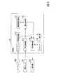
図3は、本実施形態に係る電子機器1の内部構成を示す概略ブロック図である。
電子機器1は、押圧センサ101、表示部102、タッチセンサ103及び制御部110を含んで構成される。制御部110は、押圧検知部(押圧入力部)111、動作判定部112、制御情報記憶部113、タッチセンサ情報処理部(位置入力部)114、表示制御部115及びアプリケーション実行部116を含んで構成される。(Internal configuration of electronic equipment)
Next, an internal configuration of the
FIG. 3 is a schematic block diagram showing the internal configuration of the
The
押圧検知部111は、押圧センサ101から入力された押圧信号を予め定めた時間間隔(例えば、20ms)毎に検知する。押圧検知部111は、検知した押圧信号を動作判定部112に出力する。押圧検知部111は、検知した押圧信号についてノイズ除去処理等の処理を行い、動作判定部112に出力してもよい。
動作判定部112は、制御情報記憶部113から制御情報として予め定めた押圧値の閾値と動作モード情報を読み出す。動作モード情報は、複数の動作モードのいずれかを示す情報である。動作モードは、例えば、自機(電子機器1)における画面部品の配置に係る処理の形態である。画面部品は、表示部102に表示される表示領域への操作入力をタッチセンサ103等のポインティングデバイスによって受け付け可能であることを示す画像である。画面部品は、UI(User Interface)部品、GUI(Graphic User Interface)コンポーネントとも呼ばれ、例えば、アイコン、ボタン、リンク、等がある。動作モードの具体例については後述する。The
The
動作判定部112は、押圧検知部111から入力された押圧信号が示す押圧値と、読み出した押圧値の閾値に基づいて複数の動作モードのいずれを用いるかを判定する。
動作判定部112は、例えば、押圧検知部111から入力された押圧信号が示す押圧値が、その閾値を越えたか否かを判定する。つまり、動作判定部112は、押圧値が、読み出した閾値よりも小さい状態から大きい状態に変化したか否かを判定する。押圧値が閾値よりも小さい状態が継続する場合や、押圧値が閾値よりも大きい状態が継続する場合には、閾値を越えていないと判定される。閾値を越えたと判定した場合には、動作判定部112は、複数の動作モードのうちいずれかの動作モードを用いるかを判定する。例えば、動作判定部112は、複数の動作モードのうち現在用いられている動作モードとは別個の動作モードを用いると判定する。ここで、動作判定部112は、予め定めた順序で巡回的(トグル順)に動作モードを選択してもよい。動作判定部112は、判定した動作モードを示す動作判定信号を生成し、生成した動作判定信号を表示制御部115に出力する。The
For example, the
制御情報記憶部113には、制御情報が予め記憶されている。制御情報は、上述のように、押圧値の閾値、複数の動作モードを含む情報である。
タッチセンサ情報処理部114は、タッチセンサ103から入力された位置情報を予め定めた時間間隔(例えば、20ms)毎に検知し、検知した位置情報を表示制御部115及びアプリケーション実行部116に出力する。Control information is stored in the control
The touch sensor
表示制御部115には、アプリケーション実行部116から入力された画像信号と、動作判定部112からの動作判定信号が入力される。表示制御部115は、画面部品を示す画像信号やアプリケーション実行部116から入力された画像信号を表示部102に出力する。画面部品は、例えば、アプリケーション実行部116が実行するアプリケーションソフトウェア(以下、アプリケーションともいう)を示す文字、記号、模様、又はそれらの組み合わせを表すアイコンが該当する。ここで、タッチセンサ情報処理部114から入力された位置情報が示す位置が、表示部102に表示されているアイコンのいずれかの範囲に含まれることがある。以下の説明では、この状態を、「アイコンが選択された」、と呼ぶことがある。表示制御部115は、タッチセンサ情報処理部114からの位置情報の入力が停止されたとき、そのアイコンに係るアプリケーションを起動させることを指示するアプリケーション起動信号を生成し、生成したアプリケーション起動信号をアプリケーション実行部116に出力する。これにより、ユーザがアイコンを選択している操作物(例えば、ユーザの指等)をタッチセンサ103から離したときに選択が確定し、例えば、そのアイコンに係るアプリケーションが起動する。 The
表示制御部115は、入力された動作判定信号が示す動作モードに応じた配置で画面部品を表示部102に表示させる位置を制御する。以下では、主に、動作モードの数が2個であり、2個の動作モードのうちの一方が動作モード1、他方が動作モード2であって、画面部品としてアイコンを表示部102に表示させる場合を例にとって説明する。
入力された動作判定信号が動作モード1を示す場合、表示制御部115は、アイコン毎に表示部102の予め定められた位置に表示させる。ここで、予め定められた位置とは、例えば、そのアイコンに係るアプリケーションや、制御部110を動作させるオペレーティングシステム(OS:Operating System)において定められた位置である。なお、表示制御部115は、動作モードにかかわらず、アプリケーション実行部116から入力された画像信号が示す画像を表示部102の予め定められた位置に表示させてもよい。The
When the input operation determination signal indicates the
入力された動作判定信号が動作モード2を示す場合、表示制御部115は、タッチセンサ情報処理部114から入力された位置情報が示す位置から予め定めた範囲内に、所定の規則で各アイコンを表示する位置の候補である表示位置候補を定める。表示制御部115は、入力された位置情報が示す位置と表示部102に表示させた各アイコンの位置との関係に基づいて定めた表示位置候補のいずれかに、そのアイコンを表示させる。これにより、アイコンが操作入力を受け付けた位置から予め定めた範囲内に所定の規則で配置されるため、ユーザにとって所望の機能に係るアプリケーションに関するアイコンを操作することが容易になる。表示位置候補の例や、各アイコンの順序や配置の例については後述する。 When the input operation determination signal indicates the
アプリケーション実行部116は、表示制御部115から入力されたアプリケーション起動信号に係るアプリケーションを起動させる。アプリケーション実行部116は、起動させているアプリケーションによっては、タッチセンサ情報処理部114から入力された位置情報を用いた処理を行うことや、画像信号を生成することがある。例えば、ユーザによる描画入力を受け付ける描画アプリケーションが実行される場合、アプリケーション実行部116は、入力された位置情報が示す位置に逐次に点画を配置して、点画の軌跡を示す画像信号を生成する。アプリケーション実行部116は、生成した画像信号を表示制御部115に出力する。 The
(押圧センサの配置例)
上述では、1個の押圧センサ101が電子機器1の表面の上端に配置されている場合(図1参照)を例にとって説明したが、本実施形態ではこれに限られない。押圧センサの個数、配置される位置は、図1に示した例とは異なっていてもよい。これによりユーザによって電子機器1を把持する位置や、タッチセンサ103への指による操作入力が困難な領域が異なることに対応することができる。
以下、押圧センサの配置例について説明する。上述と同一の構成については、同一の符号を付して説明を援用する。以下に説明する電子機器1b及び1cが備える押圧センサの構造や特性は押圧センサ101と同様であってもよい。また、電子機器1b及び1cが備えるところの、厚み方向(Z方向)への押圧センサ101、表示部102、タッチセンサ103、保護パネル104及び筐体105の配置関係は、電子機器1(図1、2参照)と同様であるため説明を省略する。(Pressure sensor placement example)
In the above description, the case where one
Hereinafter, an arrangement example of the pressure sensor will be described. About the same structure as the above-mentioned, the same code | symbol is attached | subjected and description is used. The structure and characteristics of the pressure sensor provided in the
図4は、本実施形態に係る電子機器の他の例(電子機器1b)における外観構成を示す表面図である。図4におけるX方向、Y方向は、図1におけるX方向、Y方向とそれぞれ同様である。
電子機器1bは、電子機器1において押圧センサ101の代わりに2個の押圧センサ101b−1、101b−2を備える。押圧センサ101b−1は、電子機器1bの外枠部上端に、その長辺が電子機器1bの幅方向に平行に配置される。押圧センサ101b−2は、電子機器1bの外枠部下端に、その長辺が電子機器1bの幅方向に平行に配置される。押圧センサ101b−1、101b−2は、ユーザによる電子機器1bの外枠部上端又は下端への押圧を検知し、動作判定部112(図3)は検知された押圧値に基づいて動作モードを判定する。FIG. 4 is a surface view illustrating an external configuration of another example (
The
図5は、本実施形態に係る電子機器のさらに他の例(電子機器1c)における外観構成を示す表面図である。図5におけるX方向、Y方向は、図1におけるX方向、Y方向とそれぞれ同様である。
電子機器1cは、電子機器1において押圧センサ101の代わりに2個の押圧センサ101c−1、101c−2を備える。押圧センサ101c−1は、電子機器1cの外枠部左端に、その長辺が電子機器1cの高さ方向に平行に配置される。押圧センサ101c−2は、電子機器1cの外枠部右端に、その長辺が電子機器1cの高さ方向に平行に配置される。
押圧センサ101c−1、101c−2は、ユーザによる電子機器1cの外枠部左端、右端への押圧をそれぞれ検知し、動作判定部112(図3)は検知された押圧値に基づいて動作モードを判定する。FIG. 5 is a front view showing an external configuration of still another example (
The
The
なお、本実施形態では押圧センサ101等は、電子機器1の表面であって表示部102やタッチセンサ103に占められていない位置であれば、いかなる位置、個数に配置されていてもよい。例えば、4個の押圧センサ101等が、電子機器1の表面の外枠部上端、右端、下端、左端のそれぞれに配置されていてもよい(図示せず)。これにより、ユーザが電子機器1を縦長の方向(縦持ち)、横長の方向(横持ち)等の様々な方向に把持した場合でも、外枠部のいずれかの辺に加えられた押圧力が検知される。 In the present embodiment, the
(表示位置候補の例)
次に、表示制御部115(図3)が定める表示位置候補の例について説明する。
図6は、本実施形態に係る表示位置候補の一例を示す概念図である。
図6におけるX方向、Y方向は、図1におけるX方向、Y方向とそれぞれ同様である。
図6は、一例として表示部102が4個のアイコンi1−i4を表示し、タッチセンサ103が操作物としてユーザの指F1が接触する位置を検知する状態を示す。なお、図6では、押圧センサ101等の図示が、図面を見やすくするために省略されている。以下の図でも同様である。
この例では、アイコンi1は表示部102の左上端に、アイコンi2は表示部102の左端の下方に、アイコンi3はアイコンi2の右隣に、アイコンi4はアイコンi3の右隣に、それぞれ表示されている。この例では、4個のアイコンi1−i4が表示されている位置は、それぞれのアイコンに係るアプリケーション又はOSで定められた位置である。
ユーザの指F1の指先のほぼ中央に示されている×印は、検知された指F1の領域の代表点T1である。以下の説明では、この代表点T1をタッチ位置T1と呼ぶことがある。ここで、タッチセンサ情報処理部114は、タッチセンサ103から入力された位置情報が示す指F1の領域の重心点をタッチ位置T1として算出し、算出したタッチ位置T1を示す位置情報を表示制御部115及びアプリケーション実行部116に出力することができる。(Example of display position candidates)
Next, examples of display position candidates determined by the display control unit 115 (FIG. 3) will be described.
FIG. 6 is a conceptual diagram illustrating an example of display position candidates according to the present embodiment.
The X direction and Y direction in FIG. 6 are the same as the X direction and Y direction in FIG.
FIG. 6 shows a state where the
In this example, the icon i1 is displayed on the upper left corner of the
The x mark shown in the approximate center of the fingertip of the user's finger F1 is the representative point T1 of the detected area of the finger F1. In the following description, this representative point T1 may be referred to as a touch position T1. Here, the touch sensor
図6のグリッドG1は、予め定めた数(図6に示す例ではX方向に4個、Y方向に4個、計16個)の予め定めた大きさを有する四角形のセルが配列された格子状の領域であって、タッチ位置T1を中心とする領域である。表示制御部115は、表示部102にグリッドG1を表示してもよいし、表示しなくてもよい。グリッドG1の各セルの重心点が、表示位置候補である。ここで、表示制御部115は、タッチセンサ情報処理部114から入力された位置情報が示すタッチ位置T1に基づいて、表示位置候補を定める。
グリッドG1を形成するセルの個数、各セルの大きさは、任意に定めてもよいが、グリッドG1の高さ、幅が、タッチ位置T1から人間の平均的な指(例えば、親指)の大きさに基づいて、その指が届く範囲にされていてもよい。また、各セルの大きさは、1個のアイコンの平均的な大きさよりも大きくてもよいし、小さくてもよい。The grid G1 in FIG. 6 is a grid in which square cells having a predetermined size (16 in the example shown in FIG. 6, four in the X direction and four in the Y direction) are arranged. A region that is centered on the touch position T1. The
The number of cells forming the grid G1 and the size of each cell may be arbitrarily determined. However, the height and width of the grid G1 are determined from the touch position T1 to the average size of a human finger (eg, thumb). Based on the above, the finger may be within a reachable range. The size of each cell may be larger or smaller than the average size of one icon.
また、表示制御部115(図3)は、グリッドG1の一部が、表示部102が画像を表示できる領域を超えないように、グリッドG1の位置を調整してもよい。例えば、タッチ位置T1から表示部102の右端と左端のいずれかまでの距離が、グリッドG1の水平方向の辺の長さの半分よりも短い場合を仮定する。この場合には、表示制御部115は、タッチ位置T1が表示部102の右端と左端のいずれかまでの距離が、グリッドG1の水平方向の辺の長さの半分となる位置となるようにグリッドG1の位置を変更する。また、タッチ位置T1から表示部102の上端と下端のいずれかまでの距離が、グリッドG1の垂直方向の辺の長さの半分よりも短い場合を仮定する。この場合には、表示制御部115は、タッチ位置T1が表示部102の上端と下端のいずれかまでの距離が、グリッドG1の垂直方向の辺の長さの半分となる位置となるようにグリッドG1の位置を変更する。 Further, the display control unit 115 (FIG. 3) may adjust the position of the grid G1 so that a part of the grid G1 does not exceed an area where the
各セルに付されている1、2、…等の番号は、アイコンを配置する順序を示す番号である。図6に示す例では、タッチ位置T1に接する4個のセルにおいて、タッチ位置T1の左上、右上、右下、左下のセルの順序は1、2、3、4と右回りに順序付けられている。タッチ位置T1の左下のセルのさらに左隣のセルから上述の4個のセルを囲む12個のセルにおいて、各セルの順序は5−16と右回りに順序付けられている。この例では、タッチ位置T1の直近左側から右回りに、また、タッチ位置T1から近いセルから遠いセルに順序づけることで、セルの順序は5−16と右回りに順序付けられている(渦巻状)。このように、表示制御部115は、タッチ位置T1の左側を起点として右回りに、また、タッチ位置T1から近いセルから遠いセルの順に、表示位置候補の順序を設定する。これにより、タッチ位置T1から近いセルほど、優先すべきアイコンを配置することができる。 Numbers such as 1, 2,... Attached to each cell are numbers indicating the order in which icons are arranged. In the example shown in FIG. 6, in the four cells in contact with the touch position T1, the order of the cells at the upper left, upper right, lower right, and lower left of the touch position T1 is ordered clockwise as 1, 2, 3, and 4. . In the 12 cells surrounding the above four cells from the cell on the left side of the lower left cell at the touch position T1, the order of each cell is ordered clockwise as 5-16. In this example, the cells are ordered clockwise from 5-16 in the clockwise direction from the closest left side of the touch position T1 and further to the cells far from the cell close to the touch position T1 (spiral shape). ). In this way, the
上述では、表示制御部115(図3)は、タッチ位置T1がタッチセンサ103の右端が左端よりも近い場合、タッチ位置T1の左側を起点として右回りに、表示位置候補の順序を設定する場合を例にとって説明したが、本実施形態ではこれには限られない。表示制御部は、タッチ位置T1がタッチセンサ103の左端が右端よりも近い場合、タッチ位置T1の右側を起点として左回りに、表示位置候補の順序を設定してもよい。これにより、タッチ位置T1の左端又は右端のうち近い方から、それぞれ右回り又は左回りに優先すべきアイコンが配置される。 In the above description, when the touch position T1 is closer to the right end of the
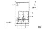
図7は、本実施形態に係る表示位置候補の他の例を示す概念図である。
図7と図6との差異は、図6においてグリッドG1の代わりにグリッドG2が示されている点である。グリッドG1、G2間では、それぞれのグリッドを形成する各セルに付されている番号、即ちアイコンを配置する順序を示す番号が異なる。
図7に示す例では、タッチセンサ103の左端と右端のうち、タッチ位置T1に近い側、つまり最右列のセルにおいて、上端のセルから下端のセルに1−4と順序付けられている。その後、順次左側に隣接する列のセルにおいて5−8、等と順序付けられている。このように、表示制御部115(図3)は、上端のセルから下端のセルの順に、左端と右端のうちタッチ位置T1に近い側のセルから遠い側のセルの順に表示位置候補の順序を設定する。これにより、上端のセルほど、また左端と右端のうちタッチ位置T1から近い側のセルほど、優先すべきアイコンを配置することができる。FIG. 7 is a conceptual diagram illustrating another example of display position candidates according to the present embodiment.
The difference between FIG. 7 and FIG. 6 is that a grid G2 is shown instead of the grid G1 in FIG. Between the grids G1 and G2, the numbers assigned to the cells forming the respective grids, that is, the numbers indicating the order in which the icons are arranged are different.
In the example illustrated in FIG. 7, in the left side and the right end of the
(アイコンの順序の例)
次にアイコンの順序の例について説明する。
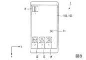
図8は、本実施形態に係るアイコンの順序の一例を示す概念図である。
図8は、図6と同様に表示部102が4個のアイコンi1−i4を表示し、タッチ位置T1は、指がタッチセンサ103に接触している領域の代表点の位置を示す。ここで、アイコンi1−i4のそれぞれの真下に示されている数字1−4は、それぞれのアイコンの順序を示す。この例では、表示制御部115は、それぞれのアイコンを、上端から下端に順序付け、左端及び右端のうちタッチ位置T1から遠い側から近い側に順序付ける。
これにより、タッチ位置T1から遠い側に表示されたアイコンほど順位が高い(即ち、順位を示す数が小さい)表示位置候補に表示されるため、操作が容易になる。(Example of icon order)
Next, an example of the order of icons will be described.
FIG. 8 is a conceptual diagram showing an example of the order of icons according to the present embodiment.
In FIG. 8, the
As a result, the icons displayed on the side farther from the touch position T1 are displayed on the display position candidates with higher ranks (that is, with a smaller number indicating the ranks), so that the operation becomes easier.
図9は、本実施形態に係るアイコンの順序の他の例を示す概念図である。
図9は、図6と同様に表示部102が4個のアイコンi1−i4を表示し、タッチ位置T1において指がタッチセンサ103に接触していることが検知されたことを示す。ここで、アイコンi1−i4のそれぞれの真下に示されている数字3、4、2、1は、それぞれのアイコンの順序を示す。この例では、表示制御部115(図3)は、それぞれのアイコンを、左端及び右端のうちタッチ位置T1から近い側から遠い側に順序付け、かつ同順位の場合は、上端から下端に順序付ける。これにより、左端及び右端のうちタッチ位置T1から近い側に表示されたアイコンほど順位が高い表示位置候補に表示され、アイコン全体の移動量が抑制されるため所望のアプリケーションに係るアイコンを見失うおそれが回避される。FIG. 9 is a conceptual diagram illustrating another example of the order of icons according to the present embodiment.
9 shows that the
なお、図8、図9に示した例において、表示制御部115(図3)は、それぞれのアイコンを、上端から下端に順序付ける代わりに、下端から上端に順序付けてもよい。
その他、表示制御部115(図3)は、タッチ位置T1からその重心点までのユークリッド距離が大きいアイコンから小さいアイコンへ順序付けてもよい。これにより、タッチ位置T1から遠い位置に表示されたアイコンほど順位が高い表示位置候補に表示されるため、操作が容易になる。
また、表示制御部115(図3)は、タッチ位置T1からその重心点までのユークリッド距離が小さいアイコンから大きいアイコンへ順序付けてもよい。これにより、タッチ位置T1から近い位置に表示されたアイコンほど順位が高い表示位置候補に表示されるため、これにより、タッチ位置T1から近い位置に表示されたアイコンほど順位が高い表示位置候補に表示され、アイコン全体の移動量が抑制されるため所望のアプリケーションに係るアイコンを見失うおそれが低減する。In the example shown in FIGS. 8 and 9, the display control unit 115 (FIG. 3) may order the icons from the lower end to the upper end instead of ordering them from the upper end to the lower end.
In addition, the display control unit 115 (FIG. 3) may order an icon having a large Euclidean distance from the touch position T1 to the center of gravity to a small icon. As a result, the icon displayed at a position farther from the touch position T1 is displayed on the display position candidate having a higher rank, and thus the operation is facilitated.
In addition, the display control unit 115 (FIG. 3) may order an icon having a small Euclidean distance from the touch position T1 to the center of gravity to a large icon. As a result, an icon displayed closer to the touch position T1 is displayed as a higher display position candidate, so that an icon displayed closer to the touch position T1 is displayed as a higher display position candidate. Since the movement amount of the entire icon is suppressed, the risk of losing sight of the icon related to the desired application is reduced.
(アイコンの配置の例)
次に、アイコンの配置の例について説明する。
図10は、アイコンの配置の一例を示す概念図である。
図10に示す4個のアイコンi1−i4は、タッチ位置T1の左上、右上、右下、左下にそれぞれ配置されている。アイコンi1−i4のそれぞれの近傍に付されている番号1−4は、それぞれのアイコンの順序を示す。このアイコンの順序は、図8に示されているアイコンの順序と同様であり、図6に示されている各セルの順序と同様である。即ち、図10は、表示制御部115(図3)が図6の表示位置候補にそれぞれ対応する順序と合致する順序(図8)のアイコンを表示部102に表示させることを示す。
なお、本実施形態では、図10に示す例に限られず、表示制御部115(図3)は、図6に示す表示位置候補以外の表示位置候補、例えば、図7に示す表示位置候補を用いてもよい。また、表示制御部115(図3)は、図8に示すアイコンの順序以外のアイコンの順序、例えば、図9に示すアイコンの順序を用いてもよい。(Example of icon arrangement)
Next, an example of icon arrangement will be described.
FIG. 10 is a conceptual diagram showing an example of icon arrangement.
Four icons i1-i4 shown in FIG. 10 are arranged at the upper left, upper right, lower right, and lower left of the touch position T1, respectively. Numbers 1-4 attached to the vicinity of the icons i1-i4 indicate the order of the icons. The order of the icons is the same as the order of the icons shown in FIG. 8, and is the same as the order of the cells shown in FIG. That is, FIG. 10 shows that the display control unit 115 (FIG. 3) causes the
In the present embodiment, the display control unit 115 (FIG. 3) is not limited to the example illustrated in FIG. 10, and the display position candidate other than the display position candidates illustrated in FIG. 6, for example, the display position candidates illustrated in FIG. 7 is used. May be. Further, the display control unit 115 (FIG. 3) may use an icon order other than the icon order shown in FIG. 8, for example, the icon order shown in FIG.
(動作判定処理)
次に、本実施形態に係る動作判定処理について説明する。但し、動作モードの初期設定が動作モード1である場合を例にとる。
図11は、本実施形態に係る動作判定処理を示すフローチャートである。
(ステップS101)動作判定部112は、動作モード1を利用すると判定する。その後、ステップS102に進む。
(ステップS102)タッチセンサ情報処理部114は、タッチセンサ103から操作物が接触した位置を示す位置情報が入力されたか否かを検知する。位置情報の入力が検知された場合(ステップS102 YES)、ステップS104に進む。位置情報の入力が検知されなかった場合(ステップS102 NO)、ステップS103に進む。(Operation judgment process)
Next, the operation determination process according to the present embodiment will be described. However, the case where the initial setting of the operation mode is the
FIG. 11 is a flowchart showing the operation determination process according to the present embodiment.
(Step S101) The
(Step S <b> 102) The touch sensor
(ステップS103)動作判定部112は、押圧検知部111から入力された押圧信号が示す押圧値が、予め定めた閾値よりも小さい状態から、その閾値を越えたか否かを判定する。押圧値が閾値を越えたと判定された場合(ステップS103 YES)、ステップS105に進む。押圧値が閾値を越えていないと判定された場合(ステップS103 NO)、ステップS102に進む。
(ステップS104)表示制御部115は、動作モード1に応じた配置でアイコンを表示部102に表示させる。表示制御部115は、表示させたアイコンの領域とタッチセンサ情報処理部114から入力された位置情報に基づいてアプリケーションの起動や、その実行による処理を制御する。その後、ステップS102に進む。(Step S103) The
(Step S <b> 104) The
(ステップS105)動作判定部112は、動作モード2を利用すると判定する。その後、ステップS106に進む。
(ステップS106)タッチセンサ情報処理部114は、タッチセンサ103から操作物が接触した位置を示す位置情報が入力されたか否かを検知する。位置情報の入力が検知された場合(ステップS106 YES)、ステップS108に進む。位置情報の入力が検知されなかった場合(ステップS106 NO)、ステップS107に進む。(Step S105) The
(Step S <b> 106) The touch sensor
(ステップS107)動作判定部112は、押圧検知部111から入力された押圧信号が示す押圧値が、予め定めた閾値よりも小さい状態から、その閾値を越えたか否かを判定する。押圧値が閾値を越えたと判定された場合(ステップS107 YES)、ステップS101に進む。押圧値が閾値を越えていないと判定された場合(ステップS107 NO)、ステップS106に進む。
(ステップS108)表示制御部115は、動作モード2に応じた配置でアイコンを表示部102に表示させる。但し、動作モード2が継続する場合には、アイコンを再配置する処理を省略してもよい。表示制御部115は、表示させたアイコンの領域とタッチセンサ情報処理部114から入力された位置情報に基づいてアプリケーションの起動や、その実行による処理を制御する。その後、ステップS106に進む。(Step S107) The
(Step S <b> 108) The
(アイコンの配置処理)
次に、ステップS108(図11)において動作モード2に応じてアイコンを配置する処理について説明する。
図12は、本実施形態に係るアイコンの配置処理を示すフローチャートである。
(ステップS201)表示制御部115は、タッチセンサ情報処理部114から入力された位置情報に基づいてタッチ位置を算出し、算出したタッチ位置を基準として予め定めた領域内で所定の間隔で表示位置候補を設定する。表示制御部115は、タッチ位置とそれぞれの表示位置候補との関係に基づいて当該表示位置候補の順序を設定する。その後、ステップS202に進む。
(ステップS202)表示制御部115は、算出したタッチ位置と表示部102に表示されているアイコンの位置との関係に基づいて当該アイコンの順序を設定する。その後、ステップS203に進む。
(ステップS203)表示制御部115は、定めた表示位置候補にそれぞれ対応する順序と合致したアイコンを配置し、その配置された位置にアイコンを表示部102に表示させる。その後、図12のフローチャートの処理を終了し、ステップS106(図11)に進む。(Icon arrangement processing)
Next, processing for arranging icons in accordance with
FIG. 12 is a flowchart showing icon arrangement processing according to the present embodiment.
(Step S <b> 201) The
(Step S <b> 202) The
(Step S203) The
これにより、ユーザは、タッチセンサ103に指を接触していない場合に、電子機器1の外枠部に設置された押圧センサ101に加えた押圧力に基づき、動作モードを切り替えることができる。そのため、ユーザが意図せずにタッチセンサ103に指を接触し続けても動作モードに応じてアイコンの配置が切り替わらないため、片手による操作性が向上する。また、位置情報が入力された場合に、この位置情報に基づく処理が動作モードを判定する処理よりも優先されるため、これらの処理が互いに競合することが回避される。 Accordingly, the user can switch the operation mode based on the pressing force applied to the
以上に説明したように、本実施形態は、操作入力を受け付けた位置を検出し、操作入力を受け付ける領域とは異なる所定の位置で検出した押圧による押圧値に基づいて予め定めた複数の動作モードのうちのいずれか用いるかを判定する。また、本実施形態は、操作入力を受け付ける範囲と機能を示すアイコン等の画面部品を押圧値に基づいて判定した動作モードに応じた配置で表示する。そのため、ユーザは、意図せずに操作入力を行っても所定の位置に押圧を加えない限り動作モードに応じて画面部品の配置が変更しないため、操作性が向上する。 As described above, the present embodiment detects a position at which an operation input is received, and a plurality of operation modes determined in advance based on a pressing value detected by a press detected at a predetermined position different from the area where the operation input is received. Is used. Further, in the present embodiment, the range for accepting the operation input and the screen components such as icons indicating functions are displayed in an arrangement according to the operation mode determined based on the pressed value. Therefore, even if the user performs an operation input unintentionally, the arrangement of the screen components does not change according to the operation mode unless pressing is performed at a predetermined position, so that the operability is improved.
(第2の実施形態)
次に、本発明の第2の実施形態について説明する。上述した実施形態と同一の構成について同一の符号を付して説明を援用する。
本実施形態に係る電子機器2は、電子機器1(図3)において表示制御部115の代わりに表示制御部215(図示せず)を備え、その他の点では電子機器1と同様な構成を備える。
表示制御部215は、表示制御部115(図3)と同様な構成を備え、さらに次の処理を行う。表示制御部215は、位置情報が示す位置が変化した方向に応じた方向に、その位置の変化量よりも大きい変化量で、表示部102に表示されたアイコンの表示位置を変更させる。位置情報が示す位置が変化した方向に応じた方向とは、位置情報が示す位置が変化した方向と同一の方向であってもよいし、その変化した方向と反対の方向であってもよい。表示位置を変更する方向を位置情報が示す位置が変化した方向と同一の方向とするか否かは、OS、アプリケーション、画面部品の種類等により予め定められていてもよい。表示位置の変化率、つまり表示位置の変化量の位置情報が示す位置の変化量に対する割合も、OS、アプリケーション、画面部品の種類等により予め定められていてもよい。この処理を行う契機は、例えば、前述したアイコンを配置する処理が完了した後、又はタッチセンサ情報処理部114から入力された位置情報が示す位置が少なくとも予め定めた時間の閾値(例えば、0.2秒)より長い時間継続して変化する場合である。(Second Embodiment)
Next, a second embodiment of the present invention will be described. The same reference numerals are assigned to the same configurations as those in the above-described embodiment, and the description is incorporated.
The
The display control unit 215 has the same configuration as the display control unit 115 (FIG. 3), and further performs the following processing. The display control unit 215 changes the display position of the icon displayed on the
そこで、ユーザが操作物をタッチセンサ103の表面に接触させながら移動させると(スライド動作)、操作物の位置が表示部102に表示されたいずれかのアイコンの範囲に含まれ、アイコンが選択されることがある。その状態で、ユーザが操作物をタッチセンサ103から離すと、そのアイコンの選択が確定され、例えば、そのアイコンに係るアプリケーションが起動する。 Therefore, when the user moves the operation article while making contact with the surface of the touch sensor 103 (slide operation), the position of the operation article is included in the range of any icon displayed on the
(表示位置の制御例)
次に、本実施形態に係るアイコンの表示位置の制御例について説明する。
図13は、本実施形態に係る制御前におけるアイコンの配置の一例を示す概念図である。
図13において、縦長の破線からなる矩形の領域は、アイコン群ig1を示す。アイコン群ig1には、X方向に3個、Y方向に5個、計15個のアイコンが配列されている。これらのアイコンは、それぞれ表示部102が表示するアイコンである。
図14は、本実施形態に係る制御後におけるアイコンの配置の一例を示す概念図である。
図14は、アイコン群ig1が図13よりも右下に変位していることを示す。×印を起点とする網掛けの矢印ar1は、タッチ位置T1がその起点から終点まで移動したことを示す。×印を起点とする薄く塗りつぶした矢印ar2は、表示部102に表示されている画像がその起点から終点まで移動したことを示す。この矢印の向きと長さは、それぞれアイコン群ig1の移動方向と移動量を示す。つまり、図14は、図13においてタッチ位置T1から離れた位置(例えば、左上端)に表示されたアイコンを、指を移動させた移動量よりも大きく移動させることができることを示す。(Display position control example)
Next, a control example of the icon display position according to the present embodiment will be described.
FIG. 13 is a conceptual diagram showing an example of icon arrangement before control according to the present embodiment.
In FIG. 13, a rectangular area composed of a vertically long broken line indicates an icon group ig1. The icon group ig1 has a total of 15 icons arranged in three in the X direction and five in the Y direction. These icons are icons that the
FIG. 14 is a conceptual diagram showing an example of icon arrangement after control according to the present embodiment.
FIG. 14 shows that the icon group ig1 is displaced to the lower right of FIG. A shaded arrow ar1 starting from the x mark indicates that the touch position T1 has moved from the start point to the end point. A thinly-painted arrow ar2 starting from the x mark indicates that the image displayed on the
以上に説明したように、本実施形態では操作入力を受け付けた位置が変化した方向に応じた方向に、その位置の変化量よりも大きい変化量で表示させた画面部品の表示位置を変更する。そのため、従って、指等の操作物が届かなかった位置に表示された画面部品が、その位置を操作物が届く位置に移動するため、操作性が向上する。 As described above, in the present embodiment, the display position of the screen component displayed with a change amount larger than the change amount of the position is changed in a direction corresponding to the direction in which the position where the operation input is received is changed. Therefore, the screen component displayed at the position where the operation article such as a finger did not reach moves to the position where the operation article reaches, and the operability is improved.
(第3の実施形態)
次に、本発明の第3の実施形態について説明する。上述した実施形態と同一の構成について同一の符号を付して説明を援用する。
本実施形態に係る電子機器3は、電子機器1(図3)において動作判定部112の代わりに動作判定部312(図示せず)を備え、その他の点では電子機器1と同様な構成を備える。
動作判定部312は、動作判定部112(図3)と同様な構成を備える。但し、動作判定部312は、例えば、押圧検知部111から入力された押圧信号が示す押圧値が、制御情報記憶部113から読み出した閾値よりも大きいか否かを判定する。その閾値よりも大きいと判定した場合には、動作判定部312は、動作モード2を用いると判定する。その閾値よりも小さいと判定した場合には、動作判定部312は、動作モード1を用いると判定する。(Third embodiment)
Next, a third embodiment of the present invention will be described. The same reference numerals are assigned to the same configurations as those in the above-described embodiment, and the description is incorporated.
The
The operation determination unit 312 has the same configuration as the operation determination unit 112 (FIG. 3). However, the operation determination unit 312 determines, for example, whether or not the pressing value indicated by the pressing signal input from the
次に、本実施形態に係る動作判定処理について説明する。但し、動作モードの初期設定が動作モード1である場合を例にとる。
図15は、本実施形態に係る動作判定処理を示すフローチャートである。
本実施形態に係る動作判定処理は、図11に示す動作判定処理においてステップS103、S107の代わりに、ステップS303、S307を有する。ここで、ステップS102において、位置情報の入力が検知されなかった場合(ステップS102 NO)、ステップS303に進む。Next, the operation determination process according to the present embodiment will be described. However, the case where the initial setting of the operation mode is the
FIG. 15 is a flowchart showing an operation determination process according to the present embodiment.
The operation determination process according to the present embodiment includes steps S303 and S307 instead of steps S103 and S107 in the operation determination process shown in FIG. If no position information input is detected in step S102 (NO in step S102), the process proceeds to step S303.
(ステップS303)動作判定部312は、押圧検知部111から入力された押圧信号が示す押圧値が、予め定めた閾値よりも大きいか否かを判定する。押圧値が閾値よりも大きいと判定された場合(ステップS303 YES)、ステップS105に進む。押圧値が閾値よりも大きくないと判定された場合(ステップS303 NO)、ステップS102に進む。そして、ステップS106において、位置情報の入力が検知されなかった場合(ステップS106 NO)、ステップS307に進む。
(ステップS307)動作判定部312は、押圧検知部111から入力された押圧信号が示す押圧値が、予め定めた閾値よりも小さいか否かを判定する。押圧値が閾値よりも小さいと判定された場合(ステップS307 YES)、ステップS101に進む。押圧値が閾値よりも小さくないと判定された場合(ステップS307 NO)、ステップS106に進む。(Step S303) The operation determination unit 312 determines whether or not the pressing value indicated by the pressing signal input from the
(Step S307) The operation determination unit 312 determines whether or not the pressing value indicated by the pressing signal input from the
なお、電子機器3は、表示制御部115の代わりに上述した表示制御部215(図示せず)を備えてもよい。
また、動作判定部312は、ステップS303で動作モード1を用いている状態から動作モード2を用いることを判定するための閾値1と、ステップS307で動作モード2を用いている状態から動作モード1を用いることを判定するための閾値2とが異なっていてもよい。例えば、閾値1は閾値2よりも大きくてもよい。これにより、動作モード1から動作モード2への切り替えよりも、動作モード2から動作モード1への切り替えが容易になる。これにより、ユーザが誤って押圧を加えた場合でも通常用いられる動作モード1が用いられる可能性が高くなるため、操作性が損なわれることが回避される。The
In addition, the operation determination unit 312 determines the use of the
上述したように、本実施形態では、押圧値が閾値よりも大きいとき、動作モード2が用いられ、押圧値が閾値ほど大きくないとき、動作モード1が用いられる。これにより、ユーザが操作入力を受け付ける領域とは異なる所定の位置に押圧したか否かにより、動作モード2を用いるか動作モード1を用いるかが制御されるので操作性が向上する。 As described above, in this embodiment, the
(変形例)
上述した実施形態では、動作モード2に応じてアイコンを配置する処理(図12)において、表示制御部115、215は、表示位置候補に各アイコンの代表点(例えば、重心点)に配置するため、アイコンの大きさに関わらず各アイコンが配置される。ここで、それぞれアイコンが配置されている互いに隣接する表示位置候補の間隔よりも、それぞれのアイコンの方が大きい場合には、その隣接するアイコンが重複することがある。その場合には、表示制御部115、215は、アイコンが重複する領域について、その順序が高い方のアイコンを優先して表示してもよい。また、表示制御部115、215は、その領域が選択された場合には、その順序が高い方のアイコンが選択されたと判定してもよい。(Modification)
In the embodiment described above, in the process of arranging icons according to the operation mode 2 (FIG. 12), the
上述した実施形態では、表示制御部115、215は、各アイコンの位置を起点から終点まで漸次変化させてもよい(アニメーションでの遷移)。起点は、動作モード2に応じてアイコンを配置する処理(図12)を行う前における各アイコンの位置であり(図13)、終点は、その処理を行った後における各アイコンの位置である(図14)。そこで、表示制御部115、215は、例えば、各アイコンについて起点から終点までの間を予め定めたフレーム数(例えば、12)で等分した等分点を算出する。表示制御部115、215は、起点に近い順に前回のフレームにおける等分点(但し、初期において起点)とは隣接する等分点(但し、最後のフレームでは終点)にそれぞれのアイコンを配置した画像をフレーム毎に生成し、生成した画像を表示部102に表示させる。
上述した実施形態では、画面部品として主にアイコンを用いる場合を例にとって説明したが、アイコンに限られず、ボタン、リンク、その他の画面部品を用いてもよい。In the embodiment described above, the
In the embodiment described above, the case where icons are mainly used as screen components has been described as an example. However, the present invention is not limited to icons, and buttons, links, and other screen components may be used.
なお、本発明に係る電子機器は、以下の態様でも実施することができる。
(1)操作入力を受け付けた位置を検出する位置検出部と、前記位置検出部とは異なる位置への押圧による押圧値を検出する押圧検出部と、前記押圧検出部が検出した押圧値に基づいて予め定めた複数の動作モードのうちのいずれか用いるかを判定する動作判定部と、前記位置検出部が操作入力を受け付ける範囲と機能を示す画面部品を表示する表示部と、前記動作判定部が判定した動作モードに応じた配置で前記画面部品を前記表示部に表示させる表示制御部と、を備えることを特徴とする電子機器。The electronic device according to the present invention can also be implemented in the following modes.
(1) Based on a position detection unit that detects a position at which an operation input is received, a pressure detection unit that detects a pressure value due to pressing to a position different from the position detection unit, and a pressure value detected by the pressure detection unit. An operation determination unit that determines which one of a plurality of predetermined operation modes is used, a display unit that displays a screen component indicating a range and a function in which the position detection unit receives an operation input, and the operation determination unit An electronic device comprising: a display control unit configured to display the screen component on the display unit in an arrangement according to the operation mode determined by.
(2)前記動作判定部は、前記押圧検出部が検出した押圧値が予め定めた閾値よりも低い状態から高い状態になったとき前記複数の動作モードのうち現在用いている動作モードとは異なる他の動作モードを用いると判定することを特徴とする(1)の電子機器。(2) The operation determination unit is different from the currently used operation mode among the plurality of operation modes when the press value detected by the press detection unit changes from a state lower than a predetermined threshold value to a higher state. The electronic device according to (1), wherein it is determined that another operation mode is used.
(3)前記動作判定部は、前記動作モードの数は2個であって、前記動作判定部は、前記押圧検出部が検出した押圧値が予め定めた閾値よりも小さいとき、前記2個のうち一方の動作モードを用い、前記押圧検出部が検出した押圧値が前記閾値よりも大きいとき前記2個のうち他方の動作モードを用いることを特徴とする(1)の電子機器。(3) The operation determination unit has two operation modes, and the operation determination unit has the two operation modes when the pressure value detected by the pressure detection unit is smaller than a predetermined threshold value. The electronic device according to (1), wherein one of the two operation modes is used when one of the two operation modes is used and the pressing value detected by the pressing detection unit is greater than the threshold value.
(4)前記表示制御部は、前記位置検出部が検出した位置から予め定めた範囲内に、前記表示部に画面部品を表示する位置の候補である表示位置候補を定め、前記位置検出部が検出した位置と前記表示部に表示された画面部品のそれぞれの位置との関係に基づいて当該それぞれの画面部品を前記定めた表示位置候補のいずれかに表示させることを特徴とする(1)から(3)のいずれかの電子機器。(4) The display control unit determines a display position candidate that is a position candidate for displaying a screen component on the display unit within a predetermined range from the position detected by the position detection unit, and the position detection unit Based on the relationship between the detected position and the position of each of the screen parts displayed on the display unit, each of the screen parts is displayed on any of the predetermined display position candidates (1) The electronic device according to any one of (3).
(5)前記表示制御部は、前記位置検出部が前記操作入力を受け付けた位置が変化した方向に応じた方向に、前記位置の変化量よりも大きい変化量で前記表示させた画面部品の表示位置を変更することを特徴とする(4)の電子機器。(5) The display control unit displays the displayed screen component with a change amount larger than the change amount of the position in a direction corresponding to the direction in which the position at which the position detection unit has received the operation input has changed. The electronic device according to (4), wherein the position is changed.
(6)操作入力を受け付けた位置を検出する位置検出部と、前記位置検出部とは異なる位置への押圧による押圧値を検出する押圧検出部とを備える電子機器における情報処理方法であって、前記押圧検出部が検出した押圧値に基づいて予め定めた複数の動作モードのうちのいずれか用いるかを判定する動作判定過程と、前記動作判定過程で判定した動作モードに応じた配置で、前記位置検出部が操作入力を受け付ける範囲と機能を示す画面部品を表示部に表示させる表示制御過程とを有することを特徴とする情報処理方法。(6) An information processing method in an electronic device including a position detection unit that detects a position at which an operation input is received, and a press detection unit that detects a press value resulting from pressing to a position different from the position detection unit, An operation determination process for determining whether to use any one of a plurality of predetermined operation modes based on a pressure value detected by the pressure detection unit, and an arrangement according to the operation mode determined in the operation determination process, What is claimed is: 1. An information processing method comprising: a display control process for causing a display unit to display a screen part showing a function and a range in which a position detection unit receives operation input
(7)操作入力を受け付けた位置を検出する位置検出部と、前記位置検出部とは異なる位置への押圧による押圧値を検出する押圧検出部とを備える電子機器のコンピュータに、前記押圧検出部が検出した押圧値に基づいて予め定めた複数の動作モードのうちのいずれか用いるかを判定する動作判定手順、前記動作判定手順で判定した動作モードに応じた配置で、前記位置検出部が操作入力を受け付ける範囲と機能を示す画面部品を表示部に表示させる表示制御手順、を実行させるための情報処理プログラム。(7) The press detection unit in a computer of an electronic device including a position detection unit that detects a position at which an operation input is received and a press detection unit that detects a press value by pressing to a position different from the position detection unit. An operation determination procedure for determining whether to use one of a plurality of predetermined operation modes based on the detected pressure value, and the position detection unit is operated according to the operation mode determined in the operation determination procedure. An information processing program for executing a display control procedure for causing a display unit to display a screen component indicating a range and function for receiving an input.
上述した(1)、(6)又は(7)によれば、ユーザは、意図せずに操作入力を行っても所定の位置に押圧を加えない限り動作モードに応じて画面部品の配置が変更しないため、操作性が向上する。
上述した(2)によれば、所定の位置に押圧を新たに加えることで画面部品の配置を変更することができる。
上述した(3)によれば、所定の位置に押圧を加えるか否かにより2種類の画面部品の配置のうちいずれかを切り替えることができる。
上述した(4)によれば、操作入力を行った位置から予め定めた範囲内に、その位置と画面部品の位置との関係に基づいて所定の規則に基づいてそれぞれの画面部品が配置されるため、画面部品への操作が容易になる。
上述した(5)によれば、操作物が届かなかった位置に表示された画面部品が、その位置を操作物が届く位置に移動するため、操作性が向上する。According to the above (1), (6), or (7), even if the user performs an operation input unintentionally, the arrangement of the screen components is changed according to the operation mode as long as the user does not press the predetermined position. Therefore, the operability is improved.
According to (2) described above, it is possible to change the arrangement of the screen components by newly applying a press at a predetermined position.
According to (3) described above, it is possible to switch between two types of screen component arrangements depending on whether or not a predetermined position is pressed.
According to the above (4), each screen component is arranged based on a predetermined rule based on the relationship between the position and the position of the screen component within a predetermined range from the position where the operation input is performed. Therefore, it becomes easy to operate the screen parts.
According to the above (5), the screen component displayed at the position where the operation article has not arrived moves to the position where the operation article reaches, so that the operability is improved.
なお、上述した実施形態における電子機器1、1b、1c、2、3の一部、例えば、押圧検知部111、動作判定部112、312、タッチセンサ情報処理部114、表示制御部115、215及びアプリケーション実行部116をコンピュータで実現するようにしてもよい。その場合、この制御機能を実現するためのプログラムをコンピュータ読み取り可能な記録媒体に記録して、この記録媒体に記録されたプログラムをコンピュータシステムに読み込ませ、実行することによって実現してもよい。なお、ここでいう「コンピュータシステム」とは、電子機器1、1b、1c、2、3のいずれかに内蔵されたコンピュータシステムであって、OSや周辺機器等のハードウェアを含むものとする。また、「コンピュータ読み取り可能な記録媒体」とは、フレキシブルディスク、光磁気ディスク、ROM、CD−ROM等の可搬媒体、コンピュータシステムに内蔵されるハードディスク等の記憶装置のことをいう。さらに「コンピュータ読み取り可能な記録媒体」とは、インターネット等のネットワークや電話回線等の通信回線を介してプログラムを送信する場合の通信線のように、短時間、動的にプログラムを保持するもの、その場合のサーバやクライアントとなるコンピュータシステム内部の揮発性メモリのように、一定時間プログラムを保持しているものも含んでもよい。また上記プログラムは、前述した機能の一部を実現するためのものであってもよく、さらに前述した機能をコンピュータシステムにすでに記録されているプログラムとの組み合わせで実現できるものであってもよい。
また、上述した実施形態における電子機器1、1b、1c、2、3の一部、または全部を、LSI(Large Scale Integration)等の集積回路として実現してもよい。電子機器1、1b、1c、2、3の各機能ブロックは個別にプロセッサ化してもよいし、一部、または全部を集積してプロセッサ化してもよい。また、集積回路化の手法はLSIに限らず専用回路、または汎用プロセッサで実現してもよい。また、半導体技術の進歩によりLSIに代替する集積回路化の技術が出現した場合、当該技術による集積回路を用いてもよい。Note that some of the
In addition, some or all of the
以上、図面を参照してこの発明の一実施形態について詳しく説明してきたが、具体的な構成は上述のものに限られることはなく、この発明の要旨を逸脱しない範囲内において様々な設計変更等をすることが可能である。 As described above, the embodiment of the present invention has been described in detail with reference to the drawings. However, the specific configuration is not limited to the above, and various design changes and the like can be made without departing from the scope of the present invention. It is possible to
1、1b、1c、2、3…電子機器、
101、101b−1、101b−2、101c−1、101c−2…押圧センサ、
102…表示部、103…タッチセンサ、104…保護パネル、105…筐体、
110…制御部、111…押圧検知部、112、312…動作判定部、
113…制御情報記憶部、114…タッチセンサ情報処理部、
115、215…表示制御部、116…アプリケーション実行部1, 1b, 1c, 2, 3 ... electronic equipment,
101, 101b-1, 101b-2, 101c-1, 101c-2 ... pressure sensors,
102 ... Display unit, 103 ... Touch sensor, 104 ... Protection panel, 105 ... Housing
110 ... Control unit, 111 ... Press detection unit, 112, 312 ... Operation determination unit,
113 ... Control information storage unit, 114 ... Touch sensor information processing unit,
115, 215 ... display control unit, 116 ... application execution unit
Claims (5)
Translated fromJapanese前記位置検出部とは異なる位置への押圧による押圧値を検出する押圧検出部と、
前記押圧検出部が検出した押圧値に基づいて予め定めた複数の動作モードのうちのいずれか用いるかを判定する動作判定部と、
前記位置検出部が操作入力を受け付ける範囲と機能を示す画面部品を表示する表示部と、
前記動作判定部が判定した動作モードに応じた配置で前記画面部品を前記表示部に表示させる表示制御部と、
を備えることを特徴とする電子機器。A position detection unit that detects a position at which an operation input is received;
A pressure detection unit that detects a pressure value by pressing to a position different from the position detection unit;
An operation determination unit for determining whether to use any one of a plurality of predetermined operation modes based on the press value detected by the press detection unit;
A display unit for displaying a screen component indicating a range and a function in which the position detection unit receives an operation input;
A display control unit for displaying the screen component on the display unit in an arrangement according to the operation mode determined by the operation determination unit;
An electronic device comprising:
Priority Applications (1)
| Application Number | Priority Date | Filing Date | Title |
|---|---|---|---|
| JP2013023817AJP2014153956A (en) | 2013-02-08 | 2013-02-08 | Electronic apparatus |
Applications Claiming Priority (1)
| Application Number | Priority Date | Filing Date | Title |
|---|---|---|---|
| JP2013023817AJP2014153956A (en) | 2013-02-08 | 2013-02-08 | Electronic apparatus |
Publications (1)
| Publication Number | Publication Date |
|---|---|
| JP2014153956Atrue JP2014153956A (en) | 2014-08-25 |
Family
ID=51575758
Family Applications (1)
| Application Number | Title | Priority Date | Filing Date |
|---|---|---|---|
| JP2013023817APendingJP2014153956A (en) | 2013-02-08 | 2013-02-08 | Electronic apparatus |
Country Status (1)
| Country | Link |
|---|---|
| JP (1) | JP2014153956A (en) |
Cited By (3)
| Publication number | Priority date | Publication date | Assignee | Title |
|---|---|---|---|---|
| CN104866199A (en)* | 2015-05-29 | 2015-08-26 | 小米科技有限责任公司 | Method, apparatus, and electronic device for processing key operation in single-hand mode |
| WO2016143241A1 (en)* | 2015-03-09 | 2016-09-15 | ソニー株式会社 | Input device and electrical apparatus |
| JP2018173898A (en)* | 2017-03-31 | 2018-11-08 | ブラザー工業株式会社 | Print control program, print control apparatus, and print control method |
- 2013
- 2013-02-08JPJP2013023817Apatent/JP2014153956A/enactivePending
Cited By (6)
| Publication number | Priority date | Publication date | Assignee | Title |
|---|---|---|---|---|
| WO2016143241A1 (en)* | 2015-03-09 | 2016-09-15 | ソニー株式会社 | Input device and electrical apparatus |
| US10620757B2 (en) | 2015-03-09 | 2020-04-14 | Sony Corporation | Input device and electrical apparatus |
| CN104866199A (en)* | 2015-05-29 | 2015-08-26 | 小米科技有限责任公司 | Method, apparatus, and electronic device for processing key operation in single-hand mode |
| US10025393B2 (en) | 2015-05-29 | 2018-07-17 | Xiaomi Inc. | Button operation processing method in single-hand mode |
| CN104866199B (en)* | 2015-05-29 | 2019-02-12 | 小米科技有限责任公司 | Button operation processing method and processing device under singlehanded mode, electronic equipment |
| JP2018173898A (en)* | 2017-03-31 | 2018-11-08 | ブラザー工業株式会社 | Print control program, print control apparatus, and print control method |
Similar Documents
| Publication | Publication Date | Title |
|---|---|---|
| JP6321113B2 (en) | Handheld electronic device with multi-touch sensing device | |
| JP6258996B2 (en) | Electronic device with sidewall display | |
| JP6109788B2 (en) | Electronic device and method of operating electronic device | |
| WO2009080765A1 (en) | A portable electronic apparatus, and a method of controlling a user interface thereof | |
| US20180011561A1 (en) | Information processing apparatus, input apparatus, method of controlling information processing apparatus, method of controlling input apparatus, and program | |
| JP5997921B2 (en) | Character input method and character input device | |
| JP6183820B2 (en) | Terminal and terminal control method | |
| KR20140037320A (en) | Mobile terminal | |
| JP2014016743A (en) | Information processing device, information processing device control method and information processing device control program | |
| JP2014153956A (en) | Electronic apparatus | |
| JP6123106B2 (en) | Electronics | |
| JP2014182429A (en) | Information processor, information processing method and information processing program | |
| JP5995171B2 (en) | Electronic device, information processing method, and information processing program | |
| WO2015098061A1 (en) | Electronic instrument | |
| KR101678213B1 (en) | An apparatus for user interface by detecting increase or decrease of touch area and method thereof | |
| JP2012238128A (en) | Information device having back-face input function, back-face input method, and program | |
| KR20100042762A (en) | Method of performing mouse interface in portable terminal and the portable terminal | |
| CN108700990A (en) | A kind of screen locking method, terminal and screen locking device | |
| JP2015106173A (en) | Electronics | |
| JP6367547B2 (en) | Electronics | |
| JP5624662B2 (en) | Electronic device, display control method and program | |
| JP2013206299A (en) | Information input device | |
| US20110001716A1 (en) | Key module and portable electronic device | |
| JP2014075022A (en) | Input device | |
| JP5774364B2 (en) | Page view switching device |
Legal Events
| Date | Code | Title | Description |
|---|---|---|---|
| RD04 | Notification of resignation of power of attorney | Free format text:JAPANESE INTERMEDIATE CODE: A7424 Effective date:20150518 |