JP2014149719A - Tilt mechanism for information equipment - Google Patents
Tilt mechanism for information equipmentDownload PDFInfo
- Publication number
- JP2014149719A JP2014149719AJP2013018514AJP2013018514AJP2014149719AJP 2014149719 AJP2014149719 AJP 2014149719AJP 2013018514 AJP2013018514 AJP 2013018514AJP 2013018514 AJP2013018514 AJP 2013018514AJP 2014149719 AJP2014149719 AJP 2014149719A
- Authority
- JP
- Japan
- Prior art keywords
- link
- display unit
- main body
- lock
- state
- Prior art date
- Legal status (The legal status is an assumption and is not a legal conclusion. Google has not performed a legal analysis and makes no representation as to the accuracy of the status listed.)
- Granted
Links
Images


Classifications
- G—PHYSICS
- G06—COMPUTING OR CALCULATING; COUNTING
- G06F—ELECTRIC DIGITAL DATA PROCESSING
- G06F1/00—Details not covered by groups G06F3/00 - G06F13/00 and G06F21/00
- G06F1/16—Constructional details or arrangements
- G06F1/1601—Constructional details related to the housing of computer displays, e.g. of CRT monitors, of flat displays
- G—PHYSICS
- G06—COMPUTING OR CALCULATING; COUNTING
- G06F—ELECTRIC DIGITAL DATA PROCESSING
- G06F1/00—Details not covered by groups G06F3/00 - G06F13/00 and G06F21/00
- G06F1/16—Constructional details or arrangements
- G06F1/1613—Constructional details or arrangements for portable computers
- G06F1/1615—Constructional details or arrangements for portable computers with several enclosures having relative motions, each enclosure supporting at least one I/O or computing function
- G06F1/1616—Constructional details or arrangements for portable computers with several enclosures having relative motions, each enclosure supporting at least one I/O or computing function with folding flat displays, e.g. laptop computers or notebooks having a clamshell configuration, with body parts pivoting to an open position around an axis parallel to the plane they define in closed position
- G06F1/162—Constructional details or arrangements for portable computers with several enclosures having relative motions, each enclosure supporting at least one I/O or computing function with folding flat displays, e.g. laptop computers or notebooks having a clamshell configuration, with body parts pivoting to an open position around an axis parallel to the plane they define in closed position changing, e.g. reversing, the face orientation of the screen with a two degrees of freedom mechanism, e.g. for folding into tablet PC like position or orienting towards the direction opposite to the user to show to a second user
- G—PHYSICS
- G06—COMPUTING OR CALCULATING; COUNTING
- G06F—ELECTRIC DIGITAL DATA PROCESSING
- G06F1/00—Details not covered by groups G06F3/00 - G06F13/00 and G06F21/00
- G06F1/16—Constructional details or arrangements
- G06F1/1613—Constructional details or arrangements for portable computers
- G06F1/1615—Constructional details or arrangements for portable computers with several enclosures having relative motions, each enclosure supporting at least one I/O or computing function
- G06F1/1624—Constructional details or arrangements for portable computers with several enclosures having relative motions, each enclosure supporting at least one I/O or computing function with sliding enclosures, e.g. sliding keyboard or display
- G—PHYSICS
- G06—COMPUTING OR CALCULATING; COUNTING
- G06F—ELECTRIC DIGITAL DATA PROCESSING
- G06F1/00—Details not covered by groups G06F3/00 - G06F13/00 and G06F21/00
- G06F1/16—Constructional details or arrangements
- G06F1/1613—Constructional details or arrangements for portable computers
- G06F1/1633—Constructional details or arrangements of portable computers not specific to the type of enclosures covered by groups G06F1/1615 - G06F1/1626
- G06F1/1675—Miscellaneous details related to the relative movement between the different enclosures or enclosure parts
- G06F1/1681—Details related solely to hinges
- G—PHYSICS
- G06—COMPUTING OR CALCULATING; COUNTING
- G06F—ELECTRIC DIGITAL DATA PROCESSING
- G06F1/00—Details not covered by groups G06F3/00 - G06F13/00 and G06F21/00
- G06F1/16—Constructional details or arrangements
- G06F1/1613—Constructional details or arrangements for portable computers
- G06F1/1633—Constructional details or arrangements of portable computers not specific to the type of enclosures covered by groups G06F1/1615 - G06F1/1626
- G06F1/1675—Miscellaneous details related to the relative movement between the different enclosures or enclosure parts
- G06F1/1679—Miscellaneous details related to the relative movement between the different enclosures or enclosure parts for locking or maintaining the movable parts of the enclosure in a fixed position, e.g. latching mechanism at the edge of the display in a laptop or for the screen protective cover of a PDA
Landscapes
- Engineering & Computer Science (AREA)
- Theoretical Computer Science (AREA)
- Computer Hardware Design (AREA)
- Physics & Mathematics (AREA)
- General Engineering & Computer Science (AREA)
- Human Computer Interaction (AREA)
- General Physics & Mathematics (AREA)
- Mathematical Physics (AREA)
- Devices For Indicating Variable Information By Combining Individual Elements (AREA)
- Casings For Electric Apparatus (AREA)
- Pivots And Pivotal Connections (AREA)
- Telephone Set Structure (AREA)
Abstract
Translated fromJapaneseDescription
Translated fromJapanese本出願は、情報機器の本体部に重なるディスプレイ部の上端部を引き上げ、下端部を本体部上でスライドさせて、ディスプレイ部を本体部の上でチルトさせた後に、ディスプレイ部のチルト角度を変更することができる情報機器のチルト機構に関する。 This application raises the upper end of the display unit that overlaps the main unit of the information device, slides the lower end on the main unit, tilts the display unit on the main unit, and then changes the tilt angle of the display unit. The present invention relates to a tilt mechanism of an information device that can be used.
近年、タブレットPC(PC:パーソナルコンピュータ)やノートPC、携帯電話、スマートフォン等の情報機器が普及している。これまでの情報機器では、本体部とディスプレイ部が重なって閉じた状態でディスプレイ部の表示面が内側に隠れており、本体部にヒンジ結合されたディスプレイ部を開くと表示面が現れるようになっている製品が多く見られた。一方、近年の情報機器には、タッチパネルの普及により、本体部とディスプレイ部が重なって閉じた状態でディスプレイ部の表示面が表側に現れており、ディスプレイ部を開いてキーボードを露出させなくてもタッチパネルから入力が行えるものがある。 In recent years, information devices such as a tablet PC (PC: personal computer), a notebook PC, a mobile phone, and a smartphone have become widespread. In conventional information devices, the display surface of the display unit is hidden inside when the main unit and the display unit overlap and are closed, and the display surface appears when the display unit hinged to the main unit is opened. Many products are seen. On the other hand, in recent information devices, due to the widespread use of touch panels, the display surface of the display unit appears on the front side with the main body unit and the display unit overlapped and closed, without having to open the display unit and expose the keyboard. Some can be entered from the touch panel.
特許文献1に開示のノート型のパーソナルコンピューター(PC)では、本体部の両側面に設けられた溝にヒンジが前後方向にスライド可能に取り付けられており、このヒンジに表示部の下端部が回転可能に取り付けられている。特許文献1に開示のノート型のPCでは、ヒンジが本体部の後端部に位置する時にディスプレイ部を本体部側に倒すと表示面が内側に隠れ、ヒンジが本体部の前端部に位置する時にディスプレイ部を本体部側に倒すと表示面が外側になる。即ち、表示面が本体部の上に重なった状態で露出するタブレットPCスタイルと、表示面を本体部の後方でチルトさせることができるノートPCスタイルに使い分けることができる。 In the notebook type personal computer (PC) disclosed in
また、特許文献2には、本体部とディスプレイ部が重なって閉じた状態でディスプレイ部の表示面が表側に現れるので、表示面の上に更に薄い蓋を取り付けて表示面を保護するようにした電子機器が開示されている。特許文献2に開示の電子機器では、表示部の前端に設けられた固定軸が本体部のスライド用レールを移動可能で、本体部に設けたロータリーエンコーダと表示部の中央に設けた回転ヒンジとをリンクアームで結合している。表示部を引き起こすとリンクアームが立ち上がり、固定軸がスライド用レール内を移動することにより、表示部が本体部の後ろ方向へスライドしながらチルトする。ロータリーエンコーダのラッチ機構によりリンクアームを複数の角度で固定することで、表示部のチルト角を複数設定できる。 Further, in
しかし、特許文献2に開示の電子機器では、表示部の本体部からのチルト後の表示部のチルト角変更時に、表示部の下端をキーボードがある手前側に移動させているので、キーボードの奥行方向の長さが短くなって操作性が低下するという課題がある。また、表示部を最も起こした時の表示部の下端位置とキーボードの間のスペースは表示部のチルト角変更動作によって隠れたり露出するので、ここに小さな表示部や操作ボタン等の配置ができず、このスペースを有効利用することができないという課題もある。 However, in the electronic device disclosed in
1つの側面では、本出願は、本体部とディルプレイ部とを備える情報機器において、ディスプレイ部が本体部と重なった状態から、ディスプレイ部を本体部の上でスライド移動と同時にチルトさせてチルト状態にすることができると共に、チルト動作完了後にディスプレイ部の下端部は移動させずにチルト角を変更することが可能な情報機器のチルト機構を提供することを目的とする。 In one aspect, the present application relates to an information device including a main body portion and a display unit, wherein the display portion is tilted simultaneously with a slide movement on the main body portion from a state where the display portion overlaps the main body portion. Another object of the present invention is to provide a tilt mechanism for an information device that can change the tilt angle without moving the lower end of the display unit after the tilt operation is completed.
実施形態の一観点によれば、情報機器の本体部に重なるディスプレイ部の上端部を引き上げ、下端部を本体部上でスライドさせて、ディスプレイ部を本体部の上でチルトさせた後に、ディスプレイ部のチルト角度を変更することが可能な情報機器のチルト機構であって、ディスプレイ部の下端部に設けられた走行ローラと、本体部の上面に設けられ、走行ローラの回転軸を回転可能に係止する回転軸支持部と、本体部に一端が第1回転軸によって回転自在に取り付けられ、他端に第1係合部を備えた第1リンクと、ディスプレイ部に一端が第2回転軸によって回転自在に取り付けられ、他端に第2係合部を備えた第2リンクと、第1係合部と第2係合部とを係合させ、ディスプレイ部が本体部に重なった状態から引き上げられてローラの回転軸が回転軸支持部に係止されるまでは、第1係合部と第2係合部の係合状態を固定し、ローラの回転軸が回転軸支持部に係止された後は、第1係合部と第2係合部の固定係合状態を解除して第1回転軸と第2回転軸間の距離が短くなるように変形可能なリンク機構とを備えることを特徴とする情報機器のチルト機構が提供される。 According to one aspect of the embodiment, after the upper end of the display unit that overlaps the main unit of the information device is pulled up, the lower end is slid on the main unit, and the display unit is tilted on the main unit, the display unit The tilt mechanism of the information device is capable of changing the tilt angle of the travel device. The travel mechanism is provided on the lower end portion of the display unit and the upper surface of the main body unit, and the rotation shaft of the travel roller is rotatable. A rotating shaft support portion that stops, a first link that is rotatably attached to the main body portion by a first rotating shaft and a first engaging portion at the other end, and an end that is connected to the display portion by a second rotating shaft The display unit is pulled up from the state where the display unit is overlapped with the main body unit by engaging the second link having the second engagement unit at the other end with the second link and the first engagement unit and the second engagement unit. Rotating roller Until the rotation shaft support portion is locked to the rotation shaft support portion, the engagement state of the first engagement portion and the second engagement portion is fixed, and after the rotation shaft of the roller is locked to the rotation shaft support portion, A link mechanism that can be deformed so that the distance between the first rotating shaft and the second rotating shaft is shortened by releasing the fixed engaging state of the first engaging portion and the second engaging portion. A device tilt mechanism is provided.
以下、添付図面を用いて本出願の実施形態を、具体的な実施例に基づいて詳細に説明する。なお、構造を容易に理解するために、同じ機能を持つ部材については、形状が異なっても同じ符号を付して説明する。 Hereinafter, embodiments of the present application will be described in detail based on specific examples with reference to the accompanying drawings. In order to easily understand the structure, members having the same function will be described with the same reference numerals even if the shapes are different.
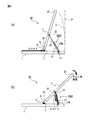
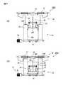
図1(a)は本出願の第1の実施形態の第1の実施例のリンク機構30A1(以後単にリンク機構30A1と記載する)を備えた情報機器50の外観を示す斜視図である。情報機器50には第1の筐体としての本体部1と第2の筐体としてのディスプレイ部2があり、ディスプレイ部2にはタッチパネル付ディスプレイ20が設けられている。本体部1にディスプレイ部2が重ね合わされた状態では、タッチパネル付ディスプレイ20はディスプレイ部2の表側の面に露出している。そして、重ね合わされた本体部1とディスプレイ部2の両方の側面にはディスプレイ部2を本体部1からチルトさせるリンク機構30A1が取り付けられている。なお、以後の説明では、情報機器50を利用者が操作する側を情報機器50の前側とする。 FIG. 1A is a perspective view showing an external appearance of an
リンク機構30A1は、図1(b)に示すように、第1のリンクである本体部側リンク31と、第2のリンクであるディスプレイ部側リンク32とを備えている。本体部側リンク31の一端は、本体部1の後ろ側の側面に第1回転軸11により回転自在に取り付けられており、他端にはディスプレイ部側リンク32と係合する係合部がある。一方、ディスプレイ部側リンク32の一端は、ディスプレイ部2の前側の側面に第2回転軸22により回転自在に取り付けられており、他端には本体部側リンク31と係合する係合部がある。リンク機構30A1では、本体部側リンク31に設けられた溝31Mに、ディスプレイ部側リンク32の係合部が挿入されている。 As shown in FIG. 1B, the link mechanism 30A1 includes a main body unit side link 31 that is a first link and a display unit side link 32 that is a second link. One end of the main body unit side link 31 is rotatably attached to the rear side surface of the
リンク機構30A1における本体部側リンク31とディスプレイ部側リンク32の係合部は、図示しないロック機構によって通常は移動しないように固定されている。従って、リンク機構30A1における第1回転軸11と第2回転軸22との間の距離は、ロック機構のロックを解除しない限り一定である。また、ディスプレイ部2のチルト時に下側となる下端部2Bには、チルト回転軸6に取り付けられた走行ローラ5があり、本体部1の上面には、走行ローラ5が本体部1の面上を移動して来た時に、チルト回転軸6の移動を係止する回転軸支持部7がある。 The engaging portion between the main
本体部1に対してディスプレイ部2をチルトさせる時は、図1(c)に示すように、ディスプレイ部2の上端部2Tを引き上げ、リンク機構30A1によって本体部1に対してディスプレイ部2がスライドとチルト動作を行うようにする。ディスプレイ部2がスライドとチルト動作を開始すると、リンク機構30A1の本体部側リンク31が第1回転軸11を中心にして回転し、ディスプレイ部側リンク32が第2回転軸22を中心にして回転する。そして、ディスプレイ部2の下端部2Bにある走行ローラ5が本体部1の上を走行すると、下端部2Bがスライド移動する。走行ローラ5が本体部1の上を走行するに伴ってディスプレイ部2の上端部2Tが次第にチルトする。この時、リンク機構30A1の第1回転軸11と第2回転軸22の間の距離は変わらない。 When the
図2(a)は図1(c)に示した状態からディスプレイ部2が更にチルトされ、走行ローラ5のチルト回転軸6が回転軸支持部7に係止されてチルト動作が完了した状態を示している。リンク機構30A1の動作によれば、本体部1からディスプレイ部2がチルトしてチルト動作が完了するまでの間に、ディスプレイ部2の上端部2Tが移動する軌跡Lは、本体部1の後ろ側の端部に立てた垂線Pより後ろ側に出ない。よって、リンク機構30A1が取り付けられた情報機器50は、本体部1の後ろ側にスペースのない場所でもディスプレイ部2をチルトさせることができる。 2A shows a state in which the
一方、リンク機構30A1が取り付けられた情報機器50は、本体部1の後ろ側にスペースがある場所では、ディスプレイ部2のチルト角度を、ディスプレイ部2の下端部2Bの位置を移動させることなく変更することができる。この動作を図2(b)を用いて説明する。図2(a)に示すように、ディスプレイ部2のチルトが完了した状態では、走行ローラ5のチルト回転軸6が回転軸支持部7に係止されている。この状態で本体部側リンク31とディスプレイ部側リンク32の係合部の図示しないロック機構を解除すると、ディスプレイ部側リンク32が本体部側リンク31に設けられた溝31M内をスライドする。この結果、ディスプレイ部側リンク32の、溝31M内への収納部分が多くなる。そして、リンク機構30A1における第1回転軸11と第2回転軸22との間の距離が短くなり、図2(b)に示すように、ディスプレイ部2がチルト回転軸6を中心にして回転し、チルト角度を変更できる。 On the other hand, the
図3(a)は図1、図2に示したリンク機構30A1における本体部側リンク31とディスプレイ部側リンク32の係合部の構造の一実施例を示すものであり、本体部側リンク31にはロック機構60が取り付けられている。ロック機構60はスライドロッド61を備えており、このスライドロッド61には貫通孔62が設けられている。スライドロッド61は本体部側リンク31に垂直な方向に移動が可能である。ロック状態では、貫通孔62の位置が本体部側リンク31にある溝31Mの位置と一致していない。このため、ディスプレイ部側リンク32はスライドロッド61によってこれ以上は溝31Mの中に移動できない。また、本体部側リンク31のロック機構60よりもディスプレイ部側リンク32に近い側には、ディスプレイ部側リンク32の本体部側リンク31の溝31M内での移動速度を規制する抑えバネ34が設けられている。 FIG. 3A shows an embodiment of the structure of the engaging portion of the main
図3(b)は図3(a)に示したロック機構60のスライドロッド61の突出部が押し込まれ、スライドロッド61が移動して貫通孔62の位置が本体部側リンク31にある溝31Mの位置に一致した状態を示している。この状態ではディスプレイ部側リンク32の先端部が貫通孔62を通り抜けることができるので、ディスプレイ部側リンク32を本体部側リンク31の溝31Mの中に移動させることが可能である。なお、前述のように、抑えバネ34の付勢力により、ディスプレイ部側リンク32は本体部側リンク31の溝31M内を素早く移動することはできない。 3B shows a
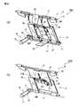
図4(a)は、本出願の第1の実施形態の第2の実施例のリンク機構30A2(以後単にリンク機構30A2と記載する)を備えた情報機器50において、ディスプレイ部2のチルト動作が完了した状態を示す側面図である。リンク機構30A2を除く部分の情報機器50の構成は、リンク機構30A1を備えた情報機器50と同じである。リンク機構30A2は、第1のリンクである本体部側リンク31と、第2のリンクであるディスプレイ部側リンク32とを備えている。本体部側リンク31の一端は、本体部1の後ろ側の側面に第1回転軸11により回転自在に取り付けられており、他端にはディスプレイ部側リンク32と係合する係合部がある。一方、ディスプレイ部側リンク32の一端は、ディスプレイ部2の前側の側面に第2回転軸22により回転自在に取り付けられており、他端には本体部側リンク31と係合する係合部がある。リンク機構30A2では、本体部側リンク31の係合部とディスプレイ部側リンク32の係合部は、第3回転軸33によって結合されている。 FIG. 4A shows the tilt operation of the
リンク機構30A2における本体部側リンク31とディスプレイ部側リンク32の係合部は第3回転軸33によって結合されているが、この結合部は図示しないロック機構によって通常は回転しないように固定されている。従って、リンク機構30A2における第1回転軸11と第2回転軸22との間の距離は、ロック機構のロックを解除しない限り一定である。そして、ディスプレイ部2の下端部2Bにはチルト回転軸6に取り付けられた走行ローラ5があり、本体部1の上面には走行ローラ5が本体部1の面上を移動して来た時にチルト回転軸6の移動を係止する回転軸支持部7がある。 The engaging portion of the main
図4(a)は、本体部1に対してディスプレイ部2の上端部2Tを引き上げ、リンク機構30A2によって本体部1に対してディスプレイ部2にスライドとチルト動作を行わせてディスプレイ部2をチルトさせた状態を示している。本体部1に対してディスプレイ部2にスライドとチルト動作を行わせる時の、リンク機構30A2の第1回転軸11と第2回転軸22の間の距離は変わらない。 In FIG. 4A, the
図4(a)に示す状態で、本体部側リンク31とディスプレイ部側リンク32の係合部に設けられたロック機構のロックを外すと、本体部側リンク31とディスプレイ部側リンク32の係合部は第3回転軸33によって回転可能になる。よって、この状態で本体部側リンク31とディスプレイ部側リンク32の係合部を情報機器50の後ろ側に移動させると、リンク機構30A2が中折れし、第1回転軸11と第2回転軸22との間の距離が短くなる。この結果、図4(b)に示すように、ディスプレイ部2がチルト回転軸6を中心にして回転し、チルト角度を変更できる。この場合、第3回転軸33を備える結合部に本体部側リンク31に対するディスプレイ部側リンク32の回転を抑える機構や回転を段階的に行わせる機構を設けておけば良い。 In the state shown in FIG. 4A, when the lock mechanism provided at the engaging portion between the main
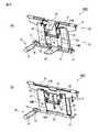
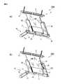
次に、本出願の第2の実施形態のリンク機構について説明する。第1の実施形態のリンク機構30A1、30A2は、本体部1とディスプレイ部2の両方の側面に取り付けられていたが、第2の実施形態のリンク機構は、本体部1の上面とディスプレイ部2の裏面間に取り付けられる。図5(a)は情報機器に取り付ける第2の実施形態の第1の実施例のリンク機構30B1(以後単にリンク機構30B1と記載する)の構造を示す分解斜視図である。 Next, a link mechanism according to a second embodiment of the present application will be described. The link mechanisms 30A1 and 30A2 of the first embodiment are attached to both side surfaces of the
リンク機構30B1は、本体部側に第1回転軸11を備える本体部側リンク31と、ディスプレイ側に第2回転軸22を備えるディスプレイ部側リンク32、第1ブラケット41、第2ブラケット42及び付勢手段であるアシストバネ9とを備えている。この実施例ではアシストバネ9は第2回転軸22に2つ取り付けられている。第2の実施形態では、本体部側リンク31は平板状であり、その幅方向の両側に後述するディスプレイ部側リンク32の自由端部を受け入れる部材を備えている。また、ディスプレイ部側リンク32は、自由端部が本体部側リンク31に収容されると共に、第2回転軸22を備える側が拡幅されて中央部に切欠部25が設けられている。 The link mechanism 30B1 includes a main body portion side link 31 having the
第2回転軸22はこの切欠部25を横断して設けられ、その両端部が第2ブラケット42に軸支される。そして、切欠部25内に位置する第2回転軸22は、2つのアシストバネ9を挿通しており、第2回転軸22を軸支する第2ブラケット42はディスプレイ部2に取り付けられる。また、第1回転軸11はその両端部が第1ブラケット41に軸支され、第1ブラケット41は本体部1に取り付けられる。本体部側リンク31とディスプレイ部側リンク32の形状はこの実施例の形状に限定されるものではない。 The second
アシストバネ9には図5(b)に示すような捻りバネを使用することができる。アシストバネ9には2本の脚9L、9Rがある。アシストバネ9は、図5(c)に示すように、一方の脚9Lが押さえ板23とネジ24によってディスプレイ部2に固定される。アシストバネ9の他方の脚9Rは脚9Lから離れる方向に開かれ、ディスプレイ部側リンク32のディスプレイ部2側の面に係止される。従って、アシストバネ9の脚9Rは、矢印で示すようなアシストバネ9の脚9L側に戻ろうとする力をディスプレイ部側リンク32に与える。図5(c)に示す状態は、本体部1にディスプレイ部2が重なった状態におけるディスプレイ部側リンク32の状態であり、アシストバネ9の脚9L、9Rが大きく開かれた状態である。前述の矢印が示す方向は、ディスプレイ部側リンク32の第2回転軸22が図示を省略した本体部から離れる方向、即ち、ディスプレイ部2が本体部から離れる方向である。 As the
図6(a)は本体部1とディスプレイ部2の間にリンク機構30B1を備えた情報機器50の閉じた状態を示す斜視図であり、図7(a)は図6(a)のスケルトン図である。また、図8(a)は図7(a)のリンク機構30B1のみを取り出して拡大して示す斜視図であり、リンク機構30B1が閉じた状態を示している。図6(a)に示すように、本体部1に重ねられたディスプレイ部2の上面にはタッチパネル付ディスプレイ20が設けられている。また、本体部1とディスプレイ部2との電気的な接続は、図7(a)に示すように、リンク機構30B1の内側に配設されるFPC(柔軟な回路基板)26によって行われる。更に、リンク機構30B1の横にはダンパ機構70がある。ダンパ機構70については後述する。 6A is a perspective view showing a closed state of the
そして、本体部1とディスプレイ部2の間にリンク機構30B1が設けられていると、アシストバネ9によってディスプレイ部側リンク32の第2回転軸22が本体部1から離れる方向に付勢されるので、ディスプレイ部2は本体部1から開く方向に付勢される。このため、本体部1とディスプレイ部2の間には、図6(a)と図7(a)に示すように、クローズロック機構8が設けられており、情報機器50の本体部1にディスプレイ部2が重なった状態では、ディスプレイ部2が本体部1から開かないようになっている。クローズロック機構8の構造については後述する。 When the link mechanism 30 </ b> B <b> 1 is provided between the
図6(a)と図7(a)に示す情報機器50の本体部1にディスプレイ部2が重なった状態でクローズロック機構8によるロックを解除すると、リンク機構30B1によってディスプレイ部2が本体部1から開き始める。ディスプレイ部2が本体部1から開く時は、図6(b)に示す斜視図及び図7(b)に示すスケルトン図のように、リンク機構30B1によってディスプレイ部2が本体部1に対して自動的にスライドしながらチルトを開始する。この時、ディスプレイ部2の下端部2Bに設けられた走行ローラ5が本体部1の上面を走行し、ディスプレイ部2の上端部2Tが本体部1に対して次第にチルトしていく。 When the lock by the
図6(b)及び図7(b)に示した状態から、ディスプレイ部2の下端部2Bに設けられた走行ローラ5が本体部1の上面を更に走行すると、図6(c)の斜視図及び図7(c)のスケルトン図に示す状態になる。また、図8(b)は図7(c)のリンク機構30B1のみを取り出して拡大して示す斜視図である。この状態では、図7(c)に示すように、ディスプレイ部2の下端部2Bにある走行ローラ5の回転軸6が回転軸支持部7に係止され、ディスプレイ部2の下端部2Bはこれ以上本体部1の上をスライドせず、ディスプレイ部2のスライドとチルト動作が完了する。ディスプレイ部2のスライドとチルト動作が完了すると、本体部1の上面に図6(c)に示すようにキーボード21が現れる。また、図7(a)〜図7(c)から分かるように、リンク機構30B1に沿って配設されたFPC26は、リンク機構30B1の状態変化に伴って変形する。 When the traveling
リンク機構30B1を本体部1とディスプレイ部2の間に備えた情報機器50は、図6(a)〜図6(c)及び図7(a)〜図7(c)に示すように、クローズロック機構8を押すと、本体部1とディスプレイ部2とのロック状態が外れる。本体部1とディスプレイ部2とのロック状態が外れると、アシストバネ9の付勢力でディスプレイ部2の下端部2Bが本体部1の上をスライドし、上端部2Tが本体部1から開いてチルト状態になる。このとき、リンク機構30B1に図7(a)から図7(c)に示したダンパ機構70を設けることにより、ディスプレイ部2が本体部1からゆっくり開いてチルト状態になる。このダンパ機構70を図8(a)、(b)を用いて説明する。 As shown in FIGS. 6A to 6C and FIGS. 7A to 7C, the
図8(a)に示すように、ダンパ機構70は、本体部側リンク31の第1回転軸11に固着されたダンパカム71、ダンパ72、出没ロッド73及び接触子74を備えている。接触子74は出没ロッド73の先端部に取り付けられており、ディスプレイ部2が閉じた状態からスライドとチルト動作を完了するまでの間、ダンパカム71の外周面に当接している。ダンパカム71の外周面の接触子74と当接する部分は、第1回転軸11からの距離がディスプレイ部が閉じた状態で最小になり、ディスプレイ部2がチルトを完了した状態で最大になるように形成されている。接触子74はダンパカム71に押されると出没ロッド73をダンパ72内に没入させるが、ダンパ72は内部に充填されたオイルにより出没ロッド73をゆっくりした速度でダンパ72内に進入させる。また、出没ロッド73がダンパ72から出る時もゆっくりした速度で排出する。 As shown in FIG. 8A, the
図8(a)に示す状態からディスプレイ部2がスライドとチルト動作を行うと、第1回転軸11が回転して本体部側リンク31が立上がり、これに伴ってダンパカム71が回転する。ダンパカム71が回転すると、接触子74と当接する部分の第1回転軸11からの距離が長くなるので、接触子74が押されて出没ロッド73がダンパ72内に没入するが、ダンパ72の作用により接触子74の没入速度が抑えられる。この結果、本体部側リンク31の立ち上がり速度が低速になり、ディスプレイ部2がゆっくりとスライドとチルト動作を行い、ディスプレイ部2が本体部1に対してスライドとチルト動作を完了した時に、図8(b)に示す状態となる。この状態では出没ロッド73が最大限ダンパ72の中に没入している。 When the
図9(a)はリンク機構30B1により、ディスプレイ部2が本体部1に対してスライドとチルト動作を完了した状態の情報機器50を裏面側から見たものである。本体部1の上面とディスプレイ部2の裏面には、本体部1にディスプレイ部2が重ね合わされた時にリンク機構30B1を収容する凹部1A、2Aが設けられている。 FIG. 9A shows the
図9(b)は、図6(c)に示したディスプレイ部2のスライドとチルト動作が完了した状態から、ディスプレイ部2のチルト角を最大限変更した場合の情報機器50の状態を示すものである。また、図9(c)は図9(b)に示した状態におけるリンク機構30B1、走行ローラ5とその回転軸6、及び回転軸支持部7の動作状態を示す情報機器50のスケルトン図である。図9(c)から分かるように、ディスプレイ部2のチルト角を最大限変更した場合は、リンク機構30B1のディスプレイ部側リンク32が本体部側リンク31に重なり、リンク機構30B1の全長が短くなっている。 FIG. 9B shows the state of the
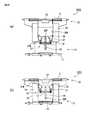
ここで、リンク機構30B1の構造と動作を図10〜図12を用いて説明する。図10(a)、(b)及び図12(a)がディスプレイ部2のスライドとチルト動作が完了した状態を示しており、図11(a)、(b)及び図12(b)がディスプレイ部2のチルト角を最大限変更した状態を示している。なお、図10(b)は図10(a)から一部の部品を削除して内部構造を明らかにしたものであり、図11(b)は図11(a)から一部の部品を削除して内部構造を明らかにしたものである。 Here, the structure and operation of the link mechanism 30B1 will be described with reference to FIGS. FIGS. 10A, 10B, and 12A show a state where the slide and tilt operations of the
図10(a)、(b)及び図12(a)に示すように、リンク機構30B1の本体部側リンク31は、第1ブラケット41に軸支された回転軸11を備える平板状であり、本体部側リンク31の本体部側の面の両側にスライドガイド36が設置されている。スライドガイド36には溝31Mが設けてあり、この溝31Mにディスプレイ部側リンク32の自由端部が挿入されている。そして、ディスプレイ部側リンク32はこの溝31M内を本体部側にスライド移動することができる。ディスプレイ部側リンク32の中央部にはディスプレイ部側リンク32のスライド方向に延びるスリット35が設けられており、本体部側リンク31の先端部側の中央部にはガイドピン35Pが突設されてこのスリット35に嵌め込まれている。スリット35とガイドピン35P及びスライドガイド36により、ディスプレイ部側リンク32は前述の溝31M内を、本体部側に真っ直ぐにスライド移動することができる。 As shown in FIGS. 10A, 10 </ b> B, and 12 </ b> A, the main body side link 31 of the link mechanism 30 </ b> B <b> 1 has a flat plate shape including the
また、スリット35とガイドピン35Pはディスプレイ部側リンク32のスライド量を規制する機能も有する。即ち、ディスプレイ部側リンク32が本体部側リンク31から引き出されていく時、スリット35とガイドピン35Pがないと、ディスプレイ部2を引き起こし過ぎた時に、ディスプレイ部側リンク32の自由端が本体部側リンク31から抜けてしまう。一方、スリット35とガイドピン35Pが設けられていると、ディスプレイ部2を引き起こした時に、ガイドピン35Pがスリット35の端部に当接した時点で、ディスプレイ部2を引き起こせなくなる。この結果、ディスプレイ部2を引き起こした時に、ディスプレイ部側リンク32が本体部側リンク31から抜けることがなくなる。 Further, the
更に、本体部側リンク31とディスプレイ部側リンク32との間には、本体部側リンク31に対するディスプレイ部側リンク32のスライド量を段階的に行えるようにするスライド量調節機構51が設けられている。スライド量調節機構51は、本体部側リンク31のスライドガイド36に設けられた複数のロック溝36M、ディスプレイ部側リンク32に設けられたロックレバー37、ロックローラ38及びロックバネ39を備える。ロック溝36Mはスライドガイド36の対向する縁部に設けられており、ロックローラ38に係合してその位置決めを行う。ロック溝36Mは浅い溝であり、外力の印加によりロックローラ38は容易に1つのロック溝36Mから隣接するロック溝36Mに移動することができる。 Further, a slide
ロックレバー37は2つあり、ディスプレイ部側リンク32の上の、ディスプレイ部側リンク32を二分する線に対して線対称位置に突設された回転軸に、回転自在に取り付けられている。ロックローラ38はロックレバー37の先端部に、回転軸により回転自在に取り付けられており、ロックレバー37の回転により、ロック溝36Mに係合する。ロックバネ39はロックレバー37のロックローラ38と反対側の端部の間に掛け渡された引っ張りバネである。ロックバネ39は、ロックレバー37のロックローラ38が設けられていない端部同士を引き付けることにより、ロックレバー37を回転させてロックローラ38をロック溝36Mに押し付ける。 There are two
本体部1に対するディスプレイ部2のスライドとチルト動作の完了後に、スライド量調節機構51を用いてディスプレイ部2のチルト角度を変更する場合は、ディスプレイ部2の上縁部を持ってディスプレイ部2を寝かせたり起こしたりする操作を行う。すると、スライド量調節機構51のロックローラ38は、それまで係合していたロック溝36Mから抜け出て、1つ隣のロック溝36M、更にはそのまた隣のロック溝36Mへと移動する。図10(a)、(b)及び図12(a)に示す位置から、ロックローラ38が1つずつ隣りのロック溝36Mに移動する毎に、ディスプレイ部側リンク32が本体部側リンク31に収容される。そして、ディスプレイ部側リンク32と本体部側リンク31の重なり部分が増えるにつれて、ディスプレイ部側リンク32のスライド移動量が変化し、ディスプレイ部2のチルト角が変化する。 When the tilt angle of the
ロックバネ39のバネ力は、ディスプレイ部2を指でタッチ操作する時のタッチ力ではロックローラ38がロック溝36Mから抜け出ることがなく、ディスプレイ部2の上縁部を持って動かした時にロック溝36Mから抜け出るように設定する。即ち、ディスプレイ部のチルト角を変更する操作力でロックローラ38がロック溝36Mから抜け出るように設定する。 The spring force of the
図11(a)、(b)及び図12(b)は、図10(a)、(b)及び図12(a)に示す位置から、ロックローラ38が第1回転軸11に最も近いロック溝36Mに移動した場合の状態を示している。即ち、リンク機構30B1が図11(a)、(b)及び図12(b)に示す状態にある時が、情報機器50が図9(b)、(c)に示す状態になった時を示している。このように、リンク機構30B1を備える情報機器50は、閉じ状態からのチルト状態への移行及びチルト状態からのチルト角変更操作をスムーズに行うことができる。 11 (a), 11 (b), and 12 (b) show the lock in which the
図13(a)はディスプレイ部2を本体部1に係止するクローズロック機構8の一実施例の構成を分解して示すものである。クローズロック機構8には中空のケース80があり、ケース80の一端には開口部81がある。また、ケース80の上面には開口部81に連通する上面開口部82がある。このケース80の内部には、開口部81からバネ83が挿入された後に、スライド部材84が挿入される。スライド部材84の両側面にはストッパ85が突設されており、スライド部材84はこのストッパ85が開口部81の縁部に当接するまでケース80の内部に押し込むことができる。更に、スライド部材84のストッパ85から遠い側の端部の上面にはロック突起86が設けられている。ロック突起86は、スライド部材84をケース80内に挿入する時に、上面開口部82内に挿入される。そして、以上のような構成のクローズロック機構8では、スライド部材84のストッパ85が設けられた側の端面がロック解除ボタン87となる。 FIG. 13A shows an exploded configuration of an embodiment of the
図13(b)は図13(a)に示したクローズロック機構8が本体部1の内部に取り付けられ、ディスプレイ部2が本体部1にロックされている状態を示すものであり、スライド部材84の先端部がロック解除ボタン87として本体部1から突出している。本体部1に取り付けられたクローズロック機構8の直上の本体部1の筐体には、ディスプレイ部2の裏面に突設されたロックループ88を通すための孔1Bがある。ロックループ88はロック突起86に係止される係止部材であり、その形状と位置が図9(a)に示される。ディスプレイ部2が本体部1に重なった状態では、ディスプレイ部2にあるロックループ88がクローズロック機構8のロック突起86に係止されているので、ディスプレイ部2は本体部1から開かない。 FIG. 13B shows a state in which the
図13(b)に示した状態において、ロック解除ボタン87が図13(c)に示すように押されると、スライド部材84はストッパ85がケース80に当接するまでケース80の内部に押し込まれ、ロック突起86が上面開口部82内を移動する。ロック突起86の移動により、ロック突起86からロックループ88が外れると、前述したリンク機構30B1により、本体部1に対してディスプレイ部2が開く。ロック解除ボタン87の押圧を止めると、スライド部材84は図13(b)に示した位置まで戻る。この状態でディスプレイ部2が本体部1の上に重ねられた場合は、ロックループ88がロック突起86に当接するが、ロック突起86の上面にはテーパー部があるので、ロックループ88がテーパー部を押してスライド部材84をケース80内に没入させる。この動作により、ロックループ88がロック突起86にロックされた図13(b)に示す状態となる。 In the state shown in FIG. 13B, when the
図13(d)はディスプレイ部2の下端部2Bに設けられた走行ローラ5の一実施例の構成を示すものである。ディスプレイ部2の両側の下端部2Bには凹部2Cが設けられており、この凹部2C内に回転軸6に取り付けられた走行ローラ5がある。走行ローラ5の外周面は凹部2Cから僅かに突出しており、ディスプレイ部2がスライドとチルト動作を開始する時には、走行ローラ5が本体部1の上面に当接する。図13(e)は図13(d)に示した走行ローラ5の回転軸6が、本体部1の上面に突設された回転軸支持部7に係止された状態を示すものである。図13(e)は、例えば、図2(a)、図4(a)及び図7(c)に示した回転軸6と回転軸支持部7との係合状態を部分拡大したものである。回転軸支持部7に係止された回転軸6がディスプレイ部2のチルト角を変更する際の回転中心となる。 FIG. 13 (d) shows a configuration of an embodiment of the traveling
以上説明したリンク機構30B1を取り付けた情報機器50では、図6(a)に示した本体部1にディスプレイ部2を重ねた状態での使用、図6(c)に示した本体部1からディスプレイ部2を起こしてチルトさせた状態での使用が可能である。更に、図9(b)に示した本体部1からディスプレイ部2を起こしてチルトさせた状態からディスプレイ部2のチルト角を変更する使用が可能である。図6(c)と図9(b)に示した状態では、キーボード21が露出しているので、情報機器50に対してキーボード21を用いた入力が可能である。 In the
次に、本体部1とディスプレイ部2の間に取り付ける本出願の第2の実施形態の第2の実施例のリンク機構30B2(以後単にリンク機構30B2と記載する)の構造と動作を図14〜図16を用いて説明する。図14(a)、(b)及び図16(a)がディスプレイ部2のスライドとチルト動作が完了した状態を示しており、リンク機構30B1を説明した図10(a)、(b)及び図12(a)に対応する。また、図15(a)、(b)及び図16(b)がディスプレイ部2のチルト角を最大限変更した状態を示しており、リンク機構30B1を説明した図11(a)、(b)及び図12(b)に対応する。なお、図14(b)は図14(a)から一部の部品を削除して内部構造を明らかにしたものであり、図15(b)は図15(a)から一部の部品を削除して内部構造を明らかにしたものである。 Next, the structure and operation of a link mechanism 30B2 (hereinafter simply referred to as link mechanism 30B2) of the second example of the second embodiment of the present application attached between the
図14(a)、(b)及び図16(a)に示すように、リンク機構30B2の本体部側リンク31は、第1ブラケット41に軸支された回転軸11を備える平板状である。また、第2回転軸22を備えるディスプレイ部側リンク32も平板状であり、ディスプレイ部側リンク32の本体部側の面の両側にスライドガイド36が設置されている。スライドガイド36には溝31Mが設けてあり、この溝31Mに本体部側リンク31の自由端部が挿入されている。そして、本体部側リンク31はこの溝31M内をディスプレイ部側にスライド移動することができる。本体部側リンク31の中央部にはディスプレイ部方向に延びるスリット35が設けられており、ディスプレイ部側リンク32の先端部側の中央部にはガイドピン35Pが突設されてこのスリット35に嵌め込まれている。スリット35とガイドピン35P及びスライドガイド36により、本体部側リンク31は前述の溝31M内を、ディスプレイ部側に真っ直ぐにスライド移動することができる。また、前述のように、スリット35とガイドピン35Pは、本体部側リンク31のスライド量を規制して、ディスプレイ部側リンク32が本体部側リンク31から抜けないようにする機能を有する。 As shown in FIGS. 14A, 14 </ b> B, and 16 </ b> A, the main body side link 31 of the link mechanism 30 </ b> B <b> 2 has a flat plate shape including the
更に、本体部側リンク31とディスプレイ部側リンク32との間には、本体部側リンク31に対するディスプレイ部側リンク32のスライド量を段階的に行えるようにするスライド量調節機構52が設けられている。スライド量調節機構52は、ディスプレイ部側リンク32のスライドガイド36に設けられた複数のロック溝36M、本体部側リンク31に設けられたロックレバー37、ロックローラ38及びロックバネ39を備える。ロック溝36Mはスライドガイド36の対向する縁部に設けられており、ロックローラ38に係合してその位置決めを行う。ロック溝36Mは浅い溝であり、外力の印加によりロックローラ38は容易に1つのロック溝36Mから隣接するロック溝36Mに移動することができる。 Further, a slide
ロックレバー37は2つあり、本体部側リンク31上の、本体部側リンク31を二分する線に対して線対称位置に突設された回転軸に、回転自在に取り付けられている。ロックローラ38はロックレバー37の先端部に、回転軸により回転自在に取り付けられており、ロックレバー37の回転により、ロック溝36Mに係合する。ロックバネ39はロックレバー37のロックローラ38と反対側の端部の間に掛け渡された引っ張りバネである。ロックバネ39は、ロックレバー37のロックローラ38が設けられていない端部同士を引き付けることにより、ロックレバー37を回転させてロックローラ38をロック溝36Mに押し付ける。 There are two
本体部1に対するディスプレイ部2のスライドとチルト動作の完了後に、スライド量調節機構52を用いてディスプレイ部2のチルト角度を変更する場合は、ディスプレイ部2の上縁部を持ってディスプレイ部2を寝かせたり起こしたりする操作を行う。すると、スライド量調節機構52のロックローラ38は、それまで係合していたロック溝36Mから抜け出て、1つ隣のロック溝36M、更にはそのまた隣のロック溝36Mへと移動する。図14(a)、(b)及び図16(a)に示す位置から、ロックローラ38が1つずつ隣りのロック溝36Mに移動する毎に、本体部側リンク31がディスプレイ部側リンク32に収容される。そして、本体部側リンク31とディスプレイ部側リンク32との重なり部分が増えるにつれて、本体部側リンク31のスライド移動量が変化し、ディスプレイ部2のチルト角が変化する。 When the tilt angle of the
ロックバネ39のバネ力は、ディスプレイ部2を指でタッチ操作する時のタッチ力ではロックローラ38がロック溝36Mから抜け出ることがなく、ディスプレイ部2の上縁部を持って動かした時にロック溝36Mから抜け出るように設定する。即ち、ディスプレイ部のチルト角を変更する操作力でロックローラ38がロック溝36Mから抜け出るように設定する。 The spring force of the
図15(a)、(b)及び図16(b)は、図14(a)、(b)及び図16(a)に示す位置から、ロックローラ38が第2回転軸22に最も近いロック溝36Mに移動した場合の状態を示している。即ち、リンク機構30B2が図15(a)、(b)及び図16(b)に示す状態にある時が、情報機器50が図9(b)、(c)に示す状態になった時を示している。このように、リンク機構30B2を備える情報機器50は、閉じ状態からのチルト状態への移行及びチルト状態からのチルト角変更操作をスムーズに行うことができる。 15 (a), 15 (b), and 16 (b) show a lock in which the
更に、本体部1とディスプレイ部2の間に取り付ける本出願の第2の実施形態の第3の実施例のリンク機構30B3(以後単にリンク機構30B3と記載する)の構造と動作を図17〜図19を用いて説明する。図17(a)、(b)及び図19(a)がディスプレイ部2のスライドとチルト動作が完了した状態を示しており、リンク機構30B1を説明した図10(a)、(b)及び図12(a)に対応する。また、図18(a)、(b)及び図19(b)がディスプレイ部2のチルト角を最大限変更した状態を示しており、リンク機構30B1を説明した図11(a)、(b)及び図12(b)に対応する。なお、図17(b)は図17(a)から一部の部品を削除して内部構造を明らかにしたものであり、図18(b)は図18(a)から一部の部品を削除して内部構造を明らかにしたものである。 Further, the structure and operation of the link mechanism 30B3 (hereinafter simply referred to as the link mechanism 30B3) of the third example of the second embodiment of the present application attached between the
図17(a)、(b)及び図19(a)に示すように、リンク機構30B3の本体部側リンク31は、第1ブラケット41に軸支された回転軸11を備える平板状であり、本体部側リンク31の本体部側の面の両側にスライドガイド36が設置されている。スライドガイド36には溝31Mが設けてあり、この溝31Mにディスプレイ部側リンク32の自由端部が挿入されている。そして、ディスプレイ部側リンク32はこの溝31M内を本体部側にスライド移動することができる。ディスプレイ部側リンク32の中央部にはディスプレイ部側リンク32のスライド方向に延びるスリット35が設けられており、本体部側リンク31の先端部側の中央部にはガイドピン35Pが突設されてこのスリット35に嵌め込まれている。スリット35とガイドピン35P及びスライドガイド36により、ディスプレイ部側リンク32は前述の溝31M内を、本体部側に真っ直ぐにスライド移動することができる。また、前述のように、スリット35とガイドピン35Pは、本体部側リンク31のスライド量を規制して、ディスプレイ部側リンク32が本体部側リンク31から抜けないようにする機能を有する。 As shown in FIGS. 17A, 17B, and 19A, the main body side link 31 of the link mechanism 30B3 has a flat plate shape including the
更に、本体部側リンク31とディスプレイ部側リンク32との間には、本体部側リンク31に対するディスプレイ部側リンク32のスライド量を連続的に行えるようにするスライド量調節機構53が設けられている。スライド量調節機構53は、本体部側リンク31のスライドガイド36に設けられた摺動面36S、ディスプレイ部側リンク32に設けられたロックレバー37、ロックパッド40及びロックバネ39を備える。摺動面36Sはスライドガイド36の対向する縁部に設けられており、ロックパッド40に係合してその位置決めを行う。摺動面36Sと、ロックパッド40の摺動面36Sとの当接面は所定の摩擦係数を備えた面であり、所定の外力が印加されると摺動面36Sとロックパッド40とが摺動するようになっている。 Further, a slide
ロックレバー37は2つあり、ディスプレイ部側リンク32の上の、ディスプレイ部側リンク32を二分する線に対して線対称位置に突設された回転軸に、回転自在に取り付けられている。ロックパッド40はロックレバー37の先端部に搖動可能に取り付けられており、ロックレバー37の回転により、摺動面36Sに押し付けられる。ロックバネ39はロックレバー37のロックパッド40と反対側の端部の間に掛け渡された引っ張りバネである。ロックバネ39は、ロックレバー37のロックパッド40が設けられていない端部同士を引き付けることにより、ロックレバー37を回転させてロックパッド40を摺動面36Sに押し付ける。 There are two
本体部1に対するディスプレイ部2のスライドとチルト動作の完了後に、スライド量調節機構53を用いてディスプレイ部2のチルト角度を変更する場合は、ディスプレイ部2の上縁部を持ってディスプレイ部2を寝かせたり起こしたりする操作を行う。すると、スライド量調節機構53のロックパッド40が摺動面36S上を移動する。図17(a)、(b)及び図19(a)に示す位置から、ロックパッド40が摺動面36Sの上を摺動して移動する毎に、ディスプレイ部側リンク32が本体部側リンク31に収容される。そして、ディスプレイ部側リンク32と本体部側リンク31の重なり部分が増えるにつれて、ディスプレイ部側リンク32のスライド移動量が変化し、ディスプレイ部2のチルト角が変化する。 When the tilt angle of the
ロックバネ39のバネ力は、ディスプレイ部2を指でタッチ操作する時のタッチ力ではロックパッド40が摺動面36Sの上を摺動することがなく、ディスプレイ部2の上縁部を持って動かした時に摺動面36Sに対して摺動するように設定する。即ち、ディスプレイ部のチルト角を変更する操作力でロックパッド40が摺動面36Sの上を摺動するように設定する。 The spring force of the
なお、リンク機構30B3では、ダンパ機構70の構成が、他の実施例と異なっている。リンク機構30B3におけるダンパ機構70は、第1回転軸11に取り付けられた第1歯車76と、第1歯車76に歯合する第2歯車77と、第2歯車77の回転速度を弱めるダンパ75とを備えている。ダンパ75の内部にはオイルが充填されており、このオイルによって第2歯車77が取り付けられているダンパ75の回転軸の回転速度を弱めるようになっている。ダンパ機構70はこの形態以外にも考えられ、形態は特に限定されるものではない。 In the link mechanism 30B3, the configuration of the
図18(a)、(b)及び図19(b)は、図17(a)、(b)及び図19(a)に示す位置から、ロックパッド40が最も第1回転軸11に近い摺動面36S側に移動した場合の状態を示している。即ち、リンク機構30B3が図18(a)、(b)及び図19(b)に示す状態にある時が、情報機器50が図9(b)、(c)に示す状態になった時を示している。このように、リンク機構30B3を備える情報機器50は、閉じ状態からチルト状態への移行をスムーズに行うことができ、更にチルト状態からのチルト角変更操作をフリーストップで行うことができる。 18 (a), 18 (b), and 19 (b) show the sliding state where the
次に、本体部1とディスプレイ部2の間に取り付ける本出願の第2の実施形態の第4の実施例のリンク機構30B4(以後単にリンク機構30B4と記載する)の構造と動作を図20〜図22を用いて説明する。図20(a)、(b)及び図22(a)がディスプレイ部2のスライドとチルト動作が完了した状態を示しており、リンク機構30B1を説明した図10(a)、(b)及び図12(a)に対応する。また、図21(a)、(b)及び図22(b)がディスプレイ部2のチルト角を最大限変更した状態を示しており、リンク機構30B1を説明した図11(a)、(b)及び図12(b)に対応する。なお、図20(b)は図20(a)から一部の部品を削除して内部構造を明らかにしたものであり、図21(b)は図21(a)から一部の部品を削除して内部構造を明らかにしたものである。 Next, the structure and operation of the link mechanism 30B4 (hereinafter simply referred to as the link mechanism 30B4) of the fourth example of the second embodiment of the present application attached between the
図20(a)、(b)及び図22(a)に示すように、リンク機構30B4の本体部側リンク31は、第1ブラケット41に軸支された回転軸11を備えた平行状であり、その本体部側の面にスライドガイド36が設置されている。スライドガイド36には溝31Mが設けられている。ディスプレイ部側リンク32は第2回転軸を一端に備える平板状をしており、他端が前述の溝31Mに挿入されている。そして、ディスプレイ部側リンク32はこの溝31M内を本体部側にスライド移動することができる。 As shown in FIGS. 20A, 20 </ b> B, and 22 </ b> A, the main body side link 31 of the link mechanism 30 </ b> B <b> 4 has a parallel shape including the
なお、リンク機構30B4には、前述のようは、本体部側リンク31のスライド量を規制して、ディスプレイ部側リンク32が本体部側リンク31から抜けないようにする機能を有するスリット35とガイドピン35Pがない。その代わりに、リンク機構30B4には、図20(b)、図21(b)に示すようにディスプレイ部側リンク32の自由端部に、ディスプレイ部側リンク32の最大スライド量を規制する突起32Sが設けられている。更に、スライドガイド36の溝31M内には、図示は省略するが、突起32Sの移動を係止する壁が設けられている。リンク機構30B4では、ディスプレイ部2が引き起こされ、ディスプレイ部側リンク32が本体部側リンク31から引き出されていく時に、突起32Sが壁に当接するので、ディスプレイ部側リンク32の本体部側リンク31から抜けることがない。 As described above, the link mechanism 30B4 includes a
更に、本体部側リンク31とディスプレイ部側リンク32との間には、本体部側リンク31に対するディスプレイ部側リンク32のスライド量を連続的に行えるようにするスライド量調節機構54が設けられている。スライド量調節機構54は、本体部側リンク31のスライドガイド36の溝31Mの奥に設けられた抑えバネ34を備えている。抑えバネ34は2つのスライドガイド36の両方に設けられている。抑えバネ34により、ディスプレイ部側リンク32の平板部は両側から抑え付けられており、容易に移動しないようになっている。そして、ディスプレイ部側リンク32に所定の外力が印加されると、抑えバネ34による付勢力に抗してディスプレイ部側リンク32が移動するようになっている。 Further, a slide
本体部1に対するディスプレイ部2のスライドとチルト動作の完了後に、スライド量調節機構54を用いてディスプレイ部2のチルト角度を変更する場合は、ディスプレイ部2の上縁部を持ってディスプレイ部2を寝かせたり起こしたりする操作を行う。すると、スライド量調節機構54の抑えバネ34による付勢力に抗してディスプレイ部側リンク32が移動する。図20(a)、(b)及び図22(a)に示す位置から、ディスプレイ部側リンク32が抑えバネ34による付勢力に抗して移動する毎に、ディスプレイ部側リンク32が本体部側リンク31に収容される。そして、ディスプレイ部側リンク32と本体部側リンク31の重なり量が増えるにつれて、ディスプレイ部側リンク32のスライド移動量が変化し、ディスプレイ部2のチルト角が変化する。 When the tilt angle of the
抑えバネ34のバネ力は、ディスプレイ部2を指でタッチ操作する時のタッチ力ではディスプレイ部側リンク32が抑えバネ34による付勢力に抗して移動することがないように設定する。一方、抑えバネ34のバネ力は、ディスプレイ部2の上端部を持って動かした時には、ディスプレイ部側リンク32が抑えバネ34による付勢力に抗して移動するように設定する。即ち、ディスプレイ部のチルト角を変更する操作力でディスプレイ部側リンク32が抑えバネ34による付勢力に抗して移動するように設定する。 The spring force of the restraining
図21(a)、(b)及び図22(b)は、図20(a)、(b)及び図22(a)に示す位置から、ディスプレイ部側リンク32が最も第1回転軸11に近い位置に移動した場合の状態を示している。即ち、リンク機構30B4が図21(a)、(b)及び図22(b)に示す状態にある時が、情報機器50が図9(b)、(c)に示す状態になった時を示している。このように、リンク機構30B4を備える情報機器50は、閉じ状態からチルト状態への移行をスムーズに行うことができ、更に、チルト状態からのチルト角変更操作をフリーストップで行うことができる。 21 (a), (b) and FIG. 22 (b) show that the display unit side link 32 is the most at the first
図23(a)は、本出願の第2の実施形態の第5の実施例のリンク機構30B5(以後単にリンク機構30B5と記載する)を備えた情報機器50において、ディスプレイ部2のチルト動作が完了した状態を背面側から見た斜視図である。リンク機構30B5を除く部分の情報機器50の構成は、リンク機構30B1〜30B4を備えた情報機器50と同じである。リンク機構30B5にある本体部側リンク31は、本体部1の後ろ側でブラケット41に回転支持された第1回転軸を備えたリンク基部31Kと、リンク基部31Kに所定間隔を隔てて回転自在に取り付けられた2本のリンクアーム31Aとを備えている。また、リンク機構30B5にあるディスプレイ部側リンク32は、第2回転軸22に回転支持されたリンク基部32Kと、リンク基部32Kに所定間隔を隔てて回転自在に取り付けられた2本のリンクアーム32Aとを備えている。 FIG. 23A shows a tilt operation of the
2本のリンクアーム31Aとリンクアーム32Aの他端は、第3回転軸33によって回転自在に結合されている。そして、2本のリンクアーム31Aのリンク基部31Kへの取付間隔と、2本のリンクアーム32Aのリンク基部32Kへの取付間隔は同じである。従って、第3回転軸33で連結された2本のリンクアーム31A、32Aは、リンク基部31Kとリンク基部32Kの間に平行に配設されている。 The other ends of the two
更に、リンク機構30B5におけるリンクアーム31Aとリンクアーム32Aの結合部は、第3回転軸33によって結合されているが、この結合部は図示しないロック機構によって通常は回転しないように固定されている。従って、リンク機構30B5におけるリンク基部31Kとリンク基部32Kの間の距離は、ロック機構のロックを解除しない限り一定である。ディスプレイ部2の下端部2Bにはチルト回転軸に取り付けられた走行ローラ5があり、本体部1の上面には走行ローラ5が本体部1の面上を移動して来た時にチルト回転軸の移動を係止する回転軸支持部7がある。よって、前述の実施例と同様に、本体部1に対してディスプレイ部2の上端部2Tを引き上げると、リンク機構30B5によって本体部1に対してディスプレイ部2がスライドとチルト動作を行い、ディスプレイ部2がチルトする。ディスプレイ部2のチルト動作において、リンク機構30B5のリンク基部31Kとリンク基部32Kの間の距離は変わらない。 Further, the connecting portion of the
図23(a)に示す状態で、リンクアーム31Aとリンクアーム32Aの係合部に設けられたロック機構のロックを外すと、リンクアーム31Aとリンクアーム32Aは第3回転軸33間の距離が広がる方向に変形可能となる。よって、この状態でディスプレイ部2の上端部2Tを後ろ側に押すと、第3回転軸33間の距離が広がり、リンクアーム31Aとリンクアーム32Aは中折れし、パンタグラフを畳むように変形する。この結果、リンク基部31Kとリンク基部32Kの間の距離が縮まり、図23(b)に示すように、ディスプレイ部2がチルト回転軸を中心にして回転し、チルト角度を変更できる。この場合、第3回転軸33を備える結合部に本体部側リンク31に対するディスプレイ部側リンク32の回転を抑える機構や回転を段階的に行わせる機構を設けておけば良い。 In the state shown in FIG. 23A, when the lock mechanism provided at the engaging portion between the
以上のように構成されたリンク機構を本体部とディスプレイ部との間に備えた情報機器には、以下のような効果がある。
(1)ディスプレイ部が本体部に重なった状態からチルトした状態まで1段階の操作で変化するため、操作感がスムーズである。
(2)チルト状態からさらにチルト角を変更できるので、利用者がディスプレイを見易い角度に設定できて使い勝手が向上する。
(3)ディスプレイ部が本体部に重なった状態からチルトした状態まで変化する際に、ディスプレイ部が本体部の上方空間から外に出ないので、狭い空間で操作できる。
(4)チルト状態からクローズ状態へ戻す時も1段階の操作で変化するので操作感がスムーズである。
(5)チルト状態から更にチルト角を変更する際に、ディスプレイ部の下端部が一定の位置に保持されているので、本体部のキーボードをディスプレイ部の下端近くまで配置することができ、キーボードの操作面を広くできてキーボードの操作性が向上する。
(6)第2の実施形態のリンク機構では、ディスプレイ部の裏側をリンクで支持しているためチルト状態でタッチパネルを操作した時にディスプレイ部がぐらつかず、タッチパネル操作時にディスプレイ部に剛性感があってタッチ操作を安定にできる。The information device provided with the link mechanism configured as described above between the main body portion and the display portion has the following effects.
(1) Since the display unit changes from a state where the display unit is overlapped with the main body unit to a state where the display unit is tilted, the operation feeling is smooth.
(2) Since the tilt angle can be further changed from the tilt state, the user can set the angle so that the user can easily see the display, and the usability is improved.
(3) When the display unit changes from a state where it overlaps the main body unit to a tilted state, the display unit does not go out of the upper space of the main body unit, so that it can be operated in a narrow space.
(4) Even when returning from the tilted state to the closed state, the operational feeling is smooth because it is changed by a one-step operation.
(5) When the tilt angle is further changed from the tilted state, the lower end portion of the display unit is held at a fixed position, so that the keyboard of the main body unit can be arranged near the lower end of the display unit. The operation surface can be widened and the operability of the keyboard is improved.
(6) In the link mechanism of the second embodiment, since the back side of the display unit is supported by the link, the display unit does not wobble when the touch panel is operated in the tilted state, and the display unit has a sense of rigidity when the touch panel is operated. Touch operation can be stabilized.
以上、本出願を特にその好ましい実施の実施形態を参照して詳細に説明した。本出願の容易な理解のために、本出願の具体的な実施形態を以下に付記する。 The present application has been described in detail with particular reference to preferred embodiments thereof. For easy understanding of the present application, specific embodiments of the present application are appended below.
(付記1) 情報機器の本体部に重なるディスプレイ部の上端部を引き上げ、下端部を前記本体部上でスライドさせて、前記ディスプレイ部を前記本体部の上でチルトさせた後に、前記ディスプレイ部のチルト角度を変更することが可能な情報機器のチルト機構であって、
前記ディスプレイ部の下端部に設けられた走行ローラと、
前記本体部の上面に設けられ、前記走行ローラの回転軸を回転可能に係止する回転軸支持部と、
前記本体部に一端が第1回転軸によって回転自在に取り付けられ、他端に第1係合部を備えた第1リンクと、
前記ディスプレイ部に一端が第2回転軸によって回転自在に取り付けられ、他端に第2係合部を備えた第2リンクと、
前記第1係合部と第2係合部とを係合させ、前記ディスプレイ部が前記本体部に重なった状態から引き上げられて前記ローラの回転軸が前記回転軸支持部に係止されるまでは、前記第1係合部と前記第2係合部の係合状態を固定し、前記ローラの回転軸が前記回転軸支持部に係止された後は、前記第1係合部と前記第2係合部の固定係合状態を解除して前記第1回転軸と前記第2回転軸間の距離が短くなるように変形可能なリンク機構とを備えることを特徴とする情報機器のチルト機構。
(付記2) 前記第1回転軸と前記第2回転軸は、前記第1筐体と前記第2筐体の側面に設けられていることを特徴とする付記1に記載の情報機器のチルト機構。
(付記3) 前記第1回転軸は前記第1筐体の上面に、前記第2回転軸は前記第2筐体の裏面に設けられていることを特徴とする付記1に記載の情報機器のチルト機構。
(付記4) 前記第1リンクの第1係合部は溝を備えており、前記第2リンクの第2係合部は前記溝の中をスライド可能に前記溝に挿入されていることを特徴とする付記2に記載の情報機器のチルト機構。
(付記5) 前記第1リンクの第1係合部と、前記第2リンクの第2係合部とは、第3回転軸によって回転可能に結合されていることを特徴とする付記2に記載の情報機器のチルト機構。(Supplementary Note 1) After the upper end of the display unit that overlaps the main unit of the information device is pulled up, the lower end is slid on the main unit, and the display unit is tilted on the main unit. A tilt mechanism of an information device capable of changing a tilt angle,
A traveling roller provided at the lower end of the display unit;
A rotation shaft support portion provided on the upper surface of the main body portion and rotatably locking the rotation shaft of the traveling roller;
A first link having one end rotatably attached to the main body portion by a first rotating shaft and a first engaging portion at the other end;
A second link having one end rotatably attached to the display unit by a second rotating shaft and having a second engaging portion at the other end;
The first engaging portion and the second engaging portion are engaged, and the display portion is pulled up from the state where it overlaps the main body portion, and the rotation shaft of the roller is locked to the rotation shaft support portion. After the engagement state of the first engagement portion and the second engagement portion is fixed and the rotation shaft of the roller is locked to the rotation shaft support portion, the first engagement portion and the second engagement portion are fixed. A tilt mechanism for an information device, comprising: a link mechanism that can be deformed so that a distance between the first rotating shaft and the second rotating shaft is shortened by releasing a fixed engaging state of the second engaging portion. mechanism.
(Additional remark 2) The tilt mechanism of the information apparatus according to
(Supplementary note 3) The information device according to
(Additional remark 4) The 1st engaging part of the said 1st link is provided with the groove | channel, The 2nd engaging part of the said 2nd link is inserted in the said groove | channel so that a slide is possible in the said groove | channel. The tilt mechanism of the information equipment according to
(Additional remark 5) The 1st engaging part of the said 1st link and the 2nd engaging part of the said 2nd link are couple | bonded so that rotation by the 3rd rotating shaft is possible, The
(付記6) 前記第1係合部と前記第2係合部の前記第3回転軸による結合部には、前記第1リンクと前記第2リンクとを一直線上に保持するロック機構が設けられていることを特徴とする付記5に記載の情報機器のチルト機構。
(付記7) 前記第2回転軸は、前記第2回転軸が前記第1筐体から離れる方向に前記第2リンクを付勢する付勢手段を備えており、
前記第1筐体と前記第2筐体の間に、前記第1筐体に前記第2筐体が重なった状態で、前記第2筐体を前記第1筐体上に固定するロック機構が設けられ、
前記ロック機構のロックを解除すると前記付勢手段により、前記第2筐体が第1筐体から自動的にチルトすることを特徴とする付記3に記載の情報機器のチルト機構。
(付記8) 前記第1筐体側に、前記第1リンクが前記第1回転軸を中心にして回転移動する際の回転速度を弱めるダンパ機構が設けられていることを特徴とする付記7に記載の情報機器のチルト機構。
(付記9) 前記ダンパ機構が、前記第1回転軸に取り付けられたダンパカムと、前記ダンパカムの外周面に当接する接触子と、前記接触子の移動速度を弱めるダンパとを備えることを特徴とする付記8に記載の情報機器のチルト機構。
(付記10) 前記ダンパ機構が、前記第1回転軸に取り付けられた第1歯車と、前記第1歯車に歯合する第2歯車と、前記第2歯車の回転速度を弱めるダンパとを備えることを特徴とする付記8に記載の情報機器のチルト機構。(Supplementary Note 6) A lock mechanism that holds the first link and the second link in a straight line is provided at a coupling portion of the first engagement portion and the second engagement portion that is formed by the third rotation shaft. 6. A tilt mechanism for an information device according to
(Supplementary Note 7) The second rotation shaft includes a biasing unit that biases the second link in a direction in which the second rotation shaft is separated from the first housing.
A locking mechanism for fixing the second housing on the first housing in a state where the second housing overlaps the first housing between the first housing and the second housing. Provided,
4. The tilt mechanism of information equipment according to claim 3, wherein when the lock mechanism is unlocked, the biasing means automatically tilts the second casing from the first casing.
(Supplementary note 8) The
(Additional remark 9) The said damper mechanism is provided with the damper cam attached to the said 1st rotating shaft, the contactor contact | abutted on the outer peripheral surface of the said damper cam, and the damper which weakens the moving speed of the said contactor, It is characterized by the above-mentioned. The tilt mechanism of the information device according to
(Additional remark 10) The said damper mechanism is equipped with the 1st gear attached to the said 1st rotating shaft, the 2nd gear meshing | engaged with the said 1st gear, and the damper which weakens the rotational speed of the said 2nd gear. 9. A tilt mechanism for an information device according to
(付記11) 前記第1リンク及び前記第2リンクが平板状であり、
前記第1リンクの幅方向の両側部にはスライドガイドが設けられ、
前記スライドガイドの対向縁部には前記第2リンクを挿入する溝と、前記スライドガイドの長手方向に連続して設けられたロック溝が設けられ、
前記第2リンクの前記第2係合部は前記溝に挿入され、前記第2リンクの自由端部側には、前記ロック溝に係合するロックローラを備えた一対のロックレバーが回動可能に取り付けられており、前記ロックレバーはロックバネの付勢力により常時前記ロックローラを前記ロック溝に係合させていることを特徴とする付記7から10の何れかに記載の情報機器のチルト機構。
(付記12) 前記第1リンク及び前記第2リンクが平板状であり、
前記第2リンクの幅方向の両側部にはスライドガイドが設けられ、
前記スライドガイドの対向縁部には前記第1リンクを挿入する溝と、前記スライドガイドの長手方向に連続して設けられたロック溝が設けられ、
前記第1リンクの前記第1係合部は前記溝に挿入され、前記第1リンクの自由端部側には、前記ロック溝に係合するロックローラを備えた一対のロックレバーが回動可能に取り付けられており、前記ロックレバーはロックバネの付勢力により常時前記ロックローラを前記ロック溝に係合させていることを特徴とする付記7から10の何れかに記載の情報機器のチルト機構。
(付記13) 前記第1リンク及び前記第2リンクが平板状であり、
前記第1リンクの幅方向の両側部にはスライドガイドが設けられ、
前記スライドガイドの対向縁部には前記第2リンクを挿入する溝と、前記スライドガイドの長手方向に平行に設けられた摺動面が設けられ、
前記第2リンクの前記第2係合部は前記溝に挿入され、前記第2リンクの自由端部側には、前記摺動面に当接するロックパッドを備えた一対のロックレバーが回動可能に取り付けられており、前記ロックレバーはロックバネの付勢力により常時前記ロックパッドを前記摺動面に押し付けていることを特徴とする付記7から10の何れかに記載の情報機器のチルト機構。
(付記14) 前記第1リンク及び前記第2リンクが平板状であり、
前記第1リンクの幅方向の両側部にはスライドガイドが設けられ、
前記スライドガイドの対向縁部には前記第2リンクを挿入する溝が設けられ、
前記第2リンクの前記第2係合部は前記溝に挿入され、前記スライドガイドの内部の前記第2リンクの縁部に対向する部分には、前記第2リンクの縁部の移動を抑制する抑えバネが設けられていることを特徴とする付記7から10の何れかに記載の情報機器のチルト機構。
(付記15) 前記第1リンクが、前記第1回転軸11を備えた第1リンク基部と、一端が前記第1リンク基部に所定間隔を隔てて回転可能に取り付けられ、他端に第1係合部を備える2本の第1リンクアームを備え、
前記第2リンクが、前記第2回転軸を備えた第2リンク基部と、一端が前記第2リンク基部に所定間隔を隔てて回転可能に取り付けられ、他端に第2係合部を備える2本の第2リンクアームを備え、
前記第1係合部と前記第2係合部とは、第3回転軸によって回転可能に結合され、
前記第1係合部と前記第2係合部の前記第3回転軸による結合部には、前記第1リンクと前記第2リンクとを一直線上に保持するロック機構が設けられていることを特徴とする付記7から10の何れかに記載の情報機器のチルト機構。(Additional remark 11) The said 1st link and the said 2nd link are flat form,
Slide guides are provided on both sides in the width direction of the first link,
The opposite edge of the slide guide is provided with a groove for inserting the second link and a lock groove provided continuously in the longitudinal direction of the slide guide,
The second engagement portion of the second link is inserted into the groove, and a pair of lock levers having a lock roller that engages with the lock groove is rotatable on the free end side of the second link. 11. The tilt mechanism for an information device according to any one of
(Additional remark 12) The said 1st link and the said 2nd link are flat form,
Slide guides are provided on both sides in the width direction of the second link,
The opposite edge of the slide guide is provided with a groove for inserting the first link and a lock groove provided continuously in the longitudinal direction of the slide guide,
The first engagement portion of the first link is inserted into the groove, and a pair of lock levers having a lock roller that engages with the lock groove is rotatable on the free end portion side of the first link. 11. The tilt mechanism for an information device according to any one of
(Additional remark 13) The said 1st link and the said 2nd link are flat form,
Slide guides are provided on both sides in the width direction of the first link,
A groove for inserting the second link and a sliding surface provided in parallel to the longitudinal direction of the slide guide are provided on the opposite edge of the slide guide,
The second engagement portion of the second link is inserted into the groove, and a pair of lock levers provided with a lock pad abutting against the sliding surface are rotatable on the free end side of the second link. 11. The tilt mechanism for an information device according to any one of
(Additional remark 14) The said 1st link and the said 2nd link are flat form,
Slide guides are provided on both sides in the width direction of the first link,
A groove for inserting the second link is provided at the opposite edge of the slide guide,
The second engaging portion of the second link is inserted into the groove, and the movement of the edge of the second link is suppressed at a portion facing the edge of the second link inside the slide guide. The tilt mechanism for an information device according to any one of
(Supplementary Note 15) The first link includes a first link base portion including the first
The second link includes a second link base having the second rotation shaft, one end rotatably attached to the second link base at a predetermined interval, and the other end having a second engaging portion. A second link arm of the book,
The first engaging portion and the second engaging portion are rotatably coupled by a third rotating shaft,
A coupling mechanism for holding the first link and the second link in a straight line is provided at a coupling portion of the first engagement portion and the second engagement portion by the third rotation shaft. 11. A tilt mechanism for an information device according to any one of
1 第1筐体(本体部)
2 第2筐体(ディスプレイ部)
5 走行ローラ
6 チルト回転軸
7 回転軸支持部
8 クローズロック機構
9 アシストバネ
11 第1回転軸
22 第2回転軸
30A1、30A2 第1の形態のリンク機構
30B1〜30B5 第2の形態のリンク機構
31 第1リンク(本体部側リンク)
32 第2リンク(ディスプレイ部側リンク)
33 第3回転軸
36 スライドガイド
37 ロックレバー
38 ロックローラ
39 ロックバネ
50 情報機器
51〜54 スライド量調節機構
70 ダンパ機構1 First housing (main body)
2 Second housing (display unit)
DESCRIPTION OF
32 Second link (link on display side)
33 Third
Claims (5)
Translated fromJapanese前記ディスプレイ部の下端部に設けられた走行ローラと、
前記本体部の上面に設けられ、前記走行ローラの回転軸を回転可能に係止する回転軸支持部と、
前記本体部に一端が第1回転軸によって回転自在に取り付けられ、他端に第1係合部を備えた第1リンクと、
前記ディスプレイ部に一端が第2回転軸によって回転自在に取り付けられ、他端に第2係合部を備えた第2リンクと、
前記第1係合部と第2係合部とを係合させ、前記ディスプレイ部が前記本体部に重なった状態から引き上げられて前記ローラの回転軸が前記回転軸支持部に係止されるまでは、前記第1係合部と前記第2係合部の係合状態を固定し、前記ローラの回転軸が前記回転軸支持部に係止された後は、前記第1係合部と前記第2係合部の固定係合状態を解除して前記第1回転軸と前記第2回転軸間の距離が短くなるように変形可能なリンク機構とを備えることを特徴とする情報機器のチルト機構。Pull up the upper end of the display unit that overlaps the main unit of the information device, slide the lower end on the main unit, tilt the display unit on the main unit, and then change the tilt angle of the display unit A tilt mechanism of an information device capable of
A traveling roller provided at the lower end of the display unit;
A rotation shaft support portion provided on the upper surface of the main body portion and rotatably locking the rotation shaft of the traveling roller;
A first link having one end rotatably attached to the main body portion by a first rotating shaft and a first engaging portion at the other end;
A second link having one end rotatably attached to the display unit by a second rotating shaft and having a second engaging portion at the other end;
The first engaging portion and the second engaging portion are engaged, and the display portion is pulled up from the state where it overlaps the main body portion, and the rotation shaft of the roller is locked to the rotation shaft support portion. After the engagement state of the first engagement portion and the second engagement portion is fixed and the rotation shaft of the roller is locked to the rotation shaft support portion, the first engagement portion and the second engagement portion are fixed. A tilt mechanism for an information device, comprising: a link mechanism that can be deformed so that a distance between the first rotating shaft and the second rotating shaft is shortened by releasing a fixed engaging state of the second engaging portion. mechanism.
前記第1筐体と前記第2筐体の間に、前記第1筐体に前記第2筐体が重なった状態で、前記第2筐体を前記第1筐体上に固定するロック機構が設けられ、
前記ロック機構のロックを解除すると前記付勢手段により、前記第2筐体が第1筐体から自動的にチルトすることを特徴とする請求項2に記載の情報機器のチルト機構。The second rotating shaft includes a biasing unit that biases the second link in a direction in which the second rotating shaft is separated from the first housing.
A locking mechanism for fixing the second housing on the first housing in a state where the second housing overlaps the first housing between the first housing and the second housing. Provided,
3. The tilt mechanism for an information device according to claim 2, wherein when the lock mechanism is unlocked, the second casing is automatically tilted from the first casing by the biasing means.
前記第1リンクの幅方向の両側部にはスライドガイドが設けられ、
前記スライドガイドの対向縁部には前記第2リンクを挿入する溝と、前記スライドガイドの長手方向に連続して設けられたロック溝が設けられ、
前記第2リンクの前記第2係合部は前記溝に挿入され、前記第2リンクの自由端部側には、前記ロック溝に係合するロックローラを備えた一対のロックレバーが回動可能に取り付けられており、前記ロックレバーはロックバネの付勢力により常時前記ロックローラを前記ロック溝に係合させていることを特徴とする請求項2又は3に記載の情報機器のチルト機構。The first link and the second link are flat;
Slide guides are provided on both sides in the width direction of the first link,
The opposite edge of the slide guide is provided with a groove for inserting the second link and a lock groove provided continuously in the longitudinal direction of the slide guide,
The second engagement portion of the second link is inserted into the groove, and a pair of lock levers having a lock roller that engages with the lock groove is rotatable on the free end side of the second link. 4. The tilt mechanism for an information device according to claim 2, wherein the lock lever constantly engages the lock roller with the lock groove by an urging force of a lock spring.
前記第2リンクが、前記第2回転軸を備えた第2リンク基部と、一端が前記第2リンク基部に所定間隔を隔てて回転可能に取り付けられ、他端に第2係合部を備える2本の第2リンクアームを備え、
前記第1係合部と前記第2係合部とは、第3回転軸によって回転可能に結合され、
前記第1係合部と前記第2係合部の前記第3回転軸による結合部には、前記第1リンクと前記第2リンクとを一直線上に保持するロック機構が設けられていることを特徴とする請求項2から4の何れか1項に記載の情報機器のチルト機構。The first link is provided with a first link base having the first rotation shaft 11, one end rotatably attached to the first link base with a predetermined interval, and the other end with a first engagement portion. With two first link arms,
The second link includes a second link base having the second rotation shaft, one end rotatably attached to the second link base at a predetermined interval, and the other end having a second engaging portion. A second link arm of the book,
The first engaging portion and the second engaging portion are rotatably coupled by a third rotating shaft,
A coupling mechanism for holding the first link and the second link in a straight line is provided at a coupling portion of the first engagement portion and the second engagement portion by the third rotation shaft. The tilt mechanism for an information device according to claim 2, wherein the tilt mechanism is an information device.
Priority Applications (5)
| Application Number | Priority Date | Filing Date | Title |
|---|---|---|---|
| JP2013018514AJP6094237B2 (en) | 2013-02-01 | 2013-02-01 | IT equipment tilt mechanism |
| US14/156,882US9134755B2 (en) | 2013-02-01 | 2014-01-16 | Tilt mechanism for information device |
| TW103102301ATWI550384B (en) | 2013-02-01 | 2014-01-22 | Tilt mechanism for information device |
| EP14152405.8AEP2762993B1 (en) | 2013-02-01 | 2014-01-24 | Tilt mechanism for information device |
| CN201410039738.9ACN103970207B (en) | 2013-02-01 | 2014-01-27 | Tilt mechanism for information device |
Applications Claiming Priority (1)
| Application Number | Priority Date | Filing Date | Title |
|---|---|---|---|
| JP2013018514AJP6094237B2 (en) | 2013-02-01 | 2013-02-01 | IT equipment tilt mechanism |
Publications (2)
| Publication Number | Publication Date |
|---|---|
| JP2014149719Atrue JP2014149719A (en) | 2014-08-21 |
| JP6094237B2 JP6094237B2 (en) | 2017-03-15 |
Family
ID=49998126
Family Applications (1)
| Application Number | Title | Priority Date | Filing Date |
|---|---|---|---|
| JP2013018514AExpired - Fee RelatedJP6094237B2 (en) | 2013-02-01 | 2013-02-01 | IT equipment tilt mechanism |
Country Status (5)
| Country | Link |
|---|---|
| US (1) | US9134755B2 (en) |
| EP (1) | EP2762993B1 (en) |
| JP (1) | JP6094237B2 (en) |
| CN (1) | CN103970207B (en) |
| TW (1) | TWI550384B (en) |
Cited By (1)
| Publication number | Priority date | Publication date | Assignee | Title |
|---|---|---|---|---|
| JP2016170540A (en)* | 2015-03-11 | 2016-09-23 | Necパーソナルコンピュータ株式会社 | Information processing apparatus |
Families Citing this family (32)
| Publication number | Priority date | Publication date | Assignee | Title |
|---|---|---|---|---|
| JP6065537B2 (en)* | 2012-11-16 | 2017-01-25 | 富士通株式会社 | Information device and information device link mechanism |
| KR20150077667A (en)* | 2013-12-30 | 2015-07-08 | 삼성전자주식회사 | Electronic apparatus, method for controlling thereof and computer-readable recording medium |
| US9405325B2 (en)* | 2014-01-03 | 2016-08-02 | Lg Electronics Inc. | Portable terminal |
| JP6418550B2 (en)* | 2014-08-15 | 2018-11-07 | 富士通クライアントコンピューティング株式会社 | Electronic equipment and arm device |
| CN106292861B (en)* | 2015-06-10 | 2019-04-26 | 联想(北京)有限公司 | Electronic equipment and its control method |
| DE102015220813A1 (en)* | 2015-10-23 | 2017-04-27 | Andreas Seibold | Device for panning a virtual reality display and method for displaying a virtual reality scene |
| US10159158B2 (en) | 2016-04-14 | 2018-12-18 | Microsoft Technology Licensing, Llc | Device with a rotatable display |
| US10996710B2 (en) | 2016-04-14 | 2021-05-04 | Microsoft Technology Licensing, Llc | Device with a rotatable display |
| US9936593B2 (en) | 2016-04-14 | 2018-04-03 | Microsoft Technology Licensing, Llc | Device with a rotatable display |
| US10345851B2 (en) | 2016-04-14 | 2019-07-09 | Microsoft Technology Licensing, Llc | Device with a rotatable display |
| US10172248B1 (en)* | 2016-04-14 | 2019-01-01 | Microsoft Technology Licensing, Llc | Device with a rotatable display |
| US10999944B2 (en) | 2016-04-26 | 2021-05-04 | Microsoft Technology Licensing, Llc | Structural device cover |
| US9946309B2 (en) | 2016-06-10 | 2018-04-17 | Microsoft Technology Licensing, Llc | Device wiring |
| US10221898B2 (en) | 2016-07-01 | 2019-03-05 | Microsoft Technology Licensing, Llc | Hinge clutch |
| US10871016B2 (en) | 2017-01-17 | 2020-12-22 | Huawei Technologies Co., Ltd. | Protective case for tablet computer and two-in-one computer |
| EP3627805B1 (en)* | 2017-05-17 | 2025-04-09 | Guangdong Oppo Mobile Telecommunications Corp., Ltd. | Foldable mobile terminal |
| EP3627803B1 (en) | 2017-05-17 | 2023-08-16 | Guangdong Oppo Mobile Telecommunications Corp., Ltd. | Foldable mobile terminal |
| EP3627802B1 (en) | 2017-05-17 | 2021-08-04 | Guangdong Oppo Mobile Telecommunications Corp., Ltd. | Foldable mobile terminal |
| KR102227165B1 (en) | 2017-05-17 | 2021-03-12 | 광동 오포 모바일 텔레커뮤니케이션즈 코포레이션 리미티드 | Foldable mobile terminal |
| WO2018210187A1 (en) | 2017-05-17 | 2018-11-22 | Oppo广东移动通信有限公司 | Folding mechanism, folding mechanism assembly, and foldable mobile terminal |
| WO2018210182A1 (en) | 2017-05-17 | 2018-11-22 | Oppo广东移动通信有限公司 | Foldable mobile terminal |
| CN111656876B (en)* | 2017-11-30 | 2022-05-10 | 惠普发展公司,有限责任合伙企业 | Variable torque rod |
| TWI684966B (en)* | 2017-12-28 | 2020-02-11 | 仁寶電腦工業股份有限公司 | Pivoting mechanism and electronic device |
| CN108881575B (en)* | 2018-09-13 | 2024-11-19 | 上饶市仕高软件科技有限公司 | Angle-adjustable mobile phone stand |
| CN109567385A (en)* | 2018-12-19 | 2019-04-05 | 卜成伟 | Convenient for adjusting the desk of reading stand |
| CA3082612A1 (en)* | 2019-06-08 | 2020-12-08 | Norman R. Byrne | Lay-flat lid with hidden dual hinge |
| TWI745807B (en)* | 2019-10-24 | 2021-11-11 | 宏碁股份有限公司 | Electronic device |
| US11132026B2 (en) | 2019-10-24 | 2021-09-28 | Acer Incorporated | Electronic device |
| CN112631377A (en)* | 2020-12-28 | 2021-04-09 | 南昌华勤电子科技有限公司 | Mobile electronic equipment and connecting rod sliding cover display mechanism thereof |
| TWI848539B (en)* | 2022-02-21 | 2024-07-11 | 仁寶電腦工業股份有限公司 | Portable electronic device |
| JP7508001B2 (en)* | 2022-04-27 | 2024-06-28 | 三菱電機株式会社 | robot |
| TWI855687B (en)* | 2023-05-16 | 2024-09-11 | 香港商冠捷投資有限公司 | Display |
Citations (6)
| Publication number | Priority date | Publication date | Assignee | Title |
|---|---|---|---|---|
| JP2000315055A (en)* | 1999-04-28 | 2000-11-14 | Pfu Ltd | Angle holding mechanism |
| JP2001175188A (en)* | 1999-12-20 | 2001-06-29 | Fujitsu General Ltd | Display device installation device |
| US20040244146A1 (en)* | 2003-06-04 | 2004-12-09 | Lg Electronics Inc. | Dual display type portable computer and control method for the same |
| US7184263B1 (en)* | 2005-08-04 | 2007-02-27 | Acer Inc. | Portable computer |
| US20090040701A1 (en)* | 2007-08-10 | 2009-02-12 | Quanta Computer Inc. | Portable electronic apparatus with adjustable display panel |
| CN202512479U (en)* | 2012-03-13 | 2012-10-31 | 纬创资通股份有限公司 | Supporting device and electronic device |
Family Cites Families (25)
| Publication number | Priority date | Publication date | Assignee | Title |
|---|---|---|---|---|
| GB8925425D0 (en)* | 1989-11-10 | 1989-12-28 | Active Book Co Ltd | Improvements in computer cases |
| US5333116A (en)* | 1990-05-04 | 1994-07-26 | Ast Research, Inc. | Combination laptop and pad computer |
| US5644469A (en)* | 1991-03-06 | 1997-07-01 | Canon Kabushiki Kaisha | Information processing apparatus support system with support arms which are capable of closing toward a keyboard unit or away from a keyboard unit |
| US5168426A (en)* | 1991-08-16 | 1992-12-01 | Beaver Computer Corporation | Hinge mechanism for cover panel of portable computer including slide mechanism |
| US5345362A (en)* | 1993-04-29 | 1994-09-06 | Medtronic, Inc. | Portable computer apparatus with articulating display panel |
| DE19930123C1 (en) | 1999-06-30 | 2000-12-14 | Siemens Ag | Safety device for adjustable medical device, e.g. X-ray imaging device |
| JP2001125668A (en) | 1999-10-26 | 2001-05-11 | Nec Niigata Ltd | Hinge mechanism of notebook type personal computer |
| JP2002055736A (en) | 2000-08-10 | 2002-02-20 | Toshiba Corp | Electronics |
| DE10133470C2 (en) | 2001-07-10 | 2003-05-28 | Element One Multimedia Ohg | Device for moving a screen and a keyboard from a rest to a use position |
| US7280348B2 (en)* | 2003-02-14 | 2007-10-09 | Intel Corporation | Positioning mechanism for a pen-based computing system |
| US7239505B2 (en)* | 2004-10-08 | 2007-07-03 | Microsoft Corporation | Direct hinge for optimizing conversion |
| EP1793568B1 (en) | 2005-11-30 | 2010-02-10 | Laird Technologies MAP Co., Ltd | Sliding mechanism of portable communication terminals |
| CN100483299C (en)* | 2007-02-02 | 2009-04-29 | 杨来 | Portable computer |
| KR20080090666A (en) | 2007-04-05 | 2008-10-09 | 삼성전자주식회사 | Folding multi display device |
| WO2009123619A1 (en) | 2008-04-01 | 2009-10-08 | Hewlett-Packard Development Company, L.P. | Tablet computers having controlled hinges |
| US8908364B2 (en)* | 2011-11-18 | 2014-12-09 | Wistron Corporation | Portable computer |
| US8922984B2 (en)* | 2011-11-18 | 2014-12-30 | Wistron Corporation | Portable computer |
| CN103123524B (en)* | 2011-11-18 | 2015-11-18 | 纬创资通股份有限公司 | Portable computer |
| US8896558B2 (en)* | 2011-11-18 | 2014-11-25 | Wistron Corporation | Portable computer with adjustable touch screen display |
| US8917500B2 (en)* | 2011-11-18 | 2014-12-23 | Wistron Corporation | Portable computer |
| TWI498708B (en)* | 2012-06-06 | 2015-09-01 | Wistron Corp | Portable electronic device and slide-rail device |
| TWM444019U (en)* | 2012-06-19 | 2012-12-21 | Wistron Corp | Driving mechanism for moving a display module relative to a host module and portable electronic device therewith |
| TWI519924B (en)* | 2012-08-10 | 2016-02-01 | 緯創資通股份有限公司 | Portable computer |
| TWI528883B (en)* | 2012-08-13 | 2016-04-01 | 緯創資通股份有限公司 | Portable computer |
| TWM446354U (en)* | 2012-08-31 | 2013-02-01 | Quanta Comp Inc | Portable electrical device |
- 2013
- 2013-02-01JPJP2013018514Apatent/JP6094237B2/ennot_activeExpired - Fee Related
- 2014
- 2014-01-16USUS14/156,882patent/US9134755B2/ennot_activeExpired - Fee Related
- 2014-01-22TWTW103102301Apatent/TWI550384B/ennot_activeIP Right Cessation
- 2014-01-24EPEP14152405.8Apatent/EP2762993B1/ennot_activeNot-in-force
- 2014-01-27CNCN201410039738.9Apatent/CN103970207B/ennot_activeExpired - Fee Related
Patent Citations (6)
| Publication number | Priority date | Publication date | Assignee | Title |
|---|---|---|---|---|
| JP2000315055A (en)* | 1999-04-28 | 2000-11-14 | Pfu Ltd | Angle holding mechanism |
| JP2001175188A (en)* | 1999-12-20 | 2001-06-29 | Fujitsu General Ltd | Display device installation device |
| US20040244146A1 (en)* | 2003-06-04 | 2004-12-09 | Lg Electronics Inc. | Dual display type portable computer and control method for the same |
| US7184263B1 (en)* | 2005-08-04 | 2007-02-27 | Acer Inc. | Portable computer |
| US20090040701A1 (en)* | 2007-08-10 | 2009-02-12 | Quanta Computer Inc. | Portable electronic apparatus with adjustable display panel |
| CN202512479U (en)* | 2012-03-13 | 2012-10-31 | 纬创资通股份有限公司 | Supporting device and electronic device |
Cited By (1)
| Publication number | Priority date | Publication date | Assignee | Title |
|---|---|---|---|---|
| JP2016170540A (en)* | 2015-03-11 | 2016-09-23 | Necパーソナルコンピュータ株式会社 | Information processing apparatus |
Also Published As
| Publication number | Publication date |
|---|---|
| US9134755B2 (en) | 2015-09-15 |
| TWI550384B (en) | 2016-09-21 |
| TW201443620A (en) | 2014-11-16 |
| EP2762993B1 (en) | 2018-05-02 |
| CN103970207A (en) | 2014-08-06 |
| US20140218854A1 (en) | 2014-08-07 |
| EP2762993A2 (en) | 2014-08-06 |
| EP2762993A3 (en) | 2015-07-15 |
| JP6094237B2 (en) | 2017-03-15 |
| CN103970207B (en) | 2017-05-10 |
Similar Documents
| Publication | Publication Date | Title |
|---|---|---|
| JP6094237B2 (en) | IT equipment tilt mechanism | |
| JP6065537B2 (en) | Information device and information device link mechanism | |
| CN112527049B (en) | Folding electronic device | |
| KR101912751B1 (en) | Bending Hinge Apparatus and Electronic Device having it | |
| TWI401560B (en) | Electronic device | |
| JP5085725B2 (en) | Openable small electronic equipment | |
| JP4169204B2 (en) | Mobile terminal device | |
| EP2017690B1 (en) | Biaxial coupling unit for electronic apparatus | |
| CN103123521B (en) | Portable computer | |
| TWI797045B (en) | Hinge | |
| US8620396B2 (en) | Slide mechanism and electronic apparatus | |
| JP6310694B2 (en) | Biaxial hinge device | |
| TWM634667U (en) | Hinge | |
| JP2012032919A (en) | Docking station and positioning apparatus | |
| JP6136496B2 (en) | Electronics | |
| CN101742867A (en) | electronic device | |
| JP5955876B2 (en) | Electronics | |
| JP4667622B2 (en) | Transfer mechanism and display device | |
| JP7563057B2 (en) | Electronics | |
| JPH11231968A (en) | Information processing device | |
| JPH04273365A (en) | electronic organizer device | |
| TWM368250U (en) | Sliding hinge and portable electronic device | |
| JP2012186671A (en) | Terminal device |
Legal Events
| Date | Code | Title | Description |
|---|---|---|---|
| A621 | Written request for application examination | Free format text:JAPANESE INTERMEDIATE CODE: A621 Effective date:20151007 | |
| A131 | Notification of reasons for refusal | Free format text:JAPANESE INTERMEDIATE CODE: A131 Effective date:20160816 | |
| A521 | Request for written amendment filed | Free format text:JAPANESE INTERMEDIATE CODE: A523 Effective date:20161005 | |
| TRDD | Decision of grant or rejection written | ||
| A01 | Written decision to grant a patent or to grant a registration (utility model) | Free format text:JAPANESE INTERMEDIATE CODE: A01 Effective date:20170117 | |
| A61 | First payment of annual fees (during grant procedure) | Free format text:JAPANESE INTERMEDIATE CODE: A61 Effective date:20170130 | |
| R150 | Certificate of patent or registration of utility model | Ref document number:6094237 Country of ref document:JP Free format text:JAPANESE INTERMEDIATE CODE: R150 | |
| LAPS | Cancellation because of no payment of annual fees |