JP2014147637A - Noninvasive blood glucose sensor - Google Patents
Noninvasive blood glucose sensorDownload PDFInfo
- Publication number
- JP2014147637A JP2014147637AJP2013019523AJP2013019523AJP2014147637AJP 2014147637 AJP2014147637 AJP 2014147637AJP 2013019523 AJP2013019523 AJP 2013019523AJP 2013019523 AJP2013019523 AJP 2013019523AJP 2014147637 AJP2014147637 AJP 2014147637A
- Authority
- JP
- Japan
- Prior art keywords
- blood glucose
- metal layer
- substrate
- glucose sensor
- measurement unit
- Prior art date
- Legal status (The legal status is an assumption and is not a legal conclusion. Google has not performed a legal analysis and makes no representation as to the accuracy of the status listed.)
- Granted
Links
- WQZGKKKJIJFFOK-GASJEMHNSA-NGlucoseNatural productsOC[C@H]1OC(O)[C@H](O)[C@@H](O)[C@@H]1OWQZGKKKJIJFFOK-GASJEMHNSA-N0.000titleclaimsabstractdescription76
- 239000008103glucoseSubstances0.000titleclaimsabstractdescription76
- 239000008280bloodSubstances0.000titleclaimsabstractdescription73
- 210000004369bloodAnatomy0.000titleclaimsabstractdescription73
- 238000005259measurementMethods0.000claimsabstractdescription44
- 239000010410layerSubstances0.000claimsdescription71
- 239000002184metalSubstances0.000claimsdescription69
- 239000000758substrateSubstances0.000claimsdescription27
- 239000011247coating layerSubstances0.000claimsdescription23
- 230000035945sensitivityEffects0.000claimsdescription14
- 230000000694effectsEffects0.000claimsdescription10
- 239000002923metal particleSubstances0.000claimsdescription5
- 239000000919ceramicSubstances0.000claimsdescription3
- 239000011248coating agentSubstances0.000claims1
- 238000000576coating methodMethods0.000claims1
- 238000005728strengtheningMethods0.000claims1
- 238000000926separation methodMethods0.000description9
- 238000000691measurement methodMethods0.000description5
- 238000013461designMethods0.000description4
- 238000010586diagramMethods0.000description4
- 238000000034methodMethods0.000description4
- 208000017667Chronic DiseaseDiseases0.000description3
- 206010012601diabetes mellitusDiseases0.000description2
- 230000035622drinkingEffects0.000description2
- 239000002245particleSubstances0.000description2
- XDIYNQZUNSSENW-UUBOPVPUSA-N(2R,3S,4R,5R)-2,3,4,5,6-pentahydroxyhexanalChemical compoundOC[C@@H](O)[C@@H](O)[C@H](O)[C@@H](O)C=O.OC[C@@H](O)[C@@H](O)[C@H](O)[C@@H](O)C=OXDIYNQZUNSSENW-UUBOPVPUSA-N0.000description1
- 208000002249Diabetes ComplicationsDiseases0.000description1
- 208000007342Diabetic NephropathiesDiseases0.000description1
- 206010012689Diabetic retinopathyDiseases0.000description1
- 206010020772HypertensionDiseases0.000description1
- 238000000354decomposition reactionMethods0.000description1
- 238000001514detection methodMethods0.000description1
- 208000033679diabetic kidney diseaseDiseases0.000description1
- 208000037265diseases, disorders, signs and symptomsDiseases0.000description1
- 239000003814drugSubstances0.000description1
- 229940079593drugDrugs0.000description1
- 230000005802health problemEffects0.000description1
- 210000003141lower extremityAnatomy0.000description1
- 238000012986modificationMethods0.000description1
- 230000004048modificationEffects0.000description1
- 238000012544monitoring processMethods0.000description1
- 230000007170pathologyEffects0.000description1
- 229920000307polymer substratePolymers0.000description1
- 238000012360testing methodMethods0.000description1
- 238000002560therapeutic procedureMethods0.000description1
- 230000004855vascular circulationEffects0.000description1
Images


Landscapes
- Measurement Of The Respiration, Hearing Ability, Form, And Blood Characteristics Of Living Organisms (AREA)
Abstract
Description
Translated fromJapanese本発明は、血糖センサーに関し、特に体外から血糖値を直接に測定することができる非侵襲型血糖センサーに関するものである。 The present invention relates to a blood glucose sensor, and more particularly to a non-invasive blood glucose sensor that can directly measure a blood glucose level from outside the body.
時代が進むにつれて科学技術の進歩により、現代人にとっては飲食及び運動習慣が現在と過去との間に相当大きいな差が生じるので、現代文明社会における慢性病は、避けることができない現象になっている。そのため、健康問題は、既に相当大きく注目されていた。
様々な慢性病において、糖尿病はよく見られる慢性病の1つであり、しかも糖尿病性網膜症、糖尿病性腎症、高血圧及び下肢血管循環障害などのような重篤な併発症は、容易にもたらされる。現在では、糖尿病を根治させる療法は未だないが、飲食、運動や薬物などの療法が併用されることによって、血糖濃度を効果的に制御することができる。
従って、血糖濃度を定期的に測定することが格段に重要であり、血糖濃度情報を把握することができることにより、病状を効果的に制御することができるようになる。As the times progress, advances in science and technology have created a considerable difference between the present and the past in eating and drinking habits for modern people, so chronic disease in modern civilized society has become an unavoidable phenomenon . Therefore, the health problem has already attracted considerable attention.
In various chronic diseases, diabetes is one of the most common chronic diseases, and severe complications such as diabetic retinopathy, diabetic nephropathy, hypertension and lower limb vascular circulation disorders are easily brought about. At present, there is no cure for diabetics yet, but blood glucose concentration can be effectively controlled by combining therapies such as eating, drinking, exercising and drugs.
Therefore, it is extremely important to measure the blood glucose concentration regularly, and it becomes possible to effectively control the medical condition by grasping the blood glucose concentration information.
近年、血糖濃度を測定する方式としては、いずれも人体に侵襲的な測定方式(例えば、針で突き刺す)を用いて測定することが一般的で、血液を採取した上で血液を分析するなどの手順を経て血糖濃度を得るものであった。
また、最もよく使用されている針で突き刺す方式による血糖濃度の測定では、通常、測定対象者に対して恐怖感または嫌悪感を与えてしまう嫌いがある。
さらに、定期的に検査することを成し遂げることができなくて、病状の監視に影響を与えてしまうおそれがある。
また、測定対象者に針で突き刺された時に、心理的な恐怖感が原因で、測定規定に準じて針で突き刺すことではなく、皮膚表面付近しか突き刺さらなかったこともあろう。この場合、再びに圧搾方式で血液を押出する必要があり、こうすると、測定の精密さに影響を与えてしまう問題があった。
よって、患者に血糖測定の恐怖感を減少することができる、非侵襲型の血糖測定方式が提案されれば、糖尿病の病状の把握に役立てるのはもちろんのことである。そして、糖尿病の併発症または死亡率を減少することができる。In recent years, as a method for measuring blood glucose concentration, it is common to use a measurement method that is invasive to the human body (for example, piercing with a needle), and blood is collected and analyzed. The blood glucose concentration was obtained through the procedure.
Moreover, in the measurement of blood glucose concentration by the most commonly used needle puncture method, there is usually a dislike of giving fear or disgust to the measurement subject.
In addition, regular testing may not be accomplished and may affect the monitoring of the condition.
In addition, when a measurement subject is pierced with a needle, it may have been pierced only near the surface of the skin instead of being pierced with a needle according to the measurement regulations due to psychological fear. In this case, it is necessary to extrude the blood again by the squeezing method, which has a problem of affecting the precision of measurement.
Therefore, if a non-invasive blood glucose measurement method that can reduce the fear of blood glucose measurement is proposed to a patient, it will be useful for understanding the pathology of diabetes. And diabetes complications or mortality can be reduced.
これに鑑みて、本発明の発明者は、長年にわたって研究開発してきた実務経験に基づき、自らの創意工夫と鋭意試行錯誤を重ねた結果、自らの創意工夫と鋭意試行錯誤を重ねた結果、非侵襲型血糖センサーを研究開発した。 In view of this, the inventor of the present invention, as a result of repeating his own ingenuity and earnest trial and error, based on practical experience that has been researched and developed for many years, Researched and developed an invasive blood glucose sensor.
本発明は、身体の外部から体内の血糖値を直接に測定することができ、従来技術のように人体に侵襲的な測定方式(例えば、針で突き刺す)を利用する必要があるため、引き起こされる不便さ及び測定の不正確などの問題を避けることができる、非侵襲型血糖センサーを提供することを主な目的とする。 The present invention is caused because it is possible to directly measure the blood glucose level in the body from outside the body, and it is necessary to use an invasive measurement method (for example, piercing with a needle) in the human body as in the prior art. The main object is to provide a non-invasive blood glucose sensor that can avoid problems such as inconvenience and inaccurate measurement.
前記非侵襲型血糖センサーは、基板と、その中には少なくとも1つのマイクロストリップアンテナが埋設されており、前記基板の一面に形成された第1金属層と、その基板の他面に形成された第2金属層と、前記第1金属層と前記第2金属層とを同時に電気的に接続すると共に、無線周波信号が提供される血糖測定ユニットと、を備え、前記第2金属層は、広帯域効果を向上させるために、前記第1金属層と重なっていない所定面積を有している。また、使用者が前記非侵襲型血糖センサーを人体の任意の部位の外側に置く時に、前記血糖測定ユニットから前記無線周波信号を第1金属層までに提供して血糖との共振効果が生じることにより、血糖値を算出し、前記血糖測定ユニットの上に表示させる。 The non-invasive blood glucose sensor includes a substrate and at least one microstrip antenna embedded therein, a first metal layer formed on one surface of the substrate, and formed on the other surface of the substrate. A blood glucose measurement unit that electrically connects the second metal layer and the first metal layer and the second metal layer at the same time and is provided with a radio frequency signal, the second metal layer having a wideband In order to improve the effect, it has a predetermined area that does not overlap the first metal layer. In addition, when the user places the non-invasive blood glucose sensor outside an arbitrary part of the human body, the radio frequency signal is provided from the blood glucose measurement unit to the first metal layer to produce a resonance effect with blood glucose. To calculate the blood glucose level and display it on the blood glucose measurement unit.
本発明の利点としては、人体外から血糖測定を行うことができる点がある。従来技術のように、人体に侵襲的な測定方式を行う必要がなくなり、被覆される面積の割合を変化させることにより、測定の感度及び波形の識別度が改善され、さらに、金属層の上に導電塗布層を塗布することだけで、測定の感度及び波形の識別度がさらなる向上が可能になる。 An advantage of the present invention is that blood glucose can be measured from outside the human body. Unlike the prior art, it is no longer necessary to perform an invasive measurement method on the human body, and by changing the ratio of the area to be covered, the sensitivity of measurement and the discrimination of the waveform are improved. By simply applying a conductive coating layer, the sensitivity of measurement and the degree of waveform discrimination can be further improved.
本発明が提案した非侵襲型血糖センサーをより明らかに記述するために、添付図面を参照しながら本発明の好適な実施例を詳しく説明する。 In order to more clearly describe the non-invasive blood glucose sensor proposed by the present invention, a preferred embodiment of the present invention will be described in detail with reference to the accompanying drawings.
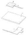
図1、図2及び図3を同時に参照し、それぞれが本発明の非侵襲型血糖センサーのモジュール概略図、構造概略図及び構造分解概略図である。
前記非侵襲型血糖センサーは、基板1と、第1金属層2と、第2金属層3と、導電塗布層21と、血糖測定ユニット4と、を備える。Referring to FIGS. 1, 2 and 3 at the same time, respectively, a module schematic diagram, a structure schematic diagram, and a structure exploded schematic diagram of the noninvasive blood glucose sensor of the present invention.
The noninvasive blood glucose sensor includes a
前記基板1は、分子基板及びセラミック基板からなる群から選択的に使用されることができる。前記第1金属層2は、前記基板1の一面に形成され、その中には少なくとも1つのマイクロストリップアンテナが埋設されている。
また、前記導電塗布層21は、第1金属層2の上に塗布されており、さらに血糖測定の感度及び精度を高めるために、この導電塗布層21の中に、ナノ金属粒子が選択的に混合されてもよい。
前記第2金属層3は、前記基板1の他面に形成され、図2に示すように、第2金属層3の上には、前記第1金属層2と重なっていない所定面積を有し、また、第2金属層3は、L字型に形成されており、第1金属層2は、L字型の凹陥部に設置されている。
上記のような設計は、広帯域効果を効果的に向上させることができる。同じように、第1金属層2と第2金属層3の形状は適度に変形することが可能であり、被覆された面積に部分的に重なっていない部分さえあれば、本発明の保護範囲内に含まれるものと認めるべきである。The
In addition, the
The
Such a design can effectively improve the broadband effect. Similarly, the shapes of the
血糖測定ユニット4は、第1金属層2及び前記第2金属層3とを同時に電気的に接続すると共に、無線周波信号が提供される。
前記無線周波信号は、1GHzから8GHzまでの周波数を有する。
また、使用者が前記非侵襲型血糖センサーを人体の任意の部位の外側に置く時に、前記血糖測定ユニット4から前記無線周波信号を第1金属層2までに提供し、血糖とは1GHzから8GHzまでの周波数範囲内に共振効果が生じることにより、血糖値を算出し、前記血糖測定ユニット4の上に表示させる。The blood
The radio frequency signal has a frequency from 1 GHz to 8 GHz.
Further, when the user places the non-invasive blood glucose sensor outside an arbitrary part of the human body, the radio frequency signal is provided from the blood
上記のように、本発明の構造については十分完全に開示される。最後に、発明の血糖(ぶどう糖)測定の正確度について説明する。
まず、図4に示す本発明の非侵襲型血糖センサーの第1測定データを示すグラフを参照し、この図は、3つの異なるグルコース濃度(GLucose 100mg/dL,GLucose 140mg/dL及びGLucose 160mg/dL)のぶどう糖溶液に対し、それぞれが異なる周波数において共振し、測定して得られた反射波損失(Return Loss)との関係を示すグラフである。
その測定条件としては、第2金属層3が基板1の上に第1金属層2を部分的に被覆しており、さらにその上には、導電塗布層21を有していないこと。図4に示すように、1GHzから8GHzまでの周波数において、その最大反射波損失のマージンが約−29dBで、波形の分離レベルが高く、容易に識別できる。As noted above, the structure of the present invention is fully disclosed. Finally, the accuracy of blood glucose (glucose) measurement according to the invention will be described.
First, referring to the graph showing the first measurement data of the non-invasive blood glucose sensor of the present invention shown in FIG. 4, this figure shows three different glucose concentrations (GLucose 100 mg / dL, GLucose 140 mg / dL and GLucose 160 mg / dL). Is a graph showing a relationship with the reflected wave loss (Return Loss) obtained by resonating at a different frequency and measured.
The measurement condition is that the
次に、図5に示す本発明の非侵襲型血糖センサーの第2測定データを示すグラフを参照し、この図は、同様に、3つの異なるグルコース濃度のぶどう糖溶液に対し、それぞれが異なる周波数において共振し、測定して得られた反射波損失との関係を示すグラフである。その測定条件としては、第2金属層3が基板1の上に第1金属層2を部分的に被覆しており、第1金属層2の上に導電塗布層21が増設される。
図5に示すように、1GHzから8GHzまでの周波数において、その最大反射波損失のマージンが約−31dBで、第1測定データを示すグラフと比較すると、この実施例が図面上にける波形の分離レベルがより高いため、より容易に識別できる。Next, referring to the graph showing the second measurement data of the non-invasive blood glucose sensor of the present invention shown in FIG. 5, this figure similarly shows three glucose solutions with different glucose concentrations at different frequencies. It is a graph which shows the relationship with the reflected wave loss obtained by resonating and measuring. As the measurement conditions, the
As shown in FIG. 5, when compared with the graph showing the first measurement data, the margin of the maximum reflected wave loss is about −31 dB at a frequency of 1 GHz to 8 GHz, and this example shows the waveform separation in the drawing. Because the level is higher, it is easier to identify.
最後に、図6に示す本発明の非侵襲型血糖センサーの第3測定データを示すグラフを参照し、この図は、同様に、3つの異なるグルコース濃度のぶどう糖溶液に対し、それぞれが異なる周波数において共振し、測定して得られた反射波損失との関係を示すグラフである。
その測定条件としては、第2金属層3が基板1の上に第1金属層2を部分的に被覆しており、第1金属層2の上の導電塗布層21の中に、ナノ金属粒子が混合されている。
図6に示すように、1GHzから8GHzまでの周波数において、その最大反射波損失のマージンが約−32dBで、第2測定データを示すグラフと比較すると、この実施例が図面上にける波形の分離レベルの差が大きいし、第1及び第2測定データを示すグラフと比較すると、波形の分離レベルも明らかにより優れたため、使用者がさらにより容易に識別することができる。Finally, referring to the graph showing the third measurement data of the non-invasive blood glucose sensor of the present invention shown in FIG. 6, this figure similarly shows three different glucose concentrations of glucose solutions at different frequencies. It is a graph which shows the relationship with the reflected wave loss obtained by resonating and measuring.
As the measurement conditions, the
As shown in FIG. 6, the margin of the maximum reflected wave loss at a frequency of 1 GHz to 8 GHz is about −32 dB. Compared with the graph showing the second measurement data, this example shows the waveform separation in the drawing. Compared with the graph showing the first and second measurement data, the level difference is large, and the waveform separation level is also clearly superior, so that the user can more easily identify.
上記のように、被覆レベルでのデータの比較を行うと、第1金属層2と第2金属層3が部分的に重なっている時に生じる反射波損失のマージンが十分に大きいことが明らかに分かる。
そのうち、反射波損失のピーク値の変化が大きければ、その測定の感度がより高い、また、波形上の分離レベルが高い場合において、使用者がより容易に識別することができる。同様に、面積が部分的に被覆される場合において、第1金属層2の上に導電塗布層21が設けられている時に測定して得られた反射波損失のピーク値の変化は、導電塗布層21が設けられていない時と比べ、より大きい。ここから分かるように、面積が部分的に被覆される場合において、導電塗布層21が設けられると、測定の感度がより好ましい。
また、波形の分離レベルを比較すると、導電塗布層21が設けられている設計も、導電塗布層21が設けられていない設計より明らかに優れている。最後に、第1金属層2と第2金属層3が同じように部分的に被覆され、かつ同じように導電塗布層21が設けられている場合に、導電塗布層21内に、ナノ金属粒子が混合されている時の反射波損失のピーク値は、ナノ金属粒子が混合されていない時と比べ、より大きい。As described above, when the data at the covering level is compared, it can be clearly seen that the margin of the reflected wave loss generated when the
Among them, if the change in the peak value of the reflected wave loss is large, the sensitivity of the measurement is higher, and the user can more easily identify when the separation level on the waveform is high. Similarly, when the area is partially covered, the change in the peak value of the reflected wave loss obtained when the
Further, when comparing the waveform separation levels, the design with the
以上から総括すると、第1金属層2と第2金属層3が同様に部分的に被覆され、また、同様に導電塗布層21が設けられており、かつナノ金属粒子が混合されている時に、その感度及び波形の分離レベルが最も好ましく、その次に導電塗布層21が単純に使用されている時の感度及び波形の分離レベルが好ましく、単に、面積が部分的に被覆される時の感度及び波形の分離レベルが最も劣っていることが分かる。
しかし、本実施例としては、被覆される面積の割合を変化させるだけで検出感度を著しく改善することが可能となる。Summing up from the above, when the
However, in this embodiment, the detection sensitivity can be remarkably improved only by changing the ratio of the covered area.
以上から分かるように、本発明の利点としては、人体外から血糖測定を行うことができる点がある。従来技術のように人体に侵襲的な測定方式を行う必要がなくなり、被覆される面積の割合を変化させることにより、測定の感度及び波形の識別度が改善され、さらに、金属層の上に導電塗布層を塗布することだけで、測定の感度及び波形の識別度がさらなる向上が可能になる。 As can be seen from the above, an advantage of the present invention is that blood glucose can be measured from outside the human body. It is no longer necessary to perform an invasive measurement method on the human body as in the prior art, and by changing the ratio of the area to be covered, the sensitivity of measurement and the identification of the waveform are improved, and further, the conductive layer is conductive on the metal layer. By simply applying the coating layer, the sensitivity of measurement and the degree of waveform discrimination can be further improved.
しかし、上記の詳細な説明は、単に、本発明の実施できる具体的な実施例を挙げて説明するにすぎない。
したがって、本発明はこれらの実施例に限定されるものではなく、本発明に掲示された技術思想を逸脱しない範囲内で、種々なる態様で実施しえること並びに変更もまた本発明の範囲に含まれることである。However, the foregoing detailed description is merely illustrative of specific examples in which the invention can be practiced.
Therefore, the present invention is not limited to these examples, and various modifications and changes can be made within the scope of the present invention without departing from the technical idea posted in the present invention. It is to be.
1 基板
2 第1金属層
21 導電塗布層
3 第2金属層
4 血糖測定ユニットDESCRIPTION OF
前記基板1は、高分子基板及びセラミック基板からなる群から選択的に使用されることができる。前記第1金属層2は、前記基板1の一面に形成され、その中には少なくとも1つのマイクロストリップアンテナが埋設されている。
また、前記導電塗布層21は、第1金属層2の上に塗布されており、さらに血糖測定の感度及び精度を高めるために、この導電塗布層21の中に、ナノ金属粒子が選択的に混合されてもよい。
前記第2金属層3は、前記基板1の他面に形成され、図2に示すように、第2金属層3の上には、前記第1金属層2と重なっていない所定面積を有し、また、第2金属層3は、L字型に形成されており、第1金属層2は、L字型の凹陥部に設置されている。
上記のような設計は、広帯域効果を効果的に向上させることができる。同じように、第1金属層2と第2金属層3の形状は適度に変形することが可能であり、被覆された面積に部分的に重なっていない部分さえあれば、本発明の保護範囲内に含まれるものと認めるべきである。
The
In addition, the
The
Such a design can effectively improve the broadband effect. Similarly, the shapes of the
Claims (8)
Translated fromJapaneseその中には少なくとも1つのマイクロストリップアンテナが埋設されており、前記基板の一面に形成された第1金属層と、
前記基板の他面に形成された第2金属層と、
前記第1金属層と前記第2金属層とを同時に電気的に接続すると共に、無線周波信号が提供される血糖測定ユニットと、を備える非侵襲型血糖センサーであって、
前記第2金属層は、広帯域効果を向上させるために、前記第1金属層と重なっていない所定面積を有し、また、使用者が前記非侵襲型血糖センサーを人体の任意の部位の外側に置く時に、前記血糖測定ユニットから前記無線周波信号を前記第1金属層まで提供して血糖との共振効果が生じることにより、血糖値を算出し、前記血糖測定ユニットの上に表示させることを特徴とする、
非侵襲型血糖センサー。A substrate,
At least one microstrip antenna is embedded therein, a first metal layer formed on one surface of the substrate,
A second metal layer formed on the other surface of the substrate;
A blood glucose measurement unit that electrically connects the first metal layer and the second metal layer at the same time and is provided with a radio frequency signal;
The second metal layer has a predetermined area that does not overlap the first metal layer in order to improve the broadband effect, and the user places the non-invasive blood glucose sensor outside an arbitrary part of the human body. When placing, a blood glucose level is calculated and displayed on the blood glucose measurement unit by providing the radio frequency signal from the blood glucose measurement unit to the first metal layer and causing a resonance effect with blood glucose. And
Non-invasive blood glucose sensor.
その中には少なくとも1つのマイクロストリップアンテナが埋設されており、前記基板の一面に形成された第1金属層と、
前記基板の他面に形成された第2金属層と、
前記第1金属層に塗布されている導電塗布層と、
前記第1金属層と前記第2金属層とを同時に電気的に接続すると共に、無線周波信号が提供される血糖測定ユニットと、を備える非侵襲型血糖センサーにおいて、
前記第2金属層は、広帯域効果を向上させるために、前記第1金属層と重なっていない所定面積を有し、前記導電塗布層の塗布面積は、第2金属層の面積より大きいまたは小さい面積であり、また、使用者が前記非侵襲型血糖センサーを人体の任意の部位の外側に置く時に、前記血糖測定ユニットから前記無線周波信号を前記第1金属層までに提供して血糖との共振効果が生じることにより、血糖値を算出し、前記血糖測定ユニットの上に表示させることを特徴とする、非侵襲型血糖センサー。A substrate,
At least one microstrip antenna is embedded therein, a first metal layer formed on one surface of the substrate,
A second metal layer formed on the other surface of the substrate;
A conductive coating layer applied to the first metal layer;
In a non-invasive blood glucose sensor comprising: a blood glucose measurement unit that electrically connects the first metal layer and the second metal layer simultaneously and is provided with a radio frequency signal;
The second metal layer has a predetermined area that does not overlap the first metal layer in order to improve the broadband effect, and the coating area of the conductive coating layer is larger or smaller than the area of the second metal layer In addition, when the user places the non-invasive blood glucose sensor outside an arbitrary part of the human body, the radio frequency signal is provided from the blood glucose measurement unit to the first metal layer to resonate with blood glucose. A blood glucose level is calculated when an effect is produced and displayed on the blood glucose measurement unit.
Priority Applications (1)
| Application Number | Priority Date | Filing Date | Title |
|---|---|---|---|
| JP2013019523AJP5600759B2 (en) | 2013-02-04 | 2013-02-04 | Non-invasive blood glucose sensor |
Applications Claiming Priority (1)
| Application Number | Priority Date | Filing Date | Title |
|---|---|---|---|
| JP2013019523AJP5600759B2 (en) | 2013-02-04 | 2013-02-04 | Non-invasive blood glucose sensor |
Publications (2)
| Publication Number | Publication Date |
|---|---|
| JP2014147637Atrue JP2014147637A (en) | 2014-08-21 |
| JP5600759B2 JP5600759B2 (en) | 2014-10-01 |
Family
ID=51571185
Family Applications (1)
| Application Number | Title | Priority Date | Filing Date |
|---|---|---|---|
| JP2013019523AExpired - Fee RelatedJP5600759B2 (en) | 2013-02-04 | 2013-02-04 | Non-invasive blood glucose sensor |
Country Status (1)
| Country | Link |
|---|---|
| JP (1) | JP5600759B2 (en) |
Cited By (15)
| Publication number | Priority date | Publication date | Assignee | Title |
|---|---|---|---|---|
| US11058331B1 (en) | 2020-02-06 | 2021-07-13 | Know Labs, Inc. | Analyte sensor and system with multiple detector elements that can transmit or receive |
| WO2021156747A1 (en)* | 2020-02-06 | 2021-08-12 | Know Labs, Inc. | Detection of an analyte using different combinations of detector elements that can transmit or receive |
| WO2021156734A1 (en)* | 2020-02-06 | 2021-08-12 | Know Labs, Inc. | Analyte sensor and system with multiple detector elements that can transmit or receive |
| US11147521B2 (en) | 2018-09-11 | 2021-10-19 | Samsung Electronics Co., Ltd. | Apparatus and method for health care |
| US11193923B2 (en) | 2020-02-06 | 2021-12-07 | Know Labs, Inc. | Detection of an analyte using multiple elements that can transmit or receive |
| US11419507B2 (en) | 2018-09-11 | 2022-08-23 | Samsung Electronics Co., Ltd. | Bio-information estimating apparatus and bio-information estimating method |
| US11517223B2 (en) | 2018-12-13 | 2022-12-06 | Samsung Electronics Co., Ltd. | Apparatus and method for estimating blood glucose |
| US11802843B1 (en) | 2022-07-15 | 2023-10-31 | Know Labs, Inc. | Systems and methods for analyte sensing with reduced signal inaccuracy |
| US11903701B1 (en) | 2023-03-22 | 2024-02-20 | Know Labs, Inc. | Enhanced SPO2 measuring device |
| US12007338B2 (en) | 2020-09-09 | 2024-06-11 | Know Labs Inc. | In vitro sensor for analyzing in vitro flowing fluids |
| US12019034B2 (en) | 2020-09-09 | 2024-06-25 | Know Labs, Inc. | In vitro sensing methods for analyzing in vitro flowing fluids |
| US12033451B2 (en) | 2022-08-15 | 2024-07-09 | Know Labs, Inc. | Systems and methods for analyte-based access controls |
| US12170145B2 (en) | 2023-03-22 | 2024-12-17 | Know Labs, Inc. | System and method for software and hardware activation based on real-time health parameters |
| US12193810B2 (en) | 2023-03-21 | 2025-01-14 | Know Labs, Inc. | System and method for performing surgery with real-time health parameter monitoring |
| US12318203B2 (en) | 2022-08-15 | 2025-06-03 | Know Labs, Inc. | Vehicle interface systems and methods for analyte-based access control |
Citations (2)
| Publication number | Priority date | Publication date | Assignee | Title |
|---|---|---|---|---|
| JP2004526492A (en)* | 2001-03-06 | 2004-09-02 | ペンドラゴン・メディカル・リミテッド | Method and apparatus for determining the concentration of a substance in a body fluid |
| JP2008191139A (en)* | 2007-01-09 | 2008-08-21 | Mitsubishi Electric Corp | Physical quantity measuring device |
- 2013
- 2013-02-04JPJP2013019523Apatent/JP5600759B2/ennot_activeExpired - Fee Related
Patent Citations (2)
| Publication number | Priority date | Publication date | Assignee | Title |
|---|---|---|---|---|
| JP2004526492A (en)* | 2001-03-06 | 2004-09-02 | ペンドラゴン・メディカル・リミテッド | Method and apparatus for determining the concentration of a substance in a body fluid |
| JP2008191139A (en)* | 2007-01-09 | 2008-08-21 | Mitsubishi Electric Corp | Physical quantity measuring device |
Cited By (16)
| Publication number | Priority date | Publication date | Assignee | Title |
|---|---|---|---|---|
| US11147521B2 (en) | 2018-09-11 | 2021-10-19 | Samsung Electronics Co., Ltd. | Apparatus and method for health care |
| US11419507B2 (en) | 2018-09-11 | 2022-08-23 | Samsung Electronics Co., Ltd. | Bio-information estimating apparatus and bio-information estimating method |
| US11517223B2 (en) | 2018-12-13 | 2022-12-06 | Samsung Electronics Co., Ltd. | Apparatus and method for estimating blood glucose |
| WO2021156747A1 (en)* | 2020-02-06 | 2021-08-12 | Know Labs, Inc. | Detection of an analyte using different combinations of detector elements that can transmit or receive |
| WO2021156734A1 (en)* | 2020-02-06 | 2021-08-12 | Know Labs, Inc. | Analyte sensor and system with multiple detector elements that can transmit or receive |
| US11193923B2 (en) | 2020-02-06 | 2021-12-07 | Know Labs, Inc. | Detection of an analyte using multiple elements that can transmit or receive |
| US11330997B2 (en) | 2020-02-06 | 2022-05-17 | Know Labs, Inc. | Detection of an analyte using different combinations of detector elements that can transmit or receive |
| US11058331B1 (en) | 2020-02-06 | 2021-07-13 | Know Labs, Inc. | Analyte sensor and system with multiple detector elements that can transmit or receive |
| US12007338B2 (en) | 2020-09-09 | 2024-06-11 | Know Labs Inc. | In vitro sensor for analyzing in vitro flowing fluids |
| US12019034B2 (en) | 2020-09-09 | 2024-06-25 | Know Labs, Inc. | In vitro sensing methods for analyzing in vitro flowing fluids |
| US11802843B1 (en) | 2022-07-15 | 2023-10-31 | Know Labs, Inc. | Systems and methods for analyte sensing with reduced signal inaccuracy |
| US12033451B2 (en) | 2022-08-15 | 2024-07-09 | Know Labs, Inc. | Systems and methods for analyte-based access controls |
| US12318203B2 (en) | 2022-08-15 | 2025-06-03 | Know Labs, Inc. | Vehicle interface systems and methods for analyte-based access control |
| US12193810B2 (en) | 2023-03-21 | 2025-01-14 | Know Labs, Inc. | System and method for performing surgery with real-time health parameter monitoring |
| US11903701B1 (en) | 2023-03-22 | 2024-02-20 | Know Labs, Inc. | Enhanced SPO2 measuring device |
| US12170145B2 (en) | 2023-03-22 | 2024-12-17 | Know Labs, Inc. | System and method for software and hardware activation based on real-time health parameters |
Also Published As
| Publication number | Publication date |
|---|---|
| JP5600759B2 (en) | 2014-10-01 |
Similar Documents
| Publication | Publication Date | Title |
|---|---|---|
| JP5600759B2 (en) | Non-invasive blood glucose sensor | |
| US20140213870A1 (en) | Non-Invasive Blood glucose Sensor | |
| Yilmaz et al. | Detecting vital signs with wearable wireless sensors | |
| US20220386889A1 (en) | Non-intrusive oxygen sensing device | |
| US10702153B2 (en) | Wound dressing with reusable electronics for wireless monitoring | |
| Hanna et al. | Wearable flexible body matched electromagnetic sensors for personalized non-invasive glucose monitoring | |
| Park et al. | Noncontact RF vital sign sensor for continuous monitoring of driver status | |
| JP2017538474A (en) | Server apparatus and wearable device for blood glucose monitoring, and related method | |
| US20120150000A1 (en) | Non-Invasive Monitoring Device | |
| Zhao et al. | Technology platforms for remote monitoring of vital signs in the new era of telemedicine | |
| Ahmed et al. | Noncontact assessment for fatigue based on heart rate variability using IR-UWB radar | |
| Chen et al. | Arteriovenous fistula flow dysfunction surveillance: early detection using pulse radar sensor and machine learning classification | |
| Yunos et al. | Non-invasive glucose monitoring devices: A review | |
| Wu et al. | Highly sensitive blood glucose monitoring sensor with adjustable resonant frequency based on MP-CSRR | |
| Wang et al. | Noninvasive, intelligent blood glucose monitoring on fingertip using dual-band fusion and LSTM-R network | |
| Kiani et al. | Investigation of microwave resonant sensors for use in detecting changes of noninvasive blood glucose concentration | |
| CN110402104A (en) | Blood pressure measuring device, method and program | |
| Wang et al. | Non-invasive, intelligent, and continuous monitoring of human blood glucose with UWB dual-antenna and cascade CNN | |
| Sethi et al. | Thumb positioning analysis of new elliptical‐shaped microwave sensors for non‐invasive glucose monitoring | |
| CN106667498A (en) | Physiological detection device | |
| Bamatraf | Noninvasive continuous glucose monitoring on aqueous solutions using microwave sensor with machine learning | |
| CN107997769A (en) | A kind of microwave time delay Woundless blood sugar Concentration Testing method based on Ear lobe blood liquid layer | |
| CN110916680A (en) | Non-invasive blood glucose concentration detection method based on S21 phase | |
| KR20250000762A (en) | Machine learning-assisted wearable pressure-sensing device for decoding human pulse signals and HRV information with different mental health conditions | |
| CN110074790A (en) | Microwave time-domain signal Woundless blood sugar concentration detection method based on Ear lobe blood liquid layer |
Legal Events
| Date | Code | Title | Description |
|---|---|---|---|
| A521 | Written amendment | Free format text:JAPANESE INTERMEDIATE CODE: A523 Effective date:20140604 | |
| TRDD | Decision of grant or rejection written | ||
| A01 | Written decision to grant a patent or to grant a registration (utility model) | Free format text:JAPANESE INTERMEDIATE CODE: A01 Effective date:20140722 | |
| A61 | First payment of annual fees (during grant procedure) | Free format text:JAPANESE INTERMEDIATE CODE: A61 Effective date:20140818 | |
| R150 | Certificate of patent or registration of utility model | Ref document number:5600759 Country of ref document:JP Free format text:JAPANESE INTERMEDIATE CODE: R150 | |
| LAPS | Cancellation because of no payment of annual fees |