JP2014146152A - Information processing device and control method of information processing device - Google Patents
Information processing device and control method of information processing deviceDownload PDFInfo
- Publication number
- JP2014146152A JP2014146152AJP2013014048AJP2013014048AJP2014146152AJP 2014146152 AJP2014146152 AJP 2014146152AJP 2013014048 AJP2013014048 AJP 2013014048AJP 2013014048 AJP2013014048 AJP 2013014048AJP 2014146152 AJP2014146152 AJP 2014146152A
- Authority
- JP
- Japan
- Prior art keywords
- power
- wallpaper
- main body
- information processing
- display device
- Prior art date
- Legal status (The legal status is an assumption and is not a legal conclusion. Google has not performed a legal analysis and makes no representation as to the accuracy of the status listed.)
- Pending
Links
Images


Classifications
- G—PHYSICS
- G09—EDUCATION; CRYPTOGRAPHY; DISPLAY; ADVERTISING; SEALS
- G09G—ARRANGEMENTS OR CIRCUITS FOR CONTROL OF INDICATING DEVICES USING STATIC MEANS TO PRESENT VARIABLE INFORMATION
- G09G5/00—Control arrangements or circuits for visual indicators common to cathode-ray tube indicators and other visual indicators
- G09G5/10—Intensity circuits
- G—PHYSICS
- G06—COMPUTING OR CALCULATING; COUNTING
- G06F—ELECTRIC DIGITAL DATA PROCESSING
- G06F1/00—Details not covered by groups G06F3/00 - G06F13/00 and G06F21/00
- G06F1/26—Power supply means, e.g. regulation thereof
- G06F1/32—Means for saving power
- G06F1/3203—Power management, i.e. event-based initiation of a power-saving mode
- G06F1/3206—Monitoring of events, devices or parameters that trigger a change in power modality
- G06F1/3215—Monitoring of peripheral devices
- G06F1/3218—Monitoring of peripheral devices of display devices
- G—PHYSICS
- G06—COMPUTING OR CALCULATING; COUNTING
- G06F—ELECTRIC DIGITAL DATA PROCESSING
- G06F1/00—Details not covered by groups G06F3/00 - G06F13/00 and G06F21/00
- G06F1/26—Power supply means, e.g. regulation thereof
- G06F1/32—Means for saving power
- G06F1/3203—Power management, i.e. event-based initiation of a power-saving mode
- G06F1/3234—Power saving characterised by the action undertaken
- G06F1/325—Power saving in peripheral device
- G06F1/3265—Power saving in display device
- G—PHYSICS
- G09—EDUCATION; CRYPTOGRAPHY; DISPLAY; ADVERTISING; SEALS
- G09G—ARRANGEMENTS OR CIRCUITS FOR CONTROL OF INDICATING DEVICES USING STATIC MEANS TO PRESENT VARIABLE INFORMATION
- G09G2330/00—Aspects of power supply; Aspects of display protection and defect management
- G09G2330/02—Details of power systems and of start or stop of display operation
- G09G2330/021—Power management, e.g. power saving
- Y—GENERAL TAGGING OF NEW TECHNOLOGICAL DEVELOPMENTS; GENERAL TAGGING OF CROSS-SECTIONAL TECHNOLOGIES SPANNING OVER SEVERAL SECTIONS OF THE IPC; TECHNICAL SUBJECTS COVERED BY FORMER USPC CROSS-REFERENCE ART COLLECTIONS [XRACs] AND DIGESTS
- Y02—TECHNOLOGIES OR APPLICATIONS FOR MITIGATION OR ADAPTATION AGAINST CLIMATE CHANGE
- Y02D—CLIMATE CHANGE MITIGATION TECHNOLOGIES IN INFORMATION AND COMMUNICATION TECHNOLOGIES [ICT], I.E. INFORMATION AND COMMUNICATION TECHNOLOGIES AIMING AT THE REDUCTION OF THEIR OWN ENERGY USE
- Y02D10/00—Energy efficient computing, e.g. low power processors, power management or thermal management
Landscapes
- Engineering & Computer Science (AREA)
- Theoretical Computer Science (AREA)
- Physics & Mathematics (AREA)
- General Physics & Mathematics (AREA)
- General Engineering & Computer Science (AREA)
- Computer Hardware Design (AREA)
- Power Sources (AREA)
- Controls And Circuits For Display Device (AREA)
Abstract
Translated fromJapaneseDescription
Translated fromJapanese本発明の実施形態は、情報処理装置および情報処理装置の制御方法に関する。 Embodiments described herein relate generally to an information processing apparatus and a method for controlling the information processing apparatus.
液晶表示装置などを備えた電子機器においては、表示画面の表示のベースとして所謂壁紙を多様に選択できる構成が採られている。他方でユーザー等からの省電力への要望がある。しかしながら、壁紙の種類毎の省電力情報をユーザーへ的確に知らせて、壁紙切り替えによる省電力機能を容易に実現するための手段は知られていない。 In an electronic device including a liquid crystal display device or the like, a configuration is employed in which so-called wallpaper can be selected in various ways as a display screen display base. On the other hand, there is a demand for power saving from users. However, there is no known means for accurately notifying the user of the power saving information for each type of wallpaper and easily realizing the power saving function by wallpaper switching.
本発明の実施の形態は、壁紙切り替えによる省電力機能を容易に実現する技術を提供することを目的とする。 An object of the embodiment of the present invention is to provide a technique for easily realizing a power saving function by wallpaper switching.
上記課題を解決するために、実施形態によれば情報処理装置は、本体と、表示装置と、この表示装置に複数の壁紙の内の一つを表示させる、前記本体に内在するGPUと、前記本体及び前記表示装置に供給される電力の電力量を計測する計測手段と、前記複数の壁紙それぞれに対応するこの電力量を登録する登録手段とを備える。 In order to solve the above-described problem, according to the embodiment, an information processing apparatus includes a main body, a display device, a GPU included in the main body that causes the display device to display one of a plurality of wallpapers, and the display device. Measuring means for measuring the amount of power supplied to the main body and the display device, and registration means for registering the amount of power corresponding to each of the plurality of wallpapers.
以下、一実施形態を図1乃至図8を参照して説明する。 Hereinafter, an embodiment will be described with reference to FIGS. 1 to 8.
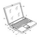
まず、図1を参照して、情報処理装置の実施形態にかかる電子機器の構成について説明する。この電子機器は、例えば、バッテリによって駆動可能なノートブック型の携帯型パーソナルコンピュータ10として実現されている。図1は、ディスプレイユニットを開いた状態におけるパーソナルコンピュータ10を正面側から見た斜視図である。 First, the configuration of an electronic apparatus according to an embodiment of the information processing apparatus will be described with reference to FIG. The electronic apparatus is realized as a notebook portable
パーソナルコンピュータ10は、コンピュータ本体11と、ディスプレイユニット12とから構成される。ディスプレイユニット12には、LCD19(Liquid Crystal Display)から構成される表示装置が組み込まれている。 The
ディスプレイユニット12は、コンピュータ本体11に支持され、そのコンピュータ本体11に対してコンピュータ本体11の上面が露出される開放位置とコンピュータ本体11の上面がディスプレイユニット12によって覆れる閉塞位置との間を回動自由に取り付けられている。コンピュータ本体11は薄い箱形の筐体を有しており、その上面にはキーボード13、パーソナルコンピュータ10を電源オン/オフするための電源スイッチ14およびタッチパッド15が配置されている。 The
また、コンピュータ本体11には、電源コネクタ20が設けられている。電源コネクタ20はコンピュータ本体11の側面、例えば左側面に設けられている。この電源コネクタ20には、外部電源装置が取り外し自在に接続される。外部電源装置としては、ACアダプターを用いることが出来る。ACアダプターは商用電源(AC電力)をDC電力に変換する電源装置である。 The computer
電源コネクタ20は、ACアダプターのような外部電源装置から導出される電源プラグが取り外し自在に接続可能なジャックから構成されている。バッテリ17は、例えば、コンピュータ本体11の後端部に取り外し自在に装着される。 The
パーソナルコンピュータ10は、外部電源装置からの電力、バッテリ17からの電力によって駆動される。パーソナルコンピュータ10の電源コネクタ20に外部電源装置が接続されているならば、パーソナルコンピュータ10は外部電源装置からの電力によって駆動される。また、外部電源装置からの電力は、バッテリ17を充電するためにも用いられる。バッテリ17の充電は、パーソナルコンピュータ10が電源オンされている期間中のみならず、パーソナルコンピュータ10が電源オフされている期間中にも実行してもよい。パーソナルコンピュータ10の電源コネクタ20に外部電源装置が接続されていない期間中は、パーソナルコンピュータ10はバッテリ17からの電力によって駆動される。 The
また、コンピュータ本体11には、外部電源装置の有無等の各種電源ステータスを通知するためのインジケータ16が設けられている。このインジケータ16は、例えば、コンピュータ本体11の正面に設けられている。インジケータ16は、LEDから構成し得る。なお、スペーサ18はコンピュータ本体11の後部を高く保持するためのものである。 The computer
図2は、パーソナルコンピュータ10のシステム構成を示している。パーソナルコンピュータ10は、CPU111、主メモリ113、グラフィクスコントローラ114、システムコントローラ115、ハードディスクドライブ(HDD)116、光ディスクドライブ(ODD)117、BIOS−ROM118、エンベデッドコントローラ/キーボードコントローラ(EC/KBC)119、電源コントローラ(PSC)120、電源回路121、ACアダプター122等を備えている。ACアダプター122は上述の外部電源装置として使用される。本実施形態において、電源コントローラ(PSC)120と電源回路121とは、外部電源装置(ACアダプター)からの電力量を測定するための消費電力測定回路123として機能する。消費電力測定回路123は、パーソナルコンピュータ10が電源オンされている期間だけでなく、電源オフされている期間においても電力量を測定する。本実施形態では、例えば外部電源装置(ACアダプター)から供給される電力をパーソナルコンピュータ10における消費電力として扱う。電力量を計測する計測手段の主体であるEC/KBC119は、消費電力測定回路123によって測定された電力量(電流値、電圧値)、すなわち消費電力値を示すデータを読み取り、システムコントローラ115を通じてCPU111(オペレーティングシステム(OS))に出力する。 FIG. 2 shows the system configuration of the
CPU111は、パーソナルコンピュータ10の各コンポーネントの動作を制御するプロセッサである。このCPU111は、HDD116から主メモリ113にロードされる各種ソフトウェア、例えば、オペレーティングシステム(OS)113aおよび各種ユーティリティプログラムやアプリケーションプログラムを実行する。 The
ユーティリティプログラムには、ピークシフト機能を実現するためのピークシフトユーティリティ113bが含まれる。ピークシフト機能は、社会全体における電力消費のピーク時間帯(昼間、特に夏期の日中13時〜16時など)に、外部電源装置(ACアダプター)からの電力供給を停止してバッテリ駆動に切り替え、電力消費の少ない時間帯(夜間)にバッテリの充電をするように電源管理する機能である。 The utility program includes a
アプリケーションプログラムには、消費電力測定回路123によって測定された消費電力値を示すデータを処理する消費電力量測定プログラム113cが含まれる。消費電力量測定プログラム113cは、EC/KBC119のメモリ119a(揮発性のメモリ)に記録された消費電力値を示すデータを、OS113aを通じて読み出してHDD116に記録する。また、消費電力量測定プログラム113cは、HDD116に記録された消費電力値を示すデータを外部装置に送信する送信処理、外部装置に送信するデータを生成するデータ生成処理、消費電力値を示すデータをもとにした電力量の変化を表す画面(グラフ等)を表示する表示処理等を実行する。データ生成処理には、要求されるデータ精度(データ量)とするためのデータ補完処理が含まれる。 The application program includes a power
また、CPU111は、不揮発性メモリであるBIOS−ROM118に格納されたBIOS(基本入出力システム:Basic Input Output System)も実行する。BIOS(以下BIOS)はハードウェア制御のためのシステムプログラムである。 The
グラフィクスコントローラ114は、パーソナルコンピュータ10のディスプレイモニタとして使用されるLCD19を制御する表示コントローラである。
システムコントローラ115は、PCIバス1に接続されており、PCIバス1上の各デバイスとの通信を実行する。PCIバス1には、例えば通信デバイス124が接続される。通信デバイス124は、CPU111の制御のもとで、ネットワークを介した外部装置(例えば、データサーバ)との通信を制御する。また、システムコントローラ115は、ハードディスクドライブ(HDD)116および光ディスクドライブ(ODD)117を制御するためのSerial ATAコントローラを内蔵している。The
The
EC/KBC119、電源コントローラ(PSC)120、およびバッテリ17は、I2Cバスのようなシリアルバス2を介して相互接続され、システムコントローラ115とLPCバスを介して接続されている。EC/KBC119は、パーソナルコンピュータ10の電力管理を実行するための電源管理コントローラであり、例えば、キーボード(KB)13およびタッチパッド15などを制御するキーボードコントローラを内蔵した1チップマイクロコンピュータとして実現されている。EC/KBC119は、ユーザーによる電源スイッチ14の操作に応じてパーソナルコンピュータ10を電源オンおよび電源オフする機能を有している。パーソナルコンピュータ10の電源オンおよび電源オフの制御は、EC/KBC119とPSC120との協働動作によって実行される。EC/KBC119から送信されるオン信号を受けると、PSC120は電源回路121を制御してパーソナルコンピュータ10の各内部電源をオンする。また、EC/KBC119から送信されるオフ信号を受けると、PSC120は電源回路121を制御してパーソナルコンピュータ10の各内部電源をオフする。EC/KBC119、PSC120、および電源回路121は、パーソナルコンピュータ10が電源オフされている期間中も、バッテリ17、またはACアダプター122からの電力によって動作する。The EC /
電源回路121は、コンピュータ本体11に装着されたバッテリ17からの電力、またはコンピュータ本体11に外部電源として接続されるACアダプター122からの電力を用いて、各コンポーネントへ供給すべき電力(動作電源)を生成する。コンピュータ本体11にACアダプター122が接続されている場合には、電源回路121は、ACアダプター122からの電力を用いて各コンポーネントへの動作電源を生成すると共に、充電回路(図示せず)をオンすることによってバッテリ17を充電する。電源回路121には、ACアダプター122の電圧値及び電流値、バッテリ17の電圧値及び電流値を示す信号を出力する検出回路121aが含まれる。PSC120は、検出回路121aから出力される信号をもとに、AC電源の電流値/電圧値を示すデータ、バッテリ17の電流値/電圧値を示すデータを生成する。 The
本実施形態におけるEC/KBC119、PSC120、および電源回路121は、パーソナルコンピュータ10が電源オンされている期間だけでなく、電源オフされている期間中も消費電力測定回路123により測定される消費電力値を示すデータを測定し、このデータを記録するための動作をする。 In the present embodiment, the EC /
EC/KBC119(以下EC)は、電源オンされている期間では、PSC120から入力される消費電力値を示すデータを直ぐにシステムコントローラ115を通じてCPU111(OS113a、消費電力量測定プログラム113c)に出力し、消費電力量測定プログラム113cがそのデータをHDD116に記録する。一方、電源オフされている期間では、PSC120から入力される消費電力値を示すデータを内部のメモリ119aに一時記録して、次の電源オン時にシステムコントローラ115を通じてCPU111(OS113a、消費電力量測定プログラム113c)に出力し、消費電力量測定プログラム113cがそのデータをHDD116に記録する。 The EC / KBC 119 (hereinafter referred to as EC) immediately outputs data indicating the power consumption value input from the
さて本実施形態の機能はLCDのような表示装置を有し、特に表示画像によるLEDバックライト電力低減機能を有するグラフィックスを搭載した機器に適用する (図3参照) 。即ち図3は、上記のような構成内における中心となる構成について示している。 The function of the present embodiment has a display device such as an LCD, and is applied particularly to a device equipped with graphics having a function of reducing LED backlight power by a display image (see FIG. 3). That is, FIG. 3 shows a central configuration in the above configuration.
ここで図3(a)は代表的なHW構成を示していて、各部は図2の同一番号の部分に対応している。なお図2の例では、チップセットが単一のシステムコントローラ115として実現されている。 Here, FIG. 3A shows a typical HW configuration, and each part corresponds to a part having the same number in FIG. In the example of FIG. 2, the chip set is realized as a
また図3(b)では、図3(a)のGPU(Graphics Processing Unit)の機能がCPU111aに内蔵されている。更に図3(c)では、図3(a)のCPU111aとチップセット115とが、CPU111bとして1チップモデルとして構成されている。 In FIG. 3B, the function of a GPU (Graphics Processing Unit) in FIG. 3A is built in the
次に、壁紙切り替えによる省電力機能の実装例を以下に説明する。まず、壁紙切り替えによる省電力機能(アプリケーション)を起動した場合のCPU111を主体とする手順を図4以下に示す。 Next, an implementation example of the power saving function by wallpaper switching will be described below. First, FIG. 4 and the following shows a procedure mainly performed by the
図4は、一実施形態の壁紙切り替えによる省電力機能の全体処理手順を示す図である。
ステップS41: 壁紙の選択と登録をする。即ちユーザーに使用したい壁紙を登録してもらう。既に使用可能な現在の壁紙は、例えばデフォルトで登録済みであり、同様な使用可能状態で追加登録すればよい。例えばユーザーはインターネットから好みの壁紙をダウンロードして、この壁紙はCPU111によりHDD116に取り込まれる。FIG. 4 is a diagram illustrating an overall processing procedure of the power saving function by wallpaper switching according to an embodiment.
Step S41: Select and register wallpaper. That is, ask the user to register the wallpaper you want to use. The current wallpaper that can be used is registered by default, for example, and may be additionally registered in a similar usable state. For example, the user downloads a favorite wallpaper from the Internet, and this wallpaper is taken into the
ステップS42: 壁紙ごとの電力測定をする。方法としては、登録した壁紙を切り替えて、デスクトップアイドル状態での電力システム電力(下記注1)またはLEDバックライト電力(下記注2)を測定する。なお、機器がACアダプター駆動時とバッテリ駆動時でグラフィックス省電力機能設定が異なる可能性があるため、電力測定はACアダプター駆動時とバッテリ駆動時でそれぞれ測定する。詳しいフローは図5以下に関して説明する。Step S42: The power is measured for each wallpaper. The method is to switch the registered wallpaper and measure the power system power (Note 1 below) or LED backlight power (Note 2 below) in the desktop idle state. Note that graphics power-saving function settings may differ when the device is driven by an AC adapter and when it is driven by a battery, so power measurements are measured when the AC adapter is driven and when it is driven by a battery. The detailed flow will be described with reference to FIG.
ステップS43: 省電力用壁紙の選択をする。壁紙ごとの省電力度合いを示して(図7参照)ユーザーに省電力用壁紙を選択してもらう。デフォルトでは最も電力が低かった壁紙を省電力用壁紙として選択しておく。詳しくは図7に関して説明する。Step S43: A power saving wallpaper is selected. The power saving level for each wallpaper is shown (see FIG. 7), and the user selects the power saving wallpaper. By default, the wallpaper with the lowest power is selected as the power saving wallpaper. Details will be described with reference to FIG.
ステップS44: 壁紙切り替え設定をする。ユーザーに壁紙の切り替えタイミングや条件を設定してもらう。
例えばユーザーはタッチパネル15に付随する右ボタンをクリックして、CPU111に設定メニューをGPU経由で表示装置(LCD)に表示させる。更に下記(1)〜(3)に対応するサブメニューをクリックして開いた後、(1)〜(3)に対応する各ラジオボタンで選ぶように構成しておく。Step S44: Set wallpaper switching. Have the user set wallpaper switching timings and conditions.
For example, the user clicks the right button attached to the
切り替え設定例は次のようである。(1)〜(3)はそれぞれに選択可能である。
(1)常に省電力用壁紙を使用
(2)バッテリ駆動時に省電力用壁紙に切り替える
(3)ユーザー操作がない場合に省電力用壁紙に切り替える
(注1:システム電力の場合)
現行システムではACアダプター・バッテリ駆動時ともシステム電力を測定するための回路が一般的に備わっており、新規回路追加がいらない。ただしアイドル時の電力の算出は次のようになる。An example of the switching setting is as follows. Each of (1) to (3) can be selected.
(1) Always use power-saving wallpaper (2) Switch to power-saving wallpaper when running on battery (3) Switch to power-saving wallpaper when there is no user operation (Note 1: System power)
Current systems generally have a circuit for measuring system power even when powered by an AC adapter or battery, and no new circuit is required. However, the calculation of power during idling is as follows.
(A)ACアダプター駆動時はDC-IN電圧・電流値をEC(図3(a))で測定しシステム電力を算出する
(B)バッテリ駆動時はバッテリ電圧・電流値をEC(図3(a))で測定しバッテリ電力を算出する
(注2:LEDバックライト電力を直接測定する場合)
LEDバックライト電源ラインに電流検出抵抗を追加し、LEDバックライト電源の電圧・電流値をマイコン(EC)で測定する回路が必要となる。システム電力と比べLEDバックライト電力データが正確に測定でき、測定時間も短くてすむ。即ち、ACアダプター・バッテリ駆動時とも、LEDバックライト電圧・電流値をマイコン(EC)で測定し電力を算出する。(A) When AC adapter is driven, DC-IN voltage / current value is measured with EC (Fig. 3 (a)) and system power is calculated. (B) When battery is driven, battery voltage / current value is EC (Fig. 3 ( a)) to measure and calculate battery power (Note 2: Direct measurement of LED backlight power)
A circuit to measure the voltage and current values of the LED backlight power supply with a microcomputer (EC) is required, by adding a current detection resistor to the LED backlight power supply line. Compared with system power, LED backlight power data can be measured accurately and measurement time is shorter. That is, even when the AC adapter and battery are driven, the LED backlight voltage / current value is measured by the microcomputer (EC) to calculate the power.
図5は、実施形態の壁紙ごとの電力測定処理フロー図である。上記ステップS42を詳細化したサブルーチンである。
ステップS51: 本機能以外の起動中の全てのアプリケーションの終了要求をCPU111はユーザーに向け表示する。
ステップS52: これら全アプリケーションの終了をユーザーはタッチパネル15に付随するボタンをクリックして実施する。
ステップS53: これらアプリケーションが終了したかCPU111は判定する。この判定がYesの場合はステップS55に飛び、Noの場合は次のステップS54を実施後にステップS55に進む。FIG. 5 is a flowchart of a power measurement process for each wallpaper according to the embodiment. This is a subroutine that details step S42.
Step S51: The
Step S52: The user clicks a button associated with the
Step S53: The
ステップS54: 正確な電力測定ができない可能性がある旨をCPU111はユーザーに向け警告表示する。
ステップS55: ACアダプターを接続する旨の要求をCPU111はユーザーに向け表示する。
ステップS56: ACアダプターを接続しているかCPU111は判定する。この判定がYesの場合は次のステップS58に進み、Noの場合はステップS57を実施後にステップS62に飛ぶ。Step S54: The
Step S55: The
Step S56: The
ステップS57: ACアダプター接続時の電力測定をしない旨をCPU111はユーザーに向け警告表示する。
ステップS58: 電力測定中は機器に触れないようCPU111はユーザーに向け警告表示する(アイドル状態の電力を測定するため)。
ステップS59: ACアダプター駆動時の電力測定をCPU111は開始する。
ステップS60: 壁紙切り替え電力測定処理をCPU111はする。詳しくは図6に関して説明する。
ステップS61: CPU111は電源回路121を用いてバッテリ駆動に切り替える。
ステップS62: 電力測定中は機器に触れないようCPU111はユーザーに向け警告表示する。
ステップS63: 消費電力測定回路123はバッテリ駆動時の電力測定を開始する。
ステップS64: ステップS60と同様にCPU111は壁紙切り替え電力測定処理をする。
ステップS65: ACアダプターを接続しているかCPU111はPSC120、EC/KBC119経由で判定する。この判定がYesの場合は次のステップS58に進み、Noの場合は処理を終了する。Step S57: The
Step S58: During the power measurement, the
Step S59: The
Step S60: The
Step S61: The
Step S62: During power measurement, the
Step S63: The power
Step S64: As with step S60, the
Step S65: Whether the AC adapter is connected is determined by the
ステップS66: CPU111はACアダプター駆動に切り替え、処理を終了する。
図6は、実施形態の壁紙ごとの電力測定処理フロー図である。上記ステップS60、ステップS64を詳細化したサブルーチンである。
ステップS71: CPU111は輝度を最大(100%)に設定する。
ステップS72: CPU111は壁紙切り替えを行う。
ステップS73: 消費電力測定回路123はデスクトップアイドル状態でのシステム電力またはLEDバックライト電力の測定を行う。
ステップS74: CPU111は全ての壁紙で測定したか判定する。この判定がYesの場合は次のステップS75に進み、Noの場合はステップS72に戻る。
ステップS75: CPU111は壁紙ごとの電力データより壁紙ごとの省電力度合い(図7の省電力レベル参照)を判定する。
ステップS76: CPU111は壁紙ごとの電力データと省電力度合いを次に述べるリストに保存する。
図7は、実施形態に用いられる壁紙ごとの省電力度合いリスト化例を示す図である。このリストはCPU111によって、HDD116に記録され、維持がおこなわれる。即ちCPU111とHDD116は、複数の壁紙それぞれに対応する電力量を登録する登録手段を構成している。Step S66: The
FIG. 6 is a flowchart of a power measurement process for each wallpaper according to the embodiment. This is a subroutine that details Steps S60 and S64.
Step S71: The
Step S72: The
Step S73: The power
Step S74: The
Step S75: The
Step S76: The
FIG. 7 is a diagram illustrating a power saving degree list example for each wallpaper used in the embodiment. This list is recorded in the
図7では、壁紙のIDとして、壁紙A,壁紙B,壁紙C…といった並びに対して、ACアダプター駆動時とバッテリ駆動時と夫々に、電力と省電力レベルと省電力用壁紙設定とのデータがリストされている。なお、パス欄は各壁紙の所在を表すリンク情報(ディレクトリなどの具体的な内容は省略)である。 In FIG. 7, as wallpaper IDs, the data of power, power saving level, and power saving wallpaper setting are respectively displayed when the AC adapter is driven and when the battery is driven with respect to the arrangement of wallpaper A, wallpaper B, wallpaper C. Listed. Note that the path field is link information indicating the location of each wallpaper (specific contents such as a directory are omitted).
例えば、壁紙Aに対してはACアダプター駆動時において、(消費)電力は3.6Wであり対する省電力レベルの判定は5段階評価で星1つのレベルであり、省電力用壁紙設定については他の壁紙も同じく星1つのレベルながらも微差で最も電力が少ない故に推奨されるものとして使用がデフォルト設定されていることを表している。 For example, when the AC adapter is driven for wallpaper A, the power consumption level is 3.6 W, and the power-saving level is judged to be one star with a five-level rating. The wallpaper also shows that the use is set as the default because it has the smallest power level even though it is one star level and is recommended.
また壁紙Bのバッテリ駆動時においては、(消費)電力は1.8Wであり対する省電力レベルの判定は同じく5段階評価で星4つのレベルであり、他の壁紙より推奨されるものとして使用がデフォルト設定されていることを表している。 When battery B is driven by battery, the power consumption level is 1.8W, and the power-saving level is determined based on the four-star rating based on the same 5-level rating. Indicates that the default is set.
なおACアダプター駆動時とバッテリ駆動時とで省電力レベルの判定の様相が異なるのは、次に述べるDPST(R)技術の利用などによる。
壁紙の選択手段としては2種類がある。一つは自動のものであり、CPU111によって、HDD116に記録された上記リストから二重丸が付与された最も省電力な壁紙が選ばれ、GPUはこの壁紙を表示装置(LCD)に表示させる。The difference in power saving level judgment between the AC adapter driving and the battery driving is due to the use of the DPST (R) technology described below.
There are two types of wallpaper selection means. One is automatic, and the
他の壁紙の選択手段としては手動のものがあり、CPU111によってGPU経由で表示装置に表示される上記リストの画像上において、例えばユーザーはタッチパネル15を操作し所望の壁紙にカーソルを合せた後に、タッチパネル15を指先で連打するとこの壁紙が選ばれ、GPUはこの壁紙を表示装置に表示させる。最も省電力な壁紙に次ぐ比較的省電力な壁紙の中からユーザーは好みのものを選ぶことができる。 As another wallpaper selection means, there is a manual one. On the image of the list displayed on the display device by the
図8は、実施形態に用いられる壁紙D(図8(a))と壁紙E(図8(b))を示す図である。壁紙Dは壁紙Eより暗い色調であるので、一般的には壁紙Dは壁紙Eより消費電力が少ない傾向にある。同じような暗さ・色調の壁紙はグルーピングし、消費電力は測定せずに類推することによって、ユーザーの手間を削減できるように構成してもよい。 FIG. 8 is a diagram illustrating wallpaper D (FIG. 8A) and wallpaper E (FIG. 8B) used in the embodiment. Since wallpaper D has a darker tone than wallpaper E, wallpaper D generally tends to consume less power than wallpaper E. It may be configured to reduce the user's effort by grouping similar dark / tone wallpapers and estimating power consumption without measuring.
更にネット上にあり縮小画像が並んでいるようなサイトに対しては、それらの画像をポイントしたときに消費電力の類推値を算出、表示や仮セーブしておき、実際に対象を選択しダウンロードする際には測定するような構成を採ってもよい。ここでポイントとは例えば2つの方法が構成できる。一つはマウスカーソルを縮小画像に合せることであり、もう一つは更にマウスを右クリックすることである。 Furthermore, for sites with reduced images arranged on the net, the analogy of power consumption is calculated, displayed and temporarily saved when pointing to those images, and the target is actually selected and downloaded. When doing, you may take the structure which measures. Here, for example, two methods can be configured as the point. One is to move the mouse cursor to the reduced image, and the other is to right-click the mouse.
また対象を選択しダウンロードする際には一般にマウスを左クリックするが、ステップS41に関し述べたようにこの壁紙はCPU111によりHDD116に取り込まれる。仮セーブは例えば、上記リストのフィールドを追加しておき、類推値等の他にこれらフィールドに仮であることのフラグやサイト、対象のIDを共に置いておく。そして、ダウンロード後には仮であることのフラグが立てられた壁紙群との同一性の判定後に類推値を省電力機能(アプリケーション)を起動した場合の測定値に置き換えフラグを消去するような構成を採ることができる。 Further, when the target is selected and downloaded, the mouse is generally left-clicked, but this wallpaper is taken into the
なお参考として DPST(R)が有効時のLEDバックライト電力比較を挙げる。このDPST(R)はDisplay Power Saving Technologyの略で、グラフィックスの表示画像によりLEDバックライト電力を調整する省電力機能である。 For reference, here is a comparison of LED backlight power when DPST (R) is enabled. DPST (R) is an abbreviation for Display Power Saving Technology, and is a power-saving function that adjusts LED backlight power based on graphics display images.
条件としては、Gfx は内蔵Gfxで、DPST(R)はEnable、効果Maxで、 LCDは15.6”HD(1366x768)で、輝度は最大(100%)で、駆動形態はバッテリ駆動時である。 The conditions are: Gfx is built-in Gfx, DPST (R) is Enable, effect is Max, LCD is 15.6 ”HD (1366x768), brightness is maximum (100%), and drive mode is battery driven.
また壁紙としては、例えば4種でLEDバックライト電力は、壁紙D(図8(a))は1.91[W]、壁紙E(図8(b))は3.00[W]、単色の白は2.47[W]、単色の黒は1.35[W]である。 For example, there are four types of wallpaper, and the LED backlight power is 1.91 [W] for wallpaper D (Fig. 8 (a)), 3.00 [W] for wallpaper E (Fig. 8 (b)), and 2.47 for monochrome white. [W], monochrome black is 1.35 [W].
<実施形態の要旨>
グラフィックス省電力機能には、表示画像によりLCDの輝度を制御しLEDバックライト電力を低減する機能が備わっているが、ユーザーはどのような壁紙画像ならより電力が下がるのかは分からない。そこで、ユーザーの使用したい壁紙ごとの電力を測定し、最も省電力効果がある壁紙を判定し、設定に応じて壁紙を切り替える機能を実装することで、よりいっそうの省電力が可能となる。<Summary of Embodiment>
The graphics power saving function has a function to control the brightness of the LCD by the display image and reduce the LED backlight power, but the user does not know what kind of wallpaper image power will be lower. Therefore, by measuring the power of each wallpaper that the user wants to use, determining which wallpaper has the most power saving effect, and implementing the function of switching the wallpaper according to the setting, further power saving can be achieved.
<実施形態のポイント>
1.壁紙ごとのデスクトップアイドル状態でのシステム電力またはLEDバックライト電力を測定し、壁紙ごとの省電力の度合いが判明する。
2.電力測定により判明した壁紙の省電力度合いより、最も省電力な壁紙または、ユーザーが選択(指定)した壁紙を使用状況に応じて切り替えることにより、機器の省電力を促進する。<Points of Embodiment>
1. System power or LED backlight power in desktop idle state for each wallpaper is measured, and the degree of power saving for each wallpaper is found.
2. By switching the most power-saving wallpaper or the wallpaper selected (designated) by the user according to the usage status based on the power-saving degree of the wallpaper determined by the power measurement, the power saving of the device is promoted.
以上、先行技術と比べた実施形態の効果として、より省電力な壁紙に切り替えることによって、デスクトップアイドル電力を低減し、機器の省電力化が可能である。
(1)どの壁紙がより節電に効果的かユーザーが確認できる。
(2)壁紙をより省電力なものに切り替えることにより、デスクトップアイドル画面での電力を低減でき、機器を省電力化する。
なお、この発明は上記実施形態に限定されるものではなく、この外その要旨を逸脱しない範囲で種々変形して実施することができる。
また、上記した実施の形態に開示されている複数の構成要素を適宜に組み合わせることにより、種々の発明を形成することができる。例えば、実施の形態に示される全構成要素から幾つかの構成要素を削除しても良いものである。さらに、異なる実施の形態に係わる構成要素を適宜組み合わせても良いものである。As described above, as an effect of the embodiment compared with the prior art, the desktop idle power can be reduced and the power consumption of the device can be reduced by switching to a more power-saving wallpaper.
(1) The user can check which wallpaper is more effective for power saving.
(2) By switching the wallpaper to a more power-saving one, the power on the desktop idle screen can be reduced and the device can save power.
In addition, this invention is not limited to the said embodiment, In the range which does not deviate from the summary, it can implement in various modifications.
Various inventions can be formed by appropriately combining a plurality of constituent elements disclosed in the above-described embodiments. For example, some components may be deleted from all the components shown in the embodiment. Furthermore, constituent elements according to different embodiments may be appropriately combined.
10…パーソナルコンピュータ、119…EC/KBC、120…電源コントローラ(PSC)、121…電源回路、122…ACアダプター。 DESCRIPTION OF
Claims (5)
Translated fromJapanese表示装置と、
この表示装置に複数の壁紙の内の一つを表示させる、前記本体に内在するGPUと、
前記本体及び前記表示装置に供給される電力の電力量を計測する計測手段と、
前記複数の壁紙それぞれに対応するこの電力量を登録する登録手段とを
備えた情報処理装置。The body,
A display device;
A GPU embedded in the main body for displaying one of a plurality of wallpapers on the display device;
Measuring means for measuring the amount of power supplied to the main body and the display device;
An information processing apparatus comprising: registration means for registering the amount of power corresponding to each of the plurality of wallpapers.
前記本体及び前記表示装置に供給される電力の電力量を計測する計測工程と、
前記複数の壁紙それぞれに対応するこの電力量を登録する登録工程と、
前記複数の壁紙の内でこの電力量に基づいて壁紙を選ぶ選択工程とを
含んだ情報処理装置の制御方法。A control method for an information processing apparatus comprising: a main body; a display device;
A measuring step of measuring the amount of power supplied to the main body and the display device;
A registration step of registering the amount of power corresponding to each of the plurality of wallpapers;
A method for controlling an information processing apparatus, comprising: selecting a wallpaper based on the amount of electric power among the plurality of wallpapers.
Priority Applications (3)
| Application Number | Priority Date | Filing Date | Title |
|---|---|---|---|
| JP2013014048AJP2014146152A (en) | 2013-01-29 | 2013-01-29 | Information processing device and control method of information processing device |
| PCT/JP2013/059047WO2014119020A1 (en) | 2013-01-29 | 2013-03-27 | Information processing device and control method for information processing device |
| US13/975,664US20140210833A1 (en) | 2013-01-29 | 2013-08-26 | Information processing apparatus and control method for information processing apparatus |
Applications Claiming Priority (1)
| Application Number | Priority Date | Filing Date | Title |
|---|---|---|---|
| JP2013014048AJP2014146152A (en) | 2013-01-29 | 2013-01-29 | Information processing device and control method of information processing device |
Publications (1)
| Publication Number | Publication Date |
|---|---|
| JP2014146152Atrue JP2014146152A (en) | 2014-08-14 |
Family
ID=51261760
Family Applications (1)
| Application Number | Title | Priority Date | Filing Date |
|---|---|---|---|
| JP2013014048APendingJP2014146152A (en) | 2013-01-29 | 2013-01-29 | Information processing device and control method of information processing device |
Country Status (2)
| Country | Link |
|---|---|
| JP (1) | JP2014146152A (en) |
| WO (1) | WO2014119020A1 (en) |
Cited By (2)
| Publication number | Priority date | Publication date | Assignee | Title |
|---|---|---|---|---|
| WO2023182623A1 (en)* | 2022-03-23 | 2023-09-28 | 삼성전자주식회사 | Display device and control method therefor |
| US12255490B2 (en) | 2022-03-23 | 2025-03-18 | Samsung Electronics Co., Ltd. | Display apparatus and control method thereof |
Family Cites Families (3)
| Publication number | Priority date | Publication date | Assignee | Title |
|---|---|---|---|---|
| JP2006350481A (en)* | 2005-06-13 | 2006-12-28 | Matsushita Electric Ind Co Ltd | Terminal device |
| US8446398B2 (en)* | 2009-06-16 | 2013-05-21 | Intel Corporation | Power conservation for mobile device displays |
| JP5821165B2 (en)* | 2009-09-18 | 2015-11-24 | 富士通株式会社 | Image control apparatus, image control program and method |
- 2013
- 2013-01-29JPJP2013014048Apatent/JP2014146152A/enactivePending
- 2013-03-27WOPCT/JP2013/059047patent/WO2014119020A1/ennot_activeCeased
Cited By (2)
| Publication number | Priority date | Publication date | Assignee | Title |
|---|---|---|---|---|
| WO2023182623A1 (en)* | 2022-03-23 | 2023-09-28 | 삼성전자주식회사 | Display device and control method therefor |
| US12255490B2 (en) | 2022-03-23 | 2025-03-18 | Samsung Electronics Co., Ltd. | Display apparatus and control method thereof |
Also Published As
| Publication number | Publication date |
|---|---|
| WO2014119020A1 (en) | 2014-08-07 |
Similar Documents
| Publication | Publication Date | Title |
|---|---|---|
| CN103543405B (en) | Power consumption management method and device thereof | |
| CN101527119B (en) | Intelligent automatic backlight control scheme | |
| KR101477179B1 (en) | Method And Mobile Terminal For Determining and Displaying Power Efficiency of Application | |
| CN106990888B (en) | Application display control method and device | |
| CN107566624B (en) | Display method of power consumption and temperature of terminal, terminal and computer-readable storage medium | |
| CN110716631B (en) | Power supply management method, device, equipment and readable storage medium | |
| US11965927B2 (en) | Systems and methods of testing adverse device conditions | |
| CN111431250B (en) | Power display method, device and electronic device | |
| CN106208206B (en) | A kind of wireless charging method and mobile terminal | |
| CN105957467A (en) | Method, apparatus, and terminal to generate the aging information of light-emitting element | |
| CN109643831A (en) | Portable electronic device with addressable charge indicator | |
| CN106455018A (en) | Method for processing video call and mobile terminal | |
| CN107341094B (en) | Method and device for measuring time consumed by starting item | |
| CN106292989A (en) | A kind of information processing method and electronic equipment | |
| CN111030205A (en) | Charging control method, device, storage medium and electronic device | |
| JP2014146152A (en) | Information processing device and control method of information processing device | |
| US20140210833A1 (en) | Information processing apparatus and control method for information processing apparatus | |
| CN110994052B (en) | Method and device for prolonging battery endurance, storage medium and terminal equipment | |
| JP4030408B2 (en) | Operating frequency control system and method | |
| CN114844179B (en) | Electronic device and electricity meter resetting method | |
| CN105260182B (en) | A kind of electronic equipment and its information processing method | |
| JP2015011432A (en) | Information processing device and information processing method | |
| CN111799858B (en) | Protection circuit and detection method, device, electronic device and medium thereof | |
| JP2019079580A (en) | Electronic apparatus, calculation method and program | |
| JP5835218B2 (en) | Display control apparatus, method, and program |
Legal Events
| Date | Code | Title | Description |
|---|---|---|---|
| RD01 | Notification of change of attorney | Free format text:JAPANESE INTERMEDIATE CODE: A7421 Effective date:20150218 |