Movatterモバイル変換


[0]ホーム

URL:


JP2014144428A - Sludge dehydrating system - Google Patents

Sludge dehydrating system
Download PDF

Info

Publication number
JP2014144428A
JP2014144428AJP2013014520AJP2013014520AJP2014144428AJP 2014144428 AJP2014144428 AJP 2014144428AJP 2013014520 AJP2013014520 AJP 2013014520AJP 2013014520 AJP2013014520 AJP 2013014520AJP 2014144428 AJP2014144428 AJP 2014144428A
Authority
JP
Japan
Prior art keywords
filtrate
sludge
unit
solid
dewatering system
Prior art date
Legal status (The legal status is an assumption and is not a legal conclusion. Google has not performed a legal analysis and makes no representation as to the accuracy of the status listed.)
Granted
Application number
JP2013014520A
Other languages
Japanese (ja)
Other versions
JP6109587B2 (en
Inventor
Yoshiyuki Sugawara
良行 菅原
Tadashi Kunitani
正 國谷
Current Assignee (The listed assignees may be inaccurate. Google has not performed a legal analysis and makes no representation or warranty as to the accuracy of the list.)
Metawater Co Ltd
Original Assignee
Metawater Co Ltd
Priority date (The priority date is an assumption and is not a legal conclusion. Google has not performed a legal analysis and makes no representation as to the accuracy of the date listed.)
Filing date
Publication date
Application filed by Metawater Co LtdfiledCriticalMetawater Co Ltd
Priority to JP2013014520ApriorityCriticalpatent/JP6109587B2/en
Publication of JP2014144428ApublicationCriticalpatent/JP2014144428A/en
Application grantedgrantedCritical
Publication of JP6109587B2publicationCriticalpatent/JP6109587B2/en
Activelegal-statusCriticalCurrent
Anticipated expirationlegal-statusCritical

Links

Images

Classifications

Landscapes

Abstract

Translated fromJapanese

【課題】ろ液をその性状に応じて適切に回収し、処理効率を向上することができる汚泥脱水システムを提供する。
【解決手段】汚泥脱水システム10は、ろ布ベルト16の上面16aで汚泥を搬送しながら濃縮するろ過部18と、ろ過部18を通過した汚泥をろ布ベルト16上で1次脱水ローラ26を用いて加圧脱水する加圧部28と、ろ過部18及び加圧部28から排出されるろ液をそれぞれろ液受皿32a,32bによって個別に回収可能なろ液回収器23とを備え、ろ液受皿32bで回収される加圧部28からのろ液をろ過部18の上流側位置へと返送する返送ライン60を備える。
【選択図】図1
The present invention provides a sludge dewatering system capable of appropriately recovering a filtrate according to its properties and improving processing efficiency.
A sludge dewatering system 10 includes a filtration unit 18 for concentrating a sludge while conveying sludge on an upper surface 16a of a filter cloth belt 16, and a primary dewatering roller 26 on the filter cloth belt 16 for sludge passing through the filter unit 18. And a filtrate collecting unit 23 that can individually collect the filtrate discharged from the filtration unit 18 and the pressure unit 28 by the filtrate receiving trays 32a and 32b. A return line 60 for returning the filtrate from the pressurizing unit 28 collected by the receiving tray 32b to the upstream position of the filtering unit 18 is provided.
[Selection] Figure 1

Description

Translated fromJapanese

本発明は、ろ布の上面で汚泥を搬送しながら濃縮する濃縮部と、この濃縮部を通過した汚泥を加圧脱水する脱水部とを備える汚泥脱水システムに関する。  The present invention relates to a sludge dewatering system including a concentrating section that concentrates while conveying sludge on the upper surface of a filter cloth, and a dewatering section that depressurizes and dewaters sludge that has passed through the concentrating section.

従来より、下水や工場排水等の汚泥を周回移動する無端ベルト状のろ布(ろ布ベルト)の上面で搬送しながらろ過した後、加圧脱水し、脱水ケーキとして排出する汚泥脱水システムが用いられている。  Conventionally, a sludge dewatering system has been used, in which sludge such as sewage and industrial wastewater is filtered while being transported on the upper surface of an endless belt-like filter cloth (filter cloth belt), dewatered under pressure, and discharged as a dewatered cake. It has been.

例えば、特許文献1には、無端ベルト状のろ布の上面で汚泥を搬送しながら該ろ布の裏側から吸引ろ過する濃縮部と、該濃縮部の下流側で汚泥を金属ローラによって加圧脱水する脱水部とを備えた装置が開示されている。この装置では、濃縮部から排出されるろ液と、脱水部から排出されるろ液及びろ布の洗浄水とが混合した排水とを1つの水槽に混合して貯留し、この貯留した排水をろ布の洗浄水として利用可能に構成している。  For example, in Patent Document 1, a concentration unit that sucks and filters sludge from the back side of the filter cloth while conveying the sludge on the upper surface of an endless belt-shaped filter cloth, and pressure dehydration of sludge by a metal roller on the downstream side of the concentration unit. An apparatus including a dehydrating unit is disclosed. In this device, the filtrate discharged from the concentration unit and the waste water mixed with the filtrate discharged from the dehydration unit and the washing water of the filter cloth are mixed and stored in one water tank, and the stored waste water is stored. The filter cloth can be used as washing water.

特開2000−279715号公報JP 2000-279715 A

上記特許文献1記載の構成のように、従来の脱水汚泥システムでは、濃縮部や脱水部等の各部から排出されるろ液を特に区別することなく回収し、又は区別して回収したとしてもこれらを混合した後、それを廃棄し、又はろ布の洗浄水等に利用することが行なわれている。ところが、各部毎にろ液の性状は異なるため、その性状に応じた後処理をろ液に施すことができれば、ろ液の処理効率が向上する。特に、SS濃度濃度(浮遊物質量、浮遊物質濃度)の高いろ液を有効に回収して処理できれば、システム全体でのSS(浮遊物質、懸濁物質)回収率を向上させることができ、最終的に脱水ケーキとして排出される以外の余剰な固形分を可及的に低減することができるという利点がある。  As in the configuration described in Patent Document 1, in the conventional dewatered sludge system, the filtrate discharged from each part such as the concentrating part and the dewatering part is collected without particular distinction, or even if collected separately. After mixing, it is discarded or used for washing water for a filter cloth. However, since the properties of the filtrate are different for each part, if the post-treatment according to the properties can be applied to the filtrate, the processing efficiency of the filtrate is improved. In particular, if the filtrate with high SS concentration (suspended substance amount, suspended substance concentration) can be collected and processed effectively, SS (suspended substance, suspended substance) recovery rate in the whole system can be improved. In addition, there is an advantage that the excess solid content other than that discharged as a dehydrated cake can be reduced as much as possible.

本発明は、上記従来の問題を考慮してなされたものであり、ろ液をその性状に応じて適切に回収し、処理効率を向上することができる汚泥脱水システムを提供することを目的とする。  The present invention has been made in consideration of the above-described conventional problems, and an object of the present invention is to provide a sludge dewatering system that can appropriately recover the filtrate according to its properties and improve the processing efficiency. .

本発明に係る汚泥脱水システムは、ろ布の上面で汚泥を搬送しながら濃縮する濃縮部と、前記濃縮部を通過した汚泥を加圧脱水する1次脱水部とを備える汚泥脱水システムであって、前記濃縮部及び前記1次脱水部から排出されるろ液をそれぞれ個別に回収可能なろ液回収器を備え、前記ろ液回収器で個別に回収された一方のろ液を前記濃縮部の上流側位置へと返送する第1返送ライン、又は、前記ろ液回収器で別回収された一方のろ液の少なくとも一部を固液分離装置に供給して固液分離した後の固形分を前記濃縮部の上流側位置へと返送する第2返送ラインを備えることを特徴とする。  The sludge dewatering system according to the present invention is a sludge dewatering system comprising a concentrating unit that concentrates while conveying sludge on the upper surface of a filter cloth, and a primary dehydrating unit that pressurizes and dehydrates sludge that has passed through the concentrating unit. A filtrate recovery device capable of individually collecting the filtrate discharged from the concentration unit and the primary dehydration unit, and one of the filtrates individually recovered by the filtrate recovery device is upstream of the concentration unit. The first return line that returns to the side position, or the solid content after solid-liquid separation by supplying at least a part of one filtrate separately collected by the filtrate collector to the solid-liquid separator A second return line for returning to the upstream position of the concentrating unit is provided.

このような構成によれば、濃縮部及び1次脱水部から排出されるろ液を、その性状等に応じて適切に別回収することができ、ろ液の処理効率が向上する。さらに、ろ液回収器は、第1返送ライン又は第2返送ラインによって、所定のろ液を繰り返し濃縮部及び1次脱水部に導入することができるため、ろ液中のSS回収率を向上させ、最終的に脱水ケーキとして排出される以外の余剰な固形分を可及的に低減することができる。この場合、第2返送ラインは、別回収したろ液を固液分離装置によって固液分離した後の固形分を上流側位置に返送するため、ろ液中のSS回収率を一層向上させることができる。  According to such a structure, the filtrate discharged | emitted from a concentration part and a primary dehydration part can be separately separately collect | recovered according to the property etc., and the processing efficiency of a filtrate improves. Furthermore, since the filtrate recovery device can repeatedly introduce a predetermined filtrate into the concentration unit and the primary dehydration unit by the first return line or the second return line, the SS recovery rate in the filtrate is improved. In addition, it is possible to reduce as much as possible the excess solid content other than the final dehydrated cake. In this case, since the second return line returns the solid content after the separately collected filtrate is solid-liquid separated by the solid-liquid separator to the upstream position, the SS recovery rate in the filtrate can be further improved. it can.

前記ろ液回収器は、前記濃縮部及び前記1次脱水部から排出されて個別に回収されたろ液のうち、SS濃度が高い方のろ液を、前記第1返送ライン又は前記固液分離装置へと流通させることが好ましい。そうすると、ろ液中のSS回収率を一層大幅に向上させることができる。  The filtrate recovery unit is configured to remove a filtrate having a higher SS concentration from among the filtrates discharged from the concentrating unit and the primary dehydration unit and individually collected, and the first return line or the solid-liquid separation device. It is preferable to distribute it. If it does so, SS recovery rate in a filtrate can be improved further significantly.

前記1次脱水部から排出されるろ液を、前記第1返送ライン又は前記固液分離装置へと流通させる構成としてもよい。  It is good also as a structure which distribute | circulates the filtrate discharged | emitted from the said primary dehydration part to the said 1st return line or the said solid-liquid separator.

前記固液分離装置で分離された液体分を前記ろ布の洗浄水として流通させる洗浄水供給ラインを備えると、通常は廃棄されるろ液を洗浄水として有効に再利用することができる。  By providing a washing water supply line through which the liquid separated by the solid-liquid separation device is circulated as washing water for the filter cloth, the normally discarded filtrate can be effectively reused as washing water.

さらに、前記1次脱水部を通過した汚泥を加圧脱水する2次脱水部を備え、前記ろ液回収器は、前記濃縮部、前記1次脱水部、及び前記2次脱水部から排出されるろ液のうち、少なくとも1つのろ液を他のろ液と個別に回収して前記第1返送ライン又は前記固液分離装置へと流通させる構成としてもよい。  Furthermore, a secondary dewatering unit that pressurizes and dewaters the sludge that has passed through the primary dewatering unit is provided, and the filtrate collector is discharged from the concentration unit, the primary dewatering unit, and the secondary dewatering unit. It is good also as a structure which collect | recovers at least 1 filtrate separately with another filtrate among the filtrates, and distribute | circulates to the said 1st return line or the said solid-liquid separator.

前記固液分離装置は、前記ろ液を貯留可能な水槽と、前記ろ液の投入口を含む少なくとも一部が前記水槽の内部で水没するように設置されると共に、複数の孔部が開口形成された円筒形状のろ過体の内部へと前記投入口から投入されるろ液を、該ろ過体の内部に回転可能に設けられたスクリューの回転によって搬送すると同時に固液分離するスクリュープレス型分離機とを備える構成とすると、高い分離効率でろ液を効率よく処理することができる。  The solid-liquid separator is installed so that at least a part including a water tank capable of storing the filtrate and the filtrate inlet is submerged inside the water tank, and a plurality of holes are formed as openings. A screw press type separator that separates solid and liquid at the same time the filtrate introduced into the cylindrical filter body from the inlet is conveyed by rotation of a screw rotatably provided in the filter body The filtrate can be efficiently processed with high separation efficiency.

前記ろ過体は、前記スクリューの軸方向と平行する回転軸によって軸支された状態で周方向に沿って配列された複数のプレートによって形成されると共に、隣接する各プレートの一部が周方向に順に積層するように設置され、前記孔部を、前記積層した各プレート間の隙間によって形成したものとしてもよい。そうすると、ろ過体の孔部の目詰まりを抑制しながら固液分離を行うことができる。また、プレート間の隙間が可変となるため、孔部が目詰まりした場合であってもその除去は極めて容易なものとなる。  The filter body is formed by a plurality of plates arranged along the circumferential direction while being supported by a rotating shaft parallel to the axial direction of the screw, and a part of each adjacent plate is circumferentially arranged. It is good also as what was installed so that it might laminate | stack in order and formed the said hole by the clearance gap between each said laminated | stacked plates. If it does so, solid-liquid separation can be performed, suppressing clogging of the hole of a filter. In addition, since the gap between the plates is variable, even if the hole is clogged, the removal is extremely easy.

前記濃縮部、前記1次脱水部、又は前記2次脱水部に設けられた駆動源からの駆動力を前記スクリューに伝達して該スクリューを回転駆動する駆動力伝達機構を備えると、固液分離装置自体に個別の駆動装置を設ける必要がなく、ろ布の走行用の駆動力等を有効に活用してスクリューを回転させることができるため、システム構成を小型化し、コストを低減することができる。  Solid-liquid separation with a driving force transmission mechanism that transmits a driving force from a driving source provided in the concentrating unit, the primary dehydrating unit, or the secondary dehydrating unit to the screw to rotate the screw. There is no need to provide a separate driving device in the device itself, and the screw can be rotated by effectively using the driving force for running the filter cloth, etc., so the system configuration can be reduced in size and the cost can be reduced. .

本発明によれば、濃縮部及び1次脱水部から排出されるろ液を、その性状等に応じて適切に別回収することができ、ろ液の処理効率を向上させることができる。  According to this invention, the filtrate discharged | emitted from a concentration part and a primary dehydration part can be separately separately collect | recovered according to the property etc., and the processing efficiency of a filtrate can be improved.

図1は、本発明の第1の実施形態に係る汚泥脱水システムの全体構成を示す側面図である。FIG. 1 is a side view showing the overall configuration of the sludge dewatering system according to the first embodiment of the present invention.図2は、図1に示す汚泥脱水システムを構成する濃縮装置の平面図である。FIG. 2 is a plan view of the concentrating device constituting the sludge dewatering system shown in FIG.図3は、図2に示す濃縮装置の移動機構周辺部を拡大した説明図である。FIG. 3 is an explanatory diagram in which a peripheral portion of the moving mechanism of the concentrating device shown in FIG. 2 is enlarged.図4は、本発明の第2の実施形態に係る汚泥脱水システムの構成を示す側面図である。FIG. 4 is a side view showing the configuration of the sludge dewatering system according to the second embodiment of the present invention.図5は、別回収したろ液を固液分離する固液分離装置の全体構成図である。FIG. 5 is an overall configuration diagram of a solid-liquid separation apparatus for solid-liquid separation of the separately collected filtrate.図6は、ろ過体の一部省略斜視図である。FIG. 6 is a partially omitted perspective view of the filter body.図7は、ろ過体を正面側から見た構成図である。FIG. 7 is a configuration diagram of the filter body as viewed from the front side.図8は、ろ過体を構成する各プレートの動作説明図であり、図8(A)は、スクリュープレス型分離機が停止状態にある場合の各プレートの状態の一例を示す説明図であり、図8(B)は、スクリュープレス型分離機が運転状態にある場合の各プレートの状態の一例を示す説明図である。FIG. 8 is an operation explanatory view of each plate constituting the filter body, and FIG. 8 (A) is an explanatory view showing an example of the state of each plate when the screw press type separator is in a stopped state. FIG. 8B is an explanatory diagram showing an example of the state of each plate when the screw press type separator is in an operating state.

以下、本発明に係る汚泥脱水システムについて好適な実施の形態を挙げ、添付の図面を参照しながら詳細に説明する。  Hereinafter, preferred embodiments of the sludge dewatering system according to the present invention will be described in detail with reference to the accompanying drawings.

1.汚泥脱水システムの全体構成の説明
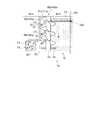
図1は、本発明の第1の実施形態に係る汚泥脱水システム10の全体構成を示す側面図であり、図2は、図1に示す汚泥脱水システム10を構成する濃縮装置12の平面図である。本実施形態に係る汚泥脱水システム10は、上段の濃縮装置12で汚泥(例えば、下水汚泥)をろ過濃縮して脱水した後、下段の脱水装置14でさらに加圧脱水することにより脱水ケーキとして排出する汚泥処理設備である。
1. Description of Overall Configuration of Sludge Dewatering System FIG. 1 is a side view showing the overall configuration of thesludge dewatering system 10 according to the first embodiment of the present invention, and FIG. 2 shows thesludge dewatering system 10 shown in FIG. It is a top view of theconcentration apparatus 12 to perform. In thesludge dewatering system 10 according to this embodiment, sludge (for example, sewage sludge) is filtered and concentrated by theupper concentration device 12 and then dehydrated, and then discharged as a dehydrated cake by further pressure dehydration by thelower dewatering device 14. It is a sludge treatment facility.

汚泥脱水システム10は、無端軌道で走行するろ布ベルト(ろ布)16の上面16aで汚泥を重力ろ過(重力濃縮)するろ過部18を備えた濃縮装置12と、濃縮装置12で濃縮された汚泥を一対のろ布ベルト(ろ布)20,22間で挟持しながら搬送し、加圧脱水する脱水装置14とを備える。濃縮装置12には、汚泥から排出されるろ液を回収し、当該濃縮装置12の上流側位置に返送するろ液回収器23が並設されている。また、濃縮装置12の直前には、当該汚泥脱水システム10の前段設備から搬送され、高分子凝集剤(第1の薬剤)F1を汚泥中に混合するための凝集混和槽24が設けられている。高分子凝集剤F1としては、一般に公知のものを用いればよく、例えば、アニオン性高分子凝集剤やカチオン性高分子凝集剤が挙げられる。  Thesludge dewatering system 10 is concentrated by aconcentrator 12 having afiltration unit 18 that gravity filters (gravity concentration) sludge on theupper surface 16a of a filter cloth belt (filter cloth) 16 that travels in an endless track, and theconcentrator 12 concentrates thesludge dewatering system 10. Adewatering device 14 that conveys sludge between a pair of filter cloth belts (filter cloths) 20 and 22 and dewaters under pressure is provided. Theconcentrator 12 is provided with afiltrate collector 23 that collects the filtrate discharged from the sludge and returns it to the upstream position of theconcentrator 12. Further, immediately before the concentratingdevice 12, there is provided a flocculation /mixing tank 24 which is transported from the previous stage equipment of thesludge dewatering system 10 and mixes the polymer flocculant (first chemical) F1 in the sludge. . As the polymer flocculant F1, generally known ones may be used, and examples thereof include an anionic polymer flocculant and a cationic polymer flocculant.

1.1 濃縮装置の説明
先ず、濃縮装置12について説明する。
1.1 Description of Concentration Device First, theconcentration device 12 will be described.

図1及び図2に示すように、濃縮装置12は、凝集混和槽24からろ布ベルト16の上面16aに投入された汚泥を重力ろ過するろ過部(濃縮部)18と、ろ過部18で重力ろ過された汚泥を1次脱水ローラ(加圧ローラ)26によって加圧脱水して下段の脱水装置14へと排出する加圧部(1次脱水部)28とを備える。ろ過部18の途中には、ろ布ベルト16による搬送方向と交差(図2では直交)する方向に汚泥を移動させる移動機構30が設けられている。  As shown in FIG. 1 and FIG. 2, the concentratingdevice 12 includes a filtration unit (concentration unit) 18 that gravity-filters sludge charged from the flocculation /mixing tank 24 onto theupper surface 16 a of thefilter cloth belt 16, and gravity by thefiltration unit 18. A pressure depressurization unit (primary dehydration unit) 28 is provided which depressurizes and dehydrates the filtered sludge by a primary dehydration roller (pressure roller) 26 and discharges the sludge to thelower dehydration device 14. A movingmechanism 30 that moves sludge in a direction that intersects (orthogonally in FIG. 2) the conveying direction by thefilter cloth belt 16 is provided in the middle of thefiltering unit 18.

ろ過部18は、複数のローラ19a,19b,19c,19d,19eに巻き掛けられ、一方向に周回駆動される無端状のろ布ベルト16の上面(外周面)16aで構成され、ローラ19a,19e間に張られたろ布ベルト16の上面16aに汚泥が載置されることで、該汚泥に含まれる水分を重力によってろ過分離する手段である。  Thefiltration unit 18 is composed of an upper surface (outer peripheral surface) 16a of an endlessfilter cloth belt 16 that is wound around a plurality ofrollers 19a, 19b, 19c, 19d, and 19e and driven to rotate in one direction. The sludge is placed on theupper surface 16a of thefilter cloth belt 16 stretched between 19e, so that water contained in the sludge is filtered and separated by gravity.

ろ布ベルト16は、例えば、通水性を持った長尺帯状の織物や、微細な孔部が網目状に複数形成された長尺帯状の金属スクリーン等のろ布によって構成される。ろ布ベルト16は、十分な張力で各ローラ19a〜19eに巻き掛けられており、図示しないモータ等の駆動源により、図1中に示す矢印の方向(図1では反時計方向)に走行可能である。図1及び図2において、右側(上流側)から左側(下流側)に向かう方向が濃縮装置12での汚泥の搬送方向となる。  Thefilter cloth belt 16 is made of, for example, a filter cloth such as a long belt-like fabric having water permeability, or a long belt-like metal screen in which a plurality of fine holes are formed in a mesh shape. Thefilter cloth belt 16 is wound around therollers 19a to 19e with sufficient tension, and can be driven in the direction of the arrow shown in FIG. 1 (counterclockwise in FIG. 1) by a drive source such as a motor (not shown). It is. 1 and 2, the direction from the right side (upstream side) to the left side (downstream side) is the sludge transport direction in theconcentrator 12.

従って、ろ過部18の上流位置に凝集混和槽24の出口ポート24aから投入・載置された汚泥は、ろ布ベルト16によって下流側へと搬送されつつ、汚泥に含まれる水分が重力によってろ布ベルト16を透過してろ過脱水される。ろ過されたろ液(分離液)は、ろ液回収器23を構成するろ液受皿32aによって回収される。  Therefore, the sludge thrown in and placed from theoutlet port 24a of the flocculation /mixing tank 24 at the upstream position of thefiltration unit 18 is conveyed to the downstream side by thefilter cloth belt 16, and the moisture contained in the sludge is filtered by gravity. It passes through thebelt 16 and is filtered and dehydrated. The filtered filtrate (separated liquid) is collected by afiltrate receiving tray 32 a that constitutes thefiltrate collector 23.

ろ過部18を構成するろ布ベルト16の上面16aには、複数本(図2では、移動機構30の前後に合計12本の構成を例示)の棒体34が立設されている。棒体34は、ろ布ベルト16上を搬送される汚泥に当接して分散させ、その水切りを促進するための障害物であり、その設置位置や本数、形状等は、適宜変更可能である。なお、スクリュー40a,40bの上流側に設置されている棒体34については、その一部を1次脱水ローラ26と同様なローラ(図示せず)に置き換えてもよい。その場合、該ローラとろ布ベルト16の間には若干の隙間を設けるとよく、該ローラは脱水用としてではなく簡易的な水切り用として用いられる。該ローラは複数あっても構わない。  On theupper surface 16a of thefilter cloth belt 16 constituting thefiltration unit 18, a plurality of rod bodies 34 (a total of twelve configurations are illustrated before and after the movingmechanism 30 in FIG. 2) are erected. Therod 34 is an obstacle for abutting and dispersing the sludge transported on thefilter cloth belt 16 to promote draining of the sludge, and its installation position, number, shape and the like can be appropriately changed. Note that a part of therod body 34 installed on the upstream side of thescrews 40 a and 40 b may be replaced with a roller (not shown) similar to theprimary dewatering roller 26. In that case, it is preferable to provide a slight gap between the roller and thefilter cloth belt 16, and the roller is used not for dehydration but for simple draining. There may be a plurality of the rollers.

ろ過部18における移動機構30の上流側には、搬送される汚泥に対して鉄系の無機凝集剤(第2の薬剤)F2を添加する第2薬注装置(薬注装置、薬剤添加装置)36が設けられている。第2薬注装置36は、無機凝集剤F2を貯留する薬品タンク36aと、薬品タンク36aの出口から2方弁36bで分岐した第1ライン36c及び第2ライン36dとを備える。無機凝集剤F2としては、一般に公知のものを用いればよく、例えば、鉄系やアルミ系のものが挙げられる。  A second chemical injection device (chemical injection device, chemical addition device) for adding an iron-based inorganic flocculant (second chemical) F2 to the sludge to be conveyed on the upstream side of the movingmechanism 30 in thefiltration unit 18. 36 is provided. The secondchemical injection device 36 includes achemical tank 36a for storing the inorganic flocculant F2, and afirst line 36c and asecond line 36d branched from the outlet of thechemical tank 36a by a two-way valve 36b. As the inorganic flocculant F2, generally known ones may be used, and examples thereof include iron-based and aluminum-based ones.

図2に示すように、本実施形態では、第1ライン36aをさらに並列に2本に分岐させ、これら2本の第1ライン36c,36cを移動機構30の上流位置でろ布ベルト16の幅方向に渡って延在させ、ろ布ベルト16の両側部近傍にそれぞれ添加ノズル36eを設けている。勿論、第1ライン36aを分岐させずに1本のままで用いてもよい。図1中に破線で示すように、第2ライン36dは、凝集混和槽24へと投入される汚泥に無機凝集剤F2を添加可能に配設されており、図示はしないが第1ライン36cの添加ノズル36eと同様な構成でよい。本実施形態の通常の運転状態では、図示しない制御装置の制御下に、2方弁36bは第1ライン36c側に切換制御されている。2方弁36bの切換は、処理対象となる汚泥の性状等に応じて適宜行なえばよく、後述する2方弁38bについても同様である。  As shown in FIG. 2, in the present embodiment, thefirst line 36 a is further branched into two in parallel, and the twofirst lines 36 c and 36 c are arranged in the width direction of thefilter cloth belt 16 at the upstream position of the movingmechanism 30. Theaddition nozzles 36e are provided in the vicinity of both side portions of thefilter cloth belt 16, respectively. Of course, thefirst line 36a may be used as it is without branching. As indicated by a broken line in FIG. 1, thesecond line 36d is arranged so that the inorganic flocculant F2 can be added to the sludge charged into theflocculation mixing tank 24. Although not shown, thesecond line 36d The configuration may be the same as that of theaddition nozzle 36e. In the normal operation state of the present embodiment, the two-way valve 36b is controlled to be switched to thefirst line 36c side under the control of a control device (not shown). The switching of the two-way valve 36b may be appropriately performed according to the properties of sludge to be treated, and the same applies to the two-way valve 38b described later.

一方、上記した高分子凝集剤F1は、本実施形態の通常の運転状態では、第1薬注装置(薬剤添加装置)38によって凝集混和槽24に投入される直前の汚泥に添加される。第1薬注装置38は、高分子凝集剤F1を貯留する薬品タンク38aと、薬品タンク38aの出口から2方弁38bで分岐した第1ライン38c及び第2ライン38dとを備える。  On the other hand, the above-described polymer flocculant F1 is added to the sludge immediately before being put into theagglomeration mixing tank 24 by the first chemical injection device (drug addition device) 38 in the normal operation state of the present embodiment. The firstchemical injection device 38 includes achemical tank 38a for storing the polymer flocculant F1, and afirst line 38c and asecond line 38d branched from the outlet of thechemical tank 38a by a two-way valve 38b.

図1に示すように、第1ライン38cは、凝集混和槽24へと投入される汚泥に対し、第2薬注装置36の第2ライン36dの下流位置で高分子凝集剤F1を添加可能に配設されている。図2中に破線で示すように、第2ライン38dは、第2薬注装置36の第1ライン36dの上流位置でろ布ベルト16の幅方向に渡って延在し、ろ布ベルト16の両側部近傍にそれぞれ添加ノズル38eが設けられている。本実施形態の通常の運転状態では、図示しない制御装置の制御下に、2方弁38bは第1ライン38c側に切換制御されている。  As shown in FIG. 1, thefirst line 38c can add the polymer flocculant F1 to the sludge charged into theflocculation mixing tank 24 at a position downstream of thesecond line 36d of the secondchemical injection device 36. It is arranged. As shown by a broken line in FIG. 2, thesecond line 38 d extends across the width direction of thefilter cloth belt 16 at the upstream position of thefirst line 36 d of the secondchemical injection device 36, and both sides of thefilter cloth belt 16. Anaddition nozzle 38e is provided in the vicinity of each portion. In the normal operating state of the present embodiment, the two-way valve 38b is controlled to be switched to thefirst line 38c side under the control of a control device (not shown).

通常の運転時、第1薬注装置38からの高分子凝集剤F1が添加された汚泥が導入される凝集混和槽24は、汚泥が貯留されるタンク24bと、タンク24b内の汚泥をモータ24cを駆動源として攪拌する攪拌羽根24dとを備える。攪拌羽根24dによってタンク24b内で高分子凝集剤F1が十分に混合された汚泥は、出口ポート24aからろ布ベルト16の上面16aに投入される。  During normal operation, thecoagulation mixing tank 24 into which the sludge to which the polymer flocculant F1 is added from the firstchemical injection device 38 is introduced has atank 24b in which the sludge is stored, and the sludge in thetank 24b to themotor 24c. And astirring blade 24d for stirring. The sludge in which the polymer flocculant F1 is sufficiently mixed in thetank 24b by thestirring blade 24d is put into theupper surface 16a of thefilter cloth belt 16 from theoutlet port 24a.

次に、このようなろ過部18の途中に設けられる移動機構30は、ろ布ベルト16上を搬送される汚泥を交差方向に移動させつつ、その幅方向寸法を縮小すると同時に汚泥高さを高くすることで圧密し、第2薬注装置36によって添加された無機凝集剤F2を十分に混練する。これにより、濃縮装置12及び脱水装置14での汚泥のろ過効率を向上させ、汚泥濃度を高めることを可能とする。  Next, the movingmechanism 30 provided in the middle of thefiltering unit 18 moves the sludge conveyed on thefilter cloth belt 16 in the crossing direction, while reducing the width direction size and simultaneously increasing the sludge height. By doing so, the inorganic flocculant F2 added by the secondchemical injection device 36 is sufficiently kneaded. Thereby, the filtration efficiency of the sludge in theconcentration apparatus 12 and thedehydration apparatus 14 can be improved, and the sludge concentration can be increased.

移動機構(スクリューコンベア)30は、ろ布ベルト16の上面16aの上流側全面に向かって開口して汚泥を受け入れ可能となっており、ろ布ベルト16による搬送方向と直交する方向に汚泥を移動させる一対のスクリュー40a,40bと、スクリュー40a,40bの下流側に近接配置され、ろ布ベルト16の幅方向両端側にそれぞれ起立配置された一対の案内板42a,42bとを備える。移動機構30では、案内板42a,42b間の隙間(各スクリュー40a,40b間の隙間と略同一)が、当該移動機構30から下流側へと汚泥を排出するための通路(汚泥通路43)となっている。  The moving mechanism (screw conveyor) 30 opens toward the entire upstream surface of theupper surface 16a of thefilter cloth belt 16 so as to accept the sludge, and moves the sludge in a direction perpendicular to the conveying direction by thefilter cloth belt 16. And a pair ofguide plates 42a and 42b that are disposed close to the downstream side of thescrews 40a and 40b and are erected on both ends in the width direction of thefilter cloth belt 16, respectively. In the movingmechanism 30, a gap between theguide plates 42 a and 42 b (substantially the same as the gap between thescrews 40 a and 40 b) and a passage (sludge passage 43) for discharging sludge downstream from the movingmechanism 30. It has become.

スクリュー40a,40bは、ろ布ベルト16による汚泥の搬送方向と直交する方向に延びて該ろ布ベルト16を幅方向に渡るスクリュー軸44と、スクリュー軸44の中央付近を除く両側方の外周面にそれぞれらせん状に設けられたスクリュー羽根41a,41bとを有する。  Thescrews 40a and 40b extend in a direction orthogonal to the sludge transport direction by thefilter cloth belt 16 and extend across thefilter cloth belt 16 in the width direction, and outer peripheral surfaces on both sides except for the vicinity of the center of thescrew shaft 44. And screwblades 41a and 41b provided in a spiral shape.

スクリュー軸44は、図示しない軸受によって両端部がろ布ベルト16の幅方向外側位置で軸支され、例えば、ろ布ベルト16を巻き掛けたローラ19aに対し、チェーンやベルト等の可撓性動力伝達部材39(図1中の2点鎖線参照)によって連係されることで、ろ布ベルト16の走行に伴って回転可能である。ろ布ベルト16の走行動作とスクリュー軸44の回転動作とを同期させる構成とすると、可撓性動力伝達部材39を巻き掛ける各軸の径を適宜設計し又は図示しない減速装置等を搭載することにより、ろ布ベルト16による汚泥の搬送速度と、スクリュー軸44の回転速度(つまり、スクリュー40a,40bによる汚泥の移動速度)との関係を容易に設定・制御することができる。勿論、スクリュー軸44を独自に回転駆動するモータ等の駆動源を設けてもよい。  Both ends of thescrew shaft 44 are pivotally supported at positions outside thefilter cloth belt 16 in the width direction by a bearing (not shown). For example, a flexible power such as a chain or a belt is applied to theroller 19a around which thefilter cloth belt 16 is wound. By being linked by the transmission member 39 (see the two-dot chain line in FIG. 1), it can be rotated as thefilter cloth belt 16 travels. When the traveling operation of thefilter cloth belt 16 and the rotation operation of thescrew shaft 44 are synchronized, the diameter of each shaft around which the flexiblepower transmission member 39 is wound is appropriately designed, or a reduction device (not shown) is mounted. Thus, the relationship between the sludge conveyance speed by thefilter cloth belt 16 and the rotation speed of the screw shaft 44 (that is, the sludge movement speed by thescrews 40a and 40b) can be easily set and controlled. Of course, a drive source such as a motor that independently rotates thescrew shaft 44 may be provided.

各スクリュー40a,40bを構成するスクリュー羽根41a,41bは、ろ布ベルト16の幅方向両側方に寄った位置でスクリュー軸44の外周面にそれぞれ設けられ、互いの先端同士が案内板42a,42b間の隙間と同程度の隙間を介して対向している。各スクリュー羽根41a,41bのらせんの方向は、ろ布ベルト16の中心線で対照形状(逆向き)となっており、各スクリュー40a,40bによる汚泥の移動方向は、それぞれ反対方向に設定されている。このため、各スクリュー40a,40bは、互いにろ布ベルト16の幅方向で外側から内側(中央)に向かって汚泥を移動させ、その先端同士が前記隙間を介して離間した中央部では、両外側から移動された汚泥同士が互いに押し合って圧密され、無機凝集剤F2が汚泥中で十分に混練される。各スクリュー40a,40bは、共通のスクリュー軸44を用いた構成ではなく、それぞれ個別のスクリュー軸を用いた構成としてもよい。  Thescrew blades 41a and 41b constituting thescrews 40a and 40b are respectively provided on the outer peripheral surface of thescrew shaft 44 at positions close to both sides in the width direction of thefilter cloth belt 16, and the tip ends of thescrew blades 41a and 41b areguide plates 42a and 42b. It faces through a gap of the same degree as the gap between them. The direction of the spiral of eachscrew blade 41a, 41b is a contrast shape (reverse direction) at the center line of thefilter cloth belt 16, and the direction of sludge movement by eachscrew 40a, 40b is set in the opposite direction. Yes. For this reason, eachscrew 40a, 40b moves sludge from the outer side toward the inner side (center) in the width direction of thefilter cloth belt 16, and at the center part where the tips are separated from each other via the gap, both outer sides The sludge moved from the above is pressed against each other to be compacted, and the inorganic flocculant F2 is sufficiently kneaded in the sludge. Eachscrew 40a, 40b is good also as a structure using each screw shaft instead of the structure using thecommon screw shaft 44. FIG.

本実施形態の場合、スクリュー軸44の中央部、つまり各スクリュー40a,40b間で露出したスクリュー軸44の外周面に、ろ布ベルト16の幅方向中央側を搬送されてきた汚泥と、一対のスクリュー40a,40bによって中央に圧密された汚泥とを下流側へと円滑に排出するためのパドル45が複数枚設けられている。パドル45は、例えば、スクリュー軸44の外周面に周方向に沿って数枚一組で設けられた羽根車である。  In the case of the present embodiment, the sludge that has been conveyed on the center side in the width direction of thefilter cloth belt 16 to the central portion of thescrew shaft 44, that is, the outer peripheral surface of thescrew shaft 44 exposed between thescrews 40a and 40b, and a pair of A plurality ofpaddles 45 for smoothly discharging the sludge consolidated in the center by thescrews 40a, 40b to the downstream side are provided. Thepaddle 45 is, for example, an impeller provided in pairs on the outer peripheral surface of thescrew shaft 44 along the circumferential direction.

案内板42a,42bは、スクリュー40a,40bの下流側であって該スクリュー40a,40bと近接する位置で起立した壁部46と、壁部46の下端をろ布ベルト16による汚泥の搬送方向で上流側へと湾曲させて突出させることでスクリュー40a,40bの下方略半分を覆う底部47とを有する。各案内板42a,42bの中央側の端部には、ろ布ベルト16による汚泥の搬送方向に沿って下流側へと延びた一対の通路板48a,48bがそれぞれ設けられている。各案内板42a,42b間の隙間は、各スクリュー40a,40bによる汚泥の移動方向で前方側に位置しており、この隙間が下流側へと汚泥を排出するための汚泥通路43を形成している。  Theguide plates 42a and 42b are provided on the downstream side of thescrews 40a and 40b and at a position close to thescrews 40a and 40b. It has abottom portion 47 that covers the lower half of thescrews 40a and 40b by curving and projecting toward the upstream side. A pair ofpassage plates 48a and 48b extending downstream along the sludge transport direction by thefilter cloth belt 16 are provided at the center ends of theguide plates 42a and 42b, respectively. The gap between theguide plates 42a and 42b is located on the front side in the direction of sludge movement by thescrews 40a and 40b, and this gap forms asludge passage 43 for discharging the sludge downstream. Yes.

壁部46は、スクリュー40a,40bの高さと同程度の高さに設定される板状部材であり、その高さは適宜変更可能である。底部47は、図1に示すように、壁部46の下端から搬送方向で上流側に向かって、スクリュー40a,40bの略中心となる位置まで突出形成される板状部材であり、その長さは適宜変更可能である。案内板42a,42bを構成する壁部46や底部47には、微細な孔部を多数形成したスクリーン等を用いてもよい。  Thewall portion 46 is a plate-like member set to a height approximately equal to the height of thescrews 40a and 40b, and the height can be changed as appropriate. As shown in FIG. 1, thebottom portion 47 is a plate-like member that protrudes from the lower end of thewall portion 46 toward the upstream side in the transport direction to a position that is approximately the center of thescrews 40 a and 40 b, and has a length. Can be appropriately changed. For thewall portion 46 and thebottom portion 47 constituting theguide plates 42a and 42b, a screen or the like in which many fine holes are formed may be used.

各通路板48a,48bは、スクリュー羽根41a,41b間や案内板42a,42b間に形成される隙間と同幅の隙間を挟んで互いに対面するように起立設置されている。通路板48a,48bは、スクリュー40a,40bによってろ布ベルト16の中央付近に圧密された汚泥を、下流側への円滑に排出するための通路を形成する壁部材であり、壁部46と同程度の高さに設定される。なお、実際上、スクリュー40a,40bによって中央に圧密された汚泥は、ろ布ベルト16の走行により、一対の案内板42a,42b(壁部46)間に形成された汚泥通路43から下流側へと搬送されるため、通路板48a,48bは省略することもできるが、通路板48a,48bを設けると、中央に圧密され、高さを増した汚泥を下流側へとより円滑に搬送することができる。  Thepassage plates 48a and 48b are erected so as to face each other with a gap having the same width as the gap formed between thescrew blades 41a and 41b and between theguide plates 42a and 42b. Thepassage plates 48a and 48b are wall members that form a passage for smoothly discharging sludge, which is compacted near the center of thefilter cloth belt 16 by thescrews 40a and 40b, to the downstream side. Set to a height of about. In practice, the sludge consolidated in the center by thescrews 40a and 40b is moved downstream from thesludge passage 43 formed between the pair ofguide plates 42a and 42b (wall portion 46) by the traveling of thefilter cloth belt 16. Thepassage plates 48a and 48b can be omitted. However, if thepassage plates 48a and 48b are provided, the sludge that has been consolidated in the center and increased in height can be more smoothly conveyed to the downstream side. Can do.

加圧部28は、濃縮装置12の下方に配置された脱水装置14の前段脱水部(1次脱水部)を構成するものであり、ろ布ベルト16に対してその外周面が圧接配置される1次脱水ローラ26を備える。  The pressurizingunit 28 constitutes a pre-stage dehydrating unit (primary dehydrating unit) of the dehydratingdevice 14 disposed below the concentratingdevice 12, and an outer peripheral surface thereof is pressed against thefilter cloth belt 16. Aprimary dewatering roller 26 is provided.

ろ過部18でろ過濃縮されると共に、移動機構30で無機凝集剤F2が十分に混練され、圧密によって高さを増した汚泥は、加圧部28で1次脱水ローラ26とろ布ベルト16との間で加圧脱水された後、加圧部28の出口(濃縮装置12の出口)から排出・落下され、次工程の脱水装置14に投入される。加圧部28は、移動機構30で圧密されて中央に集合させられた汚泥を潰し、ろ布ベルト16の幅方向に再び拡大させた状態で脱水装置14に送り出すことで、該脱水装置14に投入される汚泥の脱水面積を拡大させ、ここでの脱水効率を向上させる機能も有する。加圧部28で脱水され、ろ布ベルト16を透過したろ液は、ろ液回収器23を構成するろ液受皿32bにより回収される。ろ液受皿32bは、加圧部28から排出されるろ液をトラップできる範囲に設けられればよく、ろ過部18からのろ液がある程度混入しても特に問題とはならない。  The sludge that has been filtered and concentrated by thefiltration unit 18 and sufficiently mixed with the inorganic flocculant F2 by the movingmechanism 30 and increased in height by compaction is separated between theprimary dewatering roller 26 and thefilter cloth belt 16 by thepressurization unit 28. After the pressure dehydration between the two, it is discharged / dropped from the outlet of the pressurizing unit 28 (the outlet of the concentrating device 12), and put into the dehydratingdevice 14 in the next step. The pressurizingunit 28 crushes the sludge that has been consolidated by the movingmechanism 30 and gathered in the center, and sends it to the dehydratingdevice 14 in a state where it has been expanded again in the width direction of thefilter cloth belt 16. It also has a function of increasing the dewatering area of the sludge to be added and improving the dewatering efficiency here. The filtrate that has been dehydrated by the pressurizingunit 28 and permeated through thefilter cloth belt 16 is collected by afiltrate receiving tray 32 b that constitutes thefiltrate collection device 23. Thefiltrate receiving tray 32b only needs to be provided in a range in which the filtrate discharged from the pressurizingunit 28 can be trapped. Even if the filtrate from thefiltering unit 18 is mixed to some extent, there is no particular problem.

図1に示すように、加圧部28と、その下方の脱水装置14との間には、傾斜板49が配設されている。傾斜板49は、濃縮装置12から排出・落下した汚泥を、脱水装置14の投入位置となるろ布ベルト22上へと円滑に導くためのガイドである。  As shown in FIG. 1, aninclined plate 49 is disposed between the pressurizingunit 28 and the dehydratingdevice 14 below the pressurizingunit 28. Theinclined plate 49 is a guide for smoothly guiding the sludge discharged / dropped from the concentratingdevice 12 onto thefilter cloth belt 22 serving as a loading position of the dehydratingdevice 14.

1.2 脱水装置の説明
次に、脱水装置14について説明する。
1.2 Description of Dehydration Device Next, thedehydration device 14 will be described.

図1に示すように、脱水装置(2次脱水部)14は、濃縮装置12の出口から傾斜板49を介して投入された汚泥を一対のろ布ベルト20,22間で搬送しながら加圧脱水する脱水部50と、脱水部50で脱水された汚泥をさらに加圧し圧搾する圧搾部52とを備え、一般的なベルトプレス型脱水機と略同様な構成である。  As shown in FIG. 1, the dewatering device (secondary dewatering unit) 14 pressurizes the sludge introduced from the outlet of the concentratingdevice 12 through theinclined plate 49 while being conveyed between the pair offilter cloth belts 20 and 22. A dehydratingunit 50 for dehydrating and apressing unit 52 for further pressurizing and compressing the sludge dehydrated by the dehydratingunit 50 have substantially the same configuration as a general belt press type dehydrator.

下側のろ布ベルト20は、例えば、通水性を持った長尺帯状の織物や、微細な孔部が網目状に複数形成された長尺帯状の金属スクリーン等のろ布によって構成される。ろ布ベルト20は、十分な張力で複数のローラ21a,21b,21c,21d,21e,21f,21g,21h,21i,21j,21k,21l,21m,21n間に巻き掛けられており、図示しないモータ等の駆動源により、図1中に示す矢印の方向(図1では時計方向)に走行可能である。  The lowerfilter cloth belt 20 is made of, for example, a filter cloth such as a long belt-like fabric having water permeability or a long belt-like metal screen in which a plurality of fine holes are formed in a mesh shape. Thefilter cloth belt 20 is wound between a plurality ofrollers 21a, 21b, 21c, 21d, 21e, 21f, 21g, 21h, 21i, 21j, 21k, 21l, 21m, 21n with sufficient tension, not shown. A drive source such as a motor can travel in the direction of the arrow shown in FIG. 1 (clockwise in FIG. 1).

略同様に、上側のろ布ベルト22についても、例えば、通水性を持った長尺帯状の織物や、微細な孔部が網目状に複数形成された長尺帯状の金属スクリーン等のろ布によって構成される。ろ布ベルト22は、十分な張力で複数のローラ21o,21b,21c,21d,21e,21f,21g,21h,21i,21j,21p,21q間に巻き掛けられており、図示しないモータ等の駆動源により、図1中に示す矢印の方向(図1では反時計方向)に走行可能である。  In a similar manner, the upperfilter cloth belt 22 is made of, for example, a filter cloth such as a long belt-like fabric having water permeability or a long belt-like metal screen having a plurality of fine holes formed in a mesh shape. Composed. Thefilter cloth belt 22 is wound between a plurality ofrollers 21o, 21b, 21c, 21d, 21e, 21f, 21g, 21h, 21i, 21j, 21p, and 21q with sufficient tension, and is driven by a motor or the like (not shown). The vehicle can travel in the direction of the arrow shown in FIG. 1 (counterclockwise in FIG. 1).

ローラ21b〜21i間での下のろ布ベルト20と上のろ布ベルト22との外周面(表面)同士を上下に蛇行させながら当接(又は近接)配置した部分が、脱水部50を構成しており、この間で汚泥は十分に加圧脱水される。また、ローラ21j,21p間での下のろ布ベルト20と上のろ布ベルト22との外周面(表面)同士を当接(又は近接)配置した部分が、圧搾部52を構成しており、圧搾ローラとなるローラ21j,21p間で汚泥はさらに加圧されて圧搾され、所望の水分率の脱水ケーキとなって外部に排出される。  A portion where the outer peripheral surfaces (surfaces) of the lowerfilter cloth belt 20 and the upperfilter cloth belt 22 between therollers 21b to 21i are in contact (or close) while meandering up and down constitutes thedewatering unit 50. During this time, the sludge is sufficiently pressurized and dehydrated. Moreover, the part which contact | abutted (or adjoined) the outer peripheral surface (surface) of the lowerfilter cloth belt 20 and the upperfilter cloth belt 22 between therollers 21j and 21p comprises thepressing part 52. The sludge is further pressurized and pressed between therollers 21j and 21p serving as pressing rollers, and is discharged to the outside as a dehydrated cake having a desired moisture content.

脱水装置14の入口付近には、濃縮装置12の出口からろ布ベルト20上へと落下・投入された汚泥の高さをある程度均一化させ、ろ布ベルト20,22間に形成された脱水部50の入口50aへと円滑に導入するための均し板51が設けられている。均し板51は、濃縮装置12からろ布ベルト20上への汚泥の落下位置のやや下流側上方に配置され、入口50aに向かって次第に下方に傾斜したプレート部材であり、汚泥を下方に押さえつける方向に付勢された板ばね部材で形成してもよい。  In the vicinity of the inlet of thedewatering device 14, the height of the sludge dropped and introduced from the outlet of the concentratingdevice 12 onto thefilter cloth belt 20 is made uniform to some extent, and a dewatering section formed between thefilter cloth belts 20 and 22. A levelingplate 51 is provided for smooth introduction into the 50inlets 50a. The levelingplate 51 is a plate member that is disposed slightly upstream on the downstream side of the sludge dropping position from the concentratingdevice 12 onto thefilter cloth belt 20, and that is gradually inclined downward toward theinlet 50a and presses the sludge downward. You may form with the leaf | plate spring member urged | biased to the direction.

脱水装置14の出口には、ローラ21jの外周面を走行するろ布ベルト20に近接するように、後端下がりの傾斜姿勢で排出トレイ54が設置されている。脱水ケーキは排出トレイ54上を滑りながら排出される。排出トレイ54の上方には、ローラ21pの外周面を走行するろ布ベルト22に近接するように、後端上がりの傾斜姿勢でスクレバ(掻き取り板)56が設置されている。ローラ21j,21p間から排出トレイ54へと排出されず、上のろ布ベルト22に付着したままの汚泥は、スクレバ56によって掻き取られて排出トレイ54へと排出される。なお、下のろ布ベルト20に付着したままの汚泥は、排出トレイ54によって掻き取られ、そのまま排出トレイ54上を滑り落ちる。  At the outlet of thedewatering device 14, adischarge tray 54 is installed in an inclined posture with the rear end lowered so as to be close to thefilter cloth belt 20 running on the outer peripheral surface of theroller 21 j. The dehydrated cake is discharged while sliding on thedischarge tray 54. Above thedischarge tray 54, a scraper (scraping plate) 56 is installed in an inclined posture with the rear end raised so as to be close to thefilter cloth belt 22 running on the outer peripheral surface of theroller 21p. The sludge that is not discharged to thedischarge tray 54 from between therollers 21j and 21p but remains attached to the upperfilter cloth belt 22 is scraped off by thescriber 56 and discharged to thedischarge tray 54. The sludge that remains attached to the lowerfilter cloth belt 20 is scraped off by thedischarge tray 54 and slides down on thedischarge tray 54 as it is.

このような脱水装置14では、濃縮装置12からろ布ベルト20上に投入された汚泥は、入口50aから脱水部50を構成するろ布ベルト20,22間に引き込まれて挟持・加圧された状態で下流側へと搬送される。この間、汚泥に含まれる水分が両ろ布ベルト20,22による加圧力によってろ布ベルト20を透過してろ過脱水され、さらに圧搾部52で圧搾された後、脱水ケーキとして排出トレイ54上に排出される。これら脱水部50及び圧搾部52でろ過されたろ液(分離液)は、ろ液回収器23を構成するろ液受皿58によって回収される。  In such adewatering device 14, the sludge introduced from the concentratingdevice 12 onto thefilter cloth belt 20 is drawn between thefilter cloth belts 20 and 22 constituting thedewatering unit 50 from theinlet 50 a and is sandwiched and pressurized. In the state, it is conveyed downstream. During this time, the moisture contained in the sludge is filtered and dehydrated through thefilter cloth belt 20 by the pressure applied by the twofilter cloth belts 20 and 22, and further squeezed by the squeezingsection 52, and then discharged onto thedischarge tray 54 as a dehydrated cake. Is done. The filtrate (separated liquid) filtered by the dehydratingunit 50 and the squeezingunit 52 is collected by afiltrate receiving tray 58 that constitutes thefiltrate collecting unit 23.

図1に示すように、本実施形態に係る汚泥脱水システム10では、従来より一般的に用いられているシステムと異なり、濃縮装置12のろ布ベルト16と脱水装置14のろ布ベルト20,22とを兼用とせず、それぞれを独立した無端軌道で走行させる構成としている。このため、前段の濃縮装置12のろ布ベルト16の走行速度と、後段の脱水装置14のろ布ベルト20,22の走行速度とを異なる速度に容易に制御することができる。この場合、濃縮装置12のろ布ベルト16の走行速度よりも、脱水装置14のろ布ベルト20,22の走行速度を遅く設定制御することが好ましい。すなわち、当該汚泥脱水システム10では、濃縮装置12に移動機構30を搭載しているため、従来の濃縮装置に比べて脱水率が大幅に高まっており、その結果、脱水装置14に投入される汚泥の量(ケーキ量)を大幅に減少させることができ、脱水装置14でのろ布ベルト20,22の走行速度を遅くしても、投入される汚泥全量を十分に脱水処理することが可能となっている。そして、脱水装置14でのろ布ベルト20,22の走行速度を遅くすることにより、その脱水時にろ布ベルト20,22間を通る時間を長くすることができ、脱水装置14をコンパクトな構成としつつも、高い脱水性能を得ることができる。  As shown in FIG. 1, in thesludge dewatering system 10 according to the present embodiment, thefilter cloth belt 16 of the concentratingdevice 12 and thefilter cloth belts 20 and 22 of thedewatering device 14 are different from the systems generally used conventionally. It is set as the structure which makes each run by an independent endless track. For this reason, the traveling speed of thefilter cloth belt 16 of theformer concentration device 12 and the traveling speed of thefilter cloth belts 20 and 22 of thesubsequent dewatering device 14 can be easily controlled to different speeds. In this case, it is preferable to set and control the traveling speeds of thefilter cloth belts 20 and 22 of thedehydrator 14 to be lower than the traveling speed of thefilter cloth belt 16 of the concentratingdevice 12. That is, in thesludge dewatering system 10, since the movingmechanism 30 is mounted on the concentratingdevice 12, the dewatering rate is significantly increased as compared with the conventional concentrating device, and as a result, the sludge that is input to thedewatering device 14. The amount of cake (the amount of cake) can be significantly reduced, and even if the traveling speed of thefilter cloth belts 20 and 22 in the dehydratingdevice 14 is slowed down, it is possible to sufficiently dehydrate the total amount of sludge to be charged. It has become. Then, by slowing the traveling speed of thefilter cloth belts 20 and 22 in thedehydrator 14, the time required to pass between thefilter cloth belts 20 and 22 during the dehydration can be lengthened, and thedehydrator 14 has a compact configuration. However, high dewatering performance can be obtained.

1.3 ろ液回収器の説明
次に、ろ液回収器23について説明する。
1.3 Description of the filtrate recovery device Next, thefiltrate recovery device 23 will be described.

図1に示すように、ろ液回収器23は、濃縮装置12に並設されており、ろ過部18及び加圧部28から排出されるろ液をそれぞれ個別に回収するろ液受皿32a,32bと、一方のろ液受皿32bで回収されたろ液をろ過部18の上流側位置へと返送する返送ライン(第1返送ライン)60とを備える。本実施形態の場合、ろ液回収器23は、さらに脱水装置14の脱水部50及び圧搾部52から排出される汚泥を回収するろ液受皿58を備える。  As shown in FIG. 1, thefiltrate collector 23 is provided in parallel with the concentratingdevice 12, andfiltrate receivers 32 a and 32 b that individually collect the filtrate discharged from thefiltration unit 18 and thepressurization unit 28. And the return line (1st return line) 60 which returns the filtrate collect | recovered with onefiltrate receiving tray 32b to the upstream position of thefiltration part 18 is provided. In the case of this embodiment, thefiltrate collection device 23 further includes afiltrate receiving tray 58 that collects sludge discharged from the dehydratingunit 50 and thepressing unit 52 of the dehydratingapparatus 14.

返送ライン60は、その入口側がろ液受皿32bの排出口に接続され、その出口側がろ過部18の上流側位置、本実施形態では凝集混和槽24のタンク24bに接続されており、その途中にポンプ(水ポンプ)62が接続されている。従って、ろ液受皿32bで回収された加圧部28からのろ液は、ポンプ62の動力下に返送ライン60を流れて凝集混和槽24へと投入され、再びろ過部18及び加圧部28へと搬送されて濃縮・脱水処理を受ける。  Thereturn line 60 is connected at its inlet side to the outlet of thefiltrate receiving tray 32b, and at its outlet side is connected to the upstream position of thefiltration unit 18, in this embodiment, thetank 24b of theflocculation mixing tank 24. A pump (water pump) 62 is connected. Accordingly, the filtrate from the pressurizingunit 28 collected by thefiltrate receiving tray 32b flows through thereturn line 60 under the power of thepump 62 and is introduced into thecoagulation mixing tank 24, and again thefiltration unit 18 and the pressurizingunit 28. To be concentrated and dehydrated.

このように、ろ液回収器23は、ろ過部18、加圧部28、脱水装置14から排出されるろ液をそれぞれ個別に回収するろ液受皿32a,32b,58を備え、個別に回収したろ液のうち、ろ液受皿32bで回収される加圧部28からのろ液を返送ライン60から濃縮装置12の前段へと返送する構成となっている。  As described above, thefiltrate collector 23 includes thefiltrate receiving trays 32a, 32b, and 58 that individually collect the filtrate discharged from thefiltration unit 18, the pressurizingunit 28, and the dehydratingapparatus 14, and individually collected. Among the filtrates, the filtrate from the pressurizingunit 28 collected by thefiltrate receiving tray 32b is returned from thereturn line 60 to the previous stage of the concentratingdevice 12.

ところで、本発明者らの実験によれば、上記したろ過部18、加圧部28及び脱水装置14から排出されるろ液を個別に回収して調査したところ、各部(各工程)毎にろ液のSS濃度と量が異なっていた。特に、加圧部28からのろ液は、ろ過部18よりも濃度が大幅に高く且つ量が大幅に少なく、また、脱水装置14からのろ液と比較しても、濃度は大幅に高く且つ量は同程度という結果が得られている。そこで、ろ液回収器23では、汚泥脱水システム10の各部から排出されるろ液のうち、濃度の最も高く量も少ない加圧部28(ろ液受皿32b)からのろ液を選択的に別回収し、返送ライン60によって原液側に返送するものとした。これにより、濃度の高く量も少ないろ液を効率的に回収し、繰り返して処理することができ、システム全体でのSS回収率を大幅に向上させることが可能となっている。加圧部28以外からのろ液、つまりろ過部18及び脱水装置14からのろ液は、共通のろ液受皿によってまとめて回収する構成としてもよい。  By the way, according to the experiments by the present inventors, when the filtrate discharged from thefiltration unit 18, thepressurization unit 28, and thedehydrator 14 was individually collected and investigated, the filtration was performed for each unit (each process). The SS concentration and amount of the liquid were different. In particular, the filtrate from the pressurizingunit 28 has a significantly higher concentration and a significantly smaller amount than thefiltration unit 18, and the concentration is significantly higher than the filtrate from thedehydrator 14. The result is the same amount. Therefore, thefiltrate collector 23 selectively separates the filtrate from the pressurizing unit 28 (filtrate receiving tray 32b) having the highest concentration and the least amount of the filtrate discharged from each part of thesludge dewatering system 10. It was collected and returned to the stock solution side by areturn line 60. As a result, the filtrate having a high concentration and a small amount can be efficiently recovered and repeatedly processed, and the SS recovery rate in the entire system can be greatly improved. The filtrate from other than the pressurizingunit 28, that is, the filtrate from thefiltering unit 18 and the dehydratingdevice 14, may be collected together by a common filtrate receiving tray.

勿論、汚泥の性状や添加される薬剤の種類等によっては各部から排出されるろ液の濃度分布が異なる可能性もある。そこで、図1中に2点鎖線で示すように、ろ液受皿32aによって回収されたろ液を、濃縮装置12の上流側位置(凝集混和槽24)へと返送する別返送ライン64を設けてもよく、略同様に、ろ液受皿58によって回収されたろ液を濃縮装置12の上流側位置(凝集混和槽24)へと返送する別返送ライン66を設けてもよい。図1では、別返送ライン64,66をポンプ62を介して返送ライン60の途中に接続した構成を例示しているが、別返送ライン64,66を図示しない別のポンプ等を介して凝集混和槽24に直接的に接続した構成等としてもよい。  Of course, the concentration distribution of the filtrate discharged from each part may differ depending on the properties of the sludge, the type of the added chemical, and the like. Therefore, as shown by a two-dot chain line in FIG. 1, aseparate return line 64 for returning the filtrate collected by thefiltrate receiving tray 32a to the upstream position (aggregation mixing tank 24) of the concentratingdevice 12 may be provided. It is also possible to provide aseparate return line 66 for returning the filtrate collected by thefiltrate receiving tray 58 to the upstream position of the concentrating device 12 (flocculation mixing tank 24). Although FIG. 1 illustrates a configuration in which theseparate return lines 64 and 66 are connected to thereturn line 60 via thepump 62, theseparate return lines 64 and 66 are coagulated and mixed via another pump (not shown). It is good also as a structure etc. which were directly connected to thetank 24.

2. 汚泥脱水システムの動作及び作用効果の説明
次に、以上のように構成される汚泥脱水システム10の動作及び作用効果について説明する。
2. Next, the operation and effect of thesludge dewatering system 10 will be described.

先ず、当該汚泥脱水システム10で濃縮・脱水する処理対象物である汚泥は、第1薬注装置38の第1ライン38cによって所定の高分子凝集剤F1が添加された状態で凝集混和槽24に導入される。凝集混和槽24のタンク24b内に導入された汚泥は、攪拌羽根24dによって十分に攪拌・混合されてフロック化し、出口ポート24aからろ布ベルト16の上面16aの上流側、つまり濃縮装置12の入口へと投入される。  First, the sludge that is the object to be concentrated and dewatered by thesludge dewatering system 10 is added to theflocculation mixing tank 24 with the predetermined polymer flocculant F1 added by thefirst line 38c of the firstchemical injection device 38. be introduced. The sludge introduced into thetank 24b of theagglomeration mixing tank 24 is sufficiently stirred and mixed by thestirring blade 24d to form a floc, and from theoutlet port 24a to the upstream side of theupper surface 16a of thefilter cloth belt 16, that is, the inlet of the concentratingdevice 12. It is thrown into.

濃縮装置12に投入された汚泥は、走行するろ布ベルト16によってろ過部18を搬送され、途中で棒体34による水切り促進作用を受けながら重力ろ過(重力脱水)される。この間、図2及び図3に示すように、ろ布ベルト16の幅方向で両側方を搬送される汚泥に対し、第2薬注装置36の添加ノズル36eから所定の無機凝集剤F2が滴下されつつ、該汚泥は移動機構30に到達する。  The sludge thrown into the concentratingdevice 12 is conveyed through thefiltration unit 18 by the travelingfilter cloth belt 16 and gravity filtered (gravity dehydration) while receiving a draining promoting action by therod body 34 on the way. During this time, as shown in FIGS. 2 and 3, a predetermined inorganic flocculant F2 is dripped from theaddition nozzle 36e of the secondchemical injection device 36 to the sludge conveyed on both sides in the width direction of thefilter cloth belt 16. Meanwhile, the sludge reaches the movingmechanism 30.

図3に示すように、移動機構30では、ろ布ベルト16の幅方向で両側方を搬送され、無機凝集剤F2が搬送方向に連続する帯状に添加された汚泥は、各スクリュー40a,40bの回転に巻き込まれると、案内板42a,42bによって案内されつつ、中央部に向かって押し込まれながら移動する。この際、回転するスクリュー羽根41a,41bによって一定間隔で切断されつつ移動される小さな汚泥の各塊には、それぞれ無機凝集剤F2が付着している。  As shown in FIG. 3, in the movingmechanism 30, the sludge that is transported on both sides in the width direction of thefilter cloth belt 16 and added with the inorganic flocculant F <b> 2 in a continuous belt shape in the transport direction is supplied to each screw 40 a, 40 b. When it is caught in the rotation, it moves while being pushed toward the center while being guided by theguide plates 42a and 42b. At this time, the inorganic flocculant F2 is attached to each lump of small sludge that is moved while being cut at regular intervals by therotating screw blades 41a and 41b.

無機凝集剤F2を伴いながらスクリュー40a,40bで移動された汚泥は、ろ布ベルト16の中央部(中心部)を搬送されてきた汚泥と混合される。同時に、各スクリュー40a,40bによる押出力によってろ布ベルト16の中央部で汚泥同士が押し潰され合って圧密される。これにより、汚泥は、その幅方向寸法が縮小して高さ(嵩)が増加した状態で、パドル45の回転力も付与されながら汚泥通路43を通って通路板48a,48b間から下流側へと排出され、この間にも、ろ布ベルト16による重力ろ過が継続されて所望の濃縮濃度まで濃縮される。なお、スクリュー40a,40bの前後位置においてもろ布ベルト16が走行しているため、パドル45を省略した構成としても、スクリュー40a,40bによって圧密された汚泥を、案内板42a,42b間の開口部である汚泥通路43から下流側へと円滑に排出することは勿論可能である。  The sludge moved by thescrews 40a and 40b with the inorganic flocculant F2 is mixed with the sludge that has been transported through the central portion (center portion) of thefilter cloth belt 16. At the same time, sludges are crushed and consolidated in the center of thefilter cloth belt 16 by the pressing force of thescrews 40a and 40b. As a result, the sludge is passed through thesludge passage 43 from thepassage plates 48a and 48b to the downstream side while the rotational force of thepaddle 45 is applied while the width direction dimension is reduced and the height (bulk) is increased. During this time, gravity filtration by thefilter cloth belt 16 is continued and concentrated to a desired concentration. In addition, since thefilter cloth belt 16 is running at the front and rear positions of thescrews 40a and 40b, even if thepaddle 45 is omitted, the sludge compacted by thescrews 40a and 40b is used as the opening between theguide plates 42a and 42b. Of course, it is possible to discharge smoothly from thesludge passage 43 to the downstream side.

このような濃縮装置12による濃縮過程において、例えば、図1及び図2に示すように、ろ過部18の入口側にろ布ベルト16の幅方向で幅W1に広がって高さh1で投入された汚泥は、移動機構30から排出される際には、幅W1より狭い幅W2に縮小されるため、その平面視での表面積の低下分だけ高さ方向寸法が増して高さh2となり、十分に圧密された状態となっている。このため、汚泥の濃縮濃度は、一般的な濃縮装置で通常の重力ろ過のみを受けた場合に比べて大幅に高まる。また、移動機構30より下流側では汚泥高さが増しているため、その自重によって重力ろ過の効率が一層向上し、しかも無機凝集剤F2がスクリュー40a,40bによって十分に混練されている。従って、移動機構30までの時点で十分に脱水され濃縮された汚泥であっても、さらに重力ろ過による濃縮を促進することができる。さらに、スクリュー40a,40bで汚泥を中央部へと移動させる際に、案内板42a,42bとスクリュー羽根41a,41bの回転力とによって汚泥が移動しながら圧搾されるため、汚泥の濃縮がさらに高まることになる。この際、スクリュー40a,40bによって圧搾された汚泥の水分は、壁部46から底部47を伝って流れ、ろ布ベルト16によってろ過される。  In the concentration process by theconcentration device 12, for example, as shown in FIGS. 1 and 2, thefilter cloth belt 16 spreads to the width W1 in the width direction of thefilter cloth belt 16 at the inlet side of thefiltration unit 18 and is introduced at a height h1. When the sludge is discharged from the movingmechanism 30, the sludge is reduced to a width W2 that is narrower than the width W1. It is in a consolidated state. For this reason, the concentration concentration of sludge increases significantly compared with the case where it receives only normal gravity filtration with a general concentration apparatus. Further, since the sludge height is increased on the downstream side from the movingmechanism 30, the gravity filtration efficiency is further improved by its own weight, and the inorganic flocculant F2 is sufficiently kneaded by thescrews 40a and 40b. Therefore, even the sludge that has been sufficiently dehydrated and concentrated up to the movingmechanism 30 can further promote concentration by gravity filtration. Further, when the sludge is moved to the central portion by thescrews 40a and 40b, the sludge is compressed while being moved by the rotational force of theguide plates 42a and 42b and thescrew blades 41a and 41b, so that the concentration of the sludge is further increased. It will be. At this time, the moisture of the sludge compressed by thescrews 40 a and 40 b flows from thewall portion 46 through thebottom portion 47 and is filtered by thefilter cloth belt 16.

移動機構30によって圧密された汚泥は、その下流側の棒体34による水切り促進作用を受けつつ、さらに下流側へと搬送されて加圧部28に導入される。加圧部28に導入された汚泥は、1次脱水ローラ26とろ布ベルト16との間で挟持加圧されることで幅W2から幅W3へと広がり、高さh2より低い高さh3となりながら加圧脱水されて排出・落下し、傾斜板49上を滑って脱水装置14に投入される。移動機構30で一旦圧密された汚泥を再び加圧部28で扁平に広げることにより、後工程である脱水装置14での汚泥の脱水面積を拡大し、その脱水効率を向上させることができる。  The sludge consolidated by the movingmechanism 30 is transported further downstream and introduced into the pressurizingunit 28 while receiving drainage promoting action by therod 34 on the downstream side. The sludge introduced into thepressure unit 28 is sandwiched and pressurized between theprimary dewatering roller 26 and thefilter cloth belt 16 so that the sludge spreads from the width W2 to the width W3 and becomes a height h3 lower than the height h2. It is dehydrated under pressure, discharged and dropped, and slid on theinclined plate 49 and put into thedehydrator 14. The sludge once consolidated by the movingmechanism 30 is flattened again by the pressurizingunit 28, whereby the dewatering area of the sludge in thedewatering device 14 which is a subsequent process can be expanded and the dewatering efficiency can be improved.

この加圧部28での脱水時、加圧脱水された汚泥から排出されるろ液は、ろ液受皿32bによってろ過部18からのろ液とは別回収され、ポンプ62の動力下に返送ライン60を流通し、濃縮装置12の前段にある凝集混和槽24に返送される。これにより、SS濃度の高い加圧部28からのろ液を繰り返し濃縮装置12に導入して濃縮・脱水処理することができ、ろ液中のSS回収率を大幅に向上させることができる。  At the time of dehydration in the pressurizingunit 28, the filtrate discharged from the pressure-dehydrated sludge is collected separately from the filtrate from thefilter unit 18 by thefiltrate receiving tray 32 b and returned to the power line of thepump 62. 60 is circulated and returned to theagglomeration mixing tank 24 in the preceding stage of theconcentration apparatus 12. Thereby, the filtrate from thepressurization part 28 with high SS density | concentration can be repeatedly introduce | transduced into theconcentration apparatus 12, and can be concentrated and dehydrated, and SS recovery rate in a filtrate can be improved significantly.

脱水装置14の入口側に落下・投入された汚泥は、走行するろ布ベルト22で搬送されつつ均し板51で均された後、先ず、入口50aから脱水部50へと導入される。脱水部50において、汚泥は、蛇行する上下一対のろ布ベルト20,22間で挟持・加圧されて効率よく脱水されながら搬送され、次に圧搾部52に導入される。圧搾部52において、汚泥は、一対のろ布ベルト20,22間に挟持されつつ、圧搾ローラとなるローラ21j,21p間で強く加圧されて圧搾されて所望の水分率の脱水ケーキとなり、排出トレイ54からシステム外部へと排出される。  The sludge dropped and introduced to the inlet side of thedewatering device 14 is leveled by the levelingplate 51 while being transported by the travelingfilter cloth belt 22, and is first introduced from theinlet 50a into thedewatering unit 50. In thedewatering unit 50, the sludge is nipped and pressurized between a pair of upper and lowerfilter cloth belts 20, 22 that meander and is transported while being efficiently dehydrated, and then introduced into thepressing unit 52. In the squeezingsection 52, the sludge is sandwiched between the pair offilter cloth belts 20 and 22, and is strongly pressed and squeezed between therollers 21j and 21p serving as squeezing rollers to form a dehydrated cake having a desired moisture content, and discharged. The paper is discharged from thetray 54 to the outside of the system.

以上のように、本実施形態に係る汚泥脱水システム10では、ろ布ベルト16の上面16aで汚泥を搬送しながら濃縮する濃縮部であるろ過部18と、ろ過部18を通過した汚泥をろ布ベルト18上で加圧脱水する1次脱水部である加圧部28と、ろ過部18及び加圧部28から排出されるろ液をそれぞれ個別に回収可能なろ液回収器23を備え、ろ液受皿32a,32bによって個別に回収されたろ液のうち、一方のろ液をろ過部18の上流側位置へと返送する返送ライン60を備える。これにより、濃縮装置12の各部から排出されるろ液を、その性状等に応じて適切に別回収することができ、ろ液の処理効率が向上する。さらに、ろ液回収器23は、返送ライン60によって、SS濃度が高いろ液(例えば、加圧部28からのろ液)を選択的に抽出して別回収し、繰り返し濃縮装置12に導入することができる。これにより、ろ液中のSS回収率を大幅に向上させ、最終的に脱水ケーキとして排出される以外の余剰な固形分を可及的に低減することができる。なお、上記実施形態では、返送ライン60をろ過部18の上流側位置として凝集混和槽24に接続する構成を例示したが、返送ライン60からのろ液はろ過部18への汚泥投入部(入口ポート24aからろ布ベルト16への汚泥投入部)付近等に返送してもよく、別返送ライン64,66についても同様である。  As described above, in thesludge dewatering system 10 according to the present embodiment, thefiltration unit 18 that is a concentration unit that concentrates while conveying the sludge on theupper surface 16a of thefilter cloth belt 16, and the sludge that has passed through thefiltration unit 18 is filtered. Apressure unit 28 that is a primary dewatering unit that performs pressure dehydration on thebelt 18, and afiltrate collector 23 that can individually collect the filtrate discharged from thefiltration unit 18 and thepressure unit 28 are provided. Areturn line 60 for returning one of the filtrates individually collected by the receivingtrays 32 a and 32 b to the upstream position of thefiltration unit 18 is provided. Thereby, the filtrate discharged | emitted from each part of theconcentration apparatus 12 can be separately separately collect | recovered according to the property etc., and the processing efficiency of a filtrate improves. Further, thefiltrate collector 23 selectively extracts a filtrate having a high SS concentration (for example, a filtrate from the pressurizing unit 28) through thereturn line 60, separately collects it, and repeatedly introduces it into theconcentration device 12. be able to. Thereby, the SS recovery rate in a filtrate can be improved significantly, and excess solid content other than finally discharged | emitted as a dewatering cake can be reduced as much as possible. In the above embodiment, the configuration in which thereturn line 60 is connected to thecoagulation mixing tank 24 as the upstream position of thefiltration unit 18 is exemplified. However, the filtrate from thereturn line 60 is a sludge input unit (inlet) to thefiltration unit 18. It may be returned to the vicinity of the sludge input part) from theport 24a to thefilter cloth belt 16, and the same applies to theseparate return lines 64 and 66.

汚泥脱水システム10は、さらに、加圧部28を通過した汚泥を加圧脱水する2次脱水部となる脱水装置14を備え、ろ液回収器23は、ろ過部18、加圧部28及び脱水装置14から排出されるろ液のうち、少なくとも1つのろ液を他のろ液と個別に回収して返送ライン60へと流通させる構成としている。これにより、汚泥の濃縮濃度を一層高めることができ、しかも各部から排出されるろ液の処理効率を一層向上させることが可能となっている。  Thesludge dewatering system 10 further includes adewatering device 14 serving as a secondary dewatering unit for pressure dewatering the sludge that has passed through the pressurizingunit 28, and thefiltrate recovery device 23 includes thefiltration unit 18, the pressurizingunit 28, and the dehydration unit Among the filtrates discharged from thedevice 14, at least one filtrate is collected separately from the other filtrates and distributed to thereturn line 60. Thereby, the concentration density | concentration of sludge can be raised further and also the process efficiency of the filtrate discharged | emitted from each part can be improved further.

汚泥脱水システム10では、濃縮装置12において、第1の薬剤が添加され、ろ過部18で重力ろ過されることである程度濃縮された汚泥に第2の薬剤を添加した後、移動機構30でろ布ベルト16の搬送方向と交差する方向に汚泥を移動させることにより、この移動時に汚泥を第2の薬剤と十分に混練し、さらに圧密することができる。これにより、濃縮装置12での汚泥の濃縮・脱水率を向上させ、濃縮濃度を高めることができる。  In thesludge dewatering system 10, the first chemical agent is added in theconcentration device 12, and the second chemical agent is added to the sludge concentrated to some extent by gravity filtration in thefiltration unit 18, and then the filter cloth belt is moved by the movingmechanism 30. By moving the sludge in a direction crossing the 16 conveying direction, the sludge can be sufficiently kneaded with the second chemical and further consolidated during this movement. Thereby, the concentration and dehydration rate of the sludge in theconcentration apparatus 12 can be improved, and concentration concentration can be raised.

汚泥脱水システム10では、移動機構30として、ろ布ベルト16による汚泥の搬送方向と交差する方向に延び、その回転によって汚泥を移動させるスクリュー40a,40bを有し、ろ布ベルト16による汚泥の搬送方向でスクリュー40a,40bの下流側であって該スクリュー40a,40bと近接する位置に、スクリュー40a,40bによる汚泥の移動を案内する案内板42a,42bを起立させている。このため、案内板42a,42bでせき止めながら汚泥をスクリュー40a,40bによって移動させることができ、汚泥を圧搾し、その濃縮濃度を一層高めることができる。  In thesludge dewatering system 10, the movingmechanism 30 includesscrews 40 a and 40 b that extend in a direction intersecting the sludge transport direction by thefilter cloth belt 16 and move the sludge by its rotation. Theguide plates 42a and 42b that guide the movement of sludge by thescrews 40a and 40b are erected at positions downstream of thescrews 40a and 40b in the direction and close to thescrews 40a and 40b. For this reason, sludge can be moved by thescrews 40a and 40b while clogging with theguide plates 42a and 42b, and the sludge can be squeezed and its concentration can be further increased.

3. 第2の実施形態に係る汚泥脱水システムの説明
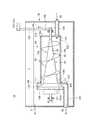
図4は、本発明の第2の実施形態に係る汚泥脱水システム10aの構成を示す側面図である。
3. Description of Sludge Dewatering System According to Second Embodiment FIG. 4 is a side view showing the configuration of thesludge dewatering system 10a according to the second embodiment of the present invention.

図4に示すように、汚泥脱水システム10aは、図1に示す汚泥脱水システム10と比べて、ろ液回収器23と異なる構成のろ液回収器23a及び該ろ液回収器23aに付設された固液分離装置70を備える以外は、略同様な構成である。なお、図4では、脱水装置14について、一部の要素以外は省略し、その構成を簡略化して図示している。  As shown in FIG. 4, thesludge dewatering system 10a is attached to thefiltrate recovery device 23a having a different configuration from thefiltrate recovery device 23 and thefiltrate recovery device 23a as compared to thesludge dewatering system 10 shown in FIG. The configuration is substantially the same except that the solid-liquid separator 70 is provided. In FIG. 4, thedehydrator 14 is omitted except for some elements, and the configuration is simplified.

ろ液回収器23aは、濃縮装置12に並設されており、ろ液受皿32bで回収された加圧部28からのろ液をろ過部18の上流側位置へと返送する返送ライン(第2返送ライン)68を備える。固液分離装置70は、返送ライン68の途中に接続されている。ろ液受皿32bで回収されたろ液は、その全量を固液分離装置70に投入するものとしてよいが、例えば、処理対象となるろ液の総量が多い場合等の諸条件によっては、一部のみを固液分離装置70に導入し、残りをバイパスライン68aによって固液分離装置70をバイパスさせ、その出口側の返送ライン68へと流出させる構成としてもよい。  Thefiltrate recovery unit 23a is arranged in parallel with the concentratingdevice 12, and returns a filtrate line (second line) for returning the filtrate from the pressurizingunit 28 collected by thefiltrate receiving tray 32b to the upstream side position of thefiltration unit 18. Areturn line 68. The solid-liquid separator 70 is connected in the middle of thereturn line 68. The entire amount of the filtrate collected in thefiltrate receiving tray 32b may be put into the solid-liquid separation device 70. For example, depending on various conditions such as when the total amount of filtrate to be treated is large, only a part of the filtrate is collected. May be introduced into the solid-liquid separation device 70, and the remainder may be bypassed by thebypass line 68a and discharged to thereturn line 68 on the outlet side.

固液分離装置70で固液分離されたろ液の固形分は、ポンプ62の動力下に返送ライン68を流れて凝集混和槽24へと投入され、再びろ過部18及び加圧部28へと搬送されて濃縮・脱水処理を受ける。一方、固液分離装置70で固液分離されたろ液の液体分は、液体分排出管71を通って洗浄水貯留槽72に貯留された後、洗浄水ポンプ74の動力下に洗浄水供給ライン76を流れて洗浄ノズル78へと供給される。洗浄ノズル78は、加圧部28で汚泥を排出した後、再び凝集混和槽24から汚泥が投入されるまでの間の位置でろ布ベルト16に洗浄水を噴射して洗浄するためのものである。  The solid content of the filtrate separated by solid-liquid separation by the solid-liquid separation device 70 flows through thereturn line 68 under the power of thepump 62 and is fed into thecoagulation mixing tank 24, and is conveyed again to thefiltration unit 18 and thepressurization unit 28. It is concentrated and dehydrated. On the other hand, the liquid component of the filtrate separated from the solid and the liquid by the solid-liquid separator 70 is stored in the cleaningwater storage tank 72 through theliquid discharge pipe 71 and then the cleaning water supply line under the power of the cleaningwater pump 74. It flows through 76 and is supplied to thewashing nozzle 78. Thewashing nozzle 78 is for injecting washing water onto thefilter cloth belt 16 and washing it at a position between the time when the sludge is discharged by the pressurizingunit 28 and the time when the sludge is again fed from thecoagulation mixing tank 24. .

ろ液回収器23aについても、上記のろ液回収器23の場合と同様、各部から排出されるろ液の濃度分布に対応するために、図4中に2点鎖線で示すように、ろ液受皿32a,58によって回収されたろ液を、固液分離装置70の入口側へと供給する別返送ライン80,82を設けてもよい。また、固液分離装置70で固液分離され、洗浄水貯留槽72に貯留されたろ液の液体分を、洗浄水ポンプ74の動力下に脱水装置14のろ布ベルト20,22を洗浄するための洗浄ノズル84へと供給する洗浄水供給ライン86を設けてもよい。  As in the case of thefiltrate recovery unit 23, thefiltrate recovery unit 23a also has a filtrate as shown by a two-dot chain line in FIG. 4 in order to correspond to the concentration distribution of the filtrate discharged from each part.Separate return lines 80 and 82 for supplying the filtrate collected by the receivingtrays 32a and 58 to the inlet side of the solid-liquid separator 70 may be provided. Further, in order to wash thefilter cloth belts 20 and 22 of thedehydrator 14 with the power of thewashing water pump 74, the liquid component of the filtrate separated by the solid-liquid separation device 70 and stored in the washingwater storage tank 72 is used. A cleaningwater supply line 86 that supplies the cleaningnozzle 84 may be provided.

次に、固液分離装置70について説明する。  Next, the solid-liquid separator 70 will be described.

図5は、別回収したろ液を固液分離する固液分離装置70の全体構成図であり、一部を断面で示した側面図である。固液分離装置70は、ろ液を貯留可能な水槽88と、水槽88内に水没設置されるスクリュープレス型分離機90(以下、単に「分離機90」ともいう)とを備える。  FIG. 5 is an overall configuration diagram of a solid-liquid separation device 70 for solid-liquid separation of the separately collected filtrate, and is a side view partially showing a cross section. The solid-liquid separation device 70 includes awater tank 88 capable of storing filtrate and a screw press type separator 90 (hereinafter also simply referred to as “separator 90”) installed in thewater tank 88.

分離機90は、円筒形状のろ過体92と、ろ過体92の内部に回転可能に設けられたスクリュー94とを備え、ろ過体92の一端側の投入口92aから当該ろ過体92の内部へと投入されたろ液(処理液)を、スクリュー94の回転力によって他端側へと搬送しつつ固形分(濃縮汚泥)と液体分(分離液)とに固液分離する。分離機90で分離された濃縮汚泥は排出口92bから排出され、分離液は水槽88内に流出される。分離機90は、その投入口92a側の一部のみが水槽88内で水没するように傾斜姿勢で設置されてもよい。  Theseparator 90 includes acylindrical filter body 92 and ascrew 94 that is rotatably provided inside thefilter body 92, and enters the inside of thefilter body 92 from aninlet 92 a on one end side of thefilter body 92. The input filtrate (treatment liquid) is solid-liquid separated into solid (concentrated sludge) and liquid (separated liquid) while being conveyed to the other end side by the rotational force of thescrew 94. The concentrated sludge separated by theseparator 90 is discharged from thedischarge port 92b, and the separated liquid flows out into thewater tank 88. Theseparator 90 may be installed in an inclined posture so that only a part on theinlet 92 a side is submerged in thewater tank 88.

スクリュー94は、ろ過体92の軸心と同軸上に延在し、一端側(投入口92a側)から他端側(排出口92b側)に向かって漸次拡径するスクリュー軸96と、スクリュー軸96の外周面にらせん状に設けられたスクリュー羽根98とを有する。  Thescrew 94 extends coaxially with the shaft center of thefilter body 92, and gradually increases in diameter from one end side (inputport 92a side) to the other end side (discharge port 92b side). 96 andscrew blades 98 provided in a spiral shape on the outer peripheral surface.

スクリュー軸96は、例えば、軸受100,101によってその両端部が軸支され、一端側に連結された駆動力伝達機構102によって回転駆動される。図5では、スクリュー軸96及びこれを軸支する軸受100,101を水槽88内で水没させた構成を例示しているが、スクリュー軸96の一方又は両方の端部を水槽88の外部に突出させ、この突出部分を軸受100等で軸支する構成等としてもよい。  Thescrew shaft 96 is rotationally driven by, for example, a drivingforce transmission mechanism 102 supported at both ends bybearings 100 and 101 and connected to one end side. FIG. 5 illustrates a configuration in which thescrew shaft 96 and thebearings 100 and 101 supporting thescrew shaft 96 are submerged in thewater tank 88, but one or both ends of thescrew shaft 96 protrude outside thewater tank 88. The projecting portion may be supported by the bearing 100 or the like.

駆動力伝達機構102は、例えば、濃縮装置12のろ布ベルト16を巻き掛けたローラ19aの回転軸103に対し、チェーンやベルト等の可撓性動力伝達部材によって図示しない減速機構等を伴って連係される(図4及び図5参照)。これにより、駆動力伝達機構102は、ろ過部18及び加圧部28を構成するろ布ベルト16の走行用の駆動源(図示せず)からの駆動力をスクリュー94(スクリュー軸96)に伝達することができる。駆動力伝達機構102は、他のローラ19b〜19eの回転軸に連係されてもよく、ろ布ベルト16の走行用の前記駆動源に直接的に連係されてもよい。また、加圧部28の1次脱水ローラ26が個別の駆動源(図示せず)を有する構成の場合には、該駆動源に連結されてもよく、さらには、脱水装置14の各ローラ21a〜21oの回転軸やろ布ベルト20,22の駆動源(図示せず)に連係させてもよい。勿論、スクリュー軸96を個別に回転駆動する駆動源(図示せず)を設けてもよい。駆動力伝達機構102は、可撓性動力伝達部材と共にギア機構を設けた構成や、ギア機構のみの構成であってもよい。  The drivingforce transmission mechanism 102 is accompanied by a speed reduction mechanism (not shown) or the like by a flexible power transmission member such as a chain or a belt with respect to therotating shaft 103 of theroller 19a around which thefilter cloth belt 16 of the concentratingdevice 12 is wound. They are linked (see FIGS. 4 and 5). Thereby, the drivingforce transmission mechanism 102 transmits a driving force from a driving source (not shown) for running thefilter cloth belt 16 constituting thefiltering unit 18 and the pressurizingunit 28 to the screw 94 (screw shaft 96). can do. The drivingforce transmission mechanism 102 may be linked to the rotation shafts of theother rollers 19b to 19e, or may be linked directly to the driving source for traveling thefilter cloth belt 16. When theprimary dewatering roller 26 of thepressure unit 28 has an individual drive source (not shown), it may be connected to the drive source, and furthermore, eachroller 21a of thedehydrator 14 You may make it link with the drive source (not shown) of the rotating shaft of ~ 21o, and thefilter cloth belts 20 and 22. Of course, you may provide the drive source (not shown) which rotationally drives thescrew shaft 96 separately. The drivingforce transmission mechanism 102 may have a configuration in which a gear mechanism is provided together with a flexible power transmission member, or a configuration having only a gear mechanism.

スクリュー軸96は、上記のように、一端側から他端側に向かって漸次拡径するテーパ形状を有するため、該スクリュー軸96の外周面とろ過体92の内周面との間に形成される空間は、一端側(上流側)から他端側(下流側)に向かって次第に狭くなり、これによりろ液中の固形分を圧搾し、固液分離する。  Since thescrew shaft 96 has a tapered shape that gradually increases in diameter from one end side to the other end side as described above, it is formed between the outer peripheral surface of thescrew shaft 96 and the inner peripheral surface of thefilter body 92. The space is gradually narrowed from one end side (upstream side) to the other end side (downstream side), thereby compressing the solid content in the filtrate and solid-liquid separation.

スクリュー軸96の他端側には、ろ過体92の内部で固液分離された濃縮汚泥を圧密するテーパコーン104が設けられている。テーパコーン104は、スクリュー軸96の外周面に該スクリュー軸96と同軸に設けられ、スクリュー軸96よりも大きな傾斜角度で拡径する傾斜面104aを有する。テーパコーン104は、例えば、スクリュー軸96の外周面に軸方向に移動可能に外挿され、図示しない油圧シリンダやエアシリンダ等の加圧装置によってろ過体92側に向かって付勢されている。  On the other end side of thescrew shaft 96, atapered cone 104 for compacting the concentrated sludge separated into solid and liquid inside thefilter body 92 is provided. The taperedcone 104 is provided on the outer peripheral surface of thescrew shaft 96 coaxially with thescrew shaft 96, and has aninclined surface 104 a that expands in diameter at a larger inclination angle than thescrew shaft 96. For example, thetaper cone 104 is extrapolated on the outer peripheral surface of thescrew shaft 96 so as to be movable in the axial direction, and is biased toward thefilter body 92 by a pressurizing device such as a hydraulic cylinder or an air cylinder (not shown).

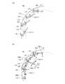
図6は、ろ過体92の一部省略斜視図であり、図面の見易さを確保するため、周方向に複数配列されて当該ろ過体92の外周面を形成するプレート106のうちの一部のみを図示したものである。図7は、ろ過体92を正面側から見た構成図である。  FIG. 6 is a partially omitted perspective view of thefilter body 92, and a part of theplate 106 that is arranged in the circumferential direction and forms the outer peripheral surface of thefilter body 92 in order to ensure the visibility of the drawing. Is only illustrated. FIG. 7 is a configuration diagram of thefilter body 92 as viewed from the front side.

図5〜図7に示すように、ろ過体92は、スクリュー94の一端側(小径側)が挿通された支持板108と、スクリュー94の他端側(大径側)が挿通された支持板109とを備え、これら支持板108,109間に、その周方向に沿って複数(図7では14枚の構成を例示)のプレート106が配列され、各プレート106によって当該ろ過体92の外周面が形成されている。ろ過体92は、例えば水槽88の底面に固定された図示しない基台等によって支持板108,109が支持されることで、水槽88内の所定位置に固定・設置される。  As shown in FIGS. 5 to 7, thefilter body 92 includes asupport plate 108 through which one end side (small diameter side) of thescrew 94 is inserted, and a support plate through which the other end side (large diameter side) of thescrew 94 is inserted. 109, and a plurality of plates 106 (14 configurations are illustrated in FIG. 7) are arranged between thesupport plates 108 and 109 along the circumferential direction, and the outer peripheral surface of thefilter body 92 is arranged by eachplate 106. Is formed. Thefilter body 92 is fixed and installed at a predetermined position in thewater tank 88 by supporting thesupport plates 108 and 109 by, for example, a base (not shown) fixed to the bottom surface of thewater tank 88.

プレート106は、その長手方向がスクリュー軸96の軸方向と平行して配置されると共に、支持板108,109の両内面にそれぞれ突設された回転軸110,111により、長手方向両端面が軸支されている。すなわち、各プレート106は、回転軸110,111を軸中心として回転自由な状態で支持板108,109間に設置されている。一対の回転軸110,111は、互いの軸方向が同軸上となる位置に設けられ、その軸方向はスクリュー軸96の軸方向と平行している。  The longitudinal direction of theplate 106 is arranged in parallel with the axial direction of thescrew shaft 96, and both end surfaces in the longitudinal direction are axially supported by rotatingshafts 110 and 111 projecting from both inner surfaces of thesupport plates 108 and 109, respectively. It is supported. That is, eachplate 106 is installed between thesupport plates 108 and 109 so as to be freely rotatable about therotation shafts 110 and 111. The pair ofrotating shafts 110 and 111 are provided at positions where the axial directions thereof are coaxial, and the axial direction is parallel to the axial direction of thescrew shaft 96.

このような各プレート106は、図6及び図7に示すように、隣接するプレート106の一部同士、つまり短辺方向で一端側となる側方部位同士が、周方向に順に積層するように配置される。この積層により、各プレート106の回転軸110,111を中心とする回転範囲が規制されると共に、隣接するプレート106間に形成される隙間(クリアランス)112が、当該ろ過体92の内外面間を連通し、処理液からの分離液(ろ液)を外部(水槽88内)に排出するろ過孔(孔部)112として機能する。つまり、ろ過体92は、その外周面がルーバー構造とされたルーバー型ろ過体となっている。各プレート106が回転可能であるため、ろ過孔112の開度は可変に構成されており、その開度(プレート106の積層方向での隙間112の高さ)は、例えば、0.5mm〜5mm程度の範囲に設定される。  As shown in FIGS. 6 and 7, each ofsuch plates 106 is configured such that a part ofadjacent plates 106, that is, side portions that are one end side in the short side direction, are sequentially laminated in the circumferential direction. Be placed. By this stacking, the rotation range of eachplate 106 around therotation shafts 110 and 111 is restricted, and a gap (clearance) 112 formed betweenadjacent plates 106 is formed between the inner and outer surfaces of thefilter body 92. It communicates and functions as a filtration hole (hole) 112 that discharges the separation liquid (filtrate) from the processing liquid to the outside (in the water tank 88). That is, thefilter body 92 is a louver-type filter body whose outer peripheral surface has a louver structure. Since eachplate 106 is rotatable, the opening degree of thefiltration hole 112 is configured to be variable, and the opening degree (height of thegap 112 in the stacking direction of the plates 106) is, for example, 0.5 mm to 5 mm. It is set to a range of about.

プレート106は、例えば、ステンレス鋼等からなる金属製で長方形の薄板(例えば、板厚2mm程度)で形成され、図7に示すように、各プレート106は、運転時のスクリュー94の回転方向A1で前方方向に向かって順に積層されつつ、支持板108,109の周方向に沿って1周するように配置されている。  Theplates 106 are made of, for example, a metal thin plate made of stainless steel or the like (eg, a plate thickness of about 2 mm). As shown in FIG. 7, eachplate 106 has a rotational direction A1 of thescrew 94 during operation. In this case, thesupport plates 108 and 109 are arranged so as to make one round along the circumferential direction while being sequentially laminated in the forward direction.

図6及び図7に示すように、各プレート106の一端側の略中央には、ろ過体92の周方向を向いて開口するリング部材114が設置されている。各プレート106の各リング部材114に対し、ろ過体92の周方向に沿ってワイヤ116が順に挿通されており、ワイヤ116の両端部はまとめられて巻上ロール118に巻き掛けられている。巻上ロール118の回転方向を制御することにより、ワイヤ116を巻き上げ及び送り出しすることができる。ワイヤ116によって形成される円の直径を変化させることにより、各プレート106を回転軸110,111を中心として回転させ、その回転位相、つまりろ過孔112の開度を制御することができる。図6では、ワイヤ116を1本のみ用いた構成を例示しているが、リング部材114をプレート106の長手方向に複数設置し、ワイヤ116を複数本用いた構成としてもよい。また、ワイヤ116は、チェーン等によって代替してもよい。  As shown in FIGS. 6 and 7, aring member 114 that opens toward the circumferential direction of thefilter body 92 is installed at the approximate center on one end side of eachplate 106.Wires 116 are sequentially inserted into thering members 114 of theplates 106 along the circumferential direction of thefilter body 92, and both ends of thewires 116 are collectively wound around a windingroll 118. By controlling the direction of rotation of the hoistroll 118, thewire 116 can be wound and fed out. By changing the diameter of the circle formed by thewire 116, eachplate 106 can be rotated about therotation shafts 110 and 111, and the rotation phase, that is, the opening degree of thefiltration hole 112 can be controlled. Although FIG. 6 illustrates a configuration using only onewire 116, a configuration in which a plurality ofring members 114 are installed in the longitudinal direction of theplate 106 and a plurality ofwires 116 are used may be employed. Further, thewire 116 may be replaced by a chain or the like.

各プレート106間の互いに重なり合う部位の端部には、コの字形のスペーサ120が着脱可能に取り付けられている。スペーサ120は、隣接するプレート106の表面に当接することで隙間112(ろ過孔112)の高さを規定するものである。つまり、スペーサ120は、分離機90の運転時におけるろ液からの押圧力やワイヤ116の巻き上げにより、積層された各プレート106の対抗面(表面)同士が当接・密着し、ろ過孔112が閉塞されることを防止するものである。スペーサ120は、プレート106に対して着脱可能に構成されているため、該スペーサ120を所望の高さを持つものに交換するだけで、ろ過孔112の開度を容易に規定・制御することができ、ろ液の性状や処理量等に応じた最適な開度のろ過孔112を容易に形成することができる。スペーサ120は、コの字形のもの以外であってもよく、例えばプレート106の内面又は外面に着脱可能なボルト等によって突起等を設けてもよく、さらには、プレート106の表面自体に凹凸を設けてもよい。また、スペーサ120の表面のプレート接触部分に弾性材質を使用してもよい。  AU-shaped spacer 120 is detachably attached to the end of the overlapping portion between theplates 106. Thespacer 120 defines the height of the gap 112 (filter hole 112) by contacting the surface of theadjacent plate 106. That is, in thespacer 120, the opposing surfaces (surfaces) of thestacked plates 106 are brought into contact with and in close contact with each other due to the pressing force from the filtrate during the operation of theseparator 90 or the winding of thewire 116, and the filtration holes 112 are formed. This prevents the blockage. Since thespacer 120 is configured to be detachable with respect to theplate 106, the opening degree of thefiltration hole 112 can be easily specified and controlled simply by replacing thespacer 120 with a member having a desired height. In addition, it is possible to easily form thefiltration hole 112 having an optimum opening degree according to the properties of the filtrate, the processing amount, and the like. Thespacer 120 may be other than a U-shape, and for example, a protrusion or the like may be provided on the inner surface or outer surface of theplate 106 by a detachable bolt or the like, and furthermore, the surface of theplate 106 itself is provided with irregularities. May be. Further, an elastic material may be used for the plate contact portion on the surface of thespacer 120.

各プレート106は回転軸110,111によって回転自由に軸支されており、処理液からの押圧力によって揺動動作し、さらにワイヤ116によって互いに連係されているため、スペーサ120を設置しなくてもろ過孔112は十分に確保可能であるが、スペーサ120を設けることにより、ろ過孔112をより確実に確保することができ、しかも所望の開度(開口寸法、最小開度)に容易に規制することが可能となる。  Eachplate 106 is rotatably supported by rotatingshafts 110 and 111, swings by a pressing force from the processing liquid, and is linked to each other by awire 116, so that thespacer 120 is not installed. Although thefiltration hole 112 can be sufficiently secured, by providing thespacer 120, thefiltration hole 112 can be secured more reliably and is easily regulated to a desired opening (opening size, minimum opening). It becomes possible.

回転軸110は、支持板108内面の外縁近傍に突設され、複数(プレート106の設置枚数と同数)が周方向に沿って配列されたピン形状の固定軸である。同様に、回転軸111は、支持板109内面の外縁近傍に突設され、複数(プレート106の枚数と同数)が周方向に沿って配列されたピン形状の固定軸である。  Therotating shaft 110 is a pin-shaped fixed shaft that protrudes in the vicinity of the outer edge of the inner surface of thesupport plate 108 and has a plurality (the same number as the number of installed plates 106) arranged in the circumferential direction. Similarly, therotating shaft 111 is a pin-shaped fixed shaft that protrudes in the vicinity of the outer edge of the inner surface of thesupport plate 109 and has a plurality (the same number as the number of plates 106) arranged in the circumferential direction.

回転軸110の先端が、プレート106の長手方向の一端面に形成された軸穴44に回転可能な状態で挿入され、回転軸111の先端が、プレート106の長手方向の他端面に形成された軸穴46に回転可能な状態で挿入されることで、プレート106は、各回転軸110,111によって支持板108,109の対向面間で回転自由に軸支されている。本実施形態では、回転軸110,111が挿入される軸穴122,123をプレート106の端面の中心に形成した構成を例示したが(図3等参照)、回転軸110,111は、プレート106の端面において、該端面の長手方向で中心よりも両端側に寄った位置に設けられてもよい。  The tip of therotating shaft 110 is inserted in a rotatable state into ashaft hole 44 formed in one end surface of theplate 106 in the longitudinal direction, and the tip of therotating shaft 111 is formed in the other end surface of theplate 106 in the longitudinal direction. By being inserted into theshaft hole 46 in a rotatable state, theplate 106 is rotatably supported between the opposing surfaces of thesupport plates 108 and 109 by therespective rotation shafts 110 and 111. In this embodiment, the configuration in which the shaft holes 122 and 123 into which therotating shafts 110 and 111 are inserted is formed at the center of the end surface of the plate 106 (see FIG. 3 and the like). May be provided at a position closer to both end sides than the center in the longitudinal direction of the end face.

回転軸110,111は、プレート106の各端面にそれぞれ固定された状態で、各支持板108,109に形成された図示しない軸穴に回転可能な状態で挿入される構成であってもよく、また、プレート106の各端面及び各支持板108,109の内面にそれぞれ図示しない軸穴を設け、回転軸110,111の両端がそれぞれの軸穴に回転可能な状態で挿入される構成等であってもよい。  Therotary shafts 110 and 111 may be configured to be rotatably inserted into shaft holes (not shown) formed in therespective support plates 108 and 109 while being fixed to the respective end faces of theplate 106. Further, a shaft hole (not shown) is provided in each end face of theplate 106 and the inner face of eachsupport plate 108 and 109, and both ends of therotary shafts 110 and 111 are inserted in the respective shaft holes in a rotatable state. May be.

図5に示すように、ろ過体92の内部へと処理液を投入する投入口92aは、支持板108に開口形成されており、水槽88の側壁を貫通するろ液投入路124が連結されることで水槽88の外部へと連通している。ろ液投入路124には、ろ液受皿32b(32a,58)からの返送ライン68(別返送ライン80,82)が接続される。投入口92aは、ろ過体92内の上流側にろ液を投入可能なものであれば、その設置位置や構造は特に限定されず、例えば、ろ過体92の一端側の上方から水槽88の水面上にロート状に開口する構成としてもよい。  As shown in FIG. 5, theinlet 92 a for introducing the processing liquid into thefilter body 92 is formed in thesupport plate 108 and is connected to thefiltrate inlet path 124 that penetrates the side wall of thewater tank 88. This communicates with the outside of thewater tank 88. A return line 68 (separate return lines 80 and 82) from thefiltrate receiving tray 32b (32a and 58) is connected to thefiltrate input path 124. The installation position and structure of theinput port 92a are not particularly limited as long as the filtrate can be input to the upstream side in thefilter body 92. For example, the water surface of thewater tank 88 from above one end side of thefilter body 92. It is good also as a structure opened in a funnel shape on the top.

一方、排出口92bは、スクリュー軸96の下流側の拡径した外周面から連続するテーパコーン104の傾斜面104aと、支持板109の開口部109aとの間に形成された環状の隙間を管状のカバー部材126で塞ぐことで形成されており、カバー部材126の下部に、水槽88の側壁を貫通する固形分排出路128が連結されることで水槽88の外部へと連通している。固形分排出路128には、凝集混和槽24へと連通する返送ライン68がポンプ62を介して接続される。排出口92bについても、ろ過体92内の下流側からろ液中から分離された固形分を排出可能なものであれば、その設置位置や構造は特に限定されない。  On the other hand, thedischarge port 92b has a tubular gap formed between theinclined surface 104a of the taperedcone 104 and theopening 109a of thesupport plate 109, which are continuous from the outer peripheral surface whose diameter is increased on the downstream side of thescrew shaft 96. It is formed by closing with acover member 126, and is connected to the outside of thewater tank 88 by connecting a solidcontent discharge path 128 that penetrates the side wall of thewater tank 88 to the lower part of thecover member 126. Areturn line 68 communicating with thecoagulation mixing tank 24 is connected to the solidcontent discharge path 128 via apump 62. As for thedischarge port 92b, the installation position and structure thereof are not particularly limited as long as the solid content separated from the filtrate can be discharged from the downstream side in thefilter body 92.

図5に示すように、水槽88は、例えば直方体に形成されたプール状の容器であり、分離機90を水没可能な形状を有する。図5中の参照符号Xは、水面を示す。水槽88の一側壁の上部には、内部の液体、つまり固液分離されたろ液の液体分を水槽88の外部へと排出するための液体排出口として、液体分排出管71が接続されている。液体分排出管71には、水槽88内の液体の上澄み部分をオーバーフローによって供給してもよい。  As shown in FIG. 5, thewater tank 88 is a pool-like container formed in a rectangular parallelepiped, for example, and has a shape that allows theseparator 90 to be submerged. Reference numeral X in FIG. 5 indicates the water surface. A liquidcontent discharge pipe 71 is connected to an upper portion of one side wall of thewater tank 88 as a liquid discharge port for discharging the internal liquid, that is, the liquid content of the filtrate separated into solid and liquid, to the outside of thewater tank 88. . A liquid supernatant portion in thewater tank 88 may be supplied to theliquid discharge pipe 71 by overflow.

次に、固液分離装置70によるろ液の固液分離動作について具体的に説明する。  Next, the solid-liquid separation operation of the filtrate by the solid-liquid separator 70 will be specifically described.

図8は、ろ過体92を構成する各プレート106の動作説明図であり、図8(A)は、スクリュープレス型分離機90が停止状態にある場合の各プレート106の状態の一例を示す説明図であり、図8(B)は、スクリュープレス型分離機90が運転状態にある場合の各プレート106の状態の一例を示す説明図である。  FIG. 8 is an operation explanatory view of eachplate 106 constituting thefilter body 92, and FIG. 8A is an explanatory view showing an example of the state of eachplate 106 when the screwpress type separator 90 is in a stopped state. FIG. 8B is an explanatory diagram showing an example of the state of eachplate 106 when the screwpress type separator 90 is in an operating state.

先ず、水槽88内にろ液受皿32b(32a,58)から排出されたろ液又は水を注入する。そして、分離機90の全体が水没する程度まで水槽88内にろ液等が貯留されると、分離機90の運転を開始する。  First, the filtrate or water discharged from thefiltrate receiving tray 32b (32a, 58) is poured into thewater tank 88. And when filtrate etc. are stored in thewater tank 88 to such an extent that thewhole separator 90 submerges, the driving | operation of theseparator 90 will be started.

分離機90の運転が開始されると、駆動力伝達機構102によってスクリュー94が回転駆動されると共に、ろ液受皿32bで回収された加圧部28からのろ液が、ろ液投入路124及び投入口92aを介してろ過体92の内部に投入される。ろ過体92内に投入されたろ液は、回転するスクリュー94のスクリュー羽根98によって回転力を受けつつ、ろ過体92の内周面、つまり周方向に並んだ各プレート106の内面に押圧されることで、排出口92bに向かって搬送され、同時にろ過体92によってろ過されて固液分離される。  When the operation of theseparator 90 is started, thescrew 94 is rotationally driven by the drivingforce transmission mechanism 102, and the filtrate from the pressurizingunit 28 collected by thefiltrate receiving tray 32b is supplied to thefiltrate input path 124 and It is introduced into thefilter body 92 through theinlet 92a. The filtrate put into thefilter body 92 is pressed against the inner peripheral surface of thefilter body 92, that is, the inner surface of eachplate 106 aligned in the circumferential direction while receiving rotational force by thescrew blade 98 of therotating screw 94. Then, it is conveyed toward thedischarge port 92b, and is simultaneously filtered by thefilter body 92 and separated into solid and liquid.

ここで、固液分離装置70では、分離機90(ろ過体92)を水槽88内で水没させているため、ろ過体92の内外が処理液や水で満たされている。従って、図7に示すように、ろ過体92内に投入されたろ液X1は、ろ過体92の内外を満たすように予め貯留されたろ液(水)X2中で浮遊するようにろ過体92内に滞留することになり、この状態でスクリュー94が駆動されるため、ろ過体92内のろ液を円滑に搬送しながら固液分離することができる。  Here, in the solid-liquid separator 70, since the separator 90 (filter body 92) is submerged in thewater tank 88, the inside and outside of thefilter body 92 are filled with the processing liquid and water. Accordingly, as shown in FIG. 7, the filtrate X1 charged into thefilter body 92 enters thefilter body 92 so as to float in the filtrate (water) X2 stored in advance so as to satisfy the inside and outside of thefilter body 92. Since thescrew 94 is driven in this state, the filtrate in thefilter body 92 can be solid-liquid separated while being smoothly conveyed.

なお、従来より一般的に用いられているスクリュープレス型分離機のように、固液分離を気中で行う構成の場合には、処理液となるろ液は水と同様な緩い状態にあることから、ろ過体92内に投入するそばからろ過孔を通して漏れ出してしまい、スクリューで搬送及び固液分離することは困難であった。これに対して、当該固液分離装置70では、液体中に分離機90を水没させて用いるため、ろ過体92内に投入されたろ液が投入するそばからろ過孔112から漏れ出すことを防止でき、スクリュー94によって円滑に搬送し固液分離することが可能となっている。  In addition, in the case of a configuration in which solid-liquid separation is performed in the air, such as a screw press type separator that has been generally used conventionally, the filtrate as a processing liquid must be in a loose state similar to water. Therefore, it leaks through the filtration hole from the side that is put into thefilter body 92, and it is difficult to convey and solid-liquid separate with a screw. On the other hand, in the solid-liquid separation device 70, since theseparator 90 is submerged in the liquid and used, the filtrate put into thefilter body 92 can be prevented from leaking out from thefiltration hole 112. Thescrew 94 can be smoothly conveyed and separated into solid and liquid.

このような固液分離運転の運転開始前、分離機90では、巻上ロール118を駆動してワイヤ116を送り出しておくことにより、各プレート106間の隙間112(ろ過孔112)は、例えば、図8(A)に示すように、ある程度大きな開度を持った状態等となっている。  Before starting the operation of such a solid-liquid separation operation, theseparator 90 drives the hoistingroll 118 and feeds thewire 116 so that the gaps 112 (filtration holes 112) between theplates 106 are, for example, As shown in FIG. 8 (A), the state has a certain degree of opening.

一方、運転時には、巻上ロール118を逆方向に駆動してワイヤ116を巻き上げておくことにより、各プレート106間の隙間112(ろ過孔112)を、例えば、図8(B)に示すように、回転軸110,111よりもろ液の移動方向A2で上流側の上流側部位106bに設けられたスペーサ120が、重なり合って隣接するプレート106の下流側部位106aの外面と当接する開度となるように規制する。  On the other hand, during operation, the hoistingroll 118 is driven in the reverse direction to wind up thewire 116 so that the gaps 112 (filtration holes 112) between theplates 106 are, for example, as shown in FIG. Thespacer 120 provided in theupstream portion 106b on the upstream side in the filtrate moving direction A2 with respect to therotating shafts 110 and 111 has an opening degree that overlaps with the outer surface of thedownstream portion 106a of theadjacent plate 106. To regulate.

このように開度が規制されたろ過孔112は、図8(B)に示すように、ろ過体92の内側から外側に向かう方向で、スクリュー94の回転方向A1(ろ液の移動方向A2)と反対方向を向いて開口している。このため、ろ過孔112にろ液中に含まれる固形分が詰まることや、該ろ過孔112から固形分が外部に排出されることを抑制しつつ、ろ液がプレート106の内面に押圧力Pで押し付けられる。  As shown in FIG. 8 (B), thefiltration hole 112 whose opening degree is regulated in this way is a direction from the inner side to the outer side of thefilter body 92 in the rotation direction A1 of the screw 94 (the movement direction A2 of the filtrate). Open in the opposite direction. Therefore, the filtrate is pressed against the inner surface of theplate 106 while suppressing the solid content contained in the filtrate in thefiltration hole 112 and the solid content being discharged from thefiltration hole 112 to the outside. Pressed with.

従って、ろ過体92の内容積の減少によって圧搾されたろ液中の液体分(分離液)は、ろ過孔112から水槽88内へと円滑に流出されて貯留され(図8(B)中の矢印L参照)、固形分(濃縮汚泥)は、排出口92bから返送ライン68へと排出された後、凝集混和槽24のタンク24bに返送される。この際、ろ過体92のろ過孔112から該ろ過体92外へと流出され、水槽88内に貯留された液体分は、液体分排出管71から洗浄水貯水槽72へと連続的に排水・貯留され、洗浄ノズル78(84)からろ布ベルト16(20,22)の洗浄水として適宜利用される。  Accordingly, the liquid component (separated liquid) in the filtrate that has been squeezed due to the decrease in the internal volume of thefilter body 92 is smoothly discharged from thefiltration hole 112 into thewater tank 88 and stored (arrow in FIG. 8B). L) and the solid content (concentrated sludge) are discharged from thedischarge port 92b to thereturn line 68 and then returned to thetank 24b of theagglomeration mixing tank 24. At this time, the liquid component that has flowed out of thefilter body 92 from thefilter hole 112 of thefilter body 92 and stored in thewater tank 88 is continuously discharged from theliquid discharge pipe 71 to the washingwater storage tank 72. It is stored and used appropriately as cleaning water for the filter cloth belt 16 (20, 22) from the cleaning nozzle 78 (84).

所定量の処理液の固液分離運転が完了し、スクリュー94の回転を停止すると、再び巻上ロール118を駆動してワイヤ116を送り出し、ろ過孔112の開度を拡大させる(図8(A)参照)。これにより、運転時に、仮にろ過孔112に固形物等が詰まった場合であっても、ろ過孔112の開度の拡大によって該固形物は容易に該ろ過孔112から脱落するため、従来のスクリーンのような目詰まりを除去するメンテナンス作業をなくすことができ、又は大幅に軽減することができる。このメンテナンス時、スクリュー94を逆回転させると、各プレート106が逆方向に回転され、ろ過孔112の開度が変動するため、詰まった固形物を一層確実に落とすことができる。  When the solid-liquid separation operation of the predetermined amount of processing liquid is completed and the rotation of thescrew 94 is stopped, the hoistingroll 118 is driven again to send out thewire 116, and the opening degree of thefiltration hole 112 is expanded (FIG. 8A). )reference). As a result, even when solid matter or the like is clogged in thefiltration hole 112 during operation, the solid matter easily drops from thefiltration hole 112 due to the increase in the opening degree of thefiltration hole 112. The maintenance work for removing clogging such as can be eliminated or greatly reduced. During this maintenance, when thescrew 94 is rotated in the reverse direction, eachplate 106 is rotated in the reverse direction, and the opening degree of thefiltration hole 112 varies, so that the clogged solid matter can be more reliably dropped.

固液分離装置70では、運転時に、ろ過孔112への固形分等の目詰まりが生じた場合には、該運転を一時停止し、内部に処理液が滞留している状態のままで、スクリュー94の回転停止又は逆回転を行うことで、詰まった固形分を容易に除去し、すぐに脱水運転を再開することも可能である。換言すれば、例えば1日に1回等、所定のタイミングでスクリュー94を回転停止又は逆回転させると、ろ過孔112での目詰まりを定期的に除去することができるため、実質的にメンテナンスフリーな状態で当該固液分離装置70を稼動させることができる。  In the solid-liquid separator 70, when clogging such as solid content in thefiltration hole 112 occurs during operation, the operation is temporarily stopped and the processing liquid is retained in the screw By performing the rotation stop or reverse rotation of 94, it is possible to easily remove the clogged solids and immediately restart the dehydration operation. In other words, when thescrew 94 is stopped or rotated at a predetermined timing, for example, once a day, the clogging in thefiltration hole 112 can be periodically removed, so that it is substantially maintenance-free. In this state, the solid-liquid separation device 70 can be operated.

なお、固液分離装置70では、ワイヤ116やこれを挿通させるリング部材114等を省略することも可能である。この場合、運転開始前では、各プレート106に外力が作用していないことから、各プレート106の回転軸110,111を中心とする回転位相は自由位置にある。このため、各プレート106間の隙間112(ろ過孔112)は、例えば、図8(A)に示すように、ある程度大きな開度を持った状態等となっている。一方、運転が開始されると、図8(B)に示すように、スクリュー羽根98が回転方向A1に回転されるのに伴い、らせん状のスクリュー羽根98からの回転力を受けて、処理液も回転方向A1と同一の移動方向A2に向かってスクリュー94の回転速度よりも多少遅い速度で移動しつつ、ろ過体92の直径方向外方へと向かう方向の押圧力Pでプレート106内面に押し付けられる。この際、ろ液は、移動方向A2の移動力と押圧力Pとを受けて、プレート106の内面のうち、回転軸110,111よりも移動方向A2で下流側に位置した下流側部位106aの内面を強く加圧し、該プレート106を図8(B)で反時計方向に回転させる。  In the solid-liquid separation device 70, thewire 116 and thering member 114 through which thewire 116 is inserted can be omitted. In this case, since no external force is applied to eachplate 106 before the operation is started, the rotation phase of eachplate 106 around the rotation axes 110 and 111 is in a free position. For this reason, the gaps 112 (filtration holes 112) between theplates 106 are in a state having a certain degree of opening, for example, as shown in FIG. On the other hand, when the operation is started, as shown in FIG. 8B, as thescrew blade 98 is rotated in the rotation direction A1, the rotational force from thehelical screw blade 98 is received, and the processing liquid Also, it is pressed against the inner surface of theplate 106 with a pressing force P in the direction of diametrically outward of thefilter body 92 while moving in the same movement direction A2 as the rotation direction A1 at a speed slightly slower than the rotation speed of thescrew 94. It is done. At this time, the filtrate receives the moving force and the pressing force P in the moving direction A2, and thedownstream portion 106a located on the downstream side in the moving direction A2 with respect to therotation shafts 110 and 111 on the inner surface of theplate 106. The inner surface is strongly pressed and theplate 106 is rotated counterclockwise in FIG. 8B.

つまり、運転中には、全てのプレート106がろ液によって同一方向の回転力を受けるため、各プレート106は、回転軸110,111よりもろ液の移動方向A2で上流側の上流側部位106bに設けられたスペーサ120が、重なり合って隣接するプレート106の下流側部位106aの外面と当接し、該スペーサ120の高さ分の開度に一律に規定されたろ過孔112(隙間112)が複数形成されることになる。  That is, during operation, all theplates 106 are subjected to rotational force in the same direction by the filtrate, so that eachplate 106 is moved to theupstream portion 106b upstream of therotation shafts 110 and 111 in the filtrate moving direction A2. The providedspacer 120 overlaps and contacts the outer surface of thedownstream portion 106 a of theadjacent plate 106, and a plurality of filtration holes 112 (gap 112) uniformly defined by the opening corresponding to the height of thespacer 120 are formed. Will be.

以上のように、本実施形態に係る汚泥脱水システム10aでは、ろ布ベルト16の上面16aで汚泥を搬送しながら濃縮する濃縮部であるろ過部18と、ろ過部18を通過した汚泥をろ布ベルト18上で加圧脱水する1次脱水部である加圧部28と、ろ過部18及び加圧部28から排出されるろ液をそれぞれ個別に回収可能なろ液回収器23aを備え、ろ液受皿32a,32bによって個別に回収されたろ液のうち、一方のろ液の少なくとも一部を固液分離装置70に供給して固液分離した後の固形分(固形分を多く含むろ液)をろ過部18の上流側位置へと返送する返送ライン68を備える。これにより、濃縮装置12の各部から排出されるろ液を、その性状等に応じて適切に別回収することができ、ろ液の処理効率が向上する。また、別回収したろ液を固液分離装置70によって固液分離した後、固形分を返送ライン68によって上流側位置に返送するため、ろ液中のSS回収率を一層向上させることができる。さらに、ろ液回収器23aは、返送ライン68によってSS濃度が高いろ液(例えば、加圧部28からのろ液)を繰り返し濃縮装置12に導入することができるため、ろ液中のSS回収率をより一層向上させ、最終的に脱水ケーキとして排出される以外の余剰な固形分を可及的に低減することができる。  As described above, in thesludge dewatering system 10a according to this embodiment, thefiltration unit 18 that is a concentration unit that concentrates while conveying the sludge on theupper surface 16a of thefilter cloth belt 16, and the sludge that has passed through thefiltration unit 18 is filtered. Apressure unit 28 that is a primary dewatering unit that performs pressure dehydration on thebelt 18, and afiltrate collector 23 a that can individually collect the filtrate discharged from thefiltration unit 18 and thepressure unit 28 are provided. Of the filtrates individually collected by the receivingtrays 32a and 32b, the solid content (filtrate containing a large amount of solids) after solid-liquid separation by supplying at least a part of one of the filtrates to the solid-liquid separator 70 is obtained. Areturn line 68 for returning to the upstream position of thefiltration unit 18 is provided. Thereby, the filtrate discharged | emitted from each part of theconcentration apparatus 12 can be separately separately collect | recovered according to the property etc., and the processing efficiency of a filtrate improves. Further, after the separately collected filtrate is solid-liquid separated by the solid-liquid separation device 70, the solid content is returned to the upstream position by thereturn line 68, so that the SS recovery rate in the filtrate can be further improved. Furthermore, since thefiltrate collection device 23a can repeatedly introduce the filtrate having a high SS concentration (for example, the filtrate from the pressurizing unit 28) into theconcentration device 12 through thereturn line 68, the SS recovery in the filtrate can be performed. It is possible to further improve the rate, and to reduce as much as possible the excess solid content other than being finally discharged as a dehydrated cake.

汚泥脱水システム10aには、固液分離装置70で分離された液体分をろ布ベルト16(20,22)の洗浄水として流通させる洗浄水供給ライン76(86)が備えられる。固液分離装置70で分離された液体分は、固形分が分離されているため、ある程度清浄である。そこで、この液体分をろ布ベルト16(20,22)に利用することにより、通常は廃棄されるろ液を有効に再利用することができると共に、ろ布ベルト16(20,22)の目詰まりを防止できるため、システム全体での汚泥の濃縮効率が向上する。  Thesludge dewatering system 10a is provided with a cleaning water supply line 76 (86) for circulating the liquid separated by the solid-liquid separator 70 as cleaning water for the filter cloth belt 16 (20, 22). The liquid component separated by the solid-liquid separator 70 is clean to some extent because the solid component is separated. Therefore, by utilizing this liquid component for the filter cloth belt 16 (20, 22), it is possible to effectively recycle the filtrate that is normally discarded, and the eyes of the filter cloth belt 16 (20, 22). Since clogging can be prevented, the sludge concentration efficiency in the entire system is improved.

固液分離装置70は、ろ液を貯留可能な水槽88と、ろ液の投入口92aを含む少なくとも一部が水槽88の内部で水没するように設置されると共に、複数のろ過孔112が開口形成された円筒形状のろ過体92の内部へと投入口92aから投入されるろ液を、該ろ過体92の内部に回転可能に設けられたスクリュー94の回転によって搬送すると同時に固液分離するスクリュープレス型分離機90とを備える。このため、固液分離装置70では、ろ液をろ過体92内の液中で浮遊させながら固液分離することができる。従って、水のように緩い状態のろ液であっても、該ろ液がろ過体92内への投入後すぐにろ過孔112から漏れ出してしまうことを防止して、円滑に固液分離することができ、高い分離効率を得ることができる。  The solid-liquid separator 70 is installed so that at least a part including awater tank 88 capable of storing filtrate and afiltrate inlet 92a is submerged inside thewater tank 88, and a plurality offiltration holes 112 are opened. A screw for solid-liquid separation at the same time as the filtrate introduced into the formedcylindrical filter body 92 from theinput port 92a is conveyed by rotation of ascrew 94 rotatably provided in thefilter body 92. A press-type separator 90. For this reason, in the solid-liquid separator 70, the filtrate can be solid-liquid separated while being suspended in the liquid in thefilter body 92. Therefore, even if the filtrate is in a loose state like water, the filtrate is prevented from leaking out from thefilter hole 112 immediately after being put into thefilter body 92, and is smoothly solid-liquid separated. And high separation efficiency can be obtained.

ろ過体92は、スクリュー94の軸方向と平行する回転軸110,111によって軸支された状態で周方向に沿って配列された複数のプレート106によって形成されると共に、隣接する各プレート106の一部が周方向に順に積層するように設置され、ろ過孔112を、積層した各プレート106間の隙間112によって形成している。これにより、プレート106を回転軸110,111によって回転させることで、ろ過孔112の開度を可変とすることができるため、運転時にはろ過孔112の開度を狭くすることで、ろ液中の固形分を通さず、液体分のみを円滑に流出させることができる一方、運転停止時やメンテナンス時にはろ過孔112の開度を広くすることで、該ろ過孔112に詰まった固形分等を容易に除去することができ、メンテナンス性が向上し、オーバーホール費用等も低減することができる。特に、濃縮装置12からのろ液には、高分子凝集剤F1や無機凝集剤F2が混入しており、フロックが形成されていることがあるため、一般的な膜ろ過方式等の固液分離装置ではフィルタがすぐに目詰まりし、円滑な分離処理が困難となる可能性がある。これに対して、分離機90では、ろ過孔112の目詰まりが回避されるため、このようなろ液の分離処理に特に有効であり、その処理量も高くなる。  Thefilter body 92 is formed by a plurality ofplates 106 arranged along the circumferential direction in a state of being supported by rotatingshafts 110 and 111 parallel to the axial direction of thescrew 94, and one of theadjacent plates 106. And the filter holes 112 are formed by thegaps 112 between thestacked plates 106. Thereby, since the opening degree of thefiltration hole 112 can be made variable by rotating theplate 106 by the rotatingshafts 110 and 111, the opening degree of thefiltration hole 112 is narrowed during operation, so that the While only the liquid component can flow smoothly without passing through the solid component, it is easy to remove the solid component clogged in thefilter filter 112 by widening the opening of thefilter filter 112 when the operation is stopped or during maintenance. It can be removed, the maintainability is improved, and the overhaul cost can be reduced. In particular, the filtrate from theconcentrator 12 is mixed with the polymer flocculant F1 and the inorganic flocculant F2, and flocs may be formed. In the apparatus, the filter may be clogged immediately, and smooth separation processing may be difficult. On the other hand, since the clogging of thefiltration hole 112 is avoided in theseparator 90, it is particularly effective for such a separation process of the filtrate, and the processing amount is also increased.

汚泥脱水システム10aでは、濃縮装置12又は脱水装置14に設けられた駆動源からの駆動力をスクリュー94に伝達して該スクリュー94を回転駆動する駆動力伝達機構102を備える。これにより、固液分離装置70自体に個別の駆動装置を持つ必要がなく、走行ベルト16等の駆動力を活用してスクリュー94を回転させることができるため、システム構成を小型化し、コストを低減することができる。  Thesludge dewatering system 10 a includes a drivingforce transmission mechanism 102 that transmits a driving force from a driving source provided in the concentratingdevice 12 or thedewatering device 14 to thescrew 94 and rotationally drives thescrew 94. As a result, the solid-liquid separator 70 itself does not need to have a separate driving device, and thescrew 94 can be rotated by utilizing the driving force of the travelingbelt 16 or the like, thereby reducing the system configuration and reducing the cost. can do.

なお、本発明は、上記した実施形態に限定されるものではなく、本発明の主旨を逸脱しない範囲で自由に変更できることは勿論である。  It should be noted that the present invention is not limited to the above-described embodiment, and it is needless to say that the present invention can be freely changed without departing from the gist of the present invention.

例えば、上記では、第2の実施形態に係る汚泥脱水システム10aを構成する固液分離装置70として、スクリュープレス型分離機90を備えた構成を例示したが、固液分離装置はろ布ベルトやろ過構造や膜ろ過構造のもの等を用いてもよい。  For example, in the above description, the configuration including the screwpress type separator 90 is illustrated as the solid-liquid separation device 70 constituting thesludge dewatering system 10a according to the second embodiment, but the solid-liquid separation device may be a filter cloth belt or a filtration filter. A structure or a membrane filtration structure may be used.

10,10a 汚泥脱水システム
12 濃縮装置
14 脱水装置
16,20,22 ろ布ベルト
18 ろ過部
23,23a ろ液回収器
24 凝集混和槽
26 1次脱水ローラ
28 加圧部
30 移動機構
32a,32b,58 ろ液受皿
40a,40b,94 スクリュー
41a,41b,98 スクリュー羽根
42a,42b 案内板
43 汚泥通路
44,96 スクリュー軸
50 脱水部
52 圧搾部
60,68 返送ライン
64,66,80,82 別返送ライン
70 固液分離装置
72 洗浄水貯留槽
76,86 洗浄水供給ライン
78,84 洗浄ノズル
90 スクリュープレス型分離機
92 ろ過体
102 駆動力伝達機構
106 プレート
112 隙間,ろ過孔
DESCRIPTION OFSYMBOLS 10,10aSludge dehydration system 12Concentrator 14Dehydrator 16, 20, 22Filter cloth belt 18Filtration part 23, 23aFiltrate recovery device 24Coagulation mixing tank 26Primary dehydration roller 28Pressurization part 30Movement mechanism 32a, 32b, 58Filtrate pan 40a, 40b, 94Screw 41a, 41b, 98Screw blade 42a,42b Guide plate 43Sludge passage 44, 96Screw shaft 50Dehydration part 52Squeeze part 60, 68Return line 64, 66, 80, 82Separate return Line 70 Solid-liquid separator 72 Washingwater storage tank 76,86 Washingwater supply line 78,84Washing nozzle 90 Screwpress type separator 92Filter body 102 Drivingforce transmission mechanism 106Plate 112 Gap, Filtration hole

Claims (8)

Translated fromJapanese
ろ布の上面で汚泥を搬送しながら濃縮する濃縮部と、
前記濃縮部を通過した汚泥を加圧脱水する1次脱水部と、
を備える汚泥脱水システムであって、
前記濃縮部及び前記1次脱水部から排出されるろ液をそれぞれ個別に回収可能なろ液回収器を備え、
前記ろ液回収器で個別に回収された一方のろ液を前記濃縮部の上流側位置へと返送する第1返送ライン、又は、前記ろ液回収器で別回収された一方のろ液の少なくとも一部を固液分離装置に供給して固液分離した後の固形分を前記濃縮部の上流側位置へと返送する第2返送ラインを備えることを特徴とする汚泥脱水システム。
A concentration unit that concentrates while conveying sludge on the upper surface of the filter cloth;
A primary dewatering unit for dewatering the sludge that has passed through the concentration unit;
A sludge dewatering system comprising:
A filtrate collector capable of individually collecting the filtrate discharged from the concentration unit and the primary dehydration unit;
A first return line for returning one of the filtrates individually collected by the filtrate collector to the upstream position of the concentrating section, or at least one of the filtrates separately collected by the filtrate collector A sludge dewatering system comprising a second return line that supplies a part of the solid content after being supplied to a solid-liquid separator to separate the solid content into an upstream position of the concentrating unit.
請求項1記載の汚泥脱水システムにおいて、
前記ろ液回収器は、前記濃縮部及び前記1次脱水部から排出されて個別に回収されたろ液のうち、SS濃度が高い方のろ液を、前記第1返送ライン又は前記固液分離装置へと流通させることを特徴とする汚泥脱水システム。
In the sludge dewatering system according to claim 1,
The filtrate recovery unit is configured to remove a filtrate having a higher SS concentration from among the filtrates discharged from the concentrating unit and the primary dehydration unit and individually collected, and the first return line or the solid-liquid separation device. Sludge dewatering system characterized by being distributed to
請求項2記載の汚泥脱水システムにおいて、
前記1次脱水部から排出されるろ液を、前記第1返送ライン又は前記固液分離装置へと流通させることを特徴とする汚泥脱水システム。
In the sludge dewatering system according to claim 2,
The sludge dewatering system, wherein the filtrate discharged from the primary dewatering unit is circulated to the first return line or the solid-liquid separator.
請求項1〜3のいずれか1項に記載の汚泥脱水システムにおいて、
前記固液分離装置で分離された液体分を前記ろ布の洗浄水として流通させる洗浄水供給ラインを備えることを特徴とする汚泥脱水システム。
In the sludge dewatering system according to any one of claims 1 to 3,
A sludge dewatering system comprising a washing water supply line for circulating the liquid separated by the solid-liquid separator as washing water for the filter cloth.
請求項1又は2記載の汚泥脱水システムにおいて、
さらに、前記1次脱水部を通過した汚泥を加圧脱水する2次脱水部を備え、
前記ろ液回収器は、前記濃縮部、前記1次脱水部、及び前記2次脱水部から排出されるろ液のうち、少なくとも1つのろ液を他のろ液と個別に回収して前記第1返送ライン又は前記固液分離装置へと流通させることを特徴とする汚泥脱水システム。
In the sludge dewatering system according to claim 1 or 2,
Furthermore, a secondary dewatering unit that pressurizes and dewaters the sludge that has passed through the primary dewatering unit,
The filtrate collector collects at least one of the filtrates discharged from the concentrating unit, the primary dehydrating unit, and the secondary dehydrating unit separately from other filtrates, and A sludge dewatering system, characterized in that it is circulated to one return line or the solid-liquid separator.
請求項1〜5のいずれか1項に記載の汚泥脱水システムにおいて、
前記固液分離装置は、前記ろ液を貯留可能な水槽と、
前記ろ液の投入口を含む少なくとも一部が前記水槽の内部で水没するように設置されると共に、複数の孔部が開口形成された円筒形状のろ過体の内部へと前記投入口から投入されるろ液を、該ろ過体の内部に回転可能に設けられたスクリューの回転によって搬送すると同時に固液分離するスクリュープレス型分離機と、
を備えることを特徴とする汚泥脱水システム。
In the sludge dewatering system according to any one of claims 1 to 5,
The solid-liquid separator includes a water tank capable of storing the filtrate,
At least a part including the inlet for the filtrate is installed so as to be submerged inside the water tank, and is introduced from the inlet into the inside of a cylindrical filter body in which a plurality of holes are formed. A screw press type separator that separates solid and liquid at the same time as the filtrate is conveyed by rotation of a screw rotatably provided in the filter body;
A sludge dewatering system characterized by comprising:
請求項6記載の汚泥脱水システムにおいて、
前記ろ過体は、前記スクリューの軸方向と平行する回転軸によって軸支された状態で周方向に沿って配列された複数のプレートによって形成されると共に、隣接する各プレートの一部が周方向に順に積層するように設置され、
前記孔部を、前記積層した各プレート間の隙間によって形成したことを特徴とする汚泥脱水システム。
In the sludge dewatering system according to claim 6,
The filter body is formed by a plurality of plates arranged along the circumferential direction while being supported by a rotating shaft parallel to the axial direction of the screw, and a part of each adjacent plate is circumferentially arranged. Installed in order,
The sludge dewatering system, wherein the hole is formed by a gap between the stacked plates.
請求項6又は7記載の汚泥脱水システムにおいて、
前記濃縮部、前記1次脱水部、又は前記2次脱水部に設けられた駆動源からの駆動力を前記スクリューに伝達して該スクリューを回転駆動する駆動力伝達機構を備えることを特徴とする汚泥脱水システム。
In the sludge dewatering system according to claim 6 or 7,
A driving force transmission mechanism that transmits a driving force from a driving source provided in the concentrating unit, the primary dehydrating unit, or the secondary dehydrating unit to the screw and rotationally drives the screw is provided. Sludge dewatering system.
JP2013014520A2013-01-292013-01-29 Sludge dewatering systemActiveJP6109587B2 (en)

Priority Applications (1)

Application NumberPriority DateFiling DateTitle
JP2013014520AJP6109587B2 (en)2013-01-292013-01-29 Sludge dewatering system

Applications Claiming Priority (1)

Application NumberPriority DateFiling DateTitle
JP2013014520AJP6109587B2 (en)2013-01-292013-01-29 Sludge dewatering system

Publications (2)

Publication NumberPublication Date
JP2014144428Atrue JP2014144428A (en)2014-08-14
JP6109587B2 JP6109587B2 (en)2017-04-05

Family

ID=51425144

Family Applications (1)

Application NumberTitlePriority DateFiling Date
JP2013014520AActiveJP6109587B2 (en)2013-01-292013-01-29 Sludge dewatering system

Country Status (1)

CountryLink
JP (1)JP6109587B2 (en)

Cited By (12)

* Cited by examiner, † Cited by third party
Publication numberPriority datePublication dateAssigneeTitle
JP2018034115A (en)*2016-08-312018-03-08住友金属鉱山株式会社Solid matter recovery device
JP2018158322A (en)*2017-03-232018-10-11日本下水道事業団 Sludge filtration equipment
CN111620537A (en)*2020-07-062020-09-04第一环保(深圳)股份有限公司Low-temperature drying sludge filter pressing equipment with heat recovery function
JP2020185542A (en)*2019-05-152020-11-19水ing株式会社 Organic sludge treatment method and treatment equipment
CN112745000A (en)*2021-01-212021-05-04黄河水利职业技术学院Industrial sludge recycling treatment system and treatment method thereof
CN113018952A (en)*2019-12-242021-06-25康觉High-pressure filter press
CN113087349A (en)*2021-05-262021-07-09盘锦环能科技有限公司Deep dehydration method for sludge belt
CN115445329A (en)*2022-09-072022-12-09李娟娟Cleaning equipment of filter press filter cloth for chemical sludge treatment
KR20240027247A (en)*2022-08-232024-03-04한국에너지기술연구원Preprocessing Device for Drying Amorphous Materials.
CN118217719A (en)*2024-05-212024-06-21福建鑫山矿山机械制造有限公司High-efficient solid-liquid separation device
CN118791207A (en)*2024-09-112024-10-18马鞍山中创环保科技有限公司 A sludge dewatering device for water conservancy project construction and its working method
CN119977273A (en)*2025-02-242025-05-13天津正坤水处理有限公司 A method and device for dewatering domestic sewage sludge

Citations (15)

* Cited by examiner, † Cited by third party
Publication numberPriority datePublication dateAssigneeTitle
JPS51112277U (en)*1975-03-081976-09-10
JPS52116778U (en)*1976-03-021977-09-05
JPS53125368A (en)*1977-04-061978-11-01Kubota LtdSludge dewatering apparatus
US4192743A (en)*1974-05-081980-03-11Albert Klein KgProcess of dewatering sludge-type material and installation for carrying out the process
JPS5817810A (en)*1982-06-281983-02-02Kubota Ltd Sludge dewatering equipment
JPS58139716A (en)*1982-02-121983-08-19Hitachi Plant Eng & Constr Co Ltd Sludge dewatering method
JPS6265713A (en)*1986-03-281987-03-25Kubota Ltd Sludge dewatering equipment
JPH01168399A (en)*1987-12-251989-07-03Nishihara Environ Sanit Res CorpSludge treatment
JPH01233098A (en)*1988-03-111989-09-18Ngk Insulators LtdBelt cleaning method for belt press dehyderater
JPH07204699A (en)*1994-01-241995-08-08Nkk Corp Slurry sludge concentration method
JP2000279715A (en)*1999-03-292000-10-10Toray Ind IncSolid-liquid separation apparatus
JP2001070716A (en)*1999-09-022001-03-21Kurita Water Ind Ltd Sludge dewatering equipment
JP2004136176A (en)*2002-10-162004-05-13Hazama Kisetsu Kogyo KkExcretal residue collecting apparatus
JP2006263670A (en)*2005-03-252006-10-05Nishihara Environment Technology Inc Solid-liquid separator
JP2013139015A (en)*2012-01-062013-07-18Metawater Co LtdSolid-liquid separator, sludge treatment system, and solid-liquid separation method

Patent Citations (15)

* Cited by examiner, † Cited by third party
Publication numberPriority datePublication dateAssigneeTitle
US4192743A (en)*1974-05-081980-03-11Albert Klein KgProcess of dewatering sludge-type material and installation for carrying out the process
JPS51112277U (en)*1975-03-081976-09-10
JPS52116778U (en)*1976-03-021977-09-05
JPS53125368A (en)*1977-04-061978-11-01Kubota LtdSludge dewatering apparatus
JPS58139716A (en)*1982-02-121983-08-19Hitachi Plant Eng & Constr Co Ltd Sludge dewatering method
JPS5817810A (en)*1982-06-281983-02-02Kubota Ltd Sludge dewatering equipment
JPS6265713A (en)*1986-03-281987-03-25Kubota Ltd Sludge dewatering equipment
JPH01168399A (en)*1987-12-251989-07-03Nishihara Environ Sanit Res CorpSludge treatment
JPH01233098A (en)*1988-03-111989-09-18Ngk Insulators LtdBelt cleaning method for belt press dehyderater
JPH07204699A (en)*1994-01-241995-08-08Nkk Corp Slurry sludge concentration method
JP2000279715A (en)*1999-03-292000-10-10Toray Ind IncSolid-liquid separation apparatus
JP2001070716A (en)*1999-09-022001-03-21Kurita Water Ind Ltd Sludge dewatering equipment
JP2004136176A (en)*2002-10-162004-05-13Hazama Kisetsu Kogyo KkExcretal residue collecting apparatus
JP2006263670A (en)*2005-03-252006-10-05Nishihara Environment Technology Inc Solid-liquid separator
JP2013139015A (en)*2012-01-062013-07-18Metawater Co LtdSolid-liquid separator, sludge treatment system, and solid-liquid separation method

Cited By (15)

* Cited by examiner, † Cited by third party
Publication numberPriority datePublication dateAssigneeTitle
JP2018034115A (en)*2016-08-312018-03-08住友金属鉱山株式会社Solid matter recovery device
JP2018158322A (en)*2017-03-232018-10-11日本下水道事業団 Sludge filtration equipment
JP2020185542A (en)*2019-05-152020-11-19水ing株式会社 Organic sludge treatment method and treatment equipment
CN113018952A (en)*2019-12-242021-06-25康觉High-pressure filter press
CN111620537A (en)*2020-07-062020-09-04第一环保(深圳)股份有限公司Low-temperature drying sludge filter pressing equipment with heat recovery function
CN112745000A (en)*2021-01-212021-05-04黄河水利职业技术学院Industrial sludge recycling treatment system and treatment method thereof
CN113087349A (en)*2021-05-262021-07-09盘锦环能科技有限公司Deep dehydration method for sludge belt
KR20240027247A (en)*2022-08-232024-03-04한국에너지기술연구원Preprocessing Device for Drying Amorphous Materials.
KR102804900B1 (en)*2022-08-232025-05-14한국에너지기술연구원Preprocessing Device for Drying Amorphous Materials.
CN115445329A (en)*2022-09-072022-12-09李娟娟Cleaning equipment of filter press filter cloth for chemical sludge treatment
CN115445329B (en)*2022-09-072024-03-19威海美吉赛新材料有限公司Cleaning equipment for filter press filter cloth for chemical sludge treatment
CN118217719A (en)*2024-05-212024-06-21福建鑫山矿山机械制造有限公司High-efficient solid-liquid separation device
CN118791207A (en)*2024-09-112024-10-18马鞍山中创环保科技有限公司 A sludge dewatering device for water conservancy project construction and its working method
CN119977273A (en)*2025-02-242025-05-13天津正坤水处理有限公司 A method and device for dewatering domestic sewage sludge
CN119977273B (en)*2025-02-242025-08-12天津正坤水处理有限公司Domestic sewage sludge dewatering method and equipment

Also Published As

Publication numberPublication date
JP6109587B2 (en)2017-04-05

Similar Documents

PublicationPublication DateTitle
JP6109587B2 (en) Sludge dewatering system
JP6004382B2 (en) Sludge dewatering system
JP6271348B2 (en) Sludge dewatering system and control method of sludge dewatering system
JP6038679B2 (en) Sludge treatment system
JP6013205B2 (en) Concentrator
WO2018034300A1 (en)Combined dehydration device
JP4253353B1 (en) Sludge dewatering method and system
JP2016209814A (en) Sludge dehydration drying system
JP6051082B2 (en) Sludge treatment system
US4961862A (en)Amendment addition system and method for twin belt press filter
JP6017286B2 (en) Solid-liquid separator and pressure roller
JP5864306B2 (en) Sludge concentrator
KR20120011335A (en) Scum Separator
CN207193088U (en) A sludge dewatering device with double-layer elliptical rotors
CN201785297U (en)High-efficiency energy-saving belt type sludge concentrating and pressing integrated drying machine
JP5801687B2 (en) Belt press dehydrator
JP5767087B2 (en) Dehydrator
KR101437908B1 (en)Vertical type screw dehydrator
JP5481654B2 (en) Sludge treatment method and treatment system
JP4129479B1 (en) Sludge treatment method and treatment system
JP6694705B2 (en) Deinking waste liquid treatment device and deinking treatment device
JP6703765B2 (en) Drum type concentrator
CN115385539A (en)Sludge step-by-step separation system
JP5318555B2 (en) Rotating pressure dehydrator and sludge dewatering method using rotating pressure dehydrator
JP2004243185A (en)Solid-liquid separation treatment method and apparatus therefor

Legal Events

DateCodeTitleDescription
A621Written request for application examination

Free format text:JAPANESE INTERMEDIATE CODE: A621

Effective date:20150916

A977Report on retrieval

Free format text:JAPANESE INTERMEDIATE CODE: A971007

Effective date:20160713

A131Notification of reasons for refusal

Free format text:JAPANESE INTERMEDIATE CODE: A131

Effective date:20160726

A521Request for written amendment filed

Free format text:JAPANESE INTERMEDIATE CODE: A523

Effective date:20160921

TRDDDecision of grant or rejection written
A01Written decision to grant a patent or to grant a registration (utility model)

Free format text:JAPANESE INTERMEDIATE CODE: A01

Effective date:20170221

A61First payment of annual fees (during grant procedure)

Free format text:JAPANESE INTERMEDIATE CODE: A61

Effective date:20170308

R150Certificate of patent or registration of utility model

Ref document number:6109587

Country of ref document:JP

Free format text:JAPANESE INTERMEDIATE CODE: R150

R250Receipt of annual fees

Free format text:JAPANESE INTERMEDIATE CODE: R250

R250Receipt of annual fees

Free format text:JAPANESE INTERMEDIATE CODE: R250

R250Receipt of annual fees

Free format text:JAPANESE INTERMEDIATE CODE: R250

R250Receipt of annual fees

Free format text:JAPANESE INTERMEDIATE CODE: R250

R250Receipt of annual fees

Free format text:JAPANESE INTERMEDIATE CODE: R250

R250Receipt of annual fees

Free format text:JAPANESE INTERMEDIATE CODE: R250


[8]ページ先頭

©2009-2025 Movatter.jp