JP2014139509A - Heat exchanger, cooler, and cooling method - Google Patents
Heat exchanger, cooler, and cooling methodDownload PDFInfo
- Publication number
- JP2014139509A JP2014139509AJP2014047310AJP2014047310AJP2014139509AJP 2014139509 AJP2014139509 AJP 2014139509AJP 2014047310 AJP2014047310 AJP 2014047310AJP 2014047310 AJP2014047310 AJP 2014047310AJP 2014139509 AJP2014139509 AJP 2014139509A
- Authority
- JP
- Japan
- Prior art keywords
- fluid
- conduit
- gas transport
- heat
- outer conduit
- Prior art date
- Legal status (The legal status is an assumption and is not a legal conclusion. Google has not performed a legal analysis and makes no representation as to the accuracy of the status listed.)
- Pending
Links
Images


Classifications
- F—MECHANICAL ENGINEERING; LIGHTING; HEATING; WEAPONS; BLASTING
- F28—HEAT EXCHANGE IN GENERAL
- F28C—HEAT-EXCHANGE APPARATUS, NOT PROVIDED FOR IN ANOTHER SUBCLASS, IN WHICH THE HEAT-EXCHANGE MEDIA COME INTO DIRECT CONTACT WITHOUT CHEMICAL INTERACTION
- F28C3/00—Other direct-contact heat-exchange apparatus
- F28C3/10—Other direct-contact heat-exchange apparatus one heat-exchange medium at least being a fluent solid, e.g. a particulate material
- F28C3/12—Other direct-contact heat-exchange apparatus one heat-exchange medium at least being a fluent solid, e.g. a particulate material the heat-exchange medium being a particulate material and a gas, vapour, or liquid
- F28C3/16—Other direct-contact heat-exchange apparatus one heat-exchange medium at least being a fluent solid, e.g. a particulate material the heat-exchange medium being a particulate material and a gas, vapour, or liquid the particulate material forming a bed, e.g. fluidised, on vibratory sieves
- F—MECHANICAL ENGINEERING; LIGHTING; HEATING; WEAPONS; BLASTING
- F28—HEAT EXCHANGE IN GENERAL
- F28D—HEAT-EXCHANGE APPARATUS, NOT PROVIDED FOR IN ANOTHER SUBCLASS, IN WHICH THE HEAT-EXCHANGE MEDIA DO NOT COME INTO DIRECT CONTACT
- F28D15/00—Heat-exchange apparatus with the intermediate heat-transfer medium in closed tubes passing into or through the conduit walls ; Heat-exchange apparatus employing intermediate heat-transfer medium or bodies
- A—HUMAN NECESSITIES
- A61—MEDICAL OR VETERINARY SCIENCE; HYGIENE
- A61L—METHODS OR APPARATUS FOR STERILISING MATERIALS OR OBJECTS IN GENERAL; DISINFECTION, STERILISATION OR DEODORISATION OF AIR; CHEMICAL ASPECTS OF BANDAGES, DRESSINGS, ABSORBENT PADS OR SURGICAL ARTICLES; MATERIALS FOR BANDAGES, DRESSINGS, ABSORBENT PADS OR SURGICAL ARTICLES
- A61L2/00—Methods or apparatus for disinfecting or sterilising materials or objects other than foodstuffs or contact lenses; Accessories therefor
- A61L2/16—Methods or apparatus for disinfecting or sterilising materials or objects other than foodstuffs or contact lenses; Accessories therefor using chemical substances
- A61L2/18—Liquid substances or solutions comprising solids or dissolved gases
- B—PERFORMING OPERATIONS; TRANSPORTING
- B01—PHYSICAL OR CHEMICAL PROCESSES OR APPARATUS IN GENERAL
- B01J—CHEMICAL OR PHYSICAL PROCESSES, e.g. CATALYSIS OR COLLOID CHEMISTRY; THEIR RELEVANT APPARATUS
- B01J19/00—Chemical, physical or physico-chemical processes in general; Their relevant apparatus
- B01J19/0006—Controlling or regulating processes
- B01J19/0013—Controlling the temperature of the process
- B—PERFORMING OPERATIONS; TRANSPORTING
- B01—PHYSICAL OR CHEMICAL PROCESSES OR APPARATUS IN GENERAL
- B01J—CHEMICAL OR PHYSICAL PROCESSES, e.g. CATALYSIS OR COLLOID CHEMISTRY; THEIR RELEVANT APPARATUS
- B01J19/00—Chemical, physical or physico-chemical processes in general; Their relevant apparatus
- B01J19/08—Processes employing the direct application of electric or wave energy, or particle radiation; Apparatus therefor
- B01J19/087—Processes employing the direct application of electric or wave energy, or particle radiation; Apparatus therefor employing electric or magnetic energy
- B01J19/088—Processes employing the direct application of electric or wave energy, or particle radiation; Apparatus therefor employing electric or magnetic energy giving rise to electric discharges
- B—PERFORMING OPERATIONS; TRANSPORTING
- B01—PHYSICAL OR CHEMICAL PROCESSES OR APPARATUS IN GENERAL
- B01J—CHEMICAL OR PHYSICAL PROCESSES, e.g. CATALYSIS OR COLLOID CHEMISTRY; THEIR RELEVANT APPARATUS
- B01J2/00—Processes or devices for granulating materials, e.g. fertilisers in general; Rendering particulate materials free flowing in general, e.g. making them hydrophobic
- B01J2/16—Processes or devices for granulating materials, e.g. fertilisers in general; Rendering particulate materials free flowing in general, e.g. making them hydrophobic by suspending the powder material in a gas, e.g. in fluidised beds or as a falling curtain
- B—PERFORMING OPERATIONS; TRANSPORTING
- B01—PHYSICAL OR CHEMICAL PROCESSES OR APPARATUS IN GENERAL
- B01J—CHEMICAL OR PHYSICAL PROCESSES, e.g. CATALYSIS OR COLLOID CHEMISTRY; THEIR RELEVANT APPARATUS
- B01J25/00—Catalysts of the Raney type
- B—PERFORMING OPERATIONS; TRANSPORTING
- B01—PHYSICAL OR CHEMICAL PROCESSES OR APPARATUS IN GENERAL
- B01J—CHEMICAL OR PHYSICAL PROCESSES, e.g. CATALYSIS OR COLLOID CHEMISTRY; THEIR RELEVANT APPARATUS
- B01J25/00—Catalysts of the Raney type
- B01J25/02—Raney nickel
- B—PERFORMING OPERATIONS; TRANSPORTING
- B01—PHYSICAL OR CHEMICAL PROCESSES OR APPARATUS IN GENERAL
- B01J—CHEMICAL OR PHYSICAL PROCESSES, e.g. CATALYSIS OR COLLOID CHEMISTRY; THEIR RELEVANT APPARATUS
- B01J37/00—Processes, in general, for preparing catalysts; Processes, in general, for activation of catalysts
- B01J37/0009—Use of binding agents; Moulding; Pressing; Powdering; Granulating; Addition of materials ameliorating the mechanical properties of the product catalyst
- B01J37/0018—Addition of a binding agent or of material, later completely removed among others as result of heat treatment, leaching or washing,(e.g. forming of pores; protective layer, desintegrating by heat)
- B—PERFORMING OPERATIONS; TRANSPORTING
- B01—PHYSICAL OR CHEMICAL PROCESSES OR APPARATUS IN GENERAL
- B01J—CHEMICAL OR PHYSICAL PROCESSES, e.g. CATALYSIS OR COLLOID CHEMISTRY; THEIR RELEVANT APPARATUS
- B01J37/00—Processes, in general, for preparing catalysts; Processes, in general, for activation of catalysts
- B01J37/0009—Use of binding agents; Moulding; Pressing; Powdering; Granulating; Addition of materials ameliorating the mechanical properties of the product catalyst
- B01J37/0027—Powdering
- B—PERFORMING OPERATIONS; TRANSPORTING
- B01—PHYSICAL OR CHEMICAL PROCESSES OR APPARATUS IN GENERAL
- B01J—CHEMICAL OR PHYSICAL PROCESSES, e.g. CATALYSIS OR COLLOID CHEMISTRY; THEIR RELEVANT APPARATUS
- B01J37/00—Processes, in general, for preparing catalysts; Processes, in general, for activation of catalysts
- B01J37/06—Washing
- B—PERFORMING OPERATIONS; TRANSPORTING
- B01—PHYSICAL OR CHEMICAL PROCESSES OR APPARATUS IN GENERAL
- B01J—CHEMICAL OR PHYSICAL PROCESSES, e.g. CATALYSIS OR COLLOID CHEMISTRY; THEIR RELEVANT APPARATUS
- B01J37/00—Processes, in general, for preparing catalysts; Processes, in general, for activation of catalysts
- B01J37/34—Irradiation by, or application of, electric, magnetic or wave energy, e.g. ultrasonic waves ; Ionic sputtering; Flame or plasma spraying; Particle radiation
- B01J37/349—Irradiation by, or application of, electric, magnetic or wave energy, e.g. ultrasonic waves ; Ionic sputtering; Flame or plasma spraying; Particle radiation making use of flames, plasmas or lasers
- B—PERFORMING OPERATIONS; TRANSPORTING
- B22—CASTING; POWDER METALLURGY
- B22F—WORKING METALLIC POWDER; MANUFACTURE OF ARTICLES FROM METALLIC POWDER; MAKING METALLIC POWDER; APPARATUS OR DEVICES SPECIALLY ADAPTED FOR METALLIC POWDER
- B22F9/00—Making metallic powder or suspensions thereof
- B22F9/02—Making metallic powder or suspensions thereof using physical processes
- B22F9/12—Making metallic powder or suspensions thereof using physical processes starting from gaseous material
- F—MECHANICAL ENGINEERING; LIGHTING; HEATING; WEAPONS; BLASTING
- F28—HEAT EXCHANGE IN GENERAL
- F28F—DETAILS OF HEAT-EXCHANGE AND HEAT-TRANSFER APPARATUS, OF GENERAL APPLICATION
- F28F27/00—Control arrangements or safety devices specially adapted for heat-exchange or heat-transfer apparatus
- B—PERFORMING OPERATIONS; TRANSPORTING
- B01—PHYSICAL OR CHEMICAL PROCESSES OR APPARATUS IN GENERAL
- B01J—CHEMICAL OR PHYSICAL PROCESSES, e.g. CATALYSIS OR COLLOID CHEMISTRY; THEIR RELEVANT APPARATUS
- B01J2219/00—Chemical, physical or physico-chemical processes in general; Their relevant apparatus
- B01J2219/08—Processes employing the direct application of electric or wave energy, or particle radiation; Apparatus therefor
- B01J2219/0803—Processes employing the direct application of electric or wave energy, or particle radiation; Apparatus therefor employing electric or magnetic energy
- B01J2219/0805—Processes employing the direct application of electric or wave energy, or particle radiation; Apparatus therefor employing electric or magnetic energy giving rise to electric discharges
- B—PERFORMING OPERATIONS; TRANSPORTING
- B01—PHYSICAL OR CHEMICAL PROCESSES OR APPARATUS IN GENERAL
- B01J—CHEMICAL OR PHYSICAL PROCESSES, e.g. CATALYSIS OR COLLOID CHEMISTRY; THEIR RELEVANT APPARATUS
- B01J2219/00—Chemical, physical or physico-chemical processes in general; Their relevant apparatus
- B01J2219/08—Processes employing the direct application of electric or wave energy, or particle radiation; Apparatus therefor
- B01J2219/0873—Materials to be treated
- B01J2219/0879—Solid
- B—PERFORMING OPERATIONS; TRANSPORTING
- B01—PHYSICAL OR CHEMICAL PROCESSES OR APPARATUS IN GENERAL
- B01J—CHEMICAL OR PHYSICAL PROCESSES, e.g. CATALYSIS OR COLLOID CHEMISTRY; THEIR RELEVANT APPARATUS
- B01J2219/00—Chemical, physical or physico-chemical processes in general; Their relevant apparatus
- B01J2219/08—Processes employing the direct application of electric or wave energy, or particle radiation; Apparatus therefor
- B01J2219/0894—Processes carried out in the presence of a plasma
- B—PERFORMING OPERATIONS; TRANSPORTING
- B22—CASTING; POWDER METALLURGY
- B22F—WORKING METALLIC POWDER; MANUFACTURE OF ARTICLES FROM METALLIC POWDER; MAKING METALLIC POWDER; APPARATUS OR DEVICES SPECIALLY ADAPTED FOR METALLIC POWDER
- B22F2203/00—Controlling
- B22F2203/13—Controlling pressure
- B—PERFORMING OPERATIONS; TRANSPORTING
- B22—CASTING; POWDER METALLURGY
- B22F—WORKING METALLIC POWDER; MANUFACTURE OF ARTICLES FROM METALLIC POWDER; MAKING METALLIC POWDER; APPARATUS OR DEVICES SPECIALLY ADAPTED FOR METALLIC POWDER
- B22F2999/00—Aspects linked to processes or compositions used in powder metallurgy
- F—MECHANICAL ENGINEERING; LIGHTING; HEATING; WEAPONS; BLASTING
- F28—HEAT EXCHANGE IN GENERAL
- F28D—HEAT-EXCHANGE APPARATUS, NOT PROVIDED FOR IN ANOTHER SUBCLASS, IN WHICH THE HEAT-EXCHANGE MEDIA DO NOT COME INTO DIRECT CONTACT
- F28D7/00—Heat-exchange apparatus having stationary tubular conduit assemblies for both heat-exchange media, the media being in contact with different sides of a conduit wall
- F28D7/02—Heat-exchange apparatus having stationary tubular conduit assemblies for both heat-exchange media, the media being in contact with different sides of a conduit wall the conduits being helically coiled
- F28D7/024—Heat-exchange apparatus having stationary tubular conduit assemblies for both heat-exchange media, the media being in contact with different sides of a conduit wall the conduits being helically coiled the conduits of only one medium being helically coiled tubes, the coils having a cylindrical configuration
- F—MECHANICAL ENGINEERING; LIGHTING; HEATING; WEAPONS; BLASTING
- F28—HEAT EXCHANGE IN GENERAL
- F28D—HEAT-EXCHANGE APPARATUS, NOT PROVIDED FOR IN ANOTHER SUBCLASS, IN WHICH THE HEAT-EXCHANGE MEDIA DO NOT COME INTO DIRECT CONTACT
- F28D7/00—Heat-exchange apparatus having stationary tubular conduit assemblies for both heat-exchange media, the media being in contact with different sides of a conduit wall
- F28D7/08—Heat-exchange apparatus having stationary tubular conduit assemblies for both heat-exchange media, the media being in contact with different sides of a conduit wall the conduits being otherwise bent, e.g. in a serpentine or zig-zag
- Y—GENERAL TAGGING OF NEW TECHNOLOGICAL DEVELOPMENTS; GENERAL TAGGING OF CROSS-SECTIONAL TECHNOLOGIES SPANNING OVER SEVERAL SECTIONS OF THE IPC; TECHNICAL SUBJECTS COVERED BY FORMER USPC CROSS-REFERENCE ART COLLECTIONS [XRACs] AND DIGESTS
- Y10—TECHNICAL SUBJECTS COVERED BY FORMER USPC
- Y10S—TECHNICAL SUBJECTS COVERED BY FORMER USPC CROSS-REFERENCE ART COLLECTIONS [XRACs] AND DIGESTS
- Y10S623/00—Prosthesis, i.e. artificial body members, parts thereof, or aids and accessories therefor
- Y10S623/92—Method or apparatus for preparing or treating prosthetic
- Y10S623/923—Bone
- Y—GENERAL TAGGING OF NEW TECHNOLOGICAL DEVELOPMENTS; GENERAL TAGGING OF CROSS-SECTIONAL TECHNOLOGIES SPANNING OVER SEVERAL SECTIONS OF THE IPC; TECHNICAL SUBJECTS COVERED BY FORMER USPC CROSS-REFERENCE ART COLLECTIONS [XRACs] AND DIGESTS
- Y10—TECHNICAL SUBJECTS COVERED BY FORMER USPC
- Y10T—TECHNICAL SUBJECTS COVERED BY FORMER US CLASSIFICATION
- Y10T137/00—Fluid handling
- Y10T137/0318—Processes
- Y10T137/0391—Affecting flow by the addition of material or energy
- Y—GENERAL TAGGING OF NEW TECHNOLOGICAL DEVELOPMENTS; GENERAL TAGGING OF CROSS-SECTIONAL TECHNOLOGIES SPANNING OVER SEVERAL SECTIONS OF THE IPC; TECHNICAL SUBJECTS COVERED BY FORMER USPC CROSS-REFERENCE ART COLLECTIONS [XRACs] AND DIGESTS
- Y10—TECHNICAL SUBJECTS COVERED BY FORMER USPC
- Y10T—TECHNICAL SUBJECTS COVERED BY FORMER US CLASSIFICATION
- Y10T137/00—Fluid handling
- Y10T137/206—Flow affected by fluid contact, energy field or coanda effect [e.g., pure fluid device or system]
- Y10T137/2076—Utilizing diverse fluids
- Y—GENERAL TAGGING OF NEW TECHNOLOGICAL DEVELOPMENTS; GENERAL TAGGING OF CROSS-SECTIONAL TECHNOLOGIES SPANNING OVER SEVERAL SECTIONS OF THE IPC; TECHNICAL SUBJECTS COVERED BY FORMER USPC CROSS-REFERENCE ART COLLECTIONS [XRACs] AND DIGESTS
- Y10—TECHNICAL SUBJECTS COVERED BY FORMER USPC
- Y10T—TECHNICAL SUBJECTS COVERED BY FORMER US CLASSIFICATION
- Y10T156/00—Adhesive bonding and miscellaneous chemical manufacture
- Y10T156/15—Combined or convertible surface bonding means and/or assembly means
Landscapes
- Chemical & Material Sciences (AREA)
- Engineering & Computer Science (AREA)
- Chemical Kinetics & Catalysis (AREA)
- Organic Chemistry (AREA)
- Materials Engineering (AREA)
- Physics & Mathematics (AREA)
- Mechanical Engineering (AREA)
- General Engineering & Computer Science (AREA)
- Health & Medical Sciences (AREA)
- Thermal Sciences (AREA)
- Toxicology (AREA)
- General Health & Medical Sciences (AREA)
- Plasma & Fusion (AREA)
- Optics & Photonics (AREA)
- Epidemiology (AREA)
- Life Sciences & Earth Sciences (AREA)
- Animal Behavior & Ethology (AREA)
- General Chemical & Material Sciences (AREA)
- Public Health (AREA)
- Veterinary Medicine (AREA)
- Physical Or Chemical Processes And Apparatus (AREA)
- Catalysts (AREA)
- Feeding, Discharge, Calcimining, Fusing, And Gas-Generation Devices (AREA)
- Materials For Medical Uses (AREA)
- Plasma Technology (AREA)
- Heat-Exchange Devices With Radiators And Conduit Assemblies (AREA)
- Filling Or Discharging Of Gas Storage Vessels (AREA)
- Glanulating (AREA)
Abstract
Translated fromJapaneseDescription
Translated fromJapanese本出願は、2005年4月19日に出願され、係属中の米国特許出願番号第11/110,341号、発明の名称「HIGH THROUGHPUT DISCOVERY OF MATERIALS THROUGH VAPOR PHASE SYNTHESIS」及び2007年5月11日出願され、係属中の米国仮特許出願番号第60/928,946号、発明の名称「MATERIAL PRODUCTION SYSTEM AND METHOD」の優先権を主張し、これらは何れも、引用することによって、本願に援用される。 This application was filed on April 19, 2005, pending US patent application Ser. No. 11 / 110,341, entitled “HIGH THROUGHPUT DISCOVERY OF MATERIALS THROUGH VAPOR PHASE SYNTHESIS” and May 11, 2007. Claimed priority of pending and pending US Provisional Patent Application No. 60 / 928,946, the title of the invention "MATERIAL PRODUCTION SYSTEM AND METHOD", all of which are incorporated herein by reference. The
本発明は、高温気体又は混合気体(gaseous mixtures)を流すように構成されたガス輸送導管を冷却する方法及びシステムに関する。 The present invention relates to a method and system for cooling a gas transport conduit configured to flow hot gases or gaseous mixtures.
気相粒子生成反応器(gas phase particle production reactor)では、基本的な生成種(basic product species)が、エネルギ供給ゾーン(energy delivery zone)から高温の反応物質を噴出した後の非常に短い時間に形成される。粒子種は、急速に形成されるが、汚染されることなく、所望の粒子特性を達成するために、気体粒子生成物(gas-particle product)の冷却は、慎重に制御しなければならない。多くの場合、この慎重に制御された冷却は、システム内の回収点に気体粒子生成物(gas-particle product)を配送するように構成されたガス輸送装置内で行われる。 In a gas phase particle production reactor, the basic product species is released in a very short time after ejecting hot reactants from the energy delivery zone. It is formed. The particle species are formed rapidly, but the cooling of the gas-particle product must be carefully controlled to achieve the desired particle properties without being contaminated. In many cases, this carefully controlled cooling occurs in a gas transport device configured to deliver a gas-particle product to a collection point in the system.
高温の気体粒子生成物は、多量の熱を含み、これを放出するので、気相粒子生成反応器から気体粒子生成を行うように適応化されたガス輸送装置は、高い熱負荷を効率的に吸収し、放散するように設計しなければならない。2つの系の間の熱輸送は、2つの系の間の温度差に比例して起こるので、気体粒子生成物(gas-particle product)からの熱の効率的な吸収は、ガス輸送装置を気体粒子生成物よりかなり低い温度に維持することに依存し、ガス輸送装置からの熱の効率的な放散は、ガス輸送装置に接触する更に低い温度の環境を維持することに依存する。吸収及び放散の個々の要件は、相容れないものである。ガス輸送装置は、通常、その温度を高めずには、大きい熱量を吸収できない。多くの場合、2つの要件は、ガス輸送装置を能動的に冷却することによって、バランスがとれ、これにより、ガス輸送装置が熱を放散できるように調整された低温環境が提供される。 A hot gas particle product contains and releases a large amount of heat, so a gas transport device adapted to produce gas particles from a gas phase particle generation reactor can efficiently handle high heat loads. Must be designed to absorb and dissipate. Since heat transport between the two systems occurs in proportion to the temperature difference between the two systems, efficient absorption of heat from the gas-particle product causes the gas transport device to gas. Relying on maintaining a much lower temperature than the particle product, the efficient dissipation of heat from the gas transport device depends on maintaining a lower temperature environment in contact with the gas transport device. The individual requirements for absorption and release are incompatible. Gas transport devices usually cannot absorb large amounts of heat without increasing their temperature. In many cases, the two requirements are balanced by actively cooling the gas transport device, thereby providing a cold environment that is tuned to allow the gas transport device to dissipate heat.
従来の技術におけるガス輸送装置の最も一般的な能動的冷却方式は、強制流体冷却(forced fluid cooling)を含む。従来のガス輸送冷却器では、強制ガス冷却装置(forced-gas cooling system)及び液冷却装置(liquid cooling system)を含む様々な強制流体冷却装置が使用されている。 The most common active cooling scheme for gas transport devices in the prior art involves forced fluid cooling. Conventional gas transport coolers use a variety of forced fluid cooling devices, including forced-gas cooling systems and liquid cooling systems.
強制ガス冷却装置は、通常、ガス輸送装置に熱接触した1つ以上の熱交換構造に気体を強制的に流すように構成された1つ以上のファンを備える。熱は、気体粒子生成物(gas-particle product)からガス輸送装置に移動し、そして、熱交換構造に移動する。通常、熱交換構造は、熱交換領域内の気体への界面の表面積が大きくなるように構成された除熱器又はヒートシンクを備える。気体が、熱交換領域を介して、除熱器又はヒートシンクの大きい表面積に亘って移動すると、気体は、除熱器又はヒートシンクを対流的に冷却する。このようなシステムは、動作が単純で比較的安価であるが、気体の熱容量は、一般的に、液体の熱容量より小さく、気体は、殆ど対流によってのみ冷却され、気体は、液体程速く冷却することができないため、液冷却装置ほど効率的でない。したがって、強制ガス冷却装置は、熱負荷が高い粒子混合気体(gas-particle mixture)を冷却するためには、適していない。 A forced gas cooling device typically includes one or more fans configured to force gas to flow through one or more heat exchange structures in thermal contact with the gas transport device. Heat is transferred from the gas-particle product to the gas transport device and then transferred to the heat exchange structure. Typically, the heat exchange structure comprises a heat remover or heat sink configured to increase the surface area of the interface to the gas in the heat exchange region. As the gas moves over the large surface area of the heat sink or heat sink through the heat exchange area, the gas convectively cools the heat remover or heat sink. Such a system is simple and relatively inexpensive to operate, but the heat capacity of the gas is generally less than the heat capacity of the liquid, the gas is cooled almost exclusively by convection, and the gas cools as fast as the liquid. Is not as efficient as liquid cooling devices. Therefore, the forced gas cooling device is not suitable for cooling a gas-particle mixture having a high heat load.
液冷却装置は、通常、ガス輸送装置に熱接触した1つ以上の熱交換構造に流体を流すように構成された液体循環装置を備える。熱交換構造は、強制ガス冷却装置と同様に、通常、熱交換領域内の液体との相互作用のために、表面積が大きくなるように構成されている。熱は、ガス輸送装置に吸収され、熱交換構造に伝導する。液体が熱交換面に沿って移動すると、熱は、熱交換構造から、伝導及び対流手段を介して、液体に伝導され、加熱された液体は、熱交換領域から流れ出る。熱は、通常、更なる冷却又は冷凍機構を介して、加熱された液体から除去される。 The liquid cooling device typically includes a liquid circulation device configured to flow fluid through one or more heat exchange structures in thermal contact with the gas transport device. Similar to the forced gas cooling device, the heat exchange structure is usually configured to have a large surface area for interaction with the liquid in the heat exchange region. Heat is absorbed by the gas transport device and conducted to the heat exchange structure. As the liquid moves along the heat exchange surface, heat is conducted from the heat exchange structure to the liquid via conduction and convection means, and the heated liquid flows out of the heat exchange area. Heat is typically removed from the heated liquid via further cooling or refrigeration mechanisms.
効率的な冷却のためには、熱交換領域の全体の容積に、新鮮で、冷たい液体を継続的に供給する必要がある。容積が大きい熱交換領域を有するシステムでは、より大きな体積の冷却液を効率的に動作させる必要があり、この結果、運用コストが高くなる。容積が小さい熱交換領域も知られているが、その加工法は、困難で、高価であり、この結果、導入コストが高くなる。更に、容積が小さい多くのシステムは、汚染に非常に敏感であり、この結果、円滑な動作のためには、例えば、フィルタ等の高価な場合がある予防措置及び定期補修が必要となる。 For efficient cooling, it is necessary to continuously supply fresh and cold liquid to the entire volume of the heat exchange area. In a system having a heat exchange region with a large volume, it is necessary to operate a larger volume of coolant efficiently, resulting in high operating costs. A heat exchange region with a small volume is also known, but its processing method is difficult and expensive, resulting in high introduction costs. Furthermore, many small volume systems are very sensitive to contamination, and as a result, precautions and periodic repairs that may be expensive, such as filters, are required for smooth operation.
ガス輸送装置を冷却するための現在の手法は、熱負荷が高いシステムを扱うには十分な効率を欠いている強制ガス冷却、及び構築及び維持が高価な液冷却装置の何れかに頼っている。 Current methods for cooling gas transport equipment rely on either forced gas cooling, which lacks sufficient efficiency to handle systems with high heat loads, and liquid cooling equipment, which is expensive to build and maintain .
本発明は、導管用の冷却装置を提供する。例示的な側面においては、本発明に基づく冷却装置は、混合気体(gas mixture)を輸送する導管を冷却するために使用される。冷却装置は、主に、導管が輸送する気体粒子生成物から導管が吸収した熱を放散することを意図する。例示的なシステムでは、気相粒子生成反応器(gas phase particle production reactor)、例えば噴射型反応器(flame reactors)、プラズマ反応器、熱壁反応器(hot wall reactor)、レーザ反応器のから、高温の気体粒子生成物が放出される。導管は、反応器から排出された蒸気混合気体(gas-vapor mixtures)を輸送及び調整し、複数の手段を介して、混合物から熱を吸収する。冷却装置は、導管内で吸収された熱を放散し、導管の過熱を防止するように機能する。 The present invention provides a cooling device for a conduit. In an exemplary aspect, the cooling device according to the present invention is used to cool a conduit carrying a gas mixture. The cooling device is primarily intended to dissipate the heat absorbed by the conduit from the gaseous particle product transported by the conduit. Exemplary systems include gas phase particle production reactors, such as, for example, flame reactors, plasma reactors, hot wall reactors, laser reactors, A hot gaseous particle product is released. The conduit transports and regulates the gas-vapor mixture discharged from the reactor and absorbs heat from the mixture via a plurality of means. The cooling device functions to dissipate heat absorbed in the conduit and prevent overheating of the conduit.
本発明は、導管装置内のガス輸送導管の選択された部分を冷却する冷却装置を提供する。好ましくは、冷却装置は、第1の端部及び第2の端部を有する外側の導管の部分を含むガス輸送導管の一部を冷却するように構成された少なくとも1つの冷却要素を備える。冷却要素は、ガス輸送導管の一部の周りに巻回され、外側の導管の内面(interior surface)とガス輸送導管の外面の間に環状チャンネルを形成する。外側の導管とガス輸送導管の間に形成された環状チャンネルは、導管の第1の端部における第1の開口と、導管の第2の端部における第2の開口とを有する。外側の導管内には、熱良導性チューブ構造が配設され、環状チャンネルを形成する。更に、熱良導性チューブ構造は、好ましくは、チャンネルを密封せず、如何なる点においても流体が流れるようにし、熱良導性チューブ構造を適切に配設することによって、流体は、環状チャンネル内を自由に動くことができる。なお、他の実施の形態では、冷却装置は、環状チャンネル内に仕切りを設け、熱良導性チューブ構造を流れる流体を除いて、環状チャンネルを密封する。この側面では、環状チャンネルは、複数のチャンバに分割され、これらのチャンバのそれぞれは、異なる流体を収容し、熱良導性チューブ構造は、複数のチャンバのそれぞれを通過する。 The present invention provides a cooling device for cooling selected portions of a gas transport conduit within a conduit device. Preferably, the cooling device comprises at least one cooling element configured to cool a portion of the gas transport conduit including a portion of the outer conduit having a first end and a second end. The cooling element is wound around a portion of the gas transport conduit to form an annular channel between the interior surface of the outer conduit and the outer surface of the gas transport conduit. An annular channel formed between the outer conduit and the gas transport conduit has a first opening at the first end of the conduit and a second opening at the second end of the conduit. Within the outer conduit, a thermally conductive tube structure is disposed to form an annular channel. In addition, the thermally conductive tube structure preferably does not seal the channel, but allows fluid to flow at any point, and by properly arranging the thermally conductive tube structure, the fluid can flow within the annular channel. Can move freely. In another embodiment, the cooling device provides a partition in the annular channel, and seals the annular channel except for fluid flowing through the thermally conductive tube structure. In this aspect, the annular channel is divided into a plurality of chambers, each of which contains a different fluid, and the thermally conductive tube structure passes through each of the plurality of chambers.
環状チャンネルに導入された熱良導性チューブ構造と共に、環状チャンネルの第1の開口に取り付けられた第1のキャップ及び第2の開口に取り付けられた第2のキャップは、ガス輸送導管と導管の間を密封する。環状チャンネルは、熱良導性チューブ構造を囲み、これと熱接触する静的流体(static fluid)、好ましくは、液体で満たされる。キャップのうちの少なくとも1つは、熱良導性チューブ構造への流体輸送を実現するためのポートを有するように構成されている。流体タンクシステムは、1つ以上のポートに接続され、これによって、熱良導性チューブ構造に接続されている。好ましい実施の形態では、キャップ及び外側の導管がモジュールとして形成され、互いに密封されるが、他の実施の形態では、キャップ及び外側の導管を一体に形成してもよい。 A first cap attached to the first opening of the annular channel and a second cap attached to the second opening, together with the thermally conductive tube structure introduced into the annular channel, includes a gas transport conduit and a conduit. Seal the gap. The annular channel surrounds the thermally conductive tube structure and is filled with a static fluid, preferably liquid, in thermal contact therewith. At least one of the caps is configured to have a port for achieving fluid transport to the thermally conductive tube structure. The fluid tank system is connected to one or more ports, thereby connecting to a thermally conductive tube structure. In the preferred embodiment, the cap and outer conduit are formed as a module and sealed together, but in other embodiments, the cap and outer conduit may be integrally formed.
このように、本発明の実施の形態のそれぞれは、互いに独立した2つの流体システム、すなわち、循環システム(circulating system、「流体(fluid)」又は「循環流体(circulating fluid)」と呼ぶ)及び静的システム(static system、「静的流体(static fluid)」と呼ぶ)を含む。各システム内で使用するために選択される流体は、それぞれの実施の形態の詳細によって異なる好ましい特性を有する。 Thus, each of the embodiments of the present invention includes two fluid systems that are independent of each other: a circulating system (referred to as a “fluid” or “circulating fluid”) and a static system. Including a static system (referred to as a "static fluid"). The fluid selected for use in each system has favorable characteristics that vary depending on the details of each embodiment.
導管装置は、高温の気体が流され、この気体から熱を吸収する。気体は、導管装置内を移動しながら冷却されるので、導管装置の幾つかの部分は、他の部分よりも多くの熱を吸収する。導管装置内のガス輸送導管の例示的な部分は、先の段落で説明した冷却装置を備える。 The conduit device is flushed with hot gas and absorbs heat from this gas. As the gas cools as it travels through the conduit device, some parts of the conduit device absorb more heat than others. An exemplary portion of a gas transport conduit within a conduit device comprises the cooling device described in the previous paragraph.
本発明の冷却装置は、流体の流れによって、ガス輸送導管から熱を除去することによって動作する。導管内の気体からガス輸送導管に熱が吸収されると、冷却装置は、導管の外側表面を介して導管から熱を除去する。熱は、導管装置から静的流体に移動し、静的流体を加熱する。静的流体は、熱良導性チューブ構造に熱接触しており、熱良導性チューブ構造に熱を伝導する。流体は、流体タンクシステムから熱良導性チューブ構造に流れ、熱良導性チューブ構造及び静的流体を介して、導管装置から熱を吸収する。流体は、熱良導性チューブ構造から流体タンクシステム又は他の流体タンク(fluid reservoir)に流れる。当業者には明らかなように、(流体が同じタンクシステムに戻る)循環システムでは、冷却効率を維持するために、流体は、好ましくは、冷凍等の外部の手段によって冷却された後、熱良導性チューブ構造に供給される。 The cooling device of the present invention operates by removing heat from the gas transport conduit by the flow of fluid. As heat is absorbed from the gas in the conduit into the gas transport conduit, the cooling device removes heat from the conduit through the outer surface of the conduit. Heat is transferred from the conduit device to the static fluid and heats the static fluid. The static fluid is in thermal contact with the thermally conductive tube structure and conducts heat to the thermally conductive tube structure. Fluid flows from the fluid tank system to the thermally conductive tube structure and absorbs heat from the conduit device via the thermally conductive tube structure and the static fluid. The fluid flows from the thermally conductive tube structure to a fluid tank system or other fluid reservoir. As will be apparent to those skilled in the art, in a circulation system (where the fluid returns to the same tank system), the fluid is preferably heated after being cooled by external means such as refrigeration to maintain cooling efficiency. Supplied to the conductive tube structure.
機能的には、冷却装置内の各冷却セルは、熱交換領域、流体フロー制御及び供給システム等の幾つかの部品を備える。これらの部品が連携して動作することによって、セルは、導管装置の特定の領域を有効に冷却する。このような連携して動作する複数のセルを有する冷却装置は、選択的で、拡張可能で、構成可能な冷却を導管装置に提供する。本発明は、システム内のセルの各部品について、所望の構造及び機能を含む。 Functionally, each cooling cell in the cooling device comprises several components such as a heat exchange zone, fluid flow control and supply system. These components work together to effectively cool a particular area of the conduit device. Such a cooling device having a plurality of cells operating in concert provides selective, expandable and configurable cooling to the conduit device. The present invention includes the desired structure and function for each part of the cells in the system.
本発明には、幾つかの熱交換領域がある。組み立てられたシステムでは、熱良導性チューブ構造は、ガス輸送導管と外側の導管の間で定義され、静的流体で満たされている環状チャンネル内に配設されている。熱良導性チューブ構造は、好ましくは、環状チャンバ内で、導管に沿って螺旋状に巻回されている。環状チャンネル内の導管と静的流体の界面の領域は、第1の熱交換領域を形成し、熱は、ガス輸送導管から静的流体に伝導される。環状チャンネル内の静的流体と熱良導性チューブ構造の界面は、第2の熱交換領域を形成し、熱は、静的流体から熱良導性チューブ構造に伝導される。熱良導性チューブ構造の内面は、第3の熱交換領域を形成し、熱は、熱良導性チューブ構造から循環流体に伝導される。 There are several heat exchange zones in the present invention. In the assembled system, the thermally conductive tube structure is defined between the gas transport conduit and the outer conduit and is disposed in an annular channel filled with static fluid. The thermally conductive tube structure is preferably spirally wound along the conduit in an annular chamber. The region of the interface between the conduit and the static fluid in the annular channel forms a first heat exchange region, and heat is conducted from the gas transport conduit to the static fluid. The interface between the static fluid and the thermally conductive tube structure in the annular channel forms a second heat exchange region, and heat is conducted from the static fluid to the thermally conductive tube structure. The inner surface of the heat conducting tube structure forms a third heat exchange region, and heat is conducted from the heat conducting tube structure to the circulating fluid.
熱良導性チューブ構造は、好ましくは、熱良導体を曲げて形成される。好ましい材料には、銅等の金属及び熱良導性熱可塑性樹脂等が含まれる。上述のように、熱良導性チューブ構造は、その内部に流体を流すことができる。本発明では、流体の流れを可能にするために様々な構造を考慮する。様々な実施の形態では、熱良導性チューブ構造は、多孔質構造及び/又は流体流路を定義するチャンネル構造を含む。熱良導性チューブ構造は、熱良導性チューブ構造の容積に対して、熱交換のための広い表面積を有することが好ましい。 The heat conductive tube structure is preferably formed by bending a heat good conductor. Preferred materials include metals such as copper and thermally conductive thermoplastic resins. As described above, the heat conducting tube structure can flow a fluid therein. The present invention contemplates various structures to allow fluid flow. In various embodiments, the thermally conductive tube structure includes a porous structure and / or a channel structure that defines a fluid flow path. The heat conductive tube structure preferably has a large surface area for heat exchange with respect to the volume of the heat conductive tube structure.
熱良導性チューブ構造は、好ましくは、コイルバネの形状と同様に、螺旋状に巻回され、環状チャンネル内でガス輸送導管を周回する環状形状を形成する。本発明は、環状チャンネル内の熱良導性チューブ構造の様々な構成を考慮し、これらには、コイル状構成、折り重ね構成、多層化構成等が含まれる。熱良導性チューブ構造は、導管から独立して形成してもよく、導管の周りに形成してもよい。形成の手法に拘わらず、熱良導性チューブ構造は、環状チャンネル内に適合するように構成されている。 The thermally conductive tube structure is preferably spirally wound, similar to the shape of a coil spring, to form an annular shape that encircles the gas transport conduit within the annular channel. The present invention contemplates various configurations of thermally conductive tube structures within the annular channel, including coiled configurations, folded configurations, multilayered configurations, and the like. The thermally conductive tube structure may be formed independently of the conduit or may be formed around the conduit. Regardless of the method of formation, the thermally conductive tube structure is configured to fit within the annular channel.
例示的な実施の形態では、ガス輸送導管に巻回された銅管が、熱良導性チューブ構造を形成する。銅管は、好ましくは、粗く巻回され、物理的にガス輸送導管に接触してもよいが、接触していなくてもよい。熱良導性チューブ構造を囲む外側の導管を設けることによって、熱良導性チューブ構造を含む環状チャンネルが形成される。環状チャンネルは、密封され、静的流体で満たされる。静的流体の充填は、外側の導管の片端の密封後、他端の密封前に行ってもよい。これに代えて、充填は、熱交換器の一方又は両方の端部に設けられた弁装置を介して行ってもよい。 In an exemplary embodiment, a copper tube wound around a gas transport conduit forms a thermally conductive tube structure. The copper tube is preferably coiled roughly and may or may not physically contact the gas transport conduit. By providing an outer conduit surrounding the thermally conductive tube structure, an annular channel containing the thermally conductive tube structure is formed. The annular channel is sealed and filled with static fluid. The static fluid filling may be performed after sealing one end of the outer conduit and before sealing the other end. Alternatively, filling may be performed via a valve device provided at one or both ends of the heat exchanger.
流速制御装置は、幾つかの機能を有する。流体冷却装置内の熱放散の速度は、多くの要素に依存し、これらのうちの幾つかは、システム内の流体の速度及び種類に関連する。有効な流速制御装置は、熱交換領域の所望の部分に流体を流通させる手段を備える。また流体は、加熱によって膨張し、及び流体冷却装置内の熱放散は、流体の加熱に依存するので、流体制御装置は、流体内の圧力変化を考慮する必要がある。同様に、外側の導管内に形成される環状チャンバ及び2つのシールは、好ましくは、流体内の圧力変化を調整するように構成された弁装置を備える。 The flow rate control device has several functions. The rate of heat dissipation in the fluid cooling device depends on many factors, some of which are related to the speed and type of fluid in the system. An effective flow rate control device comprises means for flowing fluid through a desired portion of the heat exchange area. Also, the fluid expands upon heating, and the heat dissipation in the fluid cooling device depends on the heating of the fluid, so the fluid control device needs to take into account pressure changes in the fluid. Similarly, the annular chamber and two seals formed in the outer conduit preferably comprise a valve device configured to regulate pressure changes in the fluid.
本発明は、幾つかの部分を有する流体制御装置を提供する。外側の導管は、内部に静的流体が満たされる環状チャンバを形成する閉込め構造を提供する。したがって、導管は、熱良導性チューブ構造内の流路を除く環状チャンバ内の流体の総体積を画定する。更に、外側の導管の端部を密封する各キャップは、好ましくは、複数のポートを有している。これらのポートは、流体が熱良導性チューブ構造に流れるパターンを決定し、この結果、熱良導性チューブ構造内のフロー構造と共に、熱良導性チューブ構造を介する流れのパターンを決定する。更に、キャップ構造は、突然の圧力上昇が発生した場合、システムから流体を排出するように構成された1つ以上の圧力逃し弁を備えることが好ましい。更に、流体制御装置は、シーリングキャップの1つに設けられた複数のポートを介して流体を提供するように構成されたポンプを有していてもよい。 The present invention provides a fluid control device having several parts. The outer conduit provides a confinement structure that forms an annular chamber that is filled with static fluid. Thus, the conduit defines the total volume of fluid in the annular chamber excluding the flow path in the thermally conductive tube structure. In addition, each cap that seals the end of the outer conduit preferably has a plurality of ports. These ports determine the pattern in which fluid flows through the thermally conductive tube structure and, as a result, determines the pattern of flow through the thermally conductive tube structure along with the flow structure within the thermally conductive tube structure. Further, the cap structure preferably comprises one or more pressure relief valves configured to drain fluid from the system if a sudden pressure increase occurs. Further, the fluid control device may include a pump configured to provide fluid through a plurality of ports provided in one of the sealing caps.
外側の導管は、好ましくは、熱良導性チューブ構造と共に、環状領域内の所定の流体容積を定義するように構成されている。ある実施の形態の比容積及び流速は、その実施の形態において設計されている熱負荷に依存する。概略的に言えば、より高い熱負荷を扱うためには、より大きい容積及び流速が必要である。また、必要な流体容積を決定する際には、伝導率及び表面積も検討される。 The outer conduit is preferably configured with a thermally conductive tube structure to define a predetermined fluid volume within the annular region. The specific volume and flow rate of an embodiment depends on the heat load designed in that embodiment. In general, larger volumes and flow rates are required to handle higher heat loads. Also, conductivity and surface area are considered when determining the required fluid volume.
外側の導管は、好ましくは、耐久性及び耐熱性を有する材料から形成される。外側の導管を形成する材料は、熱伝導性を有する必要はない。実際に、外側の導管を介する熱放散を最小にするためには、少なくとも外面は、断熱材から形成することが好ましい。この構成は、熱放散及び冷却装置の構造機能を分離する。これに代えて、外面は、熱伝導性であってもよく、この場合、放射を介して更なる熱放散が促進される。 The outer conduit is preferably formed from a material that is durable and heat resistant. The material forming the outer conduit need not be thermally conductive. Indeed, in order to minimize heat dissipation through the outer conduit, it is preferred that at least the outer surface be formed from thermal insulation. This configuration separates the heat dissipation and structural functions of the cooling device. Alternatively, the outer surface may be thermally conductive, in which case further heat dissipation is facilitated via radiation.
キャップは、外側の導管の端部に取り付けられ、これを密封する。様々な実施の形態において、キャップは、外側の導管に接着され、螺着され、又はボルト付けされる。本発明は、キャップと外側の導管の間にシールを形成する如何なる結合も包含する。キャップは、好ましくは、外側の導管と同様の材料から形成される。更に、導管装置とキャップの間のシールは、様々な手法で形成でき、キャップは、接着してもよく、圧着してもよく、Oリングタイプのシールによって適切な位置に保持してもよい。キャップを密封する好ましい手法は、熱交換器が加熱及び冷却される際のキャップの伸縮に応じて決定される。 A cap is attached to the end of the outer conduit and seals it. In various embodiments, the cap is glued, screwed, or bolted to the outer conduit. The present invention encompasses any bond that forms a seal between the cap and the outer conduit. The cap is preferably formed from the same material as the outer conduit. Further, the seal between the conduit device and the cap can be formed in a variety of ways, and the cap may be glued, crimped, or held in place by an O-ring type seal. The preferred approach for sealing the cap is determined by the expansion and contraction of the cap as the heat exchanger is heated and cooled.
更に、キャップは、それぞれ、好ましくは、複数のポートを有する。上述のように、ポートの1つは、好ましくは、外側の導管の各端部において、流体システムのための圧力逃しシステムを提供する。他のポートは、特定の構成において、流体輸送を熱良導性チューブ構造に提供する。ポートの構成及び熱良導性チューブ構造内の流体チャンネルの構成は、互いに補い合って、システムを介する所望の流路を形成する。流路の構成及び流路への流体輸送の速度は、ガス輸送導管から流体への熱放散の速度を部分的に決定する。 Furthermore, each cap preferably has a plurality of ports. As described above, one of the ports preferably provides a pressure relief system for the fluid system at each end of the outer conduit. Other ports provide fluid transport to the thermally conductive tube structure in certain configurations. The configuration of the ports and the configuration of the fluid channels within the thermally conductive tube structure complement each other to form the desired flow path through the system. The configuration of the flow path and the rate of fluid transport to the flow path partially determine the rate of heat dissipation from the gas transport conduit to the fluid.
流体制御装置は、更に、流体ポンプと、流体供給装置とを備えていてもよく、これらは、単一の装置として統合することが合理的であるが、モジュール的に実現してもよい。流体ポンプは、複数のポートへの流体輸送の速度を決定し、この結果、熱良導性チューブ構造を流れる流体の速度を決定する。流体の流速が速い程、システムは、より多くの量の熱を放散できる。したがって、流体の流速は、熱放散要求の変化に応じて変更することが好ましい。 The fluid control device may further comprise a fluid pump and a fluid supply device, which are reasonable to integrate as a single device, but may be implemented in a modular manner. The fluid pump determines the speed of fluid transport to the plurality of ports and, as a result, determines the speed of fluid flowing through the thermally conductive tube structure. The faster the fluid flow rate, the more heat can be dissipated by the system. Therefore, it is preferable to change the flow rate of the fluid according to the change in the heat dissipation requirement.
本発明の冷却装置を組み込む気体生産システム内の熱生成は、必ずしも一定ではないため、本発明の冷却装置は、好ましくは、熱放散のための要求の変化に対応するために、流体の流速を変更できる。本発明の一側面においては、制御装置は、熱交換領域に流れる流体と熱交換領域から流れる流体の間で測定された温度差に基づいて、ポンプ及び流体供給装置を制御する。温度差が指定の限界を超えた場合、最大流速を超えない限り、流速が高められる。 Since heat generation in a gas production system incorporating the cooling device of the present invention is not necessarily constant, the cooling device of the present invention preferably reduces the flow rate of the fluid to accommodate changing demands for heat dissipation. Can change. In one aspect of the present invention, the control device controls the pump and the fluid supply device based on a temperature difference measured between the fluid flowing in the heat exchange region and the fluid flowing from the heat exchange region. If the temperature difference exceeds the specified limit, the flow rate will be increased unless the maximum flow rate is exceeded.
流体供給装置は、好ましくは、冷却流体を流体ポンプに供給する。この流体は、新鮮であってもよく、すなわち以前にシステムで使用されていない流体であってもよく、或いは、流体は、再循環してもよい。流体を再循環する場合、流体供給装置は、好ましくは、再循環された流体を冷却した後、ポンプに再供給する。流体供給装置には、圧力逃し弁を組み込むことができる。本発明では、幾つかの種類の流体が考慮される。好ましい流体は、高い熱伝導率を有する。 The fluid supply device preferably supplies cooling fluid to the fluid pump. This fluid may be fresh, i.e., fluid that has not been previously used in the system, or the fluid may be recirculated. When recirculating the fluid, the fluid supply device preferably cools the recirculated fluid and then resupply the pump. The fluid supply device can incorporate a pressure relief valve. In the present invention, several types of fluids are considered. Preferred fluids have a high thermal conductivity.
本発明の幾つかの実施の形態では、流体及び静的流体の好ましい特性は、異なっていてもよい。具体的には、好ましい特性は、所定の実施の形態内で、流体と静的流体の間で異なっていてもよく、幾つかの実施の形態の間で、所定の流体に関して異なっていてもよい。流体の重要な特性は、密度、熱容量、粘性及び伝導率を含む。本発明の一側面においては、何れも熱容量が小さい静的流体及び循環流体を選択し、熱交換器の温度の急激な変化を許容する。本発明の他の側面では、熱容量が大きい循環流体及び静的流体を選択し、大きい熱量の除去を許容する。 In some embodiments of the invention, the preferred properties of the fluid and the static fluid may be different. In particular, the preferred characteristics may vary between a fluid and a static fluid within a given embodiment, and may differ with respect to a given fluid between several embodiments. . Important properties of the fluid include density, heat capacity, viscosity and conductivity. In one aspect of the present invention, a static fluid and a circulating fluid having a small heat capacity are selected, and a rapid change in the temperature of the heat exchanger is allowed. In another aspect of the present invention, a circulating fluid and a static fluid having a large heat capacity are selected to allow a large amount of heat to be removed.
気相粒子生産システム(gas phase particle production system)の動作時には、反応器から放出された高温ガス生成物が導管装置内のガス輸送導管を流れる。気体が導管を流れると、気体は、冷却され、ガス輸送導管に熱を放散する。熱放散は、導管の加熱の速度が一定であると仮定すれば、温度差に比例するので、気体が冷却されるに従って、ガス輸送導管に放散される熱が小さくなり、すなわち、高温ガスが導入されるインレットの部分から遠い部分程、気体から吸収する熱が小さくなる。これらの差のために、本発明に基づく冷却装置は、好ましくは、様々なサブシステムを組み込む。以下、このようなサブシステムの1つの動作について説明する。 During operation of the gas phase particle production system, the hot gas product released from the reactor flows through a gas transport conduit in the conduit apparatus. As the gas flows through the conduit, the gas is cooled and dissipates heat into the gas transport conduit. Since heat dissipation is proportional to the temperature difference, assuming that the rate of heating of the conduit is constant, as the gas is cooled, less heat is dissipated in the gas transport conduit, i.e. hot gas is introduced. The farther from the inlet portion, the less heat is absorbed from the gas. Because of these differences, the cooling device according to the present invention preferably incorporates various subsystems. Hereinafter, one operation of such a subsystem will be described.
高温ガスがガス輸送導管を流れると、熱が導管に放散する。本発明では、熱良導性チューブ構造が導管に接続され、ガス輸送導管と外側の導管の間に形成された環状構造内に配設される。ガス輸送導管及び熱良導性チューブ構造は、環状チャンバ内の静的流体を介して熱接触し、これによって、熱は、ガス輸送導管から熱良導性チューブ構造に放散される。ガス輸送導管から静的流体に熱が伝えられるとともに、流体は、静的流体に接触する熱良導性チューブ構造を流れる。この流体が流れると、熱は、熱良導性チューブ構造から流体に放散し、この結果、流体を加熱する。このようにして、ガス輸送導管から放散した熱は、流動流体への放散によって、物理的に除去される。 As hot gas flows through the gas transport conduit, heat is dissipated into the conduit. In the present invention, a thermally conductive tube structure is connected to the conduit and disposed within an annular structure formed between the gas transport conduit and the outer conduit. The gas transport conduit and the thermally conductive tube structure are in thermal contact via a static fluid in the annular chamber, whereby heat is dissipated from the gas transport conduit to the thermally conductive tube structure. Heat is transferred from the gas transport conduit to the static fluid and the fluid flows through a thermally conductive tube structure in contact with the static fluid. As this fluid flows, heat is dissipated from the thermally conductive tube structure into the fluid, thereby heating the fluid. In this way, the heat dissipated from the gas transport conduit is physically removed by dissipation into the flowing fluid.
本発明は、一側面として、熱交換器を提供する。熱交換器は、流体混合物が流れることができるチャンネルを提供するガス輸送導管を備える。外側の導管は、ガス輸送導管の周りに配置される。外側の導管は、第1の端部、第1の端部の反対側の第2の端部、第1の端部を覆う第1のキャップ、及び第2の端部を覆う第2のキャップを有する。ガス輸送導管は、第1のキャップを通過し、外側の導管を経由して、第2のキャップを通過する。熱伝導管は、外側の導管を通過し、これによって、外側の導管に入って、及び外側の導管から出るように循環流体が流れることができるチャンネルを提供する。静的流体チャンバは、熱伝導管及びガス輸送導管の間に形成される。静的流体チャンバは、静的流体を収容するように構成されている。ガス輸送導管は、ガス輸送導管内の流体混合物から、静的流体チャンバ内の静的流体に熱を伝導するように構成され、熱伝導管は、静的流体チャンバ内の静的流体から熱伝導管を流れる循環流体に熱を伝導するように構成されている。 One aspect of the present invention provides a heat exchanger. The heat exchanger includes a gas transport conduit that provides a channel through which the fluid mixture can flow. An outer conduit is disposed around the gas transport conduit. The outer conduit has a first end, a second end opposite the first end, a first cap covering the first end, and a second cap covering the second end Have The gas transport conduit passes through the first cap and passes through the second cap via the outer conduit. The heat transfer tube provides a channel through which the circulating fluid can flow through the outer conduit and thereby into and out of the outer conduit. A static fluid chamber is formed between the heat transfer tube and the gas transport conduit. The static fluid chamber is configured to contain a static fluid. The gas transport conduit is configured to conduct heat from a fluid mixture in the gas transport conduit to a static fluid in the static fluid chamber, and the heat transfer tube conducts heat from the static fluid in the static fluid chamber. It is configured to conduct heat to the circulating fluid flowing through the tube.
本発明は、他の側面として、冷却装置を提供する。冷却装置は、インレットと、アウトレットとを有する流体供給装置を備える。流体供給装置は、インレットを介して加熱循環流体が供給され、加熱循環流体を冷却し、アウトレットを介して冷却循環流体を供給するように構成されている。冷却装置は、更に、流体混合物が流れることができるチャンネルを提供するガス輸送導管と、ガス輸送導管の周りに配置された外側の導管とを備える。外側の導管は、第1の端部と、第1の端部の反対側の第2の端部と、第1の端部を覆う第1のキャップと、第2の端部を覆う第2のキャップとを有する。ガス輸送導管は、第1のキャップを通過し、外側の導管を経由して、第2のキャップを通過する。熱伝導管は、流体供給装置のアウトレットに流体的に接続されたチューブインレットと、流体供給装置のインレットに流体的に接続されてたチューブアウトレットとを有する。熱伝導管は、外側の導管を通過し、これによって、循環流体が、流体供給装置から、チューブインレットを介して、外側の導管に入って、外側の導管から、チューブアウトレットを介して、流体供給装置に戻ることができるチャンネルを提供する。静的流体チャンバは、熱伝導管及びガス輸送導管の間に形成される。静的流体チャンバは、静的流体を収容するように構成されている。ガス輸送導管は、ガス輸送導管内の流体混合物から、静的流体チャンバ内の静的流体に熱を伝導するように構成され、熱伝導管は、静的流体チャンバ内の静的流体から、熱伝導管を流れる循環流体に熱を伝導するように構成されている。 The present invention provides a cooling device as another aspect. The cooling device includes a fluid supply device having an inlet and an outlet. The fluid supply device is configured to be supplied with the heated circulating fluid via the inlet, cool the heated circulating fluid, and supply the cooled circulating fluid via the outlet. The cooling device further comprises a gas transport conduit that provides a channel through which the fluid mixture can flow, and an outer conduit disposed around the gas transport conduit. The outer conduit has a first end, a second end opposite the first end, a first cap covering the first end, and a second covering the second end. And a cap. The gas transport conduit passes through the first cap and passes through the second cap via the outer conduit. The heat transfer tube has a tube inlet fluidly connected to the outlet of the fluid supply device and a tube outlet fluidly connected to the inlet of the fluid supply device. The heat transfer tube passes through the outer conduit, whereby circulating fluid enters the outer conduit from the fluid supply device via the tube inlet and fluid supply from the outer conduit via the tube outlet. Provides a channel that can be returned to the device. A static fluid chamber is formed between the heat transfer tube and the gas transport conduit. The static fluid chamber is configured to contain a static fluid. The gas transport conduit is configured to conduct heat from a fluid mixture in the gas transport conduit to a static fluid in the static fluid chamber, and the heat transfer tube heats from the static fluid in the static fluid chamber. It is configured to conduct heat to the circulating fluid flowing through the conductive tube.
本発明は、更に他の側面として、流体混合物を冷却する冷却方法を提供する。冷却方法は、外側の導管と、熱伝導管とを準備するステップを有する。外側の導管は、ガス輸送導管の周りに配置され、第1の端部と、第1の端部の反対側の第2の端部と、第1の端部を覆う第1のキャップと、第2の端部を覆う第2のキャップとを有する。ガス輸送導管は、第1のキャップを通過し、外側の導管を経由して、第2のキャップを通過する。熱伝導管は、外側の導管を通過する。静的流体チャンバは、熱伝導管及びガス輸送導管の間に形成される。静的流体チャンバは、静的流体を収容する。そして、ガス輸送導管を介して、外側の導管に、及び外側の導管から流体混合物を流す。熱伝導管を介して、外側の導管に、及び外側の導管から循環流体を流す。ガス輸送導管によって、ガス輸送導管内の流体混合物から、静的流体チャンバ内の静的流体に熱を伝導する。熱伝導管によって、静的流体チャンバ内の静的流体から、熱伝導管を流れる循環流体に熱を伝導する。 In yet another aspect, the present invention provides a cooling method for cooling a fluid mixture. The cooling method includes the steps of providing an outer conduit and a heat transfer tube. An outer conduit is disposed around the gas transport conduit and has a first end, a second end opposite the first end, and a first cap covering the first end; And a second cap covering the second end. The gas transport conduit passes through the first cap and passes through the second cap via the outer conduit. The heat transfer tube passes through the outer conduit. A static fluid chamber is formed between the heat transfer tube and the gas transport conduit. The static fluid chamber contains a static fluid. The fluid mixture then flows through the gas transport conduit to and from the outer conduit. Circulating fluid is flowed to and from the outer conduit through the heat transfer tube. The gas transport conduit conducts heat from the fluid mixture in the gas transport conduit to the static fluid in the static fluid chamber. Heat is transferred from the static fluid in the static fluid chamber to the circulating fluid flowing through the heat transfer tube by the heat transfer tube.
以下の説明は、本発明の幾つかの実施の形態に関するものである。好ましい実施の形態について、図面を参照しながら説明する。しかしながら、本発明の範囲は、図示する実施の形態にも、説明する実施の形態にも制限されない。本発明の範囲は、特許請求の範囲の文言に基づいて、可能な限り広く解釈される。 The following description relates to some embodiments of the present invention. A preferred embodiment will be described with reference to the drawings. However, the scope of the present invention is not limited to the illustrated embodiment or the described embodiment. The scope of the invention should be construed as broadly as possible based on the language of the claims.
以下の説明では、説明の目的のために、数多くの詳細及び代替を説明する。なお、本発明が、これらの具体的詳細を使用することなく、実施できることは当業者には明らかである。他の例では、不要な詳細によって本発明の説明が不明瞭になることを避けるために、周知の構造及び機器は、ブロック図の形式で示している。 In the following description, numerous details and alternatives are set forth for purpose of explanation. It will be apparent to those skilled in the art that the present invention may be practiced without the use of these specific details. In other instances, well-known structures and devices are shown in block diagram form in order to avoid obscuring the description of the invention with unnecessary details.
この説明では、粒子(particles)及び粉末(powders)の両方について言及する。この2つの用語は、単一の「粉末」が粒子の集合を示すとの特別な記載がある場合を除き、同義である。本発明は、様々な粉末及び粒子に適用することができる。本発明の範囲に含まれる粉末としては、以下に限定されるものではないが、例えば、以下のような粉末がある。(a)平均粒径が250nm未満、アスペクト比が1〜100万のナノ構造粉末(nano-structured powders、ナノ粉末)。(b)平均粒径が1μm未満、アスペクト比が1〜100万のサブミクロン粉末(submicron powders)。(c)平均粒径が100μm未満、アスペクト比が1〜100万の超微粉末(ultra-fine powders)。(d)平均粒径が500μm未満、アスペクト比が1〜100万の微粉末(fine powders)。 This description refers to both particles and powders. The two terms are synonymous unless specifically stated that a single “powder” represents a collection of particles. The present invention can be applied to various powders and particles. The powders included in the scope of the present invention are not limited to the following, but examples thereof include the following powders. (A) Nano-structured powders (nano-structured powders) having an average particle size of less than 250 nm and an aspect ratio of 1 to 1 million. (B) Submicron powders having an average particle size of less than 1 μm and an aspect ratio of 1 to 1 million. (C) Ultra-fine powders having an average particle size of less than 100 μm and an aspect ratio of 1 to 1 million. (D) Fine powders having an average particle size of less than 500 μm and an aspect ratio of 1 to 1 million.
図1は、粒子処理システム(particle processing system)100を示している。粒子処理システム100は、粒子混合気体生成装置(gas-particle mixture production system)110を備え、粒子混合気体生成装置110は、導管装置(conduit system)120を介して、抽出ゾーン(sampling zone)150及び真空装置(vacuum system)160に接続されている。 FIG. 1 shows a
粒子混合気体110は、好ましくは、粒子を生成し、粒子をガス流(gas stream)に飛沫同伴させ、出力流体混合物を導管装置120に供給する。流体混合物は、様々な手法で生成できる。本発明の幾つかの実施の形態は、ナノ粉末生成反応器の使用に関連する。通常、気相ナノ粉末生成器が好ましい。本発明の実施の形態では、2005年4月19日に出願された米国特許出願番号第11/110,341号、発明の名称「HIGH THROUGHPUT DISCOVERY OF MATERIALS THROUGH VAPOR PHASE SYNTHESIS」に開示されているものと同様のナノ粉末生産システム(nano-powder production system)の要素を使用でき、この文献は、米国特許公開番号第2005−0233380A号として公開されている。このようなナノ粉末生産システムでは、処理ガスが、ガス源からプラズマ反応器に供給される。プラズマ反応器内では、処理ガスにエネルギが供給され、これによって、プラズマが生成される。このエネルギを供給するために、以下に限定されるものではないが、直流結合、容量結合、誘導結合及び共振結合を含む様々な異なる手段を用いることができる。1つ以上の材料投入装置(material dispensing device)は、少なくとも1つの材料を、好ましくは粉末の形態でプラズマ反応器に導入する。プラズマ反応器内におけるプラズマと、材料投入装置によって導入された材料との混合により、反応性が非常に高く、粉末を蒸発できる高いエネルギの混合物が形成される。この蒸発粉末(vaporized powder)の混合物は、プラズマ反応器内で処理ガスの流れ方向に移動する。 The
図1では、流体混合物、好ましくは、気体粒子流(gas-particle stream)は、導管装置120を流れ、ここで調整されて、抽出ゾーン150に輸送される。抽出ゾーン150内では、気体粒子流一部が取り出され、更なる分析のために、ここから粒子が分離される。なお、凝固された粒子は、様々な手法で気体粒子流から分離することができ、例えば、以下に限定されるわけではないが、1つ以上のフィルタを用いて分離することができる。気体粒子流のバルクは、抽出ゾーンを流れ、真空装置160に至る。真空装置160は、粒子混合気体生成装置110から、気体粒子流を、導管装置120を介して引き込み、これを抽出ゾーン150に強制的に流す。 In FIG. 1, a fluid mixture, preferably a gas-particle stream, flows through the
導管装置120は、粒子混合気体生成装置110から、気体粒子流を真空装置160に通し、調整するように構成された導管140を備える。ここに示す実施の形態で実行される調整は、主に、冷却及び粒子の飛沫同伴の維持からなる。気体粒子流は、冷却され、その粒子の飛沫同伴は、ポート142を介する調整流体(conditioning fluid)の導入によって維持される。更に、気体粒子流は、導管140の本体に熱を伝導し、この熱は、冷却装置170、180が放散する。調整流体タンク(conditioning fluid reservoir)130は、調整流体を、供給管路(supply line)135を介してポート142に供給する。真空装置160は、導管140内に吸引圧を発生し、ポート142に調整流体を引き込み、気体粒子流を冷却し、気体粒子流内での粒子の飛沫同伴を維持する。 The
冷却装置170、180は、それぞれ、熱交換器172、182を備え、これらは、流体管路(fluid line)176、186を介して、流体供給装置174、184に接続されている。気体粒子流が導管140に熱を放出すると、熱は、熱交換器172、182に伝導される。流体供給装置174、184は、ポンプによって、熱交換器172、182に流体を流す。流体は、熱交換器172、182から熱を吸収して加熱され、熱交換器172、182を出て、流体供給装置174、184に戻る。流体供給装置174、184は、好ましくは、流体を冷却し、再び、ポンプによって流体を熱交換器172、182に送る。 The
気体粒子流は、冷却装置180の最も近くを通過するときに比べて、冷却装置170の最も近くを通過する際により高温であるので、多くの場合、冷却装置170は、冷却装置180より多くの熱を放散する必要がある。流体熱交換器を介して流れる流体の速度が速い程、その流体熱交換器からの熱放散の速度も速くなる。したがって、殆どの状況では、流体供給装置174によって熱交換器172に流される流体の速度は、冷却装置180内の関連する流体の速度より速い。 In many cases, the
好ましい実施の形態では、制御装置190は、粒子混合気体生成装置110及び両方の冷却装置170、180に通信可能に接続され、生成される粒子コンテンツの一般的な性質及び導管140の冷却の両方を制御できる。生成条件が異なれば、導管内の熱負荷も異なるので、制御装置190は、与えられた現在の生成条件に応じて、予想される熱負荷に基づいて、冷却装置170、180内の流速を変更する。更に、制御装置190は、任意の温度センサ192からの出力によって検出された流体の温度に基づいて、各熱交換器172、182における流速を変更する。 In a preferred embodiment, the
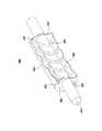
図2は、流体供給装置220、及びガス輸送導管210の周りに形成された熱交換器230が組み込まれた冷却装置200を示している。熱交換器230は、キャップ231、233を備え、外側の導管232は、これらの間に配設されている。流体供給装置220は、ポンプによって、アウトレット225から流体を流出し、インレット224に流体を流入させる。 FIG. 2 shows a
この図に示すように、キャップ231は、インレット237及び圧力逃し弁235を備える。インレット237は、外側の導管232の内部に配設されたチューブ構造(図3〜図4に関して後述する)と流体連通し(fluidly communicate)、流体が熱交換器230に入ることを可能にしている。更に、キャップ233は、アウトレット236を有し、流体は、ここから、熱交換器230を出る。他の実施の形態として、インレットとアウトレットとを逆にしてもよい。 As shown in this figure, the
流体供給装置220は、ポンプによって、そのアウトレット225から、流体管路223を介して、インレット237に流体を流す。流体は、インレット237から熱交換器230内のチューブ構造を流れる。熱交換器230内では、流体が加熱された後、アウトレット236から流出する。アウトレット236から流出した流体は、流体管路222を介して、流体供給装置220のインレット224に流れる。インレット224に入る流体は、好ましくは、アウトレット225からポンプで送られた流体より高温であるので、流体供給装置220は、好ましくは、例えば、冷凍又は他の冷却装置を用いて、受け入れた流体を冷却するように構成されている。流体は、加熱されると急速に膨張するので、圧力逃し弁235を設け、圧力が所定の閾値を超えている期間、流体を排出することによって、熱交換器230内から圧力を解放する。また、圧力逃し弁は、外側の導管の壁を介して取り付けてもよい。 The
図3は、例示的な熱交換器300を示している。熱交換器300は、キャップ320、330によってガス輸送導管310に密封された外側の導管340を備える。ガス輸送導管310及び外側の導管340は、これらの間に、環状チャンバ(toroidal chamber)360を形成する。環状チャンバ360内では、熱伝導管構造350が、上述したような流体供給装置に流体的に接続されており、これによって、流体は、流体供給装置から、熱伝導管構造350を介して、外側の導管340に入り、及びここから出て、流体供給装置に戻ることができる。熱伝導管構造350は、好ましくは、環状チャンバ360の環状形状を形成するために、曲がっている。更に、環状チャンバ360内の熱伝導管構造350によって形成される残りの空間は、静的流体によって満たされている。 FIG. 3 shows an
流体は、熱交換器300内で、インレット325からアウトレット335まで熱伝導管構造350を流れる。流体が熱伝導管構造350を流れると、流体は、熱伝導管構造350に密接に接触し、熱伝導管構造は、環状チャンバ360内の静的流体に密接に接触し、この静的流体は、ガス輸送導管310にも密接に接触している。動作時には、高温の気体がガス輸送導管310を流れ、ガス輸送導管310を加熱する。熱は、ガス輸送導管310から環状チャンバ360内の静的流体を介して、熱熱伝導管構造350に、そして、ここを流れる流体に伝導される。流体がインレット325からアウトレット335に流れる際に、熱熱伝導管構造350から流体に熱が伝導され、この結果、流体が加熱される。加熱された流体がアウトレット335から流れ、流体供給装置に戻ると、熱交換器から熱が除去され、これによって、ガス輸送導管310から熱が除去され、これによって、ガス輸送導管310が動作温度に維持される。 The fluid flows through the heat
図4は、熱交換器400を示している。熱交換器400は、キャップ420、430によってガス輸送導管410に密封された外側の導管440を備える。ガス輸送導管410及び外側の導管440は、これらの間に、環状チャンバ460を形成する。環状チャンバ460内では、熱伝導管構造450が、上述したような流体供給装置に流体的に接続されており、これによって、流体は、流体供給装置から、熱伝導管構造450を介して、外側の導管440に入り、及びここから出て、流体供給装置に戻ることができる。熱伝導管構造450は、ガス輸送導管410の周りに、好ましくは、螺旋状に巻回され、これによって、環状チャンバ460の環状形状を形成している。更に、環状チャンバ460内の熱伝導管構造450によって形成される残りの空間は、静的流体によって満たされている。 FIG. 4 shows a
流体は、熱交換器400内で、インレット425からアウトレット435まで、熱伝導管構造450を流れる。流体が熱伝導管構造450を流れると、流体は、熱伝導管構造450に密接に接触し、熱伝導管構造は、環状チャンバ460内の静的流体に密接に接触し、この静的流体は、ガス輸送導管410にも密接に接触している。動作時には、高温の気体がガス輸送導管410を流れ、ガス輸送導管410を加熱する。熱は、ガス輸送導管410から環状チャンバ460内の静的流体を介して、熱熱伝導管構造450に、そして、ここを流れる流体に伝導される。流体がインレット425からアウトレット435に流れる際に、熱熱伝導管構造450から流体に熱が伝導され、この結果、流体が加熱される。加熱された流体がアウトレット435から流れ、流体供給装置に戻ると、熱交換器から熱が除去され、これによって、ガス輸送導管410から除去され、これによって、ガス輸送導管410が動作温度に維持される。 The fluid flows through the heat
図5は、本発明の原理に基づいて流体混合物を冷却する方法500の一実施の形態を示すフローチャートである。当業者にとって明らかなように、ここに、説明するプロトコル、処理及び手順は、必要に応じて、継続的に繰り返してもよく、何回繰り返してもよい。更に、ここでは、方法500の各ステップを特定の順序で示しているが、幾つかの一定のステップを同時に実行してもよく、図に示すものとは異なる順序で実行してもよい。したがって、本発明の処理ステップは、特許請求の範囲において、明示的又は暗示的に指定している場合を除き、如何なる特定の順序にも限定されない。 FIG. 5 is a flowchart illustrating one embodiment of a
ステップ510では、熱交換器(heat exchanger)に流体的に接続された流体供給装置(fluid supply system)を備える冷却装置(cooling system)を準備する。熱交換器は、外側の導管(outer conduit)と、熱伝導管(conductive tube)とを備える。外側の導管は、ガス輸送導管(gas transport conduit)の周りに配置され、第1の端部と、第1の端部の反対側の第2の端部と、第1の端部を覆う第1のキャップと、第2の端部を覆う第2のキャップとを備える。ガス輸送導管は、第1のキャップを介して外側の導管内に入り、第2のキャップを介して外側の導管から出ている。これに関連して、熱伝導管は、外側の導管を通過する。なお、熱伝導管は、外側の導管を通過するために、第1のキャップ及び第2のキャップを除く熱交換器の一部を通過してもよい。静的流体チャンバ(static fluid chamber)は、熱伝導管とガス輸送導管の間で形成され、静的流体(static fluid)を収容する。 In
ステップ520において、粒子混合気体生成装置(mixture production system)は、流体混合物を生成する。粒子混合気体生成装置は、ガス輸送導管に流体的に接続されている。流体混合物は、様々な手法で生成できる。なお、好ましい実施の形態では、粒子混合気体生成装置は、処理ガスを励起し、プラズマ流(plasma stream)を形成し、プラズマ流を粉末粒子に印加して、粉末粒子を蒸発させ、蒸発した粒子を含む流体混合物を形成する。 In
ステップ530において、流体混合物がガス輸送導管を流れ、熱交換器の外側に入り、ここから出る。 In
ステップ540において、循環流体が熱伝導管を流れ、熱交換器の外側の導管に入り、ここから出る。なお、このステップは、流体混合物が熱交換器を流れるステップ530と同時に行ってもよい。 In
ステップ550において、ガス輸送導管が、ガス輸送導管内の流体混合物から静的流体チャンバ内の静的流体に熱を伝導する。 In
ステップ560において、熱伝導管が、静的流体チャンバ内の静的流体から熱伝導管を流れる循環流体に熱を伝導する。 In
ステップ570において、加熱循環流体が熱交換器から流れる。好ましい実施の形態では、循環流体は、流体供給装置に戻って、好ましくは、冷却された後、熱交換器に再循環され、プロセスが繰り返えされる。 In
本発明の構造及び動作の原理を明瞭にするために、詳細を組み込んだ特定の実施の形態に関連して本発明を説明した。したがって、ここにおける特定の実施の形態及び詳細な説明は、特許請求の範囲を限定するものではない。本発明の精神及び範囲から逸脱することなく、ここに例示した実施の形態を変更できることは当業者にとって明らかである。 In order to clarify the principles of structure and operation of the present invention, the invention has been described with reference to specific embodiments incorporating details. Accordingly, the specific embodiments and detailed description herein are not intended to limit the scope of the claims. It will be apparent to those skilled in the art that the illustrated embodiments can be modified without departing from the spirit and scope of the invention.
本出願は、2005年4月19日に出願され、係属中の米国特許出願番号第11/110,341号、発明の名称「HIGH THROUGHPUT DISCOVERY OF MATERIALS THROUGH VAPOR PHASE SYNTHESIS」及び2007年5月11日に出願され、係属中の米国仮特許出願番号第60/928,946号、発明の名称「MATERIAL PRODUCTION SYSTEM AND METHOD」の優先権を主張し、これらは何れも、引用することによって、本願に援用される。This application was filed on April 19, 2005, pending US patent application Ser. No. 11 / 110,341, entitled “HIGH THROUGHPUT DISCOVERY OF MATERIALS THROUGH VAPOR PHASE SYNTHESIS” and May 11, 2007.filed U.S. provisional Patent application No. 60 / 928,946 pending claims priority entitled "MATERIAL PRODUCTION SYSTEM aND METHOD" of the invention, both of which, by reference, incorporated herein Is done.
本発明は、高温気体又は混合気体(gaseous mixtures)を流す気体輸送導管を冷却する方法及びシステムに関する。The present invention relates to a method and system for cooling theto gas transport conduit flow a hot gas or gas mixture (gaseous mixtures).
気相粒子生成反応器(gas phase particle production reactor)では、基本的な生成種(basic product species)は、エネルギ供給ゾーン(energy delivery zone)から高温の反応物質を噴出した後の非常に短い時間に形成される。粒子種は、急速に形成されるが、汚染されることなく、所望の粒子特性を達成するために、気体粒子生成物(gas-particle product)の冷却は、慎重に調整しなければならない。多くの場合、この慎重に調整された冷却は、システム内の回収点に気体粒子生成物(gas-particle product)を配送する気体輸送装置内で行われる。In a gas phase particle production reactor, the basic product speciesis released in a very short time after ejecting hot reactants from the energy delivery zone. It is formed. The particle species are formed rapidly, but the cooling of the gas-particle product must be carefullyadjusted in order to achieve the desired particle properties without being contaminated. In many cases, this carefullytuned cooling is done ina gas transport device that deliversa gas-particle product to a collection point in the system.
高温の気体粒子生成物は、大きな熱量を含み、これを放出するので、気相粒子生成反応器から気体粒子生成物を導くのに適した気体輸送装置は、高い熱負荷を効率的に吸収し、放散するように設計しなければならない。2つの系間の熱伝導は、2つの系間の温度差に比例して起こるので、気体粒子生成物(gas-particle product)からの効率的な熱吸収は、気体輸送装置を気体粒子生成物よりも大幅に低い温度に維持することによって決まり、一方、気体輸送装置からの効率的な熱放散は、気体輸送装置に接触する周囲を更に低い温度に維持することによって決まる。吸収及び放散の個々の要件は、相容れないものである。気体輸送装置は、通常、その温度を高めずには、大きな熱量を吸収できない。多くの場合、2つの要件は、気体輸送装置を能動的に冷却することによって、バランスがとれ、これにより、気体輸送装置が熱を放散できるように調整された低温環境が提供される。Gaseous particles products of high temperature, comprises alarge heatquantity will release thisgas transportapparatus suitable from the gas phase particle production reactorto direct gaseous particlesproduct efficiently absorb high thermal loads And must be designed to dissipate. The heatconductionbetween the two systems, since occurs in proportion to the temperature differencebetween the two systems, efficientheat absorption from the gas particles product (gas-particle product), the gaseous particles the productgas transport devicedetermined by the maintaining the temperaturesignificantly lowerthanthe other hand, efficientheat dissipation from thegas transport device isthus determined to maintainthe ambient in contact with thegas transport deviceto a lower temperature. The individual requirements for absorption and release are incompatible.Gas transport system, usually do not increase its temperature, it can not absorb thelarge amount of heat. Often, the two requirements, by actively cooling thegas transport device, balanced, thereby,the gas transport device is adjusted low-temperature environment is provided to allow dissipate heat.
従来の技術における気体輸送装置の最も一般的な能動的冷却方式は、強制流体冷却(forced fluid cooling)を含む。従来の気体輸送冷却器では、強制気体冷却装置(forced-gas cooling system)及び液体冷却装置(liquid cooling system)を含む様々な強制流体冷却装置が使用されている。The most common active cooling scheme forgas transport devices in the prior art involves forced fluid cooling. In a conventionalgas transport cooler, forcedair cooling system (forced-gas cooling system) and various forced fluid cooling system comprisinga liquid cooling device (liquid cooling system) is used.
強制気体冷却装置は、通常、1つ以上のファンを備え、ファンは、気体輸送装置に熱的に接続された1つ以上の熱交換機構に気体を強制的に流す。熱は、気体粒子生成物(gas-particle product)から気体輸送装置に移動し、そして、熱交換機構に移動する。通常、熱交換機構は、熱交換領域内の気体に対する大表面積の界面を提示する除熱器又はヒートシンクを備える。気体が、熱交換領域を通して、大表面積の除熱器又はヒートシンクに亘って移動すると、気体は、除熱器又はヒートシンクを対流的に冷却する。このような装置は、動作が簡単で比較的安価であるが、気体の熱容量は、一般的に、液体の熱容量よりも小さく、気体は、殆ど対流的手段によって冷却し、気体は、液体程速く冷却することができないので、液体冷却装置よりも効率が低い。したがって、強制気体冷却装置は、熱負荷が高い粒子混合気体(gas-particle mixture)を冷却するためには、適していない。Forcedgas cooling system is usuallyprovided with one or more fans, the fan forces the flowto the gas to one or more heat exchangemechanismthat is thermally connected to thegas transport system. Heat is transferred from the gas-particle product to thegas transport device and then to the heat exchangemechanism . Typically, the heat exchangemechanism comprises a heat remover or heat sink thatpresents ahigh surface areainterface to the gas in the heat exchange region. Gas,through the heat exchange area, movingacross the heat rejector or heat sinkof the large surface area, the gas, the heat rejector or sink convectively cooled. Suchdevices aresimple to operate and relatively inexpensive, but the heat capacity of gas is generally less thanthat of liquid, the gas is cooled almost by convectivemeans ,and the gas is as fast as the liquid. Since it cannotbe cooled, itis less efficientthan aliquid cooling device. Therefore, the forcedgas cooling device is not suitable for cooling a gas-particle mixture having a high heat load.
液体冷却装置は、通常、液体循環装置を備え、液体循環装置は、気体輸送装置に熱的に接続された1つ以上の熱交換機構に流体を流す。熱交換機構は、強制気体冷却装置と同様に、通常、熱交換領域内の液体と相互作用する大表面積を提示する。熱は、気体輸送装置に吸収され、熱交換機構に伝導される。液体が熱交換表面に沿って移動すると、熱は、熱交換機構から、伝導及び対流的手段によって、液体内に放散され、加熱された液体は、熱交換領域から流れ出る。熱は、通常、加熱された液体から、更なる冷却又は冷房機構によって除去される。Liquid cooling system typicallyincludes a liquid circulation device, the liquid circulating apparatusto flow the fluid into one or more heat exchangemechanismthat is thermally connected to thegas transport system. The heat exchangemechanism , like the forcedgas cooling device, typicallypresents alarge surface areathat interacts with the liquid in the heat exchange region. Heat is absorbed by thegas transport device and conductedto the heat exchangemechanism . As liquid moves along the heat exchangetable surface, heat from the heat exchangesystem,by conduction and convectionmeans, aredissipated intothe fluid, the heated fluid flows out of the heat exchange area. Heat, usually from the heated liquidis removedby further cooling orcooling mechanism.
効率的に冷却する場合、熱交換領域の全容積に対して、新たな、冷たい液体を絶えず供給する必要がある。大容積の熱交換領域を有する装置では、効率的に動作させるためには、大容量の冷却液が必要であり、結果として、運用コストが高くなる。小容積の熱交換領域も知られているが、その製造方法は、困難で、高価であり、結果して、組立費用が高くなる。更に、小容積の熱交換領域を有する多くの装置は、異物に対して非常に敏感であり、したがって、高価な予防措置、例えばフィルタと、順調に働かせるための定期的な保守とが必要となる。If cooledefficiently,for the total volume of the heat exchange area,the new, it is necessary toconstantly supply the cold liquid. In thedevice having a heat exchange regionof thelarge-volume,in order to operate efficiently, itis necessary coolantmass.As a result, operational costs are high. Are also known heat exchange areaofsmall volume, and itsmethod of manufacture, difficult, expensive,and result,assembling costs is high. In addition, manydeviceswith asmall volumeheat exchange area are very sensitive toforeign objects ,thusrequiring expensive precautions such as filtersand regularmaintenanceto work smoothly. .
気体輸送装置を冷却する現在の方法は、高熱負荷装置を取り扱うためには十分に効率的でない強制気体冷却装置と、製造及び維持が高価な液体冷却装置との何れかに頼っている。Currentmethods for cooling thegas transport system,a forcedgas coolingsystemis notefficient enoughto handletakehigh heat loaddevice,manufacture and maintain rely on eitheran expensiveliquid cooling apparatus.
本発明は、導管用の冷却装置を提供する。例示的な側面においては、本発明に基づく冷却装置は、混合気体(gas mixture)を輸送する導管を冷却するために使用される。冷却装置は、主に、導管が輸送する気体粒子生成物から導管が吸収した熱を放散することを意図する。例示的なシステムでは、気相粒子生成反応器(gas phase particle production reactor)、例えば噴射型反応器(flame reactors)、プラズマ反応器、熱壁反応器(hot wall reactor)、レーザ反応器のから、高温の気体粒子生成物が放出される。導管は、反応器から排出された蒸気混合気体(gas-vapor mixtures)を輸送及び調整し、複数の手段によって、混合物から熱を吸収する。冷却装置は、導管内で吸収された熱を放散し、導管の過熱を防止するように機能する。The present invention provides a cooling device for a conduit. In an exemplary aspect, the cooling device according to the present invention is used to cool a conduit carrying a gas mixture. The cooling device is primarily intended to dissipate the heat absorbed by the conduit from the gaseous particle product transported by the conduit. Exemplary systems include gas phase particle production reactors, such as, for example, flame reactors, plasma reactors, hot wall reactors, laser reactors, A hot gaseous particle product is released. The conduit transports and regulates the gas-vapor mixture discharged from the reactor and absorbs heat from the mixtureby a plurality of means. The cooling device functions to dissipate heat absorbed in the conduit and prevent overheating of the conduit.
本発明は、導管装置内の気体輸送導管の選択された部分を冷却する冷却装置を提供する。好ましくは、冷却装置は、第1の端部及び第2の端部を有する外側導管の部分を含む気体輸送導管の一部を冷却する少なくとも1つの冷却要素を備える。冷却要素は、気体輸送導管の一部の周りに巻回され、外側導管の内面(interior surface)と気体輸送導管の外面の間に環状チャンネルを形成する。外側導管と気体輸送導管間に形成された環状チャンネルは、導管の第1の端部における第1の開口と、導管の第2の端部における第2の開口とを有する。外側導管内には、高熱伝導管構造体(highly heat conductive tube structure)が配置され、環状チャンネルを形成する。更に、高熱伝導管構造体は、好ましくは、チャンネルを密封せず、如何なる点においても流体が流れるようにし、高熱伝導管構造体を適切に配置することによって、流体は、環状チャンネル内を自由に動くことができる。なお、他の実施の形態では、冷却装置は、環状チャンネル内に仕切りを設け、高熱伝導管構造体を流れる流体を除いて、環状チャンネルを密封する。この側面では、環状チャンネルは、複数のチャンバに分割され、これらのチャンバのそれぞれは、異なる流体を収容し、高熱伝導管構造体は、複数のチャンバのそれぞれを通過する。The present invention provides a cooling device for cooling selected portions of agas transport conduit within a conduit device. Preferably, the cooling device comprises at least one cooling element that coolsa portion of thegas transport conduit including a portion of the outerconduit having a first end and a second end. Cooling element is wound around a portion of thegas transport conduit to form an annular channel between the inner surface of the outerconduit (interior Surface) of the outer surface of thegas transport conduit. An annular channel formedbetween the outerconduit and thegas transport conduit has a first opening at the first end of the conduit and a second opening at the second end of the conduit. In the outerconduit,the high thermal conductive tubestructure (highly heat conductive tube structure) isplaced to form an annular channel. Furthermore,high thermal conductivity tubestructure preferably does not seal the channel, to flow fluid in any way, by properlyplace thehigh heat conductive tubestructure, fluid freely in the annular channel Can move on. In other embodiments, the cooling device, a partition is provided in the annular channel, with the exception of the fluid flowing through thehigh thermal conductive pipestructure to seal the annular channel. In this aspect, the annular channel is divided into a plurality of chambers, each of the chambers, to accommodate different fluid,high thermal conductivity tubestructure passes through each of the plurality of chambers.
環状チャンネルに導入された高熱伝導管構造体と共に、環状チャンネルの第1の開口に取り付けられた第1のキャップ及び第2の開口に取り付けられた第2のキャップは、気体輸送導管と導管との間を密封する。環状チャンネルは、高熱伝導管構造体を囲み、これと熱接触する静的流体(static fluid)、好ましくは、液体で満たされる。キャップのうちの少なくとも1つは、高熱伝導管構造体への流体輸送を実現するためのポートを有する。流体タンクシステムは、1つ以上のポートに接続され、これによって、高熱伝導管構造体に接続されている。好ましい実施の形態では、キャップ及び外側導管がモジュールとして形成され、互いに密封されるが、他の実施の形態では、キャップ及び外側導管を一体に形成してもよい。Withhigh thermal conductivity tubestructure introduced into the annular channel, a second cap attached to the first cap and a second opening which is attached to the first opening of the annular channel,gas transport conduit and the conduitand the Seal the gap. Annular channel surrounds thehigh thermal conductive tubestructure, which in thermal contact with the static fluid (Static fluid), preferably filled with liquid. At least one of the cap has a port for realizing fluid transport intohigh thermal conductivity tubestructure. Fluid tank system is connected to one or more ports, thereby, is connected to thehigh heat conductive tubestructure. In the preferred embodiment, the cap and outerconduit are formed as a module and sealed together, but in other embodiments, the cap and outerconduit may be integrally formed.
このように、本発明の実施の形態のそれぞれは、互いに独立した2つの流体システム、すなわち、循環システム(circulating system、「流体(fluid)」又は「循環流体(circulating fluid)」と呼ぶ)及び静的システム(static system、「静的流体(static fluid)」と呼ぶ)を含む。各システム内で使用するために選択される流体は、それぞれの実施の形態の詳細によって異なる好ましい特性を有する。 Thus, each of the embodiments of the present invention includes two fluid systems that are independent of each other: a circulating system (referred to as a “fluid” or “circulating fluid”) and a static system. Including a static system (referred to as a "static fluid"). The fluid selected for use in each system has favorable characteristics that vary depending on the details of each embodiment.
導管装置は、高温の気体が流され、この気体から熱を吸収する。気体は、導管装置内を移動しながら冷却されるので、導管装置の幾つかの部分は、他の部分よりも多くの熱を吸収する。導管装置内の気体輸送導管の例示的な部分は、先の段落で説明した冷却装置を備える。The conduit device is flushed with hot gas and absorbs heat from this gas. As the gas cools as it travels through the conduit device, some parts of the conduit device absorb more heat than others. An exemplary portion of agas transport conduit within a conduit device comprises the cooling device described in the previous paragraph.
本発明の冷却装置は、流体の流れによって、気体輸送導管から熱を除去することによって動作する。導管内の気体から気体輸送導管に熱が吸収されると、冷却装置は、導管の外側表面を介して導管から熱を除去する。熱は、導管装置から静的流体に移動し、静的流体を加熱する。静的流体は、高熱伝導管構造体に熱接触しており、熱を高熱伝導管構造体に伝導する。流体は、流体タンクシステムから高熱伝導管構造体に流れ、高熱伝導管構造体及び静的流体を介して、導管装置から熱を吸収する。流体は、高熱伝導管構造体から流体タンクシステム又は他の流体タンク(fluid reservoir)に流れる。当業者には明らかなように、(流体が同じタンクシステムに戻る)循環システムでは、冷却効率を維持するために、流体は、好ましくは、外部の手段、例えば冷房によって冷却された後、高熱伝導管構造体に供給される。The cooling device of the present invention operates by removing heat from thegas transport conduit by the flow of fluid. As heat is absorbed from thegas in the conduit into thegas transport conduit, the cooling device removes heat from the conduit through the outer surface of the conduit. Heat is transferred from the conduit device to the static fluid and heats the static fluid. Static fluid is in thermal contact with thehigh heat conductive tubestructure, conductsheat to thehigh thermal conductivity tubestructure. Fluid flows from the fluid tank system tohigh heat conductive tubestructure, via thehigh thermal conductivity tubestructure and static fluid absorbs heat from the conduit system. Fluid flows into the fluid tank system or other fluid tanks fromhigh heat conductive tubestructure (fluid reservoir). As will be apparent to those skilled in the art, in a circulation system (where the fluid returns to the same tank system), in order to maintain cooling efficiency, the fluid preferably has ahigh thermal conductivity after being cooled byexternal means such as cooling . It is supplied to thetubestructure.
機能的には、冷却装置内の各冷却セルは、熱交換領域、流体フロー制御及び供給システム等の幾つかの部品を備える。これらの部品が連携して動作することによって、セルは、導管装置の特定の領域を有効に冷却する。このような連携して動作する複数のセルを有する冷却装置は、選択的で、拡張可能で、構成可能な冷却を導管装置に提供する。本発明は、システム内のセルの各部品について、所望の構造及び機能を含む。 Functionally, each cooling cell in the cooling device comprises several components such as a heat exchange zone, fluid flow control and supply system. These components work together to effectively cool a particular area of the conduit device. Such a cooling device having a plurality of cells operating in concert provides selective, expandable and configurable cooling to the conduit device. The present invention includes the desired structure and function for each part of the cells in the system.
本発明には、幾つかの熱交換領域がある。組み立てられたシステムでは、高熱伝導管構造体は、気体輸送導管と外側導管間で画定され、静的流体で満たされている環状チャンネル内に配置されている。高熱伝導管構造体は、好ましくは、環状チャンバ内で、導管に沿って螺旋状に巻回されている。環状チャンネル内の導管と静的流体の界面の領域は、第1の熱交換領域を形成し、熱は、気体輸送導管から静的流体に伝導される。環状チャンネル内の静的流体と高熱伝導管構造体の界面は、第2の熱交換領域を形成し、熱は、静的流体から高熱伝導管構造体に伝導される。高熱伝導管構造体の内面は、第3の熱交換領域を形成し、熱は、高熱伝導管構造体から循環流体に伝導される。There are several heat exchange zones in the present invention. In the assembled system,high thermal conductivity tubestructure isdefinedbetweenthe gas transport conduit and outerconduit areplaced in an annular channel which is filled with a static fluid.High thermal conductivity tubestructure is preferably in the annular chamber, they are wound helically along the conduit. The region of the interface between the conduit and the static fluid in the annular channel forms a first heat exchange region, and heat is conducted from thegas transport conduit to the static fluid. Interface static fluid and thehigh thermal conductive tubestructure within the annular channel, the second heat exchange zone is formed, heat is conducted to thehigh thermal conductivity tubestructure from a static fluid. The inner surface of thehigh thermal conductive pipestructure, the third heat exchange region is formed, heat is transferred to the circulating fluid from thehigh heat conductive tubestructure.
高熱伝導管構造体は、好ましくは、熱良導体を曲げて形成される。好ましい材料には、銅等の金属及び熱良導性熱可塑性樹脂等が含まれる。上述のように、高熱伝導管構造体は、その内部に流体を流すことができる。本発明では、流体の流れを可能にするために様々な構造を考慮する。様々な実施の形態では、高熱伝導管構造体は、多孔質構造体及び/又は流体流路を定義するチャンネル構造体を含む。高熱伝導管構造体は、高熱伝導管構造体の容積に対して、熱交換のための広い表面積を有することが好ましい。High thermal conductivity tubestructure is preferably formed by bending a good thermal conductor. Preferred materials include metals such as copper and thermally conductive thermoplastic resins. As mentioned above,high thermal conductivity tubestructure can be made to flow fluid therein. The present invention contemplates various structures to allow fluid flow. In various embodiments,the high thermal conductive tubestructure comprises a channelstructure defining the porousstructure and / or fluid flow path.High thermal conductivity tubestructure, relative to the volume of thehigh heat conductive tubestructure, it is preferable to have a large surface area for heat exchange.
高熱伝導管構造体は、好ましくは、コイルバネの形状と同様に、螺旋状に巻回され、環状チャンネル内で気体輸送導管を周回する環状形状を形成する。本発明は、環状チャンネル内の高熱伝導管構造体の様々な構成を考慮し、これらには、コイル状構成、折り重ね構成、多層化構成等が含まれる。高熱伝導管構造体は、導管から独立して形成してもよく、導管の周りに形成してもよい。形成の手法に拘わらず、高熱伝導管構造体は、環状チャンネル内に適合する。High thermal conductivity tubestructure is preferably similar to the shape of the coil spring is wound spirally to form an annular shape around thegas transport conduit in the annular channel. The present invention takes into account the various configurations of thehigh heat conductive tubestructure within the annular channel, these include coiled configuration, folded configuration, includes multi-layered structure and the like.High thermal conductivity tubestructure may be formed independently from the conduit may be formed around the conduit. Regardless of the formation technique,the high thermal conductive pipestructure, it fits into the annularchannel.
例示的な実施の形態では、気体輸送導管に巻回された銅管が、高熱伝導管構造体を形成する。銅管は、好ましくは、粗く巻回され、物理的に気体輸送導管に接触してもよいが、接触していなくてもよい。高熱伝導管構造体を囲む外側導管を設けることによって、高熱伝導管構造体を含む環状チャンネルが形成される。環状チャンネルは、密封され、静的流体で満たされる。静的流体の充填は、外側導管の片端の密封後、他端の密封前に行ってもよい。これに代えて、充填は、熱交換器の一方又は両方の端部に設けられた弁装置によって行ってもよい。In an exemplary embodiment, the copper tube wound ina gas transportation conduit, to form ahigh heat conductive tubestructure. The copper tube is preferably coiled roughly and may or may not physically contact thegas transport conduit. By providing the outerconduit surrounding thehigh heat conductive tubestructure, an annular channel including ahigh thermal conductivity tubestructure is formed. The annular channel is sealed and filled with static fluid. The static fluid filling may be performed after sealing one end of the outerconduit and before sealing the other end. Alternatively, the filling may be performedby a valve device provided in one or both ends of the heat exchanger.
流速制御装置は、幾つかの機能を有する。流体冷却装置内の放熱の速度は、多くの要素に依存し、これらのうちの幾つかは、システム内の流体の速度及び種類に関連する。有効な流速制御装置は、熱交換領域の所望の部分に流体を流通させる手段を備える。また流体は、加熱によって膨張し、及び流体冷却装置内の放熱は、流体の加熱に依存するので、流体制御装置は、流体内の圧力変化を考慮する必要がある。同様に、外側導管内に形成される環状チャンバ及び2つのシールは、好ましくは、流体内の圧力変化を調整する弁装置を備える。The flow rate control device has several functions. The rate ofheat release in the fluid cooling device depends on many factors, some of which are related to the speed and type of fluid in the system. An effective flow rate control device comprises means for flowing fluid through a desired portion of the heat exchange area. Also, the fluid expands due to heating, and theheat dissipation in the fluid cooling device depends on the heating of the fluid, so the fluid control device needs to take into account the pressure change in the fluid. Similarly, the annular chamber and the two seals formed in the outerconduit preferably comprisea valve device that regulates pressure changes in the fluid.
本発明は、幾つかの部分を有する流体制御装置を提供する。外側導管は、内部に静的流体が満たされる環状チャンバを形成する閉込め構造を提供する。したがって、導管は、高熱伝導管構造体内の流路を除く環状チャンバ内の流体の総体積を画定する。更に、外側導管の端部を密封する各キャップは、好ましくは、複数のポートを有している。これらのポートは、流体が高熱伝導管構造体に流れるパターンを決定し、この結果、高熱伝導管構造体内のフロー構造と共に、高熱伝導管構造体を介する流れのパターンを決定する。更に、キャップ構造体は、突然の圧力上昇が発生した場合、システムから流体を排出する1つ以上の圧力逃し弁を備えることが好ましい。更に、流体制御装置は、シーリングキャップの1つに設けられた複数のポートを介して流体を提供するポンプを有していてもよい。The present invention provides a fluid control device having several parts. The outerconduit provides a confinement structure that forms an annular chamber that is filled with static fluid. Thus, the conduit defines a total volume of fluid in the annular chamber except the flow path in thehigh heat conductive tubestructure. Further, each cap that seals the end of the outerconduit preferably has a plurality of ports. These ports, determines the pattern of fluid flows inhigh heat conductive tubestructure, as a result, the flow structure within thehigh heat conductive tubestructure, to determine the pattern of flow through thehigh thermal conductivity tubestructure. Furthermore, the capstructure, if they occur a sudden pressure rise is preferably provided with one or more pressure relief valvefor discharging the fluid from the system. Further, the fluid control device may havea pump that provides fluid through a plurality of ports provided in one of the sealing caps.
外側導管は、好ましくは、高熱伝導管構造体と共に、環状領域内の所定の流体容積を定義する。ある実施の形態の比容積及び流速は、その実施の形態において設計されている熱負荷に依存する。概略的に言えば、より高い熱負荷を扱うためには、より大きい容積及び流速が必要である。また、必要な流体容積を決定する際には、伝導率及び表面積も検討される。Outerconduit, preferably, together with thehigh heat conductive tubestructure defining a predetermined fluid volume in the annularregion. The specific volume and flow rate of an embodiment depends on the heat load designed in that embodiment. In general, larger volumes and flow rates are required to handle higher heat loads. Also, conductivity and surface area are considered when determining the required fluid volume.
外側導管は、好ましくは、耐久性及び耐熱性を有する材料から形成される。外側導管を形成する材料は、熱伝導性を有する必要はない。実際に、外側導管を介する放熱を最小にするためには、少なくとも外面は、断熱材から形成することが好ましい。この構成は、放熱及び冷却装置の構造機能を分離する。これに代えて、外面は、熱伝導性であってもよく、この場合、放射によって更なる熱損失が促進される。The outerconduit is preferably formed from a material that is durable and heat resistant. The material forming the outerconduit need not be thermally conductive. In fact, in order to minimizeheat dissipation through the outerconduit , at least the outer surface is preferably formed from a thermal insulator. This configuration separates the structural functions of theheat dissipation and cooling devices. Alternatively, the outer surface may be a thermally conductive, in this case, additional heatloss is facilitatedby the radiation.
キャップは、外側導管の端部に取り付けられ、これを密封する。様々な実施の形態において、キャップは、外側導管に接着され、螺着され、又はボルト付けされる。本発明は、キャップと外側導管間にシールを形成する如何なる結合も包含する。キャップは、好ましくは、外側導管と同様の材料から形成される。更に、導管装置とキャップの間のシールは、様々な方法で形成することができ、キャップは、接着してもよく、圧着してもよく、Oリングタイプのシールによって適切な位置に保持してもよい。キャップを密封する好ましい手法は、熱交換器が加熱及び冷却される際のキャップの伸縮に応じて決定される。A cap is attached to the end of the outerconduit and seals it. In various embodiments, the cap is glued, screwed or bolted to the outerconduit . The present invention encompasses any bond that forms a sealbetween the cap and the outerconduit . The cap is preferably formed from the same material as the outerconduit . In addition, the seal between the conduit device and the cap canbe formed ina variety ofways , the cap may be glued, crimped, and held in place by an O-ring type seal. Also good. The preferred approach for sealing the cap is determined by the expansion and contraction of the cap as the heat exchanger is heated and cooled.
更に、キャップは、それぞれ、好ましくは、複数のポートを有する。上述のように、ポートの1つは、好ましくは、外側導管の各端部において、流体システムのための圧力逃しシステムを提供する。他のポートは、特定の構成において、流体輸送を高熱伝導管構造体に提供する。ポートの構成及び高熱伝導管構造体内の流体チャンネルの構成は、互いに補い合って、システムを介する所望の流路を形成する。流路の構成及び流路への流体輸送の速度は、気体輸送導管から流体への放熱の速度を部分的に決定する。Furthermore, each cap preferably has a plurality of ports. As described above, one of the ports preferably provides a pressure relief system for the fluid system at each end of the outerconduit . Other ports, in certain configurations, providing fluid transport inhigh heat conductive tubestructure. Configuration of the fluid channel in the port structure andhigh heat conductive tubestructure is complemented each other, to form a desired flow path through the system. The configuration of the channel and the rate of fluid transport to the channel partially determine the rate ofheat dissipation from thegas transport conduit to the fluid.
流体制御装置は、更に、流体ポンプと、流体供給装置とを備えていてもよく、これらは、単一の装置として統合することが合理的であるが、モジュール的に実現してもよい。流体ポンプは、複数のポートへの流体輸送の速度を決定し、この結果、高熱伝導管構造体を流れる流体の速度を決定する。流体の流速が速い程、システムは、より多くの量の熱を放散できる。したがって、流体の流速は、放熱の必要条件の変化に応じて変更することが好ましい。The fluid control device may further comprise a fluid pump and a fluid supply device, which are reasonable to integrate as a single device, but may be implemented in a modular manner. Fluid pump determines the rate of fluid transport into a plurality of ports, the result, determines the speed of the fluid flowing through thehigh thermal conductivity tubestructure. The faster the fluid flow rate, the more heat can be dissipated by the system. Therefore, it is preferable to change the flow rate of the fluid in accordance with changes inthe necessary heat dissipation conditions .
本発明の冷却装置を組み込む気体生産システム内の熱生成は、必ずしも一定ではないため、本発明の冷却装置は、好ましくは、放熱のための要求の変化に対応するために、流体の流速を変更できる。本発明の一側面においては、制御装置は、熱交換領域に流れる流体と熱交換領域から流れる流体の間で測定された温度差に基づいて、ポンプ及び流体供給装置を制御する。温度差が指定の限界を超えた場合、最大流速を超えない限り、流速が高められる。Since heat generation within a gas production system incorporating the cooling device of the present invention is not necessarily constant, the cooling device of the present invention preferably changes the fluid flow rate to accommodate changing demands forheat dissipation. it can. In one aspect of the present invention, the control device controls the pump and the fluid supply device based on a temperature difference measured between the fluid flowing in the heat exchange region and the fluid flowing from the heat exchange region. If the temperature difference exceeds the specified limit, the flow rate will be increased unless the maximum flow rate is exceeded.
流体供給装置は、好ましくは、冷却流体を流体ポンプに供給する。この流体は、新しいもの、すなわち以前にシステムで使用されていない流体であってもよく、或いは、流体は、再循環してもよい。流体を再循環する場合、流体供給装置は、好ましくは、再循環された流体を冷却した後、ポンプに再供給する。流体供給装置には、圧力逃し弁を組み込むことができる。本発明では、幾つかの種類の流体が考慮される。好ましい流体は、高い熱伝導率を有する。The fluid supply device preferably supplies cooling fluid to the fluid pump. This fluid may benew , ie a fluid that has not been previously used in the system, or the fluid may be recirculated. When recirculating the fluid, the fluid supply device preferably cools the recirculated fluid and then resupply the pump. The fluid supply device can incorporate a pressure relief valve. In the present invention, several types of fluids are considered. Preferred fluids have a high thermal conductivity.
本発明の幾つかの実施の形態では、流体及び静的流体の好ましい特性は、異なっていてもよい。具体的には、好ましい特性は、所定の実施の形態内で、流体と静的流体の間で異なっていてもよく、幾つかの実施の形態の間で、所定の流体に関して異なっていてもよい。流体の重要な特性は、密度、熱容量、粘性及び伝導率を含む。本発明の一側面においては、何れも熱容量が小さい静的流体及び循環流体を選択し、熱交換器の温度の急激な変化を許容する。本発明の他の側面では、熱容量が大きい循環流体及び静的流体を選択し、大きな熱量の除去を許容する。In some embodiments of the invention, the preferred properties of the fluid and the static fluid may be different. In particular, the preferred characteristics may vary between a fluid and a static fluid within a given embodiment, and may differ with respect to a given fluid between several embodiments. . Important properties of the fluid include density, heat capacity, viscosity and conductivity. In one aspect of the present invention, a static fluid and a circulating fluid having a small heat capacity are selected, and a rapid change in the temperature of the heat exchanger is allowed. In another aspect of the present invention, to select the heat capacity is large circulating fluid and static fluid, allowing removal oflarge amount of heat.
気相粒子生産システム(gas phase particle production system)が動作中、反応器から放出された高温ガス生成物が導管装置内の気体輸送導管を流れる。気体が導管を流れると、気体は、冷却され、熱を気体輸送導管に放散する。放熱は、導管の加熱の速度が一定であると仮定すれば、温度差に比例するので、気体が冷却されるに従って、気体輸送導管に放散される熱が小さくなり、すなわち、高温ガスが導入されるインレットの部分から遠い部分程、気体から吸収する熱が小さくなる。これらの差のために、本発明に基づく冷却装置は、好ましくは、様々なサブシステムを組み込む。以下、このようなサブシステムの1つの動作について説明する。In the gas phase particle production system (gas phase particle production system)operation, hot gas products emitted from the reactor flows through thegas transportation conduit in the conduit system. As the gas flows through the conduit, the gas is cooled and dissipatesheat into the gas transport conduit.Since heat dissipation is proportional to the temperature difference assuming that the rate of heating of the conduit is constant, as the gas is cooled, less heat is dissipated in thegas transport conduit, i.e. hot gas is introduced. The farther from the inlet portion, the smaller the heat absorbed from the gas. Because of these differences, the cooling device according to the present invention preferably incorporates various subsystems. Hereinafter, one operation of such a subsystem will be described.
高温ガスが気体輸送導管を流れると、熱が導管に放散する。本発明では、高熱伝導管構造体が導管に接続され、気体輸送導管と外側導管間に形成された環状構造内に配置される。気体輸送導管及び高熱伝導管構造体は、環状チャンバ内の静的流体を介して熱接触し、これによって、熱は、気体輸送導管から高熱伝導管構造体に放散される。気体輸送導管から静的流体に熱が伝えられるとともに、流体は、静的流体に接触する高熱伝導管構造体を流れる。この流体が流れると、熱は、高熱伝導管構造体から流体に放散し、この結果、流体を加熱する。このようにして、気体輸送導管から放散した熱は、流動流体への放散によって、物理的に除去される。As hot gas flows through thegas transport conduit, heat is dissipated into the conduit. In the present invention,high thermal conductivity tubestructure is connected to the conduit, it isplaced in an annular structure formedbetweenthe gas transport conduit and the outerconduit.Gas transport conduit andthe high thermal conductive pipestructure, via the static fluid within the annular chamber in thermal contact, whereby the heat is dissipated from thegas transport conduithigh heat conductive tubestructure. With heat is transferred to the static fluid from agas transport conduit, the fluid flows through thehigh thermal conductivity tubestructure in contact with the static fluid. When the fluid flows, heat is dissipated to the fluid from thehigh heat conductive tubestructure, as a result, to heat the fluid. In this way, the heat dissipated from thegas transport conduit is physically removed by dissipation into the flowing fluid.
本発明は、一側面として、熱交換器を提供する。熱交換器は、混合流体が流れることができるチャンネルを提供する気体輸送導管を備える。外側導管は、気体輸送導管の周りに配置される。外側導管は、第1の端部、第1の端部の反対側の第2の端部、第1の端部を覆う第1のキャップ、及び第2の端部を覆う第2のキャップを有する。気体輸送導管は、第1のキャップを貫通し、外側導管を経由して、第2のキャップを貫通する。熱伝導管は、外側導管を通過し、これによって、外側導管に入って、及び外側導管から出るように循環流体が流れることができるチャンネルを提供する。静的流体チャンバは、熱伝導管と気体輸送導管間に形成される。静的流体チャンバは、静的流体を収容する。気体輸送導管は、気体輸送導管内の混合流体から熱を、静的流体チャンバ内の静的流体に伝導し、熱伝導管は、静的流体チャンバ内の静的流体から熱を、熱伝導管を流れる循環流体に伝導する。One aspect of the present invention provides a heat exchanger. The heat exchanger comprises agas transport conduit that provides a channel through which themixed fluid can flow. The outerconduit is disposed around thegas transport conduit. The outerconduit has a first end, a second end opposite the first end, a first cap covering the first end, and a second cap covering the second end. Have.Gas transport conduit,through the first cap, via the outerconduit,through the second cap. Heat conduction tube passes through the outerconduit, thereby entering the outerconduit, and provides a channel capable of circulating the fluid flows out of the outerconduit. A static fluid chamber is formedbetween the heat transfer tubeand the gas transport conduit. The static fluid chamber contains a static fluid. Gas transport conduits,heat fromthe fluidmixture in thegas transportation conduit, conductedto the static fluid within the static fluid chamber, heat conduction tubes,heat fromthe static fluid in the static fluidchamber, heat conduction pipe conducting the circulation fluidflowing.
本発明は、他の側面として、冷却装置を提供する。冷却装置は、インレットと、アウトレットとを有する流体供給装置を備える。流体供給装置は、インレットを介して加熱循環流体が供給され、加熱循環流体を冷却し、アウトレットを介して冷却循環流体を供給する。冷却装置は、更に、混合流体が流れることができるチャンネルを提供する気体輸送導管と、気体輸送導管の周りに配置された外側導管とを備える。外側導管は、第1の端部と、第1の端部の反対側の第2の端部と、第1の端部を覆う第1のキャップと、第2の端部を覆う第2のキャップとを有する。気体輸送導管は、第1のキャップを貫通し、外側導管を経由して、第2のキャップを貫通する。熱伝導管は、流体供給装置のアウトレットに流体的に接続されたチューブインレットと、流体供給装置のインレットに流体的に接続されてたチューブアウトレットとを有する。熱伝導管は、外側導管を通過し、これによって、循環流体が、流体供給装置から、チューブインレットを介して、外側導管に入って、外側導管から、チューブアウトレットを介して、流体供給装置に戻ることができるチャンネルを提供する。静的流体チャンバは、熱伝導管と気体輸送導管間に形成される。静的流体チャンバは、静的流体を収容する。気体輸送導管は、気体輸送導管内の混合流体から熱を、静的流体チャンバ内の静的流体に伝導し、熱伝導管は、静的流体チャンバ内の静的流体から熱を、熱伝導管を流れる循環流体に伝導する。The present invention provides a cooling device as another aspect. The cooling device includes a fluid supply device having an inlet and an outlet. The fluid supply device is supplied with the heated circulating fluid through the inlet, cools the heated circulating fluid, and supplies the cooled circulating fluid through the outlet. The cooling device further includes agas transport conduit that provides a channel through which themixed fluid can flow and an outerconduit disposed about thegas transport conduit. The outerconduit has a first end, a second end opposite the first end, a first cap covering the first end, and a second end covering the second end. And a cap.Gas transport conduit,through the first cap, via the outerconduit,through the second cap. The heat transfer tube has a tube inlet fluidly connected to the outlet of the fluid supply device and a tube outlet fluidly connected to the inlet of the fluid supply device. Heat conduction tube passes through the outerconduit, whereby, the circulating fluid from the fluid supply device, via the tube inlet, enters the outerconduit, the outerconduit, through the tube outlet, back to the fluid supply device Provide channels that can. A static fluid chamber is formedbetween the heat transfer tubeand the gas transport conduit. The static fluid chamber contains a static fluid. Gas transport conduits,heat fromthe fluidmixture in thegas transportation conduit, conductedto the static fluid within the static fluid chamber, heat conduction tubes,heat fromthe static fluid in the static fluid chamber, heat conduction pipe conducting the circulation fluidflowing.
本発明は、更に他の側面として、混合流体を冷却する冷却方法を提供する。冷却方法は、外側導管と、熱伝導管とを準備するステップを有する。外側導管は、気体輸送導管の周りに配置され、第1の端部と、第1の端部の反対側の第2の端部と、第1の端部を覆う第1のキャップと、第2の端部を覆う第2のキャップとを有する。気体輸送導管は、第1のキャップを貫通し、外側導管を経由して、第2のキャップを貫通する。熱伝導管は、外側導管を通過する。静的流体チャンバは、熱伝導管と気体輸送導管間に形成される。静的流体チャンバは、静的流体を収容する。そして、気体輸送導管を介して、外側導管に、及び外側導管から混合流体を流す。熱伝導管を介して、外側導管に、及び外側導管から循環流体を流す。気体輸送導管によって、気体輸送導管内の混合流体から熱を、静的流体チャンバ内の静的流体に伝導する。熱伝導管によって、静的流体チャンバ内の静的流体から熱を、熱伝導管を流れる循環流体に伝導する。In still another aspect, the present invention provides a cooling method for cooling amixed fluid. The cooling method includes providing an outerconduit and a heat transfer tube. The outerconduit is disposed around thegas transport conduit and has a first end, a second end opposite the first end, a first cap covering the first end, and a first end. And a second cap covering the end of the two.Gas transport conduit,through the first cap, via the outerconduit,through the second cap. The heat transfer tube passes through the outerconduit . A static fluid chamber is formed between the heat transfer tubeand the gas transport conduit. The static fluid chamber contains a static fluid. Then, through thegas transportation conduit to flow to the outerconduit, and amixed fluid from the outerconduit. Through the heat conductive tube, the outerconduit, and flow circulating fluid from the outerconduit.The gas transport conduit conductsheat from themixed fluid in thegas transport conduitto the static fluid in the static fluid chamber. By heat conduction pipes,heat fromthe static fluid in the static fluid chamber, conducting the circulation fluid flowing through the heat conduction pipe.
以下の説明は、本発明の幾つかの実施の形態に関するものである。好ましい実施の形態について、図面を参照しながら説明する。しかしながら、本発明の範囲は、図示する実施の形態にも、説明する実施の形態にも制限されない。本発明の範囲は、特許請求の範囲の文言に基づいて、可能な限り広く解釈される。 The following description relates to some embodiments of the present invention. A preferred embodiment will be described with reference to the drawings. However, the scope of the present invention is not limited to the illustrated embodiment or the described embodiment. The scope of the invention should be construed as broadly as possible based on the language of the claims.
以下の説明では、説明の目的のために、数多くの詳細及び代替を説明する。なお、本発明が、これらの具体的詳細を使用することなく、実施できることは当業者には明らかである。他の例では、不要な詳細によって本発明の説明が不明瞭になることを避けるために、周知の構造及び機器は、ブロック図の形式で示している。 In the following description, numerous details and alternatives are set forth for purpose of explanation. It will be apparent to those skilled in the art that the present invention may be practiced without the use of these specific details. In other instances, well-known structures and devices are shown in block diagram form in order to avoid obscuring the description of the invention with unnecessary details.
この説明では、粒子(particles)及び粉末(powders)の両方について言及する。この2つの用語は、単一の「粉末」が粒子の集合を示すとの特別な記載がある場合を除き、同義である。本発明は、様々な粉末及び粒子に適用することができる。本発明の範囲に含まれる粉末としては、以下に限定されるものではないが、例えば、以下のような粉末がある。(a)平均粒径が250nm未満、アスペクト比が1〜100万のナノ構造粉末(nano-structured powders、ナノ粉末)。(b)平均粒径が1μm未満、アスペクト比が1〜100万のサブミクロン粉末(submicron powders)。(c)平均粒径が100μm未満、アスペクト比が1〜100万の超微粉末(ultra-fine powders)。(d)平均粒径が500μm未満、アスペクト比が1〜100万の微粉末(fine powders)。 This description refers to both particles and powders. The two terms are synonymous unless specifically stated that a single “powder” represents a collection of particles. The present invention can be applied to various powders and particles. The powders included in the scope of the present invention are not limited to the following, but examples thereof include the following powders. (A) Nano-structured powders (nano-structured powders) having an average particle size of less than 250 nm and an aspect ratio of 1 to 1 million. (B) Submicron powders having an average particle size of less than 1 μm and an aspect ratio of 1 to 1 million. (C) Ultra-fine powders having an average particle size of less than 100 μm and an aspect ratio of 1 to 1 million. (D) Fine powders having an average particle size of less than 500 μm and an aspect ratio of 1 to 1 million.
図1は、粒子処理システム(particle processing system)100を示している。粒子処理システム100は、粒子混合気体生成装置(gas-particle mixture production system)110を備え、粒子混合気体生成装置110は、導管装置(conduit system)120によって、抽出ゾーン(sampling zone)150及び真空装置(vacuum system)160に接続されている。FIG. 1 shows a
粒子混合気体生成装置110は、好ましくは、粒子を生成し、粒子をガス流(gas stream)に飛沫同伴させ、出力混合流体(output fluid mixture)を導管装置120に供給する。混合流体は、様々な方法で生成することができる。本発明の幾つかの実施の形態は、ナノ粉末生成反応器の使用に関連する。通常、気相ナノ粉末生成器が好ましい。本発明の実施の形態では、2005年4月19日に出願された米国特許出願番号第11/110,341号、発明の名称「HIGH THROUGHPUT DISCOVERY OF MATERIALS THROUGH VAPOR PHASE SYNTHESIS」に開示されているものと同様のナノ粉末生産システム(nano-powder production system)の要素を使用でき、この文献は、米国特許公開番号第2005−0233380A号として公開されている。このようなナノ粉末生産システムでは、処理ガスが、ガス源からプラズマ反応器に供給される。プラズマ反応器内では、処理ガスにエネルギが供給され、これによって、プラズマが生成される。このエネルギを供給するために、以下に限定されるものではないが、直流結合、容量結合、誘導結合及び共振結合を含む様々な異なる手段を用いることができる。1つ以上の材料投入装置(material dispensing device)は、少なくとも1つの材料を、好ましくは粉末の形態でプラズマ反応器に導入する。プラズマ反応器内におけるプラズマと、材料投入装置によって導入された材料との混合により、反応性が非常に高く、粉末を蒸発できる高いエネルギの混合物が形成される。この蒸発粉末(vaporized powder)の混合物は、プラズマ反応器内で処理ガスの流れ方向に移動する。Particle-
図1に戻って説明すると、混合流体、好ましくは気体粒子流(gas-particle stream)は、導管装置120を流れ、ここで調整されて、抽出ゾーン150に輸送される。抽出ゾーン150内では、気体粒子流の一部が抽出され、更なる分析のために、ここから粒子が分離される。なお、凝縮粒子は、気体粒子流から、様々な方法、例えば以下に限定されるわけではないが、1つ以上のフィルタを用いて抽出することができる。気体粒子流の大部分は、抽出ゾーン150を通って、真空装置160に流れ込む。真空装置160は、粒子混合気体生成装置110から、気体粒子流を、導管装置120によって引き込み、抽出ゾーン150を通して強制的に流す。Returning to FIG. 1, amixed fluid, preferably a gas-particle stream, flows through the
導管装置120は、粒子混合気体生成装置110から、気体粒子流を真空装置160に通し、調整する導管140を備える。ここに示す実施の形態で実行される調整は、主に、冷却及び粒子の飛沫同伴の維持からなる。気体粒子流は、冷却され、その粒子の飛沫同伴は、ポート142を介する調整流体(conditioning fluid)の導入によって維持される。更に、気体粒子流は、熱を導管140本体に伝導し、この熱は、冷却装置170、180によって放散される。調整流体タンク(conditioning fluid reservoir)130は、調整流体を、供給管路(supply line)135を介してポート142に供給する。真空装置160は、導管140内に吸引圧を発生し、ポート142に調整流体を引き込み、気体粒子流を冷却し、気体粒子流による粒子の飛沫同伴を維持する。The
冷却装置170、180は、それぞれ、熱交換器172、182を備え、これらは、流体管路(fluid line)176、186によって、流体供給装置174、184に接続されている。気体粒子流が、熱を導管140に放散すると、熱は、熱交換器172、182に伝導される。流体供給装置174、184は、熱交換器172、182を通して、流体をポンプで圧送する。流体は、熱交換器172、182から熱を吸収するにつれて、加熱され、熱交換器172、182を出て、その後、流体供給装置174、184に戻る。流体供給装置174、184は、好ましくは、流体を冷却し、再び、流体を熱交換器172、182にポンプで送る。The
気体粒子流は、冷却装置180の最も近くを通過するときよりも、冷却装置170の最も近くを通過するときの方が高温であるので、多くの場合、冷却装置170は、冷却装置180よりも多くの熱を放散する必要がある。流体熱交換器を通して流れる流体の速度が速い程、その流体熱交換器からの放熱の速度も速くなる。したがって、殆どの状況では、流体供給装置174によって熱交換器172に流される流体の速度は、冷却装置180内の関連する流体の速度よりも速い。Gas particle stream,than when passing through the nearest of the
好ましい実施の形態では、制御装置190は、粒子混合気体生成装置110及び両方の冷却装置170、180に通信可能に接続され、生成される粒子含有率の一般的な性質及び導管140の冷却の両方を制御することができる。生成条件が異なれば、導管140内の熱負荷も異なるので、制御装置190は、与えられた現在の生成条件で予想される熱負荷に基づいて、冷却装置170、180内の流速を変える。更に、制御装置190は、各熱交換器172、182からの出力において、任意の温度センサ192によって検出される流体の温度に基づき、流速を変える。In a preferred embodiment, the
図2に示すように、冷却装置200は、流体供給装置220と、気体輸送導管210の周りに形成された熱交換器230とを内蔵している。熱交換器230は、キャップ231、233を備え、これらの間には、外側導管232が配置されている。流体供給装置220は、アウトレット225から流体をポンプによって流出し、流体をインレット224に流入させる。As shown in FIG. 2,the
この図2に示すように、キャップ231は、インレット237と、圧力逃し弁235とを有する。インレット237は、外側導管232の内部に配置された管構造体(図3〜図4に関して後述する)と流体連通しており(fluidly communicate)、流体は、熱交換器230に入ることができる。更に、キャップ233は、アウトレット236を有し、アウトレット236により、流体は、熱交換器230から出ることができる。他の実施の形態として、インレット237とアウトレット236とを逆にしてもよい。As shown in FIG.2, the
流体供給装置220は、アウトレット225から流体を、流体管路223を介してインレット237にポンプで圧送する。流体は、インレット237から熱交換器230内の管構造体を流れる。熱交換器230内では、流体は、加熱された後に、アウトレット236から流出する。アウトレット236から流出した流体は、流体管路222を介して、流体供給装置220のインレット224に流入する。インレット224に流入する流体は、好ましくは、アウトレット225からポンプで送られた流体よりも高温であるので、流体供給装置220は、好ましくは、例えば冷房又は他の冷却装置を用いて、供給された流体を冷却する。流体は、加熱されたとき、急激に膨張するので、圧力逃し弁235を設け、圧力が所定の閾値を超えている期間中、流体を排出することによって、熱交換器230内の圧力を解放する。また、圧力逃し弁235は、外側導管232の壁を貫通して取り付けてもよい。
図3は、例示的な熱交換器300を示している。熱交換器300は、外側導管340を備え、外側導管340は、キャップ320、330によって気体輸送導管310に密閉されている。気体輸送導管310と外側導管340とは、これらの間に、環状チャンバ(toroidal chamber)360を形成している。環状チャンバ360内の熱伝導管構造体350は、流体供給装置、例えば上述した流体供給装置220に流体的に接続されており、これによって、流体は、流体供給装置から、外側導管340内の熱伝導管構造体350に入り、ここから出て、流体供給装置に戻ることができる。熱伝導管構造体350は、好ましくは、環状チャンバ360の環状形状を形成するために、曲がっている。更に、環状チャンバ360内の熱伝導管構造体350によって形成される残りの空間は、静的流体によって満たされている。FIG. 3 shows an
流体は、熱交換器300内の熱伝導管構造体350を、インレット325からアウトレット335に流れる。流体が熱伝導管構造体350を通して流れると、流体は、熱伝導管構造体350に密接して接触し、熱伝導管構造体350は、環状チャンバ360内の静的流体に密接して接触し、この静的流体は、気体輸送導管310にも密接して接触している。動作中は、高温の気体が気体輸送導管310を通して流れ、気体輸送導管310を加熱する。熱は、気体輸送導管310から環状チャンバ360内の静的流体を介して、熱伝導管構造体350に、そして、ここを流れる流体に伝導される。流体がインレット325からアウトレット335に流れるときに、熱伝導管構造体350から流体に熱が伝導され、これによって、流体が加熱される。加熱流体が、アウトレット335から流体供給装置に戻ると、熱交換器300から熱が除去され、これによって、気体輸送導管310から熱が除去され、これによって、気体輸送導管310が動作温度に維持される。Fluid, the thermally
図4は、熱交換器400を示している。熱交換器400は、外側導管440を備え、外側導管440は、キャップ420、430によって気体輸送導管410に密閉されている。気体輸送導管410と外側導管440とは、これらの間に、環状チャンバ460を形成している。環状チャンバ460内の熱伝導管構造体450は、流体供給装置、例えば上述した流体供給装置220に流体的に接続されており、これによって、流体は、流体供給装置から、外側導管440内の熱伝導管構造体450に入り、ここから出て、流体供給装置に戻ることができる。熱伝導管構造体450は、気体輸送導管410の周りに、好ましくは螺旋状に巻回されており、これによって、環状チャンバ460の環状形状を形成している。更に、環状チャンバ460内の熱伝導管構造体450によって形成される残りの空間は、静的流体によって満たされている。FIG. 4 shows a
流体は、熱交換器400内の熱伝導管構造体450を、インレット425からアウトレット435に流れる。流体が熱伝導管構造体450を通して流れると、流体は、熱伝導管構造体450に密接して接触し、熱伝導管構造体450は、環状チャンバ460内の静的流体に密接して接触し、この静的流体は、気体輸送導管410にも密接して接触している。動作中は、高温の気体が気体輸送導管410を通して流れ、気体輸送導管410を加熱する。熱は、気体輸送導管410から環状チャンバ460内の静的流体を介して、熱伝導管構造体450に、そして、ここを流れる流体に伝導される。流体がインレット425からアウトレット435に流れるときに、熱伝導管構造体450から流体に熱が伝導され、これによって、流体が加熱される。加熱流体が、アウトレット435から流体供給装置に戻ると、熱交換器400から熱が除去され、これによって、気体輸送導管410から熱が除去され、これによって、気体輸送導管410が動作温度に維持される。Fluid, the thermally
図5は、本発明の原理に基づいて混合流体を冷却する方法500の一実施の形態を示すフローチャートである。当業者にとって明らかなように、ここに、説明するプロトコル、処理及び手順は、必要に応じて、継続的に繰り返してもよく、何回繰り返してもよい。更に、ここでは、方法500の各ステップを特定の順序で示しているが、幾つかの一定のステップを同時に実行してもよく、図に示すものとは異なる順序で実行してもよい。したがって、本発明の処理ステップは、特許請求の範囲において、明示的又は暗示的に指定している場合を除き、如何なる特定の順序にも限定されない。FIG. 5 is a flow chart illustrating one embodiment of a
ステップ510において、熱交換器(heat exchanger)に流体的に接続された流体供給装置(fluid supply system)を備える冷却装置(cooling system)を準備する。熱交換器は、外側導管(outer conduit)と、熱伝導管(conductive tube)とを備える。外側導管は、気体輸送導管(gas transport conduit)の周りに配置され、第1の端部と、第1の端部の反対側の第2の端部と、第1の端部を覆う第1のキャップと、第2の端部を覆う第2のキャップとを備える。気体輸送導管は、第1のキャップを貫通して外側導管内に入り、第2のキャップを貫通して外側導管から出ている。この点で、熱伝導管は、外側導管を貫通している。なお、熱伝導管は、外側導管を貫通するために、第1のキャップ及び第2のキャップ以外の熱交換器の一部を貫通してもよい。静的流体チャンバ(static fluid chamber)は、熱伝導管と気体輸送導管間に形成されており、静的流体(static fluid)を収容する。In
ステップ520において、粒子混合気体生成装置(mixture production system)は、混合流体を生成する。粒子混合気体生成装置は、気体輸送導管に流体的に接続されている。混合流体は、様々な方法で生成することができる。なお、好ましい実施の形態では、粒子混合気体生成装置は、処理ガスを励起し、プラズマ流(plasma stream)を形成し、プラズマ流を粉末粒子に作用させて、粉末粒子を蒸発させ、蒸発した粒子を含む混合流体を形成する。In
ステップ530において、混合流体は、熱交換器の外側導管との間の気体輸送導管を通して流れる。In
ステップ540において、循環流体は、熱交換器の外側導管との間の熱伝導管を通して流れる。なお、このステップ540は、混合流体が熱交換器を流れるステップ530と同時に行ってもよい。In
ステップ550において、気体輸送導管が、気体輸送導管内の混合流体から熱を、静的流体チャンバ内の静的流体に伝導する。In
ステップ560において、熱伝導管は、静的流体チャンバ内の静的流体から熱を、熱伝導管を流れる循環流体に伝導する。In
ステップ570において、加熱循環流体が熱交換器から流れる。好ましい実施の形態では、循環流体は、流体供給装置に戻って、好ましくは、冷却された後、熱交換器に再循環され、プロセスが繰り返えされる。 In
本発明の構造及び動作の原理を明瞭にするために、詳細を組み込んだ特定の実施の形態に関連して本発明を説明した。したがって、ここにおける特定の実施の形態及び詳細な説明は、特許請求の範囲を限定するものではない。本発明の精神及び範囲から逸脱することなく、ここに例示した実施の形態を変更できることは当業者にとって明らかである。 In order to clarify the principles of structure and operation of the present invention, the invention has been described with reference to specific embodiments incorporating details. Accordingly, the specific embodiments and detailed description herein are not intended to limit the scope of the claims. It will be apparent to those skilled in the art that the illustrated embodiments can be modified without departing from the spirit and scope of the invention.
Claims (23)
Translated fromJapanese上記ガス輸送導管の周りに配置され、第1の端部と、該第1の端部の反対側の第2の端部と、該第1の端部を覆う第1のキャップと、該第2の端部を覆う第2のキャップとを有する外側の導管であって、上記ガス輸送導管が該第1のキャップを通過し、該外側の導管を経由して、該第2のキャップを通過する外側の導管と、
上記外側の導管を通過し、これによって、上記外側の導管に入って、及び上記外側の導管から出るように循環流体が流れることができるチャンネルを提供する熱伝導管であって、該熱伝導管及び上記ガス輸送導管の間に、静的流体を収容する静的流体チャンバを形成する熱伝導管とを備え、
上記ガス輸送導管は、該ガス輸送導管内の上記流体混合物から、上記静的流体チャンバ内の上記静的流体に熱を伝導し、上記熱伝導管は、上記静的流体チャンバ内の上記静的流体から上記熱伝導管を流れる上記循環流体に熱を伝導することを特徴する熱交換器。A gas transport conduit providing a channel through which the fluid mixture can flow;
A first end, a second end opposite to the first end, a first cap covering the first end, and a first cap disposed around the gas transport conduit; An outer conduit having a second cap covering two ends, the gas transport conduit passing through the first cap and through the outer conduit through the second cap An outer conduit that
A heat transfer tube that provides a channel through which the circulating fluid can flow through, thereby entering and exiting the outer conduit, the heat transfer tube And a heat conduction tube forming a static fluid chamber containing a static fluid between the gas transport conduits,
The gas transport conduit conducts heat from the fluid mixture in the gas transport conduit to the static fluid in the static fluid chamber, and the heat transfer tube communicates the static fluid in the static fluid chamber. A heat exchanger for conducting heat from a fluid to the circulating fluid flowing through the heat conducting tube.
上記流体混合物が流れることができるチャンネルを提供するガス輸送導管と、
上記ガス輸送導管の周りに配置され、第1の端部と、該第1の端部の反対側の第2の端部と、該第1の端部を覆う第1のキャップと、該第2の端部を覆う第2のキャップとを有する外側の導管であって、上記ガス輸送導管が該第1のキャップを通過し、該外側の導管を経由して、該第2のキャップを通過する外側の導管と、
上記流体供給装置のアウトレットに流体的に接続されたチューブインレットと、上記流体供給装置のインレットに流体的に接続されたチューブアウトレットとを有し、上記外側の導管を通過し、これによって、上記循環流体が、上記流体供給装置から、上記チューブインレットを介して、上記外側の導管に入って、該外側の導管から、上記チューブアウトレットを介して、上記流体供給装置に戻ることができるチャンネルを提供する熱伝導管であって、該熱伝導管及び上記ガス輸送導管の間に、静的流体を収容する静的流体チャンバを形成する熱伝導管とを備え、
上記ガス輸送導管は、上記ガス輸送導管内の上記流体混合物から、上記静的流体チャンバ内の上記静的流体に熱を伝導し、上記熱伝導管は、上記静的流体チャンバ内の上記静的流体から、上記熱伝導管を流れる上記循環流体に熱を伝導することを特徴する冷却装置。A fluid supply device having an inlet and an outlet, wherein the fluid supply device is supplied with the heated circulating fluid via the inlet, cools the heated circulating fluid, and supplies the cooled circulating fluid via the outlet; ,
A gas transport conduit providing a channel through which the fluid mixture can flow;
A first end, a second end opposite to the first end, a first cap covering the first end, and a first cap disposed around the gas transport conduit; An outer conduit having a second cap covering two ends, the gas transport conduit passing through the first cap and through the outer conduit through the second cap An outer conduit that
A tube inlet fluidly connected to the outlet of the fluid supply device; and a tube outlet fluidly connected to the inlet of the fluid supply device, passing through the outer conduit and thereby the circulation. Providing a channel through which fluid can enter from the fluid supply device via the tube inlet into the outer conduit and return from the outer conduit via the tube outlet to the fluid supply device; A heat conduction tube comprising a heat conduction tube forming a static fluid chamber containing a static fluid between the heat conduction tube and the gas transport conduit;
The gas transport conduit conducts heat from the fluid mixture in the gas transport conduit to the static fluid in the static fluid chamber, and the heat transfer tube communicates with the static fluid in the static fluid chamber. A cooling device for conducting heat from a fluid to the circulating fluid flowing through the heat conducting tube.
処理ガスを励起して、プラズマ流を形成し、
上記プラズマ流を複数の粉末粒子に印加して、該粉末粒子を蒸発させ、該プラズマ流に飛沫同伴された該蒸発粉末粒子を含む上記流体混合物を形成することを特徴とする請求項9記載の冷却装置。The mixture generator is
Exciting the process gas to form a plasma flow,
10. The fluid flow of claim 9, wherein the plasma stream is applied to a plurality of powder particles to evaporate the powder particles to form the fluid mixture including the evaporated powder particles entrained in the plasma stream. Cooling system.
上記温度センサ及び上記流体供給装置に通信可能に接続され、上記温度センサが検出した上記流体混合物の温度に基づいて、上記流体供給装置から上記外側の導管への上記循環流体の流速を調整する制御装置とを更に備える請求項5記載の冷却装置。A temperature sensor in thermal contact with the gas transport conduit and detecting the temperature of the fluid mixture supplied from the outer conduit;
Control that is communicably connected to the temperature sensor and the fluid supply device, and that adjusts the flow rate of the circulating fluid from the fluid supply device to the outer conduit based on the temperature of the fluid mixture detected by the temperature sensor. The cooling device according to claim 5, further comprising a device.
上記外側の導管のガス輸送導管に流体的に接続され、該外側の導管から上記流体混合物が流れることができるチャンネルを提供する第2のガス輸送導管と、
上記第2のガス輸送導管の周りに配置され、第1の端部と、該第1の端部の反対側の第2の端部と、該第1の端部を覆う第1のキャップと、該第2の端部を覆う第2のキャップとを有する第2の外側の導管であって、上記第2のガス輸送導管が該第1のキャップを通過し、該第2の外側の導管を経由して、該第2のキャップを通過する第2の外側の導管と、
上記第2の流体供給装置のアウトレットに流体的に接続されたチューブインレットと、上記第2の流体供給装置のインレットに流体的に接続されたチューブアウトレットとを有し、上記第2の外側の導管を通過し、これによって、上記第2の循環流体が、上記第2の流体供給装置から、上記チューブインレットを介して、上記第2の外側の導管に入って、該第2の外側の導管から、上記チューブアウトレットを介して上記第2の流体供給装置に戻ることができるチャンネルを提供する第2の熱伝導管であって、該第2の熱伝導管及び第2のガス輸送導管の間に、第2の静的流体を収容する第2の静的流体チャンバを形成する第2の熱伝導管とを備え、
上記第2のガス輸送導管は、上記第2のガス輸送導管内の上記流体混合物から、上記第2の静的流体チャンバ内の上記第2の静的流体に熱を伝導し、上記第2の熱伝導管は、上記第2の静的流体チャンバ内の上記第2の静的流体から、上記第2の熱伝導管を流れる第2の循環流体に熱を伝導することを特徴とする請求項5記載の冷却装置。An inlet and an outlet are provided, and the second heated circulating fluid is supplied through the inlet, the second heated circulating fluid is cooled, and the second cooled circulating fluid is supplied through the outlet. A second fluid supply device;
A second gas transport conduit fluidly connected to a gas transport conduit of the outer conduit and providing a channel through which the fluid mixture can flow;
A first end disposed around the second gas transport conduit, a second end opposite the first end, and a first cap covering the first end; A second outer conduit having a second cap covering the second end, wherein the second gas transport conduit passes through the first cap and the second outer conduit. A second outer conduit passing through the second cap via
A tube inlet fluidly connected to an outlet of the second fluid supply device; a tube outlet fluidly connected to an inlet of the second fluid supply device; and the second outer conduit. Thereby allowing the second circulating fluid to enter the second outer conduit from the second fluid supply device via the tube inlet and from the second outer conduit. A second heat transfer tube providing a channel that can be returned to the second fluid supply device via the tube outlet, between the second heat transfer tube and the second gas transport conduit. A second heat transfer tube forming a second static fluid chamber containing a second static fluid,
The second gas transport conduit conducts heat from the fluid mixture in the second gas transport conduit to the second static fluid in the second static fluid chamber, and the second gas transport conduit The heat conduction tube conducts heat from the second static fluid in the second static fluid chamber to a second circulating fluid flowing through the second heat conduction tube. 5. The cooling device according to 5.
上記温度センサ、上記流体供給装置及び上記第2の流体供給装置に通信可能に接続され、上記温度センサが検出した上記流体混合物の温度に基づいて、上記流体供給装置から上記外側の導管への上記循環流体の流速、及び上記第2の流体供給装置から上記第2の外側の導管への上記第2の循環流体の流速を調整する制御装置とを更に備える請求項13記載の冷却装置。A temperature sensor in thermal contact with the second gas transport conduit and detecting the temperature of the fluid mixture supplied from the second outer conduit;
The temperature sensor, the fluid supply device, and the second fluid supply device are communicably connected, and the fluid supply device to the outer conduit is based on the temperature of the fluid mixture detected by the temperature sensor. The cooling device according to claim 13, further comprising: a control device for adjusting a flow rate of the circulating fluid and a flow rate of the second circulating fluid from the second fluid supply device to the second outer conduit.
ガス輸送導管の周りに配置され、第1の端部と、該第1の端部の反対側の第2の端部と、該第1の端部を覆う第1のキャップと、該第2の端部を覆う第2のキャップとを有する外側の導管であって、上記ガス輸送導管が該第1のキャップを通過し、該外側の導管を経由して、該第2のキャップを通過する外側の導管と、上記外側の導管を通過する熱伝導管であって、該熱伝導管及び上記ガス輸送導管の間に、静的流体を収容する静的流体チャンバを形成する熱伝導管とを準備するステップと、
上記ガス輸送導管を介して、上記外側の導管に、及び該外側の導管から上記流体混合物を流すステップと、
上記熱伝導管を介して、上記外側の導管に、及び該外側の導管から循環流体を流すステップと、
上記ガス輸送導管によって、上記ガス輸送導管内の上記流体混合物から、上記静的流体チャンバ内の上記静的流体に熱を伝導するステップと、
上記熱伝導管によって、上記静的流体チャンバ内の上記静的流体から、上記熱伝導管を流れる上記循環流体に熱を伝導するステップとを有する冷却方法。In a cooling method for cooling a fluid mixture,
A first end, a second end opposite the first end, a first cap covering the first end, and a second end disposed about the gas transport conduit An outer conduit having a second cap that covers the end of the gas transport conduit, the gas transport conduit passing through the first cap and through the outer conduit through the second cap. An outer conduit and a heat transfer tube passing through the outer conduit, the heat transfer tube forming a static fluid chamber containing a static fluid between the heat transfer tube and the gas transport conduit. Steps to prepare,
Flowing the fluid mixture through and through the gas transport conduit to and from the outer conduit;
Flowing a circulating fluid through and from the heat transfer tube to and from the outer conduit;
Conducting heat by the gas transport conduit from the fluid mixture in the gas transport conduit to the static fluid in the static fluid chamber;
A method of conducting heat from the static fluid in the static fluid chamber to the circulating fluid flowing through the heat conducting tube by the heat conducting tube.
上記外側の導管から、上記インレットを介して、上記流体供給装置に、加熱循環流体を供給するステップと、
上記流体供給装置によって、上記加熱循環流体を冷却し、これによって、冷却循環流体を形成するステップと、
上記流体供給装置によって、上記アウトレットを介して、上記外側の導管に、上記循環流体として、上記冷却循環流体を供給するステップとを更に有する請求項15記載の冷却方法。Providing a fluid supply device comprising an inlet and an outlet;
Supplying a heated circulating fluid from the outer conduit via the inlet to the fluid supply device;
Cooling the heated circulating fluid by the fluid supply device, thereby forming a cooled circulating fluid;
The cooling method according to claim 15, further comprising: supplying the cooling circulating fluid as the circulating fluid to the outer conduit via the outlet by the fluid supply device.
上記混合物生成装置によって、上記プラズマ流を複数の粉末粒子に印加して、該粉末粒子を蒸発させ、該プラズマ流に飛沫同伴された該蒸発粉末粒子を含む上記流体混合物を形成するステップと、
上記混合物生成装置によって、上記外側の導管内の上記ガス輸送導管に上記流体混合物を供給するステップとを更に有する請求項19記載の冷却方法。Exciting a process gas with the mixture generator to form a plasma stream;
Applying the plasma stream to a plurality of powder particles by the mixture generator to evaporate the powder particles to form the fluid mixture including the evaporated powder particles entrained in the plasma stream;
20. The cooling method of claim 19, further comprising supplying the fluid mixture to the gas transport conduit in the outer conduit by the mixture generator.
上記外側の導管から、上記抽出装置に、凝固された粒子を含む上記流体混合物を供給するステップと、
上記抽出装置によって、上記流体混合物から上記凝固された粒子を分離するステップとを更に有する請求項20記載の冷却方法。Providing an extraction device fluidly connected to the gas transport conduit and fed with the fluid mixture from the outer conduit;
Supplying the fluid mixture containing solidified particles from the outer conduit to the extraction device;
21. The cooling method according to claim 20, further comprising the step of separating the solidified particles from the fluid mixture by the extraction device.
上記温度センサによって、上記外側の導管からの上記流体混合物の温度を検出するステップと、
上記検出された温度の指示を上記温度センサから上記制御装置に供給するステップと、
上記制御装置によって、上記検出された温度に基づいて、上記流体供給装置から上記外側の導管への上記循環流体の流速を調整するステップとを更に有する請求項15記載の冷却方法。Providing a temperature sensor in thermal contact with the gas transport conduit and a control device communicably connected to the temperature sensor and the fluid supply device;
Detecting the temperature of the fluid mixture from the outer conduit by the temperature sensor;
Supplying an indication of the detected temperature from the temperature sensor to the control device;
The cooling method according to claim 15, further comprising adjusting the flow rate of the circulating fluid from the fluid supply device to the outer conduit by the control device based on the detected temperature.
上記外側の導管のガス輸送導管から上記第2のガス輸送導管に上記流体混合物を供給するステップと、
上記第2のガス輸送導管を介して、上記第2の外側の導管に、及び該第2の外側の導管から上記流体混合物を流すステップと、
上記第2の熱伝導管を介して、上記第2の外側の導管に、及び該第2の外側の導管から第2の循環流体を流すステップと、
上記第2のガス輸送導管によって、上記第2のガス輸送導管内の上記流体混合物から、上記第2の静的流体チャンバ内の上記第2の静的流体に熱を伝導するステップと、
上記第2の熱伝導管によって、上記第2の静的流体チャンバ内の上記第2の静的流体から、上記第2の熱伝導管を流れる上記第2の循環流体に熱を伝導するステップとを有する請求項15記載の冷却方法。A first end disposed around the second gas transport conduit, a second end opposite the first end, and a first cap covering the first end; A second outer conduit having a second cap covering the second end, the second conduit fluidly connected downstream from the fluidly connected gas transport conduit. A gas transport conduit passes through the first cap, via the second outer conduit, through a second outer conduit passing through the second cap, and through the second outer conduit. A second heat conduction tube that forms a second static fluid chamber containing a second static fluid between the second heat conduction tube and the second gas transport conduit. Providing two static fluid chambers;
Supplying the fluid mixture from a gas transport conduit of the outer conduit to the second gas transport conduit;
Flowing the fluid mixture through and through the second gas transport conduit to and from the second outer conduit;
Flowing a second circulating fluid through and through the second heat transfer tube to and from the second outer conduit;
Conducting heat by the second gas transport conduit from the fluid mixture in the second gas transport conduit to the second static fluid in the second static fluid chamber;
Conducting heat from the second static fluid in the second static fluid chamber to the second circulating fluid flowing through the second heat conducting tube by the second heat conducting tube; The cooling method according to claim 15.
Applications Claiming Priority (2)
| Application Number | Priority Date | Filing Date | Title |
|---|---|---|---|
| US92894607P | 2007-05-11 | 2007-05-11 | |
| US60/928,946 | 2007-05-11 |
Related Parent Applications (1)
| Application Number | Title | Priority Date | Filing Date |
|---|---|---|---|
| JP2010508377ADivisionJP2010526986A (en) | 2007-05-11 | 2008-05-08 | Heat exchanger, cooling device and cooling method |
Publications (1)
| Publication Number | Publication Date |
|---|---|
| JP2014139509Atrue JP2014139509A (en) | 2014-07-31 |
Family
ID=39968475
Family Applications (13)
| Application Number | Title | Priority Date | Filing Date |
|---|---|---|---|
| JP2010508378AExpired - Fee RelatedJP5275342B2 (en) | 2007-05-11 | 2008-05-08 | Particle production system and particle production method |
| JP2010508377APendingJP2010526986A (en) | 2007-05-11 | 2008-05-08 | Heat exchanger, cooling device and cooling method |
| JP2010508374APendingJP2010537796A (en) | 2007-05-11 | 2008-05-09 | Gas supply system and gas supply method |
| JP2010508373APendingJP2010526661A (en) | 2007-05-11 | 2008-05-09 | Quenching chamber, condensing device and cooling method |
| JP2010508396APendingJP2010526663A (en) | 2007-05-11 | 2008-05-09 | Compression chamber, particle production system and adjustment method |
| JP2010508398APendingJP2010526664A (en) | 2007-05-11 | 2008-05-12 | Particle production system and fluid recirculation method |
| JP2013168600AExpired - Fee RelatedJP5792776B2 (en) | 2007-05-11 | 2013-08-14 | Gas supply system and gas supply method |
| JP2013216969APendingJP2014061518A (en) | 2007-05-11 | 2013-10-18 | Quench chamber, apparatus for condensing and method for cooling |
| JP2014047310APendingJP2014139509A (en) | 2007-05-11 | 2014-03-11 | Heat exchanger, cooler, and cooling method |
| JP2014198187APendingJP2014240077A (en) | 2007-05-11 | 2014-09-29 | Compression chamber, particle production system and adjustment method |
| JP2015144605AExpired - Fee RelatedJP6174635B2 (en) | 2007-05-11 | 2015-07-22 | Particle production system and fluid recirculation method |
| JP2015156118AExpired - Fee RelatedJP6174639B2 (en) | 2007-05-11 | 2015-08-06 | Gas supply system and gas supply method |
| JP2015204297AExpired - Fee RelatedJP6069454B2 (en) | 2007-05-11 | 2015-10-16 | Quenching chamber, condensing device and cooling method |
Family Applications Before (8)
| Application Number | Title | Priority Date | Filing Date |
|---|---|---|---|
| JP2010508378AExpired - Fee RelatedJP5275342B2 (en) | 2007-05-11 | 2008-05-08 | Particle production system and particle production method |
| JP2010508377APendingJP2010526986A (en) | 2007-05-11 | 2008-05-08 | Heat exchanger, cooling device and cooling method |
| JP2010508374APendingJP2010537796A (en) | 2007-05-11 | 2008-05-09 | Gas supply system and gas supply method |
| JP2010508373APendingJP2010526661A (en) | 2007-05-11 | 2008-05-09 | Quenching chamber, condensing device and cooling method |
| JP2010508396APendingJP2010526663A (en) | 2007-05-11 | 2008-05-09 | Compression chamber, particle production system and adjustment method |
| JP2010508398APendingJP2010526664A (en) | 2007-05-11 | 2008-05-12 | Particle production system and fluid recirculation method |
| JP2013168600AExpired - Fee RelatedJP5792776B2 (en) | 2007-05-11 | 2013-08-14 | Gas supply system and gas supply method |
| JP2013216969APendingJP2014061518A (en) | 2007-05-11 | 2013-10-18 | Quench chamber, apparatus for condensing and method for cooling |
Family Applications After (4)
| Application Number | Title | Priority Date | Filing Date |
|---|---|---|---|
| JP2014198187APendingJP2014240077A (en) | 2007-05-11 | 2014-09-29 | Compression chamber, particle production system and adjustment method |
| JP2015144605AExpired - Fee RelatedJP6174635B2 (en) | 2007-05-11 | 2015-07-22 | Particle production system and fluid recirculation method |
| JP2015156118AExpired - Fee RelatedJP6174639B2 (en) | 2007-05-11 | 2015-08-06 | Gas supply system and gas supply method |
| JP2015204297AExpired - Fee RelatedJP6069454B2 (en) | 2007-05-11 | 2015-10-16 | Quenching chamber, condensing device and cooling method |
Country Status (4)
| Country | Link |
|---|---|
| US (27) | US8945219B1 (en) |
| EP (6) | EP2150971B1 (en) |
| JP (13) | JP5275342B2 (en) |
| WO (8) | WO2008140786A1 (en) |
Families Citing this family (85)
| Publication number | Priority date | Publication date | Assignee | Title |
|---|---|---|---|---|
| US7622693B2 (en) | 2001-07-16 | 2009-11-24 | Foret Plasma Labs, Llc | Plasma whirl reactor apparatus and methods of use |
| US8981250B2 (en) | 2001-07-16 | 2015-03-17 | Foret Plasma Labs, Llc | Apparatus for treating a substance with wave energy from plasma and an electrical Arc |
| US8734643B2 (en) | 2001-07-16 | 2014-05-27 | Foret Plasma Labs, Llc | Apparatus for treating a substance with wave energy from an electrical arc and a second source |
| US10188119B2 (en) | 2001-07-16 | 2019-01-29 | Foret Plasma Labs, Llc | Method for treating a substance with wave energy from plasma and an electrical arc |
| US7422695B2 (en) | 2003-09-05 | 2008-09-09 | Foret Plasma Labs, Llc | Treatment of fluids with wave energy from a carbon arc |
| US8734654B2 (en) | 2001-07-16 | 2014-05-27 | Foret Plasma Labs, Llc | Method for treating a substance with wave energy from an electrical arc and a second source |
| US8764978B2 (en) | 2001-07-16 | 2014-07-01 | Foret Plasma Labs, Llc | System for treating a substance with wave energy from an electrical arc and a second source |
| US7857972B2 (en) | 2003-09-05 | 2010-12-28 | Foret Plasma Labs, Llc | Apparatus for treating liquids with wave energy from an electrical arc |
| US20050195966A1 (en)* | 2004-03-03 | 2005-09-08 | Sigma Dynamics, Inc. | Method and apparatus for optimizing the results produced by a prediction model |
| EP1743043A4 (en)* | 2004-04-19 | 2008-08-27 | Sdc Materials Llc | HIGH-THROUGHPUT DISCOVERY OF MATERIALS BY MEANS OF STEAM PHASE SYNTHESIS |
| CN100392316C (en)* | 2006-03-27 | 2008-06-04 | 博奥生物有限公司 | Flow path structure that controls the continuous flow of liquid in micropipes |
| CA2683165C (en) | 2006-04-05 | 2013-06-11 | Foret Plasma Labs, Llc | System, method and apparatus for treating liquids with wave energy from plasma |
| US8945219B1 (en)* | 2007-05-11 | 2015-02-03 | SDCmaterials, Inc. | System for and method of introducing additives to biological materials using supercritical fluids |
| CA2945295C (en)* | 2007-06-15 | 2020-01-14 | Warsaw Orthopedic, Inc. | Method of treating tissue |
| US8481449B1 (en) | 2007-10-15 | 2013-07-09 | SDCmaterials, Inc. | Method and system for forming plug and play oxide catalysts |
| TWI511756B (en) | 2009-04-21 | 2015-12-11 | 伊穆諾萊特公司 | Pharmaceutical composition or kit for modifying a target structure which mediates or is associated with a biological activity |
| WO2011011601A2 (en)* | 2009-07-24 | 2011-01-27 | Saint Gobain Ceramics & Plastics, Inc. | High toughness ceramic composites |
| DE102009034773A1 (en) | 2009-07-25 | 2011-01-27 | Bayer Materialscience Ag | Process for producing chlorine by gas-phase oxidation on nanostructured ruthenium-supported catalysts |
| DE102009052430A1 (en)* | 2009-11-10 | 2011-06-01 | Brückner, Manuela | Method for cooling and cleaning of particulate or condensate-prone hot gases, involves cooling cooling surface of cooling element, particularly by liquid or gaseous cooling medium |
| US8803025B2 (en) | 2009-12-15 | 2014-08-12 | SDCmaterials, Inc. | Non-plugging D.C. plasma gun |
| US8652992B2 (en) | 2009-12-15 | 2014-02-18 | SDCmaterials, Inc. | Pinning and affixing nano-active material |
| US20110143930A1 (en)* | 2009-12-15 | 2011-06-16 | SDCmaterials, Inc. | Tunable size of nano-active material on nano-support |
| US8545652B1 (en) | 2009-12-15 | 2013-10-01 | SDCmaterials, Inc. | Impact resistant material |
| US8470112B1 (en) | 2009-12-15 | 2013-06-25 | SDCmaterials, Inc. | Workflow for novel composite materials |
| US9149797B2 (en) | 2009-12-15 | 2015-10-06 | SDCmaterials, Inc. | Catalyst production method and system |
| US9039916B1 (en) | 2009-12-15 | 2015-05-26 | SDCmaterials, Inc. | In situ oxide removal, dispersal and drying for copper copper-oxide |
| US8557727B2 (en)* | 2009-12-15 | 2013-10-15 | SDCmaterials, Inc. | Method of forming a catalyst with inhibited mobility of nano-active material |
| US9126191B2 (en) | 2009-12-15 | 2015-09-08 | SDCmaterials, Inc. | Advanced catalysts for automotive applications |
| EP2512656A4 (en)* | 2009-12-15 | 2014-05-28 | Sdcmaterails Inc | IMPROVED CATALYSTS FOR FINE CHEMISTRY AND PHARMACEUTICAL APPLICATIONS |
| KR101158188B1 (en) | 2010-02-01 | 2012-06-19 | 삼성전기주식회사 | Apparatus for synthesizing nano particles, and method for synthesizing the nano particles with the same |
| JP5408054B2 (en)* | 2010-06-28 | 2014-02-05 | 東ソー株式会社 | Method for producing ceramic beads having a smooth surface |
| TWI589304B (en) | 2010-08-06 | 2017-07-01 | 伊穆諾萊特公司 | Color enhancement using up converters and down converters |
| US8422008B2 (en) | 2010-09-29 | 2013-04-16 | General Electric Company | Electrical machine component monitoring system and method |
| US8669202B2 (en)* | 2011-02-23 | 2014-03-11 | SDCmaterials, Inc. | Wet chemical and plasma methods of forming stable PtPd catalysts |
| CN103501895B (en)* | 2011-04-28 | 2016-05-25 | 巴斯夫欧洲公司 | For the noble metal catalyst with low Metal Supported of oxidative dehydrogenation |
| AU2012299065B2 (en) | 2011-08-19 | 2015-06-04 | SDCmaterials, Inc. | Coated substrates for use in catalysis and catalytic converters and methods of coating substrates with washcoat compositions |
| US8409537B2 (en)* | 2011-08-29 | 2013-04-02 | General Electric Company | Method for removing contaminants from boron powder |
| US9365418B2 (en) | 2011-09-02 | 2016-06-14 | The Regents Of The University Of California | Universal hardware platform and toolset for operating and fabricating microfluidic devices |
| GB2498820B (en)* | 2012-04-05 | 2014-04-16 | R B Radley & Co Ltd | Condensers |
| WO2014020854A1 (en)* | 2012-08-03 | 2014-02-06 | Jfeスチール株式会社 | Crystallizer and crystallization method |
| US9511352B2 (en) | 2012-11-21 | 2016-12-06 | SDCmaterials, Inc. | Three-way catalytic converter using nanoparticles |
| US9156025B2 (en) | 2012-11-21 | 2015-10-13 | SDCmaterials, Inc. | Three-way catalytic converter using nanoparticles |
| WO2014093560A1 (en) | 2012-12-11 | 2014-06-19 | Foret Plasma Labs, Llc | High temperature countercurrent vortex reactor system, method and apparatus |
| KR101478286B1 (en) | 2012-12-31 | 2015-01-06 | 국민대학교산학협력단 | Manufacturing method of metal foam and metal foam manufactured thereby |
| WO2014138254A1 (en) | 2013-03-06 | 2014-09-12 | SDCmaterials, Inc. | Particle-based systems for removal of pollutants from gases and liquids |
| WO2014165255A1 (en) | 2013-03-12 | 2014-10-09 | Foret Plasma Labs, Llc | Apparatus and method for sintering proppants |
| US20140263190A1 (en)* | 2013-03-14 | 2014-09-18 | SDCmaterials, Inc. | High-throughput particle production using a plasma system |
| RU2015143900A (en)* | 2013-03-14 | 2017-04-19 | ЭсДиСиМАТИРИАЛЗ, ИНК. | HIGH-PERFORMANCE SYSTEM FOR PRODUCING PARTICLES USING PLASMA |
| US9327252B2 (en)* | 2013-03-15 | 2016-05-03 | Applied Materials, Inc. | Compact device for enhancing the mixing of gaseous species |
| KR101331027B1 (en)* | 2013-04-19 | 2013-11-19 | 주식회사 셀모티브 | Manufacturing method of metal foam with uniformly distributed nano-sized pores and metal foam manufactured thereby |
| KR101514968B1 (en)* | 2013-04-24 | 2015-04-24 | 한국생산기술연구원 | Method of manufacturing amorphous metal foams using vacuum solvent extraction |
| CN105592921A (en) | 2013-07-25 | 2016-05-18 | Sdc材料公司 | Washcoats and coated substrates for catalytic converters and method for manufacturing and using same |
| WO2015061482A1 (en) | 2013-10-22 | 2015-04-30 | SDCmaterials, Inc. | Compositions of lean nox trap |
| EP3060335A4 (en) | 2013-10-22 | 2017-07-19 | SDCMaterials, Inc. | Catalyst design for heavy-duty diesel combustion engines |
| US9687811B2 (en) | 2014-03-21 | 2017-06-27 | SDCmaterials, Inc. | Compositions for passive NOx adsorption (PNA) systems and methods of making and using same |
| US9533909B2 (en) | 2014-03-31 | 2017-01-03 | Corning Incorporated | Methods and apparatus for material processing using atmospheric thermal plasma reactor |
| US9550694B2 (en) | 2014-03-31 | 2017-01-24 | Corning Incorporated | Methods and apparatus for material processing using plasma thermal source |
| US20160200618A1 (en) | 2015-01-08 | 2016-07-14 | Corning Incorporated | Method and apparatus for adding thermal energy to a glass melt |
| US10675854B2 (en) | 2015-01-16 | 2020-06-09 | Raytheon Technologies Corporation | Additive processing apparatus and method |
| EP3268115A4 (en) | 2015-02-11 | 2019-03-06 | SDCmaterials, Inc. | Lean nox traps, trapping materials, washcoats, and methods of making and using the same |
| KR101930241B1 (en) | 2015-03-13 | 2018-12-18 | 어드밴스드 에너지 인더스트리즈 인코포레이티드 | Plasma source device and methods |
| DE102015004474B4 (en)* | 2015-04-08 | 2020-05-28 | Kai Klinder | Plant for the production of metal powder with a defined grain size range |
| CN104999579B (en)* | 2015-05-12 | 2018-08-28 | 青岛科技大学 | A kind of preparation method of nanocomposite |
| US9674788B2 (en)* | 2015-06-26 | 2017-06-06 | Intel IP Corporation | Devices and methods for transmit concurrency by conditioned signal combining |
| JP6590203B2 (en)* | 2015-11-12 | 2019-10-16 | パナソニックIpマネジメント株式会社 | Fine particle production apparatus and fine particle production method |
| CN105517312A (en)* | 2015-12-25 | 2016-04-20 | 中国航天空气动力技术研究院 | Super-high-enthalpy arc heater anode |
| JP6512484B2 (en) | 2016-03-25 | 2019-05-15 | パナソニックIpマネジメント株式会社 | Microparticle production apparatus and method |
| KR101954905B1 (en)* | 2016-08-08 | 2019-03-08 | 주식회사 도프 | Method for Preparing Collagen from Liposuction extract Using Supercritical Process |
| US10428306B2 (en)* | 2016-08-12 | 2019-10-01 | Warsaw Orthopedic, Inc. | Method and system for tissue treatment with critical/supercritical carbon dioxide |
| TWI787215B (en)* | 2016-11-22 | 2022-12-21 | 美商W R 康格雷氏公司 | Catalysts with reduced attrition and method for manufacturing the same |
| WO2018197654A1 (en) | 2017-04-27 | 2018-11-01 | Umicore Ag & Co. Kg | Porous nanoparticle-composite-based catalysts |
| WO2018202827A1 (en) | 2017-05-04 | 2018-11-08 | Umicore Ag & Co. Kg | Plasma gun and plasma system for low melting point or low boiling point materials |
| AU2018325460A1 (en)* | 2017-09-01 | 2020-03-19 | Somnio Global Holdings, Llc | Free radical generator and methods of use |
| US10948391B2 (en)* | 2017-11-14 | 2021-03-16 | Aerodyne Microsystems Inc., a Delaware Corporation | Airborne particle detection system with orientation-dependent particle discrimination |
| JP7335551B2 (en)* | 2017-12-28 | 2023-08-30 | 国立大学法人愛媛大学 | DEVICE FOR FORMING DIAMOND FILM AND METHOD OF FORMING THE SAME |
| JP2019122926A (en)* | 2018-01-17 | 2019-07-25 | 太平洋セメント株式会社 | Process for producing microparticle by spray pyrolysis |
| TWI647435B (en)* | 2018-01-19 | 2019-01-11 | 國立清華大學 | Thermally actuated oscillating suspended particle sensing device and suspended particle sensing method |
| US10865899B2 (en) | 2018-09-27 | 2020-12-15 | United States Of America As Represented By The Secretary Of The Navy | System and method for protecting a pressure vessel from excessive differential pressure |
| CN109250835B (en)* | 2018-11-21 | 2023-11-14 | 华北电力大学 | Gravity type supercritical water fine particle thermophoresis removing device |
| US12202046B2 (en)* | 2019-12-24 | 2025-01-21 | Battelle Energy Alliance, Llc | Laser ablation methods for producing feedstock powder suitable for laser-based additive manufacturing |
| CN111397396A (en)* | 2020-03-19 | 2020-07-10 | 中国成达工程有限公司 | A powder material cooling system and its cooling process |
| CN111793838B (en)* | 2020-05-27 | 2021-10-08 | 崔建中 | Melt-blown cooling device applied to automatic production line of non-woven fabric |
| JP2022079886A (en)* | 2020-11-17 | 2022-05-27 | 日本ニューマチック工業株式会社 | Plasma treatment apparatus |
| KR20220108374A (en) | 2021-01-27 | 2022-08-03 | 주성엔지니어링(주) | Apparatus for Supplying Gas of Substrate Processing Apparatus |
| JP7236063B1 (en) | 2021-11-10 | 2023-03-09 | コリア インスティチュート オブ インダストリアル テクノロジー | Inorganic powder production apparatus and production method |
Citations (15)
| Publication number | Priority date | Publication date | Assignee | Title |
|---|---|---|---|---|
| JPS4721256U (en)* | 1971-02-27 | 1972-11-09 | ||
| JPS517582Y1 (en)* | 1973-06-14 | 1976-03-01 | ||
| JPS52165360U (en)* | 1976-06-07 | 1977-12-14 | ||
| JPS58160794A (en)* | 1982-03-17 | 1983-09-24 | Matsushita Electric Ind Co Ltd | Heat exchanger |
| US4436075A (en)* | 1982-01-07 | 1984-03-13 | Daniel D. Bailey | Fuel pre-heat device |
| US4458138A (en)* | 1980-12-15 | 1984-07-03 | Adrian Glenn J | Fast recovery electric fluid |
| JPH01275708A (en)* | 1988-04-28 | 1989-11-06 | Natl Res Inst For Metals | Manufacturing method for composite ultrafine particles made by bonding nickel and titanium nitride ultrafine particles |
| JPH0665772U (en)* | 1992-05-11 | 1994-09-16 | 田村 悦夫 | Exhaust heat utilization type road heating device |
| JPH07120176A (en)* | 1993-10-28 | 1995-05-12 | Toray Ind Inc | Cooling apparatus |
| JPH11300198A (en)* | 1998-04-23 | 1999-11-02 | Hitachi Plant Eng & Constr Co Ltd | Reaction temperature control method and supercritical water oxidation treatment apparatus |
| US20010004009A1 (en)* | 1999-01-25 | 2001-06-21 | Mackelvie Winston | Drainwater heat recovery system |
| JP2002530521A (en)* | 1998-08-18 | 2002-09-17 | カナデイアン・エレクトロニク・パウダーズ・コーポレーシヨン | Method and transfer arc plasma system for the production of fine and ultrafine powders |
| JP2004233007A (en)* | 2003-01-31 | 2004-08-19 | Sumitomo Chem Co Ltd | Vent gas condenser |
| JP2005536704A (en)* | 2001-10-01 | 2005-12-02 | マイクロリス・コーポレイシヨン | Thermoplastic device for regulating fluid temperature |
| JP2006272265A (en)* | 2005-03-30 | 2006-10-12 | Kanto Denka Kogyo Co Ltd | Surface modification method and apparatus using fluorine-containing gas |
Family Cites Families (691)
| Publication number | Priority date | Publication date | Assignee | Title |
|---|---|---|---|---|
| US657267A (en)* | 1900-06-05 | 1900-09-04 | Morris Epstein | Match-box. |
| US1477664A (en) | 1920-10-21 | 1923-12-18 | Harry D Rankin | Process of and apparatus for treating materials |
| US2021936A (en) | 1930-12-08 | 1935-11-26 | Univ Illinois | Removal of so2 from flue gases |
| US2284554A (en) | 1940-08-03 | 1942-05-26 | Standard Oil Dev Co | Condensation catalysts of increased activity and process of producing the same |
| US2519531A (en)* | 1945-07-21 | 1950-08-22 | Lummus Co | Ejector apparatus |
| US2419042A (en)* | 1945-10-06 | 1947-04-15 | Todd Floyd | Vacuum distillation apparatus and pressure regulator therefor |
| US2562753A (en) | 1948-05-24 | 1951-07-31 | Micronizer Company | Anvil grinder |
| US2689780A (en)* | 1948-12-27 | 1954-09-21 | Hall Lab Inc | Method of and apparatus for producing ammonium phosphate |
| US3181947A (en)* | 1957-01-15 | 1965-05-04 | Crucible Steel Co America | Powder metallurgy processes and products |
| US3067025A (en) | 1957-04-05 | 1962-12-04 | Dow Chemical Co | Continuous production of titanium sponge |
| US3042511A (en) | 1959-02-09 | 1962-07-03 | Dow Chemical Co | Apparatus for condensation of a metal vapor |
| US3108006A (en) | 1959-07-13 | 1963-10-22 | M & T Chemicals Inc | Plating on aluminum |
| US3001402A (en) | 1959-08-06 | 1961-09-26 | Koblin Abraham | Vapor and aerosol sampler |
| US3145287A (en) | 1961-07-14 | 1964-08-18 | Metco Inc | Plasma flame generator and spray gun |
| US3179782A (en) | 1962-02-07 | 1965-04-20 | Matvay Leo | Plasma flame jet spray gun with a controlled arc region |
| US3178121A (en) | 1962-04-24 | 1965-04-13 | Du Pont | Process for comminuting grit in pigments and supersonic fluid energy mill therefor |
| BE634714A (en)* | 1962-07-27 | 1900-01-01 | ||
| DE1571153A1 (en) | 1962-08-25 | 1970-08-13 | Siemens Ag | Plasma spray gun |
| NL299680A (en) | 1962-10-26 | |||
| US3309873A (en) | 1964-08-31 | 1967-03-21 | Electro Optical Systems Inc | Plasma accelerator using hall currents |
| JPS4931571B1 (en) | 1966-02-21 | 1974-08-22 | ||
| US3520656A (en) | 1966-03-30 | 1970-07-14 | Du Pont | Silicon carbide compositions |
| US3313908A (en) | 1966-08-18 | 1967-04-11 | Giannini Scient Corp | Electrical plasma-torch apparatus and method for applying coatings onto substrates |
| US3450926A (en) | 1966-10-10 | 1969-06-17 | Air Reduction | Plasma torch |
| US3401465A (en) | 1966-12-23 | 1968-09-17 | Nat Lead Co | Means for cooling solid particulate materials with fluids |
| US3457788A (en) | 1966-12-29 | 1969-07-29 | Continental Carbon Co | Apparatus for sampling carbon black |
| US3460523A (en) | 1967-08-28 | 1969-08-12 | Du Pont | Catalytic oven coating compositions |
| US3617358A (en) | 1967-09-29 | 1971-11-02 | Metco Inc | Flame spray powder and process |
| US4146654A (en)* | 1967-10-11 | 1979-03-27 | Centre National De La Recherche Scientifique | Process for making linings for friction operated apparatus |
| US3552653A (en)* | 1968-01-10 | 1971-01-05 | Inoue K | Impact deposition of particulate materials |
| US3537513A (en) | 1968-03-11 | 1970-11-03 | Garrett Corp | Three-fluid heat exchanger |
| JPS4721256Y1 (en) | 1968-12-13 | 1972-07-14 | ||
| GB1307941A (en) | 1969-02-13 | 1973-02-21 | Shinku Yakin Kk | Method and an apparatus for manufacturing fine powders of metal or alloy |
| BE746396A (en)* | 1969-03-05 | 1970-07-31 | Chausson Usines Sa | PROCESS FOR THE FLUXING AND BRAZING OF ALUMINUM OR ALUMINUM ALLOY PARTS TO BE ASSEMBLED AND APPLICATION OF THIS PROCESS TO THE MANUFACTURE OF RADIATORS |
| US3857744A (en) | 1970-01-19 | 1974-12-31 | Coors Porcelain Co | Method for manufacturing composite articles containing boron carbide |
| US3589351A (en) | 1970-03-16 | 1971-06-29 | Westinghouse Electric Corp | Cutting of rocks, glass and the like |
| US3743708A (en) | 1970-11-20 | 1973-07-03 | American Cyanamid Co | Submicron metal oxide particles and their process for manufacture |
| US3761360A (en) | 1971-01-20 | 1973-09-25 | Allied Chem | Re entrainment charging of preheated coal into coking chambers of a coke oven battery |
| US3676638A (en) | 1971-01-25 | 1972-07-11 | Sealectro Corp | Plasma spray device and method |
| US3914573A (en) | 1971-05-17 | 1975-10-21 | Geotel Inc | Coating heat softened particles by projection in a plasma stream of Mach 1 to Mach 3 velocity |
| US3752172A (en) | 1971-06-14 | 1973-08-14 | United Aircraft Corp | Jet penetration control |
| US3730827A (en) | 1971-11-22 | 1973-05-01 | Norton Research Corp Ltd | Boron carbide ballistic armor modified with copper |
| US3774442A (en) | 1972-01-05 | 1973-11-27 | Bahco Ab | Particle sampling devices |
| US3741001A (en) | 1972-03-20 | 1973-06-26 | Nasa | Apparatus for sampling particulates in gases |
| US4369167A (en) | 1972-03-24 | 1983-01-18 | Weir Jr Alexander | Process for treating stack gases |
| US3804034A (en)* | 1972-05-09 | 1974-04-16 | Boride Prod Inc | Armor |
| US3959420A (en)* | 1972-05-23 | 1976-05-25 | Stone & Webster Engineering Corporation | Direct quench apparatus |
| JPS4931571A (en) | 1972-07-24 | 1974-03-22 | ||
| US3830756A (en) | 1972-08-04 | 1974-08-20 | Grace W R & Co | Noble metal catalysts |
| JPS4987821A (en)* | 1972-12-28 | 1974-08-22 | ||
| US3892882A (en) | 1973-05-25 | 1975-07-01 | Union Carbide Corp | Process for plasma flame spray coating in a sub-atmospheric pressure environment |
| SU493241A1 (en) | 1973-07-02 | 1975-11-28 | Московский Ордена Ленина И Ордена Трудового Красного Знамени Химикотехнологический Институт Им.Д.И.Менделеева | Ammonia synthesis catalyst |
| US3871448A (en)* | 1973-07-26 | 1975-03-18 | Vann Tool Company Inc | Packer actuated vent assembly |
| FR2245779B1 (en) | 1973-09-28 | 1978-02-10 | Cit Alcatel | |
| US3969482A (en) | 1974-04-25 | 1976-07-13 | Teller Environmental Systems, Inc. | Abatement of high concentrations of acid gas emissions |
| JPS543391B2 (en) | 1974-05-07 | 1979-02-22 | ||
| JPS5626158Y2 (en) | 1974-07-05 | 1981-06-20 | ||
| US3959094A (en) | 1975-03-13 | 1976-05-25 | The United States Of America As Represented By The United States Energy Research And Development Administration | Electrolytic synthesis of methanol from CO2 |
| US4127760A (en)* | 1975-06-09 | 1978-11-28 | Geotel, Inc. | Electrical plasma jet torch and electrode therefor |
| MX4509E (en) | 1975-08-27 | 1982-06-02 | Engelhard Min & Chem | IMPROVED CATALYTIC COMPOSITION FOR SIMULTANEOUS OXIDATION GASCOUS HYDROCARBONS AND CARBON MONOXIDE AND REDUCE NITROGEN OXIDES |
| US4021021A (en) | 1976-04-20 | 1977-05-03 | Us Energy | Wetter for fine dry powder |
| US4018388A (en)* | 1976-05-13 | 1977-04-19 | Andrews Norwood H | Jet-type axial pulverizer |
| US4252843A (en) | 1977-02-18 | 1981-02-24 | Minnesota Mining And Manufacturing Company | Process for forming a microstructured transmission and reflectance modifying coating |
| US4139497A (en)* | 1977-04-04 | 1979-02-13 | The Dow Chemical Company | Dehydrogenation catalyst tablet and method for making same |
| US4284609A (en) | 1977-07-11 | 1981-08-18 | Quad Environmental Technologies Corp. | Condensation cleaning of particulate laden gases |
| US4335080A (en) | 1977-08-01 | 1982-06-15 | Thermo Electron Corporation | Apparatus for producing selective particle sized oxide |
| US4171288A (en) | 1977-09-23 | 1979-10-16 | Engelhard Minerals & Chemicals Corporation | Catalyst compositions and the method of manufacturing them |
| US4174298A (en) | 1978-01-09 | 1979-11-13 | Uop Inc. | Activated multimetallic catalytic composite |
| US4227928A (en) | 1978-05-01 | 1980-10-14 | Kennecott Copper Corporation | Copper-boron carbide composite particle and method for its production |
| US4189925A (en)* | 1978-05-08 | 1980-02-26 | Northern Illinois Gas Company | Method of storing electric power |
| JPS6037804B2 (en)* | 1979-04-11 | 1985-08-28 | 三井化学株式会社 | Method for manufacturing carrier for olefin polymerization catalyst |
| US4260649A (en)* | 1979-05-07 | 1981-04-07 | The Perkin-Elmer Corporation | Laser induced dissociative chemical gas phase processing of workpieces |
| US4248387A (en) | 1979-05-09 | 1981-02-03 | Norandy, Inc. | Method and apparatus for comminuting material in a re-entrant circulating stream mill |
| US4253917A (en)* | 1979-08-24 | 1981-03-03 | Kennecott Copper Corporation | Method for the production of copper-boron carbide composite |
| US4459327A (en) | 1979-08-24 | 1984-07-10 | Kennecott Corporation | Method for the production of copper-boron carbide composite |
| USRE32244E (en) | 1979-10-30 | 1986-09-09 | Armotek Industries, Inc. | Methods and apparatus for applying wear resistant coatings to rotogravure cylinders |
| US4326492A (en)* | 1980-04-07 | 1982-04-27 | Runfree Enterprise, Inc. | Method and apparatus for preheating fuel |
| JPS56146804A (en) | 1980-04-10 | 1981-11-14 | Kobe Steel Ltd | Gas atomizer for molten metal |
| US4388274A (en)* | 1980-06-02 | 1983-06-14 | Xerox Corporation | Ozone collection and filtration system |
| US4344779A (en) | 1980-08-27 | 1982-08-17 | Isserlis Morris D | Air pollution control system |
| US4440733A (en) | 1980-11-06 | 1984-04-03 | California Institute Of Technology | Thermochemical generation of hydrogen and carbon dioxide |
| US4513149A (en) | 1982-04-05 | 1985-04-23 | Olin Corporation | Raney nickel alloy expanded mesh hydrogenation catalysts |
| US4419331A (en) | 1982-04-12 | 1983-12-06 | Michael F. Walters | Sulphur dioxide converter and pollution arrester system |
| US4431750A (en) | 1982-05-19 | 1984-02-14 | Phillips Petroleum Company | Platinum group metal catalyst on the surface of a support and a process for preparing same |
| JPS5959410A (en)* | 1982-09-30 | 1984-04-05 | Toshiba Corp | Spheroidizing device of thermoplastic grain |
| US4506136A (en)* | 1982-10-12 | 1985-03-19 | Metco, Inc. | Plasma spray gun having a gas vortex producing nozzle |
| FR2545007B1 (en) | 1983-04-29 | 1986-12-26 | Commissariat Energie Atomique | METHOD AND DEVICE FOR COATING A WORKPIECE BY PLASMA SPRAYING |
| JPS59227765A (en) | 1983-06-04 | 1984-12-21 | 科学技術庁金属材料技術研究所長 | Manufacture of ceramic super fine particle |
| FR2550467B1 (en) | 1983-08-08 | 1989-08-04 | Aerospatiale | METHOD AND DEVICE FOR INJECTING A FINELY DIVIDED MATERIAL INTO A HOT GAS FLOW AND APPARATUS USING THE SAME |
| SE461095B (en) | 1983-09-09 | 1990-01-08 | Berol Kemi Ab | AMINING PROCEDURE USING A RUTENIUM DOPPED NICKEL AND / OR COVOLT CATALYST |
| JPS60111890A (en)* | 1983-11-22 | 1985-06-18 | Mitsubishi Electric Corp | Meandering double tube type heat exchanger |
| JPS60175537A (en) | 1984-02-22 | 1985-09-09 | Toyota Motor Corp | Preparation of ultra-fine ceramic particles |
| US4545872A (en) | 1984-03-27 | 1985-10-08 | Texaco Inc. | Method for reducing carbon dioxide to provide a product |
| US4523981A (en) | 1984-03-27 | 1985-06-18 | Texaco Inc. | Means and method for reducing carbon dioxide to provide a product |
| US4665296A (en) | 1984-04-28 | 1987-05-12 | Neturen Co., Ltd. | Method of and apparatus for igniting a high-frequency torch to create a high-temperature plasma of high purity |
| JPS6186815A (en) | 1984-10-05 | 1986-05-02 | Hitachi Ltd | Micro pressure control device |
| DE3445273A1 (en) | 1984-12-12 | 1986-06-19 | Wilfried 8672 Selb Müller | Heat exchanger |
| US4824624A (en)* | 1984-12-17 | 1989-04-25 | Ceradyne, Inc. | Method of manufacturing boron carbide armor tiles |
| US5006163A (en) | 1985-03-13 | 1991-04-09 | Inco Alloys International, Inc. | Turbine blade superalloy II |
| JPS61242644A (en) | 1985-04-18 | 1986-10-28 | Toyota Motor Corp | Method for manufacturing exhaust gas purification catalyst |
| US4764283A (en)* | 1985-04-24 | 1988-08-16 | Ashbrook Clifford L | Method and apparatus for treating cooling tower water |
| US4921586A (en)* | 1989-03-31 | 1990-05-01 | United Technologies Corporation | Electrolysis cell and method of use |
| DE3538390A1 (en) | 1985-10-29 | 1987-04-30 | Deutsche Forsch Luft Raumfahrt | COATING FOR A SUBSTRATE AND METHOD FOR THE PRODUCTION THEREOF |
| JPS62102827A (en) | 1985-10-29 | 1987-05-13 | Natl Res Inst For Metals | Production of metallic or ceramic fine grain |
| US4609441A (en) | 1985-12-18 | 1986-09-02 | Gas Research Institute | Electrochemical reduction of aqueous carbon dioxide to methanol |
| US4751021A (en) | 1985-12-30 | 1988-06-14 | Aar Corporation | Bendable sheet material |
| DE3603511A1 (en) | 1986-02-05 | 1987-08-06 | Standard Elektrik Lorenz Ag | METHOD AND DEVICE FOR REMOVING DUST AND GASEOUS POLLUTANTS FROM EXHAUST GAS, ESPECIALLY EXHAUST GASES IN THE LIGHTWAVE LEAD PREFORMING |
| NL8600449A (en) | 1986-02-22 | 1987-09-16 | Delft Tech Hogeschool | ARMOR PLATE-COMPOSITE WITH CERAMIC COLLECTION COAT. |
| US4731517A (en) | 1986-03-13 | 1988-03-15 | Cheney Richard F | Powder atomizing methods and apparatus |
| US4885038A (en) | 1986-05-01 | 1989-12-05 | International Business Machines Corporation | Method of making multilayered ceramic structures having an internal distribution of copper-based conductors |
| US4723589A (en) | 1986-05-19 | 1988-02-09 | Westinghouse Electric Corp. | Method for making vacuum interrupter contacts by spray deposition |
| US4780591A (en) | 1986-06-13 | 1988-10-25 | The Perkin-Elmer Corporation | Plasma gun with adjustable cathode |
| US4801435A (en) | 1986-09-08 | 1989-01-31 | Plasma Holdings N.V. | Hybrid plasma reactor |
| US4982050A (en) | 1986-10-06 | 1991-01-01 | Mobil Oil Corporation | Natural gas treating system including mercury trap |
| JPH0720553B2 (en) | 1986-11-07 | 1995-03-08 | 軽質留分新用途開発技術研究組合 | Method for producing platinum-supported catalyst |
| DE3642375A1 (en) | 1986-12-11 | 1988-06-23 | Castolin Sa | METHOD FOR APPLYING AN INTERNAL COATING INTO TUBES OD. DGL. CAVITY NARROW CROSS SECTION AND PLASMA SPLASH BURNER DAFUER |
| JPS63214342A (en) | 1987-03-02 | 1988-09-07 | Natl Res Inst For Metals | Method for producing compounds |
| US5269848A (en) | 1987-03-20 | 1993-12-14 | Canon Kabushiki Kaisha | Process for preparing a functional thin film by way of the chemical reaction among active species and apparatus therefor |
| US4983555A (en)* | 1987-05-06 | 1991-01-08 | Coors Porcelain Company | Application of transparent polycrystalline body with high ultraviolet transmittance |
| US20020102674A1 (en) | 1987-05-20 | 2002-08-01 | David M Anderson | Stabilized microporous materials |
| US4868013A (en)* | 1987-08-21 | 1989-09-19 | Ethyl Corporation | Fluidized bed process |
| US5230844A (en) | 1987-09-04 | 1993-07-27 | Skis Rossignol, S.A. | Process for producing a complex elastic molded structure of the sandwich type |
| DE3740289A1 (en) | 1987-11-27 | 1989-06-08 | Degussa | CATALYST FOR THE SELECTIVE REDUCTION OF NITROGEN OXIDES WITH AMMONIA |
| JP2584805B2 (en) | 1987-12-19 | 1997-02-26 | 富士通株式会社 | Method for synthesizing diamond particles |
| US4869936A (en) | 1987-12-28 | 1989-09-26 | Amoco Corporation | Apparatus and process for producing high density thermal spray coatings |
| US5041713A (en) | 1988-05-13 | 1991-08-20 | Marinelon, Inc. | Apparatus and method for applying plasma flame sprayed polymers |
| CH676681A5 (en) | 1988-06-13 | 1991-02-28 | Battelle Memorial Institute | |
| JP2662986B2 (en) | 1988-06-24 | 1997-10-15 | 高周波熱錬株式会社 | Method for producing ultrafine tungsten or tungsten oxide particles |
| US4866240A (en) | 1988-09-08 | 1989-09-12 | Stoody Deloro Stellite, Inc. | Nozzle for plasma torch and method for introducing powder into the plasma plume of a plasma torch |
| JPH02160040A (en) | 1988-12-15 | 1990-06-20 | Mitsubishi Heavy Ind Ltd | Production of superfine particle of mineral matter |
| US4987033A (en)* | 1988-12-20 | 1991-01-22 | Dynamet Technology, Inc. | Impact resistant clad composite armor and method for forming such armor |
| US5371049A (en) | 1989-01-09 | 1994-12-06 | Fmc Corporation | Ceramic composite of silicon carbide and aluminum nitride |
| US5562966A (en) | 1989-01-27 | 1996-10-08 | Science Applications International Corporation | Method of applying oxidation resistant coating on carbon fibers |
| JPH02203932A (en) | 1989-01-31 | 1990-08-13 | Idemitsu Petrochem Co Ltd | Method and apparatus for producing ultrafine particles |
| US5043548A (en) | 1989-02-08 | 1991-08-27 | General Electric Company | Axial flow laser plasma spraying |
| JP2578514B2 (en) | 1989-03-03 | 1997-02-05 | 三井石油化学工業株式会社 | Method for removing mercury from liquid hydrocarbon compounds |
| US4902870A (en) | 1989-03-31 | 1990-02-20 | General Electric Company | Apparatus and method for transfer arc cleaning of a substrate in an RF plasma system |
| EP0422243B1 (en) | 1989-03-31 | 1994-09-21 | Canon Kabushiki Kaisha | Method of forming polycrystalline film by chemical vapor deposition |
| JPH032695A (en)* | 1989-05-31 | 1991-01-09 | Nisshin Steel Co Ltd | Radiation shielding material with high heat removal efficiency |
| US5070064A (en) | 1989-08-07 | 1991-12-03 | Exxon Research And Engineering Company | Catalyst pretreatment method |
| US5187140A (en) | 1989-10-18 | 1993-02-16 | Union Carbide Chemicals & Plastics Technology Corporation | Alkylene oxide catalysts containing high silver content |
| JPH03150341A (en) | 1989-11-07 | 1991-06-26 | Onoda Cement Co Ltd | Conjugate torch type plasma generator and plasma generating method using the same |
| DE3940758A1 (en) | 1989-12-09 | 1991-06-13 | Degussa | METHOD FOR PURIFYING THE EXHAUST GAS FROM DIESEL ENGINES |
| JPH03226509A (en) | 1990-01-31 | 1991-10-07 | Sumitomo Metal Ind Ltd | Apparatus for generating plasma and manufacture of super fine particle powder |
| JPH03258332A (en) | 1990-03-06 | 1991-11-18 | Konica Corp | Method and equipment for production of emulsion |
| DE4109979C2 (en) | 1990-03-28 | 2000-03-30 | Nisshin Flour Milling Co | Process for the production of coated particles from inorganic or metallic materials |
| JPH0665772B2 (en) | 1990-03-31 | 1994-08-24 | 株式会社スリーデイコンポリサーチ | Method and device for manufacturing three-dimensional fabric |
| US5013883A (en) | 1990-05-18 | 1991-05-07 | The Perkin-Elmer Corporation | Plasma spray device with external powder feed |
| EP0586756B1 (en) | 1990-05-29 | 2002-04-17 | Sulzer Metco AG | Plasma systems for thermal spraying of powders |
| US5225656A (en) | 1990-06-20 | 1993-07-06 | General Electric Company | Injection tube for powder melting apparatus |
| US5073193A (en) | 1990-06-26 | 1991-12-17 | The University Of British Columbia | Method of collecting plasma synthesize ceramic powders |
| US5296667A (en) | 1990-08-31 | 1994-03-22 | Flame-Spray Industries, Inc. | High velocity electric-arc spray apparatus and method of forming materials |
| WO1992005902A1 (en) | 1990-10-09 | 1992-04-16 | Iowa State University Research Foundation, Inc. | Environmentally stable reactive alloy powders and method of making same |
| US5217746A (en) | 1990-12-13 | 1993-06-08 | Fisher-Barton Inc. | Method for minimizing decarburization and other high temperature oxygen reactions in a plasma sprayed material |
| JPH06135797A (en) | 1991-01-24 | 1994-05-17 | Idemitsu Petrochem Co Ltd | Method and device for synthesizing diamond |
| US5133190A (en) | 1991-01-25 | 1992-07-28 | Abdelmalek Fawzy T | Method and apparatus for flue gas cleaning by separation and liquefaction of sulfur dioxide and carbon dioxide |
| DE4105408C1 (en) | 1991-02-21 | 1992-09-17 | Plasma-Technik Ag, Wohlen, Ch | |
| US5369241A (en)* | 1991-02-22 | 1994-11-29 | Idaho Research Foundation | Plasma production of ultra-fine ceramic carbides |
| US5330945A (en) | 1991-04-08 | 1994-07-19 | General Motors Corporation | Catalyst for treatment of diesel exhaust particulate |
| US5164945A (en) | 1991-07-01 | 1992-11-17 | Laser Centers Of America, Inc. | Laser device with intermediate refraction index layer for reduced fresnel losses |
| JP3200464B2 (en) | 1991-08-27 | 2001-08-20 | 株式会社エステック | Liquid material vaporizer |
| EP0532000B1 (en) | 1991-09-13 | 1997-07-23 | Tsuyoshi Masumoto | High strength structural member and process for producing the same |
| US5294242A (en) | 1991-09-30 | 1994-03-15 | Air Products And Chemicals | Method for making metal powders |
| JP3100084B2 (en) | 1991-11-25 | 2000-10-16 | 日清製粉株式会社 | Ultrafine particle manufacturing equipment |
| DK201791D0 (en) | 1991-12-17 | 1991-12-17 | Boerge Holm Christensen | METHOD OF COATING |
| JP2673978B2 (en) | 1991-12-26 | 1997-11-05 | 大平洋金属 株式会社 | Ultrafine particle manufacturing method and manufacturing apparatus |
| US5233153A (en) | 1992-01-10 | 1993-08-03 | Edo Corporation | Method of plasma spraying of polymer compositions onto a target surface |
| JP3229353B2 (en) | 1992-01-21 | 2001-11-19 | トヨタ自動車株式会社 | Method for producing metal oxide powder |
| US20020018815A1 (en) | 1992-03-06 | 2002-02-14 | Sievers Robert E. | Methods and apparatus for fine particle formation |
| US5280757A (en) | 1992-04-13 | 1994-01-25 | Carter George W | Municipal solid waste disposal process |
| JPH05324094A (en) | 1992-05-15 | 1993-12-07 | Tlv Co Ltd | Liquid pressure controller |
| US6319599B1 (en) | 1992-07-14 | 2001-11-20 | Theresa M. Buckley | Phase change thermal control materials, method and apparatus |
| JP3285614B2 (en) | 1992-07-30 | 2002-05-27 | 日本碍子株式会社 | Exhaust gas purification catalyst and method for producing the same |
| US5260241A (en) | 1992-08-12 | 1993-11-09 | Corning Incorporated | Controlled pore size phosphate-alumina material and method for producing same |
| JP2863675B2 (en) | 1992-09-01 | 1999-03-03 | 井上 明久 | Manufacturing method of particle reinforced composite material |
| US5804155A (en) | 1992-11-19 | 1998-09-08 | Engelhard Corporation | Basic zeolites as hydrocarbon traps for diesel oxidation catalysts |
| US5338716A (en) | 1992-12-01 | 1994-08-16 | Akzo Nobel Nv | Non-oxide metal ceramic catalysts comprising metal oxide support and intermediate ceramic passivating layer |
| DE4240991A1 (en) | 1992-12-05 | 1994-06-09 | Plasma Technik Ag | Plasma spray gun |
| JP3254278B2 (en) | 1992-12-09 | 2002-02-04 | 高周波熱錬株式会社 | Method for producing mixed / composite ultrafine particles and apparatus for producing the same |
| FR2699408B1 (en) | 1992-12-21 | 1995-03-24 | Bioland | Method for treating bone tissue and corresponding implantable biomaterials. |
| GB9302387D0 (en)* | 1993-02-06 | 1993-03-24 | Osprey Metals Ltd | Production of powder |
| JPH06272012A (en) | 1993-03-19 | 1994-09-27 | Hirofumi Shimura | Formation of high functional coating film by laser-plasma hybrid thermal spraying |
| WO1994029716A1 (en)* | 1993-06-10 | 1994-12-22 | Rupprecht & Patashnick Company, Inc. | Airborne particulate sampling monitor |
| JP2751136B2 (en) | 1993-07-21 | 1998-05-18 | 科学技術庁無機材質研究所長 | Method for producing self-grading composite particles |
| US5460701A (en)* | 1993-07-27 | 1995-10-24 | Nanophase Technologies Corporation | Method of making nanostructured materials |
| US5444209A (en) | 1993-08-11 | 1995-08-22 | Miller Thermal, Inc. | Dimensionally stable subsonic plasma arc spray gun with long wearing electrodes |
| US5543173A (en) | 1993-10-12 | 1996-08-06 | Aluminum Company Of America | Surface treating aluminum trihydrate powders with prehydrolized silane |
| US5408066A (en) | 1993-10-13 | 1995-04-18 | Trapani; Richard D. | Powder injection apparatus for a plasma spray gun |
| US5611896A (en)* | 1993-10-14 | 1997-03-18 | Atomic Energy Corporation Of S. Africa Limited | Production of fluorocarbon compounds |
| JPH07130490A (en) | 1993-11-02 | 1995-05-19 | Komatsu Ltd | Plasma torch |
| JP3483282B2 (en) | 1993-11-12 | 2004-01-06 | 高周波熱錬株式会社 | Method for producing ultrafine titanium dioxide composite oxide |
| ES2137484T3 (en)* | 1994-02-24 | 1999-12-16 | Fina Research | PREPARATION OF SILICE-ALUMINA SUPPORTS, PREPARATION WITH THEM OF HYDROGENATION CATALYSTS, AND THEIR USE FOR AROMATIC HYDROGENATIONS. |
| US5392797A (en)* | 1994-03-10 | 1995-02-28 | Vq Corporation | Single motive pump, clean-in-place system, for use with piping systems and with vessels |
| JPH07256116A (en) | 1994-03-25 | 1995-10-09 | Calsonic Corp | Metallic catalyst carrier of catalytic converter and production thereof |
| JPH07279648A (en) | 1994-04-05 | 1995-10-27 | Isao Yamamoto | Exhaust emission control system |
| JPH07280469A (en)* | 1994-04-14 | 1995-10-27 | Suzuki Motor Corp | Water-cooled oil cooler |
| DE4418931C2 (en) | 1994-05-31 | 1997-06-19 | Degussa | Process for separating catalyst-free working solution from the hydrogenation cycle of the anthraquinone process for the production of hydrogen peroxide |
| DE4422588C2 (en) | 1994-06-28 | 1999-09-23 | Ald Vacuum Techn Gmbh | Process for quenching workpieces with gases and heat treatment system to carry out the process |
| US5492627A (en) | 1994-06-29 | 1996-02-20 | Minnesota Mining And Manufacturing Company | Method for separating mercury from fluids using composite articles |
| US5485941A (en) | 1994-06-30 | 1996-01-23 | Basf Corporation | Recirculation system and method for automated dosing apparatus |
| DE4423738A1 (en) | 1994-07-06 | 1996-01-11 | Basf Ag | Process and catalyst for the selective hydrogenation of butynediol to butenediol |
| US5679167A (en) | 1994-08-18 | 1997-10-21 | Sulzer Metco Ag | Plasma gun apparatus for forming dense, uniform coatings on large substrates |
| FR2724123A1 (en)* | 1994-09-07 | 1996-03-08 | Serole Bernard | DEVICE FOR STABILIZING A CONTINUOUS CHEMICAL REACTION BETWEEN SEVERAL BODIES IN A PLASMA |
| IL111063A0 (en)* | 1994-09-26 | 1994-12-29 | Plas Plasma Ltd | A method for depositing a coating onto a substrate by means of thermal spraying and an apparatus for carrying out said method |
| US5985356A (en) | 1994-10-18 | 1999-11-16 | The Regents Of The University Of California | Combinatorial synthesis of novel materials |
| US5582807A (en) | 1994-11-04 | 1996-12-10 | Tek-Kol | Method and apparatus for removing particulate and gaseous pollutants from a gas stream |
| JPH08158033A (en) | 1994-12-02 | 1996-06-18 | Nisshin Steel Co Ltd | Production of fine-structure thick film material and device therefor |
| US5858470A (en) | 1994-12-09 | 1999-01-12 | Northwestern University | Small particle plasma spray apparatus, method and coated article |
| US5534270A (en) | 1995-02-09 | 1996-07-09 | Nanosystems Llc | Method of preparing stable drug nanoparticles |
| JPH08215576A (en) | 1995-02-16 | 1996-08-27 | Ykk Kk | Composite ultrafine particles, method for producing the same, and catalyst for synthesis and reforming of methanol |
| JP3645931B2 (en) | 1995-02-16 | 2005-05-11 | Ykk株式会社 | Method for producing composite ultrafine particles |
| US5676912A (en) | 1995-02-22 | 1997-10-14 | Mobil Oil Corporation | Process for exhaust gas NOx, CO, and hydrocarbon removal |
| US7576296B2 (en) | 1995-03-14 | 2009-08-18 | Battelle Energy Alliance, Llc | Thermal synthesis apparatus |
| US5749937A (en) | 1995-03-14 | 1998-05-12 | Lockheed Idaho Technologies Company | Fast quench reactor and method |
| DE19512615A1 (en) | 1995-04-05 | 1996-10-10 | Bayer Ag | Supported catalysts containing platinum metal and process for the preparation of diaryl carbonates |
| US5510086A (en) | 1995-04-10 | 1996-04-23 | General Motors Corporation | Adcat exhaust treatment device |
| US5596973A (en) | 1995-06-05 | 1997-01-28 | Grice; Franklin R. | Fuel expander |
| US5793013A (en) | 1995-06-07 | 1998-08-11 | Physical Sciences, Inc. | Microwave-driven plasma spraying apparatus and method for spraying |
| JP3375790B2 (en)* | 1995-06-23 | 2003-02-10 | 日本碍子株式会社 | Exhaust gas purification system and exhaust gas purification method |
| US5652304A (en) | 1995-08-31 | 1997-07-29 | The Goodyear Tire & Rubber Company | Vapor phase synthesis of rubbery polymers |
| US5837959A (en) | 1995-09-28 | 1998-11-17 | Sulzer Metco (Us) Inc. | Single cathode plasma gun with powder feed along central axis of exit barrel |
| JP3806847B2 (en) | 1995-11-24 | 2006-08-09 | イーシー化学株式会社 | Powder processing method and apparatus using atmospheric pressure glow discharge plasma |
| US6045765A (en) | 1996-02-08 | 2000-04-04 | Sakai Chemical Industry Co., Ltd. | Catalyst and method for catalytic reduction of nitrogen oxides |
| CA2250962C (en) | 1996-04-04 | 2003-06-03 | Nanophase Technologies Corporation | Siloxane star-graft polymers, ceramic powders coated therewith and method of preparing coated ceramic powders |
| US5726415A (en) | 1996-04-16 | 1998-03-10 | The Lincoln Electric Company | Gas cooled plasma torch |
| JP3193294B2 (en) | 1996-05-24 | 2001-07-30 | 財団法人ファインセラミックスセンター | Composite ceramic powder, method for producing the same, electrode for solid oxide fuel cell, and method for producing the same |
| US5723187A (en) | 1996-06-21 | 1998-03-03 | Ford Global Technologies, Inc. | Method of bonding thermally sprayed coating to non-roughened aluminum surfaces |
| CA2259691A1 (en) | 1996-07-11 | 1998-01-22 | The University Of Cincinnati | Electrically assisted synthesis of particles and films with precisely controlled characteristics |
| US6001426A (en) | 1996-07-25 | 1999-12-14 | Utron Inc. | High velocity pulsed wire-arc spray |
| US6344271B1 (en)* | 1998-11-06 | 2002-02-05 | Nanoenergy Corporation | Materials and products using nanostructured non-stoichiometric substances |
| US5905000A (en) | 1996-09-03 | 1999-05-18 | Nanomaterials Research Corporation | Nanostructured ion conducting solid electrolytes |
| US6569397B1 (en) | 2000-02-15 | 2003-05-27 | Tapesh Yadav | Very high purity fine powders and methods to produce such powders |
| US5851507A (en) | 1996-09-03 | 1998-12-22 | Nanomaterials Research Corporation | Integrated thermal process for the continuous synthesis of nanoscale powders |
| US6855749B1 (en) | 1996-09-03 | 2005-02-15 | Nanoproducts Corporation | Polymer nanocomposite implants with enhanced transparency and mechanical properties for administration within humans or animals |
| US6832735B2 (en) | 2002-01-03 | 2004-12-21 | Nanoproducts Corporation | Post-processed nanoscale powders and method for such post-processing |
| US6202471B1 (en) | 1997-10-10 | 2001-03-20 | Nanomaterials Research Corporation | Low-cost multilaminate sensors |
| US6652967B2 (en) | 2001-08-08 | 2003-11-25 | Nanoproducts Corporation | Nano-dispersed powders and methods for their manufacture |
| US6933331B2 (en) | 1998-05-22 | 2005-08-23 | Nanoproducts Corporation | Nanotechnology for drug delivery, contrast agents and biomedical implants |
| US5788738A (en)* | 1996-09-03 | 1998-08-04 | Nanomaterials Research Corporation | Method of producing nanoscale powders by quenching of vapors |
| JP3956437B2 (en) | 1996-09-26 | 2007-08-08 | マツダ株式会社 | Exhaust gas purification catalyst |
| EP0834348B1 (en) | 1996-10-07 | 2004-03-31 | Kabushiki Kaisha Toyota Chuo Kenkyusho | Composite oxide, composite oxide carrier and catalyst |
| JP3605969B2 (en) | 1996-10-31 | 2004-12-22 | 石川島播磨重工業株式会社 | Method of producing titanium oxide film for corrosion protection and titanium oxide film for corrosion protection |
| WO1998019965A1 (en)* | 1996-11-04 | 1998-05-14 | Materials Modification, Inc. | Microwave plasma chemical synthesis of ultrafine powders |
| US6117376A (en) | 1996-12-09 | 2000-09-12 | Merkel; Michael | Method of making foam-filled composite products |
| US6322756B1 (en) | 1996-12-31 | 2001-11-27 | Advanced Technology And Materials, Inc. | Effluent gas stream treatment system having utility for oxidation treatment of semiconductor manufacturing effluent gases |
| EP1007308B1 (en)* | 1997-02-24 | 2003-11-12 | Superior Micropowders LLC | Aerosol method and apparatus, particulate products, and electronic devices made therefrom |
| US6780350B1 (en) | 1997-02-24 | 2004-08-24 | Superior Micropowders Llc | Metal-carbon composite powders, methods for producing powders and devices fabricated from same |
| US6683783B1 (en) | 1997-03-07 | 2004-01-27 | William Marsh Rice University | Carbon fibers formed from single-wall carbon nanotubes |
| JPH10249198A (en) | 1997-03-10 | 1998-09-22 | Toyota Central Res & Dev Lab Inc | Exhaust gas purification catalyst and method for producing the same |
| US5993967A (en) | 1997-03-28 | 1999-11-30 | Nanophase Technologies Corporation | Siloxane star-graft polymers, ceramic powders coated therewith and method of preparing coated ceramic powders |
| US6093306A (en) | 1997-04-07 | 2000-07-25 | Solar Reactor Technologies Inc. | Comprehensive system for utility load leveling, hydrogen production, stack gas cleanup, greenhouse gas abatement, and methanol synthesis |
| US5989648A (en) | 1997-05-06 | 1999-11-23 | The Penn State Research Foundation | Plasma generation of supported metal catalysts |
| US6093378A (en) | 1997-05-07 | 2000-07-25 | Engelhard Corporation | Four-way diesel exhaust catalyst and method of use |
| US5928806A (en) | 1997-05-07 | 1999-07-27 | Olah; George A. | Recycling of carbon dioxide into methyl alcohol and related oxygenates for hydrocarbons |
| GB9711876D0 (en)* | 1997-06-10 | 1997-08-06 | Secr Defence | Dispersion-strengthened aluminium alloy |
| US6213049B1 (en) | 1997-06-26 | 2001-04-10 | General Electric Company | Nozzle-injector for arc plasma deposition apparatus |
| US6576906B1 (en) | 1999-10-08 | 2003-06-10 | Symyx Technologies, Inc. | Method and apparatus for screening combinatorial libraries for semiconducting properties |
| KR100385246B1 (en) | 1997-08-08 | 2003-05-27 | 에이비비 루머스 글러벌 인코포레이티드 | Process for producing a porous product comprising a network of fibers |
| US20020068026A1 (en) | 1997-08-08 | 2002-06-06 | Lawrence L. Murrell | Reactor |
| DE19734910A1 (en)* | 1997-08-12 | 1999-02-18 | Windmoeller & Hoelscher | Doctor device for a rinsing inking unit of a rotary printing machine |
| DE19734974A1 (en) | 1997-08-13 | 1999-02-25 | Hoechst Ag | Production of supported catalyst for vinyl acetate production |
| JP3478468B2 (en)* | 1997-08-25 | 2003-12-15 | 電気化学工業株式会社 | Method and apparatus for producing inorganic spherical particles |
| US6482584B1 (en) | 1998-11-13 | 2002-11-19 | Regeneration Technologies, Inc. | Cyclic implant perfusion cleaning and passivation process |
| US5984997A (en) | 1997-08-29 | 1999-11-16 | Nanomaterials Research Corporation | Combustion of emulsions: A method and process for producing fine powders |
| US6514453B2 (en) | 1997-10-21 | 2003-02-04 | Nanoproducts Corporation | Thermal sensors prepared from nanostructureed powders |
| IL122015A (en) | 1997-10-22 | 2003-04-10 | Clue As | Scrubber for the treatment of flue gases |
| GB9723762D0 (en) | 1997-11-12 | 1998-01-07 | Rolls Royce Plc | A method of coating a component |
| US6012647A (en) | 1997-12-01 | 2000-01-11 | 3M Innovative Properties Company | Apparatus and method of atomizing and vaporizing |
| DE19753738A1 (en) | 1997-12-04 | 1999-06-10 | Degussa | Process for producing a catalyst |
| WO1999033549A1 (en) | 1997-12-24 | 1999-07-08 | Engelhard Corporation | Catalytic converter system for internal combustion engine powere d vehicles |
| US6076597A (en) | 1997-12-31 | 2000-06-20 | Flowserve Management Company | Helical coil heat exchanger with removable end plates |
| GB9803554D0 (en) | 1998-02-20 | 1998-04-15 | Johnson Matthey Plc | Improvements in automotive catalysts |
| US7094370B2 (en) | 1998-02-24 | 2006-08-22 | Cabot Corporation | Method for the production of metal-carbon composite powders |
| US6911412B2 (en) | 1998-02-24 | 2005-06-28 | Cabot Corporation | Composite particles for electrocatalytic applications |
| US6491423B1 (en) | 1998-03-11 | 2002-12-10 | Mc21, Incorporated | Apparatus for mixing particles into a liquid medium |
| US6084197A (en) | 1998-06-11 | 2000-07-04 | General Electric Company | Powder-fan plasma torch |
| US6149864A (en) | 1998-06-25 | 2000-11-21 | Massachusetts Institute Of Technology | Supercritical fluid sterilization method |
| US6524662B2 (en)* | 1998-07-10 | 2003-02-25 | Jin Jang | Method of crystallizing amorphous silicon layer and crystallizing apparatus thereof |
| US6362449B1 (en) | 1998-08-12 | 2002-03-26 | Massachusetts Institute Of Technology | Very high power microwave-induced plasma |
| US6416818B1 (en) | 1998-08-17 | 2002-07-09 | Nanophase Technologies Corporation | Compositions for forming transparent conductive nanoparticle coatings and process of preparation therefor |
| US6576214B2 (en) | 2000-12-08 | 2003-06-10 | Hydrocarbon Technologies, Inc. | Catalytic direct production of hydrogen peroxide from hydrogen and oxygen feeds |
| US6531704B2 (en) | 1998-09-14 | 2003-03-11 | Nanoproducts Corporation | Nanotechnology for engineering the performance of substances |
| US6267864B1 (en)* | 1998-09-14 | 2001-07-31 | Nanomaterials Research Corporation | Field assisted transformation of chemical and material compositions |
| US6214195B1 (en) | 1998-09-14 | 2001-04-10 | Nanomaterials Research Corporation | Method and device for transforming chemical compositions |
| US6576199B1 (en) | 1998-09-18 | 2003-06-10 | Alliedsignal Inc. | Environmental control system including ozone-destroying catalytic converter having anodized and washcoat layers |
| DE19847161A1 (en)* | 1998-10-14 | 2000-04-20 | Degussa | Fumed silica doped with aerosol |
| US6716525B1 (en) | 1998-11-06 | 2004-04-06 | Tapesh Yadav | Nano-dispersed catalysts particles |
| US6395214B1 (en) | 1998-11-30 | 2002-05-28 | Rutgers, The State University Of New Jersey | High pressure and low temperature sintering of nanophase ceramic powders |
| US6139813A (en) | 1998-12-18 | 2000-10-31 | Ford Global Technologies, Inc. | NOx trapping by metal-zirconia materials during lean-burn automotive engine operation |
| WO2000038831A1 (en)* | 1998-12-31 | 2000-07-06 | Hexablock, Inc. | Magneto absorbent |
| JP2000220978A (en) | 1999-01-27 | 2000-08-08 | Mitsubishi Cable Ind Ltd | Cooling storage heat exchanger |
| US6168694B1 (en)* | 1999-02-04 | 2001-01-02 | Chemat Technology, Inc. | Methods for and products of processing nanostructure nitride, carbonitride and oxycarbonitride electrode power materials by utilizing sol gel technology for supercapacitor applications |
| DE19908394A1 (en) | 1999-02-26 | 2000-08-31 | Degussa | Catalyst material and process for its manufacture |
| DE19909168A1 (en) | 1999-03-03 | 2000-09-07 | Basf Ag | Process for the production of amines |
| DE10010466A1 (en) | 1999-03-05 | 2000-10-12 | Sumitomo Chemical Co | Acrylic resin film laminate for internal and external use is highly flexible and retains its transparency on dyeing, has a layer containing acrylic rubber particles in an acrylic resin and an acrylic resin-only layer |
| US6365016B1 (en) | 1999-03-17 | 2002-04-02 | General Electric Company | Method and apparatus for arc plasma deposition with evaporation of reagents |
| US6413781B1 (en) | 1999-04-06 | 2002-07-02 | Massachusetts Institute Of Technology | Thermophoretic pump and concentrator |
| EP1043067A3 (en) | 1999-04-09 | 2002-03-27 | Denso Corporation | A ceramic support capable of supporting a catalyst, a catalyst-ceramic body and processes for producing same |
| KR20020006037A (en) | 1999-04-19 | 2002-01-18 | 스티븐 아이. 밀러 | Catalyst Composition Comprising Ceria and a Platinum Group Metal |
| WO2000072965A1 (en) | 1999-05-27 | 2000-12-07 | The Regents Of The University Of Michigan | Zeolite catalysts for selective catalytic reduction of nitric oxide by ammonia and method of making |
| US6399030B1 (en) | 1999-06-04 | 2002-06-04 | The Babcock & Wilcox Company | Combined flue gas desulfurization and carbon dioxide removal system |
| JP3940546B2 (en)* | 1999-06-07 | 2007-07-04 | 株式会社東芝 | Pattern forming method and pattern forming material |
| US6699398B1 (en) | 1999-06-15 | 2004-03-02 | Hanyang Hak Won Co., Ltd. | Effective dry etching process of actinide oxides and their mixed oxides in CF4/O2/N2 plasma |
| CN1101335C (en) | 1999-06-16 | 2003-02-12 | 中国科学院金属研究所 | Hydrogn arc discharging method for large scale prodn. of single wall nanometer carbon tube |
| US6468490B1 (en) | 2000-06-29 | 2002-10-22 | Applied Materials, Inc. | Abatement of fluorine gas from effluent |
| US20070044513A1 (en) | 1999-08-18 | 2007-03-01 | Kear Bernard H | Shrouded-plasma process and apparatus for the production of metastable nanostructured materials |
| US6972115B1 (en) | 1999-09-03 | 2005-12-06 | American Inter-Metallics, Inc. | Apparatus and methods for the production of powders |
| US6729042B2 (en) | 2001-04-23 | 2004-05-04 | Aspen Systems, Inc. | Enhancement of fluid replacement in porous media through pressure modulation |
| US6190627B1 (en) | 1999-11-30 | 2001-02-20 | Engelhard Corporation | Method and device for cleaning the atmosphere |
| US6452338B1 (en) | 1999-12-13 | 2002-09-17 | Semequip, Inc. | Electron beam ion source with integral low-temperature vaporizer |
| JP2003518434A (en) | 1999-12-28 | 2003-06-10 | コーニング インコーポレイテッド | Zeolite / alumina catalyst support composition and method for producing the same |
| WO2001058625A1 (en)* | 2000-02-10 | 2001-08-16 | Tetronics Limited | Plasma arc reactor for the production of fine powders |
| CA2399138C (en)* | 2000-02-10 | 2009-12-01 | South African Nuclear Energy Corporation Limited | Treatment of fluorocarbon feedstocks |
| EP1134302A1 (en) | 2000-03-17 | 2001-09-19 | Consorzio Interuniversitario per lo Sviluppo dei Sistemi a Grande Interfase, C.S.G.I | New process for the production of nanostructured solid powders and nano-particles films by compartimentalised solution thermal spraying (CSTS) |
| US7834349B2 (en) | 2000-03-29 | 2010-11-16 | Georgia Tech Research Corporation | Silicon based nanospheres and nanowires |
| US7338515B2 (en) | 2000-04-10 | 2008-03-04 | Arizant Healthcare Inc. | System, combination and method for controlling airflow in convective treatment |
| AU9335001A (en) | 2000-04-10 | 2001-10-23 | Tetronics Limited | Twin plasma torch apparatus |
| GB2358629B (en) | 2000-05-18 | 2001-12-19 | Mark William Youds | Formulae, methods and apparatus for the: treatment of; processing of; pasteurisation; dissociating water in; and the communication of: materials; |
| JP2003535255A (en) | 2000-06-01 | 2003-11-25 | ブルー プラネット カンパニー リミテッド | Device for removing soot and nitrogen oxides from diesel engine exhaust gas |
| CN1217787C (en) | 2000-06-30 | 2005-09-07 | 微涂技术股份有限公司 | Polymer coatings |
| DE10035679A1 (en)* | 2000-07-21 | 2002-01-31 | Inst Neue Mat Gemein Gmbh | Nanoscale corundum powder, sintered bodies made therefrom and process for their production |
| US6261484B1 (en) | 2000-08-11 | 2001-07-17 | The Regents Of The University Of California | Method for producing ceramic particles and agglomerates |
| JP3908447B2 (en)* | 2000-08-11 | 2007-04-25 | 株式会社荏原製作所 | Ejector |
| AU2001283076A1 (en) | 2000-08-14 | 2002-02-25 | Chevron U.S.A. Inc. | Use of microchannel reactors in combinatorial chemistry |
| JP2002088486A (en) | 2000-09-13 | 2002-03-27 | Chubu Electric Power Co Inc | High frequency induction thermal plasma equipment |
| KR100814702B1 (en) | 2000-09-28 | 2008-03-18 | 롬 앤드 하스 캄파니 | Methods for producing unsaturated nitriles |
| EP1195196A1 (en) | 2000-10-06 | 2002-04-10 | Akzo Nobel N.V. | Catalyst carrier comprising a fibre paper impregnated with micro fibres, process for its production and its uses |
| US6862970B2 (en) | 2000-11-21 | 2005-03-08 | M Cubed Technologies, Inc. | Boron carbide composite bodies, and methods for making same |
| US6896958B1 (en)* | 2000-11-29 | 2005-05-24 | Nanophase Technologies Corporation | Substantially transparent, abrasion-resistant films containing surface-treated nanocrystalline particles |
| US6491985B2 (en) | 2000-12-20 | 2002-12-10 | Honda Giken Kogyo Kabushiki Kaisha | Method for enhancing the surface of a metal substrate |
| US6464919B2 (en)* | 2000-12-22 | 2002-10-15 | Husky Injection Molding Systems, Ltd. | Device and method for temperature adjustment of an object |
| US7591957B2 (en) | 2001-01-30 | 2009-09-22 | Rapt Industries, Inc. | Method for atmospheric pressure reactive atom plasma processing for surface modification |
| US6905555B2 (en)* | 2001-02-15 | 2005-06-14 | Micell Technologies, Inc. | Methods for transferring supercritical fluids in microelectronic and other industrial processes |
| JP2002241812A (en) | 2001-02-20 | 2002-08-28 | Murata Mfg Co Ltd | Method and equipment for manufacturing metallic ultrafine particle |
| JP2002263496A (en) | 2001-03-13 | 2002-09-17 | Honda Motor Co Ltd | Catalyst composition, method for producing the same, and method for producing carbon nanofiber |
| JP4677679B2 (en) | 2001-03-27 | 2011-04-27 | 株式会社デンソー | Characteristics adjustment method in product manufacturing process |
| DE10117457A1 (en) | 2001-04-06 | 2002-10-17 | T Mobile Deutschland Gmbh | Method for displaying standardized, large-format Internet pages with, for example, HTML protocol in one-hand-held devices with a mobile radio connection |
| US6444009B1 (en) | 2001-04-12 | 2002-09-03 | Nanotek Instruments, Inc. | Method for producing environmentally stable reactive alloy powders |
| US6844282B2 (en) | 2001-04-20 | 2005-01-18 | Sumitomo Electric Industries, Ltd. | Silicon nitride based composite sintered product and method for production thereof |
| US6994837B2 (en) | 2001-04-24 | 2006-02-07 | Tekna Plasma Systems, Inc. | Plasma synthesis of metal oxide nanopowder and apparatus therefor |
| US6915964B2 (en) | 2001-04-24 | 2005-07-12 | Innovative Technology, Inc. | System and process for solid-state deposition and consolidation of high velocity powder particles using thermal plastic deformation |
| US20020155059A1 (en)* | 2001-04-24 | 2002-10-24 | Tekna Plasma Systems Inc. | Plasma synthesis of titanium dioxide nanopowder and powder doping and surface modification process |
| DE10122491A1 (en) | 2001-05-10 | 2002-11-14 | Bayer Ag | Device and method for carrying out experiments in parallel |
| US6652822B2 (en) | 2001-05-17 | 2003-11-25 | The Regents Of The University Of California | Spherical boron nitride particles and method for preparing them |
| JP2002336688A (en) | 2001-05-18 | 2002-11-26 | Tdk Corp | Method for treating powder, method for manufacturing inorganic powder and apparatus for treating object to be treated |
| US6506995B1 (en)* | 2001-06-21 | 2003-01-14 | General Electric Company | Conforming welding torch shroud |
| US7622693B2 (en)* | 2001-07-16 | 2009-11-24 | Foret Plasma Labs, Llc | Plasma whirl reactor apparatus and methods of use |
| WO2003011999A2 (en) | 2001-08-02 | 2003-02-13 | 3M Innovative Properties Company | Abrasive particles, abrasive articles, and methods of making and using the same |
| US6855426B2 (en)* | 2001-08-08 | 2005-02-15 | Nanoproducts Corporation | Methods for producing composite nanoparticles |
| US6891319B2 (en)* | 2001-08-29 | 2005-05-10 | Motorola, Inc. | Field emission display and methods of forming a field emission display |
| US6596187B2 (en) | 2001-08-29 | 2003-07-22 | Motorola, Inc. | Method of forming a nano-supported sponge catalyst on a substrate for nanotube growth |
| DE60205493T2 (en) | 2001-08-31 | 2006-06-01 | Apit Corp. Sa | METHOD AND DEVICE FOR PRODUCING POWDER OF COMPOSITE MATERIAL |
| JP3543149B2 (en) | 2001-09-03 | 2004-07-14 | 島津工業有限会社 | Torch head for plasma spraying |
| US7049226B2 (en)* | 2001-09-26 | 2006-05-23 | Applied Materials, Inc. | Integration of ALD tantalum nitride for copper metallization |
| US6693253B2 (en) | 2001-10-05 | 2004-02-17 | Universite De Sherbrooke | Multi-coil induction plasma torch for solid state power supply |
| BR0213155A (en) | 2001-10-10 | 2004-09-14 | Boehringer Ingelheim Pharma | Pressurized gaseous fluid powder processing |
| US7008591B2 (en) | 2001-10-17 | 2006-03-07 | Edwards Lifesciences Corporation | Supercritical fluid extraction process for tissue preparation |
| JP2003126694A (en) | 2001-10-25 | 2003-05-07 | Toyota Motor Corp | Exhaust gas purification catalyst |
| US7166663B2 (en)* | 2001-11-03 | 2007-01-23 | Nanophase Technologies Corporation | Nanostructured compositions |
| JP3854134B2 (en) | 2001-12-04 | 2006-12-06 | 本田技研工業株式会社 | Exhaust gas purification device for internal combustion engine |
| US20030108459A1 (en)* | 2001-12-10 | 2003-06-12 | L. W. Wu | Nano powder production system |
| JP2003170043A (en) | 2001-12-10 | 2003-06-17 | Toyota Motor Corp | Exhaust gas purification catalyst and method for producing the same |
| US6623559B2 (en) | 2001-12-10 | 2003-09-23 | Nanotek Instruments, Inc. | Method for the production of semiconductor quantum particles |
| US6689192B1 (en)* | 2001-12-13 | 2004-02-10 | The Regents Of The University Of California | Method for producing metallic nanoparticles |
| US6706660B2 (en) | 2001-12-18 | 2004-03-16 | Caterpillar Inc | Metal/metal oxide doped oxide catalysts having high deNOx selectivity for lean NOx exhaust aftertreatment systems |
| JP4356313B2 (en) | 2001-12-19 | 2009-11-04 | 住友金属鉱山株式会社 | Method for producing metal compound fine powder |
| US7119418B2 (en)* | 2001-12-31 | 2006-10-10 | Advanced Technology Materials, Inc. | Supercritical fluid-assisted deposition of materials on semiconductor substrates |
| JP4404961B2 (en)* | 2002-01-08 | 2010-01-27 | 双葉電子工業株式会社 | A method for producing carbon nanofibers. |
| US6680279B2 (en) | 2002-01-24 | 2004-01-20 | General Motors Corporation | Nanostructured catalyst particle/catalyst carrier particle system |
| JP2003240457A (en)* | 2002-02-08 | 2003-08-27 | Toyo Radiator Co Ltd | Heat exchanger for hot-water supply |
| JP2005517625A (en)* | 2002-02-15 | 2005-06-16 | ナノフェイズ テクノロジーズ コーポレイション | Composite nanoparticle material and method for producing the same |
| WO2003070640A1 (en) | 2002-02-19 | 2003-08-28 | Tal Materials | Mixed-metal oxide particles by liquid feed flame spray pyrolysis of oxide precursors in oxygenated solvents |
| US6635357B2 (en) | 2002-02-28 | 2003-10-21 | Vladimir S. Moxson | Bulletproof lightweight metal matrix macrocomposites with controlled structure and manufacture the same |
| US7147894B2 (en) | 2002-03-25 | 2006-12-12 | The University Of North Carolina At Chapel Hill | Method for assembling nano objects |
| US6579446B1 (en) | 2002-04-04 | 2003-06-17 | Agrimond, Llc | Multi-process disinfectant delivery control system |
| US6625246B1 (en) | 2002-04-12 | 2003-09-23 | Holtec International, Inc. | System and method for transferring spent nuclear fuel from a spent nuclear fuel pool to a storage cask |
| DE10219643B4 (en) | 2002-05-02 | 2010-04-29 | Fraunhofer-Gesellschaft zur Förderung der angewandten Forschung e.V. | Process for the preparation of catalysts |
| AU2003232092A1 (en) | 2002-05-06 | 2003-11-17 | Sidney G. Nelson Jr. | Methods and compositions to sequester combustion-gas mercury in fly ash and concrete |
| KR100483886B1 (en)* | 2002-05-17 | 2005-04-20 | (주)엔피씨 | Plasma reaction apparatus |
| US6738452B2 (en)* | 2002-05-28 | 2004-05-18 | Northrop Grumman Corporation | Gasdynamically-controlled droplets as the target in a laser-plasma extreme ultraviolet light source |
| US6777639B2 (en)* | 2002-06-12 | 2004-08-17 | Nanotechnologies, Inc. | Radial pulsed arc discharge gun for synthesizing nanopowders |
| US6669823B1 (en) | 2002-06-17 | 2003-12-30 | Nanophase Technologies Corporation | Process for preparing nanostructured materials of controlled surface chemistry |
| EP1378489A1 (en)* | 2002-07-03 | 2004-01-07 | Eidgenössische Technische Hochschule Zürich | Metal oxides prepared by flame spray pyrolysis |
| FR2842125B1 (en) | 2002-07-09 | 2006-03-31 | Sicat | PROCESS FOR THE PREPARATION BY BIPHASIC IMPREGNATION OF NEW CATALYSTS FOR HETEROGENEOUS CATALYSIS, AND THE USE OF SAID CATALYSTS |
| US7357910B2 (en) | 2002-07-15 | 2008-04-15 | Los Alamos National Security, Llc | Method for producing metal oxide nanoparticles |
| JP2004094738A (en)* | 2002-09-02 | 2004-03-25 | Toshiba Corp | Distributed simulation system |
| CN100441501C (en) | 2002-09-09 | 2008-12-10 | 张芬红 | System for preparing nano-silicon nitride powder |
| US7557324B2 (en) | 2002-09-18 | 2009-07-07 | Volvo Aero Corporation | Backstream-preventing thermal spraying device |
| US20040065171A1 (en) | 2002-10-02 | 2004-04-08 | Hearley Andrew K. | Soild-state hydrogen storage systems |
| US6838072B1 (en) | 2002-10-02 | 2005-01-04 | The United States Of America As Represented By The United States Department Of Energy | Plasma synthesis of lithium based intercalation powders for solid polymer electrolyte batteries |
| US6902699B2 (en) | 2002-10-02 | 2005-06-07 | The Boeing Company | Method for preparing cryomilled aluminum alloys and components extruded and forged therefrom |
| US6960242B2 (en) | 2002-10-02 | 2005-11-01 | The Boc Group, Inc. | CO2 recovery process for supercritical extraction |
| US20040065170A1 (en) | 2002-10-07 | 2004-04-08 | L. W. Wu | Method for producing nano-structured materials |
| US20050199739A1 (en) | 2002-10-09 | 2005-09-15 | Seiji Kuroda | Method of forming metal coating with hvof spray gun and thermal spray apparatus |
| WO2004035196A2 (en) | 2002-10-16 | 2004-04-29 | Conocophillips Company | A stabilized transition alumina catalyst support from boehmite and catalysts made therefrom |
| US20040077494A1 (en)* | 2002-10-22 | 2004-04-22 | Labarge William J. | Method for depositing particles onto a catalytic support |
| JPWO2004037410A1 (en) | 2002-10-28 | 2006-02-23 | 三菱レイヨン株式会社 | Carbon interstitial palladium metal, palladium catalyst, production method thereof, and production method of α, β-unsaturated carboxylic acid |
| EP2325224A1 (en) | 2002-10-30 | 2011-05-25 | Sumitomo Chemical Company, Limited | Aryl copolymer compounds and polymer light emitting devices made by using the same |
| US6913740B2 (en) | 2002-11-14 | 2005-07-05 | Catalytic Materials, Inc. | Graphite nanocatalysts |
| GB0227081D0 (en) | 2002-11-20 | 2002-12-24 | Exxonmobil Res & Eng Co | Methods for preparing catalysts |
| US7105118B2 (en) | 2002-12-02 | 2006-09-12 | North Carolina State University | Methods of forming three-dimensional nanodot arrays in a matrix |
| US6824585B2 (en)* | 2002-12-03 | 2004-11-30 | Adrian Joseph | Low cost high speed titanium and its alloy production |
| AU2003293578A1 (en) | 2002-12-17 | 2004-07-14 | E.I. Du Pont De Nemours And Company | Method of producing nanoparticles using a evaporation-condensation process with a reaction chamber plasma reactor system |
| EP1433745A2 (en) | 2002-12-26 | 2004-06-30 | Matsushita Electric Industrial Co., Ltd. | Catalyst for the removal of carbon monoxide, its method of manufacture and its uses |
| DE10262106C5 (en)* | 2002-12-30 | 2011-03-31 | Gerhard Dr. Meyer | Leucite glass ceramics powder |
| US7858185B2 (en) | 2003-09-08 | 2010-12-28 | Nantero, Inc. | High purity nanotube fabrics and films |
| CA2418836A1 (en) | 2003-02-12 | 2004-08-12 | Resorption Canada Ltd. | Multiple plasma generator hazardous waste processing system |
| JP4227816B2 (en) | 2003-02-20 | 2009-02-18 | 日本ニューマチック工業株式会社 | Powder heat treatment equipment |
| US20050126338A1 (en) | 2003-02-24 | 2005-06-16 | Nanoproducts Corporation | Zinc comprising nanoparticles and related nanotechnology |
| US20040167009A1 (en)* | 2003-02-26 | 2004-08-26 | The Regents Of The University Of California, A California Corporation | Ceramic materials reinforced with metal and single-wall carbon nanotubes |
| US20040176246A1 (en) | 2003-03-05 | 2004-09-09 | 3M Innovative Properties Company | Catalyzing filters and methods of making |
| CN1514243A (en) | 2003-04-30 | 2004-07-21 | 成都夸常科技有限公司 | Method of preceeding qualitative and lor quantitative analysis against target substance its device and marker and detecting reagent box |
| DE10312494A1 (en)* | 2003-03-20 | 2004-10-07 | Association pour la Recherche et le Développement des Méthodes et Processus Industriels (Armines) | Carbon nanostructures and methods of making nanotubes, nanofibers, and carbon-based nanostructures |
| US7070342B2 (en) | 2003-03-24 | 2006-07-04 | Aurora Instruments, Inc. | Low profile system for joining optical fiber waveguides |
| JP4396811B2 (en) | 2003-03-25 | 2010-01-13 | Tdk株式会社 | Method for producing composite particles, method for producing spherical composite particles |
| US7073559B2 (en)* | 2003-07-02 | 2006-07-11 | Ati Properties, Inc. | Method for producing metal fibers |
| US20040235657A1 (en) | 2003-05-21 | 2004-11-25 | Fina Technology, Inc. | Freeze dry process for the preparation of a high surface area and high pore volume catalyst |
| WO2004112447A2 (en) | 2003-06-11 | 2004-12-23 | Nuvotec, Inc. | Inductively coupled plasma/partial oxidation reformation of carbonaceous compounds to produce fuel for energy production |
| US20070003432A1 (en) | 2004-06-17 | 2007-01-04 | Christensen Timothy W | Sterilization methods and apparatus which employ additive-containing supercritical carbon dioxide sterilant |
| US7560113B2 (en)* | 2003-06-23 | 2009-07-14 | Nova Sterilis, Inc. | Inactivating organisms using carbon dioxide at or near its supercritical pressure and temperature conditions |
| TWI242465B (en) | 2003-07-21 | 2005-11-01 | Ind Tech Res Inst | Carbon nanocapsule as catalyst support |
| JP4434659B2 (en)* | 2003-08-08 | 2010-03-17 | Ihiプラント建設株式会社 | Cryogenic liquid heating method and apparatus |
| US6956007B2 (en) | 2003-08-25 | 2005-10-18 | General Motors Corporation | Noble metal catalyst |
| US7572315B2 (en)* | 2003-08-28 | 2009-08-11 | Tekna Plasma Systems Inc. | Process for the synthesis, separation and purification of powder materials |
| RU2242532C1 (en) | 2003-09-09 | 2004-12-20 | Гуревич Сергей Александрович | Method of production of nanoparticles |
| US20050119398A1 (en) | 2003-09-11 | 2005-06-02 | Lu Zhang | Plasma synthesis of metal oxide nanoparticles |
| US7217407B2 (en) | 2003-09-11 | 2007-05-15 | E. I. Du Pont De Nemours And Company | Plasma synthesis of metal oxide nanoparticles |
| US20050066805A1 (en) | 2003-09-17 | 2005-03-31 | Park Andrew D. | Hard armor composite |
| US7278265B2 (en)* | 2003-09-26 | 2007-10-09 | Siemens Power Generation, Inc. | Catalytic combustors |
| US6877552B1 (en)* | 2003-10-14 | 2005-04-12 | Komax Systems, Inc | Static mixer-heat exchanger |
| WO2005046855A2 (en) | 2003-10-16 | 2005-05-26 | Conocophillips Company | Silica-alumina catalyst support, catalysts made therefrom and methods of making and using same |
| JP4342266B2 (en) | 2003-10-20 | 2009-10-14 | トヨタ自動車株式会社 | Decompressor |
| KR100708642B1 (en) | 2003-11-21 | 2007-04-18 | 삼성에스디아이 주식회사 | Medium porous carbon molecular sieve and supported catalyst using the same |
| US7282167B2 (en) | 2003-12-15 | 2007-10-16 | Quantumsphere, Inc. | Method and apparatus for forming nano-particles |
| KR100682886B1 (en)* | 2003-12-18 | 2007-02-15 | 삼성전자주식회사 | Manufacturing method of nanoparticles |
| US20050133121A1 (en) | 2003-12-22 | 2005-06-23 | General Electric Company | Metallic alloy nanocomposite for high-temperature structural components and methods of making |
| TW200536776A (en) | 2003-12-25 | 2005-11-16 | Mitsui Mining & Smelting Co | Method and device of manufacturing microparticles |
| JP3912377B2 (en) | 2003-12-25 | 2007-05-09 | 日産自動車株式会社 | Method for producing exhaust gas purification catalyst powder |
| US7285312B2 (en) | 2004-01-16 | 2007-10-23 | Honeywell International, Inc. | Atomic layer deposition for turbine components |
| JP4564263B2 (en) | 2004-01-16 | 2010-10-20 | 日本板硝子株式会社 | Ultrafine metal particle-containing photocatalyst and method for producing the same |
| US7547418B2 (en) | 2004-01-23 | 2009-06-16 | Gm Global Technology Operations, Inc. | Fluidized-bed reactor system |
| US7494527B2 (en) | 2004-01-26 | 2009-02-24 | Tekna Plasma Systems Inc. | Process for plasma synthesis of rhenium nano and micro powders, and for coatings and near net shape deposits thereof and apparatus therefor |
| JP4420690B2 (en) | 2004-02-04 | 2010-02-24 | ホソカワミクロン株式会社 | Fine particle production method and fine particle production apparatus |
| JP4976642B2 (en) | 2004-02-10 | 2012-07-18 | 三井金属鉱業株式会社 | High crystalline silver powder and method for producing the same |
| US7604843B1 (en) | 2005-03-16 | 2009-10-20 | Nanosolar, Inc. | Metallic dispersion |
| EP2559482A1 (en) | 2004-02-24 | 2013-02-20 | Japan Oil, Gas and Metals National Corporation | Catalyst and process for producing hydrocarbons |
| US6886545B1 (en)* | 2004-03-05 | 2005-05-03 | Haldex Hydraulics Ab | Control scheme for exhaust gas circulation system |
| US7208126B2 (en)* | 2004-03-19 | 2007-04-24 | E. I. Du Pont De Nemours And Company | Titanium dioxide nanopowder manufacturing process |
| JP4199691B2 (en) | 2004-03-25 | 2008-12-17 | 田中貴金属工業株式会社 | catalyst |
| JP4513384B2 (en) | 2004-03-31 | 2010-07-28 | 日産自動車株式会社 | High heat-resistant exhaust gas purification catalyst and method for producing the same |
| CA2503655C (en) | 2004-04-06 | 2013-08-06 | Universite De Sherbrooke | Carbon sequestration and dry reforming process and catalysts to produce same |
| EP1743043A4 (en)* | 2004-04-19 | 2008-08-27 | Sdc Materials Llc | HIGH-THROUGHPUT DISCOVERY OF MATERIALS BY MEANS OF STEAM PHASE SYNTHESIS |
| US7648676B2 (en)* | 2004-04-20 | 2010-01-19 | Rti Biologics, Inc. | Process and apparatus for treating implants comprising soft tissue |
| US7547400B1 (en) | 2004-06-01 | 2009-06-16 | The United States Of America As Represented By The Secretary Of The Navy | Nanoparticle nickel zinc ferrites synthesized using reverse micelles |
| JP4624006B2 (en) | 2004-06-02 | 2011-02-02 | 財団法人電力中央研究所 | Spherical composite particle manufacturing method and manufacturing apparatus thereof |
| US7736582B2 (en) | 2004-06-10 | 2010-06-15 | Allomet Corporation | Method for consolidating tough coated hard powders |
| US20050274646A1 (en) | 2004-06-14 | 2005-12-15 | Conocophillips Company | Catalyst for hydroprocessing of Fischer-Tropsch products |
| JP4649586B2 (en) | 2004-06-16 | 2011-03-09 | 独立行政法人物質・材料研究機構 | Production method of SiC nanoparticles by nitrogen plasma |
| DE112005001429T5 (en)* | 2004-06-18 | 2007-04-26 | Innovalight, Inc., St. Paul | Method and apparatus for forming nanoparticles using radio frequency plasmas |
| GB0413767D0 (en) | 2004-06-21 | 2004-07-21 | Johnson Matthey Plc | Metal oxide sols |
| KR20050121426A (en) | 2004-06-22 | 2005-12-27 | 삼성에스디아이 주식회사 | Method for preparing catalyst for manufacturing carbon nano tubes |
| FR2872061B1 (en) | 2004-06-23 | 2007-04-27 | Toulouse Inst Nat Polytech | DIVIDED DIVIDED SOLID GRAIN COMPOSITION WITH CONTINUOUS ATOMIC METAL DEPOSITION AND PROCESS FOR OBTAINING THE SAME |
| US7541012B2 (en) | 2004-07-07 | 2009-06-02 | The Hong Kong University Of Science And Technology | Catalytic material and method of production thereof |
| CA2512313A1 (en)* | 2004-07-20 | 2006-01-20 | E.I. Dupont De Nemours And Company | Apparatus for making metal oxide nanopowder |
| AU2005328642A1 (en) | 2004-08-04 | 2006-09-14 | Nanotechnologies, Inc. | Carbon and metal nanomaterial composition and synthesis |
| DE102004037752A1 (en) | 2004-08-04 | 2006-03-16 | Cognis Deutschland Gmbh & Co. Kg | Equipped fibers and textile fabrics |
| US7713908B2 (en) | 2004-08-30 | 2010-05-11 | Kabushiki Kaisha Toyota Chuo Kenkyusho | Porous composite metal oxide and method of producing the same |
| JP4111983B2 (en) | 2004-09-01 | 2008-07-02 | 芝浦メカトロニクス株式会社 | Plasma processing method |
| JP4988164B2 (en) | 2005-03-08 | 2012-08-01 | 株式会社日清製粉グループ本社 | Fine particle manufacturing method and apparatus |
| JP4640961B2 (en) | 2005-07-27 | 2011-03-02 | 株式会社日清製粉グループ本社 | Fine particle manufacturing method and apparatus |
| WO2006028140A1 (en) | 2004-09-07 | 2006-03-16 | Nisshin Seifun Group Inc. | Process and apparatus for producing fine particle |
| US6996958B1 (en)* | 2004-09-10 | 2006-02-14 | Chi-Yee Yeh | Wrapping machine for paper and plastic packing |
| WO2006030642A1 (en) | 2004-09-17 | 2006-03-23 | National Institute Of Advanced Industrial Science And Technology | Nanocapsule-type structure |
| JP4560621B2 (en) | 2004-09-21 | 2010-10-13 | 国立大学法人山梨大学 | Method for producing fine particle catalyst, alloy fine particle catalyst or composite oxide fine particle catalyst, apparatus therefor, and method for using the same |
| TW200611449A (en) | 2004-09-24 | 2006-04-01 | Hon Hai Prec Ind Co Ltd | A catalyst layer of a fuel cell, a method for fabricating the same and a fuel cell utilizing the same |
| JP4885863B2 (en) | 2004-10-08 | 2012-02-29 | エスディーシー マテリアルズ インコーポレイテッド | Extraction apparatus, separation apparatus and extraction method |
| US7601671B2 (en) | 2004-10-28 | 2009-10-13 | Umicore Ag & Co. Kg | Drying method for exhaust gas catalyst |
| JP4282586B2 (en) | 2004-11-02 | 2009-06-24 | Spsシンテックス株式会社 | Nano precision sintering system |
| US7375302B2 (en) | 2004-11-16 | 2008-05-20 | Hypertherm, Inc. | Plasma arc torch having an electrode with internal passages |
| US7632775B2 (en)* | 2004-11-17 | 2009-12-15 | Headwaters Technology Innovation, Llc | Multicomponent nanoparticles formed using a dispersing agent |
| US7750265B2 (en)* | 2004-11-24 | 2010-07-06 | Vladimir Belashchenko | Multi-electrode plasma system and method for thermal spraying |
| CN1647858A (en) | 2004-12-01 | 2005-08-03 | 天津大学 | Method for Reducing Supported Metal Catalysts Using Low Temperature Plasma |
| DE102004059375A1 (en) | 2004-12-09 | 2006-06-22 | Consortium für elektrochemische Industrie GmbH | Platinum catalysts supported on nanoscale titanium dioxide, their use in hydrosilylation, a hydrosilylation process with such catalysts, and compositions containing such catalysts |
| JP4245051B2 (en) | 2004-12-14 | 2009-03-25 | 日産自動車株式会社 | Exhaust gas purification catalyst |
| US7507495B2 (en) | 2004-12-22 | 2009-03-24 | Brookhaven Science Associates, Llc | Hydrogen absorption induced metal deposition on palladium and palladium-alloy particles |
| JP2006181484A (en) | 2004-12-27 | 2006-07-13 | Nissan Motor Co Ltd | Catalyst, exhaust gas purification catalyst, and catalyst production method |
| US20060153728A1 (en) | 2005-01-10 | 2006-07-13 | Schoenung Julie M | Synthesis of bulk, fully dense nanostructured metals and metal matrix composites |
| US7550152B2 (en)* | 2005-01-19 | 2009-06-23 | National University Of Ireland, Galway | Tissue graft scaffold made from cholecyst-derived extracellular matrix |
| US7618919B2 (en) | 2005-01-28 | 2009-11-17 | Kabushiki Kaisha Toyota Chuo Kenkyusho | Catalyst support and method of producing the same |
| WO2006079213A1 (en)* | 2005-01-28 | 2006-08-03 | Tekna Plasma Systems Inc. | Induction plasma synthesis of nanopowders |
| WO2006091613A2 (en) | 2005-02-24 | 2006-08-31 | Rutgers, The State University Of New Jersey | Nanocomposite ceramics and process for making the same |
| WO2006099509A1 (en) | 2005-03-11 | 2006-09-21 | Regents Of The University Of Minnesota | Air pollutant removal using magnetic sorbent particles |
| US7666773B2 (en) | 2005-03-15 | 2010-02-23 | Asm International N.V. | Selective deposition of noble metal thin films |
| US7332454B2 (en) | 2005-03-16 | 2008-02-19 | Sud-Chemie Inc. | Oxidation catalyst on a substrate utilized for the purification of exhaust gases |
| JP2006260385A (en) | 2005-03-18 | 2006-09-28 | Osaka Gas Co Ltd | Pressure governor and processing method |
| US7799111B2 (en) | 2005-03-28 | 2010-09-21 | Sulzer Metco Venture Llc | Thermal spray feedstock composition |
| EP1893320B8 (en) | 2005-05-17 | 2010-03-24 | Max-Planck-Gesellschaft zur Förderung der Wissenschaften e.V. | Materials purification by treatment with hydrogen-based plasma |
| JP2006326554A (en) | 2005-05-30 | 2006-12-07 | Nissan Motor Co Ltd | Exhaust gas purification catalyst and method for producing the same |
| US8034441B2 (en) | 2005-07-08 | 2011-10-11 | Arkema France | Multilayer composition |
| US20070014919A1 (en) | 2005-07-15 | 2007-01-18 | Jani Hamalainen | Atomic layer deposition of noble metal oxides |
| US20070272664A1 (en) | 2005-08-04 | 2007-11-29 | Schroder Kurt A | Carbon and Metal Nanomaterial Composition and Synthesis |
| KR100711967B1 (en) | 2005-08-08 | 2007-05-02 | 삼성전기주식회사 | Method for producing metal nanoparticles and conductive ink |
| JP2007044585A (en) | 2005-08-08 | 2007-02-22 | Toyota Central Res & Dev Lab Inc | Method for producing composite metal oxide porous body |
| US7695705B2 (en) | 2005-08-26 | 2010-04-13 | Ppg Industries Ohio, Inc. | Method and apparatus for the production of ultrafine silica particles from solid silica powder and related coating compositions |
| US20080026041A1 (en)* | 2005-09-12 | 2008-01-31 | Argonide Corporation | Non-woven media incorporating ultrafine or nanosize powders |
| CN1931423A (en)* | 2005-09-13 | 2007-03-21 | 鸿富锦精密工业(深圳)有限公司 | Nanometer particle synthesizing apparatus and process |
| US20080031806A1 (en) | 2005-09-16 | 2008-02-07 | John Gavenonis | Continuous process for making nanocrystalline metal dioxide |
| US7342197B2 (en)* | 2005-09-30 | 2008-03-11 | Phoenix Solutions Co. | Plasma torch with corrosive protected collimator |
| US8063315B2 (en) | 2005-10-06 | 2011-11-22 | Endicott Interconnect Technologies, Inc. | Circuitized substrate with conductive paste, electrical assembly including said circuitized substrate and method of making said substrate |
| US7678955B2 (en)* | 2005-10-13 | 2010-03-16 | Exxonmobil Chemical Patents Inc | Porous composite materials having micro and meso/macroporosity |
| US7615097B2 (en)* | 2005-10-13 | 2009-11-10 | Plasma Processes, Inc. | Nano powders, components and coatings by plasma technique |
| JP4963586B2 (en) | 2005-10-17 | 2012-06-27 | 株式会社日清製粉グループ本社 | Method for producing ultrafine particles |
| TWI402117B (en) | 2005-10-17 | 2013-07-21 | Nisshin Seifun Group Inc | Process for producing ultrafine particles |
| KR101193163B1 (en) | 2005-10-21 | 2012-10-19 | 삼성에스디아이 주식회사 | Catalyst for oxidizing carbon monoxide and method of producing the same |
| EP1955765B1 (en) | 2005-11-01 | 2020-12-30 | Nissan Motor Co., Ltd. | Process for producing a catalyst for exhaust-gas purification |
| US7935655B2 (en) | 2005-11-04 | 2011-05-03 | Kent State University | Nanostructured core-shell electrocatalysts for fuel cells |
| WO2007076718A1 (en) | 2005-12-31 | 2007-07-12 | Institute Of Physics, Chinese Academy Of Sciences | A close shaped magnetic multi-layer film comprising or not comprising a metal core and the manufacture method and the application of the same |
| JP4565191B2 (en) | 2006-01-30 | 2010-10-20 | 国立大学法人山梨大学 | Fine particle catalyst production method, fine particle catalyst, and reformer |
| US7951428B2 (en) | 2006-01-31 | 2011-05-31 | Regents Of The University Of Minnesota | Electrospray coating of objects |
| US7402899B1 (en) | 2006-02-03 | 2008-07-22 | Pacesetter, Inc. | Hermetically sealable silicon system and method of making same |
| JP5055788B2 (en) | 2006-02-22 | 2012-10-24 | 日産自動車株式会社 | Electrocatalyst |
| JP2007253037A (en) | 2006-03-22 | 2007-10-04 | Nissan Motor Co Ltd | Exhaust gas purification catalyst and method for producing the same |
| JP5147687B2 (en) | 2006-04-03 | 2013-02-20 | 日産自動車株式会社 | Exhaust gas purification catalyst and method for producing the same |
| KR100807806B1 (en)* | 2006-04-04 | 2008-02-27 | 제주대학교 산학협력단 | DC arc plasmatron device and method of use |
| CA2683165C (en) | 2006-04-05 | 2013-06-11 | Foret Plasma Labs, Llc | System, method and apparatus for treating liquids with wave energy from plasma |
| FR2899594A1 (en) | 2006-04-10 | 2007-10-12 | Commissariat Energie Atomique | METHOD FOR ASSEMBLING SUBSTRATES WITH THERMAL TREATMENTS AT LOW TEMPERATURES |
| EP2016361B1 (en)* | 2006-05-01 | 2017-07-05 | Warwick Mills, Inc. | Mosaic extremity protection system with transportable solid elements |
| US7601294B2 (en) | 2006-05-02 | 2009-10-13 | Babcock & Wilcox Technical Services Y-12, Llc | High volume production of nanostructured materials |
| US20070259768A1 (en) | 2006-05-03 | 2007-11-08 | Kear Bernard H | Nanocomposite ceramic and method for producing the same |
| US20080210089A1 (en) | 2006-05-05 | 2008-09-04 | Andreas Tsangaris | Gas Conditioning System |
| RU2008148178A (en) | 2006-05-08 | 2010-06-20 | Бп Корпорейшн Норт Америка Инк. (Us) | METHOD OF OXIDATION OF AROMATIC COMPOUNDS AND THE CATALYST USED IN THIS METHOD |
| US7541309B2 (en) | 2006-05-16 | 2009-06-02 | Headwaters Technology Innovation, Llc | Reforming nanocatalysts and methods of making and using such catalysts |
| US7417008B2 (en) | 2006-05-31 | 2008-08-26 | Exxonmobil Chemical Patents Inc. | Supported polyoxometalates and process for their preparation |
| US7576031B2 (en)* | 2006-06-09 | 2009-08-18 | Basf Catalysts Llc | Pt-Pd diesel oxidation catalyst with CO/HC light-off and HC storage function |
| US9765661B2 (en) | 2006-06-15 | 2017-09-19 | Dinex Ecocat Oy | Coating for particulate filters |
| JP4294041B2 (en) | 2006-07-31 | 2009-07-08 | 本田技研工業株式会社 | NOx purification catalyst |
| US7803210B2 (en) | 2006-08-09 | 2010-09-28 | Napra Co., Ltd. | Method for producing spherical particles having nanometer size, crystalline structure, and good sphericity |
| BRPI0715693B1 (en) | 2006-08-19 | 2018-10-23 | Umicore Ag & Co Kg | catalytic coated diesel particulate filter, process for its production and use |
| KR100756025B1 (en) | 2006-08-28 | 2007-09-07 | 희성엥겔하드주식회사 | Triple Layer Catalyst System for Purifying Exhaust Gas from Internal Combustion Engines |
| US7776303B2 (en) | 2006-08-30 | 2010-08-17 | Ppg Industries Ohio, Inc. | Production of ultrafine metal carbide particles utilizing polymeric feed materials |
| ES2534215T3 (en) | 2006-08-30 | 2015-04-20 | Oerlikon Metco Ag, Wohlen | Plasma spray device and a method for introducing a liquid precursor into a plasma gas system |
| US7758784B2 (en)* | 2006-09-14 | 2010-07-20 | Iap Research, Inc. | Method of producing uniform blends of nano and micron powders |
| JP2008100152A (en) | 2006-10-18 | 2008-05-01 | Cataler Corp | Catalyst for cleaning exhaust gas |
| US7803295B2 (en) | 2006-11-02 | 2010-09-28 | Quantumsphere, Inc | Method and apparatus for forming nano-particles |
| JP5052291B2 (en) | 2006-11-02 | 2012-10-17 | 株式会社日清製粉グループ本社 | Alloy fine particles and method for producing the same |
| US7878430B2 (en) | 2006-11-20 | 2011-02-01 | The University Of Western Ontario | Method and apparatus for uniformly dispersing additive particles in fine powders |
| US8030592B2 (en) | 2006-11-22 | 2011-10-04 | Reintjes Marine Surface Technologies, Llc | Apparatus and method for applying antifoulants to marine vessels |
| US8258070B2 (en) | 2006-11-27 | 2012-09-04 | WGCH Technology Limited | Engine exhaust catalysts containing palladium-gold |
| US20080125313A1 (en)* | 2006-11-27 | 2008-05-29 | Fujdala Kyle L | Engine Exhaust Catalysts Containing Palladium-Gold |
| US7534738B2 (en) | 2006-11-27 | 2009-05-19 | Nanostellar, Inc. | Engine exhaust catalysts containing palladium-gold |
| US7709414B2 (en) | 2006-11-27 | 2010-05-04 | Nanostellar, Inc. | Engine exhaust catalysts containing palladium-gold |
| KR20080047950A (en)* | 2006-11-27 | 2008-05-30 | 나노스텔라 인코포레이티드 | Engine Exhaust Catalysts Containing Palladium-Gold |
| US8267001B2 (en) | 2006-12-04 | 2012-09-18 | Battelle Memorial Institute | Composite armor and method for making composite armor |
| WO2008070988A1 (en) | 2006-12-11 | 2008-06-19 | The Governors Of The University Of Alberta | Mercury adsorption using chabazite supported metallic nanodots |
| CN100479918C (en) | 2007-01-09 | 2009-04-22 | 大连理工大学 | Method for preparing metal phosphide hydrogenation refining catalyst by using hydrogen plasma reduction method |
| US20080206562A1 (en) | 2007-01-12 | 2008-08-28 | The Regents Of The University Of California | Methods of generating supported nanocatalysts and compositions thereof |
| EP2106291A4 (en) | 2007-01-17 | 2011-10-26 | Nanostellar Inc | ENGINE EXHAUST CATALYSTS CONTAINING PALLADIUM-GOLD |
| JP2010516448A (en) | 2007-01-18 | 2010-05-20 | シエル・インターナシヨナル・リサーチ・マートスハツペイ・ベー・ヴエー | Catalyst, its preparation and use |
| JP4971918B2 (en) | 2007-01-25 | 2012-07-11 | 日産自動車株式会社 | Exhaust gas purification catalyst and method for producing the same |
| EP2055367A3 (en) | 2007-01-25 | 2009-05-27 | Nissan Motor Co., Ltd. | Exhaust gas purifying catalyst and manufacturing method thereof |
| WO2008092478A1 (en) | 2007-02-02 | 2008-08-07 | Plasma Technologies Ltd | Plasma spraying device and method |
| US8679291B2 (en) | 2007-03-13 | 2014-03-25 | Heartland Technology Partners Llc | Compact wastewater concentrator using waste heat |
| US8124043B2 (en) | 2007-03-16 | 2012-02-28 | Honda Motor Co., Ltd. | Method of preparing carbon nanotube containing electrodes |
| US7635218B1 (en) | 2007-04-19 | 2009-12-22 | Vortex Systems (International) Ci | Method for dust-free low pressure mixing |
| US8085894B2 (en) | 2007-04-23 | 2011-12-27 | Lawrence Livermore National Security, Llc | Swelling-resistant nuclear fuel |
| JP5125202B2 (en) | 2007-04-24 | 2013-01-23 | トヨタ自動車株式会社 | Method for producing Ni nanoparticles |
| US20080268270A1 (en) | 2007-04-30 | 2008-10-30 | Wenjie Chen | High impact polymer interlayers |
| US7772150B2 (en) | 2007-05-01 | 2010-08-10 | Ut-Battelle, Llc | Method to prepare nanoparticles on porous mediums |
| JP2010526214A (en) | 2007-05-04 | 2010-07-29 | プリンシプル エナジー ソリューションズ インコーポレイテッド | Method and apparatus for producing hydrocarbons from carbon and hydrogen sources |
| US20080277264A1 (en) | 2007-05-10 | 2008-11-13 | Fluid-Quip, Inc. | Alcohol production using hydraulic cavitation |
| US8945219B1 (en) | 2007-05-11 | 2015-02-03 | SDCmaterials, Inc. | System for and method of introducing additives to biological materials using supercritical fluids |
| US20090010801A1 (en) | 2007-05-15 | 2009-01-08 | Murphy Oliver J | Air cleaner |
| FR2917405B1 (en) | 2007-06-18 | 2010-12-10 | Vibro Meter France | PROCESS FOR PREPARING A SINTERED CERAMIC, CERAMIC THUS OBTAINED AND IGNITION CANDLE COMPRISING SAME |
| CA2690980C (en) | 2007-07-13 | 2015-06-16 | University Of Southern California | Electrolysis of carbon dioxide in aqueous media to carbon monoxide and hydrogen for production of methanol |
| JP2009022895A (en) | 2007-07-20 | 2009-02-05 | Toyota Motor Corp | Powder processing equipment |
| JP5322524B2 (en)* | 2007-07-23 | 2013-10-23 | ホソカワミクロン株式会社 | Metal oxide production equipment |
| AU2007357140A1 (en) | 2007-07-31 | 2009-02-05 | Perry Equipment Corporation | Systems and methods for removal of heavy metal contaminants from fluids |
| US7589473B2 (en) | 2007-08-06 | 2009-09-15 | Plasma Surgical Investments, Ltd. | Pulsed plasma device and method for generating pulsed plasma |
| US8012414B2 (en)* | 2007-08-10 | 2011-09-06 | Novasterilis | Sterilization of drugs using supercritical carbon dioxide sterilant |
| US8900420B2 (en) | 2007-08-20 | 2014-12-02 | 3M Innovative Properties Company | Catalyst production process |
| US20090081092A1 (en) | 2007-09-24 | 2009-03-26 | Xiaolin David Yang | Pollutant Emission Control Sorbents and Methods of Manufacture and Use |
| US20090092887A1 (en) | 2007-10-05 | 2009-04-09 | Quantumsphere, Inc. | Nanoparticle coated electrode and method of manufacture |
| DE102007048313B4 (en) | 2007-10-09 | 2011-07-28 | Süd-Chemie AG, 80333 | Coating of substrates while ensuring a high porosity with high abrasion resistance of the coating |
| KR100831069B1 (en) | 2007-10-10 | 2008-05-22 | 한국과학기술원 | Nano-sized metal differentiation catalyst and preparation method thereof |
| US8481449B1 (en) | 2007-10-15 | 2013-07-09 | SDCmaterials, Inc. | Method and system for forming plug and play oxide catalysts |
| CA2703878C (en) | 2007-10-29 | 2015-04-21 | Ict Co., Ltd. | Catalyst for removing nitrogen oxides and method for removing nitrogen oxides using the same |
| US20100183497A1 (en) | 2007-11-06 | 2010-07-22 | Quantumsphere, Inc. | System and method for ammonia synthesis |
| JP4888470B2 (en) | 2007-11-08 | 2012-02-29 | 日産自動車株式会社 | Method for producing noble metal-supported powder and exhaust gas purifying catalyst |
| US7759212B2 (en) | 2007-12-26 | 2010-07-20 | Stats Chippac, Ltd. | System-in-package having integrated passive devices and method therefor |
| RU2410402C2 (en) | 2007-12-28 | 2011-01-27 | Александр Метталинович Тишин | Porous materials with embedded nanoparticles, preparation methods and use thereof |
| JP5371247B2 (en) | 2008-01-06 | 2013-12-18 | Dowaエレクトロニクス株式会社 | Silver paint and production method thereof |
| JP5228495B2 (en) | 2008-01-11 | 2013-07-03 | 富士通セミコンダクター株式会社 | Manufacturing method of semiconductor device |
| US20120171098A1 (en) | 2008-01-22 | 2012-07-05 | Ppg Industries Ohio, Inc | Method of consolidating ultrafine metal carbide and metal boride particles and products made therefrom |
| FR2927085B1 (en) | 2008-02-04 | 2012-10-26 | Centre Nat Rech Scient | NEW MATERIAL WITH BACTERIOSTATIC PROPERTIES |
| EP2247347A4 (en) | 2008-02-08 | 2013-08-14 | Peat International Inc | Method and apparatus of treating waste |
| US20090208367A1 (en) | 2008-02-19 | 2009-08-20 | Rosario Sam Calio | Autoclavable bucketless cleaning system |
| JP2009226261A (en) | 2008-03-19 | 2009-10-08 | Fujifilm Corp | Liquid mixing method and liquid mixing apparatus |
| WO2009117114A2 (en)* | 2008-03-20 | 2009-09-24 | University Of Akron | Ceramic nanofibers containing nanosize metal catalyst particles and medium thereof |
| KR101407650B1 (en) | 2008-04-04 | 2014-06-13 | 성균관대학교산학협력단 | METHOD FOR MANUFACTURING NANOPARTICLES, LITHIUM BATTERIES WITH NANOPARTICLES, |
| JP2009254929A (en) | 2008-04-14 | 2009-11-05 | Japan Energy Corp | Reforming catalyst for manufacturing hydrogen suitable for hydrogen manufacture at low temperature, and hydrogen manufacturing method using the catalyst |
| US8431102B2 (en) | 2008-04-16 | 2013-04-30 | The Regents Of The University Of California | Rhenium boride compounds and uses thereof |
| US8716165B2 (en) | 2008-04-30 | 2014-05-06 | Corning Incorporated | Catalysts on substrates and methods for providing the same |
| USD627900S1 (en) | 2008-05-07 | 2010-11-23 | SDCmaterials, Inc. | Glove box |
| JP5465842B2 (en) | 2008-05-23 | 2014-04-09 | トヨタ自動車株式会社 | Core-shell structure and exhaust gas-purifying catalyst including the core-shell structure |
| CN101601999B (en) | 2008-06-14 | 2012-05-23 | 比亚迪股份有限公司 | Automobile exhaust purification catalyst and preparation method thereof |
| US8475752B2 (en) | 2008-06-27 | 2013-07-02 | Basf Corporation | NOx adsorber catalyst with superior low temperature performance |
| US20090324468A1 (en) | 2008-06-27 | 2009-12-31 | Golden Stephen J | Zero platinum group metal catalysts |
| US8168561B2 (en)* | 2008-07-31 | 2012-05-01 | University Of Utah Research Foundation | Core shell catalyst |
| US20110049045A1 (en) | 2008-10-07 | 2011-03-03 | Brown University | Nanostructured sorbent materials for capturing environmental mercury vapor |
| US8484918B2 (en)* | 2008-10-15 | 2013-07-16 | Merkel Composite Technologies, Inc. | Composite structural elements and method of making same |
| JP2012506834A (en) | 2008-10-27 | 2012-03-22 | ビーエーエスエフ ソシエタス・ヨーロピア | Method for producing suspensions of nanoparticulate metal borides |
| TWI363357B (en) | 2008-12-09 | 2012-05-01 | Univ Nat Pingtung Sci & Tech | Method for manufacturing composite metal conductive particules |
| US20110243808A1 (en) | 2008-12-11 | 2011-10-06 | Robert Ernest Fossey | Autoclave |
| WO2010077843A2 (en) | 2008-12-29 | 2010-07-08 | Basf Catalysts Llc | Oxidation catalyst with low co and hc light-off and systems and methods |
| US8329607B2 (en) | 2009-01-16 | 2012-12-11 | Basf Corporation | Layered diesel oxidation catalyst composites |
| US8211392B2 (en) | 2009-01-16 | 2012-07-03 | Basf Corporation | Diesel oxidation catalyst composite with layer structure for carbon monoxide and hydrocarbon conversion |
| US8252258B2 (en) | 2009-01-16 | 2012-08-28 | Basf Corporation | Diesel oxidation catalyst with layer structure for improved hydrocarbon conversion |
| GB0903262D0 (en) | 2009-02-26 | 2009-04-08 | Johnson Matthey Plc | Filter |
| DE102009010711A1 (en) | 2009-02-27 | 2010-09-30 | Umicore Ag & Co. Kg | Nitrogen storage catalytic converter for use in motor vehicles in close-up position |
| US20110247336A9 (en) | 2009-03-10 | 2011-10-13 | Kasra Farsad | Systems and Methods for Processing CO2 |
| WO2010122855A1 (en) | 2009-04-24 | 2010-10-28 | 国立大学法人山梨大学 | Catalyst for selective methanation of carbon monoxide, process for producing same, and device using same |
| DK2425685T3 (en) | 2009-05-01 | 2017-01-30 | The Regents Of The Univ Of Michigan Office Of Tech Transfer | In-situ-plasma/laser-hybridsystem |
| US8309489B2 (en) | 2009-06-18 | 2012-11-13 | University Of Central Florida Research Foundation, Inc. | Thermally stable nanoparticles on supports |
| CN101602018B (en) | 2009-07-23 | 2011-05-04 | 上海交通大学 | Method for preparing rare-earth element doped composite metal oxide mercury removal catalyst |
| US8758695B2 (en) | 2009-08-05 | 2014-06-24 | Basf Se | Treatment system for gasoline engine exhaust gas |
| BR112012003369A2 (en) | 2009-08-14 | 2016-02-16 | Univ Michigan | direct thermal spray synthesis of lithium-ion battery components. |
| US8176830B1 (en) | 2009-09-24 | 2012-05-15 | Wright Materials Research Co. | Ballistic shield |
| WO2011057649A1 (en) | 2009-11-12 | 2011-05-19 | Umicore Ag & Co. Kg | Improved diesel oxidation catalytic converter |
| US8765625B2 (en) | 2009-12-10 | 2014-07-01 | Shubin, Inc. | Engine exhaust catalysts containing copper-ceria |
| US20110143930A1 (en) | 2009-12-15 | 2011-06-16 | SDCmaterials, Inc. | Tunable size of nano-active material on nano-support |
| US9039916B1 (en) | 2009-12-15 | 2015-05-26 | SDCmaterials, Inc. | In situ oxide removal, dispersal and drying for copper copper-oxide |
| US8652992B2 (en) | 2009-12-15 | 2014-02-18 | SDCmaterials, Inc. | Pinning and affixing nano-active material |
| US8557727B2 (en) | 2009-12-15 | 2013-10-15 | SDCmaterials, Inc. | Method of forming a catalyst with inhibited mobility of nano-active material |
| US8545652B1 (en) | 2009-12-15 | 2013-10-01 | SDCmaterials, Inc. | Impact resistant material |
| US8803025B2 (en) | 2009-12-15 | 2014-08-12 | SDCmaterials, Inc. | Non-plugging D.C. plasma gun |
| US9126191B2 (en) | 2009-12-15 | 2015-09-08 | SDCmaterials, Inc. | Advanced catalysts for automotive applications |
| US9149797B2 (en) | 2009-12-15 | 2015-10-06 | SDCmaterials, Inc. | Catalyst production method and system |
| US8470112B1 (en) | 2009-12-15 | 2013-06-25 | SDCmaterials, Inc. | Workflow for novel composite materials |
| EP2512656A4 (en) | 2009-12-15 | 2014-05-28 | Sdcmaterails Inc | IMPROVED CATALYSTS FOR FINE CHEMISTRY AND PHARMACEUTICAL APPLICATIONS |
| US8124798B2 (en) | 2009-12-17 | 2012-02-28 | Lyondell Chemical Technology, Lp | Direct epoxidation catalyst and process |
| US8574520B2 (en) | 2009-12-17 | 2013-11-05 | BASF SE Ludwigshafen | Metal oxide support material containing nanoscaled iron platinum group metal |
| GB0922195D0 (en) | 2009-12-21 | 2010-02-03 | Johnson Matthey Plc | Improvements in NOx traps |
| HUE027305T2 (en) | 2010-02-01 | 2016-10-28 | Johnson Matthey Plc | Oxidation catalyst |
| WO2011119494A1 (en) | 2010-03-22 | 2011-09-29 | The Regents Of The University Of California | Method and device to synthesize boron nitride nanotubes and related nanoparticles |
| US8080495B2 (en) | 2010-04-01 | 2011-12-20 | Cabot Corporation | Diesel oxidation catalysts |
| WO2011127095A2 (en) | 2010-04-05 | 2011-10-13 | Gonano Technologies, Inc. | Catalytic converters, insert materials for catalytic converters, and methods of making |
| US8734743B2 (en) | 2010-06-10 | 2014-05-27 | Basf Se | NOx storage catalyst with improved hydrocarbon conversion activity |
| US8895962B2 (en) | 2010-06-29 | 2014-11-25 | Nanogram Corporation | Silicon/germanium nanoparticle inks, laser pyrolysis reactors for the synthesis of nanoparticles and associated methods |
| US8349761B2 (en) | 2010-07-27 | 2013-01-08 | Toyota Motor Engineering & Manufacturing North America, Inc. | Dual-oxide sinter resistant catalyst |
| EP2611948A2 (en) | 2010-09-01 | 2013-07-10 | Facultés Universitaires Notre-Dame de la Paix | Method for depositing nanoparticles on substrates |
| US9242242B2 (en) | 2010-09-02 | 2016-01-26 | Basf Se | Catalyst for gasoline lean burn engines with improved NO oxidation activity |
| US9120077B2 (en) | 2010-10-01 | 2015-09-01 | Basf Corporation | Surface-coated zeolite materials for diesel oxidation applications |
| US8845974B2 (en) | 2010-11-24 | 2014-09-30 | Basf Corporation | Advanced catalyzed soot filters and method of making and using the same |
| CN103249862B (en) | 2010-12-15 | 2016-09-21 | 苏舍美特科(美国)公司 | Liquid based on pressure for suspending liquid plasma spraying coating feeds system |
| DE102010063342A1 (en) | 2010-12-17 | 2012-06-21 | Laser Zentrum Hannover E.V. | Process for the preparation of micro-nanocombined active systems |
| GB201021887D0 (en) | 2010-12-21 | 2011-02-02 | Johnson Matthey Plc | Oxidation catalyst for a lean burn internal combustion engine |
| US8669202B2 (en) | 2011-02-23 | 2014-03-11 | SDCmaterials, Inc. | Wet chemical and plasma methods of forming stable PtPd catalysts |
| EP2495032A1 (en) | 2011-03-03 | 2012-09-05 | Umicore Ag & Co. Kg | SCR catalyst with improved hydrocarbon resistance |
| US8491860B2 (en)* | 2011-08-17 | 2013-07-23 | Ford Global Technologies, Llc | Methods and systems for an engine emission control system |
| AU2012299065B2 (en) | 2011-08-19 | 2015-06-04 | SDCmaterials, Inc. | Coated substrates for use in catalysis and catalytic converters and methods of coating substrates with washcoat compositions |
| JP5938819B2 (en) | 2011-10-06 | 2016-06-22 | ジョンソン、マッセイ、パブリック、リミテッド、カンパニーJohnson Matthey Public Limited Company | Oxidation catalyst for exhaust gas treatment |
| ES2402147B1 (en) | 2011-10-17 | 2014-03-04 | Universitat Politècnica De Catalunya | PROCEDURE FOR OBTAINING A SUBSTRATE WITH NANOCLUSTERSOF AU FIXED IN THEIR SURFACE, AND SUBSTRATE AND CATALYST OBTAINEDTHROUGH SUCH PROCEDURE. |
| CN102430325A (en) | 2011-11-14 | 2012-05-02 | 江苏大学 | Method for mercury removal of coal-fired flue gas |
| KR101273567B1 (en) | 2011-11-22 | 2013-06-11 | 한국과학기술연구원 | A counter electrodes for dye-sensitized solar cells and preparation method thereof |
| EP2802408B1 (en) | 2011-12-22 | 2017-10-04 | Johnson Matthey Public Limited Company | Improved nox trap |
| KR101950545B1 (en) | 2012-04-06 | 2019-02-20 | 바스프 코포레이션 | LEAN NOxTRAP DIESEL OXIDATION CATALYST WITH HYDROCARBON STORAGE FUNCTION |
| US8920756B2 (en) | 2012-05-07 | 2014-12-30 | GM Global Technology Operations LLC | Silver promoted close-coupled NOx absorber |
| US20160030910A1 (en) | 2012-08-17 | 2016-02-04 | SDCmaterials, Inc. | High-throughput particle production using a plasma system |
| GB201219600D0 (en) | 2012-10-31 | 2012-12-12 | Johnson Matthey Plc | Catalysed soot filter |
| US9511352B2 (en) | 2012-11-21 | 2016-12-06 | SDCmaterials, Inc. | Three-way catalytic converter using nanoparticles |
| US9156025B2 (en) | 2012-11-21 | 2015-10-13 | SDCmaterials, Inc. | Three-way catalytic converter using nanoparticles |
| US8679434B1 (en) | 2013-01-28 | 2014-03-25 | Basf Corporation | Catalytic articles, systems and methods for the oxidation of nitric oxide |
| WO2014138254A1 (en) | 2013-03-06 | 2014-09-12 | SDCmaterials, Inc. | Particle-based systems for removal of pollutants from gases and liquids |
| EP2969206A4 (en) | 2013-03-14 | 2016-07-06 | Basf Corp | CATALYTIC ARTICLE HAVING A SEPARATE LAVIS LAYER, AND METHODS OF MAKING THE SAME |
| US20140263190A1 (en) | 2013-03-14 | 2014-09-18 | SDCmaterials, Inc. | High-throughput particle production using a plasma system |
| US20140369912A1 (en) | 2013-06-13 | 2014-12-18 | Basf Corporation | Integrated Supports for Emission Control Catalysts |
| CN105592921A (en) | 2013-07-25 | 2016-05-18 | Sdc材料公司 | Washcoats and coated substrates for catalytic converters and method for manufacturing and using same |
| GB201315892D0 (en) | 2013-07-31 | 2013-10-23 | Johnson Matthey Plc | Zoned diesel oxidation catalyst |
| JP2016531725A (en) | 2013-09-23 | 2016-10-13 | エスディーシーマテリアルズ, インコーポレイテッド | High surface area catalyst |
| EP3060335A4 (en) | 2013-10-22 | 2017-07-19 | SDCMaterials, Inc. | Catalyst design for heavy-duty diesel combustion engines |
| WO2015061482A1 (en) | 2013-10-22 | 2015-04-30 | SDCmaterials, Inc. | Compositions of lean nox trap |
| US9687811B2 (en) | 2014-03-21 | 2017-06-27 | SDCmaterials, Inc. | Compositions for passive NOx adsorption (PNA) systems and methods of making and using same |
| CN106999849A (en) | 2014-07-29 | 2017-08-01 | Sdc材料公司 | Use the triple effect catalytic converter of mixed catalytic particle |
| US20160045867A1 (en) | 2014-07-29 | 2016-02-18 | SDCmaterials, Inc. | Zone coated catalytic substrates with passive nox adsorption zones |
| EP3186004A4 (en) | 2014-08-29 | 2018-07-04 | SDCmaterials, Inc. | Primer washcoats for metal substrates |
| EP3186320A4 (en) | 2014-08-29 | 2018-07-25 | SDCmaterials, Inc. | Composition comprising nanoparticles with desired sintering and melting point temperatures and methods of making thereof |
| EP3268115A4 (en) | 2015-02-11 | 2019-03-06 | SDCmaterials, Inc. | Lean nox traps, trapping materials, washcoats, and methods of making and using the same |
| WO2016130926A2 (en) | 2015-02-13 | 2016-08-18 | SDCmaterials, Inc. | Zoned catalytic converters for gasoline engines with reduced rhodium content |
| WO2016144729A1 (en) | 2015-03-06 | 2016-09-15 | SDCmaterials, Inc. | Plasma-based production of nanoferrite particles |
| WO2016144811A1 (en) | 2015-03-06 | 2016-09-15 | SDCmaterials, Inc. | Coated magnetic particle and methods of making and using the same |
| WO2016149367A1 (en) | 2015-03-16 | 2016-09-22 | SDCmaterials, Inc. | Catalytic converters for gasoline engines with reduced rhodium content |
- 2008
- 2008-05-08USUS12/151,841patent/US8945219B1/ennot_activeExpired - Fee Related
- 2008-05-08USUS12/151,767patent/US20080277092A1/ennot_activeAbandoned
- 2008-05-08WOPCT/US2008/006003patent/WO2008140786A1/enactiveApplication Filing
- 2008-05-08WOPCT/US2008/006002patent/WO2008140785A1/enactiveApplication Filing
- 2008-05-08JPJP2010508378Apatent/JP5275342B2/ennot_activeExpired - Fee Related
- 2008-05-08USUS12/151,766patent/US8142619B2/ennot_activeExpired - Fee Related
- 2008-05-08WOPCT/US2008/005913patent/WO2008143792A1/enactiveApplication Filing
- 2008-05-08EPEP08754332.8Apatent/EP2150971B1/ennot_activeNot-in-force
- 2008-05-08USUS12/151,807patent/US8051724B1/ennot_activeExpired - Fee Related
- 2008-05-08USUS12/151,805patent/US9173967B1/ennot_activeExpired - Fee Related
- 2008-05-08USUS12/151,765patent/US8574408B2/enactiveActive
- 2008-05-08WOPCT/US2008/006001patent/WO2008140784A1/enactiveApplication Filing
- 2008-05-08EPEP08754331.0Apatent/EP2153157A4/ennot_activeWithdrawn
- 2008-05-08USUS12/151,932patent/US7678419B2/ennot_activeExpired - Fee Related
- 2008-05-08USUS12/151,840patent/US8007718B1/ennot_activeExpired - Fee Related
- 2008-05-08JPJP2010508377Apatent/JP2010526986A/enactivePending
- 2008-05-08USUS12/151,830patent/US8893651B1/enactiveActive
- 2008-05-08USUS12/151,935patent/US9180423B2/enactiveActive
- 2008-05-09USUS12/151,860patent/US7897127B2/enactiveActive
- 2008-05-09USUS12/152,098patent/US8076258B1/ennot_activeExpired - Fee Related
- 2008-05-09EPEP08754395.5Apatent/EP2152399A4/ennot_activeWithdrawn
- 2008-05-09WOPCT/US2008/006088patent/WO2008140819A1/enactiveApplication Filing
- 2008-05-09WOPCT/US2008/005916patent/WO2008140745A1/enactiveApplication Filing
- 2008-05-09JPJP2010508374Apatent/JP2010537796A/enactivePending
- 2008-05-09WOPCT/US2008/005917patent/WO2008143793A1/enactiveApplication Filing
- 2008-05-09JPJP2010508373Apatent/JP2010526661A/enactivePending
- 2008-05-09USUS12/152,109patent/US8524631B2/ennot_activeExpired - Fee Related
- 2008-05-09USUS12/152,095patent/US7905942B1/ennot_activeExpired - Fee Related
- 2008-05-09JPJP2010508396Apatent/JP2010526663A/enactivePending
- 2008-05-09USUS12/152,096patent/US8663571B2/enactiveActive
- 2008-05-09USUS12/152,097patent/US9132404B2/enactiveActive
- 2008-05-09EPEP08754270.0Apatent/EP2152453A4/ennot_activeWithdrawn
- 2008-05-09EPEP08754269.2Apatent/EP2150641B1/ennot_activeNot-in-force
- 2008-05-12WOPCT/US2008/006093patent/WO2008140823A1/enactiveApplication Filing
- 2008-05-12JPJP2010508398Apatent/JP2010526664A/enactivePending
- 2008-05-12EPEP08767680.5Apatent/EP2152442A4/ennot_activeWithdrawn
- 2010
- 2010-09-10USUS12/879,853patent/US8956574B2/enactiveActive
- 2010-11-10USUS12/943,909patent/US8604398B1/ennot_activeExpired - Fee Related
- 2011
- 2011-11-04USUS13/289,955patent/US20120045373A1/ennot_activeAbandoned
- 2011-11-08USUS13/291,983patent/US20120285548A1/ennot_activeAbandoned
- 2013
- 2013-05-31USUS13/907,667patent/US8906316B2/enactiveActive
- 2013-07-30USUS13/954,614patent/US9023754B2/enactiveActive
- 2013-08-14JPJP2013168600Apatent/JP5792776B2/ennot_activeExpired - Fee Related
- 2013-10-18JPJP2013216969Apatent/JP2014061518A/enactivePending
- 2014
- 2014-01-27USUS14/165,438patent/US9216398B2/enactiveActive
- 2014-03-11JPJP2014047310Apatent/JP2014139509A/enactivePending
- 2014-09-29JPJP2014198187Apatent/JP2014240077A/enactivePending
- 2014-11-14USUS14/542,377patent/US9719727B2/ennot_activeExpired - Fee Related
- 2015
- 2015-04-09USUS14/682,978patent/US20150314260A1/ennot_activeAbandoned
- 2015-06-25USUS14/750,857patent/US20150367331A1/ennot_activeAbandoned
- 2015-07-22JPJP2015144605Apatent/JP6174635B2/ennot_activeExpired - Fee Related
- 2015-08-06JPJP2015156118Apatent/JP6174639B2/ennot_activeExpired - Fee Related
- 2015-10-12USUS14/880,953patent/US9599405B2/ennot_activeExpired - Fee Related
- 2015-10-16JPJP2015204297Apatent/JP6069454B2/ennot_activeExpired - Fee Related
Patent Citations (15)
| Publication number | Priority date | Publication date | Assignee | Title |
|---|---|---|---|---|
| JPS4721256U (en)* | 1971-02-27 | 1972-11-09 | ||
| JPS517582Y1 (en)* | 1973-06-14 | 1976-03-01 | ||
| JPS52165360U (en)* | 1976-06-07 | 1977-12-14 | ||
| US4458138A (en)* | 1980-12-15 | 1984-07-03 | Adrian Glenn J | Fast recovery electric fluid |
| US4436075A (en)* | 1982-01-07 | 1984-03-13 | Daniel D. Bailey | Fuel pre-heat device |
| JPS58160794A (en)* | 1982-03-17 | 1983-09-24 | Matsushita Electric Ind Co Ltd | Heat exchanger |
| JPH01275708A (en)* | 1988-04-28 | 1989-11-06 | Natl Res Inst For Metals | Manufacturing method for composite ultrafine particles made by bonding nickel and titanium nitride ultrafine particles |
| JPH0665772U (en)* | 1992-05-11 | 1994-09-16 | 田村 悦夫 | Exhaust heat utilization type road heating device |
| JPH07120176A (en)* | 1993-10-28 | 1995-05-12 | Toray Ind Inc | Cooling apparatus |
| JPH11300198A (en)* | 1998-04-23 | 1999-11-02 | Hitachi Plant Eng & Constr Co Ltd | Reaction temperature control method and supercritical water oxidation treatment apparatus |
| JP2002530521A (en)* | 1998-08-18 | 2002-09-17 | カナデイアン・エレクトロニク・パウダーズ・コーポレーシヨン | Method and transfer arc plasma system for the production of fine and ultrafine powders |
| US20010004009A1 (en)* | 1999-01-25 | 2001-06-21 | Mackelvie Winston | Drainwater heat recovery system |
| JP2005536704A (en)* | 2001-10-01 | 2005-12-02 | マイクロリス・コーポレイシヨン | Thermoplastic device for regulating fluid temperature |
| JP2004233007A (en)* | 2003-01-31 | 2004-08-19 | Sumitomo Chem Co Ltd | Vent gas condenser |
| JP2006272265A (en)* | 2005-03-30 | 2006-10-12 | Kanto Denka Kogyo Co Ltd | Surface modification method and apparatus using fluorine-containing gas |
Also Published As
Similar Documents
| Publication | Publication Date | Title |
|---|---|---|
| JP2014139509A (en) | Heat exchanger, cooler, and cooling method | |
| Chamoli et al. | Numerical optimization of design parameters for a modified double-layer microchannel heat sink | |
| US6014864A (en) | Cryogenic fluid heat exchanger method and apparatus | |
| US9901013B2 (en) | Method of cooling series-connected heat sink modules | |
| Ray et al. | Experimental and numerical investigations of nanofluids performance in a compact minichannel plate heat exchanger | |
| US9854715B2 (en) | Flexible two-phase cooling system | |
| US7686069B2 (en) | Cooling apparatus having low profile extrusion and method of manufacture therefor | |
| US8353334B2 (en) | Nano tube lattice wick system | |
| CN104040280B (en) | Cooling device | |
| US20090277613A9 (en) | Geometrically reoriented low-profile phase plane heat pipes | |
| US20150189796A1 (en) | Method of operating a cooling apparatus to provide stable two-phase flow | |
| TW201641910A (en) | Coolant type heat dissipation device | |
| US20150233619A1 (en) | Method of providing stable pump operation in a two-phase cooling system | |
| JPH0420788A (en) | Cooling equipment and temperature control equipment | |
| CA2792421A1 (en) | Means, method and system for heat exchange | |
| WO2016047098A1 (en) | Refrigerant relay device, cooling device using same, and cooling method | |
| JP6394267B2 (en) | Cooling device and electronic equipment | |
| US20150192368A1 (en) | Method of condensing vapor in two-phase flow within a cooling apparatus | |
| KR20160113103A (en) | Mechanism for mitigating high heat-flux conditions in a thermosiphon evaporator or condenser | |
| US20210218090A1 (en) | Phase-change cooling module and battery pack using same | |
| EP2317601B1 (en) | An integrated antenna structure with an imbedded cooling channel | |
| JP4899997B2 (en) | Thermal siphon boiling cooler | |
| CN220108549U (en) | Cooling apparatus | |
| JP5304479B2 (en) | Heat transport device, electronic equipment | |
| JP7271170B2 (en) | Evaporator and loop heat pipe |
Legal Events
| Date | Code | Title | Description |
|---|---|---|---|
| A977 | Report on retrieval | Free format text:JAPANESE INTERMEDIATE CODE: A971007 Effective date:20150218 | |
| A131 | Notification of reasons for refusal | Free format text:JAPANESE INTERMEDIATE CODE: A131 Effective date:20150224 | |
| A601 | Written request for extension of time | Free format text:JAPANESE INTERMEDIATE CODE: A601 Effective date:20150525 | |
| A601 | Written request for extension of time | Free format text:JAPANESE INTERMEDIATE CODE: A601 Effective date:20150623 | |
| A601 | Written request for extension of time | Free format text:JAPANESE INTERMEDIATE CODE: A601 Effective date:20150724 | |
| A521 | Request for written amendment filed | Free format text:JAPANESE INTERMEDIATE CODE: A523 Effective date:20150824 | |
| A02 | Decision of refusal | Free format text:JAPANESE INTERMEDIATE CODE: A02 Effective date:20160112 |