JP2014133477A - Traveling support device - Google Patents
Traveling support deviceDownload PDFInfo
- Publication number
- JP2014133477A JP2014133477AJP2013002577AJP2013002577AJP2014133477AJP 2014133477 AJP2014133477 AJP 2014133477AJP 2013002577 AJP2013002577 AJP 2013002577AJP 2013002577 AJP2013002577 AJP 2013002577AJP 2014133477 AJP2014133477 AJP 2014133477A
- Authority
- JP
- Japan
- Prior art keywords
- vehicle
- lane
- lane change
- steering angle
- change control
- Prior art date
- Legal status (The legal status is an assumption and is not a legal conclusion. Google has not performed a legal analysis and makes no representation as to the accuracy of the status listed.)
- Granted
Links
Images


Landscapes
- Control Of Driving Devices And Active Controlling Of Vehicle (AREA)
- Traffic Control Systems (AREA)
- Steering Control In Accordance With Driving Conditions (AREA)
Abstract
Translated fromJapaneseDescription
Translated fromJapanese本発明は、例えば自動車等の車両を目標走路に追従させる走行支援装置の技術分野に関する。 The present invention relates to a technical field of a travel support device that causes a vehicle such as an automobile to follow a target travel path.
この種の装置として、例えば、撮像した走行車線に基づいて、自車両の走行車線から設定時間後の車両の将来位置を予測して、該予測された将来位置が、予め設定された車線幅方向横位置である制御開始位置よりも自車走行車線の中央からみて外側にあるほど、該自車走行車線の中央に向かうヨーモーメントを大きく自車両に付与して、自車両を制御する装置が提案されている(特許文献1参照)。 As this type of device, for example, based on the captured travel lane, the future position of the vehicle after a set time is predicted from the travel lane of the host vehicle, and the predicted future position is set in a predetermined lane width direction. Proposed a device for controlling the host vehicle by giving the host vehicle a greater yaw moment toward the center of the host vehicle lane as it is further outward from the center of the host vehicle lane than the lateral control start position. (See Patent Document 1).
或いは、自車両の現在の走行車線を区分する白線種別を画像処理によりリアルタイムで認識し、その認識した白線種別を走行履歴のかたちで白線種別記憶部に記憶しておき、白線種別を認識できないときには、白線種別記録部に記憶されている過去の白線種別を現在の白線種別として推定して速度制御を行う装置が提案されている(特許文献2参照)。 Alternatively, when the white line type that classifies the current travel lane of the host vehicle is recognized in real time by image processing, and the recognized white line type is stored in the white line type storage unit in the form of a travel history, and the white line type cannot be recognized An apparatus has been proposed that performs speed control by estimating a past white line type stored in a white line type recording unit as a current white line type (see Patent Document 2).
或いは、自車両前方の撮像画像から道路白線を検出し、その道路白線に基づいて自車両が走行車線から逸脱傾向にあることが検出されたときに、自車両の走行車線からの逸脱を回避する車線逸脱回避制御を行う装置であって、道路白線を検出できないときには、自車両が走行車線から逸脱傾向にあることの検出状態と自車両が道路白線上に設けられている路面凹凸の上を走行していることの検出状態とに基づいて、自車両を走行車線の中央位置に向かわせる制御を行う装置が提案されている。 Alternatively, a road white line is detected from a captured image in front of the host vehicle, and when the host vehicle is detected to deviate from the driving lane based on the road white line, a deviation from the driving lane of the host vehicle is avoided. This is a device that performs lane departure avoidance control, and when the road white line cannot be detected, it is detected that the host vehicle tends to depart from the driving lane and the host vehicle travels on the road surface unevenness provided on the road white line. There has been proposed a device that performs control for directing the host vehicle to the center position of the traveling lane based on the detection state of the movement.
しかしながら、上述の特許文献1に記載の技術では、走行車線が認識しにくい状態であった場合、車両の将来位置を予測することが困難であり、自車両が車線から逸脱するか否かを判定することができず、車線内の走行を維持することが困難になる可能性があるという技術的問題点がある。上述の特許文献2及び3に記載の技術では、該技術的問題点に対応することが困難であるという技術的問題点がある。 However, in the technique described in
本発明は、例えば上記問題点に鑑みてなされたものであり、走行車線が認識しにくい場合であっても、車両が車線から逸脱しにくくすることができる走行支援装置を提案することを課題とする。 The present invention has been made in view of the above-described problems, for example, and proposes a travel support device that can make a vehicle difficult to depart from a lane even when the travel lane is difficult to recognize. To do.
本発明の走行支援装置は、上記課題を解決するために、自車両前方の撮像画像から目標走路を設定して、前記目標走路に沿って走行するように前記自車両を制御する走行支援装置であって、前記自車両の走路に一のカーブ路が含まれる場合に、前記撮像画像に基づく車線認識の程度を示す情報である自信度に基づいて、前記自車両が前記一のカーブ路の内側寄りを走行するように前記目標走路にオフセットを加えるオフセット付与手段を備える。 In order to solve the above-described problem, the travel support apparatus according to the present invention is a travel support apparatus that sets a target travel path from a captured image in front of the host vehicle and controls the host vehicle to travel along the target travel path. When the vehicle's running path includes one curved road, the own vehicle is located on the inner side of the one curved road based on the degree of confidence that is information indicating the degree of lane recognition based on the captured image. Offset provision means for adding an offset to the target travel path so as to travel closer.
本発明の走行支援装置によれば、当該走行支援装置は、例えば車載カメラ等により撮像された自車両前方の撮像画像から目標走路を設定して、該目標走路に沿って走行するように自車両を制御する走路追従制御を実行可能に構成されている。 According to the driving support device of the present invention, the driving support device sets the target runway from the captured image in front of the host vehicle captured by, for example, an in-vehicle camera, and travels along the target runway. The track following control for controlling the vehicle is executable.
尚、目標走路の設定は、例えば撮像画像内の道路上の白線を認識すること等により行えばよい。また、設定された目標走路に沿って走行するように自車両を制御する方法には、公知の各種態様を適用可能であるので、その詳細についての説明は割愛する。 The target runway may be set by, for example, recognizing a white line on the road in the captured image. Moreover, since various well-known aspects are applicable to the method of controlling the own vehicle so that it may drive | work along the set target runway, the description about the detail is omitted.
例えばメモリ、プロセッサ等を備えてなるオフセット付与手段は、自車両の走路に一のカーブ路が含まれる場合に、撮像画像に基づく車線認識の程度を示す情報である自信度に基づいて、自車両が該一のカーブ路の内側寄りを走行するように目標走路にオフセットを加える。ここで、「自信度」は、例えば撮像画像内の道路上の白線に対応する領域に係るエッジ数等の車線認識のための画像処理において用いられるパラメータに基づいて規定すればよい。 For example, the offset giving means including a memory, a processor, and the like is based on a degree of confidence that is information indicating a degree of lane recognition based on a captured image when the vehicle's running path includes one curved road. Adds an offset to the target runway so that it runs on the inside of the one curved road. Here, the “confidence level” may be defined based on parameters used in image processing for lane recognition such as the number of edges related to a region corresponding to a white line on a road in a captured image.
尚、「自車両の走路に一のカーブ路が含まれる場合」には、自車両が現在走行している走路がカーブ路である場合、及び目標走路が設定される範囲内であって自車両の進路上にカーブ路が存在する場合が含まれる。 In addition, in the case of “one curve road is included in the track of the own vehicle”, when the track on which the vehicle is currently traveling is a curved road, and within the range where the target track is set, the host vehicle The case where a curved road exists on the course of is included.
本願発明者の研究によれば、以下の事項が判明している。即ち、走路追従制御が実行されている際に、車線を認識できなくなることに起因して該走路追従制御が中止される場合がある。この場合、運転者が走路追従制御の中止を認識して対応動作を行うまでには、多少の時間がかかる。車両がカーブ路を走行している場合、車両に遠心力が加わっているため、走行追従制御が中止されると、運転者が対応動作を行うまでの間に遠心力により車両が車線から逸脱するおそれがある。 According to the inventor's research, the following matters have been found. In other words, when the road following control is being executed, the road following control may be stopped due to the fact that the lane cannot be recognized. In this case, it takes some time until the driver recognizes the stop of the track following control and performs the corresponding operation. When the vehicle is traveling on a curved road, centrifugal force is applied to the vehicle. Therefore, when traveling follow-up control is stopped, the vehicle deviates from the lane due to centrifugal force until the driver performs a corresponding action. There is a fear.
しかるに本発明では、上述の如く、オフセット付与手段により、自車両の走路に一のカーブ路が含まれる場合に、自信度に基づいて自車両が一のカーブ路の内側寄りを走行するように目標走路にオフセットが加えられる。このため、仮に走路追従制御が中止されたとしても、自車両が遠心力により車線から逸脱するまでの期間が長くなるので、運転者が対応動作を行う十分な期間を確保することができる。つまり、走路追従制御が中止された場合であっても、運転者が余裕を持って、例えば車線を維持するような操舵を行うことができる。 However, in the present invention, as described above, the target is set so that the own vehicle travels closer to the inner side of the one curved road based on the degree of confidence when the running path of the own vehicle includes one curved road by the offset providing unit. An offset is added to the track. For this reason, even if the runway follow-up control is stopped, the period until the own vehicle deviates from the lane due to the centrifugal force becomes long, so that a sufficient period for the driver to perform the corresponding operation can be ensured. That is, even when the road following control is stopped, the driver can perform a steering operation with a margin, for example, maintaining the lane.
以上の結果、本発明の走行支援装置によれば、走行車線が認識しにくい場合であっても、車両が車線から逸脱しにくくすることができる。 As a result, according to the driving support device of the present invention, even when the traveling lane is difficult to recognize, the vehicle can be made difficult to depart from the lane.
本発明の走行支援装置の一態様では、前記オフセット付与手段は、前記自信度に応じて前記オフセットの量を変更する。 In one aspect of the driving support apparatus of the present invention, the offset giving means changes the amount of the offset according to the degree of confidence.
この態様によれば、適切なオフセットを比較的容易にして加えることができ、実用上非常に有利である。 According to this aspect, an appropriate offset can be added relatively easily, which is very advantageous in practice.
本発明の走行支援装置の他の態様では、当該走行支援装置は、前記自車両が現在走行している一の車線から前記一の車線に隣接する他の車線へ変更するように前記目標走路が設定される車線変更制御を実行可能であり、他のカーブ路における前記車線変更制御の実行中に前記自信度が低下した場合であって、前記他のカーブ路を走行するための転舵方向と、前記車線変更制御に起因する転舵方向と、が同じ場合に、前記自信度が低下する直前の操舵角を維持するように前記自車両を制御する操舵角制御手段を更に備える。 In another aspect of the driving support apparatus of the present invention, the driving support apparatus is configured such that the target travel path changes so as to change from one lane in which the host vehicle is currently traveling to another lane adjacent to the one lane. It is possible to execute the set lane change control, and when the confidence level decreases during execution of the lane change control on another curved road, the steering direction for traveling on the other curved road, When the steering direction resulting from the lane change control is the same, steering angle control means is further provided for controlling the host vehicle so as to maintain the steering angle immediately before the degree of confidence decreases.
この態様によれば、当該走行支援装置は、自車両が現在走行している一の車線から該一の車線に隣接する他の車線へ変更するように目標走路が設定される車線変更制御を実行可能に構成されている。尚、車線変更制御は、例えば自車両の前方に、該自車両よりも速度の遅い先行車両が存在した場合等に交通状況を考慮して実行される。 According to this aspect, the travel support device executes lane change control in which the target lane is set so as to change from one lane in which the host vehicle is currently traveling to another lane adjacent to the one lane. It is configured to be possible. The lane change control is executed in consideration of traffic conditions when, for example, a preceding vehicle having a slower speed than the own vehicle exists in front of the own vehicle.
例えばメモリ、プロセッサ等を備えてなる操舵角制御手段は、他のカーブ路における車線変更制御の実行中に自信度が低下した場合であって、該他のカーブ路を走行するための自車両の転舵方向と、該車線変更制御に起因する自車両の転舵方向と、が同じ場合に、自信度が低下する直前の操舵角を維持するように自車両を制御する。 For example, the steering angle control means including a memory, a processor, etc. is a case where the degree of confidence decreases during execution of lane change control on another curved road, and the vehicle's own vehicle for traveling on the other curved road When the turning direction is the same as the turning direction of the host vehicle due to the lane change control, the host vehicle is controlled so as to maintain the steering angle immediately before the degree of confidence decreases.
車線変更制御は、例えば道路上の白線と自車両との相対的な位置関係等を用いて実行される。このため、例えば道路照明の状態や白線の状態等によっては、車線変更制御中に車線認識が困難になる(即ち、自信度が低下する)場合がある。すると、自車両が車線に対して傾いた状態で、車線変更制御の継続が困難になるおそれがある。加えて、運転者が車線変更制御の中止を認識して対応動作を行うまでには多少の時間がかかる。 The lane change control is executed using, for example, a relative positional relationship between the white line on the road and the host vehicle. For this reason, for example, depending on the state of the road lighting, the state of the white line, etc., lane recognition may be difficult during lane change control (ie, the degree of confidence decreases). Then, it may be difficult to continue the lane change control while the host vehicle is tilted with respect to the lane. In addition, it takes some time for the driver to recognize the suspension of the lane change control and perform the corresponding operation.
本発明では、上述の如く、他のカーブ路を走行するための自車両の転舵方向と、車線変更制御に起因する自車両の転舵方向と、が同じ場合には、自信度が低下する直前の操舵角を維持するように自車両が制御される。このため、自車両がカーブ路に沿って走行することとなるので、車線変更制御の継続が困難になったとしても、運転者が余裕を持って自車両を操舵することができる。 In the present invention, as described above, when the turning direction of the own vehicle for traveling on another curved road is the same as the turning direction of the own vehicle resulting from the lane change control, the degree of confidence decreases. The host vehicle is controlled so as to maintain the immediately preceding steering angle. For this reason, since the own vehicle travels along a curved road, even if it becomes difficult to continue the lane change control, the driver can steer the own vehicle with a margin.
この態様では、前記他のカーブ路における前記車線変更制御の実行中に前記自信度が低下した場合であって、前記他のカーブ路を走行するための転舵方向と、前記車線変更制御に起因する転舵方向と、が異なる場合、前記操舵角制御手段は、前記車線変更制御にかかる所要時間と前記車線変更制御が開始されてから前記自信度が低下するまでの時間とにより求まる残り時間と、前記自車両に係るヨー角及び車速と、に基づいて操舵角を演算し、前記演算された操舵角となるように前記自車両を制御してよい。 In this aspect, the degree of confidence decreases during execution of the lane change control on the other curve road, and the steering direction for traveling on the other curve road and the lane change control are caused. The steering angle control means, the remaining time determined by the time required for the lane change control and the time from when the lane change control is started until the confidence decreases. The steering angle may be calculated based on the yaw angle and the vehicle speed related to the host vehicle, and the host vehicle may be controlled to be the calculated steering angle.
このように構成すれば、他のカーブ路を走行するための自車両の転舵方向と、車線変更制御に起因する自車両の転舵方向と、が異なる場合であっても、運転者が余裕を持って自車両を操舵することができる。尚、演算される操舵角は、他のカーブ路を走行するための自車両の転舵方向に近づくような操舵角である。 With this configuration, even if the steering direction of the host vehicle for traveling on another curved road is different from the steering direction of the host vehicle due to the lane change control, the driver can afford You can steer your own vehicle. The calculated steering angle is a steering angle that approaches the turning direction of the host vehicle for traveling on another curved road.
本発明の走行支援装置の他の態様では、当該走行支援装置は、前記自車両が現在走行している一の車線から前記一の車線に隣接する他の車線へ変更するように前記目標走路が設定される車線変更制御を実行可能であり、他のカーブ路における前記車線変更制御の実行中に前記自信度が低下した場合であって、前記他のカーブ路を走行するための転舵方向と、前記車線変更制御に起因する転舵方向と、が異なる場合に、前記車線変更制御にかかる所要時間と前記車線変更制御が開始されてから前記自信度が低下するまでの時間とにより求まる残り時間と、前記自車両に係るヨー角及び車速と、に基づいて操舵角を演算し、前記演算された操舵角となるように前記自車両を制御する操舵角制御手段を更に備える。 In another aspect of the driving support apparatus of the present invention, the driving support apparatus is configured such that the target travel path changes so as to change from one lane in which the host vehicle is currently traveling to another lane adjacent to the one lane. It is possible to execute the set lane change control, and when the confidence level decreases during execution of the lane change control on another curved road, the steering direction for traveling on the other curved road, When the steered direction resulting from the lane change control is different, the remaining time determined by the time required for the lane change control and the time from when the lane change control is started until the confidence decreases. And a steering angle control means for calculating a steering angle based on the yaw angle and the vehicle speed related to the host vehicle and controlling the host vehicle so as to be the calculated steering angle.
この態様によれば、他のカーブ路を走行するための自車両の転舵方向と、車線変更制御に起因する自車両の転舵方向と、が異なる場合に、車線変更制御の継続が困難になっても、運転者が余裕を持って自車両を操舵することができる。 According to this aspect, it is difficult to continue the lane change control when the turning direction of the own vehicle for traveling on another curved road is different from the turning direction of the own vehicle caused by the lane change control. Even if it becomes, the driver can steer the vehicle with a margin.
本発明の作用及び他の利得は次に説明する実施するための形態から明らかにされる。 The effect | action and other gain of this invention are clarified from the form for implementing demonstrated below.
以下、本発明の走行支援装置に係る実施形態について、図面に基づいて説明する。 Hereinafter, an embodiment according to a travel support device of the present invention will be described based on the drawings.
<第1実施形態>
第1実施形態に係る走行支援装置について、図1乃至図3を参照して説明する。<First Embodiment>
A travel support apparatus according to a first embodiment will be described with reference to FIGS. 1 to 3.
先ず、第1実施形態に係る車両の構成について、図1を参照して説明する。図1は、第1実施形態に係る車両の構成を示すブロック図である。尚、図1には、本発明に直接関連する構成を示し、その他の部材については図示を省略している。 First, the configuration of the vehicle according to the first embodiment will be described with reference to FIG. FIG. 1 is a block diagram illustrating a configuration of a vehicle according to the first embodiment. FIG. 1 shows a configuration directly related to the present invention, and illustration of other members is omitted.
図1において、車両10は、車載カメラ11、車速センサ12、舵角センサ13、位置センサ14、ECU(Electronic Control Unit:電子制御ユニット)15、スロットルアクチュエータ16、ブレーキアクチュエータ17及びステアリングアクチュエータ18を備えて構成されている。 In FIG. 1, a
車載カメラ11は、例えば車両10の前方画像等を撮像する。車速センサ12は、車両10の車速を検出する。舵角センサ13は、複数の操舵輪(図示せず)各々の舵角を検出する。例えばGPS(Global Positioning System)等である位置センサ14は、自車両10の位置を検出する。ECU15は、車両10全体を統括制御する。 The in-vehicle camera 11 captures a front image of the
車両10に搭載された走行支援装置100は、車載カメラ11により撮像された画像及び各種センサから出力された信号等に基づいて車両10の目標走路を設定し、該設定された目標走路に沿って車両10が走行するように、各種アクチュエータを制御する。本実施形態では、走行支援装置100の一部として、ECU15の機能の一部を利用している。 The driving
走行支援装置100の一部としてのECU15は、車載カメラ11により撮像された画像に対して車線認識処理を施す。尚、車線認識処理では、例えば道路上の白線等が検出される。 The
ECU15は、例えば車線認識処理において検出された白線に対応する領域のエッジ数等に応じて、車線認識の程度を示す情報である自信度を求める。ここで、自信度は、例えば検出されたエッジ数に応じたn段階評価であってもよいし、予め規定された基準となるエッジ数に対する割合や百分率等であってもよい。 The
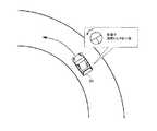
ECU15は、求められた自信度に基づいて、車線又は白線は認識されているが認識精度が悪いと判定し、且つ、車両10の走路にカーブ路が含まれると判定した場合、図2に示すように、車両10がカーブ路の内側寄りを走行するように目標走路にオフセットを加える。 When the
(走路追従制御処理)
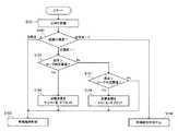
次に、以上のように構成された走行支援装置100を搭載する車両10の、主に走行中に実行される走路追従制御処理について、図3のフローチャートを参照して説明する。(Runway tracking control process)
Next, the track following control process that is mainly executed during the travel of the
図3において、ECU15は、先ず、車載カメラ11により撮像された画像に対して車線認識処理を施し、例えば道路上の白線の認識を試みる(ステップS101)。この際、ECU15は、例えば撮像画像中の白線領域のエッジ数等に応じた自信度を取得する。また、ECU15は、車線認識処理の結果からカーブ半径Rを取得する。 In FIG. 3, the
本実施形態では、白線が精度良く認識されている場合の自信度を“2”と、白線が認識されているが精度が悪い場合の自信度を“1”と、白線が認識されていない場合の自信度を“0”とする。 In this embodiment, the confidence level when the white line is recognized with high accuracy is “2”, the confidence level when the white line is recognized but the accuracy is low is “1”, and the white line is not recognized. The confidence level of “0” is “0”.
次に、ECU15は、取得された自信度がどの程度であるかを判定する(ステップS102)。自信度が“2”であると判定された場合(ステップS102:自信度=2)、ECU15は、例えば目標走路が車線の中央になるように設定して、走路追従制御を継続する(ステップS103)。 Next, the
自信度が“0”であると判定された場合(ステップS102:自信度=0)、ECU15は、走路追従制御を中止する(ステップS104)。この際、ECU15は、走路追従制御を中止することを、車両10の運転者に対して報知する。 When it is determined that the confidence level is “0” (step S102: confidence level = 0), the
自信度が“1”であると判定された場合(ステップS102:自信度=1)、ECU15は、曲率(即ち、カーブ半径Rの逆数)がカーブ判定閾値より大きいか否かを判定する(ステップS105)。 When it is determined that the confidence level is “1” (step S102: confidence level = 1), the
曲率がカーブ判定閾値より大きいと判定された場合(ステップS105:Yes)、ECU15は、左カーブ路であると認識し、車両10が左カーブ路の内側寄りを走行するように目標走路にオフセット“+α”を加える(ステップS106)。続いて、ECU15は、オフセットが加えられた目標走路に沿って車両10が走行するように、各種アクチュエータ等を制御する(ステップS103)。 When it is determined that the curvature is larger than the curve determination threshold value (step S105: Yes), the
ステップS105の処理において、曲率がカーブ判定閾値より小さいと判定された場合(ステップS105:No)、ECU15は、曲率が−カーブ判定閾値より大きいか否かを判定する(ステップS107)。 When it is determined in the process of step S105 that the curvature is smaller than the curve determination threshold (step S105: No), the
曲率が−カーブ判定閾値より大きいと判定された場合(ステップS107:Yes)、ECU15は、右カーブ路であると認識し、車両10が右カーブ路の内側寄りを走行するように目標走路にオフセット“−α”を加える(ステップS108)。続いて、ECU15は、オフセットが加えられた目標走路に沿って車両10が走行するように、各種アクチュエータ等を制御する(ステップS103)。 When it is determined that the curvature is larger than the −curve determination threshold value (step S107: Yes), the
曲率が−カーブ判定閾値より小さいと判定された場合(ステップS107:No)、ECU15は、直線路であると認識し、例えば目標走路が車線の中央になるように設定して、走路追従制御を継続する(ステップS103)。 When it is determined that the curvature is smaller than the −curve determination threshold (step S107: No), the
尚、オフセット“+α”及び“−α”は、例えば道路幅等から決定される適合値とすればよい。 The offsets “+ α” and “−α” may be adapted values determined from, for example, the road width.
(比較例)
ここで、比較例に係る走路追従制御処理について、図4及び図5を参照して説明する。図4は、比較例に係る走路追従制御の一例を示す概念図である。図5は、比較例に係る走路追従制御の他の例を示す概念図である。(Comparative example)
Here, the track following control process according to the comparative example will be described with reference to FIGS. 4 and 5. FIG. 4 is a conceptual diagram showing an example of the track following control according to the comparative example. FIG. 5 is a conceptual diagram illustrating another example of the track following control according to the comparative example.
走路追従制御処理により、車両20が車線中央に設定された目標走路に沿うようにカーブ路を走行している場合、車両20のECUは、所定の操舵角となるような操舵トルクを出力するようにステアリングアクチュエータを制御する。この結果、ステアリングホイルに操舵トルクが付加される(図4参照)。 When the
上記のように、走路追従制御処理によりカーブ路を走行している場合に、例えば白線が認識できないこと等に起因して、走路追従制御処理が中止されると、ステアリングホイルに付加されていた操舵トルクがなくなってしまう(図5参照)。すると、ステアリングホイルは中立点に戻ろうとするので、車両20の車速や運転者の反応速度によっては、車両20がカーブ路(車線)の外側に逸脱してしまう可能性がある。 As described above, when driving on a curved road by the road following control process, if the road following control process is stopped due to, for example, a white line not being recognized, the steering added to the steering wheel Torque is lost (see FIG. 5). Then, since the steering wheel tries to return to the neutral point, the
しかるに本実施形態では、上述の如く、白線が認識されているものの認識精度が悪い場合であり、且つ車両10がカーブ路を走行している場合には、車両10がカーブ路の内側寄りを走行するように目標走路にオフセットが加えられる。このため、仮に走路追従制御処理が中止されたとしても、車両10がカーブ路の外側に逸脱するまでの期間を長くすることができる。従って、走路追従制御が中止された場合であっても、車両10の運転者は、余裕を持って車両10が車線を維持するような操舵を行うことができる。 However, in the present embodiment, as described above, the white line is recognized, but the recognition accuracy is poor, and when the
尚、本実施形態に係る「ECU15」は、本発明に係る「オフセット付与手段」の一例である。 The “
<変形例>
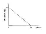
次に、第1実施形態に係る走行支援装置の変形例について、図6を参照して説明する。図6は、画像認識に係る認識率とオフセット量との関係を規定するマップの一例である。<Modification>
Next, a modified example of the driving support apparatus according to the first embodiment will be described with reference to FIG. FIG. 6 is an example of a map that defines the relationship between the recognition rate related to image recognition and the offset amount.
変形例に係る走路追従制御処理では、オフセット量が認識率(上述の実施形態における“自信度”に相当)に応じて変化する。具体的には例えば、図6に示すように、白線の認識精度が良いほど(つまり、認識率が高いほど)、オフセット量が少なくなるように設定される。このように構成すれば、認識率に応じた適切なオフセット量を加えることができ、実用上非常に有利である。 In the track following control process according to the modification, the offset amount changes according to the recognition rate (corresponding to “confidence level” in the above-described embodiment). Specifically, for example, as shown in FIG. 6, the offset amount is set to be smaller as the white line recognition accuracy is higher (that is, the recognition rate is higher). If comprised in this way, the appropriate offset amount according to a recognition rate can be added, and it is very advantageous practically.
<第2実施形態>
第2実施形態に係る走行支援装置について、図7乃至図9を参照して説明する。<Second Embodiment>
A travel support apparatus according to a second embodiment will be described with reference to FIGS.
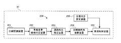
先ず、第2実施形態に係る車両の構成について、図7を参照して説明する。図7は、第2実施形態に係る車両の構成を示すブロック図である。尚、図7には、本発明に直接関連する構成を示し、その他の部材については図示を省略している。 First, the configuration of the vehicle according to the second embodiment will be described with reference to FIG. FIG. 7 is a block diagram illustrating a configuration of the vehicle according to the second embodiment. FIG. 7 shows a configuration directly related to the present invention, and illustration of other members is omitted.
図7において、車両30は、走行支援装置200を備えて構成されている。該走行支援装置200は、白線認識装置201、車線変更継続判定装置202、道路形状推定装置203、目標操舵角演算装置204、車両制御装置205及び自車向き推定装置206を備えて構成されている。 In FIG. 7, the
例えば車載カメラ、プロセッサ等を備えてなる白線認識装置201は、撮像された車両30の前方画像に対して車線認識処理を施して、道路上の白線を認識する。この際、白線認識装置31は、車線認識に係る自信度、並びに、認識された白線に係る曲率、カーブ方向及びヨー角を求める。 For example, the white
例えばメモリ、プロセッサ等を備えてなる車線変更継続判定装置202は、白線認識装置201により求められた自信度に基づいて、車線変更処理が継続可能か否かを判定する。 For example, the lane change
例えばメモリ、プロセッサ等を備えてなる道路形状推定装置203は、白線認識装置201により求められた白線に係る曲率等に基づいて、車両30が走行する道路の形状を推定する。 For example, the road
例えばメモリ、プロセッサ等を備えてなる目標操舵角演算装置204は、車線変更処理が実行されている際に自信度が低下した場合に、推定された道路の形状等を考慮して、車両30が車線を逸脱するまでの時間が増えるように、目標操舵角を演算する。 For example, the target steering
例えばメモリ、プロセッサ等を備えてなる車両制御装置205は、制御目標値(例えば、目標操舵角等)に応じて車両30を制御する。 For example, the
例えばヨーレートセンサ、プロセッサ等を備えてなる自車向き推定装置206は、車線認識に係る自信度が低下した場合に、ヨーレートセンサの出力を積分することによって車両30のヨー角を推定する。 For example, the vehicle
(車線変更制御処理)
次に、以上のように構成された走行支援装置200を搭載する車両20の走行中に実行される車線変更制御処理について、図8のフローチャートを参照して説明する。(Lane change control processing)
Next, the lane change control process executed while the
走行支援装置200により、車両30が現在走行している車線から、該車線に隣接する車線へ変更するように目標走路が設定され、該設定された目標走路に沿うように車両30が制御される車線変更制御処理が開始されたとする。 The
図8において、白線認識装置201は、撮像された画像に対して車線認識処理を施し、道路上の白線の認識を試みる(ステップS201)。この際、白線認識装置201は、例えば撮像画像中の白線領域のエッジ数等に応じた自信度を取得する。また、白線認識装置201は、車線認識処理の結果から、白線に係る曲率、カーブ方向及びヨー角を取得する。 In FIG. 8, the white
次に、車線変更継続判定装置202は、取得された自信度が“2”であるか否かを判定する(ステップS202)。尚、本実施形態では、白線が精度良く認識されている場合の自信度を“2”と、白線が認識されているが精度が悪い場合の自信度を“1”と、白線が認識されていない場合の自信度を“0”とする。 Next, the lane change
自信度が“2”であると判定された場合(ステップS202:Yes)、車線変更継続装置により車両30に係る車線変更が継続される(ステップS203)。他方、自信度が“2”でないと判定された場合(ステップS202:No)、道路形状推定装置203は、取得された白線に係る曲率が、閾値(1/r)未満であるか否かを判定する(ステップS204)。 When it is determined that the degree of confidence is “2” (step S202: Yes), the lane change related to the
取得された白線に係る曲率が閾値未満である(即ち、直線路である)と判定された場合(ステップS204:Yes)、目標操舵角演算装置204は、下記式(1)に従って操舵角δを演算する(ステップS205)。 When it is determined that the obtained curvature relating to the white line is less than the threshold (that is, a straight road) (step S204: Yes), the target steering

次に、車両制御装置205は、演算された操舵角δとなるように車両30を制御する(ステップS208)。 Next, the
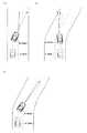
ここで具体的な車両30の走路について、図9(a)を参照して説明を加える。図9では、時刻t1に車線変更制御処理が開始され、時刻t2に自信度が低下したものとする。また、点線は車線変更制御処理において設定された目標走路を示している。 Here, a specific running path of the
図9(a)において、自信度が低下した場合に何らの対応も採られなければ、転舵しているため、車両30は破線矢印のように走行する。すると、運転者が車線変更制御の中止を認識して対応動作を行うまでの時間的な余裕が比較的少なくなるおそれがある。しかるに本実施形態では、操舵角が上記式(1)に従って変更されるので、車両30は実線矢印のように走行する。従って、運転者が余裕を持って自車両を操舵することができる。 In FIG. 9A, if no response is taken when the degree of confidence decreases, the
尚、ステップS208の処理の後(つまり、車線変更制御が中止された後)、車線変更を継続するか否かは、例えば車両30の状況等を考慮して運転者が判断することとなる。 Note that after the process of step S208 (that is, after the lane change control is stopped), the driver determines whether or not to continue the lane change in consideration of, for example, the situation of the
ステップS204の処理において、取得された白線に係る曲率が閾値以上である(即ち、カーブ路である)と判定された場合(ステップS204:No)、目標操舵角演算装置204は、車線変更に起因する車両30の転舵方向と、カーブ路を走行するための車両30の転舵方向とが同じか否かを判定する(ステップS206)。 In the process of step S204, when it is determined that the curvature related to the acquired white line is equal to or greater than the threshold (that is, a curved road) (step S204: No), the target steering
車線変更に起因する車両30の転舵方向と、カーブ路を走行するための車両30の転舵方向とが同じであると判定された場合(ステップS206)、目標操舵角演算装置204は、現在の操舵角を維持するように目標操舵角を設定する(ステップS207)。次、車両制御装置205は、設定された操舵角δとなるように車両30を制御する(ステップS208)。 When it is determined that the turning direction of the
ここで具体的な車両30の走路について、図9(c)を参照して説明を加える。車線変更に起因する車両30の転舵方向と、カーブ路を走行するための車両30の転舵方向とが同じであるため、自信度が低下した際の操舵角を維持すれば、車両30は、図9(c)における実線矢印のように走行する。従って、運転者が車線変更制御の中止を認識した後、余裕を持って自車両を操舵することができる。 Here, a specific running path of the
ステップS206の処理において、車線変更に起因する車両30の転舵方向と、カーブ路を走行するための車両30の転舵方向とが異なると判定された場合(ステップS206:No)、目標操舵角演算装置204は、上記式(1)に従って操舵角δを演算する(ステップS205)。次に、車両制御装置205は、演算された操舵角δとなるように車両30を制御する(ステップS208)。 In the process of step S206, when it is determined that the turning direction of the
ここで具体的な車両30の走路について、図9(b)を参照して説明を加える。図9(b)において、自信度が低下した場合に何らの対応も採られなければ、転舵しているため、車両30は破線矢印のように走行する。すると、運転者が車線変更制御の中止を認識して対応動作を行うまでの時間的な余裕が比較的少なくなるおそれがある。しかるに本実施形態では、操舵角が上記式(1)に従って変更されるので、車両30は実線矢印のように走行する。従って、運転者が余裕を持って自車両を操舵することができる。 Here, a specific running path of the
尚、道路上の白線を認識することが困難になった後は、自車向き推定装置206は、ヨーレートセンサの出力を積分することによって車両30のヨー角を推定し、該推定されたヨー角を示す信号を車両制御装置205に送信する(ステップS209)。 After it becomes difficult to recognize the white line on the road, the vehicle
本実施形態に係る「目標操舵角演算装置204」及び「車両制御装置205」は、本発明に係る「操舵角制御手段」の一例である。 The “target steering
<第1変形例>
次に、第2実施形態に係る走行支援装置の第1変形例について説明する。本変形例では、上述したステップS205の処理において、上記式(1)に代えて、「車両30に係る最大操舵角度」と「自信度低下による車線変更の継続が不可能と判定されてからの経過時間」との積により、操舵角δが演算される。<First Modification>
Next, a first modification of the travel support device according to the second embodiment will be described. In this modification, in the process of step S205 described above, instead of the above formula (1), it is determined that “the maximum steering angle relating to the
このように構成すれば、乗り心地は多少損なわれるが、上記式(1)により操舵角δを演算した場合に比べて、短時間で車両30の向きを変更することができる。この結果、運転者が車線変更制御の中止を認識して対応動作を行うまでの時間的な余裕をより増やすことができる。 With such a configuration, although the riding comfort is somewhat impaired, the direction of the
<第2変形例>
次に、第2実施形態に係る走行支援装置の第2変形例について、図10のフローチャートを参照して説明する。<Second Modification>
Next, a second modification of the travel support apparatus according to the second embodiment will be described with reference to the flowchart of FIG.
本変形例では、車両30は、ドライバ状態判断装置を更に備えて構成されている。ここでドライバ状態判断装置は、例えば運転者の顔の向きや、まぶたの開度等を検出することにより、運転者が異常に対して十分な対応をとれる状態であるか否かを推定する。そして、ドライバ状態判断装置は、推定された運転者の状態を示す信号を目標操舵角演算装置204に送信する(ステップS301)。 In this modification, the
上記ステップS205の処理において、目標操舵角演算装置204は、ドライバ状態判断装置により推定された運転者の状態が、「異常に対して十分な対応をとれる状態」である場合、上記式(1)により操舵角δを演算する。 In the process of step S205, when the driver's state estimated by the driver state determination device is “a state in which sufficient action can be taken against the abnormality”, the target steering
他方、目標操舵角演算装置204は、ドライバ状態判断装置により推定された運転者の状態が、「異常に対して十分な対応をとれない状態」である場合、「車両30に係る最大操舵角度」と「自信度低下による車線変更の継続が不可能と判定されてからの経過時間」との積により、操舵角δを演算する。 On the other hand, when the driver's state estimated by the driver state determination device is “a state in which sufficient action cannot be taken against the abnormality”, the target steering
<第3変形例>
次に、第2実施形態に係る走行支援装置の第3変形例について、図11のフローチャートを参照して説明する。<Third Modification>
Next, a third modification of the travel support apparatus according to the second embodiment will be described with reference to the flowchart of FIG.
本変形例では、車両30は雨計測装置を更に備えて構成されている。ここで雨計測装置は、降雨量を測定して、該測定された降雨量を示す信号を目標操舵角演算装置204に送信する(ステップS401)。 In this modification, the
上記ステップS205の処理において、上記式(1)により操舵角δが演算される場合、目標操舵角演算装置204は、ヨーレートγを求める式(即ち、“γ=θ/t”)に含まれる“t”に、降雨量が多くなる程、大きくなる係数を掛ける。この結果、車両30の旋回速度を抑制することができるので、路面が濡れていることによるスリップを防止することができる。 In the process of step S205, when the steering angle δ is calculated by the above equation (1), the target steering
或いは、上記ステップS205の処理において、「車両30に係る最大操舵角度」と「自信度低下による車線変更の継続が不可能と判定されてからの経過時間」との積により、操舵角δが演算される場合(例えば、第2実施形態の第1変形例参照)、目標操舵角演算装置204は、経過時間に、降雨量が多くなるほど、小さくなる係数を掛ける。この結果、車両30の旋回速度を抑制することができるので、路面が濡れていることによるスリップを防止することができる。 Alternatively, in the process of step S205, the steering angle δ is calculated by the product of “the maximum steering angle associated with the
本発明は、上述した実施形態に限られるものではなく、特許請求の範囲及び明細書全体から読み取れる発明の要旨或いは思想に反しない範囲で適宜変更可能であり、そのような変更を伴う走行支援装置もまた本発明の技術的範囲に含まれるものである。 The present invention is not limited to the above-described embodiment, and can be changed as appropriate without departing from the scope or spirit of the invention that can be read from the claims and the entire specification. Is also included in the technical scope of the present invention.
10、20…車両、11…車載カメラ、12…車速センサ、13…舵角センサ、14…位置センサ、15…ECU、16…スロットルアクチュエータ、17…ブレーキアクチュエータ、18…ステアリングアクチュエータ、100、200…走行支援装置、201…白線認識装置、202…車線変更継続判定装置、203…道路状態推定装置、204…目標操舵角演算装置、205…車両制御装置、206…自車向き推定装置 DESCRIPTION OF
Claims (5)
Translated fromJapanese前記自車両の走路に一のカーブ路が含まれる場合に、前記撮像画像に基づく車線認識の程度を示す情報である自信度に基づいて、前記自車両が前記一のカーブ路の内側寄りを走行するように前記目標走路にオフセットを加えるオフセット付与手段を備える
ことを特徴とする走行支援装置。A travel support device that sets a target runway from a captured image ahead of the host vehicle and controls the host vehicle to run along the target runway,
When the vehicle's running path includes one curved road, the own vehicle travels closer to the inside of the one curved road based on the degree of confidence that is information indicating the degree of lane recognition based on the captured image. A driving support apparatus comprising offset providing means for adding an offset to the target road.
他のカーブ路における前記車線変更制御の実行中に前記自信度が低下した場合であって、前記他のカーブ路を走行するための転舵方向と、前記車線変更制御に起因する転舵方向と、が同じ場合に、前記自信度が低下する直前の操舵角を維持するように前記自車両を制御する操舵角制御手段を更に備える
ことを特徴とする請求項1に記載の走行支援装置。The travel support device is capable of executing lane change control in which the target lane is set so as to change from one lane in which the host vehicle is currently traveling to another lane adjacent to the one lane,
When the degree of confidence decreases during execution of the lane change control on another curved road, a steering direction for traveling on the other curved road, and a steering direction resulting from the lane change control, 2. The driving support device according to claim 1, further comprising: a steering angle control unit that controls the host vehicle so as to maintain a steering angle immediately before the degree of self-confidence decreases when the two are equal.
他のカーブ路における前記車線変更制御の実行中に前記自信度が低下した場合であって、前記他のカーブ路を走行するための転舵方向と、前記車線変更制御に起因する転舵方向と、が異なる場合に、前記車線変更制御にかかる所要時間と前記車線変更制御が開始されてから前記自信度が低下するまでの時間とにより求まる残り時間と、前記自車両に係るヨー角及び車速と、に基づいて操舵角を演算し、前記演算された操舵角となるように前記自車両を制御する操舵角制御手段を更に備える
ことを特徴とする請求項1に記載の走行支援装置。The travel support device is capable of executing lane change control in which the target lane is set so as to change from one lane in which the host vehicle is currently traveling to another lane adjacent to the one lane,
When the degree of confidence decreases during execution of the lane change control on another curved road, a steering direction for traveling on the other curved road, and a steering direction resulting from the lane change control, , And the remaining time obtained from the time required for the lane change control and the time from when the lane change control is started until the confidence level decreases, the yaw angle and the vehicle speed related to the host vehicle, The driving support device according to claim 1, further comprising: a steering angle control unit that calculates a steering angle based on and controls the host vehicle so that the calculated steering angle is obtained.
Priority Applications (1)
| Application Number | Priority Date | Filing Date | Title |
|---|---|---|---|
| JP2013002577AJP6123297B2 (en) | 2013-01-10 | 2013-01-10 | Driving support device |
Applications Claiming Priority (1)
| Application Number | Priority Date | Filing Date | Title |
|---|---|---|---|
| JP2013002577AJP6123297B2 (en) | 2013-01-10 | 2013-01-10 | Driving support device |
Publications (2)
| Publication Number | Publication Date |
|---|---|
| JP2014133477Atrue JP2014133477A (en) | 2014-07-24 |
| JP6123297B2 JP6123297B2 (en) | 2017-05-10 |
Family
ID=51412116
Family Applications (1)
| Application Number | Title | Priority Date | Filing Date |
|---|---|---|---|
| JP2013002577AActiveJP6123297B2 (en) | 2013-01-10 | 2013-01-10 | Driving support device |
Country Status (1)
| Country | Link |
|---|---|
| JP (1) | JP6123297B2 (en) |
Cited By (15)
| Publication number | Priority date | Publication date | Assignee | Title |
|---|---|---|---|---|
| WO2016031647A1 (en)* | 2014-08-25 | 2016-03-03 | クラリオン株式会社 | Autonomous driving control device |
| JP2016037266A (en)* | 2014-08-11 | 2016-03-22 | 日産自動車株式会社 | Travelling control device and travelling control method |
| JP2016124310A (en)* | 2014-12-26 | 2016-07-11 | 富士重工業株式会社 | Traveling control device of vehicle |
| JP2017128277A (en)* | 2016-01-21 | 2017-07-27 | 株式会社デンソー | Travel control device |
| JP2017149186A (en)* | 2016-02-22 | 2017-08-31 | 本田技研工業株式会社 | Vehicle travel control device |
| JP2018114930A (en)* | 2017-01-20 | 2018-07-26 | トヨタ自動車株式会社 | Driving assistance device |
| CN108995652A (en)* | 2017-06-06 | 2018-12-14 | 丰田自动车株式会社 | Handling maneuver auxiliary device |
| JP2019089549A (en)* | 2019-01-29 | 2019-06-13 | 株式会社Subaru | Vehicle travel control device |
| JP2019107944A (en)* | 2017-12-15 | 2019-07-04 | 株式会社デンソー | Vehicle control device |
| WO2020157408A1 (en)* | 2019-01-31 | 2020-08-06 | Psa Automobiles Sa | Method for managing a maintenance support functionality in the lane provided by a driver assistance system of a motor-driven land vehicle |
| US10875530B2 (en) | 2017-08-30 | 2020-12-29 | Nissan Motor Co., Ltd. | Travel control method and travel control device for drive-assisted vehicle |
| US11260859B2 (en) | 2017-09-01 | 2022-03-01 | Honda Motor Co., Ltd. | Vehicle control system, vehicle control method, and storage medium |
| CN114802234A (en)* | 2022-04-22 | 2022-07-29 | 岚图汽车科技有限公司 | Road edge avoiding method and system in intelligent cruise |
| WO2024048073A1 (en)* | 2022-08-30 | 2024-03-07 | 株式会社アイシン | Driving assistance device and computer program |
| US12157466B2 (en) | 2022-03-15 | 2024-12-03 | Toyota Jidosha Kabushiki Kaisha | Vehicle controller, and method and computer program for controlling vehicle |
Citations (5)
| Publication number | Priority date | Publication date | Assignee | Title |
|---|---|---|---|---|
| JP2001344687A (en)* | 2000-06-02 | 2001-12-14 | Mitsubishi Electric Corp | Vehicle steering driving support device |
| JP2002002427A (en)* | 2000-06-15 | 2002-01-09 | Mazda Motor Corp | Control device for vehicle |
| JP2003327012A (en)* | 2002-05-13 | 2003-11-19 | Mitsubishi Electric Corp | Travel control device for vehicles |
| JP2009214785A (en)* | 2008-03-12 | 2009-09-24 | Honda Motor Co Ltd | Vehicle travel support device, vehicle, and vehicle travel support program |
| JP2012066778A (en)* | 2010-09-27 | 2012-04-05 | Toyota Motor Corp | Travel trace generation device |
- 2013
- 2013-01-10JPJP2013002577Apatent/JP6123297B2/enactiveActive
Patent Citations (5)
| Publication number | Priority date | Publication date | Assignee | Title |
|---|---|---|---|---|
| JP2001344687A (en)* | 2000-06-02 | 2001-12-14 | Mitsubishi Electric Corp | Vehicle steering driving support device |
| JP2002002427A (en)* | 2000-06-15 | 2002-01-09 | Mazda Motor Corp | Control device for vehicle |
| JP2003327012A (en)* | 2002-05-13 | 2003-11-19 | Mitsubishi Electric Corp | Travel control device for vehicles |
| JP2009214785A (en)* | 2008-03-12 | 2009-09-24 | Honda Motor Co Ltd | Vehicle travel support device, vehicle, and vehicle travel support program |
| JP2012066778A (en)* | 2010-09-27 | 2012-04-05 | Toyota Motor Corp | Travel trace generation device |
Cited By (22)
| Publication number | Priority date | Publication date | Assignee | Title |
|---|---|---|---|---|
| JP2016037266A (en)* | 2014-08-11 | 2016-03-22 | 日産自動車株式会社 | Travelling control device and travelling control method |
| JP2016045101A (en)* | 2014-08-25 | 2016-04-04 | クラリオン株式会社 | Automatic drive control device |
| US10168702B2 (en) | 2014-08-25 | 2019-01-01 | Clarion Co., Ltd. | Autonomous driving control device |
| WO2016031647A1 (en)* | 2014-08-25 | 2016-03-03 | クラリオン株式会社 | Autonomous driving control device |
| JP2016124310A (en)* | 2014-12-26 | 2016-07-11 | 富士重工業株式会社 | Traveling control device of vehicle |
| JP2017128277A (en)* | 2016-01-21 | 2017-07-27 | 株式会社デンソー | Travel control device |
| JP2017149186A (en)* | 2016-02-22 | 2017-08-31 | 本田技研工業株式会社 | Vehicle travel control device |
| JP2018114930A (en)* | 2017-01-20 | 2018-07-26 | トヨタ自動車株式会社 | Driving assistance device |
| US10870446B2 (en) | 2017-06-06 | 2020-12-22 | Toyota Jidosha Kabushiki Kaisha | Steering assist device |
| CN108995652A (en)* | 2017-06-06 | 2018-12-14 | 丰田自动车株式会社 | Handling maneuver auxiliary device |
| JP2018203100A (en)* | 2017-06-06 | 2018-12-27 | トヨタ自動車株式会社 | Steering assistance device |
| CN108995652B (en)* | 2017-06-06 | 2021-07-20 | 丰田自动车株式会社 | Steering Aid |
| US10875530B2 (en) | 2017-08-30 | 2020-12-29 | Nissan Motor Co., Ltd. | Travel control method and travel control device for drive-assisted vehicle |
| US11260859B2 (en) | 2017-09-01 | 2022-03-01 | Honda Motor Co., Ltd. | Vehicle control system, vehicle control method, and storage medium |
| JP2019107944A (en)* | 2017-12-15 | 2019-07-04 | 株式会社デンソー | Vehicle control device |
| JP2019089549A (en)* | 2019-01-29 | 2019-06-13 | 株式会社Subaru | Vehicle travel control device |
| FR3092303A1 (en)* | 2019-01-31 | 2020-08-07 | Psa Automobiles Sa | A method of managing a lane keeping assistance functionality provided by a driving assistance system of a land motor vehicle |
| WO2020157408A1 (en)* | 2019-01-31 | 2020-08-06 | Psa Automobiles Sa | Method for managing a maintenance support functionality in the lane provided by a driver assistance system of a motor-driven land vehicle |
| CN113396095A (en)* | 2019-01-31 | 2021-09-14 | 标致雪铁龙汽车股份有限公司 | Method for managing a lane keeping aid function provided by a driving aid system of an engine-driven land vehicle |
| US12157466B2 (en) | 2022-03-15 | 2024-12-03 | Toyota Jidosha Kabushiki Kaisha | Vehicle controller, and method and computer program for controlling vehicle |
| CN114802234A (en)* | 2022-04-22 | 2022-07-29 | 岚图汽车科技有限公司 | Road edge avoiding method and system in intelligent cruise |
| WO2024048073A1 (en)* | 2022-08-30 | 2024-03-07 | 株式会社アイシン | Driving assistance device and computer program |
Also Published As
| Publication number | Publication date |
|---|---|
| JP6123297B2 (en) | 2017-05-10 |
Similar Documents
| Publication | Publication Date | Title |
|---|---|---|
| JP6123297B2 (en) | Driving support device | |
| US9911330B2 (en) | Driving assistance device and driving assistance method | |
| RU2721387C1 (en) | Method for prediction of action and device for prediction of action of motion assistance device | |
| JP5141849B2 (en) | Vehicle travel support device | |
| JP5130638B2 (en) | Avoidance operation calculation device, avoidance control device, vehicle including each device, avoidance operation calculation method, and avoidance control method | |
| JP6911693B2 (en) | Driving support control system | |
| JP6432679B2 (en) | Stop position setting apparatus and method | |
| CN107107751B (en) | Target vehicle speed generation device and travel control device | |
| US20160314360A1 (en) | Lane detection device and method thereof, curve starting point detection device and method thereof, and steering assistance device and method thereof | |
| JP6363516B2 (en) | Vehicle travel control device | |
| US20150307095A1 (en) | Driving assistance apparatus | |
| US10994731B2 (en) | Steering assistance device and steering assistance method | |
| JP6377942B2 (en) | Driving assistance device | |
| WO2013018537A1 (en) | Driving assistance apparatus and driving assistance method | |
| KR20130009085A (en) | Smart cruise control system applying variable curvature and method thereof | |
| CN103832435A (en) | Lane-keeping control device | |
| JP6973978B2 (en) | Control device and control method to control the behavior of the motorcycle during lane splitting | |
| US11148716B2 (en) | Steering assistance device and steering assistance method | |
| CN110446641A (en) | Controller of vehicle and control method for vehicle | |
| US12198444B2 (en) | Method for controlling the positioning of a motor vehicle on a traffic lane | |
| US20200307612A1 (en) | Vehicle control device | |
| US20180037232A1 (en) | Method and device for adapting a vehicle velocity for a vehicle | |
| JP2008059366A (en) | Steering angle determination device, automobile and steering angle determination method | |
| JP7243227B2 (en) | vehicle controller | |
| CN116118770A (en) | Adaptive rationalizer for vehicle perception systems for robust autonomous driving control |
Legal Events
| Date | Code | Title | Description |
|---|---|---|---|
| A621 | Written request for application examination | Free format text:JAPANESE INTERMEDIATE CODE: A621 Effective date:20150513 | |
| A131 | Notification of reasons for refusal | Free format text:JAPANESE INTERMEDIATE CODE: A131 Effective date:20160315 | |
| A977 | Report on retrieval | Free format text:JAPANESE INTERMEDIATE CODE: A971007 Effective date:20160317 | |
| A521 | Request for written amendment filed | Free format text:JAPANESE INTERMEDIATE CODE: A523 Effective date:20160404 | |
| A131 | Notification of reasons for refusal | Free format text:JAPANESE INTERMEDIATE CODE: A131 Effective date:20160426 | |
| A521 | Request for written amendment filed | Free format text:JAPANESE INTERMEDIATE CODE: A523 Effective date:20160610 | |
| A131 | Notification of reasons for refusal | Free format text:JAPANESE INTERMEDIATE CODE: A131 Effective date:20161108 | |
| A521 | Request for written amendment filed | Free format text:JAPANESE INTERMEDIATE CODE: A523 Effective date:20161219 | |
| A131 | Notification of reasons for refusal | Free format text:JAPANESE INTERMEDIATE CODE: A131 Effective date:20170214 | |
| A521 | Request for written amendment filed | Free format text:JAPANESE INTERMEDIATE CODE: A523 Effective date:20170222 | |
| TRDD | Decision of grant or rejection written | ||
| A01 | Written decision to grant a patent or to grant a registration (utility model) | Free format text:JAPANESE INTERMEDIATE CODE: A01 Effective date:20170307 | |
| A61 | First payment of annual fees (during grant procedure) | Free format text:JAPANESE INTERMEDIATE CODE: A61 Effective date:20170320 | |
| R151 | Written notification of patent or utility model registration | Ref document number:6123297 Country of ref document:JP Free format text:JAPANESE INTERMEDIATE CODE: R151 |