JP2014131370A - Wireless power supply device for electrically driven mobile body - Google Patents
Wireless power supply device for electrically driven mobile bodyDownload PDFInfo
- Publication number
- JP2014131370A JP2014131370AJP2012286526AJP2012286526AJP2014131370AJP 2014131370 AJP2014131370 AJP 2014131370AJP 2012286526 AJP2012286526 AJP 2012286526AJP 2012286526 AJP2012286526 AJP 2012286526AJP 2014131370 AJP2014131370 AJP 2014131370A
- Authority
- JP
- Japan
- Prior art keywords
- primary coils
- mobile body
- pair
- wireless power
- secondary coil
- Prior art date
- Legal status (The legal status is an assumption and is not a legal conclusion. Google has not performed a legal analysis and makes no representation as to the accuracy of the status listed.)
- Granted
Links
- 230000005291magnetic effectEffects0.000claimsabstractdescription115
- 230000004907fluxEffects0.000claimsabstractdescription36
- 239000004020conductorSubstances0.000claimsdescription35
- 229920005989resinPolymers0.000claimsdescription29
- 239000011347resinSubstances0.000claimsdescription29
- 238000003860storageMethods0.000abstractdescription18
- 230000001965increasing effectEffects0.000abstractdescription9
- 230000005611electricityEffects0.000abstractdescription3
- 238000004804windingMethods0.000description10
- 229910000859α-FeInorganic materials0.000description8
- 238000000034methodMethods0.000description7
- 238000006073displacement reactionMethods0.000description5
- 230000000694effectsEffects0.000description5
- 238000009434installationMethods0.000description5
- 239000000463materialSubstances0.000description5
- 229910052751metalInorganic materials0.000description5
- 239000002184metalSubstances0.000description5
- XEEYBQQBJWHFJM-UHFFFAOYSA-NIronChemical compound[Fe]XEEYBQQBJWHFJM-UHFFFAOYSA-N0.000description4
- 229910052782aluminiumInorganic materials0.000description4
- XAGFODPZIPBFFR-UHFFFAOYSA-NaluminiumChemical compound[Al]XAGFODPZIPBFFR-UHFFFAOYSA-N0.000description4
- 230000001976improved effectEffects0.000description4
- 239000003973paintSubstances0.000description4
- RYGMFSIKBFXOCR-UHFFFAOYSA-NCopperChemical compound[Cu]RYGMFSIKBFXOCR-UHFFFAOYSA-N0.000description3
- 230000008859changeEffects0.000description3
- 229910052802copperInorganic materials0.000description3
- 239000010949copperSubstances0.000description3
- 238000010586diagramMethods0.000description3
- 230000005674electromagnetic inductionEffects0.000description3
- 239000003302ferromagnetic materialSubstances0.000description3
- -1fluororesinPolymers0.000description3
- 230000003993interactionEffects0.000description3
- 239000000696magnetic materialSubstances0.000description3
- 238000004519manufacturing processMethods0.000description3
- NIXOWILDQLNWCW-UHFFFAOYSA-Nacrylic acid groupChemical groupC(C=C)(=O)ONIXOWILDQLNWCW-UHFFFAOYSA-N0.000description2
- 238000010276constructionMethods0.000description2
- 230000020169heat generationEffects0.000description2
- 229910052742ironInorganic materials0.000description2
- 230000000630rising effectEffects0.000description2
- 229920000178Acrylic resinPolymers0.000description1
- 239000004925Acrylic resinSubstances0.000description1
- 229910000838Al alloyInorganic materials0.000description1
- JOYRKODLDBILNP-UHFFFAOYSA-NEthyl urethaneChemical compoundCCOC(N)=OJOYRKODLDBILNP-UHFFFAOYSA-N0.000description1
- YCKRFDGAMUMZLT-UHFFFAOYSA-NFluorine atomChemical compound[F]YCKRFDGAMUMZLT-UHFFFAOYSA-N0.000description1
- HBBGRARXTFLTSG-UHFFFAOYSA-NLithium ionChemical compound[Li+]HBBGRARXTFLTSG-UHFFFAOYSA-N0.000description1
- 239000004698PolyethyleneSubstances0.000description1
- 239000004743PolypropyleneSubstances0.000description1
- 230000001133accelerationEffects0.000description1
- 238000009825accumulationMethods0.000description1
- 229920000122acrylonitrile butadiene styrenePolymers0.000description1
- 239000003990capacitorSubstances0.000description1
- 230000001413cellular effectEffects0.000description1
- 238000007796conventional methodMethods0.000description1
- 238000001816coolingMethods0.000description1
- 239000000498cooling waterSubstances0.000description1
- 238000005260corrosionMethods0.000description1
- 230000007797corrosionEffects0.000description1
- 238000013461designMethods0.000description1
- 238000009792diffusion processMethods0.000description1
- 239000000428dustSubstances0.000description1
- 230000002500effect on skinEffects0.000description1
- 238000005516engineering processMethods0.000description1
- 239000003822epoxy resinSubstances0.000description1
- 239000011737fluorineSubstances0.000description1
- 229910052731fluorineInorganic materials0.000description1
- 230000014509gene expressionEffects0.000description1
- 230000017525heat dissipationEffects0.000description1
- 238000010438heat treatmentMethods0.000description1
- 230000001939inductive effectEffects0.000description1
- 239000012212insulatorSubstances0.000description1
- 229910001416lithium ionInorganic materials0.000description1
- 230000004048modificationEffects0.000description1
- 238000012986modificationMethods0.000description1
- 230000000149penetrating effectEffects0.000description1
- 229920000647polyepoxidePolymers0.000description1
- 229920000573polyethylenePolymers0.000description1
- 229920001155polypropylenePolymers0.000description1
- 230000001737promoting effectEffects0.000description1
- 230000005855radiationEffects0.000description1
- 230000001105regulatory effectEffects0.000description1
- 230000007480spreadingEffects0.000description1
- 238000003892spreadingMethods0.000description1
- 239000010935stainless steelSubstances0.000description1
- 229910001220stainless steelInorganic materials0.000description1
- 238000012546transferMethods0.000description1
- 229920006337unsaturated polyester resinPolymers0.000description1
Images


Classifications
- H—ELECTRICITY
- H01—ELECTRIC ELEMENTS
- H01F—MAGNETS; INDUCTANCES; TRANSFORMERS; SELECTION OF MATERIALS FOR THEIR MAGNETIC PROPERTIES
- H01F38/00—Adaptations of transformers or inductances for specific applications or functions
- H01F38/14—Inductive couplings
- B—PERFORMING OPERATIONS; TRANSPORTING
- B60—VEHICLES IN GENERAL
- B60L—PROPULSION OF ELECTRICALLY-PROPELLED VEHICLES; SUPPLYING ELECTRIC POWER FOR AUXILIARY EQUIPMENT OF ELECTRICALLY-PROPELLED VEHICLES; ELECTRODYNAMIC BRAKE SYSTEMS FOR VEHICLES IN GENERAL; MAGNETIC SUSPENSION OR LEVITATION FOR VEHICLES; MONITORING OPERATING VARIABLES OF ELECTRICALLY-PROPELLED VEHICLES; ELECTRIC SAFETY DEVICES FOR ELECTRICALLY-PROPELLED VEHICLES
- B60L53/00—Methods of charging batteries, specially adapted for electric vehicles; Charging stations or on-board charging equipment therefor; Exchange of energy storage elements in electric vehicles
- B60L53/30—Constructional details of charging stations
- B60L53/35—Means for automatic or assisted adjustment of the relative position of charging devices and vehicles
- B60L53/38—Means for automatic or assisted adjustment of the relative position of charging devices and vehicles specially adapted for charging by inductive energy transfer
- B60L53/39—Means for automatic or assisted adjustment of the relative position of charging devices and vehicles specially adapted for charging by inductive energy transfer with position-responsive activation of primary coils
- H—ELECTRICITY
- H01—ELECTRIC ELEMENTS
- H01F—MAGNETS; INDUCTANCES; TRANSFORMERS; SELECTION OF MATERIALS FOR THEIR MAGNETIC PROPERTIES
- H01F27/00—Details of transformers or inductances, in general
- H01F27/34—Special means for preventing or reducing unwanted electric or magnetic effects, e.g. no-load losses, reactive currents, harmonics, oscillations, leakage fields
- H01F27/36—Electric or magnetic shields or screens
- H01F27/363—Electric or magnetic shields or screens made of electrically conductive material
- H—ELECTRICITY
- H02—GENERATION; CONVERSION OR DISTRIBUTION OF ELECTRIC POWER
- H02J—CIRCUIT ARRANGEMENTS OR SYSTEMS FOR SUPPLYING OR DISTRIBUTING ELECTRIC POWER; SYSTEMS FOR STORING ELECTRIC ENERGY
- H02J50/00—Circuit arrangements or systems for wireless supply or distribution of electric power
- H02J50/005—Mechanical details of housing or structure aiming to accommodate the power transfer means, e.g. mechanical integration of coils, antennas or transducers into emitting or receiving devices
- H—ELECTRICITY
- H02—GENERATION; CONVERSION OR DISTRIBUTION OF ELECTRIC POWER
- H02J—CIRCUIT ARRANGEMENTS OR SYSTEMS FOR SUPPLYING OR DISTRIBUTING ELECTRIC POWER; SYSTEMS FOR STORING ELECTRIC ENERGY
- H02J50/00—Circuit arrangements or systems for wireless supply or distribution of electric power
- H02J50/10—Circuit arrangements or systems for wireless supply or distribution of electric power using inductive coupling
- H—ELECTRICITY
- H02—GENERATION; CONVERSION OR DISTRIBUTION OF ELECTRIC POWER
- H02J—CIRCUIT ARRANGEMENTS OR SYSTEMS FOR SUPPLYING OR DISTRIBUTING ELECTRIC POWER; SYSTEMS FOR STORING ELECTRIC ENERGY
- H02J50/00—Circuit arrangements or systems for wireless supply or distribution of electric power
- H02J50/70—Circuit arrangements or systems for wireless supply or distribution of electric power involving the reduction of electric, magnetic or electromagnetic leakage fields
- H—ELECTRICITY
- H02—GENERATION; CONVERSION OR DISTRIBUTION OF ELECTRIC POWER
- H02J—CIRCUIT ARRANGEMENTS OR SYSTEMS FOR SUPPLYING OR DISTRIBUTING ELECTRIC POWER; SYSTEMS FOR STORING ELECTRIC ENERGY
- H02J50/00—Circuit arrangements or systems for wireless supply or distribution of electric power
- H02J50/90—Circuit arrangements or systems for wireless supply or distribution of electric power involving detection or optimisation of position, e.g. alignment
- B—PERFORMING OPERATIONS; TRANSPORTING
- B60—VEHICLES IN GENERAL
- B60L—PROPULSION OF ELECTRICALLY-PROPELLED VEHICLES; SUPPLYING ELECTRIC POWER FOR AUXILIARY EQUIPMENT OF ELECTRICALLY-PROPELLED VEHICLES; ELECTRODYNAMIC BRAKE SYSTEMS FOR VEHICLES IN GENERAL; MAGNETIC SUSPENSION OR LEVITATION FOR VEHICLES; MONITORING OPERATING VARIABLES OF ELECTRICALLY-PROPELLED VEHICLES; ELECTRIC SAFETY DEVICES FOR ELECTRICALLY-PROPELLED VEHICLES
- B60L2200/00—Type of vehicles
- B60L2200/26—Rail vehicles
- H—ELECTRICITY
- H02—GENERATION; CONVERSION OR DISTRIBUTION OF ELECTRIC POWER
- H02J—CIRCUIT ARRANGEMENTS OR SYSTEMS FOR SUPPLYING OR DISTRIBUTING ELECTRIC POWER; SYSTEMS FOR STORING ELECTRIC ENERGY
- H02J2310/00—The network for supplying or distributing electric power characterised by its spatial reach or by the load
- H02J2310/40—The network being an on-board power network, i.e. within a vehicle
- H02J2310/48—The network being an on-board power network, i.e. within a vehicle for electric vehicles [EV] or hybrid vehicles [HEV]
- Y—GENERAL TAGGING OF NEW TECHNOLOGICAL DEVELOPMENTS; GENERAL TAGGING OF CROSS-SECTIONAL TECHNOLOGIES SPANNING OVER SEVERAL SECTIONS OF THE IPC; TECHNICAL SUBJECTS COVERED BY FORMER USPC CROSS-REFERENCE ART COLLECTIONS [XRACs] AND DIGESTS
- Y02—TECHNOLOGIES OR APPLICATIONS FOR MITIGATION OR ADAPTATION AGAINST CLIMATE CHANGE
- Y02T—CLIMATE CHANGE MITIGATION TECHNOLOGIES RELATED TO TRANSPORTATION
- Y02T10/00—Road transport of goods or passengers
- Y02T10/60—Other road transportation technologies with climate change mitigation effect
- Y02T10/70—Energy storage systems for electromobility, e.g. batteries
- Y—GENERAL TAGGING OF NEW TECHNOLOGICAL DEVELOPMENTS; GENERAL TAGGING OF CROSS-SECTIONAL TECHNOLOGIES SPANNING OVER SEVERAL SECTIONS OF THE IPC; TECHNICAL SUBJECTS COVERED BY FORMER USPC CROSS-REFERENCE ART COLLECTIONS [XRACs] AND DIGESTS
- Y02—TECHNOLOGIES OR APPLICATIONS FOR MITIGATION OR ADAPTATION AGAINST CLIMATE CHANGE
- Y02T—CLIMATE CHANGE MITIGATION TECHNOLOGIES RELATED TO TRANSPORTATION
- Y02T10/00—Road transport of goods or passengers
- Y02T10/60—Other road transportation technologies with climate change mitigation effect
- Y02T10/7072—Electromobility specific charging systems or methods for batteries, ultracapacitors, supercapacitors or double-layer capacitors
- Y—GENERAL TAGGING OF NEW TECHNOLOGICAL DEVELOPMENTS; GENERAL TAGGING OF CROSS-SECTIONAL TECHNOLOGIES SPANNING OVER SEVERAL SECTIONS OF THE IPC; TECHNICAL SUBJECTS COVERED BY FORMER USPC CROSS-REFERENCE ART COLLECTIONS [XRACs] AND DIGESTS
- Y02—TECHNOLOGIES OR APPLICATIONS FOR MITIGATION OR ADAPTATION AGAINST CLIMATE CHANGE
- Y02T—CLIMATE CHANGE MITIGATION TECHNOLOGIES RELATED TO TRANSPORTATION
- Y02T90/00—Enabling technologies or technologies with a potential or indirect contribution to GHG emissions mitigation
- Y02T90/10—Technologies relating to charging of electric vehicles
- Y02T90/12—Electric charging stations
- Y—GENERAL TAGGING OF NEW TECHNOLOGICAL DEVELOPMENTS; GENERAL TAGGING OF CROSS-SECTIONAL TECHNOLOGIES SPANNING OVER SEVERAL SECTIONS OF THE IPC; TECHNICAL SUBJECTS COVERED BY FORMER USPC CROSS-REFERENCE ART COLLECTIONS [XRACs] AND DIGESTS
- Y02—TECHNOLOGIES OR APPLICATIONS FOR MITIGATION OR ADAPTATION AGAINST CLIMATE CHANGE
- Y02T—CLIMATE CHANGE MITIGATION TECHNOLOGIES RELATED TO TRANSPORTATION
- Y02T90/00—Enabling technologies or technologies with a potential or indirect contribution to GHG emissions mitigation
- Y02T90/10—Technologies relating to charging of electric vehicles
- Y02T90/14—Plug-in electric vehicles
Landscapes
- Engineering & Computer Science (AREA)
- Power Engineering (AREA)
- Computer Networks & Wireless Communication (AREA)
- Transportation (AREA)
- Mechanical Engineering (AREA)
- Physics & Mathematics (AREA)
- Electromagnetism (AREA)
- Charge And Discharge Circuits For Batteries Or The Like (AREA)
- Electric Propulsion And Braking For Vehicles (AREA)
Abstract
Description
Translated fromJapanese本発明は、電動式移動体が備える蓄電装置に対して電磁誘導の相互作用を利用して電力を供給する電動式移動体の無線給電装置に関する。 The present invention relates to a wireless power feeding device for an electric mobile body that supplies electric power to a power storage device included in the electric mobile body using an electromagnetic induction interaction.
二次電池等の蓄電装置を備える電動式移動体(例えば、車両、建設機械(例:油圧ショベル)、産業機械(例:フォークリフト)等)の給電システムには、当該蓄電装置を電源に有線接続することなく電磁誘導の相互作用を利用して1次コイル(給電側コイル)から2次コイル(受電側コイル)に電力を供給する無線給電システム(非接触給電システム)がある。電動式移動体の無線給電装置(非接触給電装置)は、携帯電話をはじめとする小型の携帯型電子装置の無線給電装置(例えば、国際公開第2009/027674号パンフレット)と異なり、大電力(1kW以上)が必要となる。 For power supply systems of electric mobile bodies (for example, vehicles, construction machines (eg, hydraulic excavators), industrial machines (eg, forklifts), etc.) equipped with a power storage device such as a secondary battery, the power storage device is wired to the power supply. There is a wireless power feeding system (non-contact power feeding system) that supplies electric power from a primary coil (power feeding side coil) to a secondary coil (power receiving side coil) by using the interaction of electromagnetic induction without performing the above. A wireless power feeding device (contactless power feeding device) of an electric mobile body is different from a wireless power feeding device (for example, pamphlet of International Publication No. 2009/027674) of a small portable electronic device such as a mobile phone. 1 kW or more) is required.
この種の無線給電装置としては、電線を扁平に巻き回して形成した1次コイル及び2次コイルを備え、当該1次コイルと2次コイルを同軸上に対向配置させた状態で給電するものがある(例えば、特開2008−87733号公報)。例えば、これを電気自動車に利用した場合、2次コイルを搭載した車両を運転者が1次コイル上に導いて充電作業を行うことになるが、車両毎の車幅の違いや、運転者毎の技量や車幅感覚の違い等が存在することから、1次コイルと2次コイルの位置ずれ(軸ずれ)が生じ易い点が指摘されている。位置ずれが生じると、1次コイルから2次コイルに向かう磁束が歪曲し、2次コイルで生じる誘導電流が低下する。これにより、充電時間が増加したり、1次コイルが過熱したりする虞がある。 As this type of wireless power supply apparatus, there is an apparatus that includes a primary coil and a secondary coil that are formed by winding a wire in a flat shape, and that supplies power in a state where the primary coil and the secondary coil are coaxially arranged opposite to each other. (For example, JP 2008-87733 A). For example, when this is used for an electric vehicle, a driver guides a vehicle equipped with a secondary coil onto the primary coil to perform charging work. Therefore, it has been pointed out that the primary coil and the secondary coil are likely to be misaligned (axial misalignment). When misalignment occurs, the magnetic flux from the primary coil to the secondary coil is distorted, and the induced current generated in the secondary coil is reduced. Thereby, there exists a possibility that charge time may increase or a primary coil may overheat.
1次コイルと2次コイルの位置ずれの許容量の増加を図った電動式移動体の無線給電装置としては、板状のフェライト(フェライト板)をコアとし、当該フェライト板にコイルを巻きつけて形成した略矩形状の扁平な1次コイル及び2次コイルを備えるものがある(特開2011−49230号公報)。この技術では、各コイルの中心軸はフェライト板の板面と平行になり、両コイルの中心軸を平行に保持しつつ、両コイルのフェライト露出部分を重ね合わせることで給電する。このような略矩形状の扁平なコイルを利用すると、板状のコアにコイルを巻き回した方向(当該文献では「車幅方向」としている)に対する位置ずれの許容量が増加される。 As a wireless power feeding device for an electric mobile body that increases the allowable amount of displacement between the primary coil and the secondary coil, a plate-like ferrite (ferrite plate) is used as a core, and the coil is wound around the ferrite plate. Some have a formed substantially rectangular flat primary coil and secondary coil (Japanese Patent Laid-Open No. 2011-49230). In this technique, the center axis of each coil is parallel to the plate surface of the ferrite plate, and power is supplied by superimposing the ferrite exposed portions of both coils while keeping the center axes of both coils parallel. When such a substantially rectangular flat coil is used, an allowable amount of displacement with respect to a direction in which the coil is wound around a plate-like core (referred to as “vehicle width direction” in the document) is increased.
特開2011−49230号公報に係る技術は、板状のコアにコイルを巻きつけることで、当該巻きつけた方向に対する位置ずれの許容量を増大するものであり、コイルの巻き付け方向に係る板幅を長く確保するほど位置ずれの許容量を増大できる。 The technique according to Japanese Patent Application Laid-Open No. 2011-49230 increases the allowable amount of positional deviation with respect to the winding direction by winding a coil around a plate-shaped core, and the plate width according to the winding direction of the coil. The longer the length is, the larger the allowable amount of misalignment can be.
しかし、この方法では、位置ずれの許容量を増加させるほど、巻き付け方向に係るコイル(フェライト板)の大きさが増加してしまう。すなわち、当該巻き付け方向に係る給電側の装置の巨大化はもちろん、車両に設置される受電側の装置(2次コイル)も大きくなってしまう。また、2つのコイルの中心軸を略水平かつ略平行に保持した状態で給電するので、2つのコイルを同軸上に配置して給電する方式(例えば、特開2011−49230号公報の図14の方式)と比較して、各コイルの両端から漏洩する磁場の抑制が困難になることも指摘できる。さらに、特開2011−49230号公報の技術では、性能及び構造的強度の確保の観点から板状のコアが必須となると推定されるため、部品点数や重量の増大を避けられない点も指摘できる。 However, in this method, the size of the coil (ferrite plate) in the winding direction increases as the allowable amount of displacement increases. That is, the power receiving side device (secondary coil) installed in the vehicle becomes large as well as the size of the power feeding side device related to the winding direction. Since power is supplied with the central axes of the two coils held substantially horizontally and substantially parallel, a method of supplying power by arranging the two coils on the same axis (for example, FIG. 14 of Japanese Patent Application Laid-Open No. 2011-49230). It can also be pointed out that it is difficult to suppress the magnetic field leaking from both ends of each coil as compared with the method. Furthermore, in the technique of Japanese Patent Application Laid-Open No. 2011-49230, it is estimated that a plate-like core is essential from the viewpoint of securing performance and structural strength, and thus it can be pointed out that an increase in the number of parts and weight cannot be avoided. .
本発明の目的は、1次コイルと2次コイルの位置ずれの許容量を容易に増大できる電動式移動体の無線給電装置を提供することにある。 An object of the present invention is to provide a wireless power feeding device for an electric mobile body that can easily increase an allowable amount of positional deviation between a primary coil and a secondary coil.
本発明は、上記目的を達成するために、シリーズ結線され、通電時にダイポール磁場を発生する一対の一次コイルと、当該一対の一次コイルの通電時に当該一対の一次コイルが発生する磁束に鎖交可能に電動式移動体に搭載された二次コイルとを備えるものとする。 In order to achieve the above object, the present invention can be linked to a pair of primary coils that are connected in series and generate a dipole magnetic field when energized, and a magnetic flux generated by the pair of primary coils when energized to the pair of primary coils. And a secondary coil mounted on the electric mobile body.
本発明によれば1次コイルと2次コイルの位置ずれの許容量を容易に増大できる。 According to the present invention, it is possible to easily increase the allowable amount of positional deviation between the primary coil and the secondary coil.
以下、本発明の実施の形態について図面を用いて説明する。なお、本明細書に記載する「平行」、「直交」、「鉛直」という表現は、厳密な平行、直交、鉛直関係を規定するものではなく、製作公差・設計公差、或いはこれらの累積による誤差等の範囲を許容する実質的な関係を規定するものである。 Hereinafter, embodiments of the present invention will be described with reference to the drawings. In addition, the expressions “parallel”, “orthogonal”, and “vertical” described in this specification do not prescribe a strict parallel, orthogonal, or vertical relationship, but are manufacturing tolerances, design tolerances, or errors due to their accumulation. It defines a substantial relationship that allows such a range.
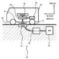
図1は本発明の実施の形態に係る無線給電システムの全体構成図である。この図に示す無線給電システムは、電磁誘導の相互作用を利用して電気自動車等の電動式移動体40に無線で電力を供給するものであり、地上側の充電施設(充電スタンド)50に設置された給電器51と、移動体40に搭載された受電器41を備えている。図1中に示した座標系の矢印は、電動式移動体40の長さ方向(直進方向)と鉛直方向を示している。なお、給電器51と受電器41を併せて無線給電装置と称することがある。また、ここでは、移動体40が大型の電気自動車の場合について説明するが、中型・小型の自動車、油圧ショベル及びホイールローダ等の建設機械、フォークリフト等の産業機械等、充電可能な蓄電装置を備えるものであればその他のものでも良い。 FIG. 1 is an overall configuration diagram of a wireless power feeding system according to an embodiment of the present invention. The wireless power feeding system shown in this figure supplies electric power wirelessly to an
給電器51は、地面60に対して相対移動不能に固定されており、インバータ装置(制御装置)52を介して電源53に接続されている。インバータ装置52及び電源53は充電施設50に設置されている。電源53としては例えば交流電源が利用可能である。給電器51には電気伝導性を有する線材(電線)を環状に巻いて形成した複数の一次コイル11,12(図2等参照)が収納されており、電源53からインバータ装置52を介して供給される高周波数の電流によって当該複数の給電コイルの周囲に磁界が発生される。なお、図1のインバータ装置52及び電源53は地中に埋設されているが、これらは地上に設置しても良い。 The
受電器41は、インバータ装置(制御装置)43を介して蓄電装置42に接続されている。インバータ装置43及び蓄電装置42は移動体40に搭載されている。蓄電装置42としては例えばリチウムイオン電池等の二次電池やキャパシタが利用可能である。受電器41には電気伝導性を有する線材(電線)を環状に巻いて形成した2次コイル13(図2等参照)が備えられている。 The
インバータ装置52は、電源53からの電流を、電動式移動体の充電に適した高周波数の交流電流に変換して給電器51に供給する。給電器51に高周波数の交流電流を供給すると、2次コイル13を貫く磁束(つまり、1次コイル11,12が発生する磁束)の変化の割合を増大できるので、2次コイル13に発生する誘導電流の電圧が上昇し、電動式移動体に適した大電力(1kW以上)での給電が可能となる。 The
給電器51から受電器41への給電に適した位置(例えば、受電器41と給電器51が対向配置する位置)に移動体40を移動させ、インバータ装置52で給電器51に交流電流を供給すると、給電器51で発生する磁界が変化して2次コイル13に電流(誘導電流)が流れ、蓄電装置42が充電される。蓄電装置42に蓄えられた電力は、インバータ装置43に接続されたモータ44等の電機に供給されて利用される。ここでは、移動体40の車輪を駆動するためのモータ44に蓄電装置42から電力を供給する場合について説明するが、蓄電装置42の電力供給対象は移動体40に搭載された他の電機としても良い。 The moving
なお、図1に示した受電器41は、移動体40の底面に設置されているが、移動体40に設置するのであれば他の場所(例えば、移動体40の側面や上面)に設置しても良い。その場合には、充電施設50での給電器51の設置場所が受電器41の設置場所に合わせて変更されることは言うまでもない。なお、図1中の給電器51は、その上面の高さが地表面以下になるように地面60に固定されている。 The
図2は本発明の第1の実施の形態に係る1次コイル11,12と2次コイル13の斜視図である。図中に示した座標系の矢印は、移動体40の「長さ方向」(直進方向)と、移動体の「車幅方向(幅方向)」と、「鉛直方向」を示している。なお、先の図と同じ部分には同じ符号を付して説明を省略することがある(後の図も同様とする)。 FIG. 2 is a perspective view of the
図2に示すように、給電器51には、1対(すなわち2つ)の1次コイル11,12と、板状のコア(一次側磁性体)31,32と、遮蔽板(一次側遮蔽部材)81が収納されている。受電器41には、1つの2次コイル13と、棒状のコア(二次側磁性体)33と、遮蔽板(二次側遮蔽部材)82が収納されている。 As shown in FIG. 2, the
給電器51において、板状コア31,32は、強磁性体(例えば、鉄、フェライト)から成り、1次コイル11,12の背面(各1次コイル11,12の軸方向に配置される2つ端面のうち2次コイル13から遠い面)にそれぞれ取り付けられている。なお、電力のロスを低減する観点からは、各板状コア31,32の長さ方向の長さは1次コイル11,12の長さ方向の内寸とし、各コア31,32の車幅方向の長さは1次コイル11,12の車幅方向の内寸とすることが好ましい。また、図2の例では、2枚のコア31,32の間隔を空けて配置したが、車幅方向の長さを延長する等して2枚のコア31,32の間隔を小さくする方が効率が良く、電力のロスを低減できる。例えば、2枚の板状コア31,32を連結して1枚の板部材とし、これを1対の1次コイル11,12の下面に配置しても良い。さらに、3枚以上の板状コアを組み合わせて1枚の板部材(板状コア)を形成しても良い。 In the
遮蔽板(一次側遮蔽部材)81は、通電中に給電器51の外部への漏洩磁束を遮蔽するためのもので、非磁性体(例えば、アルミニウム、銅)から成り、板状コア31,32の底面(2次コイル13から遠い方の面)に取り付けられている。図示した遮蔽板81は板状のものであるが、当該板の端部から立ち上がる壁面を設け、1次コイル11,12を外周から取り囲むようにしても良い。また、お椀形状など、曲面を利用しても良い。また、遮蔽板81は、給電器51内に収納する必要は無く、図示した配置では給電器51の底面に遮蔽板81を設置しても良い。さらに、図示した例では1対の1次コイル11,12で1つの遮蔽板81を共有したが、各1次コイル11,12に1つの遮蔽板を配置しても良い。 The shielding plate (primary side shielding member) 81 is for shielding leakage magnetic flux to the outside of the
受電器41において、棒状コア33は、強磁性体(例えば、鉄、フェライト)から成り、2次コイル13の環の内部に配置されている。 In the
遮蔽板(二次側遮蔽部材)82は、通電中に受電器41の外部への漏洩磁束を遮蔽するためのもので、非磁性体(例えば、アルミニウム、銅)から成り、2次コイル13の上方(1次コイル11,12から遠い方)に取り付けられている。なお、遮蔽板82についても、遮蔽板81と同様に、板の端部から立ち上がる壁面を設け、2次コイル13を外周から取り囲むようにしても良い。また、同様に曲面を利用しても良い。また、遮蔽板82は、受電器41内に収納する必要は無く、図示した配置では受電器41の上面に遮蔽板82を設置しても良い。すなわち、移動体40の底面に遮蔽板82を介して受電器41を取り付けてもよい。 The shielding plate (secondary shielding member) 82 is for shielding leakage magnetic flux to the outside of the
図2では図示を省略したが、給電器51における2つの1次コイル11,12はシリーズ結線(直列接続)されている(なお、他の図でも図示は省略するが、以下では、2つの1次コイル11,12はシリーズ結線されているものとする)。ここで1対の1次コイル11,12をシリーズ結線した場合の具体例について図3を用いて説明する。 Although not shown in FIG. 2, the two
図3は1対の1次コイル11,12をシリーズ結線した場合の一例を示す図である。この図の例では、各コイル11,12は1ターンずつ巻かれており、1本の電線のみで形成されている。2つのコイル11,12に通電したときに、当該2つのコイル11,12が形成する各環の全ての内側を通過しつつ当該各環の外側は通過しない環状の磁束を含むダイポール磁場が発生するように、2つのコイル11,12は巻かれている。図3の例では、鉛直方向において上から下に向かって2つの1次コイル11,12をみると、2つの1次コイル11,12の巻線方向は互いに反対になっている(1次コイル11は反時計回りの方向に、1次コイル12は時計回りの方向に電線が巻かれている。)。図3中の矢印の方向に電流を流すと(すなわち、コイル11に反時計回りの電流を流し、コイル12に時計回りの電流を流す)、図3中の点線で示した円状(楕円状)の閉曲線21を磁力線として有するダイポール磁場が発生する。2つの1次コイル11,12は、シリーズ結線されているため、常に同位相の交流電流が流れ、図示した円状の磁力線21を有するダイポール磁場を容易に発生することができる。 FIG. 3 is a diagram showing an example when a pair of
なお、図3では、2つの1次コイル11,12が発生するダイポール磁場を分かり易く表現するためにコア31,32の無い場合の磁場を表したが、図2の例ではコア31,32が存在する。そのため、図2の例では、図3〜図6に示した円形の磁力線21を中心軸に有する環状形状を、板状コア31,32で半分に切断したような形状(以下、「半環状」と称することがある)の磁場が形成される。すなわち、図2中に示した磁力線21を有するダイポール磁場が形成される。 In FIG. 3, in order to express the dipole magnetic field generated by the two
2つの1次コイル11,12と、2次コイル13について、他の図を用いてさらに説明する。図4は本発明の第1の実施の形態に係る1対の1次コイル11,12と2次コイル13のみを取り出して表した斜視図であり、図5はその正面図であり、図6はその側面図である。 The two
各コイル11,12,13は、電線を略矩形状に複数回巻き回して扁平に形成されている。各コイル11,12,13の電線又は全体は、絶縁体によって被覆することが好ましい。図に示した例では、2つの1次コイル11,12は互いに同じ形状である。一方、2次コイル13は、長辺方向は1次コイル11(12)と同じで、短辺方向は1次コイル11(12)の半分にしてある。ただし、このコイル11,12,13の形状は一例に過ぎない。すなわち、本実施の形態に係る各コイル11,12,13は、車幅方向の辺よりも長さ方向の辺が長い矩形状(長方形状)に形成されているが、各辺の長短を逆転させた矩形状、正方形状、円状、または楕円状等に形成しても良い。また同様に、各コイル11,12,13の形状を異ならせても良い。また、各コイル11,12,13に係る電線の材質としては、表皮効果による渦電流損を低減するため、リッツ線などが好適である。なお、電流密度の制限によっては、複数本の電線を並列に配置し、1次コイル11,12でシリーズ結線してもよい。 Each of the
2つの1次コイル11,12の中心軸A11,A12に直交する2つの面S11,S12の成す角(二面角)のうち、2次コイル13が配置される側の角度(以下、θと称する)は、180度となっている。図2〜6の例では、2つの1次コイル11,12は、車幅方向と長さ方向で規定される面上に位置しており、車幅方向に所定の間隔を介して配置されている。これにより、2つの1次コイルに係る中心軸A11,A12はともに略鉛直に保持されている。このように水平面上に1次コイル11,12を並列すると、給電器51が人や移動体等の往来の邪魔にならない。なお、2つの1次コイル11,12のなす角θは、当該2つのコイル11,12がダイポール磁場を形成しつつ、当該2つのコイル11,12の間に2次コイル13が配置可能であれば良く、図示した180度のみに限らない(詳細については後述する)。 Of the angles (dihedral angles) formed by the two surfaces S11, S12 orthogonal to the central axes A11, A12 of the two
また、各1次コイル11,12は、長辺が「長さ方向」に沿いつつ、短辺が「車幅方向」に沿うように配置されている。なお、車幅方向における2つの1次コイル11,12の間隔、すなわち両コイル11,12の中心点間距離(中心点C11から中心点C12までの距離)は、各コイル11,12の車幅方向の長さを半分にした値を足し併せた値より大きく設定されており、2つのコイル11,12が重ならないようになっている。なお、以下における「コイルの中心点」とは、当該コイルの中心軸のうち当該コイル内に含まれる部分に係る中点とする。 The primary coils 11 and 12 are arranged such that the long side is along the “length direction” and the short side is along the “vehicle width direction”. The distance between the two
ところで、給電器51から受電器41に給電可能な移動体40の停止範囲は、1対の1次コイル11,12が発生するダイポール磁場の磁束を2次コイル13に鎖交できる範囲に限られる。また、給電器51と受電器41の位置ずれが大きいと周囲への磁束漏洩が増大するおそれがあるので、磁束漏洩抑制の観点からも移動体40の停止範囲は予め設定することが好ましい。 By the way, the stop range of the moving
そこで、本実施の形態では、充電可能な移動体40の停止位置を明示する手段(充電位置指示手段)として、路面に凹部70(図1参照)を設けている。凹部70は、移動体40の後輪が収納可能な大きさに形成されており、図1の例では乗り越えの容易な凸部を前後に設けたものになっている。このように停止位置指示手段を設け、移動体40に係る左右の後輪が凹部70内に収納された状態で移動体40を停止すれば、少なくとも移動体40の長さ方向については充電に適した位置で移動体40を停止できる。すなわち、1次コイル11,12と受電側13の位置関係について、図6に示した状態は凹部70で担保できる。 Therefore, in the present embodiment, a recess 70 (see FIG. 1) is provided on the road surface as means for clearly indicating the stop position of the chargeable moving body 40 (charging position instruction means). The
なお、充電位置指示手段としては、凹部70に代えて、充電可能位置で移動体40の前輪が収納される凹部を利用しても良い。また、他の充電位置指示手段としては、移動体40の後輪に接触して停止位置を示す一般的な車止めを利用しても良いし、路面に施したペイント(例えば、停止線)で充電位置を運転者に明示する等しても良い。すなわち、充電位置を指示できるものであれば、その態様に特に限定はない。 In addition, as a charging position instruction | indication means, it may replace with the recessed
さらに、本実施の形態に係るインバータ装置52は、給電器51に対する受電器41の相対的な方向(向き)と水平方向距離を公知の検出器(例えば、加速度センサ、ジャイロセンサ、磁気センサ)で検出し、両者の方向と水平方向距離が所定の範囲に収まっている場合のみに1次コイル11,12への交流電流の通電を許可するように構成されている。このようにすると、漏洩磁束を低減することができる。なお、給電器51に対する受電器41の向き(方向)と水平距離を移動体40の運転者に報知して、停止位置の目安にしても良い。 Furthermore, the
次に2次コイル13について説明する。2次コイル13は、1次コイル11,12の通電時(すなわち、蓄電装置42への充電時)には、当該1次コイル11,12が発生する磁束21に鎖交するように配置される。また、2次コイル13の中心点C13は、当該2つの1次コイル11,12の中心点C11,点C12を通過する直線L上に位置せず、当該直線Lの周囲に位置している。 Next, the
また、2次コイル13の中心軸A13は、移動体40を移動させることで中心軸A13を直線Lと同一平面上に配置したとき、直線Lと平行になるように移動体40(受電器41)に固定されている。なお、図2〜6に示した状態では、蓄電装置42の充電に最も適した位置で移動体40を停止させた状態を示している。すなわち、移動体40の左右の後輪を凹部70内に収納した状態(移動体40の長さ方向に係る位置ずれの無い状態)であり、車幅方向において2つの1次コイル11,12の中心点C11,C12から等距離の位置に2次コイル13の中心点C13が位置しており、さらに中心軸A13は直線Lの鉛直上方に位置している。 In addition, when the center axis A13 of the
また、2つの1次コイル11,12の通電時における2次コイル13の中心軸A13の方向は、当該2つの1次コイル11,12に係る2つの中心軸A11,A12の方向と異なっている。すなわち、本実施の形態では、図5に示すように、2次コイル13の中心軸A13の方向は車幅方向に設定されているが、1次コイル11,12の中心軸A11,A12の方向は鉛直方向に設定されている。なお、本実施の形態では、2次コイル13の中心軸A13の方向は、2つの1次コイル11,12の中心軸A11,A12とそれぞれ異なっているが、中心軸A13の方向は、2つの1次コイル11,12の少なくとも一方の中心軸A11又はA12の方向と異なっていれば良い(すなわち、この場合の中心軸A13の方向は、2つの1次コイル11,12の中心軸A11,A12の一方に一致する。)。 The direction of the central axis A13 of the
ところで、本実施の形態に係る2次コイル13は、その中心軸A13が車幅方向と平行に保持されるように移動体40の底面に固定されている。これは、主として、2つの1次コイル11,12の配置方向(車幅方向)に中心軸A13の方向を一致させること(又は両者の方向をできるだけ近づけること)で、給電器51と受電器41の位置ずれに係る許容量を増大する観点と、受信側コイル13と鎖交する磁束を増加して充電効率を向上させる観点とに基づくものである。 By the way, the
また、2つの1次コイル11,12の中心点C11,C12を通過する直線Lから2次コイル13の中点C13までの距離(図2〜6の場合は、2次コイル13の地面からの設置高さ)は、電源53から1次コイル11,12に供給される電力量の大小や、1次コイル11,12が形成する磁界の特徴に応じて適宜調整することが好ましい。例えば、本実施の形態では、図3中の点Oから一方の1次コイル11の中心点C11までの距離を半径とし、中心をOとする円周上に主な磁界が形成されるものとして、当該円の半径程度の高さに中心軸A13を保持している。これにより、2つの1次コイル11,12に対して図2〜6が示すように2次コイル13を配置させれば、1次コイル11,12が発生する磁界の磁力線21が受信側コイル13の中心点C13で略垂直に鎖交する。 Further, the distance from the straight line L passing through the center points C11 and C12 of the two
上記のように構成される無線給電システムにおいて、給電器51から受電器41に無線給電を行う(すなわち、蓄電装置42の充電を行う)には、まず、運転者は充電位置指示手段(凹部70)に基づいて移動体40を充電に適した位置に停止させる。 In the wireless power feeding system configured as described above, in order to perform wireless power feeding from the
まず、1次コイル11,12の中間点Oの上方又はその近傍に2次コイル13の中心点C13が位置するように移動体40を停止できた場合には、1次コイル11,12と2次コイル13コイルの位置関係は図4〜6に示したものとなる。 First, when the moving
移動体40が停止され、給電器51に対して受電器41が所定の範囲内に収まっていることが確認できたら、インバータ装置52は、2つの1次コイル11,12に高周波の交流電流を通電して、給電器51から受電器41への給電を開始する。2つの1次コイル11,12はシリーズ結線されており常に同位相の電流が流れるため、各1次コイル11,12の電流の位相を特に調節等しなくても、1次コイル11,12の上方の空間に図2に示したような略半環状のダイポール磁場が発生する。このとき、2次コイル13は、2つの1次コイル11,12が形成するダイポール磁場の磁束に鎖交するように配置されているので、2次コイル13に誘導電流が発生して、蓄電装置42が充電される。 When it is confirmed that the moving
なお、図2の例では、1次コイル11,12の底面には強磁性体からなるコア31,32が設置されているため、1次コイル11,12による磁力線は、1次コイル11,12の下方ではコア31,32の内部を主に通過する。これにより、磁場の発生が受電器41側に限定されて、他の方向(例えば、コア31,32の下方)への磁束漏洩を抑制できる。 In the example of FIG. 2, since the
また、本実施の形態では、2次コイル13の中心軸A13は、直線Lと同一平面上に配置したとき、直線L(2つの1次コイル11,12の配置方向)と平行になるように固定されているため、図2の状態では、中心軸A13は、直線Lの鉛直上方に位置することになる。したがって、充電効率は他の場合と比較して顕著に高くなる。 Further, in the present embodiment, when the central axis A13 of the
ところで、移動体40の長さ方向の位置については凹部70をガイドにして充電位置に停止することができるが、車幅方向に係る給電器51と受電器41の位置ずれの程度の大小は運転者の技量や経験等に応じて異なる。その結果、上記の場合とは異なり、2次コイル13の中心点C13が点Oの上方又はその近傍に位置するように移動体40を停止できなかった場合には、車幅方向に給電器51と受電器41の位置ずれが生じることになる。 By the way, the position of the moving
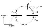
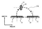
図7,8は、1次コイル11,12及び2次コイル13にコアが無い場合(図4,5,6の場合)において、1次コイル11,12と2次コイル13の位置ずれが車幅方向で生じた状態を示す図である。図7では2次コイル13が図中の左側にずれており、図8では図中の右側にずれている。一方、図9は、1次コイル11,12及び2次コイル13がコア31,32,33を備える場合(図2の場合)において、1次コイル11,12と2次コイル13の位置ずれが車幅方向で生じた状態を示す図である。 7 and 8 show that when the
図7,8のように1次コイル11,12及び2次コイル13にコアが無い場合にも、1次コイル11,12と2次コイル13の位置ずれが生じた場合には、2つの1次コイル11,12によって、給電器51と受電器41の間に位置する空間に略半環状に広がったダイポール磁場21を発生させることができるので、図4に示した最適な充電位置から2次コイル13の位置が車幅方向(2つの1次コイル11,12の配置方向)にずれても、2次コイル13での誘導電流の発生に有効な磁束21a,21bが存在する。これにより、車幅方向に位置ずれが生じても、図4〜6に示した場合よりも充電効率は相対的に低下するものの、問題無く充電できる。また、図5おける点Oからの車幅方向の位置ずれの許容量は、1次コイル11,12の中心間距離の半分程度までが目安となる。すなわち、点Oの位置から当該許容量程度ずれても、1次コイル11,12が発生する磁束と2次コイル13を鎖交させることができるので、蓄電装置42の充電を行うことができる。 7 and 8, even if the
図7,8を用いて説明した場合には、2次コイル13の位置ずれに付随して1次コイル11,12が発生する磁界自体には変化がなかったが、図2に示したように2次コイル13にコア33が存在する場合には、当該コア33に付随して磁界が変化する。図9のように2次コイル13の位置をずらすと、当該2次コイル13(コア33)の位置に付随して磁界21Aが変化し非対称になる。このように、2次コイル13をコアコイルとした場合には、空芯コイルとした場合(図7,8の場合)よりも当該コイルと鎖交する磁束を増加させることができるので、充電効率を向上させることができる。また、鎖交磁束が増加するので、1次コイル11,12の小型化も図ることができる。さらに、図2のように1次コイル11,12の背面に板状のコア31,32を設けると、図9に示したように外部に漏洩する磁場の発生を抑制することができるので、充電効率をさらに向上させることができる。 In the case described with reference to FIGS. 7 and 8, the magnetic field itself generated by the
なお、図7,8中に示した環状の磁束(磁力線)21a,21bは、1次コイル11,12によって形成される磁界に係る磁束21(図3等参照)のうち、位置ずれした2次コイル13における誘導電流の発生に有効な磁束21a,21bを示しているに過ぎず、1次コイル11,12によって形成される磁界に変化が生じる訳ではない。すなわち、図7,8の場合でも、1次コイル11,12は図3等に示した環状の磁界を発生している。 The annular magnetic flux (lines of magnetic force) 21a and 21b shown in FIGS. 7 and 8 are out-of-position secondary magnetic fluxes 21 (see FIG. 3 etc.) related to the magnetic field formed by the
次に、本実施の形態の効果についてまとめる。上記で説明したように、本実施の形態では、1対の1次コイル11,12を車幅方向に間隔を介して配置し、当該1対の1次コイル11,12に高周波数の電流を通電することで車幅方向に広がる略半環状のダイポール磁場を発生している(図2参照)。このように発生したダイポール磁場を発生すると、2つの1次コイル11,12の中心(中心点C11とC12の中点O(図5参照))から2次コイル13の中心点C13が車幅方向にずれても、1次コイル11,12の磁場が発生する磁束と2次コイル13を鎖交させることができるので、車幅方向における給電器51と受電器41の位置ずれの許容量を増大できる。 Next, the effects of the present embodiment will be summarized. As described above, in the present embodiment, a pair of
また、1対の1次コイル11,12によって発生するダイポール磁場は、1次コイルと2次コイルの中心軸を平行にした状態で給電する従来技術(特開2011−49230号公報)や、1次コイルと2次コイルを同軸上に配置した状態で給電する従来技術(例えば、特開2008−87733号公報)と比較して、1次コイル11,12の外周に漏洩する磁場を顕著に抑制できるので、大電力を利用した場合にも外部に与える磁場の影響を容易に抑制できる。 The dipole magnetic field generated by the pair of
ところで、携帯電話をはじめとする小型の携帯型電子装置の無線給電装置には、電源に対してパラレル結線(並列接続)された複数の1次コイルを備え、スイッチングなどで各1次コイルに通電される電流の位相を調節することで当該複数の1次コイルの周囲に磁場(ダイポール磁場を含む)を発生し、当該磁場に係る磁束に2次コイルを鎖交させることで当該2次コイルに誘導電流を発生する技術がある(国際公開第2009/027674号パンフレット)。しかし、携帯型電子装置のように小電力で足りる装置とは異なり、電動式移動体の充電には1kW以上の大電力が必要で、高周波数の電流を1次コイルに流す必要がある。そのため、パラレル結線された各1次コイルに高周波数の電流の位相を合わせることが難しく、携帯型電子装置用の無線給電装置を電動式移動体の充電に利用することは困難だった。 By the way, a wireless power feeding device of a small portable electronic device such as a cellular phone includes a plurality of primary coils connected in parallel (parallel connection) to a power source, and each primary coil is energized by switching or the like. By adjusting the phase of the generated current, a magnetic field (including a dipole magnetic field) is generated around the plurality of primary coils, and the secondary coil is linked to the magnetic flux related to the magnetic field. There is a technique for generating an induced current (International Publication No. 2009/027674 pamphlet). However, unlike a device that requires a small amount of power, such as a portable electronic device, charging an electric mobile body requires a large amount of power of 1 kW or more, and a high-frequency current needs to flow through the primary coil. For this reason, it is difficult to match the phase of a high-frequency current to each primary coil connected in parallel, and it is difficult to use a wireless power feeding device for a portable electronic device for charging an electric mobile body.
これに対して、本実施の形態に係る無線給電装置では、シリーズ結線された1対の1次コイル11,12を備え、当該1対の1次コイル11,12に高周波数の交流電流を流すこととした。このように1対の1次コイル11,12をシリーズ結線すると、各1次コイル11,12には常に同位相の電流が流れるため、各1次コイル11,12の電流の位相を特に調節等しなくても、1次コイル11,12の上方の空間に図2に示したような略半環状のダイポール磁場を発生できる。したがって、当該ダイポール磁場の磁束に2次コイル13を鎖交させれば、大電力が必要な電動式移動体の充電を容易に行うことができる。 In contrast, the wireless power feeding apparatus according to the present embodiment includes a pair of
したがって、上記のように構成した本実施の形態によれば、電動式移動体の無線給電装置において、1次コイル(給電器)と2次コイル(受電器)の位置ずれの許容量を容易に増大でき、さらに通電時の磁場漏洩も容易に抑制できる。 Therefore, according to the embodiment configured as described above, in the wireless power feeder of the electric mobile body, the allowable amount of positional deviation between the primary coil (power feeder) and the secondary coil (power receiver) can be easily achieved. Further, the leakage of the magnetic field during energization can be easily suppressed.
ところで、仮に、2つの1次コイル11,12の中心軸A11,A12が一致し、かつ、当該2つのコイル11,12の成す角θが0(すなわち、面S11と面S12が平行)であったとすると、2つの1次コイル11,12に挟まれた空間内に2次コイル13を配置しないと効果的な充電ができないことになる。そのため、当該2つの1次コイル11,12に対する2次コイル13の配置に制限が生じる。例えば、面S11と面S12が平行になるようにコイル11,12を鉛直方向に立てて配置した場合には、給電器51が地表に突出して障害物となる虞がある。すなわち、線的な移動のみを行う電車等の移動体の給電装置としては良いが、面的な移動も可能な移動体(例えば、自動車)の給電装置としては設置制限が大きくなり過ぎて不向きになることがある。 By the way, suppose that the central axes A11 and A12 of the two
これに対して、本実施の形態のように2つの1次コイル11,12を配置すると、当該2つのコイル11,12の間に環状の磁界の一部として曲線状の磁界が形成されるので、θが0の場合(2つのコイル11,12(2つの面S11,S12)が平行の場合)と比較して当該2つの1次コイル11,12から比較的離れた場所にも磁束を発生できるので、1次コイル11,12から離れた場所に2次コイル13を配置しても効果的な充電が可能になる。 In contrast, when the two
また、本実施の形態に係る2次コイル13は、中心軸A13が車幅方向と略平行になるように保持されており、2次コイル13が車幅方向(位置ずれの許容する方向に沿った寸法)に占める大きさは小さくて済むので、受電器41の車幅方向の寸法を小さくすることができる。また、これにより、遮蔽板81,82の面積も小さくできるので、移動体40への磁場漏洩も容易に抑制できる。 Further, the
ところで、上記の各実施の形態では、2つの1次コイル11,12の成す角θが180度の場合について説明したが、2つの1次コイル11,12によって環状の磁界21が形成できれば、θを180度以外の角度としても良い。強度の違いは生じるものの、理論上は、θが0より大きく360度未満であれば、環状の磁界の形成が可能である。 In each of the above embodiments, the case where the angle θ formed by the two
図10は本発明の第2の実施の形態に係る1次コイル11a,12aと2次コイル13の正面図である。この図に示す無線給電装置は、2つの1次コイル11a,12aを備えており、当該2つの1次コイル11a,12aの成す角θは0より大きく180度未満の値である160度に設定されている。このように1次コイル11a,12aを配置しても、環状の磁界21を発生させることができるので、上記の各実施の形態と同様の効果を奏することができる。特に、本実施の形態では、第1の実施の形態よりも2次コイル13に1次コイル11a,12aを近づけることができるため、充電効率を向上することができる。 FIG. 10 is a front view of the
ところで、上記の各実施の形態では、上記の各実施の形態では、2つの1次コイル11,12(11a,12a)を有する給電器51を備えた場合について説明したが、給電器51に係る複数の1次コイルに係る環の内部を全て通過する磁力線が描くことができる「環状の磁界」を形成することができれば、給電器51に備える1次コイル11,12の個数は3以上としてもよい。 By the way, in each said embodiment, although each said embodiment demonstrated the case where the
図11は本発明の第3の実施の形態に係る1次コイル11b,12b,14,15と2次コイル13の正面図である。この図に示す無線給電装置は、4つの1次コイル11b,12b,14,15を備えている。 FIG. 11 is a front view of the
4つの1次コイル11b,12b,14,15のうち、2次コイル13に鎖交させるための磁束の発生に影響を与えるのは、充電時の2次コイル13に隣りあって設置されている2つの2次コイル11b,12bである。そこで、本実施の形態のように1次コイルが3つ以上存在する場合の1次コイルの成す角θは、2次コイル13に隣り合う2つの1次コイル11b,12bを基準にする。図11の場合、2つの1次コイル11b,12bの成す角θは、180度より大きく360度未満の値である200度に設定されている。このように1次コイル11b,12bを配置しても、環状の磁界21を発生させることができる。 Of the four
1次コイル14は、2つの1次コイル11b,12bが発生する環状の磁界21上であって、1次コイル11bの下方にこれと近接して設置されている。2つの1次コイル11b,12bが発生する環状の磁界21上であって、1次コイル15は、1次コイル12bの下方にこれと近接して設置されている。このように相対的に下方に位置するコイル14,15を、相対的に上方に位置するコイル11b,12bに近接させると、2つのコイル11b,12bの成す角θが第1の実施形態等よりも大きくなった場合にも、2次コイル13の鎖交磁束の低下を抑制することができる。 The
したがって、上記のように構成した本実施の形態によっても、複数の1次コイル11b,12b,14,15によって環状の磁界を形成することができ、給電器51と受電器41の位置ずれの許容量を容易に増大できる。 Therefore, also in the present embodiment configured as described above, an annular magnetic field can be formed by the plurality of
次の本発明の第4の実施の形態について説明する。図12は本発明の第4の実施の形態に係るモールドコイル100の斜視図であり、図13はその断面図である。 Next, a fourth embodiment of the present invention will be described. FIG. 12 is a perspective view of a molded
図12,13に示したモールドコイル100は、耐候性に優れた樹脂120によって略直方体状に成形(モールド)されたものであり、給電器51内に備えられている。モールドコイル100は、樹脂120内に封入された1次コイル11,12及びコア31,32と、1次コイル11,12及びコア31,32とともに樹脂120内に封入された第1伝導体250と、樹脂120内から外部に露出した第2伝導体140と、第2伝導体140における外側の端部に接続された放熱体150を備えている。1対の1次コイル11,12は図3に示したものと同様にシリーズ結線110(図13参照)されている。 The molded
モールドコイル100に用いる樹脂120としては、例えば、不飽和ポリエステル樹脂、エポキシ樹脂、フッ素樹脂、ABS樹脂、アクリル樹脂、ポリエチレン、ポリプロピレンがある。なお、モールドコイルを他の材料で成形し、その表面に、フッ素系塗料、アクリル、アクリルウレタン等の耐候性に優れた塗料を塗布しても良い。もちろん、これらの塗料を耐候性に優れた樹脂に塗布しても良い。 Examples of the
第1伝導体250は、熱及び電気の良伝導体であり、板状に形成されている。図に示した例では排熱効果を促進する観点に基づいて、第1伝導体250はコア31,32の下面に接触させているが、コア31,32と離して固定しても良い。また、第1伝導体250としては、樹脂120よりも熱伝導率の大きい伝導体が利用されており、例えば、銅、アルミニウムなどの金属を利用することが好ましい。さらに、第1伝導体250は、誘導電流に起因した渦電流の発生を抑制する観点から非磁性体であることが好ましく、当該観点からはアルミニウムが特に好適となる。 The
第2伝導体140は、熱及び電気の良伝導体であり、第1伝導体250と樹脂120の内部で接触しており、樹脂120の外部に露出している。本実施の形態の第2伝導体140は、線状の伝導体であり、その一端は樹脂120の内部で第1伝導体250の底面と結合しており、その他端は樹脂120の外部で放熱体150に接続されている。第2伝導体140としては、樹脂120よりも熱伝導率の大きい伝導体を利用するものとし、例えば、金属が好ましい。また、その利用の性質上、電導性よりも伝熱性が重要となる。さらに、第2伝導体140の他端が外部に露出する関係上、過酷な環境下での使用が想定されるので、ステンレス等の耐候性に優れた金属を用いることが好ましい。 The
放熱体150は、コア31,32及び第1伝導体250から第2伝導140を介して伝達してくる熱の放出を促進するためのものである。図に示した放熱体150は、直方体における左右の側面に所定の間隔で配列された複数のフィンを備えることで表面積を増加させ、これにより放熱効果の向上を図っている。放熱体150の材料は、熱伝導率が高く耐候性に優れたものが好ましく、例えば、耐食性に優れたアルミニウム合金で形成しても良い。放熱体150は、大気中に固定しても良いし、地中に埋設する等しても良く、後者の場合には前者の場合よりも放熱効果が向上する。 The
なお、放熱体150は、図示した形状に限らず、放熱に適したものであれば他の形状でも良い。また、放熱体150の内部に冷却水流路を形成する等して、放熱体150を水冷式の冷却装置としても良い。さらに、本実施の形態では、第2伝導体140に放熱体150を取り付けた例について説明したが、第2伝導体140が外部に露出していればある程度の放熱機能は担保されるので、放熱体150は省略しても良い。 In addition, the
ところで、無線給電装置における給電器は、給電器(1次コイル)は、屋外に設置され、温湿度変化、粉塵及び風雨等にさらされる過酷な環境で利用されることが想定される。そのため、金属(電線)から成る1次コイルは、耐候性に優れた樹脂等の材料でモールド成形し、外界との接触を遮断することが好ましい。樹脂でモールドしたコイルに交流電流を通電すると、コイルの温度が上昇する。このように加熱されたコイルは、モールド樹脂を介した外部への熱の拡散によってある程度冷却されることになる。 By the way, as for the power feeder in a wireless power feeder, the power feeder (primary coil) is assumed to be installed outdoors and used in a harsh environment exposed to changes in temperature and humidity, dust, wind and rain, and the like. Therefore, it is preferable that the primary coil made of metal (electric wire) is molded with a material such as a resin having excellent weather resistance to block contact with the outside. When an alternating current is passed through a coil molded with resin, the temperature of the coil rises. The coil heated in this way is cooled to some extent by the diffusion of heat to the outside through the mold resin.
しかし、コイルの発熱は、交流電流の通電時間(すなわち、充電時間)や、その周波数に比例して増大する。そして、樹脂は金属に比べて熱伝導率が低いため、通電時間や周波数によってはコイルの冷却が不充分になるおそれがある。さらに、コイルに加熱された樹脂が損傷するおそれもある。このような事態を回避するための方策として、例えば、コイルへの通電時間に制限を設けることが考えられるが、複数の電動移動体の充電が継続的に実施されることが前提となる充電施設の給電器としては、充電時間に制限が設定されることは好ましくない。複数の給電器を交代で使用するシステムの構築も考えられるが、充電施設のイニシャルコストが増大する点で好ましくない。なお、ここでは、充電施設で発生する課題を想定したが、給電器から受電器への給電が継続的に行われるシステムであれば同様の課題が生じることは言うまでもない。 However, the heat generation of the coil increases in proportion to the energization time of the alternating current (that is, the charging time) and its frequency. Since the resin has a lower thermal conductivity than the metal, the coil may be insufficiently cooled depending on the energization time and frequency. Further, the resin heated by the coil may be damaged. As a measure for avoiding such a situation, for example, it is conceivable to limit the energization time to the coil, but a charging facility on the premise that charging of a plurality of electric mobile bodies is continuously performed It is not preferable that a limit is set for the charging time of the power feeder. Although it is conceivable to construct a system that uses a plurality of power feeders alternately, it is not preferable in that the initial cost of the charging facility increases. In addition, although the problem which generate | occur | produces in a charging facility was assumed here, it cannot be overemphasized that the same problem will arise if it is a system with which electric power feeding from a power feeder to a power receiver is performed continuously.
本願発明者らは、上記の課題を鑑みて図12,13に示したモールドコイル100に想到した。上記のように構成されるモールドコイル100を備えた給電器51によれば、電動式移動体の充電に適した高周波数の交流電流を1次コイル11,12へ通電する時間が長期化して顕著な発熱があった場合にも、1次コイル11,12で発生した熱をコア31,32及び第1伝導体250から第2伝導体140を介してモールドコイル100の外部に放出することができる。これにより樹脂120の加熱が抑制されるので、連続した通電、すなわち受電器41に対して継続した給電を実施することができる。また、第1伝導体250は、モールドコイル100の剛性向上に寄与するとともに、1次コイル11,12の取り付け位置の基準となるので製造工程が容易になる。 The present inventors have conceived the molded
第4の実施の形態では、1対の1次コイル11,12を一体にしてモールドしたが、これらは個別にモールドしても良い。図14は本発明の第5の実施の形態に係るモールドコイル101、102の断面図である。 In the fourth embodiment, the pair of
この図において、モールドコイル101は、樹脂120内に封入された1次コイル11及びコア31と、第1伝導体250と、第2伝導体140と、放熱体150を備えており、モールドコイル102は、樹脂120内に封入された1次コイル12及びコア32と、第1伝導体250と、第2伝導体140と、放熱体150を備えている。2つのモールドコイル101、102は、各樹脂120,120内の1対の1次コイル11,12をシリーズ結線するためのケーブル115を介して接続されている。 In this figure, a molded
ケーブル115は、コイル11,12とともに樹脂120内に封入して一体式にしても良いし、2つのモールドコイル101,102の表面にコイル11,12に接続される取り付け口をそれぞれ設け、当該取り付け口を介して1対の1次コイルを結線する着脱式のものにしても良い。 The
本実施の形態のようにモールドコイル101,102を構成すると、充電施設の仕様に合わせて1次コイル11,12を容易にレイアウトできる。なお、上記の説明では、給電器51内の1次コイル11,12をモールドする場合について説明したが、受電器41内の2次コイル13も同様にモールドしても良い。 When the molded
なお、上記の各実施の形態では、充電施設50に設置した凹部(充電位置指示手段)70との関係上、2つの1次コイル11,12を車幅方向に配置して給電器51を構成する場合について説明したが、その他の方向(例えば、移動体40の長さ方向)に2つの1次コイル11,12を配置して給電器51を構成しても良い。この場合には、当該2つの1次コイル11,13を配設した方向が、位置ずれを許容する主な方向となる。 In each of the above-described embodiments, the
また、図1に示した受電器41は、給電器51が埋設された地面60に対向するように移動体40の底面に設置されているが、給電器51に対向配置されれば良く、給電器51の設置位置に応じて他の場所に設置しても良い。例えば、給電器51が移動体40の側面に設置される場合には、当該給電器51に対向するように移動体40の側面に設置すれば良いし、給電器51が移動体40の上方に設置される場合には、移動体40の上面に設置すれば良い。また、図1に示した給電器51は、地面(路面)60に埋設されているが、既述のように受電器41と対向配置されれば他の場所に設置しても良い。 Further, the
さらに、上記の各実施の形態における複数の1次コイルの配置は、これによって形成された環状の磁界の主な磁力線が、所定の直線に対して線対称の閉曲線(楕円や円等)で描けるものであった。しかし、このような磁力線が描けるものに限られず、各1次コイルの内部(環の内側)をすべて通過する磁力線が閉曲線で描けるものであれば、他の配置をしても本発明は適用可能である。 Furthermore, the arrangement of the plurality of primary coils in each of the above embodiments allows the main magnetic lines of force of the annular magnetic field formed thereby to be drawn by a closed curve (ellipse, circle, etc.) that is axisymmetric with respect to a predetermined straight line. It was a thing. However, the present invention is not limited to those that can draw such magnetic field lines, and the present invention can be applied to other arrangements as long as the magnetic field lines that pass through all of the primary coils (inside the ring) can be drawn in a closed curve. It is.
例えば、所定の面上に位置する所定の閉曲線上の異なる位置に、複数の1次コイルの中心点が位置するように配置しつつ、さらに当該閉曲線上において各1次コイルの中心軸と当該閉曲線が接するように配置するものがある。このように閉曲線上に配置した各1次コイルに対して、当該閉曲線が各1次コイルの環を貫く方向を基準として当該各1次コイルに同じ方向に電流を流すと、当該閉曲線に概ね沿った磁力線を有する磁界が形成され、当該磁界は当該各1次コイルが電線で形成する複数の環の全ての内側を通過する環状のものとなる。 For example, while arranging so that the center points of a plurality of primary coils are located at different positions on a predetermined closed curve located on a predetermined surface, the central axis of each primary coil and the closed curve on the closed curve Some are placed so that they touch each other. For each primary coil arranged on the closed curve in this way, when current flows in the same direction in each primary coil with reference to the direction in which the closed curve passes through the ring of each primary coil, the current substantially follows the closed curve. A magnetic field having a line of magnetic force is formed, and the magnetic field is an annular one that passes through all the insides of the plurality of rings formed by the primary coils.
なお、本発明は、上記で説明した各実施の形態に限定されるものではなく、その要旨を逸脱しない範囲内の様々な変形例が含まれる。例えば、本発明は、上記の実施の形態で説明した全ての構成を備えるものに限定されず、その構成の一部を削除したものも含まれる。また、ある実施の形態に係る構成の一部を、他の実施の形態に係る構成に追加又は置換することが可能である。 In addition, this invention is not limited to each embodiment demonstrated above, The various modification within the range which does not deviate from the summary is contained. For example, the present invention is not limited to the one having all the configurations described in the above embodiment, and includes a configuration in which a part of the configuration is deleted. In addition, part of the configuration according to one embodiment can be added to or replaced with the configuration according to another embodiment.
11,12…1次コイル、13…2次コイル、14,15…1次コイル、21…磁界(磁力線)、31,32,33…磁性体(コア)、40…移動体(電気自動車)、41…受電器、42…蓄電装置、43…インバータ装置、44…モータ、50…充電施設、51…給電器、52…インバータ装置、53…電源、60…地面、70…凹部(充電位置指示手段)、81,82…遮蔽板、100,101,102…モールドコイル、120…樹脂、140…第2伝導体、150…放熱体、250…第1伝導体 11, 12 ... primary coil, 13 ... secondary coil, 14, 15 ... primary coil, 21 ... magnetic field (lines of magnetic force), 31, 32, 33 ... magnetic body (core), 40 ... moving body (electric vehicle), DESCRIPTION OF
本発明は、上記目的を達成するために、シリーズ結線され、通電時にダイポール磁場を発生する一対の一次コイルと、当該一対の一次コイルの通電時に当該一対の一次コイルが発生する磁束に鎖交可能に電動式移動体に搭載された二次コイルと、前記一対の一次コイルと前記二次コイルとの水平方向距離が所定の範囲に収まっているときにのみ前記一対の一次コイルへの交流電流の通電を許可する制御装置と、前記一対の一次コイルのそれぞれにおける2つの端面のうち前記二次コイルから遠い面の方にそれぞれ配置された板状の一次側磁性体と、前記二次コイルの内部に配置された二次側磁性体と、前記一対の一次コイルのそれぞれにおける2つの端面のうち前記二次コイルから遠い面の方にそれぞれ配置され、漏洩磁束を遮蔽する一次側遮蔽部材と、前記二次コイルと前記電動式移動体の間に位置するように前記電動式移動体に取り付けられ、漏洩磁束を遮蔽する二次側遮蔽部材とを備えるものとする。In order to achieve the above object, the present invention can be linked to a pair of primary coils that are connected in series and generate a dipole magnetic field when energized, and a magnetic flux generated by the pair of primary coils when energized to the pair of primary coils.Only when a horizontal distance between the secondary coil mounted on the electric mobile body andthe pair of primary coils and the secondary coil is within a predetermined range. A control device that permits energization, a plate-like primary side magnetic body that is disposed on a surface far from the secondary coil among the two end faces of each of the pair of primary coils, and the interior of the secondary coil The primary side that shields the leakage magnetic flux and is arranged on the side farther from the secondary coil among the two end faces of the secondary side magnetic body arranged on each of the pair of primary coils. And蔽部material, wherein attached to the electric moving body so as to be positioned between said secondary coil and said electric moving body, it is assumed that anda secondary-side shielding member for shielding a leakage magnetic flux.
Claims (11)
Translated fromJapanese当該一対の一次コイルの通電時に当該一対の一次コイルが発生する磁束に鎖交可能に電動式移動体に搭載された二次コイルとを備えることを特徴とする電動式移動体の無線給電装置。A pair of primary coils connected in series and generating a dipole magnetic field when energized,
A wireless power feeding apparatus for an electric mobile body, comprising: a secondary coil mounted on the electric mobile body so as to be capable of interlinking with a magnetic flux generated by the pair of primary coils when the pair of primary coils is energized.
前記一対の一次コイルと前記二次コイルとの水平方向距離が所定の範囲に収まっているときにのみ前記一対の一次コイルへの交流電流の通電を許可する制御装置をさらに備えることを特徴とする電動式移動体の無線給電装置。The wireless power feeder of the electric mobile body according to claim 1,
The apparatus further includes a control device that permits energization of an alternating current to the pair of primary coils only when a horizontal distance between the pair of primary coils and the secondary coil is within a predetermined range. A wireless power feeder for an electric mobile body.
前記二次コイルの内部に配置された二次側磁性体をさらに備えることを特徴とする電動式移動体の無線給電装置。The wireless power feeder of the electric mobile body according to claim 1,
The wireless power feeder for an electric mobile body, further comprising a secondary side magnetic body disposed inside the secondary coil.
前記一対の一次コイルのそれぞれにおける2つの端面のうち前記二次コイルから遠い面の方にそれぞれ配置された板状の一次側磁性体をさらに備えることを特徴とする無線給電装置。The wireless power feeder of the electric mobile body according to claim 1,
A wireless power feeding apparatus, further comprising: a plate-like primary side magnetic body disposed on a surface far from the secondary coil among two end faces of each of the pair of primary coils.
前記一対の一次コイルは、当該一対の一次コイルに係る中心軸がともに略鉛直に保持されるように配置されており、
前記一次側磁性体は、1枚の板部材、または複数枚の部材を組み合わせて形成された板部材であり、前記一対の一次コイルの下方に配置されていることを特徴とする無線給電装置。The wireless power feeder of the electric mobile body according to claim 1,
The pair of primary coils are arranged such that the central axes of the pair of primary coils are both held substantially vertically,
The wireless power feeding device according to claim 1, wherein the primary side magnetic body is a plate member formed by combining a single plate member or a plurality of members, and is disposed below the pair of primary coils.
前記二次コイルは、漏洩磁束を遮蔽する遮蔽部材を介して前記電動式移動体に取り付けられていることを特徴とする電動式移動体の無線給電装置。The wireless power feeder of the electric mobile body according to claim 1,
The wireless power feeding device for an electric mobile body, wherein the secondary coil is attached to the electric mobile body via a shielding member that shields leakage magnetic flux.
前記一対の一次コイルのそれぞれにおける2つの端面のうち前記二次コイルから遠い面の方にそれぞれ配置され、漏洩磁束を遮蔽する遮蔽部材をさらに備えることを特徴とする電動式移動体の無線給電装置。The wireless power feeder of the electric mobile body according to claim 1,
A wireless power feeding device for an electric mobile body, further comprising a shielding member that is disposed on a surface far from the secondary coil among two end faces of each of the pair of primary coils, and shields leakage magnetic flux. .
前記一対の一次コイルが封入された樹脂と、
前記一対の一次コイルとともに前記樹脂内に封入され、前記樹脂よりも熱伝導率の大きい第1伝導体と、
当該第1伝導体と前記樹脂内部で接触し、前記樹脂の外部に露出した第2伝導体とをさらに備えることを特徴とする電動式移動体の無線給電装置。The wireless power feeder of the electric mobile body according to claim 1,
A resin encapsulating the pair of primary coils;
A first conductor encapsulated in the resin together with the pair of primary coils and having a higher thermal conductivity than the resin;
A wireless power feeder for an electric mobile body, further comprising a second conductor that contacts the first conductor and the resin and is exposed to the outside of the resin.
前記樹脂の外部で前記第2伝導体に取り付けられた放熱体をさらに備えることを特徴とする電動式移動体の無線給電装置。In the wireless power feeder of the electric mobile body according to claim 8,
A wireless power feeder for an electric mobile body, further comprising a heat dissipator attached to the second conductor outside the resin.
前記二次コイルは、その中心軸が前記電動式移動体の幅方向に配置されるように当該電動式移動体に固定されていることを特徴とする電動式移動体の無線給電装置。The wireless power feeder of the electric mobile body according to claim 1,
The wireless power feeding device for an electric mobile body, wherein the secondary coil is fixed to the electric mobile body so that a central axis thereof is arranged in a width direction of the electric mobile body.
前記一対の一次コイルの通電時に当該一対の一次コイルが発生する磁束に鎖交するように配置された二次コイルを有し、電動式移動体に搭載された受電器と、
前記一対の一次コイルに通電する交流電流を制御する制御装置とを備え、
前記二次コイルの中心軸は、前記電動式移動体の幅方向に保持されており、
前記一対の一次コイルの中心を通過する直線と前記二次コイルの中心軸が同一平面上に位置するように前記電動式移動体を移動させたとき、前記直線は前記二次コイルの中心軸に平行であり、
前記制御装置は、前記一対の一次コイルと前記二次コイルとの水平方向距離が所定の範囲に収まっているときにのみ前記一対の一次コイルへの交流電流の通電を許可することを特徴とする無線給電システム。A power supply fixed to the ground, having a pair of primary coils that are connected in series and generate a dipole magnetic field when energized,
A power receiver having a secondary coil arranged to interlink with a magnetic flux generated by the pair of primary coils when the pair of primary coils is energized, and mounted on an electric mobile body;
A controller for controlling an alternating current to be passed through the pair of primary coils,
The central axis of the secondary coil is held in the width direction of the electric mobile body,
When the electric movable body is moved so that the straight line passing through the center of the pair of primary coils and the central axis of the secondary coil are located on the same plane, the straight line is aligned with the central axis of the secondary coil. Parallel,
The control device permits energization of an alternating current to the pair of primary coils only when a horizontal distance between the pair of primary coils and the secondary coil is within a predetermined range. Wireless power supply system.
Priority Applications (3)
| Application Number | Priority Date | Filing Date | Title |
|---|---|---|---|
| JP2012286526AJP5286445B1 (en) | 2012-12-28 | 2012-12-28 | Wireless power feeder for electric mobile body |
| US14/138,867US20140183966A1 (en) | 2012-12-28 | 2013-12-23 | Inductive Power Supply System for Electric Operation Machine |
| EP13199392.5AEP2749445A1 (en) | 2012-12-28 | 2013-12-23 | Inductive power supply system for electric operation machine |
Applications Claiming Priority (1)
| Application Number | Priority Date | Filing Date | Title |
|---|---|---|---|
| JP2012286526AJP5286445B1 (en) | 2012-12-28 | 2012-12-28 | Wireless power feeder for electric mobile body |
Publications (2)
| Publication Number | Publication Date |
|---|---|
| JP5286445B1 JP5286445B1 (en) | 2013-09-11 |
| JP2014131370Atrue JP2014131370A (en) | 2014-07-10 |
Family
ID=49274072
Family Applications (1)
| Application Number | Title | Priority Date | Filing Date |
|---|---|---|---|
| JP2012286526AExpired - Fee RelatedJP5286445B1 (en) | 2012-12-28 | 2012-12-28 | Wireless power feeder for electric mobile body |
Country Status (3)
| Country | Link |
|---|---|
| US (1) | US20140183966A1 (en) |
| EP (1) | EP2749445A1 (en) |
| JP (1) | JP5286445B1 (en) |
Cited By (6)
| Publication number | Priority date | Publication date | Assignee | Title |
|---|---|---|---|---|
| KR20160057577A (en)* | 2014-11-13 | 2016-05-24 | 현대자동차주식회사 | Wireless charging system |
| JP2017108481A (en)* | 2015-12-07 | 2017-06-15 | ラピスセミコンダクタ株式会社 | Power transmission equipment and power transmission system |
| JP2017137701A (en)* | 2016-02-04 | 2017-08-10 | 矢崎総業株式会社 | Car stop, coil unit and power supply system having them |
| KR20170139220A (en)* | 2016-06-08 | 2017-12-19 | 한국과학기술원 | Wireless Power Transfer Apparatus |
| JP2023058936A (en)* | 2021-10-14 | 2023-04-26 | Nittoku株式会社 | Contactless power supply system |
| JP2023163926A (en)* | 2022-04-28 | 2023-11-10 | 株式会社Soken | Non-contact power transmission system |
Families Citing this family (19)
| Publication number | Priority date | Publication date | Assignee | Title |
|---|---|---|---|---|
| KR101697418B1 (en)* | 2012-05-09 | 2017-01-17 | 도요타지도샤가부시키가이샤 | Vehicle |
| JP5688549B2 (en) | 2013-04-10 | 2015-03-25 | パナソニック インテレクチュアル プロパティ コーポレーション オブアメリカPanasonic Intellectual Property Corporation of America | Coil module and electronic device |
| US10186912B2 (en)* | 2013-09-13 | 2019-01-22 | Qualcomm Incorporated | Pickup coil design for tight spaces and asymmetrical coupling |
| US10040360B1 (en)* | 2013-11-14 | 2018-08-07 | Momentum Dynamics Corporation | Method and apparatus for the alignment of vehicles prior to wireless charging including a transmission line that leaks a signal for alignment |
| US11241970B2 (en) | 2013-11-14 | 2022-02-08 | Momentum Dynamics Corporation | Method and apparatus for the alignment of vehicles prior to wireless charging |
| US10814729B2 (en) | 2013-11-14 | 2020-10-27 | Momentum Dynamics Corporation | Method and apparatus for the alignment of a vehicle and charging coil prior to wireless charging |
| US9831685B2 (en) | 2014-05-16 | 2017-11-28 | Samsung Electro-Mechanics Co., Ltd. | Wireless power transmitter |
| DE102014215299A1 (en)* | 2014-08-04 | 2016-02-04 | Robert Bosch Gmbh | Method for the contactless charging or discharging of a battery-powered object |
| KR102237776B1 (en)* | 2014-10-07 | 2021-04-09 | 삼성전자주식회사 | Wireless power transmission device |
| DE102014017544A1 (en)* | 2014-11-28 | 2016-06-02 | Sew-Eurodrive Gmbh & Co Kg | Method and system for inductive transmission of electrical energy to a vehicle |
| DE102015006307B4 (en) | 2015-05-16 | 2021-03-18 | Audi Ag | Charging device for inductive charging of an electrical energy store of a motor vehicle and method for operating a charging device |
| CN205141843U (en)* | 2015-10-26 | 2016-04-06 | 泰科电子(上海)有限公司 | Wireless power transmission device and electrical equipment |
| US11376966B2 (en) | 2016-07-19 | 2022-07-05 | Auckland Uniservices Limited | Electric vehicle detection for roadway wireless power transfer |
| US10501298B2 (en) | 2017-04-04 | 2019-12-10 | Tyri International, Inc. | Linear actuator system for moving tines of a work vehicle |
| US11283295B2 (en) | 2017-05-26 | 2022-03-22 | Nucurrent, Inc. | Device orientation independent wireless transmission system |
| CN107370243B (en)* | 2017-06-20 | 2019-06-07 | 华为技术有限公司 | A kind of terminal wireless charging receiver, emitter and wireless charging system |
| CN111009384B (en)* | 2019-11-21 | 2021-09-10 | 国电南瑞科技股份有限公司 | Layered tool structure of magnetic coupling resonant wireless power transmission device |
| US11283303B2 (en) | 2020-07-24 | 2022-03-22 | Nucurrent, Inc. | Area-apportioned wireless power antenna for maximized charging volume |
| US11695302B2 (en) | 2021-02-01 | 2023-07-04 | Nucurrent, Inc. | Segmented shielding for wide area wireless power transmitter |
Citations (12)
| Publication number | Priority date | Publication date | Assignee | Title |
|---|---|---|---|---|
| JPS6423728A (en)* | 1987-07-15 | 1989-01-26 | Seiko Epson Corp | Recharger for electronic clock |
| WO2005083879A1 (en)* | 2004-03-02 | 2005-09-09 | Seiko Epson Corporation | Motor and drive system of motor |
| JP2006523363A (en)* | 2003-02-04 | 2006-10-12 | アクセス ビジネス グループ インターナショナル リミテッド ライアビリティ カンパニー | Inductively powered device |
| JP2008087733A (en)* | 2006-10-05 | 2008-04-17 | Showa Aircraft Ind Co Ltd | Noncontact power supply device |
| JP2008109839A (en)* | 2006-09-29 | 2008-05-08 | Central Res Inst Of Electric Power Ind | Contactless power transmission system for moving objects |
| US20080298100A1 (en)* | 2007-06-01 | 2008-12-04 | Sanyo Electric Co., Ltd. | Contactless power receiving unit and electronic device employing the same |
| JP2010172084A (en)* | 2009-01-21 | 2010-08-05 | Saitama Univ | Non-contact power feeding device |
| JP2010538596A (en)* | 2007-08-28 | 2010-12-09 | アクセス ビジネス グループ インターナショナル リミテッド ライアビリティ カンパニー | Inductive power supply device |
| WO2011016736A2 (en)* | 2009-08-07 | 2011-02-10 | Auckland Uniservices Limited | Roadway powered electric vehicle system |
| WO2011077488A1 (en)* | 2009-12-24 | 2011-06-30 | 株式会社 東芝 | Wireless power transmission apparatus |
| WO2011077493A1 (en)* | 2009-12-25 | 2011-06-30 | 株式会社 東芝 | Wireless power transmission device and power receiving device |
| JP2012120411A (en)* | 2010-12-03 | 2012-06-21 | Fujitsu Ten Ltd | Power reception device, power transmission device, and wireless power transmission system |
Family Cites Families (4)
| Publication number | Priority date | Publication date | Assignee | Title |
|---|---|---|---|---|
| JP5354539B2 (en) | 2009-08-25 | 2013-11-27 | 国立大学法人埼玉大学 | Non-contact power feeding device |
| JP5899446B2 (en)* | 2010-09-21 | 2016-04-06 | パナソニックIpマネジメント株式会社 | Contactless power supply |
| EP2524834A1 (en)* | 2011-05-18 | 2012-11-21 | Brusa Elektronik AG | Device for inductive charging of at least one electrical energy storage device of an electric car |
| EP2848453B1 (en)* | 2012-05-09 | 2017-10-11 | Toyota Jidosha Kabushiki Kaisha | Vehicle comprising power reception coil |
- 2012
- 2012-12-28JPJP2012286526Apatent/JP5286445B1/ennot_activeExpired - Fee Related
- 2013
- 2013-12-23USUS14/138,867patent/US20140183966A1/ennot_activeAbandoned
- 2013-12-23EPEP13199392.5Apatent/EP2749445A1/ennot_activeWithdrawn
Patent Citations (13)
| Publication number | Priority date | Publication date | Assignee | Title |
|---|---|---|---|---|
| JPS6423728A (en)* | 1987-07-15 | 1989-01-26 | Seiko Epson Corp | Recharger for electronic clock |
| JP2006523363A (en)* | 2003-02-04 | 2006-10-12 | アクセス ビジネス グループ インターナショナル リミテッド ライアビリティ カンパニー | Inductively powered device |
| WO2005083879A1 (en)* | 2004-03-02 | 2005-09-09 | Seiko Epson Corporation | Motor and drive system of motor |
| JP2008109839A (en)* | 2006-09-29 | 2008-05-08 | Central Res Inst Of Electric Power Ind | Contactless power transmission system for moving objects |
| JP2008087733A (en)* | 2006-10-05 | 2008-04-17 | Showa Aircraft Ind Co Ltd | Noncontact power supply device |
| US20080298100A1 (en)* | 2007-06-01 | 2008-12-04 | Sanyo Electric Co., Ltd. | Contactless power receiving unit and electronic device employing the same |
| JP2010538596A (en)* | 2007-08-28 | 2010-12-09 | アクセス ビジネス グループ インターナショナル リミテッド ライアビリティ カンパニー | Inductive power supply device |
| JP2010172084A (en)* | 2009-01-21 | 2010-08-05 | Saitama Univ | Non-contact power feeding device |
| WO2011016736A2 (en)* | 2009-08-07 | 2011-02-10 | Auckland Uniservices Limited | Roadway powered electric vehicle system |
| JP2013501665A (en)* | 2009-08-07 | 2013-01-17 | オークランド ユニサービシズ リミテッド | Electric vehicle system that obtains electric energy from the road |
| WO2011077488A1 (en)* | 2009-12-24 | 2011-06-30 | 株式会社 東芝 | Wireless power transmission apparatus |
| WO2011077493A1 (en)* | 2009-12-25 | 2011-06-30 | 株式会社 東芝 | Wireless power transmission device and power receiving device |
| JP2012120411A (en)* | 2010-12-03 | 2012-06-21 | Fujitsu Ten Ltd | Power reception device, power transmission device, and wireless power transmission system |
Cited By (12)
| Publication number | Priority date | Publication date | Assignee | Title |
|---|---|---|---|---|
| KR20160057577A (en)* | 2014-11-13 | 2016-05-24 | 현대자동차주식회사 | Wireless charging system |
| CN106208398A (en)* | 2014-11-13 | 2016-12-07 | 现代自动车株式会社 | Wireless charging system |
| KR101719040B1 (en)* | 2014-11-13 | 2017-03-23 | 현대자동차주식회사 | Wireless charging system |
| US9908424B2 (en) | 2014-11-13 | 2018-03-06 | Hyundai Motor Company | Wireless charging system |
| JP2017108481A (en)* | 2015-12-07 | 2017-06-15 | ラピスセミコンダクタ株式会社 | Power transmission equipment and power transmission system |
| US11437853B2 (en) | 2015-12-07 | 2022-09-06 | Lapis Semiconductor Co., Ltd. | Power transmission apparatus and power transmission system |
| JP2017137701A (en)* | 2016-02-04 | 2017-08-10 | 矢崎総業株式会社 | Car stop, coil unit and power supply system having them |
| KR20170139220A (en)* | 2016-06-08 | 2017-12-19 | 한국과학기술원 | Wireless Power Transfer Apparatus |
| KR101865852B1 (en)* | 2016-06-08 | 2018-07-16 | 한국과학기술원 | Wireless Power Transfer Apparatus |
| JP2023058936A (en)* | 2021-10-14 | 2023-04-26 | Nittoku株式会社 | Contactless power supply system |
| JP7731759B2 (en) | 2021-10-14 | 2025-09-01 | Nittoku株式会社 | Contactless Power Supply System |
| JP2023163926A (en)* | 2022-04-28 | 2023-11-10 | 株式会社Soken | Non-contact power transmission system |
Also Published As
| Publication number | Publication date |
|---|---|
| JP5286445B1 (en) | 2013-09-11 |
| US20140183966A1 (en) | 2014-07-03 |
| EP2749445A1 (en) | 2014-07-02 |
Similar Documents
| Publication | Publication Date | Title |
|---|---|---|
| JP5286445B1 (en) | Wireless power feeder for electric mobile body | |
| JP5751647B2 (en) | Non-contact power feeding device | |
| JP6054408B2 (en) | Non-contact power feeding device | |
| JP5354539B2 (en) | Non-contact power feeding device | |
| JP6217518B2 (en) | Wireless power supply system and wireless power transmission system | |
| CN104518552B (en) | The charging unit of energy is wirelessly exported for induction type | |
| EP3206281B1 (en) | Power reception coil device and wireless power supply system | |
| WO2013061610A1 (en) | Power supplying apparatus, power receiving apparatus, and non-contact charging apparatus | |
| WO2016072351A1 (en) | Coil device, contactless power supply system, and auxiliary magnetic member | |
| CN102598471A (en) | Non-contact electric power feeding device | |
| JP5253607B1 (en) | Wireless power supply apparatus and wireless power supply system | |
| JP5903990B2 (en) | Contactless power supply | |
| JP6678324B2 (en) | Coil device, non-contact power supply device, and non-contact power receiving device | |
| JP7331394B2 (en) | Power supply system while driving | |
| JP5962605B2 (en) | Non-contact charging system for reach electric forklift | |
| JP2014063768A (en) | Coil unit used in non-contact power supply system | |
| JP6579009B2 (en) | Wireless power transmission system | |
| JP6587895B2 (en) | Contactless power supply system | |
| WO2024090013A1 (en) | Power transmission device |
Legal Events
| Date | Code | Title | Description |
|---|---|---|---|
| TRDD | Decision of grant or rejection written | ||
| A01 | Written decision to grant a patent or to grant a registration (utility model) | Free format text:JAPANESE INTERMEDIATE CODE: A01 Effective date:20130521 | |
| A61 | First payment of annual fees (during grant procedure) | Free format text:JAPANESE INTERMEDIATE CODE: A61 Effective date:20130603 | |
| R150 | Certificate of patent or registration of utility model | Ref document number:5286445 Country of ref document:JP Free format text:JAPANESE INTERMEDIATE CODE: R150 | |
| LAPS | Cancellation because of no payment of annual fees |