JP2014131190A - Image pick-up apparatus, control method thereof, and control program - Google Patents
Image pick-up apparatus, control method thereof, and control programDownload PDFInfo
- Publication number
- JP2014131190A JP2014131190AJP2012288035AJP2012288035AJP2014131190AJP 2014131190 AJP2014131190 AJP 2014131190AJP 2012288035 AJP2012288035 AJP 2012288035AJP 2012288035 AJP2012288035 AJP 2012288035AJP 2014131190 AJP2014131190 AJP 2014131190A
- Authority
- JP
- Japan
- Prior art keywords
- image
- image signal
- frame rate
- rolling shutter
- shutter distortion
- Prior art date
- Legal status (The legal status is an assumption and is not a legal conclusion. Google has not performed a legal analysis and makes no representation as to the accuracy of the status listed.)
- Pending
Links
Images


Landscapes
- Transforming Light Signals Into Electric Signals (AREA)
- Studio Devices (AREA)
Abstract
Translated fromJapaneseDescription
Translated fromJapanese本発明は、撮像装置、その制御方法、および制御プログラムに関し、特に、撮像装置に備えられたCMOSセンサなどの撮像素子で生じるローリングシャッター歪の補正に関する。 The present invention relates to an imaging apparatus, a control method thereof, and a control program, and more particularly, to correction of rolling shutter distortion generated in an imaging element such as a CMOS sensor provided in the imaging apparatus.
近年、家庭用ビデオカメラ又はデジタルスチルカメラなどの撮像装置においては、撮像素子としてCCDに加えて、CMOSセンサが用いられることが多い。CMOSセンサはCCDに比べて高速の読み出しが可能であり、特に、連写又は動画撮影の際に有益である。 In recent years, in an imaging apparatus such as a home video camera or a digital still camera, a CMOS sensor is often used as an imaging element in addition to a CCD. A CMOS sensor is capable of reading at a higher speed than a CCD, and is particularly useful for continuous shooting or moving image shooting.
CMOSセンサには、所謂マルチストリーム出力と呼ばれるライン単位で独立して読みだしタイミングを変更して、フレームレートの異なる画像を並列して出力可能なものがある。 Some CMOS sensors, which are so-called multi-stream outputs, can output images with different frame rates in parallel by changing the reading timing independently for each line.
また、CMOSセンサでは連続撮影を行う際、読み出しライン毎に電子シャッター動作を行うとともに電荷の読み出しを行う。このようなシャッター動作および読み出し動作はローリングシャッターと呼ばれている。 In addition, when performing continuous shooting, the CMOS sensor performs an electronic shutter operation for each readout line and reads out charges. Such shutter operation and readout operation are called rolling shutters.
上述のローリングシャッターによって、CMOSセンサではライン単位で露光時刻が異なるので、カメラをパンニングするか又は被写体が動くと所謂ローリングシャッター歪と呼ばれる現象が発生する。 With the above-described rolling shutter, the exposure time differs in line units in the CMOS sensor, so when a camera is panned or a subject moves, a phenomenon called so-called rolling shutter distortion occurs.
このようなローリングシャッター歪を軽減するため、例えば、ローリングシャッター方式で撮像素子に電荷蓄積を行う際、第2方向の奇数番目に配列された素子列と第2方向の偶数番目に配列された素子列との一方については撮像素子の撮像面の上方から他方については撮像面の下方から交互に画像信号を読み出すようにしたものがある。ここでは、第2方向に隣接する2個の素子列から出力された画像信号を比較して撮像面に対して相対移動を行う移動被写体像についてずれ量を算出して、当該ずれ量に基づいて、移動被写体像に発生するローリングシャッター歪を補正するようにしている(特許文献1参照)。 In order to reduce such rolling shutter distortion, for example, when charge accumulation is performed on the image sensor by the rolling shutter method, the odd-numbered element rows in the second direction and the even-numbered elements in the second direction There is one in which image signals are alternately read from the upper side of the imaging surface of the imaging device for one of the columns and from the lower side of the imaging surface for the other. Here, the shift amount is calculated for the moving subject image that moves relative to the imaging surface by comparing the image signals output from the two element rows adjacent in the second direction, and based on the shift amount. The rolling shutter distortion generated in the moving subject image is corrected (see Patent Document 1).
しかしながら、特許文献1に記載の手法では、ライン単位に読み出し方向を変更してローリングシャッター歪の量を補正するようにしているものの、特許文献1に記載の手法では、正確にローリングシャッター歪の量を推定することが困難であることがある。 However, in the method described in
このため、特許文献1に記載の手法では、ローリングシャッター歪を精度よく補正して高画質の画像を得ることが困難となってしまう。 For this reason, with the method described in
従って、本発明の目的はローリングシャッター歪を精度よく補正して、高画質の画像を得ることのできる撮像装置、その制御方法、および制御プログラムを提供することにある。 Accordingly, an object of the present invention is to provide an imaging apparatus capable of accurately correcting rolling shutter distortion and obtaining a high-quality image, a control method thereof, and a control program.
上記の目的を達成するため、本発明による撮像装置は、マトリックス状に配置された複数の光電変換素子を備える撮像素子と、前記撮像素子において所定の方向に沿った所定の数のライン毎にその読み出しタイミングを異ならせて読み出しを行って第1のフレームレートの第1の画像信号と前記第1のフレームレートよりもフレームレートが高い第2のフレームレートの第2の画像信号を出力する読み出し手段と、前記読み出しタイミングに起因するローリングシャッター歪を補正する際、前記第2の画像信号を基準画像として前記第1の画像信号を補正して、当該補正後の第1の画像信号を画像データとする補正手段と、を有することを特徴とする。 In order to achieve the above object, an image pickup apparatus according to the present invention includes an image pickup element including a plurality of photoelectric conversion elements arranged in a matrix, and a predetermined number of lines along a predetermined direction in the image pickup element. Reading means for performing reading at different reading timings and outputting a first image signal having a first frame rate and a second image signal having a second frame rate higher than the first frame rate. When correcting the rolling shutter distortion due to the readout timing, the first image signal is corrected using the second image signal as a reference image, and the corrected first image signal is used as image data. And a correcting means.
本発明による制御方法は、マトリックス状に配置された複数の光電変換素子を備える撮像素子を備える撮像装置の制御方法であって、前記撮像素子において所定の方向に沿った所定の数のライン毎にその読み出しタイミングを異ならせて読み出しを行って第1のフレームレートの第1の画像信号と前記第1のフレームレートよりもフレームレートが高い第2のフレームレートの第2の画像信号を出力する読み出しステップと、前記読み出しタイミングに起因するローリングシャッター歪を補正する際、前記第2の画像信号を基準画像として前記第1の画像信号を補正して、当該補正後の第1の画像信号を画像データとする補正ステップと、を有することを特徴とする。 A control method according to the present invention is a control method for an image pickup apparatus including an image pickup device including a plurality of photoelectric conversion elements arranged in a matrix, and for each predetermined number of lines along a predetermined direction in the image pickup device. Reading is performed at different readout timings to output a first image signal having a first frame rate and a second image signal having a second frame rate higher than the first frame rate. And when correcting the rolling shutter distortion caused by the readout timing, the first image signal is corrected using the second image signal as a reference image, and the corrected first image signal is converted into image data. And a correction step.
本発明による制御プログラムは、マトリックス状に配置された複数の光電変換素子を備える撮像素子を備える撮像装置で用いられる制御プログラムであって、前記撮像装置が備えるコンピュータに、前記撮像素子において所定の方向に沿った所定の数のライン毎にその読み出しタイミングを異ならせて読み出しを行って第1のフレームレートの第1の画像信号と前記第1のフレームレートよりもフレームレートが高い第2のフレームレートの第2の画像信号を出力する読み出しステップと、前記読み出しタイミングに起因するローリングシャッター歪を補正する際、前記第2の画像信号を基準画像として前記第1の画像信号を補正して、当該補正後の第1の画像信号を画像データとする補正ステップと、を実行させることを特徴とする。 A control program according to the present invention is a control program used in an imaging apparatus including an imaging element including a plurality of photoelectric conversion elements arranged in a matrix, and is arranged in a predetermined direction in the imaging element on a computer included in the imaging apparatus. A first image signal having a first frame rate and a second frame rate having a frame rate higher than the first frame rate by performing a different reading timing for each predetermined number of lines along the line A reading step for outputting the second image signal, and when correcting the rolling shutter distortion caused by the reading timing, the first image signal is corrected using the second image signal as a reference image, and the correction is performed. And a correction step in which the subsequent first image signal is used as image data.
本発明によれば、ローリングシャッター歪を精度よく補正して、高画質の画像を得ることができる。 According to the present invention, it is possible to accurately correct rolling shutter distortion and obtain a high-quality image.
以下、本発明の実施の形態による撮像装置の一例について図面を参照して説明する。 Hereinafter, an example of an imaging apparatus according to an embodiment of the present invention will be described with reference to the drawings.
図1は、本発明の実施の形態による撮像装置の一例についてその構成を示すブロック図である。 FIG. 1 is a block diagram showing a configuration of an example of an imaging apparatus according to an embodiment of the present invention.
図示の撮像装置は、デジタルカメラ(以下単にカメラと呼ぶ)100であり、カメラ100は撮影レンズユニット(以下単に撮影レンズと呼ぶ)10を備えている。撮影レンズ10の後段には絞り機能を備えるシャッター12が配置されている。シャッター12の後側には、光学像を電気信号に変換するCMOSセンサなどの撮像素子14が配置されている。この撮像素子14は複数の光電変換素子がマトリックス状に配列されている。撮像素子24の出力であるアナログ信号はA/D変換器16によってデジタル信号(画像データ)に変換される。 The illustrated imaging apparatus is a digital camera (hereinafter simply referred to as a camera) 100, and the
タイミング発生回路18は撮像素子14およびA/D変換器16にクロック信号又は制御信号を供給する。このタイミング発生回路18はメモリ制御回路22およびシステム制御回路50によって制御される。 The
なお、撮像素子18のリセットタイミングを制御することによる電子シャッター機能によって、撮像素子の電荷蓄積時間を制御することが可能であり、当該電子シャッター機能は動画撮影など際に使用される。 Note that the charge accumulation time of the image sensor can be controlled by an electronic shutter function by controlling the reset timing of the
画像処理回路20はA/D変換器16の出力である画像データ、又はメモリ制御部22から画像データを受けて、所定の画素補間および縮小などのリサイズ処理と色変換処理とを行う。また、画像処理回路20は画像データの切り出し処理および変倍処理を行うことによって電子ズーム機能を行う。 The
さらに、画像処理回路20は撮像の結果得られた画像データを用いて所定の演算処理を行う。そして、システム制御部50は当該演算結果に基づいて露光制御部40および測距制御部42を制御してそれぞれ露光制御および測距制御を行う。 Further, the
これにより、TTL(スルー・ザ・レンズ)方式のAF(オートフォーカス)処理、AE(自動露出)処理、およびEF(フラッシュプリ発光)処理が行われる。 As a result, TTL (through the lens) AF (autofocus) processing, AE (automatic exposure) processing, and EF (flash pre-emission) processing are performed.
さらに、画像処理回路20は撮像の結果得られた画像データを用いて所定の演算処理を行って、当該演算結果に基づいてTTL方式のAWB(オートホワイトバランス)処理を行う。 Further, the
ところで、図示の撮像素子18は2系統の画像出力を有しており、低フレームレートの画像信号と高フレームレートの画像信号を所定の数のライン毎に並列に出力する。従って、A/D変換器16も2系統の入出力を有し、低フレームレートの画像信号および高フレームレートの画像信号の各々はA/D変換器16でA/D変換されてそれぞれデジタル信号として画像処理回路20に与えられる。 By the way, the illustrated
画像処理回路20は2系統の処理部を有する必要はなく、一方のデジタル信号(画像データ)を処理する際には、他方の画像データを一旦メモリ制御回路22を介してメモリ30に書き込んでおき、後で処理するようにすればよい。 The
A/D変換器16からの出力である画像データは、画像処理回路20およびメモリ制御回路22を介して、或いは直接メモリ制御回路22を介して、メモリ30に書き込まれる。メモリ30は、所定枚数の静止画像又は所定時間の動画像および音声を格納するための十分な記憶容量を備えている。 The image data output from the A /
この結果、複数枚の静止画像を連続して撮影する連写撮影又はパノラマ撮影の場合にも、高速かつ大量の画像データをメモリ30に書き込むことができる。メモリ30はシステム制御回路50の作業領域としても用いられる。 As a result, a large amount of image data can be written in the
なお、メモリ制御回路22はA/D変換器16、タイミング発生回路18、画像処理回路20、メモリ30、および圧縮伸長回路32を制御する。 The
圧縮伸張回路32は、適応離散コサイン変換(ADCT)などによって画像データを圧縮伸張する。圧縮伸張回路32は、シャッター12の動作をトリガとしてメモリ30に格納された画像データを読み込んで圧縮処理を行い、圧縮処理後の画像データをメモリ30に書き込む。 The compression /
また、圧縮伸張回路32は後述の記録部202からメモリ30に読み込まれた圧縮処理後の画像データを読み込んで伸張処理を行って、伸張処理後の画像データをメモリ30に書き込む。圧縮伸張回路32によってメモリ30に書き込まれた画像データは、システム制御回路50においてファイル化されて、インターフェース(I/F)90を介して記録媒体200(つまり、記録部202)に記録される。 Further, the compression /
図示のメモリ30は画像表示用のメモリを兼ねており、メモリ30に書き込まれた表示用の画像データは画像表示部28に与えられて、画像として表示される。なお、画像表示部28は、例えば、TFT LCDである。 The illustrated
また、画像表示部28に、撮像の結果得られた画像データを逐次表示するようにすれば、電子ファインダー機能を実現することができる。 If the
さらに、画像表示部28は、システム制御回路50によってその表示をオン/オフ制御され、画像表示部28の表示をオフにするとカメラ100の電力消費を大幅に低減することができる。 Further, the display of the
システム制御回路50はカメラ100全体の制御を司る。不揮発性メモリ31は、例えば、フラッシュROMで構成され、システム制御回路50の動作用の定数、変数、およびプログラムなどが格納されている。また、不揮発性メモリ31にはシステム情報を記憶する領域およびユーザー設定情報を記憶する領域が規定されており、様々な情報および設定を次回起動時に、システム制御回路50が読み出して復元する。 A
露光制御部40はシステム制御回路50の制御下でシャッター12を制御する。露光制御部40はフラッシュ48と連動するフラッシュ調光機能を有している。 The
測距制御部42はシステム制御回路50の制御下で撮影レンズ10のフォーカシングを制御する。ズーム制御部44はシステム制御回路50の制御下で撮影レンズ10のズーミングを制御する。フラッシュ48はAF補助光の投光機能およびフラッシュ調光機能を有している。 The distance
図示のモードダイアルスイッチ60は、例えば、電源のオン又はオフ、システム制御回路50の動作モードを自動撮影モード、静止画撮影モード、連続撮影(連写)モード、動画モード、再生モード、PC接続モードのいずれかに切り替えるためのスイッチである。 The illustrated
図示のシャッターボタン62が操作途中(半押し)であると、第1のシャッタースイッチがオンとなって、第1のシャッタースイッチ信号SW1がシステム制御回路50に与えられる。これによって、システム制御回路50はAF(オートフォーカス)処理、AE(自動露出)処理、AWB(オートホワイトバランス)処理、およびEF(フラッシュプリ発光)処理などの動作を開始する。 When the illustrated
シャッターボタン61が操作完了(全押し)すると、第2のシャッタースイッチがオンとなって、第2のシャッタースイッチ信号SW2がシステム制御回路50に与えられる。これによって、システム制御回路50は撮像素子14の信号読み出しから記録媒体200に画像データを書き込むまでの一連の撮像処理の動作を開始する。 When the operation of the shutter button 61 is completed (fully pressed), the second shutter switch is turned on and the second shutter switch signal SW2 is given to the
例えば、フラッシュ撮影の際には、システム制御回路50はEF(フラッシュプリ発光)処理を行った後、AE処理によって決定された露光時間の間撮像素子14を露光する。そして、システム制御回路50は当該露光期間中にフラッシュ48を発光させ、露光期間終了と同時に露光制御部40によって遮光を行って撮像素子14の露光を終了することになる。 For example, in flash photography, the
表示切替スイッチ66の操作によって、システム制御回路50は画像表示部28の表示切替を行う。ここでは、表示切替スイッチ66の操作によって、例えば、光学ファインダー104を用いて撮影を行う際、システム制御回路50は画像表示部28に対する電流の供給を遮断する。これによって、消費電力を低減することができる。 The
操作部70は各種ボタン、回転式ダイアル、およびタッチパネルなどを有している。各種ボタンとして、例えば、メニューボタン、セットボタン、マクロボタン、マルチ画面再生改ページボタン、フラッシュ設定ボタン、単写/連写/セルフタイマー切り替えボタンがある。また、操作部70にはメニュー移動+(プラス)ボタン、メニュー移動−(マイナス)ボタン、再生画像移動+(プラス)ボタン、再生画像移動−(マイナス)ボタン、撮影画質選択ボタン、露出補正ボタン、および日付/時間設定ボタンなどが備えられている。 The
メニューボタンが操作されると、システム制御回路50は各種設定を行うためのメニュー画面を画像表示部28に表示する。ユーザーは画像表示部28に表示されたメニュー画面を見て、4方向キーおよびセットボタンなどを用いて直感的に各種設定を行うことができる。 When the menu button is operated, the
図示のように、システム制御回路50には加速度センサ(加速度検出手段)71が接続されており、この加速度センサ71によってカメラ100の移動量などが検出される。システム制御回路50は加速度センサ71の検出結果に応じて、例えば、手振れ補正および後述するローリングシャッター歪に係る補正量を算出する。 As shown in the figure, an acceleration sensor (acceleration detection means) 71 is connected to the
ズームスイッチ72は撮像の際に倍率変更を行うためのスイッチである。このズームスイッチ72は、撮像画角を望遠側に変更させるテレスイッチと広角側に変更させるワイドスイッチとを有している。 The
ズームスイッチ72を操作すると、システム制御回路50はズーム制御部44に撮影レンズ10の撮像画角の変更を指示する。また、ズームスイッチ72の操作は、画像処理回路20による画像データの切り出しおよび画素補間処理などによる撮像画角の電子的なズーミング変更のトリガとなる。 When the
電源部86はアルカリ電池又はリチウム電池などの一次電池、又はNiCd電池、NiMH電池、又はLi電池などの二次電池を備えるとともに、ACアダプターなどを有している。 The
インターフェース(I/F)90は記録媒体200とのインターフェースであり、コネクタ92によって記録媒体200に備えられたコネクタ206に接続される。記録媒体200はI/F204および前述の記録部202を有しており、記録部202としてメモリカード又はハードディスクなどが用いられる。 An interface (I / F) 90 is an interface with the
通信部110は、RS232C、USB、IEEE1394、P1284、SCSI、モデム、LAN、又は無線通信などに係る各種通信処理を行う。コネクタ(無線通信の場合はアンテナ)112は、通信部110をプリンタなどの外部機器と接続するためのものである。コネクタ112にプリンタが接続された場合、例えば、記録媒体200に記録された画像ファイルがプリンタに転送されて、PCなどを用いることなく直接プリンタによって画像の印刷を行うことができる。 The
なお、光学ファインダー104を用いれば、前述のように、画像表示部28の電子ファインダー機能を用いることなく、撮影を行うことができる。 If the
図2は、図1に示すカメラ100における動画撮影の際の動作を説明するためのフローチャートである。なお、図示のフローチャートにおける処理はシステム制御回路50の制御下で行われる。 FIG. 2 is a flowchart for explaining the operation at the time of moving image shooting in the
前述のように、撮像素子14は低フレームレートの画像信号と高フレームレートの画像信号を並列に出力する。いま、動画撮影が開始されると、システム制御回路50は低フレームレート(第1のフレームレート)による撮影を行うとともに(ステップS101)、高フレームレート(第1のフレームレートよりも高い第2のフレームレート)による撮影を行う(ステップS102)。 As described above, the
この際、ステップS102では、システム制御回路50は高フレームレートで複数回の撮影を行う。例えば、低フレームレートの画像(第1の画像信号)を1枚撮影する際、後述するように、高フレームレートの画像(第2の画像信号)を8枚撮影する。 At this time, in step S102, the
一般に、高フレームレートの画像はローリングシャッター歪の影響を殆ど受けていないので、後述するように、高フレームレートの画像を基準画像として、低フレームレートの画像についてローリングシャッター歪の補正が行われる。 In general, since a high frame rate image is hardly affected by rolling shutter distortion, as described later, rolling shutter distortion correction is performed on a low frame rate image using a high frame rate image as a reference image.
続いて、システム制御回路50は、高フレームレートの画像データと低フレームレートの画像データとを比較して、後述するようにして、ローリングシャッター歪の補正量(歪補正量)を算出する(ステップS103)。そして、システム制御回路50は当該歪補正量を適応して、ローリングシャッター歪の補正を行う(ステップS104)。 Subsequently, the
ローリングシャッター歪が補正された画像データ(補正後の画像データ)は撮像素子14からの出力データ形式であるので、システム制御回路50は画像処理回路20によって当該画像データについてYUV形式の現像処理を行った後、圧縮伸長回路32によって符号化処理を行う(ステップS105)。そして、システム制御回路50は符号化処理後、つまり、圧縮処理後の画像データを記録媒体200に動画像データとして記録する(ステップS106)。 Since the image data with corrected rolling shutter distortion (corrected image data) is in the output data format from the
続いて、システム制御回路50は動画データの記録が終了したか否かを判定する(ステップS107)。動画データの記録が終了していないと(ステップS107において、NO)、システム制御回路50はステップS101およびS102の処理に戻る。一方、動画データの記録が終了すると(ステップS107において、YES)、システム制御回路50は動画撮影を終了する。 Subsequently, the
図3は、図1に示すカメラ100における撮像素子14の読み出しタイミングを説明するための図である。 FIG. 3 is a diagram for explaining the readout timing of the
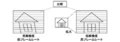
前述のように、撮像素子16からは低フレームレートの画像信号(高解像度)および高フレームレートの画像信号(低解像度)が並列に読み出される。図3に示す例では、低フレームレートの画像信号A1を読み出す間に、高フレームレート画像信号B11〜B18が読み出される。つまり、低フレームレートの画像を1枚読み出す間に、8枚の高フレームレートの画像が読み出されることになる。 As described above, a low frame rate image signal (high resolution) and a high frame rate image signal (low resolution) are read from the
高フレームレートの画像信号はローリングシャッター歪の影響を殆ど受けていないので、ここでは、高フレームレートの画像信号がローリングシャッター歪検出のための基準画像として用いられる。 Since the high frame rate image signal is hardly affected by the rolling shutter distortion, the high frame rate image signal is used as a reference image for detecting the rolling shutter distortion.
図4および図5は、図1に示すカメラ100におけるローリングシャッター歪の補正量の算出を説明するための図である。 4 and 5 are diagrams for explaining the calculation of the correction amount of the rolling shutter distortion in the
ローリングシャッター歪の補正を行う際には画像において任意の領域が切り出されるので、その画角は狭くなる。全画角に対して90%の領域を切り出す場合には、当該90%の領域において、システム制御回路50は水平方向の位置ずれを検出する。 When correcting the rolling shutter distortion, an arbitrary area is cut out in the image, and the angle of view becomes narrow. When a 90% area is cut out with respect to the entire angle of view, the
図4に示すように、高フレームレートの画像はその解像度が低いので、解像度が低い状態では低フレームレートの画像との比較ができない。このため、画像処理回路20はシステム制御回路50の制御下で低フレームレートの画像と同一の解像度になるように予め高フレームレートの画像について拡大処理(拡大補間処理)を行う。 As shown in FIG. 4, since the resolution of the high frame rate image is low, it cannot be compared with the low frame rate image when the resolution is low. For this reason, the
例えば、システム制御回路50は高フレームレート画像の任意のラインについて中央90%(m(mは2以上の整数)画素)の領域を切り出して、当該切り出し領域(拡大補間処理後の画像)と低フレームレートの画像の同一ラインとについて水平方向に沿って比較を行う。 For example, the
そして、システム制御回路50は次の式(1)を用いて、水平ずれ差分評価値Diff(x)を算出する。 Then, the

ここで、Diff(x)は水平ずれ差分評価値、LineLowFr(x,y)は低フレームレート画像の所定位置における画素値、LineHiFr(x,y)は高フレームレート画像の所定位置における画素値、Xminは差分評価値の算出開始位置、そして、Xmaxは差分評価値の算出終了位置を表す。 Here, Diff (x) is a horizontal shift difference evaluation value, LineLowFr (x, y) is a pixel value at a predetermined position of the low frame rate image, LineHiFr (x, y) is a pixel value at a predetermined position of the high frame rate image, Xmin represents the calculation start position of the difference evaluation value, and Xmax represents the calculation end position of the difference evaluation value.
上述のようにして、水平ずれ差分評価値Diff(x)(つまり、ずれ差分量)を算出した後、システム制御回路50は、図5に示すように、低フレームレート画像および高フレームレート画像を所定のラインについて水平方向にずらしつつ、差分評価値Diff(x)が最小となる位置を探索する。差分評価値Diff(x)が最少となる位置が水平方向にずれた位置となる。 After calculating the horizontal shift difference evaluation value Diff (x) (that is, the shift difference amount) as described above, the
最終的に低フレームレート画像のn(nは2以上の整数)画素中からm画素を切り出す際には、高フレームレート画像の中央m画素を切り出して低フレームレート画像との水平差分を求める。 Finally, when m pixels are cut out from n pixels (n is an integer of 2 or more) of the low frame rate image, the center m pixels of the high frame rate image are cut out to obtain a horizontal difference from the low frame rate image.
1ラインのローリングシャッター歪の補正量を求める際には、システム制御回路50は算出開始位置Xminを低フレームレート画像の左端(Xmin=0、Xmax=m)として、算出終了位置Xmaxが低フレームレート画像の右端(Xmin=a,Xmax=n)となるまで水平ずれ差分評価値Diff(x)を算出する。そして、全ての水平ずれ差分評価値Diff(x)を求めると、システム制御回路50はこれら水平ずれ差分評価値Diff(x)の最小値を求める。 When calculating the correction amount of the rolling shutter distortion for one line, the
図5に示す例では、水平ずれ差分評価値Diff(b)が最小となるbが当該ラインにおけるローリングシャッター歪の補正量となる。システム制御回路50はこのラインについては低フレームレート画像の左端からb画素の位置を基準としてm画素を切り出してローリングシャッター歪補正画像(ライン画像)とする。 In the example illustrated in FIG. 5, b where the horizontal shift difference evaluation value Diff (b) is the minimum is the rolling shutter distortion correction amount in the line. For this line, the
上述の処理を、全てのラインについて行って、システム制御回路50は切り出したライン画像を上から順に並べてローリングシャッター歪が補正された画像を生成する。 The above-described processing is performed for all lines, and the
図6は、図1に示すカメラ100においてローリングシャッター歪補正の際に加速度センサの検出結果を用いる例を説明するための図である。 FIG. 6 is a diagram for explaining an example in which the detection result of the acceleration sensor is used in rolling shutter distortion correction in the
加速度センサ71による検出結果によってカメラ100のおおよその移動量が分かるので、当該移動量を用いてローリングシャッター歪の検出範囲を狭めれば、検出処理を高速化することができる。 Since the approximate amount of movement of the
ここでは、加速度センサ71によって移動量が左方向にc画素移動したことが検出されると、左方向にc画素ずらした位置から±α画素の範囲を検出範囲(探索範囲)とする。そして、図5で説明したようにして、システム制御回路50は水平ずれ差分評価値Diff(0)〜Diff(2α−1)の範囲で差分評価値Diff(x)の最小値を探索して、ローリングシャッター歪の補正量を算出する。 Here, when it is detected by the
このようにして探索範囲を狭めれば、システム制御回路50などにおける演算処理負荷を低減して高速化で検出処理を行うことができる。上記の探索範囲は加速度センサ71の検出精度に依存し、精度が高くなるほど探索範囲を狭めることができる。 If the search range is narrowed in this way, the calculation processing load on the
図7は、図1に示すカメラ100においてローリングシャッター歪検出を失敗した場合の処理を説明するための図である。 FIG. 7 is a view for explaining processing when the rolling shutter distortion detection fails in the
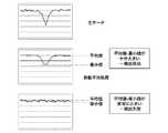
前述のように、水平ずれ差分評価値Diff(X)からその最小値を求める際には、生データ(撮像素子14の出力をA/D変換したデータ)のままではノイズが大きいので移動平均処理を行った後最小値を検出する。 As described above, when obtaining the minimum value from the horizontal shift difference evaluation value Diff (X), since the noise is large if the raw data (data obtained by A / D converting the output of the image sensor 14) is used, the moving average process is performed. After performing the above, the minimum value is detected.
従って、水平ずれ差分評価値Diff(x)の信頼性を確かめるため、システム制御回路50は全ての水平ずれ差分評価値Diff(x)の平均値と最小値との差分を求めて、当該差分が所定の値以上であれば水平ずれ差分評価値Diff(x)の信頼性が高いと判定する。そして、システム制御回路50はローリングシャッター歪の検出成功とする。 Therefore, in order to confirm the reliability of the horizontal shift difference evaluation value Diff (x), the
一方、上記の平均値と最小値との差分が所定の値未満であると、システム制御回路50は水平ずれ差分評価値Diff(x)の信頼性が低いと判定して、ローリングシャッター歪の検出失敗とする。 On the other hand, if the difference between the average value and the minimum value is less than the predetermined value, the
上記の信頼性の判定は、ライン毎に行われ、1フレームにおいて所定のライン以上の失敗があると、システム制御回路50は加速度センサ71による検出結果に応じてローリングシャッター歪の補正を行う。一方、1フレームにおいて所定のライン未満の失敗であれば、システム制御回路50は失敗したラインについては加速度センサの検出結果に応じてローリングシャッター歪の補正を行い、成功したラインについて前述のローリングシャッター歪の補正量を用いてローリングシャッター歪の補正を行う。 The reliability determination is performed for each line. When there is a failure exceeding a predetermined line in one frame, the
図8は、図1に示すカメラ100においてローリングシャッター歪検出の際のライン比較を説明するための図である。 FIG. 8 is a diagram for explaining line comparison when detecting rolling shutter distortion in the
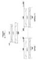
前述のように、低フレームレート画像と高フレームレート画像とはその読み出すタイミングが異なるので、比較すべきラインについて露光重心を一致させることが必要である。このため、図8に示すように、比較すべきライン(比較ライン)として露光重心が近いフレームのラインを選択する。 As described above, since the readout timings of the low frame rate image and the high frame rate image are different, it is necessary to match the exposure centroids for the lines to be compared. For this reason, as shown in FIG. 8, a line of a frame having a close exposure center of gravity is selected as a line to be compared (comparison line).
この際には、シャッター速度に応じて露光重心が異なるので、システム制御回路50はシャッター速度に応じた2画像(低フレームレート画像と高フレームレート画像)の露光重心を算出してラインの比較を行う。 In this case, since the exposure center of gravity differs according to the shutter speed, the
また、システム制御回路50は高フレームレート画像を、低フレームレート画像相当の高解像度の画像サイズに拡大補間(拡大補間処理)して、予め同一の画像サイズにする。そして、システム制御回路50は低フレームレート画像のA1フレームについて上から順にライン毎の露光重心を求めて、当該露光重心にその露光重心が近似する高フレームレート画像のフレームを選択する。 Further, the
図8に示す例では、A1フレームにおけるラインL0については、その露光重心は高フレームレート画像のラインL0においてB17フレームか又はB18フレームの露光重心が近似する。システム制御回路50はB17フレームとB18フレームとを比較してB17ラインの露光重心がA1フレームの露光銃身に近似するとして、ラインL0についてB17フレームのラインL0を比較ラインとして採用する。 In the example shown in FIG. 8, for the line L0 in the A1 frame, the exposure centroid is approximate to the exposure centroid of the B17 frame or B18 frame in the line L0 of the high frame rate image. The
同様にして、システム制御回路50はラインL1についてはB17フレームとB18フレームとを比較して、B17フレームのラインL1を比較ラインとして採用する。 Similarly, the
以下同様に、ラインL2についてはB18フレームが採用され、ラインL3についてB18フレームが採用される。また、ラインL4についてはB19フレームが採用される。 Similarly, the B18 frame is adopted for the line L2, and the B18 frame is adopted for the line L3. For the line L4, the B19 frame is adopted.
このようにして、システム制御回路50は全ラインについて露光重心が近似するフレームを選択して、水平ずれ差分評価値を算出する。 In this way, the
上述の実施の形態では、ローリングシャッター歪補正量を算出する際、1フレームにおいて所定のライン以上で検出が失敗すると、加速度センサの検出結果のみを用いて補正を行うようにしたが、1ラインでも検出に失敗すると、加速度センサの検出結果のみを用いて補正を行うようにしてもよい。 In the above-described embodiment, when the rolling shutter distortion correction amount is calculated, if detection fails at a predetermined line or more in one frame, correction is performed using only the detection result of the acceleration sensor. If the detection fails, correction may be performed using only the detection result of the acceleration sensor.
さらには、検出に失敗したラインについて加速度センサの検出結果を用いることなく、当該失敗したラインの上下のラインに応じて補間処理を行って補正量を決定するようにしてもよい。 Further, the correction amount may be determined by performing interpolation processing according to the lines above and below the failed line without using the detection result of the acceleration sensor for the line that failed to be detected.
さらに、低フレームレート画像と高フレームレート画像とを比較する際、露光重心が近いフレームを選択するようにしたが、フレーム間の補間画像を生成することによって、露光重心が合致する画像を疑似的に生成して比較を行うようにしてもよい。また、ライン方向についてもライン間の補間画像を生成して比較ラインが合致する画像を疑似的に生成して比較を行うようにしてもよい。 In addition, when comparing a low frame rate image and a high frame rate image, a frame with a close exposure centroid is selected. By generating an interpolated image between frames, an image with a matching exposure centroid is simulated. May be generated and compared. Also, with respect to the line direction, an interpolated image between the lines may be generated, and an image that matches the comparison line may be generated in a pseudo manner for comparison.
加えて、上述の実施の形態では、加速度センサの検出結果を併用しているが、カメラ100が加速度センサを備えない場合には、探索範囲を広げて検出が失敗する可能性を下げるようにすればよい。 In addition, in the above-described embodiment, the detection result of the acceleration sensor is used together. However, if the
なお、被写体の動きに起因するローリングシャッター歪については、動きベクトルの検出結果を用いてローリングシャッター歪の検出を行うようにすればよい。 As for the rolling shutter distortion caused by the motion of the subject, the rolling shutter distortion may be detected using the motion vector detection result.
このようにして、本発明の実施の形態では、CMOSセンサなどの撮像素子において読み出しタイミングに起因するローリングシャッター歪を精度よく補正して、高画質な画像を得ることができる。 In this manner, in the embodiment of the present invention, a high-quality image can be obtained by accurately correcting the rolling shutter distortion caused by the readout timing in an image sensor such as a CMOS sensor.
上述の説明から明らかなように、図1に示す例では、システム制御回路50、メモリ制御回路22、画像処理回路20、タイミング発生回路18、およびA/D変換器16が読み出し手段として機能し、システム制御回路50が補正手段として機能する。 As is clear from the above description, in the example shown in FIG. 1, the
以上、本発明について実施の形態に基づいて説明したが、本発明は、これらの実施の形態に限定されるものではなく、この発明の要旨を逸脱しない範囲の様々な形態も本発明に含まれる。 As mentioned above, although this invention was demonstrated based on embodiment, this invention is not limited to these embodiment, Various forms of the range which does not deviate from the summary of this invention are also contained in this invention. .
例えば、上記の実施の形態の機能を制御方法として、この制御方法を撮像装置に実行させるようにすればよい。また、上述の実施の形態の機能を有するプログラムを制御プログラムとして、当該制御プログラムを撮像装置が備えるコンピュータに実行させるようにしてもよい。なお、制御プログラムは、例えば、コンピュータに読み取り可能な記録媒体に記録される。 For example, the function of the above embodiment may be used as a control method, and this control method may be executed by the imaging apparatus. Further, a program having the functions of the above-described embodiments may be used as a control program, and the control program may be executed by a computer included in the imaging apparatus. The control program is recorded on a computer-readable recording medium, for example.
上記の制御方法および制御プログラムの各々は、少なくとも読み出しステップおよび補正ステップを有している。 Each of the above control method and control program has at least a reading step and a correction step.
また、本発明は、以下の処理を実行することによっても実現される。つまり、上述した実施形態の機能を実現するソフトウェア(プログラム)を、ネットワーク又は各種の記録媒体を介してシステム或いは装置に供給し、そのシステム或いは装置のコンピュータ(またはCPUやMPUなど)がプログラムを読み出して実行する処理である。 The present invention can also be realized by executing the following processing. That is, software (program) that realizes the functions of the above-described embodiments is supplied to a system or apparatus via a network or various recording media, and the computer (or CPU, MPU, etc.) of the system or apparatus reads the program. To be executed.
14 撮像素子
20 画像処理回路
22 メモリ制御回路
28 画像表示部
32 圧縮伸長回路
50 システム制御回路
62 シャッタースイッチ
66 表示切替スイッチ
70 操作部
71 加速度センサDESCRIPTION OF
Claims (8)
Translated fromJapanese前記撮像素子において所定の方向に沿った所定の数のライン毎にその読み出しタイミングを異ならせて読み出しを行って第1のフレームレートの第1の画像信号と前記第1のフレームレートよりもフレームレートが高い第2のフレームレートの第2の画像信号を出力する読み出し手段と、
前記読み出しタイミングに起因するローリングシャッター歪を補正する際、前記第2の画像信号を基準画像として前記第1の画像信号を補正して、当該補正後の第1の画像信号を画像データとする補正手段と、
を有することを特徴とする撮像装置。An image sensor comprising a plurality of photoelectric conversion elements arranged in a matrix;
In the image pickup device, reading is performed by changing the reading timing for each predetermined number of lines along a predetermined direction, and the first image signal of the first frame rate and the frame rate higher than the first frame rate. Reading means for outputting a second image signal having a high second frame rate;
When correcting the rolling shutter distortion caused by the readout timing, the first image signal is corrected using the second image signal as a reference image, and the corrected first image signal is used as image data. Means,
An imaging device comprising:
前記補正手段は、前記加速度検出手段によって検出された加速度ら応じてローリングシャッター歪を検出する探索範囲を決定することを特徴とする請求項1に記載の撮像装置。Acceleration detecting means for detecting acceleration applied to the imaging device;
The imaging apparatus according to claim 1, wherein the correction unit determines a search range in which rolling shutter distortion is detected according to accelerations detected by the acceleration detection unit.
前記撮像素子において所定の方向に沿った所定の数のライン毎にその読み出しタイミングを異ならせて読み出しを行って第1のフレームレートの第1の画像信号と前記第1のフレームレートよりもフレームレートが高い第2のフレームレートの第2の画像信号を出力する読み出しステップと、
前記読み出しタイミングに起因するローリングシャッター歪を補正する際、前記第2の画像信号を基準画像として前記第1の画像信号を補正して、当該補正後の第1の画像信号を画像データとする補正ステップと、
を有することを特徴とする制御方法。A method for controlling an imaging apparatus including an imaging element including a plurality of photoelectric conversion elements arranged in a matrix,
In the image pickup device, reading is performed by changing the reading timing for each predetermined number of lines along a predetermined direction, and the first image signal of the first frame rate and the frame rate higher than the first frame rate. A readout step of outputting a second image signal having a high second frame rate;
When correcting the rolling shutter distortion caused by the readout timing, the first image signal is corrected using the second image signal as a reference image, and the corrected first image signal is used as image data. Steps,
A control method characterized by comprising:
前記撮像装置が備えるコンピュータに、
前記撮像素子において所定の方向に沿った所定の数のライン毎にその読み出しタイミングを異ならせて読み出しを行って第1のフレームレートの第1の画像信号と前記第1のフレームレートよりもフレームレートが高い第2のフレームレートの第2の画像信号を出力する読み出しステップと、
前記読み出しタイミングに起因するローリングシャッター歪を補正する際、前記第2の画像信号を基準画像として前記第1の画像信号を補正して、当該補正後の第1の画像信号を画像データとする補正ステップと、
を実行させることを特徴とする制御プログラム。A control program used in an imaging apparatus including an imaging device including a plurality of photoelectric conversion elements arranged in a matrix,
In the computer provided in the imaging device,
In the image pickup device, reading is performed by changing the reading timing for each predetermined number of lines along a predetermined direction, and the first image signal of the first frame rate and the frame rate higher than the first frame rate. A readout step of outputting a second image signal having a high second frame rate;
When correcting the rolling shutter distortion caused by the readout timing, the first image signal is corrected using the second image signal as a reference image, and the corrected first image signal is used as image data. Steps,
A control program characterized by causing
Priority Applications (1)
| Application Number | Priority Date | Filing Date | Title |
|---|---|---|---|
| JP2012288035AJP2014131190A (en) | 2012-12-28 | 2012-12-28 | Image pick-up apparatus, control method thereof, and control program |
Applications Claiming Priority (1)
| Application Number | Priority Date | Filing Date | Title |
|---|---|---|---|
| JP2012288035AJP2014131190A (en) | 2012-12-28 | 2012-12-28 | Image pick-up apparatus, control method thereof, and control program |
Publications (1)
| Publication Number | Publication Date |
|---|---|
| JP2014131190Atrue JP2014131190A (en) | 2014-07-10 |
Family
ID=51409205
Family Applications (1)
| Application Number | Title | Priority Date | Filing Date |
|---|---|---|---|
| JP2012288035APendingJP2014131190A (en) | 2012-12-28 | 2012-12-28 | Image pick-up apparatus, control method thereof, and control program |
Country Status (1)
| Country | Link |
|---|---|
| JP (1) | JP2014131190A (en) |
Cited By (6)
| Publication number | Priority date | Publication date | Assignee | Title |
|---|---|---|---|---|
| JP2016134631A (en)* | 2015-01-15 | 2016-07-25 | キヤノン株式会社 | Image processing device, imaging device, and image processing method |
| JP2017085245A (en)* | 2015-10-23 | 2017-05-18 | キヤノン株式会社 | Imaging apparatus and image distortion detection method |
| JP2018033100A (en)* | 2016-08-26 | 2018-03-01 | キヤノン株式会社 | Image processing apparatus and method, and imaging apparatus |
| CN114205525A (en)* | 2021-12-02 | 2022-03-18 | 信利光电股份有限公司 | Image correction method and device for roller shutter exposure and readable storage medium |
| CN114359014A (en)* | 2020-09-30 | 2022-04-15 | 安霸国际有限合伙企业 | Dynamic Driver Mechanism for Rolling Shutter Sensors for Structured Light Patterning |
| CN115866401A (en)* | 2021-12-06 | 2023-03-28 | 黑芝麻智能科技(重庆)有限公司 | Method for reducing global motion and rolling shutter effect in dual-camera system |
- 2012
- 2012-12-28JPJP2012288035Apatent/JP2014131190A/enactivePending
Cited By (8)
| Publication number | Priority date | Publication date | Assignee | Title |
|---|---|---|---|---|
| JP2016134631A (en)* | 2015-01-15 | 2016-07-25 | キヤノン株式会社 | Image processing device, imaging device, and image processing method |
| JP2017085245A (en)* | 2015-10-23 | 2017-05-18 | キヤノン株式会社 | Imaging apparatus and image distortion detection method |
| JP2018033100A (en)* | 2016-08-26 | 2018-03-01 | キヤノン株式会社 | Image processing apparatus and method, and imaging apparatus |
| CN114359014A (en)* | 2020-09-30 | 2022-04-15 | 安霸国际有限合伙企业 | Dynamic Driver Mechanism for Rolling Shutter Sensors for Structured Light Patterning |
| CN114359014B (en)* | 2020-09-30 | 2025-02-25 | 安霸国际有限合伙企业 | Dynamic actuator mechanism for rolling shutter sensor to obtain structured light patterns |
| CN114205525A (en)* | 2021-12-02 | 2022-03-18 | 信利光电股份有限公司 | Image correction method and device for roller shutter exposure and readable storage medium |
| CN114205525B (en)* | 2021-12-02 | 2024-05-31 | 信利光电股份有限公司 | Roller shutter exposure image correction method and device and readable storage medium |
| CN115866401A (en)* | 2021-12-06 | 2023-03-28 | 黑芝麻智能科技(重庆)有限公司 | Method for reducing global motion and rolling shutter effect in dual-camera system |
Similar Documents
| Publication | Publication Date | Title |
|---|---|---|
| JP7009142B2 (en) | Image pickup device and image processing method | |
| JP5054583B2 (en) | Imaging device | |
| CN105580349B (en) | Image processing apparatus, photographic device and image processing method | |
| EP2882183B1 (en) | Electronic apparatus and method of controlling the same | |
| US9942476B2 (en) | Image capturing apparatus and image capturing method | |
| JP5782813B2 (en) | Imaging apparatus and image display method | |
| JP2011199565A (en) | Imaging device and program | |
| JP4605217B2 (en) | Imaging apparatus and program thereof | |
| JP2012222495A (en) | Image processor, image processing method, and program | |
| JP2014131190A (en) | Image pick-up apparatus, control method thereof, and control program | |
| CN107079092A (en) | Imaging device, imaging method, processing program | |
| CN104717424A (en) | Image processing apparatus, camera equipment, and control method thereof | |
| JP6827854B2 (en) | Image processing equipment and methods, and imaging equipment | |
| JP2019153208A (en) | Image processor, method for processing image, and program | |
| JP2012165405A (en) | Imaging apparatus and program | |
| JP5780885B2 (en) | Imaging device, control method thereof, and control program | |
| CN114554041A (en) | Image pickup apparatus, image pickup method, and storage medium | |
| JP5742237B2 (en) | Imaging apparatus and imaging method | |
| JP6559014B2 (en) | Imaging apparatus, control method thereof, and program | |
| JP2014168209A (en) | Imaging apparatus, imaging method and program | |
| JP2018006888A (en) | Imaging apparatus, control method therefor, and control program | |
| JP4687619B2 (en) | Image processing apparatus, image processing method, and program | |
| WO2024143042A1 (en) | Image processing device, image processing method, and storage medium | |
| JP7523914B2 (en) | Image capture device and control method thereof | |
| JP2017038300A (en) | Image processing apparatus and method |