JP2014124033A - Relay machine, connector device, charging cable and power supply system - Google Patents
Relay machine, connector device, charging cable and power supply systemDownload PDFInfo
- Publication number
- JP2014124033A JP2014124033AJP2012278625AJP2012278625AJP2014124033AJP 2014124033 AJP2014124033 AJP 2014124033AJP 2012278625 AJP2012278625 AJP 2012278625AJP 2012278625 AJP2012278625 AJP 2012278625AJP 2014124033 AJP2014124033 AJP 2014124033A
- Authority
- JP
- Japan
- Prior art keywords
- communication unit
- charging
- control
- vehicle
- transmits
- Prior art date
- Legal status (The legal status is an assumption and is not a legal conclusion. Google has not performed a legal analysis and makes no representation as to the accuracy of the status listed.)
- Granted
Links
- 238000004891communicationMethods0.000claimsabstractdescription210
- 238000000034methodMethods0.000description16
- 238000001514detection methodMethods0.000description14
- 238000010586diagramMethods0.000description12
- 230000005540biological transmissionEffects0.000description7
- 238000012790confirmationMethods0.000description7
- 238000009413insulationMethods0.000description7
- 230000006870functionEffects0.000description5
- 238000012986modificationMethods0.000description5
- 230000004048modificationEffects0.000description5
- 238000002360preparation methodMethods0.000description5
- 239000003990capacitorSubstances0.000description4
- 238000012545processingMethods0.000description4
- 241000156302Porcine hemagglutinating encephalomyelitis virusSpecies0.000description2
- 230000005856abnormalityEffects0.000description2
- 230000004913activationEffects0.000description2
- 238000006243chemical reactionMethods0.000description2
- 230000000694effectsEffects0.000description2
- 230000015556catabolic processEffects0.000description1
- 230000003247decreasing effectEffects0.000description1
- 238000011161developmentMethods0.000description1
- 230000007613environmental effectEffects0.000description1
- 238000003780insertionMethods0.000description1
- 230000037431insertionEffects0.000description1
- 239000011347resinSubstances0.000description1
- 229920005989resinPolymers0.000description1
- 238000011144upstream manufacturingMethods0.000description1
- 238000010792warmingMethods0.000description1
Images


Classifications
- H—ELECTRICITY
- H01—ELECTRIC ELEMENTS
- H01M—PROCESSES OR MEANS, e.g. BATTERIES, FOR THE DIRECT CONVERSION OF CHEMICAL ENERGY INTO ELECTRICAL ENERGY
- H01M10/00—Secondary cells; Manufacture thereof
- H01M10/42—Methods or arrangements for servicing or maintenance of secondary cells or secondary half-cells
- H01M10/44—Methods for charging or discharging
- B—PERFORMING OPERATIONS; TRANSPORTING
- B60—VEHICLES IN GENERAL
- B60L—PROPULSION OF ELECTRICALLY-PROPELLED VEHICLES; SUPPLYING ELECTRIC POWER FOR AUXILIARY EQUIPMENT OF ELECTRICALLY-PROPELLED VEHICLES; ELECTRODYNAMIC BRAKE SYSTEMS FOR VEHICLES IN GENERAL; MAGNETIC SUSPENSION OR LEVITATION FOR VEHICLES; MONITORING OPERATING VARIABLES OF ELECTRICALLY-PROPELLED VEHICLES; ELECTRIC SAFETY DEVICES FOR ELECTRICALLY-PROPELLED VEHICLES
- B60L3/00—Electric devices on electrically-propelled vehicles for safety purposes; Monitoring operating variables, e.g. speed, deceleration or energy consumption
- B60L3/0023—Detecting, eliminating, remedying or compensating for drive train abnormalities, e.g. failures within the drive train
- B60L3/0069—Detecting, eliminating, remedying or compensating for drive train abnormalities, e.g. failures within the drive train relating to the isolation, e.g. ground fault or leak current
- B—PERFORMING OPERATIONS; TRANSPORTING
- B60—VEHICLES IN GENERAL
- B60L—PROPULSION OF ELECTRICALLY-PROPELLED VEHICLES; SUPPLYING ELECTRIC POWER FOR AUXILIARY EQUIPMENT OF ELECTRICALLY-PROPELLED VEHICLES; ELECTRODYNAMIC BRAKE SYSTEMS FOR VEHICLES IN GENERAL; MAGNETIC SUSPENSION OR LEVITATION FOR VEHICLES; MONITORING OPERATING VARIABLES OF ELECTRICALLY-PROPELLED VEHICLES; ELECTRIC SAFETY DEVICES FOR ELECTRICALLY-PROPELLED VEHICLES
- B60L3/00—Electric devices on electrically-propelled vehicles for safety purposes; Monitoring operating variables, e.g. speed, deceleration or energy consumption
- B60L3/04—Cutting off the power supply under fault conditions
- B—PERFORMING OPERATIONS; TRANSPORTING
- B60—VEHICLES IN GENERAL
- B60L—PROPULSION OF ELECTRICALLY-PROPELLED VEHICLES; SUPPLYING ELECTRIC POWER FOR AUXILIARY EQUIPMENT OF ELECTRICALLY-PROPELLED VEHICLES; ELECTRODYNAMIC BRAKE SYSTEMS FOR VEHICLES IN GENERAL; MAGNETIC SUSPENSION OR LEVITATION FOR VEHICLES; MONITORING OPERATING VARIABLES OF ELECTRICALLY-PROPELLED VEHICLES; ELECTRIC SAFETY DEVICES FOR ELECTRICALLY-PROPELLED VEHICLES
- B60L53/00—Methods of charging batteries, specially adapted for electric vehicles; Charging stations or on-board charging equipment therefor; Exchange of energy storage elements in electric vehicles
- B60L53/10—Methods of charging batteries, specially adapted for electric vehicles; Charging stations or on-board charging equipment therefor; Exchange of energy storage elements in electric vehicles characterised by the energy transfer between the charging station and the vehicle
- B60L53/11—DC charging controlled by the charging station, e.g. mode 4
- B—PERFORMING OPERATIONS; TRANSPORTING
- B60—VEHICLES IN GENERAL
- B60L—PROPULSION OF ELECTRICALLY-PROPELLED VEHICLES; SUPPLYING ELECTRIC POWER FOR AUXILIARY EQUIPMENT OF ELECTRICALLY-PROPELLED VEHICLES; ELECTRODYNAMIC BRAKE SYSTEMS FOR VEHICLES IN GENERAL; MAGNETIC SUSPENSION OR LEVITATION FOR VEHICLES; MONITORING OPERATING VARIABLES OF ELECTRICALLY-PROPELLED VEHICLES; ELECTRIC SAFETY DEVICES FOR ELECTRICALLY-PROPELLED VEHICLES
- B60L53/00—Methods of charging batteries, specially adapted for electric vehicles; Charging stations or on-board charging equipment therefor; Exchange of energy storage elements in electric vehicles
- B60L53/10—Methods of charging batteries, specially adapted for electric vehicles; Charging stations or on-board charging equipment therefor; Exchange of energy storage elements in electric vehicles characterised by the energy transfer between the charging station and the vehicle
- B60L53/14—Conductive energy transfer
- B60L53/18—Cables specially adapted for charging electric vehicles
- B—PERFORMING OPERATIONS; TRANSPORTING
- B60—VEHICLES IN GENERAL
- B60L—PROPULSION OF ELECTRICALLY-PROPELLED VEHICLES; SUPPLYING ELECTRIC POWER FOR AUXILIARY EQUIPMENT OF ELECTRICALLY-PROPELLED VEHICLES; ELECTRODYNAMIC BRAKE SYSTEMS FOR VEHICLES IN GENERAL; MAGNETIC SUSPENSION OR LEVITATION FOR VEHICLES; MONITORING OPERATING VARIABLES OF ELECTRICALLY-PROPELLED VEHICLES; ELECTRIC SAFETY DEVICES FOR ELECTRICALLY-PROPELLED VEHICLES
- B60L53/00—Methods of charging batteries, specially adapted for electric vehicles; Charging stations or on-board charging equipment therefor; Exchange of energy storage elements in electric vehicles
- B60L53/60—Monitoring or controlling charging stations
- B60L53/65—Monitoring or controlling charging stations involving identification of vehicles or their battery types
- H—ELECTRICITY
- H02—GENERATION; CONVERSION OR DISTRIBUTION OF ELECTRIC POWER
- H02J—CIRCUIT ARRANGEMENTS OR SYSTEMS FOR SUPPLYING OR DISTRIBUTING ELECTRIC POWER; SYSTEMS FOR STORING ELECTRIC ENERGY
- H02J5/00—Circuit arrangements for transfer of electric power between AC networks and DC networks
- H—ELECTRICITY
- H02—GENERATION; CONVERSION OR DISTRIBUTION OF ELECTRIC POWER
- H02J—CIRCUIT ARRANGEMENTS OR SYSTEMS FOR SUPPLYING OR DISTRIBUTING ELECTRIC POWER; SYSTEMS FOR STORING ELECTRIC ENERGY
- H02J7/00—Circuit arrangements for charging or depolarising batteries or for supplying loads from batteries
- H02J7/02—Circuit arrangements for charging or depolarising batteries or for supplying loads from batteries for charging batteries from AC mains by converters
- B—PERFORMING OPERATIONS; TRANSPORTING
- B60—VEHICLES IN GENERAL
- B60L—PROPULSION OF ELECTRICALLY-PROPELLED VEHICLES; SUPPLYING ELECTRIC POWER FOR AUXILIARY EQUIPMENT OF ELECTRICALLY-PROPELLED VEHICLES; ELECTRODYNAMIC BRAKE SYSTEMS FOR VEHICLES IN GENERAL; MAGNETIC SUSPENSION OR LEVITATION FOR VEHICLES; MONITORING OPERATING VARIABLES OF ELECTRICALLY-PROPELLED VEHICLES; ELECTRIC SAFETY DEVICES FOR ELECTRICALLY-PROPELLED VEHICLES
- B60L2210/00—Converter types
- B60L2210/30—AC to DC converters
- H—ELECTRICITY
- H01—ELECTRIC ELEMENTS
- H01M—PROCESSES OR MEANS, e.g. BATTERIES, FOR THE DIRECT CONVERSION OF CHEMICAL ENERGY INTO ELECTRICAL ENERGY
- H01M2220/00—Batteries for particular applications
- H01M2220/20—Batteries in motive systems, e.g. vehicle, ship, plane
- Y—GENERAL TAGGING OF NEW TECHNOLOGICAL DEVELOPMENTS; GENERAL TAGGING OF CROSS-SECTIONAL TECHNOLOGIES SPANNING OVER SEVERAL SECTIONS OF THE IPC; TECHNICAL SUBJECTS COVERED BY FORMER USPC CROSS-REFERENCE ART COLLECTIONS [XRACs] AND DIGESTS
- Y02—TECHNOLOGIES OR APPLICATIONS FOR MITIGATION OR ADAPTATION AGAINST CLIMATE CHANGE
- Y02E—REDUCTION OF GREENHOUSE GAS [GHG] EMISSIONS, RELATED TO ENERGY GENERATION, TRANSMISSION OR DISTRIBUTION
- Y02E60/00—Enabling technologies; Technologies with a potential or indirect contribution to GHG emissions mitigation
- Y02E60/10—Energy storage using batteries
- Y—GENERAL TAGGING OF NEW TECHNOLOGICAL DEVELOPMENTS; GENERAL TAGGING OF CROSS-SECTIONAL TECHNOLOGIES SPANNING OVER SEVERAL SECTIONS OF THE IPC; TECHNICAL SUBJECTS COVERED BY FORMER USPC CROSS-REFERENCE ART COLLECTIONS [XRACs] AND DIGESTS
- Y02—TECHNOLOGIES OR APPLICATIONS FOR MITIGATION OR ADAPTATION AGAINST CLIMATE CHANGE
- Y02T—CLIMATE CHANGE MITIGATION TECHNOLOGIES RELATED TO TRANSPORTATION
- Y02T10/00—Road transport of goods or passengers
- Y02T10/60—Other road transportation technologies with climate change mitigation effect
- Y02T10/70—Energy storage systems for electromobility, e.g. batteries
- Y—GENERAL TAGGING OF NEW TECHNOLOGICAL DEVELOPMENTS; GENERAL TAGGING OF CROSS-SECTIONAL TECHNOLOGIES SPANNING OVER SEVERAL SECTIONS OF THE IPC; TECHNICAL SUBJECTS COVERED BY FORMER USPC CROSS-REFERENCE ART COLLECTIONS [XRACs] AND DIGESTS
- Y02—TECHNOLOGIES OR APPLICATIONS FOR MITIGATION OR ADAPTATION AGAINST CLIMATE CHANGE
- Y02T—CLIMATE CHANGE MITIGATION TECHNOLOGIES RELATED TO TRANSPORTATION
- Y02T10/00—Road transport of goods or passengers
- Y02T10/60—Other road transportation technologies with climate change mitigation effect
- Y02T10/7072—Electromobility specific charging systems or methods for batteries, ultracapacitors, supercapacitors or double-layer capacitors
- Y—GENERAL TAGGING OF NEW TECHNOLOGICAL DEVELOPMENTS; GENERAL TAGGING OF CROSS-SECTIONAL TECHNOLOGIES SPANNING OVER SEVERAL SECTIONS OF THE IPC; TECHNICAL SUBJECTS COVERED BY FORMER USPC CROSS-REFERENCE ART COLLECTIONS [XRACs] AND DIGESTS
- Y02—TECHNOLOGIES OR APPLICATIONS FOR MITIGATION OR ADAPTATION AGAINST CLIMATE CHANGE
- Y02T—CLIMATE CHANGE MITIGATION TECHNOLOGIES RELATED TO TRANSPORTATION
- Y02T10/00—Road transport of goods or passengers
- Y02T10/60—Other road transportation technologies with climate change mitigation effect
- Y02T10/72—Electric energy management in electromobility
- Y—GENERAL TAGGING OF NEW TECHNOLOGICAL DEVELOPMENTS; GENERAL TAGGING OF CROSS-SECTIONAL TECHNOLOGIES SPANNING OVER SEVERAL SECTIONS OF THE IPC; TECHNICAL SUBJECTS COVERED BY FORMER USPC CROSS-REFERENCE ART COLLECTIONS [XRACs] AND DIGESTS
- Y02—TECHNOLOGIES OR APPLICATIONS FOR MITIGATION OR ADAPTATION AGAINST CLIMATE CHANGE
- Y02T—CLIMATE CHANGE MITIGATION TECHNOLOGIES RELATED TO TRANSPORTATION
- Y02T90/00—Enabling technologies or technologies with a potential or indirect contribution to GHG emissions mitigation
- Y02T90/10—Technologies relating to charging of electric vehicles
- Y02T90/12—Electric charging stations
- Y—GENERAL TAGGING OF NEW TECHNOLOGICAL DEVELOPMENTS; GENERAL TAGGING OF CROSS-SECTIONAL TECHNOLOGIES SPANNING OVER SEVERAL SECTIONS OF THE IPC; TECHNICAL SUBJECTS COVERED BY FORMER USPC CROSS-REFERENCE ART COLLECTIONS [XRACs] AND DIGESTS
- Y02—TECHNOLOGIES OR APPLICATIONS FOR MITIGATION OR ADAPTATION AGAINST CLIMATE CHANGE
- Y02T—CLIMATE CHANGE MITIGATION TECHNOLOGIES RELATED TO TRANSPORTATION
- Y02T90/00—Enabling technologies or technologies with a potential or indirect contribution to GHG emissions mitigation
- Y02T90/10—Technologies relating to charging of electric vehicles
- Y02T90/14—Plug-in electric vehicles
- Y—GENERAL TAGGING OF NEW TECHNOLOGICAL DEVELOPMENTS; GENERAL TAGGING OF CROSS-SECTIONAL TECHNOLOGIES SPANNING OVER SEVERAL SECTIONS OF THE IPC; TECHNICAL SUBJECTS COVERED BY FORMER USPC CROSS-REFERENCE ART COLLECTIONS [XRACs] AND DIGESTS
- Y02—TECHNOLOGIES OR APPLICATIONS FOR MITIGATION OR ADAPTATION AGAINST CLIMATE CHANGE
- Y02T—CLIMATE CHANGE MITIGATION TECHNOLOGIES RELATED TO TRANSPORTATION
- Y02T90/00—Enabling technologies or technologies with a potential or indirect contribution to GHG emissions mitigation
- Y02T90/10—Technologies relating to charging of electric vehicles
- Y02T90/16—Information or communication technologies improving the operation of electric vehicles
- Y02T90/167—Systems integrating technologies related to power network operation and communication or information technologies for supporting the interoperability of electric or hybrid vehicles, i.e. smartgrids as interface for battery charging of electric vehicles [EV] or hybrid vehicles [HEV]
- Y—GENERAL TAGGING OF NEW TECHNOLOGICAL DEVELOPMENTS; GENERAL TAGGING OF CROSS-SECTIONAL TECHNOLOGIES SPANNING OVER SEVERAL SECTIONS OF THE IPC; TECHNICAL SUBJECTS COVERED BY FORMER USPC CROSS-REFERENCE ART COLLECTIONS [XRACs] AND DIGESTS
- Y04—INFORMATION OR COMMUNICATION TECHNOLOGIES HAVING AN IMPACT ON OTHER TECHNOLOGY AREAS
- Y04S—SYSTEMS INTEGRATING TECHNOLOGIES RELATED TO POWER NETWORK OPERATION, COMMUNICATION OR INFORMATION TECHNOLOGIES FOR IMPROVING THE ELECTRICAL POWER GENERATION, TRANSMISSION, DISTRIBUTION, MANAGEMENT OR USAGE, i.e. SMART GRIDS
- Y04S30/00—Systems supporting specific end-user applications in the sector of transportation
- Y04S30/10—Systems supporting the interoperability of electric or hybrid vehicles
- Y04S30/14—Details associated with the interoperability, e.g. vehicle recognition, authentication, identification or billing
Landscapes
- Engineering & Computer Science (AREA)
- Power Engineering (AREA)
- Transportation (AREA)
- Mechanical Engineering (AREA)
- Sustainable Energy (AREA)
- Sustainable Development (AREA)
- Life Sciences & Earth Sciences (AREA)
- Manufacturing & Machinery (AREA)
- Chemical & Material Sciences (AREA)
- Chemical Kinetics & Catalysis (AREA)
- Electrochemistry (AREA)
- General Chemical & Material Sciences (AREA)
- Charge And Discharge Circuits For Batteries Or The Like (AREA)
- Electric Propulsion And Braking For Vehicles (AREA)
- Secondary Cells (AREA)
Abstract
Translated fromJapaneseDescription
Translated fromJapanese本発明は、車輌及び充電スタンドの間でバッテリ充電に係る制御信号を中継する中継機、該中継機を備えたコネクタ装置、充電ケーブル及び給電システムに関する。 The present invention relates to a relay device that relays a control signal related to battery charging between a vehicle and a charging station, a connector device including the relay device, a charging cable, and a power feeding system.
近年、環境意識の高まりや地球温暖化対策のため、モータ及びエンジンを併用したハイブリッド自動車(HEV:Hybrid Electric Vehicle)、プラグインハイブリッド自動車(PHEV:Plug-in Hybrid Electric Vehicle)が普及している。またエンジンを備えず、電動モータで駆動する電気自動車(EV:electric vehicle)が普及している。 In recent years, hybrid electric vehicles (HEV: Hybrid Electric Vehicle) and plug-in hybrid electric vehicles (PHEV: Plug-in Hybrid Electric Vehicle) using both a motor and an engine have become widespread in order to raise environmental awareness and combat global warming. In addition, an electric vehicle (EV) that does not include an engine and is driven by an electric motor has become widespread.
モータを駆動するためのバッテリの充電方法としてはAC充電と、DC充電とがある。DC充電の方式としてはチャデモ(CHAdeMO)規格及びコンボ(Combo)方式がある。チャデモ規格に準拠した充電スタンドはDC充電用コネクタを有し、車輌との通信をCAN(Controller Area Network)通信にて行う。一方、コンボ方式に準拠した充電スタンドはDC充電用コネクタ及びAC充電用コネクタを有し、車輌との通信をインバンド通信にて行う。インバンド通信は、簡単な情報通信に利用される矩形波の制御信号に周波数2〜30MHzの制御信号を重畳させて行う通信方式である。 Battery charging methods for driving the motor include AC charging and DC charging. As a method of DC charging, there are a CHAdeMO standard and a Combo method. The charging stand compliant with the CHAdeMO standard has a DC charging connector, and communicates with the vehicle by CAN (Controller Area Network) communication. On the other hand, a charging stand compliant with the combo system has a DC charging connector and an AC charging connector, and performs communication with the vehicle by in-band communication. In-band communication is a communication method performed by superimposing a control signal with a frequency of 2 to 30 MHz on a rectangular wave control signal used for simple information communication.
ところで、DC充電の両規格が共に採用された場合、自動車メーカは2種類のDC充電規格に対応しなければならず、開発コストが増加するという問題がある。 By the way, when both standards of DC charging are adopted, there is a problem that the automobile manufacturer has to cope with two types of DC charging standards, and the development cost increases.
本発明は斯かる事情に鑑みてなされたものであり、DC充電規格が異なる車輌及び充電スタンド間で充電に係る制御信号を中継することにより、規格が異なる充電スタンドによるバッテリ充電を低コストで実現する中継機を提供することにある。
また、前記中継機を備えたコネクタ装置、充電ケーブル及び給電システムを提供することを目的とする。The present invention has been made in view of such circumstances. By relaying a control signal related to charging between a vehicle and a charging stand having different DC charging standards, battery charging by charging stations having different standards can be realized at low cost. It is to provide a repeater to perform.
It is another object of the present invention to provide a connector device, a charging cable, and a power feeding system that include the relay device.
本発明に係る中継機は、バッテリを搭載した車輌と、充電ケーブルを通じて直流を供給することにより該バッテリを充電する充電スタンドとの間で充電に係る制御信号を中継する中継機において、前記充電スタンドとの間でアナログの制御信号を送受信するアナログ制御通信部と、前記充電スタンドとの間でCAN通信プロトコルに従って制御信号を送受信するCAN通信部と、前記車輌との間でパルス波の制御信号を送受信するパルス信号通信部と、前記パルス波の制御信号に重畳した他の制御信号を送受信するインバンド通信部と、前記アナログ制御通信部及び前記CAN通信部にて受信した制御信号に応じた信号を前記パルス信号通信部及び前記インバンド通信部に送信させ、前記パルス信号通信部及び前記インバンド通信部にて受信した制御信号に応じた信号を前記アナログ制御通信部及び前記CAN通信部に送信させる制御部とを備えることを特徴とする。 The relay device according to the present invention is a relay device that relays a control signal related to charging between a vehicle equipped with a battery and a charging station that charges the battery by supplying direct current through a charging cable. An analog control communication unit that transmits and receives analog control signals to and from the charging station, a CAN communication unit that transmits and receives control signals according to a CAN communication protocol, and a pulse wave control signal between the vehicle and the vehicle A signal corresponding to the control signal received by the pulse signal communication unit for transmitting and receiving, the in-band communication unit for transmitting and receiving another control signal superimposed on the control signal of the pulse wave, and the analog control communication unit and the CAN communication unit Is transmitted to the pulse signal communication unit and the in-band communication unit, and received by the pulse signal communication unit and the in-band communication unit. Characterized in that it comprises a signal corresponding to the control signal and a control unit for transmitting to said analog control communication unit and the CAN communication unit has.
本発明にあっては、車輌及び充電スタンドは、異なる通信方式で制御信号を送受信する。中継機は車輌と、充電スタンドとの間で制御信号を中継することにより、車輌と、充電スタンドとの制御信号の送受信を可能にする。具体的には、中継機は、充電スタンドとの間ではアナログ制御通信部又はCAN通信部を用いて制御信号を送受信し、車輌との間ではパルス信号通信部又はインバンド通信部を用いて制御信号を送受信することにより、制御信号を中継する。 In the present invention, the vehicle and the charging station transmit and receive control signals using different communication methods. The relay machine relays control signals between the vehicle and the charging station, thereby enabling transmission and reception of control signals between the vehicle and the charging station. Specifically, the repeater transmits / receives a control signal using an analog control communication unit or a CAN communication unit to / from a charging station, and controls using a pulse signal communication unit or an in-band communication unit to / from a vehicle. The control signal is relayed by transmitting and receiving the signal.
本発明に係る中継機は、各通信部に給電する電源を備えることを特徴とする。 The repeater according to the present invention includes a power source that supplies power to each communication unit.
本発明にあっては、電源から給電されて各通信部が動作する。特に充電スタンド及びバッテリ以外の電源を備えることにより、中継機における電力供給の安全性を向上させることが可能である。 In the present invention, power is supplied from the power source to operate each communication unit. In particular, by providing a power supply other than the charging stand and the battery, it is possible to improve the safety of power supply in the repeater.
本発明に係る中継機は、前記バッテリを充電するための交流が入力する車輌側端子を絶縁する絶縁部を備えることを特徴とする。 The repeater according to the present invention includes an insulating portion that insulates a vehicle-side terminal to which an alternating current for charging the battery is input.
本発明にあっては、絶縁部が車輌側端子を絶縁している。従って車輌側端子からバッテリ電流が外部へ供給される不測の事態を防止することが可能である。 In the present invention, the insulating portion insulates the vehicle side terminal. Therefore, it is possible to prevent an unexpected situation where the battery current is supplied to the outside from the vehicle side terminal.
本発明に係る中継機は、前記充電スタンドから前記バッテリへの給電を遮断する遮断スイッチを備えることを特徴とする。 The repeater according to the present invention includes a cut-off switch that cuts off power supply from the charging stand to the battery.
本発明にあっては、車輌又は充電スタンド、若しくは中継機に異常があった場合、遮断スイッチによって、充電スタンドからバッテリへの給電を遮断することが可能である。 In the present invention, when there is an abnormality in the vehicle, the charging stand, or the relay machine, the power supply from the charging stand to the battery can be cut off by the cut-off switch.
本発明に係るコネクタ装置は、バッテリを搭載した車輌と、充電ケーブルとを接続するコネクタ装置において、上述のいずれか一つの中継機を備えることを特徴とする。 A connector device according to the present invention is a connector device that connects a vehicle equipped with a battery and a charging cable, and includes any one of the above-described repeaters.
本発明にあっては、バッテリを搭載した車輌と、充電ケーブルとを接続するコネクタ装置が、制御信号を中継することにより、車輌と、充電スタンドとの間で制御信号の送受信を可能にする。 In the present invention, the connector device that connects the vehicle equipped with the battery and the charging cable relays the control signal, thereby enabling transmission and reception of the control signal between the vehicle and the charging station.
本発明に係る充電ケーブルは、車輌に搭載されたバッテリに直流を供給する充電ケーブルにおいて、上述のいずれか一つの中継機を備えることを特徴とする。 A charging cable according to the present invention is a charging cable for supplying a direct current to a battery mounted on a vehicle, and includes any one of the above-described repeaters.
本発明にあっては、車輌に搭載されたバッテリに電力を供給する充電ケーブルが、制御信号を中継することにより、車輌と、充電スタンドとの間で制御信号の送受信を可能にする。 In the present invention, the charging cable that supplies power to the battery mounted on the vehicle relays the control signal, thereby enabling transmission and reception of the control signal between the vehicle and the charging station.
本発明に係る給電システムは、上述のいずれか一つの中継機と、該中継機との間でアナログの制御信号を送受信するアナログ制御通信部、及び前記中継機との間でCAN通信プロトコルに従って制御信号を送受信するCAN通信部を有する充電スタンドとを備えることを特徴とする。 The power supply system according to the present invention is controlled according to a CAN communication protocol between any one of the above repeaters, an analog control communication unit that transmits / receives an analog control signal to / from the repeater, and the repeater. And a charging station having a CAN communication unit for transmitting and receiving signals.
本発明にあっては、充電スタンド及び中継機を備えたシステムで上述の機能を実現する。 In the present invention, the above-described function is realized by a system including a charging stand and a repeater.
本発明に係る給電システムは、上述のいずれか一つの中継機と、該中継機との間でアナログの制御信号を送受信するアナログ制御通信部及び前記中継機との間でCAN通信プロトコルに従って制御信号を送受信するCAN通信部を有する充電スタンドと、前記中継機との間でパルス波の制御信号を送受信するパルス信号通信部及び該パルス波の制御信号に重畳した他の制御信号を送受信するインバンド通信部を有する車輌とを備えることを特徴とする。 The power supply system according to the present invention includes a control signal according to a CAN communication protocol between any one of the above repeaters, an analog control communication unit that transmits / receives an analog control signal to / from the repeater, and the repeater. A charging station having a CAN communication unit for transmitting and receiving a pulse signal and a pulse signal communication unit for transmitting and receiving a pulse wave control signal between the repeater and an in-band for transmitting and receiving other control signals superimposed on the pulse wave control signal And a vehicle having a communication unit.
本発明にあっては、充電スタンド、車輌及び中継機を備えたシステムで上述の機能を実現する。 In the present invention, the above-described function is realized by a system including a charging stand, a vehicle, and a repeater.
本発明によれば、DC充電規格が異なる車輌と、充電スタンドとの間で充電に係る制御信号を中継することにより、規格が異なる充電スタンドによるバッテリ充電を低コストで実現することができる。 According to the present invention, by relaying a control signal related to charging between a vehicle having a different DC charging standard and a charging station, battery charging by a charging station having a different standard can be realized at low cost.
(実施の形態1)
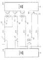
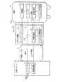
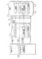
図1は実施の形態1に係る給電システムの一構成例を示したブロック図、図2は給電システムの細部を示したブロック図である。本実施の形態1に係る給電システムは、充電ケーブル2を介してバッテリ充電を行う充電スタンド1と、充電ケーブル2を車輌4に接続するためのコネクタ装置3と、外部からの電力で充電できるハイブリッド自動車、電気自動車等の車輌4とを備える。(Embodiment 1)
FIG. 1 is a block diagram illustrating a configuration example of a power feeding system according to
<充電スタンド>
充電スタンド1は、交流電源6から供給された交流を直流に変換するインバータ11を備える。インバータ11は、図2に示すようにAC/DC変換部11aを有する。AC/DC変換部11aは例えば200V三相交流を直流に変換する絶縁型のコンバータ回路である。AC/DC変換部11aは、交流を直流に変換する整流回路、整流された直流を高周波交流に変換するインバータ回路、変換された高周波交流を昇圧するトランス、トランスによって昇圧された昇圧交流を直流に変換する整流回路とで構成されている。
AC/DC変換部11aの下流側には、サージ電圧、過電流、過電圧等からAC/DC変換部11aを保護する保護回路11bが設けられている。
AC/DC変換部11aの上流側には、交流電源6と、AC/DC変換部11aとの間をオンオフするリレーL11が設けられている。<Charging stand>
The
A
A relay L11 that turns on and off between the
また、充電スタンド1は、車輌4との間で後述の中継機5を介して制御信号を送受信することによりバッテリ充電の制御を行う充電制御部12を備える。充電制御部12は、車輌4との間で、バッテリ41の充電に係るアナログの制御信号と、CAN通信プロトコルに従った制御信号とを中継機5を介して送受信することで充電制御を行う装置である。充電制御部12は、制御部12aと、アナログ制御通信部12bと、CAN通信部12cと、地絡検知部12dとを備える。 In addition, the
制御部12aは、充電制御部12の各構成部の動作を制御するCPU(Central Processing Unit)、ROM(Read Only Memory)、RAM(Random Access Memory)等を有するマイコンである。制御部12aは、アナログ制御通信部12b及びCAN通信部12cを用いて、制御信号の送受信を行う。
アナログ制御通信部12bは、中継機5との間でアナログの制御信号を送受信する回路である。アナログ制御通信部12bは、充電の開始、停止に係る情報を送受信する。詳細は後述する。
CAN通信部12cは、中継機5との間でCAN通信プロトコルに従って制御信号を送受信する回路である。CAN通信部12cは、充電スタンド1及びバッテリ41に係る情報、充電電流量等の情報を送受信する。詳細は後述する。The control unit 12a is a microcomputer having a central processing unit (CPU), a read only memory (ROM), a random access memory (RAM), and the like that control the operation of each component of the
The analog
The CAN communication unit 12 c is a circuit that transmits and receives control signals to and from the
地絡検知部12dは、AC/DC変換部11aの出力端子に接続され、充電経路の短絡を検知する回路である。地絡検知部12dは、充電経路の短絡を検知した場合、短絡を通知する信号を制御部12aへ出力する。 The
<充電ケーブル>
充電ケーブル2は、2本の給電線21、アナログ制御線22、CAN通信線23及びグランド線を備える。2本の給電線21の一端はインバータ11に接続され、他端はコネクタ装置3のDC給電端子に接続されている。アナログ制御線22の一端はアナログ制御通信部12bに接続され、他端はコネクタ装置3が備える後述のアナログ制御通信部32bに接続されている。CAN通信線23も同様にして、その一端はCAN通信部12cに接続され、他端はコネクタ装置3が備える後述のCAN通信部32cに接続されている。グランド線の一端は充電スタンド1側で接地されており、他端はコネクタ装置3のグランド端子に接続されている。<Charging cable>
The charging
<コネクタ装置>
コネクタ装置3は、充電ケーブル2の先端に接続可能である。コネクタ装置3は、車輌4のインレット40に挿入され、充電スタンド1と、車輌4とを電気的に接続するためのものである。コネクタ装置3は例えば、ガングリップ型の把持部、車輌4のインレット40に接続するための挿し込みガイド、車輌4とのロックを行うラッチ等を備える。コネクタ装置3の接続部分は、車輌4のインレット40に接続可能な形状であり、インレット40との接続部分には制御信号が入出力する制御信号端子、充電スタンド1から供給される直流電圧を出力するDC給電端子、グランド端子等が設けられている。またコネクタ装置3は車輌4と、充電スタンド1との間で充電に係る制御信号を中継する中継機5を備える。中継機5はコネクタ装置3に固定的に設けても良いし、着脱自在に設けても良い。例えば、充電ケーブル2に標準的に付属したコネクタの接続部分と、車両4のインレット40との互換性が無く、嵌合できないような場合、中継機5に、コネクタ装置3の接続部分に嵌合する第1接続部と、車輌4のインレット40に嵌合する第2接続部とを備えて、互換アダプタとして構成すると良い。この場合、標準のコネクタに、互換アダプタとしての中継機5を接続したものがコネクタ装置3になる。
中継機5の詳細は後述する。<Connector device>
The
Details of the
<車輌>
車輌4は、コネクタ装置3に接続されるインレット40及び電気自動車を駆動するためのバッテリ41を備える。インレット40は、コネクタ装置3に接続可能な形状を有しており、接続部分にはコネクタ装置3のDC給電端子、制御信号端子、グランド端子に接続する端子と、車輌4に交流が入力するAC給電端子40a(車輌側端子、図1参照)とが設けられている。DC給電端子は、リレーL4を介してバッテリ41に接続されており、充電スタンド1から供給された直流によってバッテリ41が充電される構成になっている。バッテリ41には交流によってバッテリ41を充電する充電器41aが接続されており、交流を供給することが可能な他の充電スタンドを用いることで、交流によるバッテリ充電を行うこともできる。<Vehicle>
The
また、車輌4は、充電スタンド1との間で中継機5を介して制御信号を送受信することによりバッテリ充電の制御を行う充電制御部42及びインバンド通信部43を備える。 Further, the
充電制御部42は中継機5との間で、バッテリ充電に係る矩形波のパイロット信号を送受信する回路であり、制御部42aと、パイロット信号通信部(パルス信号通信部)42dとを備える。 The charging
制御部42aは、パイロット信号通信部42dの動作を制御するCPU、ROM、RAM等を有するマイコンである。制御部42aは、パイロット信号通信部42dを用いて、制御信号の送受信を行う。
パイロット信号通信部42dは、中継機5との間で、矩形波のパイロット信号を送受信する回路である。パイロット信号通信部42dは、充電の開始、停止に係る情報を送受信する。詳細は後述する。The
The pilot
インバンド通信部43は、パイロット信号に重畳させた制御信号を送受信する回路である。インバンド通信部43は、充電スタンド1及びバッテリ41に係る情報、充電電流量等の情報を送受信する。詳細は後述する。 The in-
<中継機>
中継機5は、充電制御部32と、インバンド通信部33と、電源34とを備える。充電制御部32は、充電スタンド1との間で、バッテリ41の充電に係るアナログの制御信号と、CAN通信プロトコルに従った制御信号とを送受信すると共に、車輌4との間で、パイロット信号と、該パイロット信号に重畳させた制御信号とを送受信することにより、制御信号の中継を行う装置である。充電制御部32は、制御部32aと、アナログ制御通信部32bと、CAN通信部32cと、パイロット信号通信部(パルス信号通信部)32dとを備える。<Repeater>
The
制御部32aは、充電制御部32の各構成部の動作を制御するCPU、ROM、RAM等を有するマイコンである。制御部32aは、アナログ制御通信部32b及びCAN通信部32cを用いて、充電スタンド1と制御信号の送受信を行い、パイロット信号通信部32dを用いて、車輌4と制御信号の送受信を行う。また、制御部32aは、インバンド通信部33の動作を制御することによって、パイロット信号に重畳させた制御信号の送受信を行う。 The control unit 32a is a microcomputer having a CPU, a ROM, a RAM, and the like that control the operation of each component of the
アナログ制御通信部32bは、車輌4との間でアナログの制御信号を送受信する回路である。
図3はアナログ制御通信部12b,32bの細部を示した回路図である。アナログ制御線22は5本の通信線22a,22b,22c,22d,22eを有する。
第1の通信線22aの一端は充電スタンド1側の12V電源に接続され、他端は中継機5側で接地されている。充電スタンド1側の第1の通信線22aには該通信線22aをオンオフするリレーL1が設けられ、中継機5側の第1の通信線22aには抵抗器R1及びフォトカプラの発光素子が直列接続されている。詳細にはリレーL1の一端は12V電源の正極に接続され、リレーL1の他端は抵抗器R1の一端に接続されている。抵抗器R1の他端はフォトカプラP1を構成する発光素子の一端が接続され、該発光素子の他端は接地されている。アナログ制御通信部12bはリレーL1のオンオフを制御することにより、フォトカプラP1をオンオフさせることができ、アナログの制御信号をアナログ制御通信部32bへ出力することができる。The analog
FIG. 3 is a circuit diagram showing details of the analog
One end of the first communication line 22a is connected to a 12V power source on the charging
第2の通信線22bの一端は充電スタンド1側で接地され、他端は抵抗器R1の前記一端に接続されている。充電スタンド1側の第2の通信線22bには、該通信線22bをオンオフするリレーL2が設けられている。中継機5側の第2の通信線22bには抵抗器R2及びフォトカプラP2が直列接続されている。詳細にはリレーL2の一端は充電スタンド1側で接地され、リレーL2の他端は抵抗器R2の一端に接続されている。フォトカプラP2を構成する発光素子の一端は抵抗器R1の前記一端に接続され、該発光素子の他端は抵抗器R2の他端に接続されている。アナログ制御通信部12bはリレーL2のオンオフを制御することにより、フォトカプラP2をオンオフさせることができ、アナログの制御信号をアナログ制御通信部32bへ出力することができる。 One end of the
第3の通信線22cの一端は充電スタンド1側で接地され、他端は中継機5側の電源電位に接続されている。中継機5側の第3の通信線22cには抵抗器R3及びフォトカプラP3が直列接続されている。詳細にはフォトカプラP3を構成する発光素子の一端は中継機5側の電源電位に接続され、該発光素子の他端は抵抗器R3の一端に接続されている。抵抗器R3の他端は通信線22cに接続され、接地されている。なお、充電ケーブル2及びコネクタ装置3が正常であれば、フォトカプラP3はオン状態にある。第3の通信線22cを廃することも可能である。 One end of the third communication line 22c is grounded on the charging
第4の通信線22dの一端は充電スタンド1側の12V電源の正極に接続され、他端は中継機5側で接地されている。充電スタンド1側の第4の通信線22dにはフォトカプラP4及び抵抗器R4が直列接続され、中継機5側の第4の通信線22dにはスイッチSW1が設けられている。詳細にはフォトカプラP4を構成する発光素子の一端は12V電源に接続され、発光素子の他端は抵抗器R4の一端に接続されている。抵抗器R4の他端はスイッチSW1の一端に接続され、スイッチSW1の他端は中継機5側で接地されている。アナログ制御通信部32bはスイッチSW1をオンオフさせることによって、フォトカプラP4をオンオフ制御することができ、アナログの制御信号をアナログ制御通信部12bへ出力することができる。 One end of the
第5の通信線22eはグランド線であり、該通信線22eの一端は充電スタンド1側で接地され、該通信線22eの他端は中継機5側で接地されている。 The
CAN通信部32cは、車輌4との間でCAN通信プロトコルに従って制御信号を送受信する回路である。CAN通信部32cは、充電スタンド1及びバッテリ41に係る情報、充電電流量等の情報を送受信する。 The
パイロット信号通信部32dは、車輌4との間で矩形波の制御信号を送受信する回路である。
図4はパイロット信号通信部32d,42dの細部を示した回路図である。パイロット信号通信部32dは、パイロット信号を出力するCPLT(Control Pilot)出力部32e、及びパイロット信号を検出するCPLT検出部32fを有する。
CPLT出力部32eは矩形波のパイロット信号を生成する回路である。CPLT出力部32eは、パイロット信号の電圧レベルを変化させることにより、充電に係る制御信号を送受信する。パイロット信号はパイロット信号線を介して車両に送信される。CPLT出力部32eは、矩形波の信号を生成する発振器32gを備える。発振器32gの一端は接地され、発振器32gの他端は抵抗器R5の一端に接続されている。抵抗器R5の他端はパイロット信号線に接続されている。また、抵抗器R5の他端にはコンデンサC1の一端が接続され、コンデンサC1の他端は接地されている。発振器32gの動作は制御部32aによって制御される。
CPLT検出部32fは、パイロット信号線の電圧を検出し、検出結果を制御部32aに与える回路である。The pilot
FIG. 4 is a circuit diagram showing details of the pilot
The
The
車輌4側に設けられたCPLT制御部42eは、CPLT信号の電圧レベルを変化させる回路である。CPLT制御部42eは、アノードがパイロット信号線に接続されたダイオードD1と、ダイオードD1のカソードに一端が接続された抵抗器R6,R7とを備える。抵抗器R6の他端は接地されている。抵抗器R7の他端はスイッチSW2の一端に接続され、スイッチSW2の他端は接地されている。またダイオードD1のアノードの一端にはコンデンサC2の一端が接続され、コンデンサC2の他端は接地されている。スイッチSW2のオンオフは制御部42aによって制御される。スイッチSW2をオンオフを制御することによって、パイロット信号の電圧レベルを変更することができ、充電に係る制御信号を車輌4から中継機5へ送信することができる。
CPLT検出部42fは、パイロット信号線の電圧を検出することで、パイロット信号を受信する。The
The
また、中継機5は、充電制御部32及びインバンド通信部33に給電する電源34を備える。電源34は、好ましくは例えば中継機5に搭載された蓄電池である。なお、電源34は、車輌4に搭載されたバッテリ41から出力される電圧を用いて定電圧を生成する装置であっても良い。また、充電スタンド1から出力される直流の電圧を用いて定電圧を生成する装置であっても良い。 The
更に、中継機5は、コネクタ装置3がインレット40に接続された場合に、インレット40のAC給電端子40aを絶縁する絶縁部31を備える。絶縁部31は、不測の事態で車輌4から充電器41aを介してコネクタ装置3へ交流が供給される場合に備え、絶縁破壊等がおきず、確実に絶縁できる部材で構成される。例えば、絶縁部31はAC給電端子40aを覆う絶縁性の樹脂部材である。
より好ましくは、コネクタ装置3とインレット40とが接続されたことを検知した場合、充電制御部32が充電器41aの動作を停止させる信号を車輌4へ送信し、充電器41aの動作を停止させると良い。また、車輌4のAC給電端子40aと嵌合できないようにコネクタ装置3を構成しても良い。Furthermore, the
More preferably, when it is detected that the
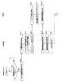
図5乃至図7は、給電制御の手順を示したフローチャートである。図中、細線の横矢印はアナログの制御信号の送受信を示し、太線の横矢印はCAN通信プロトコルに従った制御信号の送受信を示している。また、太線破線の横矢印はパイロット信号の送受信を示し、点線の横矢印はインバンド通信による制御信号の送受信を示している。
充電スタンド1の制御部12aは図示しない充電開始ボタンの操作状態を監視しており、充電開始ボタンがオン操作されたか否かを判定する(ステップS11)。充電開始ボタンが操作されていないと判定した場合(ステップS11:NO)、制御部12aは再びステップS11の処理を実行し、待機する。充電開始ボタンがオン操作されたと判定した場合(ステップS11:YES)、制御部12aは第1充電開始信号を中継機5へ出力する(ステップS12)。具体的には、制御部12aはアナログ制御通信部12bに制御命令を与え、リレーL1をオン状態に制御する。リレーL1がオン状態になると、フォトカプラP1がオン状態になる。5 to 7 are flowcharts showing the procedure of power supply control. In the figure, thin horizontal arrows indicate transmission / reception of analog control signals, and thick horizontal arrows indicate transmission / reception of control signals according to the CAN communication protocol. Further, a horizontal broken arrow indicates transmission / reception of a pilot signal, and a dotted horizontal arrow indicates transmission / reception of a control signal by in-band communication.
The control unit 12a of the charging
中継機5の制御部32aは充電開始操作を検知する(ステップS13)。具体的には、アナログ制御通信部32bはフォトカプラP1の電圧状態を監視しており、フォトカプラP1の受光素子によってフォトカプラP1がオン状態であることを検出する。フォトカプラP1がオン状態になった場合、アナログ制御通信部32bは、充電開始操作があったことを示す信号を制御部32aに与える。制御部32aは該信号を受信することで、充電開始操作を検知する。 The control part 32a of the
充電開始操作を検知した制御部32aはパイロット信号通信部32d及びインバンド通信部33を起動し(ステップS14)、中継機5と車両4が嵌合されている場合、パイロット信号通信部32dに制御命令を与え、9Vのパイロット信号を車輌4へ出力する(ステップS15)。なお、嵌合をしていない場合は、パイロット信号の電圧は12Vで一定である(図示せず)。また、インバンド通信部33の起動は、充電開始操作検知時と図5で記載しているが、9Vのパイロット信号出力時でも問題は無い。 The control unit 32a that has detected the charging start operation activates the pilot
車輌4側の制御部42aは、CPLT検出部42fによって、9Vのパイロット信号を検出することでコネクタ装置3の嵌合を検知する(ステップS16)。コネクタ装置3の嵌合が検知された場合、制御部42aは絶縁状態の確認を行い、コネクタをロックする(ステップS17)。次いで、制御部42aは絶縁状態の確認結果をCPLT制御部42eにて中継機5へ出力する(ステップS18)。 The
中継機5の制御部32aは、車輌4側から送信された絶縁状態の確認結果をCPLT検出部32fにて検出することによって取得し(ステップS19)、絶縁状態の確認結果を図示しない記憶部に記憶する(ステップS20)。そして、制御部32aはコネクタ装置3をロックする(ステップS21)。 The control unit 32a of the
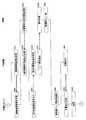
次いで、絶縁状態の確認結果を出力した車輌4側の制御部42aはインバンド通信部43によるインバンド通信を開始させ、通信が開始されることを示す制御信号を中継機5へ送信する(ステップS31)。中継機5の制御部32aはゲートウェイ処理を行い(ステップS32)、通信が開始されることを示す制御信号を充電スタンド1へ送信する。具体的には、制御部32aは、CAN通信部32cに制御命令を与え、通信が開始されることを示す制御信号をCAN通信プロトコルに従って充電スタンド1へ送信させる。充電スタンド1の制御部12aは中継機5から通信開始を示す制御信号を受信すると、CAN通信部12cによるCAN通信を開始させる(ステップS33)。 Next, the
車輌4及び充電スタンド1間で通信が成立すると、車輌4の制御部42aはインバンド通信部43に制御命令を与え、バッテリ情報をインバンド通信にて中継機5に送信させる(ステップS34)。中継機5の制御部32aは、ゲートウェイ処理によってバッテリ情報を充電スタンド1へ中継する(ステップS35)。つまり、制御部32aは、インバンド通信部33にてバッテリ情報を受信し、CAN通信部32cに制御命令を与えることによって、バッテリ情報をCAN通信プロトコルにて充電スタンド1へ送信する。バッテリ情報には、例えば最大電圧、電池容量、最大充電時間等の情報が含まれる。 When communication is established between the
充電スタンド1の制御部12aは中継機5から送信されたバッテリ情報をCAN通信部12cにて受信し(ステップS36)、バッテリ41に充電スタンド1が適合しているか否かを判定する(ステップS37)。充電対象のバッテリ41が充電スタンド1に適合していると判定した場合、制御部12aはCAN通信部12cに制御命令を与えることによって、充電スタンド1に関する充電スタンド情報をCAN通信プロトコルに従って中継機5へ送信させる(ステップS38)。充電スタンド情報には、例えば最大電圧、最大電流等の情報が含まれる。 The control unit 12a of the charging
中継機5の制御部32aは、ゲートウェイ処理によって充電スタンド情報を車輌4へ中継する(ステップS39)。つまり、制御部32aは、CAN通信部32cにて充電スタンド情報を受信し、インバンド通信部33に制御命令を与えることによって、充電スタンド情報をインバンド通信にて車輌4へ送信する。 The control unit 32a of the
車輌4側の制御部42aは、インバンド通信部43にて充電スタンド情報を受信し(ステップS40)、充電スタンド情報に基づいて、充電スタンド1にバッテリ41が適合しているか否かを判定する(ステップS41)。適合していると判定した場合、制御部42aはCPLT制御部42eに制御命令を与えることによって、車輌4側の充電準備が完了したことをパイロット信号によって中継機5へ通知する(ステップS42)。具体的には、制御部42aはCPLT制御部42eのスイッチSW2をオン状態にすることでパイロット信号の電圧を9Vから6Vに低下させる。中継機5の制御部32aは、CPLT検出部32fにて車輌4側で充電の準備が完了した旨の通知を検知する(ステップS43)。具体的には制御部32aはCPLT検出部32fにてパイロット信号の電圧が6Vに低下したことを検出することにより、充電の準備を検知する。 The
次いで、中継機5の制御部32aはアナログ制御通信部32bにて充電許可信号を充電スタンド1へ出力する(ステップS44)。具体的には、制御部32aはアナログ制御通信部32bに制御命令を与え、スイッチSW1をオン状態にする。スイッチSW1がオン状態になると、フォトカプラP4がオン状態になる。 Subsequently, the control part 32a of the
充電スタンド1側の制御部12aは充電許可信号を検知し(ステップS45)、充電許可信号を検知した制御部12aはコネクタ装置3をロックする(ステップS46)。具体的には、アナログ制御通信部12bはフォトカプラP4の電圧状態を監視しており、フォトカプラP4の受光素子によってフォトカプラP4がオン状態であることを検出した場合、フォトカプラP4がオン状態になったことを示す信号を制御部12aへ出力する。制御部12aは該信号を受信することで、充電許可信号を検知する。 The control unit 12a on the charging
ステップS43で充電許可信号を出力した中継機5の制御部32aは絶縁状態の確認結果をCAN通信部32cにて充電スタンド1へ送信する(ステップS51)。充電スタンド1の制御部12aはCAN通信部12cにて確認結果を受信する(ステップS52)。 The control unit 32a of the
一方、ステップS42で車輌4側の充電準備が完了したことを通知した制御部42aは充電に必要な充電電流を要求するための要求情報をインバンド通信部43にて中継機5へ送信する(ステップS53)。中継機5の制御部32aはインバンド通信部33にて充電の要求情報を受信し、記憶する(ステップS54)。 On the other hand, the
一方、ステップS52で絶縁確認結果を受信した充電スタンド1側の制御部12aは、アナログ制御通信部12bにて第2充電開始信号を出力する(ステップS55)。具体的にはアナログ制御通信部12bはリレーL2をオン状態に制御する。リレーL2がオン状態になると、フォトカプラP2がオン状態になる。 On the other hand, the controller 12a on the charging
中継機5の制御部32aは、第2充電開始信号を検知する(ステップS56)。具体的には、アナログ制御通信部32bはフォトカプラP2の電圧状態を監視しており、フォトカプラP2の受光素子によってフォトカプラP2がオン状態であることを検出し、フォトカプラP2がオン状態にあることを示す信号を制御部32aに与える。制御部32aは該信号を受信することによって、第2充電開始信号を検知する。 The control part 32a of the
第2充電開始信号を検知した制御部32aは、車輌4のリレーL4を閉鎖すべき旨を示した通知情報をインバンド通信部33にて車輌4へ送信する(ステップS57)。車輌4側の制御部42aはインバンド通信部43にて通知情報を受信し(ステップS58)、制御部42aは、車輌4側のリレーL4を閉じる(ステップS59)。 The control part 32a which detected the 2nd charge start signal transmits the notification information which showed that the relay L4 of the
ステップS55で第2充電開始信号を出力した充電スタンド1側の制御部12aは、リレーL4の閉鎖状態を確認する(ステップS60)。 The controller 12a on the charging
一方、ステップS57で車輌4のリレーL4を閉鎖すべき旨を通知した中継機5の制御部32aは、充電命令をCAN通信部32cにて充電スタンド1に送信する(ステップS61)。充電スタンド1の制御部12aは、CAN通信部12cにて充電命令を受信し(ステップS62)、インバータ11を動作させてバッテリ41への給電を行う(ステップS63)。 On the other hand, the control unit 32a of the
充電中において、車輌4の制御部42aはバッテリ41の状態を監視し、充電が完了したか否かを判定する(ステップS71)。充電を完了していないと判定した場合(ステップS71:NO)、充電制御を継続する。なお、図8のフローチャートはステップS71の処理を繰り返し実行する処理になっているが、実際にはバッテリ41の充電状態に応じた充電電流の要求を車輌4から充電スタンド1へ送信することによって、充電制御を継続している。 During charging, the
充電を完了したと判定した場合(ステップS71:YES)、制御部42aは、給電停止の要求をパイロット信号通信部42dにて中継機5へ送信する(ステップS72)。具体的には制御部42aはCPLT制御部42eのスイッチSW2をオフ状態にすることでパイロット信号の電圧レベルを9Vに変更する。 If it is determined that charging has been completed (step S71: YES), the
中継機5の制御部32aは、CPLT検出部32fにて給電停止要求信号を検知する(ステップS73)。次いで、制御部32aはCAN通信部32cにて給電停止信号を充電スタンド1に要求する(ステップS74)。充電スタンド1の制御部12aはCAN通信部12cにて給電停止信号を検知し(ステップS75)、インバータ11の動作を停止させて給電を停止させる(ステップS76)。 The control unit 32a of the
また、中継機5の制御部32aは、アナログ制御通信部32bにて充電停止信号を充電スタンド1へ出力する(ステップS77)。具体的には制御部32aはアナログ制御通信部32bに与え、スイッチSW1をオフ状態にする。スイッチSW1がオフ状態になると、フォトカプラP4もオフ状態になる。 Moreover, the control part 32a of the
充電スタンド1の制御部12aは充電停止信号を検知する(ステップS78)。具体的にはアナログ制御通信部12bはフォトカプラP4の電圧状態を監視しており、フォトカプラP4の受光素子によってフォトカプラP4がオフ状態であることを検出した場合、フォトカプラP4がオフ状態になったことを示す信号を制御部12aへ出力する。制御部12aは該信号を受信することで、充電停止信号を検知する。 The controller 12a of the charging
充電停止信号を検知した制御部12aは、充電を終了するために必要な処理を実行し(ステップS79)する。 The control part 12a which detected the charge stop signal performs a process required in order to complete | finish charge (step S79).
次いで、中継機5の制御部32aは、コネクタ装置3のロック状態を解除する(ステップS80)。そして、車輌4の制御部42aは、車輌4側のリレーL4を開く(ステップS81)。 Next, the control unit 32a of the
次いで、制御部12aはCAN通信部12cによるCAN通信を終了させる(ステップS82)。 Next, the control unit 12a ends the CAN communication by the CAN communication unit 12c (step S82).
次いで、中継機5の制御部32aはCAN通信部32c及びインバンド通信部33によるCAN通信及びインバンド通信を停止させ(ステップS83)、車輌4側の制御部42aはインバンド通信部43によるインバンド通信を終了させ(ステップS84)、処理を終える。 Next, the control unit 32a of the
このように構成された中継機5、コネクタ装置3及び給電システムによれば、DC充電規格が異なる車輌4と、充電スタンド1との間で充電に係る制御信号を中継することにより、規格が異なる充電スタンド1によるバッテリ充電を低コストで実現することができる。 According to the
また、ユーザの車輌4が充電スタンド1のDC充電規格に対応していないと、バッテリ41を充電できず、規格に適合した充電スタンド1を探す間に電欠を起こす可能性があるが、本実施の形態によれば斯かる問題を解決することができる。 In addition, if the user's
更に、AC給電端子40aを絶縁部31によって確実に絶縁しているため、AC給電端子40aからバッテリ電流が外部へ供給される不測の事態を防止することが可能である。 Furthermore, since the AC power supply terminal 40a is reliably insulated by the insulating
更にまた、蓄電池である電源34を備えることにより、中継機5における電力供給の安全性を向上させることができる。なお、蓄電池は外部電源からも充電可能である。また、蓄電池以外でも、商用電力などから供給されるAC電力による起動や、太陽電池で電源を供給など、複数の方法がある。 Furthermore, by providing the
(変形例)
図9は変形例に係る給電システムの一構成例を示したブロック図である。変形例に係る給電システムは実施の形態1と同様の充電スタンド1、充電ケーブル2、コネクタ装置103及び車輌4を備える。変形例に係るコネクタ装置103は更に給電線21をオンオフする遮断スイッチ35を中継機105に備える。遮断スイッチ35のオンオフは、充電制御部32によって制御される。例えば、充電制御部32は、充電の許可があるまで遮断スイッチ35をオフ状態にしておき、充電スタンド1及び車輌4との通信によって充電の許可が確認できた場合、遮断スイッチ35をオン状態にするように遮断スイッチ35のオンオフを制御する。また、充電制御部32は、充電スタンド1又は車輌4から異常検知信号を受信した場合、又は図示しないセンサで過電流、過電圧、短絡等を検出した場合、遮断スイッチ35をオン状態に制御するようにしても良い。
このように遮断スイッチ35を備えることによって、給電システムの安全性を向上させることができる。
給電システムのその他の構成、作用及び効果は実施の形態1で説明した給電システムと同様であるため、対応する箇所には同様の符号を付してその詳細な説明を省略する。(Modification)
FIG. 9 is a block diagram illustrating a configuration example of a power feeding system according to a modification. The power supply system according to the modification includes a charging
By providing the cut-
Since other configurations, operations, and effects of the power feeding system are the same as those of the power feeding system described in the first embodiment, the corresponding portions are denoted by the same reference numerals and detailed description thereof is omitted.
(実施の形態2)
図10は実施の形態2に係る給電システムの一構成例を示したブロック図である。実施の形態2に係る給電システムは実施の形態1と同様の充電スタンド1、充電ケーブル202、コネクタ装置203及び車輌4を備える。ただし、中継機205がコネクタ装置203では無く、充電ケーブル2の途中に設けられている点が実施の形態1と異なる。
給電システムのその他の構成、作用及び効果は実施の形態1で説明した給電システムと同様であるため、対応する箇所には同様の符号を付してその詳細な説明を省略する。
なお、実施の形態1及び2では中継機5をコネクタ装置103及び充電ケーブル202に設ける例を説明したが、給電経路の他の箇所に中継機を設けても良い。例えば、充電スタンドに設けても良いし、車輌のインレットに設けても良い。また、コネクタ装置又はインレットに着脱可能なアダプタとして構成しても良い。(Embodiment 2)
FIG. 10 is a block diagram illustrating a configuration example of the power feeding system according to the second embodiment. The power feeding system according to the second embodiment includes a charging
Since other configurations, operations, and effects of the power feeding system are the same as those of the power feeding system described in the first embodiment, the corresponding portions are denoted by the same reference numerals and detailed description thereof is omitted.
In the first and second embodiments, the example in which the
今回開示された実施の形態はすべての点で例示であって、制限的なものではないと考えられるべきである。本発明の範囲は、上記した意味ではなく、特許請求の範囲によって示され、特許請求の範囲と均等の意味及び範囲内でのすべての変更が含まれることが意図される。
また、インバンド通信に認証、課金などのデータを付与する場合、中継機で処理することが可能である。その為に、中継機を内蔵したコネクタ装置にカードリーダなどの個人情報を特定する機能や電子マネー決済機能などを設けても良い。
また、充電スタンド内のインバータ(11)や充電制御部(12)、コネクタ装置内の充電制御部(32)、車輌内の充電制御部(42)内に複数の機能を一体化させているが、別のユニットとしても良い。The embodiment disclosed this time is to be considered as illustrative in all points and not restrictive. The scope of the present invention is defined by the terms of the claims, rather than the meanings described above, and is intended to include any modifications within the scope and meaning equivalent to the terms of the claims.
In addition, when data such as authentication and billing is added to in-band communication, it can be processed by a repeater. For this purpose, a connector device incorporating a repeater may be provided with a function for identifying personal information such as a card reader, an electronic money settlement function, and the like.
In addition, a plurality of functions are integrated in the inverter (11) and the charging controller (12) in the charging stand, the charging controller (32) in the connector device, and the charging controller (42) in the vehicle. It may be a separate unit.
1 充電スタンド
2 充電ケーブル
3 コネクタ装置
4 車輌
5 中継機
6 交流電源
11 インバータ
11a AC/DC変換部
11b 保護回路
12 充電制御部
12a 制御部
12b アナログ制御通信部
12c CAN通信部
12d 地絡検知部
21 給電線
22 アナログ制御線
22a 第1の通信線
22b 第2の通信線
22c 第3の通信線
22d 第4の通信線
22e 第5の通信線
23 CAN通信線
31 絶縁部
32 充電制御部
32a 制御部
32b アナログ制御通信部
32c CAN通信部
32d パイロット信号通信部(パルス信号通信部)
32e CPLT出力部
32f CPLT検出部
32g 発振器
33 インバンド通信部
34 電源
35 遮断スイッチ
40 インレット
40a AC給電端子(車輌側端子)
41 バッテリ
41a 充電器
42 充電制御部
42a 制御部
42d パイロット信号通信部(パルス信号通信部)
42e CPLT制御部
42f CPLT検出部
43 インバンド通信部DESCRIPTION OF
32e
41
42e
Claims (8)
Translated fromJapanese前記充電スタンドとの間でアナログの制御信号を送受信するアナログ制御通信部と、
前記充電スタンドとの間でCAN通信プロトコルに従って制御信号を送受信するCAN通信部と、
前記車輌との間でパルス波の制御信号を送受信するパルス信号通信部と、
前記パルス波の制御信号に重畳した他の制御信号を送受信するインバンド通信部と、
前記アナログ制御通信部及び前記CAN通信部にて受信した制御信号に応じた信号を前記パルス信号通信部及び前記インバンド通信部に送信させ、前記パルス信号通信部及び前記インバンド通信部にて受信した制御信号に応じた信号を前記アナログ制御通信部及び前記CAN通信部に送信させる制御部と
を備えることを特徴とする中継機。In a relay that relays a control signal related to charging between a vehicle equipped with a battery and a charging station that charges the battery by supplying direct current through a charging cable,
An analog control communication unit for transmitting and receiving an analog control signal to and from the charging station;
A CAN communication unit that transmits and receives control signals to and from the charging station according to a CAN communication protocol;
A pulse signal communication unit for transmitting and receiving a pulse wave control signal to and from the vehicle;
An in-band communication unit that transmits and receives another control signal superimposed on the control signal of the pulse wave;
A signal corresponding to the control signal received by the analog control communication unit and the CAN communication unit is transmitted to the pulse signal communication unit and the in-band communication unit, and received by the pulse signal communication unit and the in-band communication unit. A relay unit comprising: a control unit that causes the analog control communication unit and the CAN communication unit to transmit a signal corresponding to the control signal.
ことを特徴とする請求項1に記載の中継機。The repeater according to claim 1, further comprising a power source that supplies power to each communication unit.
ことを特徴とする請求項1又は請求項2に記載の中継機。The relay unit according to claim 1, further comprising an insulating unit that insulates a vehicle-side terminal to which alternating current for charging the battery is input.
ことを特徴とする請求項1乃至請求項3のいずれか一つに記載の中継機。The relay device according to any one of claims 1 to 3, further comprising a cut-off switch that cuts off power supply from the charging stand to the battery.
請求項1乃至請求項4のいずれか一つに記載の中継機を備える
ことを特徴とするコネクタ装置。In a connector device that connects a vehicle equipped with a battery and a charging cable,
The connector apparatus provided with the relay machine as described in any one of Claim 1 thru | or 4.
請求項1乃至請求項4のいずれか一つに記載の中継機を備える
ことを特徴とする充電ケーブル。In the charging cable that supplies direct current to the battery installed in the vehicle,
A charging cable comprising the repeater according to any one of claims 1 to 4.
該中継機との間でアナログの制御信号を送受信するアナログ制御通信部、及び前記中継機との間でCAN通信プロトコルに従って制御信号を送受信するCAN通信部を有する充電スタンドと
を備えることを特徴とする給電システム。A repeater according to any one of claims 1 to 4;
An analog control communication unit that transmits / receives an analog control signal to / from the repeater, and a charging station that has a CAN communication unit that transmits / receives a control signal to / from the repeater according to a CAN communication protocol. Power supply system.
該中継機との間でアナログの制御信号を送受信するアナログ制御通信部及び前記中継機との間でCAN通信プロトコルに従って制御信号を送受信するCAN通信部を有する充電スタンドと、
前記中継機との間でパルス波の制御信号を送受信するパルス信号通信部及び該パルス波の制御信号に重畳した他の制御信号を送受信するインバンド通信部を有する車輌と
を備えることを特徴とする給電システム。A repeater according to any one of claims 1 to 4;
A charging station having an analog control communication unit that transmits and receives analog control signals to and from the repeater and a CAN communication unit that transmits and receives control signals to and from the repeater according to a CAN communication protocol;
A vehicle having a pulse signal communication unit that transmits and receives a pulse wave control signal to and from the repeater, and an in-band communication unit that transmits and receives another control signal superimposed on the pulse wave control signal. Power supply system.
Priority Applications (2)
| Application Number | Priority Date | Filing Date | Title |
|---|---|---|---|
| JP2012278625AJP5942837B2 (en) | 2012-12-20 | 2012-12-20 | Relay machine, connector device, charging cable and power supply system |
| PCT/JP2013/075399WO2014097696A1 (en) | 2012-12-20 | 2013-09-20 | Relay device, connector device, charging cable, and power supply system |
Applications Claiming Priority (1)
| Application Number | Priority Date | Filing Date | Title |
|---|---|---|---|
| JP2012278625AJP5942837B2 (en) | 2012-12-20 | 2012-12-20 | Relay machine, connector device, charging cable and power supply system |
Publications (2)
| Publication Number | Publication Date |
|---|---|
| JP2014124033Atrue JP2014124033A (en) | 2014-07-03 |
| JP5942837B2 JP5942837B2 (en) | 2016-06-29 |
Family
ID=50978046
Family Applications (1)
| Application Number | Title | Priority Date | Filing Date |
|---|---|---|---|
| JP2012278625AExpired - Fee RelatedJP5942837B2 (en) | 2012-12-20 | 2012-12-20 | Relay machine, connector device, charging cable and power supply system |
Country Status (2)
| Country | Link |
|---|---|
| JP (1) | JP5942837B2 (en) |
| WO (1) | WO2014097696A1 (en) |
Cited By (15)
| Publication number | Priority date | Publication date | Assignee | Title |
|---|---|---|---|---|
| JP2015142412A (en)* | 2014-01-28 | 2015-08-03 | 株式会社デンソー | Charger and on-vehicle apparatus |
| JP5855212B1 (en)* | 2014-11-26 | 2016-02-09 | 三菱電機株式会社 | Charging system |
| JP2016096648A (en)* | 2014-11-14 | 2016-05-26 | 株式会社デンソー | Repeater |
| WO2017141329A1 (en)* | 2016-02-15 | 2017-08-24 | 三菱電機株式会社 | Protocol conversion apparatus |
| JP2017229230A (en)* | 2016-06-24 | 2017-12-28 | フォルクスヴァーゲン アクチエンゲゼルシャフトVolkswagen Aktiengesellschaft | Charging an electric vehicle using a signal conversion adapter |
| CN109130909A (en)* | 2018-07-27 | 2019-01-04 | 广州万城万充新能源科技有限公司 | A kind of intelligent connection apparatus of novel electric vehicle conduction charging |
| US10479209B2 (en) | 2015-08-05 | 2019-11-19 | Autonetwork Technologies, Ltd. | Relay device including a restriction unit |
| JP2020068618A (en)* | 2018-10-26 | 2020-04-30 | トヨタ自動車株式会社 | Power conversion unit |
| JP2020127296A (en)* | 2019-02-05 | 2020-08-20 | トヨタ自動車株式会社 | Controller of vehicle, vehicle with the same and control method of vehicle |
| JP2021506029A (en)* | 2017-12-29 | 2021-02-18 | ユラ コーポレーション カンパニー リミテッド | Software update device and software update method using it |
| JP2021040402A (en)* | 2019-09-02 | 2021-03-11 | パナソニックIpマネジメント株式会社 | Power conversion system, and cable support device |
| JP2021191059A (en)* | 2020-05-27 | 2021-12-13 | ニチコン株式会社 | Relay used in charging electric motor car |
| JP2022525901A (en)* | 2019-03-19 | 2022-05-20 | ディーシーベル インコーポレイテッド | EV charger with adaptive charging protocol |
| JP2023086609A (en)* | 2021-12-10 | 2023-06-22 | 能海電能科技股▲分▼有限公司 | Charging system and power conversion box |
| JP7517755B1 (en) | 2023-11-22 | 2024-07-17 | 株式会社Yanekara | Connection device and information processing method |
Families Citing this family (2)
| Publication number | Priority date | Publication date | Assignee | Title |
|---|---|---|---|---|
| DK3142220T3 (en)* | 2014-11-11 | 2019-09-02 | Guangdong Oppo Mobile Telecommunications Corp Ltd | POWER ADAPTER AND TERMINAL |
| CN111180960B (en)* | 2020-02-18 | 2022-03-11 | 远景能源有限公司 | Charging adaptor for electric vehicle and charging protection method |
Citations (5)
| Publication number | Priority date | Publication date | Assignee | Title |
|---|---|---|---|---|
| JP2003047163A (en)* | 2001-08-01 | 2003-02-14 | Honda Motor Co Ltd | Charging method converting device |
| WO2010097922A1 (en)* | 2009-02-26 | 2010-09-02 | トヨタ自動車株式会社 | Plug conversion adapter |
| JP2011024341A (en)* | 2009-07-15 | 2011-02-03 | Nitto Electric Works Ltd | charging cable |
| WO2011077780A1 (en)* | 2009-12-24 | 2011-06-30 | 株式会社 日立製作所 | Power grid control system using electric vehicle, power grid control apparatus, information distribution apparatus, and information distribution method |
| JP2012210080A (en)* | 2011-03-30 | 2012-10-25 | Mitsubishi Electric Corp | Charging/discharging system |
Family Cites Families (4)
| Publication number | Priority date | Publication date | Assignee | Title |
|---|---|---|---|---|
| US5369352A (en)* | 1993-04-26 | 1994-11-29 | Ford Motor Company | Universal electric vehicle charging adapter |
| JP2012034554A (en)* | 2009-08-21 | 2012-02-16 | Jfe Engineering Corp | Fast charger |
| US20130169226A1 (en)* | 2011-12-30 | 2013-07-04 | Electric Transportation Engineering Corporation d/b/a ECOtality North America | Electricity transfer system for modifying an electric vehicle charging station and method of providing, using, and supporting the same |
| US9071074B2 (en)* | 2012-02-20 | 2015-06-30 | Eaton Corporation | Multi-standard, alternating current or direct current compatible electric vehicle supply equipment |
- 2012
- 2012-12-20JPJP2012278625Apatent/JP5942837B2/ennot_activeExpired - Fee Related
- 2013
- 2013-09-20WOPCT/JP2013/075399patent/WO2014097696A1/enactiveApplication Filing
Patent Citations (5)
| Publication number | Priority date | Publication date | Assignee | Title |
|---|---|---|---|---|
| JP2003047163A (en)* | 2001-08-01 | 2003-02-14 | Honda Motor Co Ltd | Charging method converting device |
| WO2010097922A1 (en)* | 2009-02-26 | 2010-09-02 | トヨタ自動車株式会社 | Plug conversion adapter |
| JP2011024341A (en)* | 2009-07-15 | 2011-02-03 | Nitto Electric Works Ltd | charging cable |
| WO2011077780A1 (en)* | 2009-12-24 | 2011-06-30 | 株式会社 日立製作所 | Power grid control system using electric vehicle, power grid control apparatus, information distribution apparatus, and information distribution method |
| JP2012210080A (en)* | 2011-03-30 | 2012-10-25 | Mitsubishi Electric Corp | Charging/discharging system |
Cited By (27)
| Publication number | Priority date | Publication date | Assignee | Title |
|---|---|---|---|---|
| JP2015142412A (en)* | 2014-01-28 | 2015-08-03 | 株式会社デンソー | Charger and on-vehicle apparatus |
| JP2016096648A (en)* | 2014-11-14 | 2016-05-26 | 株式会社デンソー | Repeater |
| JP5855212B1 (en)* | 2014-11-26 | 2016-02-09 | 三菱電機株式会社 | Charging system |
| US10479209B2 (en) | 2015-08-05 | 2019-11-19 | Autonetwork Technologies, Ltd. | Relay device including a restriction unit |
| US10668820B2 (en) | 2016-02-15 | 2020-06-02 | Mitsubishi Electric Corporation | Protocol conversion apparatus for electric vehicle |
| WO2017141329A1 (en)* | 2016-02-15 | 2017-08-24 | 三菱電機株式会社 | Protocol conversion apparatus |
| JPWO2017141329A1 (en)* | 2016-02-15 | 2018-05-31 | 三菱電機株式会社 | Protocol converter |
| JP2017229230A (en)* | 2016-06-24 | 2017-12-28 | フォルクスヴァーゲン アクチエンゲゼルシャフトVolkswagen Aktiengesellschaft | Charging an electric vehicle using a signal conversion adapter |
| US10421365B2 (en) | 2016-06-24 | 2019-09-24 | Volkswagen Ag | Electric charging of electric vehicles by adapter for signal conversion |
| JP2021506029A (en)* | 2017-12-29 | 2021-02-18 | ユラ コーポレーション カンパニー リミテッド | Software update device and software update method using it |
| CN109130909A (en)* | 2018-07-27 | 2019-01-04 | 广州万城万充新能源科技有限公司 | A kind of intelligent connection apparatus of novel electric vehicle conduction charging |
| CN109130909B (en)* | 2018-07-27 | 2023-11-10 | 广州万城万充新能源科技有限公司 | Intelligent connection device for conducting and charging electric automobile |
| JP2020068618A (en)* | 2018-10-26 | 2020-04-30 | トヨタ自動車株式会社 | Power conversion unit |
| JP7371732B2 (en) | 2019-02-05 | 2023-10-31 | トヨタ自動車株式会社 | Vehicle control device, vehicle equipped with the same, and vehicle control method |
| JP7115344B2 (en) | 2019-02-05 | 2022-08-09 | トヨタ自動車株式会社 | VEHICLE CONTROL DEVICE, VEHICLE INCLUDING THE SAME, AND VEHICLE CONTROL METHOD |
| JP2022137222A (en)* | 2019-02-05 | 2022-09-21 | トヨタ自動車株式会社 | VEHICLE CONTROL DEVICE, VEHICLE INCLUDING THE SAME, AND VEHICLE CONTROL METHOD |
| JP2020127296A (en)* | 2019-02-05 | 2020-08-20 | トヨタ自動車株式会社 | Controller of vehicle, vehicle with the same and control method of vehicle |
| JP2022525901A (en)* | 2019-03-19 | 2022-05-20 | ディーシーベル インコーポレイテッド | EV charger with adaptive charging protocol |
| JP7684222B2 (en) | 2019-03-19 | 2025-05-27 | ディーシーベル インコーポレイテッド | EV charger with adaptive charging protocol |
| US12377748B2 (en) | 2019-03-19 | 2025-08-05 | dcbel Inc. | Smart EV charger with adaptive interface and multi-protocol compatibility |
| JP7217431B2 (en) | 2019-09-02 | 2023-02-03 | パナソニックIpマネジメント株式会社 | Power conversion system and cable support |
| JP2021040402A (en)* | 2019-09-02 | 2021-03-11 | パナソニックIpマネジメント株式会社 | Power conversion system, and cable support device |
| JP2021191059A (en)* | 2020-05-27 | 2021-12-13 | ニチコン株式会社 | Relay used in charging electric motor car |
| JP7407658B2 (en) | 2020-05-27 | 2024-01-04 | ニチコン株式会社 | Repeater used when charging electric vehicles |
| JP2023086609A (en)* | 2021-12-10 | 2023-06-22 | 能海電能科技股▲分▼有限公司 | Charging system and power conversion box |
| JP2025084543A (en)* | 2023-11-22 | 2025-06-03 | 株式会社Yanekara | Connection device and information processing method |
| JP7517755B1 (en) | 2023-11-22 | 2024-07-17 | 株式会社Yanekara | Connection device and information processing method |
Also Published As
| Publication number | Publication date |
|---|---|
| JP5942837B2 (en) | 2016-06-29 |
| WO2014097696A1 (en) | 2014-06-26 |
Similar Documents
| Publication | Publication Date | Title |
|---|---|---|
| JP5942837B2 (en) | Relay machine, connector device, charging cable and power supply system | |
| JP5942838B2 (en) | Relay machine, connector device, charging cable and power supply system | |
| JP5234159B2 (en) | A vehicle including a power storage unit capable of discharging (power feeding) to an external load, a discharge system including the vehicle and a power cable, a discharge control method for the power storage unit, and a device outside the vehicle used in the discharge system. | |
| CN107867186B (en) | Electric vehicles and methods of charging between electric vehicles | |
| KR101877602B1 (en) | Security method and apparatus for electric vehicle power transfer system | |
| JP5365366B2 (en) | Vehicle charging system | |
| US9889758B2 (en) | Charging system, vehicle, and charging facility | |
| EP2733815B1 (en) | Charging apparatus | |
| CN104283238B (en) | Onboard wireless charging system for mobile terminal | |
| CN111231699B (en) | Car is device and vehicle of filling each other | |
| CN104283239B (en) | Onboard wireless charging system for mobile terminal | |
| CN108454440B (en) | A vehicle-to-vehicle charging device and method | |
| CN109562700B (en) | Arrangement comprising a motor vehicle and a connecting device, motor vehicle and connecting device | |
| US20120029728A1 (en) | Charging device for vehicle and vehicle | |
| KR20150105651A (en) | Vehicle | |
| CN102548790A (en) | Electrical connection device for hybrid and electric vehicles and associated method for charging | |
| EP3640081B1 (en) | Vehicle and charging system | |
| JP2013179723A (en) | Charge device and charge method | |
| US9108522B2 (en) | Vehicle-mounted controller | |
| JP4223202B2 (en) | Charge system converter | |
| JP6469307B2 (en) | Charge / discharge device | |
| CN109274159A (en) | A kind of charging system | |
| JP2010124556A (en) | Power feed device and vehicle | |
| US20230018075A1 (en) | Vehicle and charging system | |
| CN215244386U (en) | New energy automobile charging system |
Legal Events
| Date | Code | Title | Description |
|---|---|---|---|
| A621 | Written request for application examination | Free format text:JAPANESE INTERMEDIATE CODE: A621 Effective date:20150129 | |
| TRDD | Decision of grant or rejection written | ||
| A01 | Written decision to grant a patent or to grant a registration (utility model) | Free format text:JAPANESE INTERMEDIATE CODE: A01 Effective date:20160426 | |
| A61 | First payment of annual fees (during grant procedure) | Free format text:JAPANESE INTERMEDIATE CODE: A61 Effective date:20160509 | |
| R150 | Certificate of patent or registration of utility model | Ref document number:5942837 Country of ref document:JP Free format text:JAPANESE INTERMEDIATE CODE: R150 | |
| LAPS | Cancellation because of no payment of annual fees |